WO2014156092A1 - リチウムイオン電池 - Google Patents
リチウムイオン電池 Download PDFInfo
- Publication number
- WO2014156092A1 WO2014156092A1 PCT/JP2014/001622 JP2014001622W WO2014156092A1 WO 2014156092 A1 WO2014156092 A1 WO 2014156092A1 JP 2014001622 W JP2014001622 W JP 2014001622W WO 2014156092 A1 WO2014156092 A1 WO 2014156092A1
- Authority
- WO
- WIPO (PCT)
- Prior art keywords
- negative electrode
- positive electrode
- lithium
- metal film
- lithium metal
- Prior art date
- Legal status (The legal status is an assumption and is not a legal conclusion. Google has not performed a legal analysis and makes no representation as to the accuracy of the status listed.)
- Ceased
Links
Images
Classifications
-
- H—ELECTRICITY
- H01—ELECTRIC ELEMENTS
- H01M—PROCESSES OR MEANS, e.g. BATTERIES, FOR THE DIRECT CONVERSION OF CHEMICAL ENERGY INTO ELECTRICAL ENERGY
- H01M10/00—Secondary cells; Manufacture thereof
- H01M10/05—Accumulators with non-aqueous electrolyte
- H01M10/052—Li-accumulators
- H01M10/0525—Rocking-chair batteries, i.e. batteries with lithium insertion or intercalation in both electrodes; Lithium-ion batteries
-
- H—ELECTRICITY
- H01—ELECTRIC ELEMENTS
- H01M—PROCESSES OR MEANS, e.g. BATTERIES, FOR THE DIRECT CONVERSION OF CHEMICAL ENERGY INTO ELECTRICAL ENERGY
- H01M10/00—Secondary cells; Manufacture thereof
- H01M10/05—Accumulators with non-aqueous electrolyte
- H01M10/058—Construction or manufacture
- H01M10/0587—Construction or manufacture of accumulators having only wound construction elements, i.e. wound positive electrodes, wound negative electrodes and wound separators
-
- H—ELECTRICITY
- H01—ELECTRIC ELEMENTS
- H01M—PROCESSES OR MEANS, e.g. BATTERIES, FOR THE DIRECT CONVERSION OF CHEMICAL ENERGY INTO ELECTRICAL ENERGY
- H01M50/00—Constructional details or processes of manufacture of the non-active parts of electrochemical cells other than fuel cells, e.g. hybrid cells
- H01M50/40—Separators; Membranes; Diaphragms; Spacing elements inside cells
- H01M50/409—Separators, membranes or diaphragms characterised by the material
- H01M50/411—Organic material
- H01M50/414—Synthetic resins, e.g. thermoplastics or thermosetting resins
- H01M50/417—Polyolefins
-
- H—ELECTRICITY
- H01—ELECTRIC ELEMENTS
- H01M—PROCESSES OR MEANS, e.g. BATTERIES, FOR THE DIRECT CONVERSION OF CHEMICAL ENERGY INTO ELECTRICAL ENERGY
- H01M50/00—Constructional details or processes of manufacture of the non-active parts of electrochemical cells other than fuel cells, e.g. hybrid cells
- H01M50/40—Separators; Membranes; Diaphragms; Spacing elements inside cells
- H01M50/409—Separators, membranes or diaphragms characterised by the material
- H01M50/431—Inorganic material
-
- H—ELECTRICITY
- H01—ELECTRIC ELEMENTS
- H01M—PROCESSES OR MEANS, e.g. BATTERIES, FOR THE DIRECT CONVERSION OF CHEMICAL ENERGY INTO ELECTRICAL ENERGY
- H01M50/00—Constructional details or processes of manufacture of the non-active parts of electrochemical cells other than fuel cells, e.g. hybrid cells
- H01M50/40—Separators; Membranes; Diaphragms; Spacing elements inside cells
- H01M50/409—Separators, membranes or diaphragms characterised by the material
- H01M50/449—Separators, membranes or diaphragms characterised by the material having a layered structure
-
- Y—GENERAL TAGGING OF NEW TECHNOLOGICAL DEVELOPMENTS; GENERAL TAGGING OF CROSS-SECTIONAL TECHNOLOGIES SPANNING OVER SEVERAL SECTIONS OF THE IPC; TECHNICAL SUBJECTS COVERED BY FORMER USPC CROSS-REFERENCE ART COLLECTIONS [XRACs] AND DIGESTS
- Y02—TECHNOLOGIES OR APPLICATIONS FOR MITIGATION OR ADAPTATION AGAINST CLIMATE CHANGE
- Y02E—REDUCTION OF GREENHOUSE GAS [GHG] EMISSIONS, RELATED TO ENERGY GENERATION, TRANSMISSION OR DISTRIBUTION
- Y02E60/00—Enabling technologies; Technologies with a potential or indirect contribution to GHG emissions mitigation
- Y02E60/10—Energy storage using batteries
-
- Y—GENERAL TAGGING OF NEW TECHNOLOGICAL DEVELOPMENTS; GENERAL TAGGING OF CROSS-SECTIONAL TECHNOLOGIES SPANNING OVER SEVERAL SECTIONS OF THE IPC; TECHNICAL SUBJECTS COVERED BY FORMER USPC CROSS-REFERENCE ART COLLECTIONS [XRACs] AND DIGESTS
- Y02—TECHNOLOGIES OR APPLICATIONS FOR MITIGATION OR ADAPTATION AGAINST CLIMATE CHANGE
- Y02P—CLIMATE CHANGE MITIGATION TECHNOLOGIES IN THE PRODUCTION OR PROCESSING OF GOODS
- Y02P70/00—Climate change mitigation technologies in the production process for final industrial or consumer products
- Y02P70/50—Manufacturing or production processes characterised by the final manufactured product
-
- Y—GENERAL TAGGING OF NEW TECHNOLOGICAL DEVELOPMENTS; GENERAL TAGGING OF CROSS-SECTIONAL TECHNOLOGIES SPANNING OVER SEVERAL SECTIONS OF THE IPC; TECHNICAL SUBJECTS COVERED BY FORMER USPC CROSS-REFERENCE ART COLLECTIONS [XRACs] AND DIGESTS
- Y02—TECHNOLOGIES OR APPLICATIONS FOR MITIGATION OR ADAPTATION AGAINST CLIMATE CHANGE
- Y02T—CLIMATE CHANGE MITIGATION TECHNOLOGIES RELATED TO TRANSPORTATION
- Y02T10/00—Road transport of goods or passengers
- Y02T10/60—Other road transportation technologies with climate change mitigation effect
- Y02T10/70—Energy storage systems for electromobility, e.g. batteries
Definitions
- the present invention relates to a lithium ion battery, particularly a lithium ion battery separator.
- Metal materials that can be alloyed with lithium such as silicon, germanium, tin and zinc instead of carbonaceous materials such as graphite as negative electrode active materials, and these metals for higher energy density and higher output of lithium ion batteries
- silicon, germanium, tin and zinc instead of carbonaceous materials such as graphite as negative electrode active materials, and these metals for higher energy density and higher output of lithium ion batteries
- carbonaceous materials such as graphite
- the irreversible capacity of the negative electrode active material composed of a metal material alloyed with lithium or an oxide of these metals is larger than the irreversible capacity of the carbonaceous material, there is a problem that the battery capacity does not reach a desired value.
- Patent Document 1 discloses a lithium ion battery separator in which a lithium powder subjected to stabilization treatment is attached to a separator having an average particle size of 20 ⁇ m on a separator mainly composed of polyolefin. If the separator for lithium ion batteries disclosed in Patent Document 1 is used, lithium can be supplemented to the irreversible capacity of the negative electrode by the stabilized lithium powder, so that the battery capacity is improved.
- the positive and negative electrodes are short-circuited through the lithium powder, causing a leak test failure and a decrease in safety due to an internal short circuit.
- a positive electrode plate including a positive electrode current collector and a positive electrode active material layer formed on the surface of the positive electrode current collector, and a negative electrode active material formed on the surfaces of the negative electrode current collector and the negative electrode current collector.
- a negative electrode plate including a material layer; a separator that separates the positive electrode plate and the negative electrode plate; and a non-aqueous electrolyte solution that includes a non-aqueous solvent and an electrolyte salt.
- a homogeneous lithium metal film is formed on a portion not facing the negative electrode active material layer, and the lithium metal film is electrically insulated from the positive electrode current collector.
- the lithium metal film facing the negative electrode active material layer is taken into the negative electrode active material, and safety deterioration such as an internal short circuit caused by the remaining lithium metal layer is suppressed.
- a lithium ion battery having high charge / discharge efficiency, excellent cycle characteristics, and no leak test failure can be obtained.
- the lithium ion battery of the present invention will be described in detail using various experimental examples.
- the experimental examples shown below are illustrated to explain an example of a lithium ion battery for embodying the technical idea of the present invention, and the present invention is limited to any of these experimental examples. Not intended.
- the present invention can be equally applied to those in which various modifications are made to those shown in these experimental examples without departing from the technical idea shown in the claims.
- This negative electrode mixture slurry was applied to both surfaces of a negative electrode current collector sheet made of a copper foil having a thickness of 10 ⁇ m, dried, cut into a size corresponding to a battery case made of a predetermined laminate material after rolling, and Experimental Example 1
- the negative electrode used with a lithium ion battery was obtained.
- the charge capacity of this negative electrode was 5.0 mAh / cm 2 .
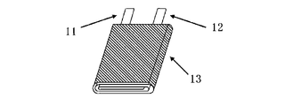
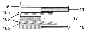
- an insulating tape 19 was attached to the positive electrode current collector at a contact portion with the separator end portion. Next, by pressing, a flat wound electrode group 13 was obtained as shown in FIG.
- an aluminum laminate film material was previously molded into a container so as to accommodate the flat wound electrode group 13 produced as described above. A thing was used.
- the flat wound electrode group 13 and the non-aqueous electrolyte prepared as described above are inserted into the outer package 14 in a carbon dioxide atmosphere at 25 ° C. and 1 atm, and the end of the aluminum laminate material is inserted.
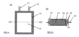
- the closed part 15 was formed by heat-sealing the parts, and a flat lithium ion battery 10 according to Experimental Example 1 having the structure shown in FIGS. 2A and 2B was produced.
- Example 3 The lithium ion battery of Experimental Example 3 is the same as that of Experimental Example 1, except that the positive electrode current collector was not attached with the insulating tape 19 and the lithium metal film was removed 5 mm from the outermost end face of the separator. The thing of the structure of this was produced.
- Comparative Example 1 As the lithium ion battery of Comparative Example 1, a battery having the same configuration as that of Experimental Example 1 was prepared except that the insulating tape 19 was not attached to the positive electrode current collector.
- Comparative Example 2 As a lithium ion battery of Comparative Example 2, a battery having the same configuration as that of Experimental Example 1 was prepared, except that a lithium metal film was not formed on the separator.
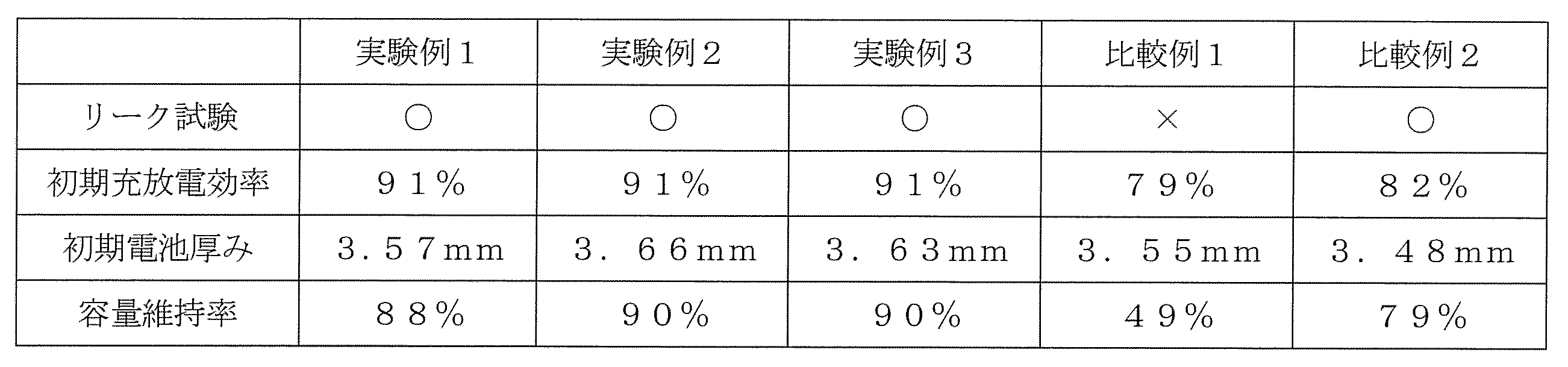
- the batteries of Experimental Examples 1 to 3 have a higher charge / discharge efficiency than the battery of Comparative Example 2 because an appropriate amount of Li is supplied from the lithium metal film to the negative electrode.
- the electrolytic solution is injected into the wound body of Comparative Example 1, the positive and negative electrodes are short-circuited through the lithium metal film, and further, the positive electrode is overdischarged due to the lithium metal being in contact with the positive electrode. descend.
- the lithium metal film in the battery of Comparative Example 1 remains in the same manner as in the batteries of Experimental Examples 1 to 3 after diffusing to both the positive and negative electrodes.
- the batteries of Experimental Examples 1 and 2 are increased compared to the battery of Experimental Example 3.
- the battery of Experimental Example 1 should increase in thickness by the thickness of the insulating tape (0.05 mm), and the battery of Experimental Example 2 should increase in thickness by one round of the separator (0.08 mm).
- the thickness of the lithium metal film was 4 ⁇ m, but the thickness of the lithium metal film is not particularly limited. However, the appropriate thickness of the lithium metal film varies depending on the irreversible capacity of the negative electrode active material layer to be used, and is preferably 2 ⁇ m or more and 26 ⁇ m or less. If the thickness of the lithium metal film is too small, the irreversible capacity in the negative electrode active material layer may not be sufficiently compensated, and the initial efficiency and cycle characteristics may not be sufficiently improved. If the thickness of the lithium metal film is too large, lithium is likely to precipitate on the negative electrode, which may reduce safety.
- the lithium metal film was removed by 5 mm from the end surface of the outermost periphery of the separator. Since the separator base material portion that has been wound around so as to cover the end portion of the lithium metal film, an internal short circuit caused by the lithium metal film can be suppressed.
- a negative electrode for a lithium ion battery according to one aspect of the present invention and a lithium ion battery using the negative electrode are, for example, a driving power source for a mobile information terminal such as a mobile phone, a notebook personal computer, and a PDA, and particularly required for high energy density Can be applied to.
- a mobile information terminal such as a mobile phone, a notebook personal computer, and a PDA
- high energy density Can be applied to.
- it can be expected to be used for high output applications such as electric vehicles (EV), hybrid electric vehicles (HEV, PHEV) and electric tools.
- EV electric vehicles
- HEV hybrid electric vehicles
- PHEV PHEV
Landscapes
- Chemical & Material Sciences (AREA)
- Chemical Kinetics & Catalysis (AREA)
- Electrochemistry (AREA)
- General Chemical & Material Sciences (AREA)
- Engineering & Computer Science (AREA)
- Manufacturing & Machinery (AREA)
- Materials Engineering (AREA)
- Inorganic Chemistry (AREA)
- Secondary Cells (AREA)
- Battery Electrode And Active Subsutance (AREA)
- Cell Separators (AREA)
Abstract
Description
実験例1のリチウムイオン電池は、次のようにして作製した。
リチウムコバルト複合酸化物(LiCoO2)100質量部と、アセチレンブラック1.5質量部と、ポリフッ化ビニリデン1.5質量部とを、適量のN-メチルピロリドン(NMP)とともにミキサーで混合し、正極合剤スラリーを調製した。
平均粒径(D50)6μmのSiO粒子10質量部と、平均粒径(D50)25μmの黒鉛粒子90質量部と、増粘剤としてのカルボキシメチルセルロース(CMC)1質量部と、結着剤としてのスチレンブタジエンラバー(SBR)1質量部とを、適量の水とともにミキサーで混合し、負極合剤スラリーを調製した。
厚さ20μmのポリプロピレン製の微多孔膜を基材として用い、厚さが4.0μmとなるように真空蒸着法(抵抗加熱にてリチウム源を蒸発)にて均質なリチウム金属膜を設け、実験例1のリチウムイオン電池で使用するセパレータを得た。
実験例1のリチウムイオン電池10の具体的製造工程を図1~図3を用いて説明する。上記のようにして作製された正極16の正極集電体の端部に正極タブ11を溶接し、同じく負極17の負極集電体の端部に負極タブ12を溶接した。次いで、正極16及び負極17を、2枚の上述のようにして作製されたセパレータ18を介して、正極16及び負極17が互いに絶縁された状態となるように、かつ、正極タブ11及び負極タブ12共に最外周側となるようにして、渦巻き状に巻回した。この際、リチウム金属膜が負極と対向するようにした。その後、巻回終端部に絶縁性の巻き止めテープを取り付けた。
実験例2のリチウムイオン電池としては、絶縁テープ19を貼付せず、リチウム金属膜が形成されたセパレータを一周余分に周回させる以外は、実験例1の場合と同様の構成とした。
実験例3のリチウムイオン電池としては、正極集電体に絶縁テープ19を貼付せず、リチウム金属膜をセパレータ最外周の端面から5mm除去したものを用いた以外は、実験例1の場合と同様の構成のものを作製した。
比較例1のリチウムイオン電池としては、正極集電体に絶縁テープ19を貼付しない以外は、実験例1の場合と同様の構成のものを作製した。
比較例2のリチウムイオン電池としては、セパレータにリチウム金属膜が形成されていない以外は、実験例1の場合と同様の構成のものを作製した。
上述のようにして作製された実験例1~3、比較例1および比較例2のそれぞれのリチウムイオン電池について、200kVの耐圧試験を行った。
また、以下のようにして初期充放電効率、容量維持率を測定した。なお、以下の全ての測定は、25℃の環境下で行った。
実験例1~3、比較例1および比較例2のそれぞれの組み立て直後のリチウムイオン電池について、0.5Itの定電流で電池電圧が4.3Vとなるまで充電し、電池電圧が4.3Vに達した後は、4.3Vの定電圧で充電電流が0.05Itとなるまで充電を行った。このときに流れた電気量を初回充電容量として求めた。次いで、0.2Itの定電流で電池電圧が3.0Vとなるまで放電させ、このときに流れた電気量を初回放電容量として求めた。そして、以下の計算式に基づいて初期充放電効率を求めた。
初期充放電効率(%)=(初回放電容量/初回充電容量)×100
また、初回充放電終了後に、初回充放電と同様の条件で充電をした電池の厚みを測定した。
実験例1~3、比較例1および比較例2のそれぞれの組み立て直後のリチウムイオン電池について、0.5Itの定電流で電池電圧が4.3Vとなるまで充電し、電池電圧が4.3Vに達した後は、4.3Vの定電圧で充電電流が0.05Itとなるまで充電を行った。次いで、1.0Itの定電流で電池電圧が3.0Vとなるまで放電させ、このときに流れた電気量を1サイクル目の放電容量として求めた。この充放電を1サイクルとして、200回繰り返し、200回目の放電時に流れた電気量を200サイクル目の放電容量として求めた。そして、以下の計算式に基づいて200サイクル目の容量維持率を求めた。結果を纏めて表1に示した。
容量維持率(%)
=(200サイクル目の放電容量/1サイクル目の放電容量)×100
11…正極タブ
12…負極タブ
13…巻回電極群
14…外装体
15…閉口部
16…正極
17…負極
18…セパレータ
18a…セパレータ基体
18b…リチウム金属層
19…絶縁テープ
Claims (4)
- 正極集電体および前記正極集電体の表面に形成された正極活物質層を含む正極板と、
負極集電体および前記負極集電体の表面に形成された負極活物質層を含む負極板と、
前記正極板及び前記負極板を隔離するセパレータと、
非水溶媒及び電解質塩を含む非水電解液とを備え、
前記セパレータは、ポリオレフィンを主材とし、前記負極板側の面上で、かつ前記負極活物質層との未対向部分に、均質なリチウム金属膜が形成され、
前記リチウム金属膜が前記正極集電体と電気的に絶縁されているリチウムイオン電池。 - 前記リチウム金属膜と前記正極集電体と間に非導電性物質が設けられている請求項1に記載のリチウムイオン電池。
- 前記セパレータの端面から所定の幅以上離れた位置に、前記リチウム金属膜の端部が存在し、前記所定の幅が前記リチウム金属膜の厚さである請求項1に記載のリチウムイオン電池。
- 前記リチウム金属膜の厚さが2μm以上、26μm以下である請求項1~3のいずれかに記載のリチウムイオン電池。
Priority Applications (3)
| Application Number | Priority Date | Filing Date | Title |
|---|---|---|---|
| JP2015508049A JPWO2014156092A1 (ja) | 2013-03-29 | 2014-03-20 | リチウムイオン電池 |
| US14/761,765 US20150357618A1 (en) | 2013-03-29 | 2014-03-20 | Lithium-ion cell |
| CN201480019215.6A CN105074998B (zh) | 2013-03-29 | 2014-03-20 | 锂离子电池 |
Applications Claiming Priority (2)
| Application Number | Priority Date | Filing Date | Title |
|---|---|---|---|
| JP2013071443 | 2013-03-29 | ||
| JP2013-071443 | 2013-03-29 |
Publications (1)
| Publication Number | Publication Date |
|---|---|
| WO2014156092A1 true WO2014156092A1 (ja) | 2014-10-02 |
Family
ID=51623106
Family Applications (1)
| Application Number | Title | Priority Date | Filing Date |
|---|---|---|---|
| PCT/JP2014/001622 Ceased WO2014156092A1 (ja) | 2013-03-29 | 2014-03-20 | リチウムイオン電池 |
Country Status (4)
| Country | Link |
|---|---|
| US (1) | US20150357618A1 (ja) |
| JP (1) | JPWO2014156092A1 (ja) |
| CN (1) | CN105074998B (ja) |
| WO (1) | WO2014156092A1 (ja) |
Cited By (1)
| Publication number | Priority date | Publication date | Assignee | Title |
|---|---|---|---|---|
| JP2022547979A (ja) * | 2019-09-12 | 2022-11-16 | ビーワイディー カンパニー リミテッド | 電池セパレータ、電池及び電池パック |
Families Citing this family (1)
| Publication number | Priority date | Publication date | Assignee | Title |
|---|---|---|---|---|
| PL3503257T3 (pl) * | 2017-03-10 | 2021-08-02 | Lg Chem, Ltd. | Litowa bateria akumulatorowa |
Citations (4)
| Publication number | Priority date | Publication date | Assignee | Title |
|---|---|---|---|---|
| JP2003524857A (ja) * | 1997-07-21 | 2003-08-19 | デュラセル インコーポレイテッド | リチウムイオン電気化学電池 |
| JP2004055537A (ja) * | 2002-05-30 | 2004-02-19 | Matsushita Electric Ind Co Ltd | リチウムイオン二次電池 |
| JP2008305648A (ja) * | 2007-06-06 | 2008-12-18 | Fdk Corp | 非水系蓄電デバイス |
| JP2011216600A (ja) * | 2010-03-31 | 2011-10-27 | Jm Energy Corp | 蓄電デバイス |
Family Cites Families (3)
| Publication number | Priority date | Publication date | Assignee | Title |
|---|---|---|---|---|
| JP2006147392A (ja) * | 2004-11-22 | 2006-06-08 | Matsushita Electric Ind Co Ltd | 電池 |
| CN102082288A (zh) * | 2009-11-30 | 2011-06-01 | 比亚迪股份有限公司 | 一种锂离子二次电池及其制造方法 |
| CN102709592B (zh) * | 2012-06-01 | 2014-08-27 | 中国东方电气集团有限公司 | 一种锂离子二次电池及其制备方法 |
-
2014
- 2014-03-20 US US14/761,765 patent/US20150357618A1/en not_active Abandoned
- 2014-03-20 CN CN201480019215.6A patent/CN105074998B/zh active Active
- 2014-03-20 WO PCT/JP2014/001622 patent/WO2014156092A1/ja not_active Ceased
- 2014-03-20 JP JP2015508049A patent/JPWO2014156092A1/ja active Pending
Patent Citations (4)
| Publication number | Priority date | Publication date | Assignee | Title |
|---|---|---|---|---|
| JP2003524857A (ja) * | 1997-07-21 | 2003-08-19 | デュラセル インコーポレイテッド | リチウムイオン電気化学電池 |
| JP2004055537A (ja) * | 2002-05-30 | 2004-02-19 | Matsushita Electric Ind Co Ltd | リチウムイオン二次電池 |
| JP2008305648A (ja) * | 2007-06-06 | 2008-12-18 | Fdk Corp | 非水系蓄電デバイス |
| JP2011216600A (ja) * | 2010-03-31 | 2011-10-27 | Jm Energy Corp | 蓄電デバイス |
Cited By (2)
| Publication number | Priority date | Publication date | Assignee | Title |
|---|---|---|---|---|
| JP2022547979A (ja) * | 2019-09-12 | 2022-11-16 | ビーワイディー カンパニー リミテッド | 電池セパレータ、電池及び電池パック |
| JP7426477B2 (ja) | 2019-09-12 | 2024-02-01 | ビーワイディー カンパニー リミテッド | 電池セパレータ、電池及びその製造方法、及び、電池パック及びその製造方法 |
Also Published As
| Publication number | Publication date |
|---|---|
| CN105074998B (zh) | 2017-09-19 |
| CN105074998A (zh) | 2015-11-18 |
| US20150357618A1 (en) | 2015-12-10 |
| JPWO2014156092A1 (ja) | 2017-02-16 |
Similar Documents
| Publication | Publication Date | Title |
|---|---|---|
| CN103988357B (zh) | 非水电解液二次电池的制造方法 | |
| JP5218873B2 (ja) | リチウム二次電池およびその製造方法 | |
| CN104471829B (zh) | 二次电池的充电控制方法及充电控制装置 | |
| CN103733418B (zh) | 非水电解质二次电池 | |
| CN107078280A (zh) | 非水电解质二次电池 | |
| JP2015179565A (ja) | 非水電解質電池用電極、非水電解質二次電池及び電池パック | |
| JP2014225326A (ja) | 非水電解質二次電池 | |
| CN104037394A (zh) | 活性物质、电极、二次电池、电池组和电动车辆 | |
| JP2011192395A (ja) | 非水電解質二次電池 | |
| CN106063019A (zh) | 非水电解质二次电池 | |
| WO2011070748A1 (ja) | 非水電解質二次電池及びその充電方法 | |
| CN103563158A (zh) | 非水电解质二次电池 | |
| CN111725555B (zh) | 锂离子二次电池 | |
| WO2014119274A1 (ja) | リチウムイオン電池及びリチウムイオン電池用セパレータ | |
| JP2013062089A (ja) | リチウムイオン二次電池 | |
| CN107925069A (zh) | 二次电池用负极活性材料和包含它的二次电池 | |
| JP2018006289A (ja) | 非水電解質二次電池 | |
| WO2022188163A1 (zh) | 电解液、二次电池、电池模块、电池包和装置 | |
| JP6668876B2 (ja) | リチウムイオン二次電池の製造方法 | |
| CN106450425A (zh) | 非水电解液二次电池 | |
| CN106252729A (zh) | 制造非水电解质二次电池的方法 | |
| JP7228113B2 (ja) | 非水電解液二次電池 | |
| KR101639313B1 (ko) | 리튬 이차전지용 양극 및 이를 포함하는 리튬 이차전지 | |
| JP2013045658A (ja) | リチウム二次電池の容量回復方法 | |
| JPWO2014156092A1 (ja) | リチウムイオン電池 |
Legal Events
| Date | Code | Title | Description |
|---|---|---|---|
| WWE | Wipo information: entry into national phase |
Ref document number: 201480019215.6 Country of ref document: CN |
|
| 121 | Ep: the epo has been informed by wipo that ep was designated in this application |
Ref document number: 14775681 Country of ref document: EP Kind code of ref document: A1 |
|
| ENP | Entry into the national phase |
Ref document number: 2015508049 Country of ref document: JP Kind code of ref document: A |
|
| WWE | Wipo information: entry into national phase |
Ref document number: 14761765 Country of ref document: US |
|
| NENP | Non-entry into the national phase |
Ref country code: DE |
|
| 122 | Ep: pct application non-entry in european phase |
Ref document number: 14775681 Country of ref document: EP Kind code of ref document: A1 |