WO2014156090A1 - Permanent-magnet-embedded electric motor and method for manufacturing same - Google Patents
Permanent-magnet-embedded electric motor and method for manufacturing same Download PDFInfo
- Publication number
- WO2014156090A1 WO2014156090A1 PCT/JP2014/001619 JP2014001619W WO2014156090A1 WO 2014156090 A1 WO2014156090 A1 WO 2014156090A1 JP 2014001619 W JP2014001619 W JP 2014001619W WO 2014156090 A1 WO2014156090 A1 WO 2014156090A1
- Authority
- WO
- WIPO (PCT)
- Prior art keywords
- magnet
- permanent magnet
- electric motor
- embedded
- rotor
- Prior art date
Links
Images

Classifications
-
- H—ELECTRICITY
- H02—GENERATION; CONVERSION OR DISTRIBUTION OF ELECTRIC POWER
- H02K—DYNAMO-ELECTRIC MACHINES
- H02K1/00—Details of the magnetic circuit
- H02K1/06—Details of the magnetic circuit characterised by the shape, form or construction
- H02K1/22—Rotating parts of the magnetic circuit
- H02K1/27—Rotor cores with permanent magnets
- H02K1/2706—Inner rotors
- H02K1/272—Inner rotors the magnetisation axis of the magnets being perpendicular to the rotor axis
- H02K1/274—Inner rotors the magnetisation axis of the magnets being perpendicular to the rotor axis the rotor consisting of two or more circumferentially positioned magnets
- H02K1/2753—Inner rotors the magnetisation axis of the magnets being perpendicular to the rotor axis the rotor consisting of two or more circumferentially positioned magnets the rotor consisting of magnets or groups of magnets arranged with alternating polarity
- H02K1/276—Magnets embedded in the magnetic core, e.g. interior permanent magnets [IPM]
-
- H—ELECTRICITY
- H02—GENERATION; CONVERSION OR DISTRIBUTION OF ELECTRIC POWER
- H02K—DYNAMO-ELECTRIC MACHINES
- H02K1/00—Details of the magnetic circuit
- H02K1/02—Details of the magnetic circuit characterised by the magnetic material
-
- H—ELECTRICITY
- H02—GENERATION; CONVERSION OR DISTRIBUTION OF ELECTRIC POWER
- H02K—DYNAMO-ELECTRIC MACHINES
- H02K1/00—Details of the magnetic circuit
- H02K1/06—Details of the magnetic circuit characterised by the shape, form or construction
- H02K1/12—Stationary parts of the magnetic circuit
- H02K1/14—Stator cores with salient poles
-
- H—ELECTRICITY
- H02—GENERATION; CONVERSION OR DISTRIBUTION OF ELECTRIC POWER
- H02K—DYNAMO-ELECTRIC MACHINES
- H02K1/00—Details of the magnetic circuit
- H02K1/06—Details of the magnetic circuit characterised by the shape, form or construction
- H02K1/12—Stationary parts of the magnetic circuit
- H02K1/16—Stator cores with slots for windings
-
- H—ELECTRICITY
- H02—GENERATION; CONVERSION OR DISTRIBUTION OF ELECTRIC POWER
- H02K—DYNAMO-ELECTRIC MACHINES
- H02K15/00—Methods or apparatus specially adapted for manufacturing, assembling, maintaining or repairing of dynamo-electric machines
- H02K15/02—Methods or apparatus specially adapted for manufacturing, assembling, maintaining or repairing of dynamo-electric machines of stator or rotor bodies
- H02K15/03—Methods or apparatus specially adapted for manufacturing, assembling, maintaining or repairing of dynamo-electric machines of stator or rotor bodies having permanent magnets
-
- H—ELECTRICITY
- H02—GENERATION; CONVERSION OR DISTRIBUTION OF ELECTRIC POWER
- H02K—DYNAMO-ELECTRIC MACHINES
- H02K3/00—Details of windings
- H02K3/04—Windings characterised by the conductor shape, form or construction, e.g. with bar conductors
- H02K3/12—Windings characterised by the conductor shape, form or construction, e.g. with bar conductors arranged in slots
-
- H—ELECTRICITY
- H02—GENERATION; CONVERSION OR DISTRIBUTION OF ELECTRIC POWER
- H02K—DYNAMO-ELECTRIC MACHINES
- H02K2213/00—Specific aspects, not otherwise provided for and not covered by codes H02K2201/00 - H02K2211/00
- H02K2213/03—Machines characterised by numerical values, ranges, mathematical expressions or similar information
Definitions
- the present invention relates to an embedded permanent magnet electric motor having an embedded permanent magnet rotor configured by embedding a plurality of permanent magnets at predetermined intervals in a rotor core, and a method for manufacturing the same.
- Patent Document 1 In such a technical field, techniques as described in Patent Document 1 and Patent Document 2 are known.
- Patent Document 1 has a substantially cylindrical rotor core in which a plurality of permanent magnet holes are formed in the circumferential direction, and a permanent magnet disposed in a V shape that is accommodated in the magnet hole.
- a rotor having a configuration in which an axial thickness of a bridge portion formed between a direction outer side end portion and an outer peripheral portion is thinner than other portions is disclosed.
- Patent Document 2 discloses a rotor-core steel plate having a magnet slot for incorporating a magnet inside an outer peripheral edge, and applies a compressive residual stress to a bridge portion between the magnet slot and the outer peripheral edge. It is disclosed that a part is provided.
- the leakage magnetic flux is reduced by making the thickness of the bridge portion smaller than others, but since the leakage magnetic path cannot be completely covered, the leakage magnetic flux can be sufficiently reduced. Not.
- the embedded permanent magnet electric motor of the present invention has the following configuration. That is, it has the stator by which the coil
- the rotor includes a rotor core formed by laminating steel plates having a plurality of magnet embedding holes, and permanent magnets housed and held in the magnet embedding holes, respectively.
- the steel plate has a bridge portion formed between the end portion of the magnet embedding hole and the outer periphery of the steel plate, and the thickness of the bridge portion is configured to be thinner than the thickness other than the bridge portion. Further, the adjacent bridge portions are connected by a thin-walled connecting portion having a thickness smaller than the plate thickness other than the bridge portion.
- the magnetic flux generated from the permanent magnet flows through the bridge portion to the adjacent permanent magnet, but even if only the bridge portion is thinned, the magnetic resistance of the entire magnetic path does not increase. For this reason, the leakage flux can be reduced by connecting the bridge portion with a thin plate thickness so that the magnetic resistance of the entire magnetic path is increased.
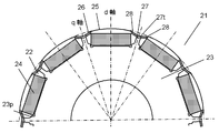
- FIG. 1 is a cross-sectional view of a permanent magnet embedded electric motor according to an embodiment of the present invention.
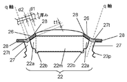
- FIG. 2A is an enlarged view of a main part of a rotor of the permanent magnet embedded type electric motor.
- FIG. 2B is an enlarged view of the periphery of the magnet embedding hole in the rotor.
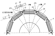
- FIG. 3 is an enlarged view of a main part of a rotor of an embedded permanent magnet electric motor according to another embodiment of the present invention.
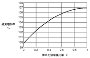
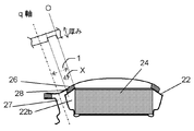
- FIG. 4A is a diagram showing the relationship between the ratio X of the thinned region and the magnetic flux increase rate.
- FIG. 4B is a diagram illustrating the ratio X of the thinned region.
- FIG. 5A is a diagram illustrating an example of a cross-sectional shape of the thin portion.
- FIG. 5B is a diagram showing another example of the cross-sectional shape of the thin portion.
- FIG. 1 is a cross-sectional view taken along a plane perpendicular to the central axis of rotation of an embedded permanent magnet electric motor 10 according to an embodiment of the present invention.
- the electric motor 10 includes a stator 11 and a rotor 21.
- Stator 11 includes a stator core 14 in which a plurality of thin steel plates are laminated, and a winding (not shown) wound around stator core 14.
- the stator core 14 has a yoke 12, a plurality of teeth 13 formed on the inner peripheral side of the yoke 12, and a plurality of slots 15 formed between adjacent teeth 13.
- the winding is wound around the stator core 14 by concentrated winding or distributed winding and is accommodated in the slot 15.
- the rotor 21 includes a rotor core 23 in which a plurality of magnet embedding holes 22 are formed at predetermined intervals in the circumferential direction, a permanent magnet 24 embedded in each magnet embedding hole 22, and the center of the rotor core 23. And a rotating shaft 29 arranged.
- the rotor core 23 is configured by laminating a plurality of thin steel plates, which are steel plates in which the magnet embedding holes 22 are formed, in the axial direction.
- the permanent magnet 24 for forming the magnetic pole of the rotor 21 is accommodated in each magnet embedding hole 22, and is hold
- the permanent magnet 24 is sandwiched and fixed by upper and lower end plates, or is fixed by a resin or an adhesive.
- the rotor core 23 is rotatably supported by a bearing (not shown) via a rotating shaft 29.
- the thus configured rotor 21 is opposed to the inner peripheral surface of the teeth 13 of the stator 11 via an air gap.
- the number of poles of the rotor 21 is 10 and the number of slots of the stator 11 is 12.
- the present invention is not limited to this combination, and other combinations are possible. It can also be applied.
- the permanent magnet 24 has shown the case of a flat plate shape, this is not limited to this shape, and is applicable also to arbitrary permanent magnet shapes, such as a U-shaped shape, a V-shaped shape, and a kamaboko shape. it can.
- the permanent magnet material can also be applied to any material such as a neodymium sintered magnet, a neodymium bonded magnet, a ferrite sintered magnet, and a ferrite bonded magnet.
- FIG. 2A is an enlarged cross-sectional view along a plane perpendicular to the rotation center axis of the rotor 21.
- FIG. 2B is the figure which expanded further the magnet embedding hole 22 of the rotor 21, and its periphery.
- FIG. 2B shows the magnet embedding hole 22 in a state where the permanent magnet 24 is not inserted.
- the magnet embedding hole 22 has a shape slightly larger than the cross-sectional area of the permanent magnet 24 to be inserted. That is, as shown in FIG. 2B, the magnet embedding hole 22 forms a hole having a cross-sectional shape including a magnet housing portion 22m, first gap portions 22a on both sides, and second gap portions 22b on both sides.
- the magnet storage portion 22m is a region in which the permanent magnet 24 is stored.
- the first gap portion 22 a is a gap that is formed at both ends in the circumferential direction of the magnet embedding hole 22 and becomes a portion where the permanent magnet 24 does not exist.
- the second gap portion 22b is a gap formed in the vicinity of both ends on the radially inner side of the magnet embedding hole 22.
- the permanent magnet 24 is positioned using the convex part 23p formed in the boundary of the 1st gap part 22a and the 2nd gap part 22b. Further, the permanent magnet 24 is mechanically fixed to the magnet embedding hole 22 with an end plate or the like, or is fixed and fixed with an adhesive or resin.
- a straight line connecting the rotation center of the rotor 21 and the magnetic pole center that is the center of one permanent magnet 24 is a d-axis, and the rotation center and the intermediate point where the permanent magnet 24 is adjacent to each other.
- the straight line connecting is defined as the q axis.
- the outer peripheral surface of the rotor 21 faces the vicinity of the center of each of the permanent magnets 24, and includes a first curved portion 25 having a radius R1 centered on the rotor center side, a first curved portion 25, and q It is formed by a second curved portion 26 connecting the axes.
- the radius R2 of the 2nd curve part 26 is comprised smaller than the radius R1 of a 1st curve part.
- the second curved portion may be configured by a straight line, or may be configured by only the first curved portion without the second curved portion (that is, the outer peripheral surface is configured by one circle).
- the thin iron plate of the rotor core 23 has a radial width between the end of the magnet embedding hole 22 and the outer periphery of the thin iron plate, that is, between the first gap portion 22a and the second curved portion 26.
- a bridge portion 28 of t1 is formed.
- the connection part 27 is formed as an iron plate part between adjacent magnet embedding holes 22.
- bridging part 28 is thinner than the plate
- the bridge portion 28 is thinned by crushing a thin steel plate with a press. The pressing may be performed on only one side of the thin steel plate or on both sides.
- the bridge portions 28 adjacent to each other across the q axis are connected by a thin connecting portion 27t that connects the adjacent bridge portions 28 to each other.
- the thin connection portion 27t is a part of the connection portion 27, and the plate thickness of the thin connection portion 27t is also thinner than the thickness d1 of other portions excluding the bridge portion 28.
- bridging part 28 and the thin connection part 27t is the same, it does not need to be especially the same.
- the magnetic flux generated from the permanent magnet 24 is configured to concentrate on the center of the magnetic pole, and the leakage magnetic flux flowing to the side between the magnetic poles (that is, in the q-axis direction) is suppressed as much as possible. Is preferred.
- Such a magnetic flux path also includes the connecting portion 27.
- the connecting portion 27 is thicker and has a larger area than the bridge portion 28, the magnetic resistance is smaller than that of the bridge portion 28. That is, even if the thickness of only the bridge portion 28 is made thin like the thickness d2 and the magnetic resistance at that portion is increased, the magnetic resistance of the magnetic path as a whole is affected by the connection portion 27 having a small magnetic resistance. Does not grow.
- the thin connection portion 27t which is a portion where the plate thickness is reduced, is provided so that the magnetic resistance also increases in the connection portion 27 included in the magnetic path. Adjacent bridge portions 28 are connected to each other through such thin-walled connecting portions 27t.
- FIG. 3 shows another embodiment of the thin connecting portion 27t of FIG. 2A, which has a large radial width t2, and is extended to the vicinity of the center of the side surface of the permanent magnet 24 at the connecting portion 27. It has become.
- the width h1 of the connecting portion 27 is larger than the width t1 of the bridge portion 28 when the magnetic flux flows to the adjacent permanent magnet 24 via the bridge portion 28. This also reduces the magnetic resistance. Therefore, in the configuration of FIG. 3, the radial width t ⁇ b> 2 of the thin connecting portion 27 t is larger than the radial width t ⁇ b> 1 of the bridge portion 28. That is, in the connection part 27, the area
- the magnetic resistance can be increased with respect to the magnetic flux leaking through the air gap by configuring the radial width t2 of the thin connecting portion 27t to be larger, and as a result, the magnetic flux leaking through the air gap can be reduced. Can do.
- the q-axis magnetic flux can be reduced by reducing the thickness of the thin steel plate on the q-axis. For this reason, it is possible to constitute a rotor having a small reluctance torque, that is, a small torque pulsation, despite being an embedded magnet type electric motor.
- FIG. 4A shows the relationship between the thickness reduction range formed by the bridge portion 28 and the thin connecting portion 27t and the amount of increase in generated magnetic flux.
- the horizontal axis is the thinned region width ratio, the width when thinned perpendicularly from the O line toward the q axis in FIG. 4B, and the width from the O line to the q axis is “1”, and the ratio X (0 to This is shown in 1).
- the magnetic flux increase rate improves by thinning not only a bridge
- the relationship between the plate thickness d2 of the bridge portion 28 and the radial width t1 of the bridge portion 28 is d2 ⁇ t1.
- the minimum punching width of a steel sheet is greater than or equal to the thickness of the steel sheet.
- twisting or deflection occurs, which affects the characteristics and accuracy of the motor.
- the width t1 of the bridge portion 28 is preferably small from the viewpoint of reducing the leakage magnetic flux, but is limited to the thickness of the steel sheet from the viewpoint of punching the steel sheet.
- a punching process of the magnet embedding hole 22 is provided, so that the punching minimum width portion is thinned before punching. That is, since the plate thickness d2 of the bridge portion 28 is first reduced, the width t1 can be reduced accordingly, and the above-described condition d2 ⁇ t1 becomes possible.
- the width t1 of the bridge portion 28 is t1 ⁇ d1, but it is reduced to the plate thickness d2 (d2 ⁇ d1) according to the present invention.
- the width t1 can be made smaller than the plate thickness d1 before crushing, and the leakage magnetic flux can be reduced to the minimum.
- the punching process of the magnet embedded holes 22 is provided after the pressing process.
- the width t1 of the bridge portion 28 can also be reduced to a minimum width that does not cause a problem in mechanical strength.
- variety t1 can be made into the minimum width
- the width t1 of the bridge portion 28 is determined by the minimum width that can be punched regardless of the mechanical strength, so that the present invention is useful.
- the rotor 21 is formed by punching a thin steel plate into a sheet shape and then laminating the sheets while rotating them at an arbitrary angle. If a step of thinning in the plate thickness direction is included, the elongation rate in the outer diameter direction varies depending on the direction of the plate material. For this reason, the shape changes in the rotation direction, and the cogging torque that causes vibration and noise is greatly deteriorated. In order to suppress such inconveniences, in the present embodiment, the thin steel plate is thinned in the thickness direction, and then the sheets are stacked while being rotated at an angle such that the magnet embedding holes 22 coincide. By forming the rotor 21 including such a procedure, variations in the outer diameter and magnetic characteristics due to directionality can be canceled out, and the cogging torque can be reduced.
- centrifugal force is generated when the rotor 21 rotates.
- This centrifugal force causes the permanent magnet 24 to stick to the outer peripheral side of the rotor, and stress is concentrated locally on the bridge portion holding the iron core on the outer peripheral side of the permanent magnet 24.
- the permanent magnet 24 is fixed by enclosing a resin or the like in the magnet embedding hole 22.
- the magnet embedding hole 22 into which the permanent magnet 24 is inserted with a resin or an adhesive
- the rotor core, the permanent magnet 24 and the resin are integrated to disperse stress generated by centrifugal force. it can. For this reason, local stress concentration is relieved, the strength reduction due to the thinning of the bridge portion 28 is compensated, and a high-strength rotor can be obtained.
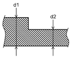
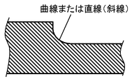
- FIG. 5A and 5B show cross-sectional views (indicated by arrows A in FIG. 3) of the thin steel plate of the rotor.
- FIG. 5A shows a case where no gradient is applied to the boundary surface changing from the plate thickness d1 of the thin steel plate before the crushing of the bridge portion 28 to the plate thickness d2 after being crushed. It shows the case where a curve or straight line with a slope is attached.
- the stress generated by the centrifugal force is concentrated at the boundary that changes from the plate thickness d1 before crushing to the plate thickness d2 after crushing, as shown in FIG. 5A.
- the boundary surface is composed of a curve or a straight line having an arbitrary gradient as shown in FIG. 5B
- the stress can be dispersed as a whole without concentrating on a specific location. That is, with the configuration as shown in FIG. 5B, the strength of the rotor can be improved, and for example, the rotor can be rotated at high speed without breaking.
- the plate thickness of the bridge portion and the thin connecting portion connecting the bridge portion is made thinner than the plate thickness of the steel plate. For this reason, according to the present invention, the leakage flux of the magnet can be reduced to the minimum, and the torque of the electric motor can be further increased.
- the application field of the present invention is not particularly limited, and can be widely used as, for example, an electric motor including a permanent magnet embedded rotor.
Abstract
Description
11 固定子
12 ヨーク
13 ティース
14 固定子鉄心
15 スロット
21 回転子
22 磁石埋設孔
23 回転子鉄心
24 永久磁石
25 第1曲線部
26 第2曲線部
27 連結部
27t 薄肉連結部
28 ブリッジ部
29 回転軸 DESCRIPTION OF
Claims (9)
- 固定子鉄心に巻線が巻回された固定子と、前記固定子鉄心の内周面とギャップを介して回転自在に配置された回転子とを備えた永久磁石埋込型電動機であって、
前記回転子は、複数の磁石埋設孔を有する鋼板を積層してなる回転子鉄心と、前記磁石埋設孔にそれぞれ収納保持された永久磁石とを備え、
前記磁石埋設孔の端部と前記鋼板の外周との間に形成されるブリッジ部と、隣接する前記磁石埋設孔間に形成された前記ブリッジ部をつなぐ薄肉連結部との板厚は、前記鋼板の板厚よりも薄いことを特徴とする永久磁石埋込型電動機。 A permanent magnet embedded type electric motor comprising a stator in which a winding is wound around a stator core, and a rotor that is rotatably arranged via an inner peripheral surface and a gap of the stator core,
The rotor includes a rotor core formed by laminating steel plates having a plurality of magnet buried holes, and permanent magnets respectively housed and held in the magnet buried holes,
The plate thickness between the bridge portion formed between the end of the magnet embedding hole and the outer periphery of the steel plate and the thin connecting portion connecting the bridge portion formed between the adjacent magnet embedding holes is the steel plate A permanent magnet embedded type electric motor characterized in that it is thinner than the plate thickness. - 前記薄肉連結部の径方向の幅が、前記ブリッジ部の径方向の幅よりも大きいことを特徴とする請求項1に記載の永久磁石埋込型電動機。 The embedded permanent magnet electric motor according to claim 1, wherein a width of the thin connecting portion in a radial direction is larger than a width of the bridge portion in a radial direction.
- ブリッジ部の板厚をd2、径方向の幅をt1としたとき、d2≦t1であることを特徴とする請求項1または2に記載の永久磁石埋込型電動機。 3. The embedded permanent magnet motor according to claim 1, wherein d2 ≦ t1, where d2 is a thickness of the bridge portion and t1 is a width in the radial direction.
- 前記鋼板の板厚をd1としたとき、t1≦d1であることを特徴とする請求項3に記載の永久磁石埋込型電動機。 4. The embedded permanent magnet electric motor according to claim 3, wherein t1 ≦ d1 when the thickness of the steel sheet is d1.
- 前記鋼板は、前記ブリッジ部を形成するプレス工程の後に、打抜き工程を行うことで前記磁石埋設孔が形成されていることを特徴とする請求項1~4のいずれか1項に記載の永久磁石埋込型電動機。 The permanent magnet according to any one of claims 1 to 4, wherein the magnet embedding hole is formed in the steel sheet by performing a punching process after a pressing process for forming the bridge portion. Embedded electric motor.
- 前記鋼板は任意の角度でずらして積層したことを特徴とする請求項1~5のいずれか1項に記載の永久磁石埋込型電動機。 The embedded permanent magnet electric motor according to any one of claims 1 to 5, wherein the steel plates are laminated while being shifted at an arbitrary angle.
- 前記磁石埋設孔を樹脂または接着剤で封入して前記永久磁石を固定したことを特徴とする請求項1~6のいずれか1項に記載の永久磁石埋込型電動機。 The embedded permanent magnet electric motor according to any one of claims 1 to 6, wherein the permanent magnet is fixed by sealing the magnet embedding hole with a resin or an adhesive.
- 前記ブリッジ部の厚み方向の境界面は、任意の勾配を持つ曲線または直線で構成されていることを特徴とする請求項1~7のいずれか1項に記載の永久磁石埋込型電動機。 The embedded permanent magnet electric motor according to any one of claims 1 to 7, wherein a boundary surface in the thickness direction of the bridge portion is configured by a curve or a straight line having an arbitrary gradient.
- 請求項1~8のいずれか1項に記載の永久磁石埋込型電動機の製造方法であって、
前記複数の磁石埋設孔を有する鋼板を形成する工程において、前記ブリッジ部を形成するプレス工程の後に、前記磁石埋設孔の打抜き工程を設けたことを特徴とする永久磁石埋込型電動機の製造方法。 A method for manufacturing an embedded permanent magnet electric motor according to any one of claims 1 to 8,
In the step of forming a steel plate having a plurality of magnet-embedded holes, a method of manufacturing a permanent magnet-embedded electric motor, wherein a punching step of the magnet-embedded holes is provided after the pressing step of forming the bridge portion. .
Priority Applications (3)
| Application Number | Priority Date | Filing Date | Title |
|---|---|---|---|
| US14/778,575 US9893575B2 (en) | 2013-03-25 | 2014-03-20 | Permanent-magnet-embedded electric motor and method for manufacturing same |
| CN201480012608.4A CN105027391B (en) | 2013-03-25 | 2014-03-20 | Permanent magnetic baried type motor and its manufacturing method |
| JP2014533713A JP6145848B2 (en) | 2013-03-25 | 2014-03-20 | Permanent magnet embedded motor and method for manufacturing the same |
Applications Claiming Priority (4)
| Application Number | Priority Date | Filing Date | Title |
|---|---|---|---|
| JP2013061415 | 2013-03-25 | ||
| JP2013-061415 | 2013-03-25 | ||
| JP2013125357 | 2013-06-14 | ||
| JP2013-125357 | 2013-06-14 |
Publications (1)
| Publication Number | Publication Date |
|---|---|
| WO2014156090A1 true WO2014156090A1 (en) | 2014-10-02 |
Family
ID=51623104
Family Applications (1)
| Application Number | Title | Priority Date | Filing Date |
|---|---|---|---|
| PCT/JP2014/001619 WO2014156090A1 (en) | 2013-03-25 | 2014-03-20 | Permanent-magnet-embedded electric motor and method for manufacturing same |
Country Status (4)
| Country | Link |
|---|---|
| US (1) | US9893575B2 (en) |
| JP (2) | JP6145848B2 (en) |
| CN (2) | CN105027391B (en) |
| WO (1) | WO2014156090A1 (en) |
Cited By (4)
| Publication number | Priority date | Publication date | Assignee | Title |
|---|---|---|---|---|
| WO2017038489A1 (en) * | 2015-09-01 | 2017-03-09 | 三菱電機株式会社 | Rotor, rotating electric machine, electric compressor, and refrigeration/air-conditioning device |
| WO2017061365A1 (en) * | 2015-10-06 | 2017-04-13 | 三菱電機株式会社 | Rotor for rotary electric machine and rotary electric machine provided with same |
| JP2018007518A (en) * | 2016-07-08 | 2018-01-11 | トヨタ自動車株式会社 | Metal mold for manufacturing rotor core |
| JP2021035116A (en) * | 2019-08-21 | 2021-03-01 | 日本製鉄株式会社 | motor |
Families Citing this family (17)
| Publication number | Priority date | Publication date | Assignee | Title |
|---|---|---|---|---|
| US9893575B2 (en) | 2013-03-25 | 2018-02-13 | Panasonic Intellectual Property Management Co., Ltd. | Permanent-magnet-embedded electric motor and method for manufacturing same |
| CN204858787U (en) * | 2015-07-30 | 2015-12-09 | 中山大洋电机股份有限公司 | Rotor punching and permanent -magnet machine who uses thereof |
| JP6630123B2 (en) * | 2015-11-12 | 2020-01-15 | 株式会社三井ハイテック | Laminated core and method of manufacturing the same |
| EP3667872A1 (en) * | 2016-08-25 | 2020-06-17 | Mitsubishi Electric Corporation | Rotary electric machine |
| WO2018061768A1 (en) * | 2016-09-29 | 2018-04-05 | 三菱電機株式会社 | Rotor, rotary motor, and compressor |
| US11174010B2 (en) * | 2016-10-24 | 2021-11-16 | Panasonic Intellectual Property Management Co., Ltd. | Flying device |
| WO2019049820A1 (en) * | 2017-09-08 | 2019-03-14 | アイシン・エィ・ダブリュ株式会社 | Rotor |
| CN111213306B (en) * | 2017-09-29 | 2022-08-02 | 株式会社爱信 | Method for manufacturing iron core for rotating electrical machine |
| JP6864595B2 (en) * | 2017-09-29 | 2021-04-28 | 日立Astemo株式会社 | Rotor core, rotor, rotary electric machine, electric auxiliary equipment system for automobiles |
| CN109728664B (en) * | 2017-10-31 | 2020-07-03 | 大银微系统股份有限公司 | Motor rotor with protection mechanism |
| WO2019111374A1 (en) * | 2017-12-07 | 2019-06-13 | 三菱電機株式会社 | Rotor, electric machine, compressor, air conditioner, and method for manufacturing rotor |
| US10879775B2 (en) * | 2018-05-23 | 2020-12-29 | Ford Global Technologies, Llc | Surface treatments of electrical steel core devices |
| CN208589826U (en) * | 2018-06-11 | 2019-03-08 | 宝龙电子集团有限公司 | A kind of drive motor |
| WO2019242218A1 (en) * | 2018-06-20 | 2019-12-26 | 广东美芝制冷设备有限公司 | Rotor, motor and compressor |
| CN114072989A (en) * | 2019-07-11 | 2022-02-18 | 三菱电机株式会社 | Rotor, motor, and method for manufacturing rotor |
| US11201512B2 (en) | 2019-07-23 | 2021-12-14 | Delta Electronics, Inc. | Rotor assembly and motor using same |
| JP7348086B2 (en) | 2020-01-14 | 2023-09-20 | 日立Astemo株式会社 | Rotating electric machines and on-vehicle electric motor systems |
Citations (5)
| Publication number | Priority date | Publication date | Assignee | Title |
|---|---|---|---|---|
| JPH07336918A (en) * | 1994-06-07 | 1995-12-22 | Toshiba Corp | Permanent magnet motor, and compressor for cooler |
| JPH09289745A (en) * | 1996-04-19 | 1997-11-04 | Toyota Motor Corp | Magnetic pole laminate of rotating machine |
| JP2005130604A (en) * | 2003-10-23 | 2005-05-19 | Nissan Motor Co Ltd | Electromagnetic steel plate body, rotor for rotary machine incorporating permanent magnet employing it, rotary machine incorporating permanent magnet, and vehicle employing rotary machine incorporating permanent magnet |
| JP2007110880A (en) * | 2005-10-17 | 2007-04-26 | Mitsui High Tec Inc | Laminated core and its manufacturing method |
| JP2011114927A (en) * | 2009-11-26 | 2011-06-09 | Mitsubishi Electric Corp | Rotor, magnet embedded electric motor, and electric compressor |
Family Cites Families (8)
| Publication number | Priority date | Publication date | Assignee | Title |
|---|---|---|---|---|
| WO2002031947A1 (en) * | 2000-10-12 | 2002-04-18 | Matsushita Electric Industrial Co., Ltd. | Electric motor |
| JP4198545B2 (en) * | 2003-07-02 | 2008-12-17 | 株式会社日立製作所 | Permanent magnet type rotating electric machine and electric compressor using the same |
| JP4358703B2 (en) | 2004-08-05 | 2009-11-04 | アスモ株式会社 | Embedded magnet type motor |
| CN101669266B (en) * | 2007-05-07 | 2013-08-28 | 松下电器产业株式会社 | Permanent magnet buried type electric motor |
| CN201323479Y (en) * | 2008-11-26 | 2009-10-07 | 贵州航天林泉电机有限公司 | Brushless permanent magnet motor rotor |
| WO2012137430A1 (en) | 2011-04-06 | 2012-10-11 | 日本発條株式会社 | Rotor core steel plate and method for manufacturing same |
| JP5786804B2 (en) * | 2012-06-13 | 2015-09-30 | 株式会社デンソー | Rotor for rotating electrical machine and method for manufacturing the same |
| US9893575B2 (en) | 2013-03-25 | 2018-02-13 | Panasonic Intellectual Property Management Co., Ltd. | Permanent-magnet-embedded electric motor and method for manufacturing same |
-
2014
- 2014-03-20 US US14/778,575 patent/US9893575B2/en active Active
- 2014-03-20 CN CN201480012608.4A patent/CN105027391B/en active Active
- 2014-03-20 CN CN201910011150.5A patent/CN110086274B/en active Active
- 2014-03-20 JP JP2014533713A patent/JP6145848B2/en active Active
- 2014-03-20 WO PCT/JP2014/001619 patent/WO2014156090A1/en active Application Filing
-
2015
- 2015-10-16 JP JP2015204374A patent/JP6273499B2/en active Active
Patent Citations (5)
| Publication number | Priority date | Publication date | Assignee | Title |
|---|---|---|---|---|
| JPH07336918A (en) * | 1994-06-07 | 1995-12-22 | Toshiba Corp | Permanent magnet motor, and compressor for cooler |
| JPH09289745A (en) * | 1996-04-19 | 1997-11-04 | Toyota Motor Corp | Magnetic pole laminate of rotating machine |
| JP2005130604A (en) * | 2003-10-23 | 2005-05-19 | Nissan Motor Co Ltd | Electromagnetic steel plate body, rotor for rotary machine incorporating permanent magnet employing it, rotary machine incorporating permanent magnet, and vehicle employing rotary machine incorporating permanent magnet |
| JP2007110880A (en) * | 2005-10-17 | 2007-04-26 | Mitsui High Tec Inc | Laminated core and its manufacturing method |
| JP2011114927A (en) * | 2009-11-26 | 2011-06-09 | Mitsubishi Electric Corp | Rotor, magnet embedded electric motor, and electric compressor |
Cited By (11)
| Publication number | Priority date | Publication date | Assignee | Title |
|---|---|---|---|---|
| WO2017038489A1 (en) * | 2015-09-01 | 2017-03-09 | 三菱電機株式会社 | Rotor, rotating electric machine, electric compressor, and refrigeration/air-conditioning device |
| JPWO2017038489A1 (en) * | 2015-09-01 | 2018-01-18 | 三菱電機株式会社 | Rotor, rotating electrical machine, electric compressor and refrigeration air conditioner |
| US10594176B2 (en) | 2015-09-01 | 2020-03-17 | Mitsubishi Electric Corporation | Rotor, rotating electric machine, electric compressor, and refrigeration/air-conditioning apparatus |
| WO2017061365A1 (en) * | 2015-10-06 | 2017-04-13 | 三菱電機株式会社 | Rotor for rotary electric machine and rotary electric machine provided with same |
| JPWO2017061365A1 (en) * | 2015-10-06 | 2018-02-01 | 三菱電機株式会社 | Rotating electric machine rotor and rotating electric machine equipped with the rotor |
| CN108141078A (en) * | 2015-10-06 | 2018-06-08 | 三菱电机株式会社 | The rotor of electric rotating machine and the electric rotating machine for having the rotor |
| US10566863B2 (en) | 2015-10-06 | 2020-02-18 | Mitsubishi Electric Corporation | Rotor for rotary electric machine, rotary electric machine provided with same, and method for manufacturing rotor for rotary electric machine |
| CN108141078B (en) * | 2015-10-06 | 2020-06-16 | 三菱电机株式会社 | Rotor of rotating electric machine, rotating electric machine provided with rotor, and method for manufacturing rotor |
| JP2018007518A (en) * | 2016-07-08 | 2018-01-11 | トヨタ自動車株式会社 | Metal mold for manufacturing rotor core |
| JP2021035116A (en) * | 2019-08-21 | 2021-03-01 | 日本製鉄株式会社 | motor |
| JP7266495B2 (en) | 2019-08-21 | 2023-04-28 | 日本製鉄株式会社 | motor |
Also Published As
| Publication number | Publication date |
|---|---|
| JP2016007136A (en) | 2016-01-14 |
| JPWO2014156090A1 (en) | 2017-02-16 |
| CN110086274B (en) | 2021-08-13 |
| CN110086274A (en) | 2019-08-02 |
| CN105027391B (en) | 2019-02-01 |
| JP6145848B2 (en) | 2017-06-14 |
| JP6273499B2 (en) | 2018-02-07 |
| US9893575B2 (en) | 2018-02-13 |
| CN105027391A (en) | 2015-11-04 |
| US20160285326A1 (en) | 2016-09-29 |
Similar Documents
| Publication | Publication Date | Title |
|---|---|---|
| JP6145848B2 (en) | Permanent magnet embedded motor and method for manufacturing the same | |
| JP6422595B2 (en) | Electric motor and air conditioner | |
| JP6319973B2 (en) | Permanent magnet type rotating electric machine | |
| JP5663936B2 (en) | Permanent magnet rotating electric machine | |
| US9923436B2 (en) | Rotor for a rotary electric machine | |
| WO2015093074A1 (en) | Motor | |
| US20120200186A1 (en) | Rotor for electric rotating machine | |
| WO2013098940A1 (en) | Electric motor | |
| JP2010093906A (en) | Permanent magnet type rotating machine | |
| JP2017070032A (en) | Rotor | |
| JP2007043864A (en) | Axial air gap synchronous machine | |
| JP2002084690A (en) | Electric motor | |
| JP6112970B2 (en) | Permanent magnet rotating electric machine | |
| JP5365049B2 (en) | Rotating machine, radial type rotating machine, and method for determining back yoke thickness in rotating machine | |
| JP2007202363A (en) | Rotary-electric machine | |
| JP4466262B2 (en) | Rotor structure of axial gap motor | |
| JP2011147259A (en) | Reluctance motor | |
| JP4080273B2 (en) | Permanent magnet embedded motor | |
| JP2007159308A (en) | Rotor | |
| JP6428458B2 (en) | Embedded magnet type motor | |
| JP2011193627A (en) | Rotor core and rotary electric machine | |
| JP5793948B2 (en) | Synchronous motor | |
| JP2010011621A (en) | End plate for rotating electrical machine | |
| JP2015006110A (en) | Motor device | |
| WO2015186280A1 (en) | Permanent magnet-embedded electric motor |
Legal Events
| Date | Code | Title | Description |
|---|---|---|---|
| WWE | Wipo information: entry into national phase |
Ref document number: 201480012608.4 Country of ref document: CN |
|
| ENP | Entry into the national phase |
Ref document number: 2014533713 Country of ref document: JP Kind code of ref document: A |
|
| 121 | Ep: the epo has been informed by wipo that ep was designated in this application |
Ref document number: 14773204 Country of ref document: EP Kind code of ref document: A1 |
|
| WWE | Wipo information: entry into national phase |
Ref document number: 14778575 Country of ref document: US |
|
| NENP | Non-entry into the national phase |
Ref country code: DE |
|
| 122 | Ep: pct application non-entry in european phase |
Ref document number: 14773204 Country of ref document: EP Kind code of ref document: A1 |