WO2014155786A1 - 複合制振材料 - Google Patents
複合制振材料 Download PDFInfo
- Publication number
- WO2014155786A1 WO2014155786A1 PCT/JP2013/076310 JP2013076310W WO2014155786A1 WO 2014155786 A1 WO2014155786 A1 WO 2014155786A1 JP 2013076310 W JP2013076310 W JP 2013076310W WO 2014155786 A1 WO2014155786 A1 WO 2014155786A1
- Authority
- WO
- WIPO (PCT)
- Prior art keywords
- dielectric
- acicular
- composite
- present
- vibration
- Prior art date
Links
Images


Classifications
-
- F—MECHANICAL ENGINEERING; LIGHTING; HEATING; WEAPONS; BLASTING
- F16—ENGINEERING ELEMENTS AND UNITS; GENERAL MEASURES FOR PRODUCING AND MAINTAINING EFFECTIVE FUNCTIONING OF MACHINES OR INSTALLATIONS; THERMAL INSULATION IN GENERAL
- F16F—SPRINGS; SHOCK-ABSORBERS; MEANS FOR DAMPING VIBRATION
- F16F13/00—Units comprising springs of the non-fluid type as well as vibration-dampers, shock-absorbers, or fluid springs
- F16F13/04—Units comprising springs of the non-fluid type as well as vibration-dampers, shock-absorbers, or fluid springs comprising both a plastics spring and a damper, e.g. a friction damper
-
- G—PHYSICS
- G10—MUSICAL INSTRUMENTS; ACOUSTICS
- G10K—SOUND-PRODUCING DEVICES; METHODS OR DEVICES FOR PROTECTING AGAINST, OR FOR DAMPING, NOISE OR OTHER ACOUSTIC WAVES IN GENERAL; ACOUSTICS NOT OTHERWISE PROVIDED FOR
- G10K11/00—Methods or devices for transmitting, conducting or directing sound in general; Methods or devices for protecting against, or for damping, noise or other acoustic waves in general
- G10K11/16—Methods or devices for protecting against, or for damping, noise or other acoustic waves in general
- G10K11/162—Selection of materials
- G10K11/165—Particles in a matrix
-
- C—CHEMISTRY; METALLURGY
- C08—ORGANIC MACROMOLECULAR COMPOUNDS; THEIR PREPARATION OR CHEMICAL WORKING-UP; COMPOSITIONS BASED THEREON
- C08L—COMPOSITIONS OF MACROMOLECULAR COMPOUNDS
- C08L9/00—Compositions of homopolymers or copolymers of conjugated diene hydrocarbons
- C08L9/02—Copolymers with acrylonitrile
-
- F—MECHANICAL ENGINEERING; LIGHTING; HEATING; WEAPONS; BLASTING
- F16—ENGINEERING ELEMENTS AND UNITS; GENERAL MEASURES FOR PRODUCING AND MAINTAINING EFFECTIVE FUNCTIONING OF MACHINES OR INSTALLATIONS; THERMAL INSULATION IN GENERAL
- F16F—SPRINGS; SHOCK-ABSORBERS; MEANS FOR DAMPING VIBRATION
- F16F1/00—Springs
- F16F1/36—Springs made of rubber or other material having high internal friction, e.g. thermoplastic elastomers
- F16F1/3605—Springs made of rubber or other material having high internal friction, e.g. thermoplastic elastomers characterised by their material
-
- F—MECHANICAL ENGINEERING; LIGHTING; HEATING; WEAPONS; BLASTING
- F16—ENGINEERING ELEMENTS AND UNITS; GENERAL MEASURES FOR PRODUCING AND MAINTAINING EFFECTIVE FUNCTIONING OF MACHINES OR INSTALLATIONS; THERMAL INSULATION IN GENERAL
- F16F—SPRINGS; SHOCK-ABSORBERS; MEANS FOR DAMPING VIBRATION
- F16F15/00—Suppression of vibrations in systems; Means or arrangements for avoiding or reducing out-of-balance forces, e.g. due to motion
- F16F15/005—Suppression of vibrations in systems; Means or arrangements for avoiding or reducing out-of-balance forces, e.g. due to motion using electro- or magnetostrictive actuation means
-
- F—MECHANICAL ENGINEERING; LIGHTING; HEATING; WEAPONS; BLASTING
- F16—ENGINEERING ELEMENTS AND UNITS; GENERAL MEASURES FOR PRODUCING AND MAINTAINING EFFECTIVE FUNCTIONING OF MACHINES OR INSTALLATIONS; THERMAL INSULATION IN GENERAL
- F16F—SPRINGS; SHOCK-ABSORBERS; MEANS FOR DAMPING VIBRATION
- F16F15/00—Suppression of vibrations in systems; Means or arrangements for avoiding or reducing out-of-balance forces, e.g. due to motion
- F16F15/02—Suppression of vibrations of non-rotating, e.g. reciprocating systems; Suppression of vibrations of rotating systems by use of members not moving with the rotating systems
-
- C—CHEMISTRY; METALLURGY
- C08—ORGANIC MACROMOLECULAR COMPOUNDS; THEIR PREPARATION OR CHEMICAL WORKING-UP; COMPOSITIONS BASED THEREON
- C08K—Use of inorganic or non-macromolecular organic substances as compounding ingredients
- C08K3/00—Use of inorganic substances as compounding ingredients
- C08K3/18—Oxygen-containing compounds, e.g. metal carbonyls
- C08K3/20—Oxides; Hydroxides
- C08K3/22—Oxides; Hydroxides of metals
- C08K2003/2237—Oxides; Hydroxides of metals of titanium
- C08K2003/2241—Titanium dioxide
-
- C—CHEMISTRY; METALLURGY
- C08—ORGANIC MACROMOLECULAR COMPOUNDS; THEIR PREPARATION OR CHEMICAL WORKING-UP; COMPOSITIONS BASED THEREON
- C08K—Use of inorganic or non-macromolecular organic substances as compounding ingredients
- C08K2201/00—Specific properties of additives
- C08K2201/001—Conductive additives
-
- C—CHEMISTRY; METALLURGY
- C08—ORGANIC MACROMOLECULAR COMPOUNDS; THEIR PREPARATION OR CHEMICAL WORKING-UP; COMPOSITIONS BASED THEREON
- C08K—Use of inorganic or non-macromolecular organic substances as compounding ingredients
- C08K3/00—Use of inorganic substances as compounding ingredients
- C08K3/02—Elements
- C08K3/04—Carbon
-
- C—CHEMISTRY; METALLURGY
- C08—ORGANIC MACROMOLECULAR COMPOUNDS; THEIR PREPARATION OR CHEMICAL WORKING-UP; COMPOSITIONS BASED THEREON
- C08K—Use of inorganic or non-macromolecular organic substances as compounding ingredients
- C08K3/00—Use of inorganic substances as compounding ingredients
- C08K3/34—Silicon-containing compounds
-
- F—MECHANICAL ENGINEERING; LIGHTING; HEATING; WEAPONS; BLASTING
- F16—ENGINEERING ELEMENTS AND UNITS; GENERAL MEASURES FOR PRODUCING AND MAINTAINING EFFECTIVE FUNCTIONING OF MACHINES OR INSTALLATIONS; THERMAL INSULATION IN GENERAL
- F16F—SPRINGS; SHOCK-ABSORBERS; MEANS FOR DAMPING VIBRATION
- F16F2224/00—Materials; Material properties
- F16F2224/02—Materials; Material properties solids
- F16F2224/0283—Materials; Material properties solids piezoelectric; electro- or magnetostrictive
Definitions
- the present invention relates to a vibration damping material that attenuates vibration by converting vibration energy into electric energy, and more particularly to a composite vibration damping material that is used for vibration isolation of equipment, noise absorption, and the like.
- vibrations and noises generated from various devices have become problems from the viewpoint of health management or environmental protection.
- vibrations and noises caused by transportation speedup, especially railways, vibrations and noises caused by vehicles such as automobiles on highways and bridges, vibrations caused by the spread of various precision machines such as audio equipment and personal computers In particular, low-frequency vibration has been taken up as a social problem, and prevention and reduction measures have become indispensable for future social life.
- (3) should be a flexible structure, causing vibrations to be freely attenuated and then quickly damped.
- a method for stopping the vibration by rapidly reducing the amplitude by converting the vibration energy of the vibrating body into heat is proposed.
- various types of vibration damping materials that utilize the damping ability of the material itself have been developed.
- organic polymer vibration damping materials in which low-molecular compounds having piezoelectricity, dielectricity, and conductivity are dispersed in a non-piezoelectric organic polymer matrix have been proposed.
- the action of such a vibration damping material is based on a principle different from that of the conventional vibration damping action.
- the vibration energy is temporarily converted into electric energy, then converted into heat energy and consumed to attenuate the vibration. It is said that more efficient vibration damping is possible because an electrical energy loss based on the piezoelectric / conductive effect is added (see, for example, Patent Document 1 and Patent Document 2).
- the present invention has been made in consideration of such problems of the conventional technology, and the object of the present invention is to provide a composite damping material capable of exhibiting more effective damping action in a low frequency region. It is to provide.
- the present inventor has conducted extensive research and as a result, the polymer material used as a matrix is mixed with a piezoelectric fiber made of an acicular high dielectric constant dielectric and organic material. It has been found that a very effective damping material against frequency vibration can be obtained, and the present invention has been completed.
- the present invention based on such knowledge is a composite vibration damping material in which a needle-like high dielectric constant dielectric material and piezoelectric fiber made of an organic material are mixed in a polymer material as a matrix.
- the polymer material used as a matrix is a mixture of a needle-like high dielectric constant dielectric, a piezoelectric fiber made of an organic material, a flat filler made of an inorganic material, and conductive fine particles. It is a composite vibration damping material.
- the present invention is also effective when the needle-like high dielectric constant dielectric is made of titanium dioxide.
- the needle-like high dielectric constant dielectric is also effective when a conductor layer is provided on the surface of a core made of needle-like titanium dioxide.
- the present invention is also effective when the piezoelectric fiber made of the organic material is made of cellulose fiber.
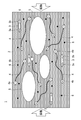
- FIG. 1 is a schematic cross-sectional view showing a schematic configuration of the composite vibration damping material of the present invention.
- 2A is a schematic diagram showing the dimensional relationship of the acicular dielectric used in the present invention
- FIG. 2B shows the configuration of the acicular dielectric provided with a conductive layer on the surface of titanium dioxide.
- FIG. 2C is a schematic view showing the dimensional relationship of the piezoelectric fiber used in the present invention.
- a composite damping material 1 includes a polymer material 2 serving as a matrix, and a needle-like high dielectric constant dielectric 3 and a piezoelectric fiber 4 composed of an organic material.
- a flat filler 5 made of an inorganic material and conductive fine particles 6 are further mixed.
- the polymer material 2 serving as a matrix is not particularly limited, and various elastomers and polymer resins can be used.
- elastomers examples include acrylic rubber (ACR), butyl rubber (IIR), acrylonitrile-butadiene rubber (NBR), acrylonitrile-butadiene rubber (NBR / PVC) blended with vinyl chloride resin, styrene- Examples include butadiene rubber (SBR), butadiene rubber (BR), natural rubber (NR), isoprene rubber (IR), butyl rubber (IIR), ethylene propylene rubber (EPM), and chloroprene rubber (CR). Among these, from the viewpoint of improving weather resistance and abrasion resistance, it is preferable to use acrylonitrile-butadiene rubber (NBR / PVC) blended with a vinyl chloride resin.
- ACR acrylic rubber
- IIR acrylonitrile-butadiene rubber
- NBR acrylonitrile-butadiene rubber
- NBR / PVC acrylonitrile-butadiene rubber
- CR chloroprene rubber
- examples of the polymer resin that can be used in the present invention include polylactic acid resin, polyurethane resin, acrylate resin, epoxy resin, polypropylene resin, polycarbonate resin, polyester resin, polyether resin, vinyl acetate resin, and polymethacrylic acid.
- the acicular high dielectric constant dielectric (hereinafter referred to as “acicular dielectric”) 3 used in the present invention is made of acicular titanium dioxide (TiO 2 ), for example.
- acicular titanium dioxide TiO 2
- a rutile type can be suitably used as a crystal form of titanium dioxide.
- needle shape means a shape in which the length L 1 of the major axis is larger than the diameter L 2 of the minor axis, as shown in FIG. Means the same.
- the acicular dielectric 3 preferably has an aspect ratio, that is, a ratio (L 1 / L 2 ) between the major axis length L 1 and the minor axis diameter L 2 of 10 to 30.
- the aspect ratio of the acicular dielectric 3 is preferably as large (elongated) as possible from the viewpoint of increasing the generated electric energy and exhibiting a more effective vibration damping action in the low frequency region.
- the acicular dielectric 3 is unidirectional due to, for example, the stress caused by the pressure during particle production or the pressure during mixing (kneading) in the polymer material 2. It is thought that the so-called monodomain structure is suitable.
- Such a needle-like dielectric 3 is considered to have a molecular arrangement structure that exhibits a piezoelectric effect and in which the generated electric energy easily flows along the longitudinal direction of the particles.
- the conductive layer 30 can be provided on the surface of the above-described titanium dioxide of the acicular dielectric 3 as a nucleus.
- the conductor layer 30 By providing the conductor layer 30 on the surface of the titanium dioxide of the needle-shaped dielectric 3, the magnitude of the current flowing on the surface of the needle-shaped dielectric 3 can be increased, so that a smaller amount of the needle-shaped dielectric 3 is provided. Can effectively control vibration.
- the material of the conductor layer 30 is not particularly limited, but from the viewpoint of improving the conductivity with ease of production and a smaller amount, tin dioxide doped with antimony (Sb) (SnO 2 ) can be suitably used.
- the thickness of the conductor layer 30 is preferably set to 1 to 20 ⁇ m when printed.
- the thickness of the conductor layer 30 can be set to 0.1 to 100 ⁇ m in the case of vapor deposition.
- the resistivity of the acicular dielectric 3 according to the present invention is preferably 2 to 80 ⁇ ⁇ cm, more preferably 10 to 60 ⁇ ⁇ cm.
- the piezoelectric fiber 4 made of an organic material used in the present invention is not particularly limited, but for example, those made of cellulose can be suitably used.
- the piezoelectric fiber 4 powdery cellulose (cellulose powder) having a small aspect ratio can be used in addition to those having a large aspect ratio (cellulose fiber).
- Cellulose, which is wood, is known to have piezoelectricity, and the cellulose fiber (powder) used in the present invention also has piezoelectricity.
- the aspect ratio of the piezoelectric fiber 4 that is, the ratio of the major axis length l 1 to the minor axis diameter l 2 (l 1 / l 2 ) (see FIG. 2 (c)) is generated based on the electric dipole. From the viewpoint of increasing the electrical energy to be applied and from the viewpoint of exhibiting more effective vibration damping action in the low frequency region, it is preferable to use a fiber shape that is as large as possible (elongated). However, considering that it is practically difficult to manufacture a fiber having an aspect ratio exceeding 10, it is more preferable to use a piezoelectric fiber 4 having an aspect ratio of 2 to 10.
- the compounding amount of the acicular dielectric 3 in the composite damping material 1 is not particularly limited, but is preferably set to 3 to 7% by weight. If the blending amount of the acicular dielectric 3 is less than 3% by weight, a sufficient vibration damping effect cannot be obtained, while if it exceeds 7% by weight, it becomes brittle after molding, which is not preferable.
- the blending amount of the piezoelectric fiber 4 made of an organic material in the composite damping material 1 is not particularly limited, but is preferably set to 4 to 10% by weight, more preferably 8% by weight. ⁇ 10% by weight.
- the blending amount of the piezoelectric fiber 4 made of an organic material is less than 4% by weight, a sufficient vibration damping effect cannot be achieved, and when it exceeds 10% by weight, it is difficult to uniformly disperse. Therefore, it is not preferable.
- the flat filler 5 which consists of inorganic materials, and the electroconductive fine particles 6 can be mix
- the flat filler 5 made of an inorganic material used in the present invention is intended to further improve the vibration damping capability and obtain desired mechanical properties (such as elastic modulus) as the entire composite material.
- a flat filler 5 what consists of layered mica (mica), for example can be used suitably.
- the blending amount of the filler 5 made of an inorganic material is not particularly limited, but is preferably set to 10% by weight to 30% by weight in view of the above-described purpose.
- the conductive fine particles 6 used in the present invention are for improving and adjusting the conductivity of the composite material as a whole.
- those previously added to the polymer material 2 can be used.
- the blending amount of the conductive fine particles 6 in the composite vibration damping material 1 is not particularly limited, but is preferably set to 5% by weight to 20% by weight in view of the above-described object.
- An ordinary method may be used to obtain the composite vibration damping material 1 and the molded body thereof according to the present invention. That is, a predetermined amount of the above-described acicular dielectric 3, piezoelectric fiber 4 made of an organic material, flat filler 5 made of an inorganic material, and conductive fine particles 6 are added to the polymer material 2 for the matrix. Kneading at a predetermined temperature, for example, after hot roll press molding, it may be cut into a predetermined size.
- the composite vibration damping material 1 of the present invention can be used as molded articles having various shapes.
- various shapes such as a disk shape, a cylindrical shape, a rectangular parallelepiped shape, a polyhedron shape, and a spherical shape can be used.
- it can be formed into a fiber and used as a cloth or used as a non-woven fabric.
- FIG. 3 is a schematic cross-sectional view showing a charge generation state when vibration is applied to the composite vibration damping material of the present invention.
- FIGS. 4 (a) to 4 (c) are schematic views showing the principle of the present invention. is there.
- the vibration energy causes displacement between layers in the flat filler 5 made of an inorganic material in the polymer material 2, and heat is generated by this mechanical action. Occurs and absorbs vibration.
- a potential difference is periodically generated between the both ends of the piezoelectric fiber 4 in the polymer material 2 due to the piezoelectric effect (electric dipoles 4 a and 4 b).
- the electric dipoles 4a and 4b generated in the piezoelectric fiber 4 increase.
- an alternating current caused by the electric dipoles 4a and 4b generated in a large number of piezoelectric fibers 4 flows through a conductive path in the composite material (compound), and electric energy by the alternating current is consumed as Joule heat, The vibration energy in the composite damping material 1 is attenuated.
- a potential difference is periodically generated between both ends (electric dipoles 3a and 3b).
- electric dipoles 4a and 4b generated in the piezoelectric fiber 4 are present in the vicinity of the acicular dielectric 3, so that As shown in FIG. 4 (b), the acicular dielectric 3 is disposed in the electric field F generated by the electric dipoles 4a and 4b.
- electric dipoles 3 c and 3 d caused by interface polarization are generated at the interface between the acicular dielectric 3 and the polymer material 2.
- An electric circuit is formed on the surface of the needle-shaped dielectric 3 by the electric dipoles 3a and 3d and the electric dipoles 3b and 3c generated in the needle-shaped dielectric 3, and an alternating current is generated on the surface of the needle-shaped dielectric 3. Flows. As a result, the electric energy due to the alternating current on the surface of the needle-like dielectric 3 is consumed as Joule heat, and the vibration energy in the composite vibration damping material 1 is attenuated.
- the electric dipoles 3a and 3b due to the piezoelectric effect are generated in the acicular dielectric 3 during vibration, and further, the electric dipoles 4a and 4b generated in the piezoelectric fiber 4 are generated. Since the resulting electric dipoles 3c and 3d are generated, a large current flows due to the electric dipoles 3a to 3d on the surface of the conductive acicular dielectric 3, and this electric energy is converted into Joule heat. A large amount is consumed and vibration is absorbed.
- the vibration energy is attenuated by the synergistic effect of the piezoelectric fibers 4 and the electric dipoles 3a to 3d of the needle-like dielectric 3, so that a more effective damping action can be achieved compared to the prior art. It can be demonstrated.
- Example 1 Damping Effect of Piezoelectric Fiber Consisting of Needle-like High Dielectric Constant and Organic Material ⁇ Example 1> A sample of the composite damping material of Example 1 was prepared using the following materials.
- As the polymer material for the matrix acrylonitrile-butadiene rubber (NBR / PVC: trade name NBRPVC601A manufactured by INB Planning) blended with vinyl chloride resin was used. Conductive particles made of carbon black are added to the polymer material.
- NBR / PVC trade name NBRPVC601A manufactured by INB Planning
- acicular high dielectric constant dielectric acicular titanium dioxide fine particles having a conductive layer (trade name: FT-4000, manufactured by Ishihara Sangyo Co., Ltd., major axis length: 10 ⁇ m, minor axis diameter: 0.5 ⁇ m, aspect ratio : 20) was used.
- a piezoelectric fiber made of an organic material a cellulose fiber having an aspect ratio of 2.11 (trade name: Solka Flock # 100, manufactured by Imazu Pharmaceutical Co., Ltd., major axis length: 40 ⁇ m, minor axis diameter: 19 ⁇ m) was used.
- As the flat filler layered mica (trade name, Clarite Mica Kuraray Co., Ltd.) was used.
- the layered mica is contained in the organic composite material for imparting vibration suppression at a certain blending ratio together with the processing aid.
- NBR / PVC 47.4% by weight (of which conductive fine particles 14.2% by weight), 43.8% by weight of vibration-damping organic composite material (of which 21.5% by weight of layered mica) and acicular dioxide dioxide Titanium fine particles 3.1% by weight, cellulose fiber 4.3% by weight and cross-linking agent 1.4% by weight were added and kneaded at a temperature of 140 ° C. After hot roll press molding, cut into a size of 10 mm ⁇ 200 mm. Thus, a test film having a thickness of 1 mm was obtained.
- Example 1 includes both acicular titanium dioxide fine particles and cellulose fibers in a polymer material as a matrix.
- Comparative Example 2 only the needle-like titanium dioxide fine particles are contained in the polymer material serving as a matrix, and cellulose fibers are not contained.
- Example 1 in which both the needle-like titanium dioxide fine particles and the cellulose fiber were mixed in the polymer material serving as the matrix was obtained as either of the needle-like titanium dioxide fine particles and the cellulose fiber.
- the loss tangent is clearly larger than that of Comparative Example 1 that does not include the above and Comparative Example 2 in which only acicular titanium dioxide fine particles are mixed.
- Example 2 Dependence of Piezoelectric Fiber Aspect Ratio on Damping Effect ⁇ Example 2> A sample of the composite damping material of Example 2 was prepared using the following materials.
- As the polymer material for the matrix acrylonitrile-butadiene rubber (NBR / PVC: trade name NBRPVC601A manufactured by INB Planning) blended with vinyl chloride resin was used. Conductive particles made of carbon black are added to the polymer material.
- acicular high dielectric constant dielectric acicular titanium dioxide fine particles having a conductive layer (trade name: FT-4000, manufactured by Ishihara Sangyo Co., Ltd., major axis length: 10 ⁇ m, minor axis diameter: 0.5 ⁇ m, aspect ratio : 20) was used.
- a piezoelectric fiber made of an organic material a cellulose fiber having an aspect ratio of 2.11 (trade name: Solka Flock # 100, manufactured by Imazu Pharmaceutical Co., Ltd., major axis length: 40 ⁇ m, minor axis diameter: 19 ⁇ m) was used.
- layered mica trade name, Clarite Mica Kuraray Co., Ltd.
- NBR / PVC 48% by weight (of which conductive fine particles are 15% by weight), the above-mentioned acicular titanium dioxide fine particles of 3.1% by weight, cellulose fiber 4.3% by weight, mica 20% by weight, vibration suppression 20% by weight of organic composite material, 3.1% by weight of processing aid and 1.5% by weight of cross-linking agent are added and kneaded at a temperature of 140 ° C. After hot roll press molding, the size is 10 mm ⁇ 200 mm. Cut to obtain a test film having a thickness of 1 mm.
- Example 3 Other than using piezoelectric fiber made of organic material, cellulose fiber with aspect ratio of 3.44 (trade name: Solka Flock # 40, Imazu Pharmaceutical Co., Ltd., major axis length: 55 ⁇ m, minor axis diameter: 16 ⁇ m) A sample of damping material was prepared under the same conditions as in Example 2.
- Example 4 Other than using piezoelectric fiber made of organic material, cellulose fiber with an aspect ratio of 6.22 (trade name Solkaflock # 10, Imazu Pharmaceutical Co., Ltd., major axis length: 100 ⁇ m, minor axis diameter: 16 ⁇ m) A sample of damping material was prepared under the same conditions as in Example 2.
- Example 3 A sample of damping material was prepared under the same conditions as in Example 2 except that the above-mentioned NBR / PVC was not added with piezoelectric fibers made of acicular titanium dioxide fine particles and organic material. This vibration damping material contains 40% by weight of conductive fine particles.
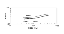
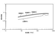
- the damping materials of Examples 2 to 4 have a loss factor more than twice that of the damping material of Comparative Example 3 in the low frequency region of about 60 Hz to about 500 Hz.
- the vibration damping materials of Examples 2 to 4 are in descending order of the aspect ratio of the cellulose fiber that is a piezoelectric fiber in a low frequency region of about 60 Hz to about 500 Hz, that is, Example 4, Example 3,
- the loss factor increased in the order of Example 2.
- this tendency was not changed even in a frequency region exceeding 500 Hz. From this result, it is understood that greater electrical energy is generated in the piezoelectric fiber by increasing the aspect ratio of the piezoelectric fiber.
- SYMBOLS 1 Composite damping material, 2 ... Polymer material, 3 ... Acicular high dielectric constant dielectric, 4 ... Piezoelectric fiber, 5 ... Flat filler, 6 ... Conductive fine particle
Abstract
従来技術に比べてより効果的な制振作用を発揮することができる制振材料を提供する。 本発明の複合制振材料1は、マトリックスとなる高分子材料2中に、二酸化チタンからなる針状の高誘電率誘電体3と、有機材料からなる圧電性繊維4とが混合されているものであり、好ましくは、さらに、無機材料からなる扁平状のフィラー5と、導電性微粒子6とが混合されているものである。圧電性繊維4としては、セルロースファイバーからなるものを好適に用いることができる。
Description
本発明は、振動エネルギーを電気エネルギーに変換して振動を減衰させる制振材料に関し、特に、機器の防振、騒音の吸収等に利用される複合制振材料に関する。
近年、産業機械、輸送機関の発達、家電用品の普及により、各種機器より発生する振動、騒音が健康管理または環境保全の観点から問題視されるに至っている。例えば、輸送機関、とりわけ鉄道の高速化による振動・騒音、高速道路、橋梁での自動車等の車輌による振動・騒音、また、オーディオ機器、パーソナルコンピュータ等の各種精密機械の普及に伴なう振動、特に低周波の振動が社会問題として取り上げられるようになり、その防止低減対策が今後の社会生活にとって不可欠な状況となっている。
従来、振動、騒音を防止するためには、(1)質量を増加させ、剛性を高めること、(2)共振を回避すること、(3)振動を減衰させることの三点が重要であるとされている(新素材ハンドフックp235(丸善)参照)。
前記(1)、(2)の振動を起こさせないようにするための剛構造設計に対し、前記(3)は、柔構造というべきものであり、自由に振動を起こさせてその後速やかに減衰させるのがよいとする考え方であり、かかる振動減衰には、振動体の有する振動エネルギーを熱に変えて消費することにより振幅を急速に減少させ振動を止める手法が提案され、また、実施にも移されている。特に、材料自体が有する減衰能を利用する制振材料が各種開発されてきている。
これらのうち、例えば、非圧電性の有機高分子マトリックスに圧電性、誘電性、導電性を有する低分子化合物を分散させた有機高分子系制振材料が提案されている。このような制振材料の作用は、従来の制振作用の原理とは異なる原理によるもので、振動エネルギーを一旦電気エネルギーに変換し、次いで、熱エネルギーに変換して消費することにより振動を減衰させるとするものであり、圧電・導電効果に基づく電気エネルギー損失が加わるため、より効率的な振動減衰が可能になるとされている(例えば、特許文献1、特許文献2参照)。
一方、例えば半導体製造装置等において微細な加工を行う場合等において、より効果的な制振作用が求められており、種々の技術分野において制振材料の研究開発が進展している(例えば、特許文献3参照)。
さらに、近年では、地震の際に制振を行う手段として、簡素な構成で且つ少ない材料でより効果的な制振作用が得られるものが求められている。
さらに、近年では、地震の際に制振を行う手段として、簡素な構成で且つ少ない材料でより効果的な制振作用が得られるものが求められている。
本発明は、このような従来の技術の課題を考慮してなされたもので、その目的とするところは、低周波領域においてより効果的な制振作用を発揮することができる複合制振材料を提供することにある。
上記目的を解決するため、本発明者は鋭意研究を重ねた結果、マトリックスとなる高分子材料中に特に針状の高誘電率誘電体と有機材料からなる圧電性繊維とを混合することで低周波振動に対する非常に効果的な制振材料が得られることを見い出し、本発明を完成するに到った。
かかる知見に基づいてなされた本発明は、マトリックスとなる高分子材料中に、針状の高誘電率誘電体と、有機材料からなる圧電性繊維とが混合されている複合制振材料である。
また、本発明は、マトリックスとなる高分子材料中に、針状の高誘電率誘電体と、有機材料からなる圧電性繊維と、無機材料からなる扁平状のフィラーと、導電性微粒子とが混合されている複合制振材料である。
本発明では、前記針状の高誘電率誘電体が、二酸化チタンからなる場合にも効果的である。
本発明では、前記針状の高誘電率誘電体が、針状の二酸化チタンからなる核体の表面に、導電体層が設けられている場合にも効果的である。
本発明では、前記有機材料からなる圧電性繊維が、セルロースファイバーからなる場合にも効果的である。
また、本発明は、マトリックスとなる高分子材料中に、針状の高誘電率誘電体と、有機材料からなる圧電性繊維と、無機材料からなる扁平状のフィラーと、導電性微粒子とが混合されている複合制振材料である。
本発明では、前記針状の高誘電率誘電体が、二酸化チタンからなる場合にも効果的である。
本発明では、前記針状の高誘電率誘電体が、針状の二酸化チタンからなる核体の表面に、導電体層が設けられている場合にも効果的である。
本発明では、前記有機材料からなる圧電性繊維が、セルロースファイバーからなる場合にも効果的である。
本発明によれば、低周波領域においてより効果的な制振作用を発揮することができる制振材料を提供することができる。
以下、本発明の好ましい実施の形態を図面を参照して詳細に説明する。
図1は、本発明の複合制振材料の概略構成を示す断面模式図である。また、図2(a)は、本発明に用いる針状誘電体の寸法関係を示す模式図、図2(b)は、二酸化チタンの表面に導電体層を設けた針状誘電体の構成を示す断面図、図2(c)は、本発明に用いる圧電性繊維の寸法関係を示す模式図である。
図1は、本発明の複合制振材料の概略構成を示す断面模式図である。また、図2(a)は、本発明に用いる針状誘電体の寸法関係を示す模式図、図2(b)は、二酸化チタンの表面に導電体層を設けた針状誘電体の構成を示す断面図、図2(c)は、本発明に用いる圧電性繊維の寸法関係を示す模式図である。
図1に示すように、本発明の複合制振材料1は、マトリックスとなる高分子材料2中に、針状の高誘電率誘電体3と、有機材料からなる圧電性繊維4とが混合されているものであり、好ましくは、さらに、無機材料からなる扁平状のフィラー5と、導電性微粒子6とが混合されているものである。
本発明の場合、マトリックスとなる高分子材料2は特に限定されることはなく、種々のエラストマーや高分子樹脂を用いることができる。
本発明の場合、マトリックスとなる高分子材料2は特に限定されることはなく、種々のエラストマーや高分子樹脂を用いることができる。
本発明に用いることができるエラストマーとしては、例えば、アクリルゴム(ACR)、ブチルゴム(IIR)、アクリロニトリル-ブタジエンゴム(NBR)、塩化ビニル樹脂をブレンドしたアクリロニトリル-ブタジエンゴム(NBR/PVC)、スチレン-ブタジエンゴム(SBR)、ブタジエンゴム(BR)、天然ゴム(NR)、イソプレンゴム(IR)、ブチルゴム(IIR)、エチレンプロピレンゴム(EPM)、クロロプレンゴム(CR)、等があげられる。
これらのうちでも、耐候性及び耐摩耗性を向上させる観点からは、塩化ビニル樹脂をブレンドしたアクリロニトリル-ブタジエンゴム(NBR/PVC)を用いることが好ましい。
これらのうちでも、耐候性及び耐摩耗性を向上させる観点からは、塩化ビニル樹脂をブレンドしたアクリロニトリル-ブタジエンゴム(NBR/PVC)を用いることが好ましい。
一方、本発明に用いることができる高分子樹脂としては、例えば、ポリ乳酸樹脂、ポリウレタン樹脂、アクリレート樹脂、エポキシ樹脂、ポリプロピレン樹脂、ポリカーボネート樹脂、ポリエステル樹脂、ポリエーテル樹脂、酢酸ビニル樹脂、ポリメタクリル酸メチル樹脂、ポリフッ化ビニリデン樹脂、ポリスチレン樹脂、エチレン-酢酸ビニル共重合体、エチレン-塩化ビニル共重合体、エチレン-メタアクリレート共重合体、アクリロニトリル-スチレン共重合体、アクリロニトリル-ブタジエン-スチレン共重合体、塩素化ポリエチレン、塩素化ポリプロピレン、塩素化ポリブチレン等があげられる。
本発明に用いる針状の高誘電率誘電体(以下、「針状誘電体」という。)3は、例えば針状の二酸化チタン(TiO2)からなるものである。なお、二酸化チタンの結晶形態としては、ルチル型のものを好適に用いることができる。
本明細書において、「針状」とは、図2(a)に示すように、長軸の長さL1が、短軸の径L2より大きい形状を意味するものとし、紡錘状、棒状と同じ意味である。
本明細書において、「針状」とは、図2(a)に示すように、長軸の長さL1が、短軸の径L2より大きい形状を意味するものとし、紡錘状、棒状と同じ意味である。
ここで、針状誘電体3としては、アスペクト比、すなわち、長軸の長さL1と短軸の径L2の比(L1/L2)を、10~30とすることが好ましい。
針状誘電体3のアスペクト比は、発生する電気エネルギーを大きくする観点及び低周波領域においてより効果的な制振作用を発揮させる観点からは、できるだけ大きい(細長い)ことが好ましい。
針状誘電体3のアスペクト比は、発生する電気エネルギーを大きくする観点及び低周波領域においてより効果的な制振作用を発揮させる観点からは、できるだけ大きい(細長い)ことが好ましい。
ただし、アスペクト比が30を超えるものを製造することは実際上困難である。
他方、針状誘電体3のアスペクト比が10未満の場合には、十分な電気エネルギーを発生させることができない。
他方、針状誘電体3のアスペクト比が10未満の場合には、十分な電気エネルギーを発生させることができない。
この針状誘電体3は、詳細は明らかではないが、例えば、粒子製造時の圧力や、高分子材料2中に混合(混練)する際の圧力に起因する応力によって、分子配列が一方向に向くいわゆるモノドメイン構造となっていると考えられる。
そして、このような針状誘電体3は、圧電効果を発現し、しかも発生した電気エネルギーが粒子の長手方向に沿って流れやすい分子の配列構造となっていると考えられる。
そして、このような針状誘電体3は、圧電効果を発現し、しかも発生した電気エネルギーが粒子の長手方向に沿って流れやすい分子の配列構造となっていると考えられる。
本発明においては、図2(b)に示すように、上述した針状誘電体3の二酸化チタンを核体としてその表面に導電体層30を設けることもできる。
針状誘電体3の二酸化チタンの表面に導電体層30を設けることにより、針状誘電体3の表面に流れる電流の大きさを大きくすることができるので、より少ない量の針状誘電体3によって効果的な制振を行うことができる。
針状誘電体3の二酸化チタンの表面に導電体層30を設けることにより、針状誘電体3の表面に流れる電流の大きさを大きくすることができるので、より少ない量の針状誘電体3によって効果的な制振を行うことができる。
本発明の場合、導電体層30の材料としては特に限定されることはないが、製造のしやすさ及びより少ない量で導電性を向上させる観点からは、アンチモン(Sb)をドープした二酸化スズ(SnO2)を好適に用いることができる。
この場合、導電体層30の厚さは、プリントによる場合には、1~20μmに設定することが好ましい。
他方、導電体層30の厚さは、蒸着による場合には、0.1~100μmまで設定することができる。
他方、導電体層30の厚さは、蒸着による場合には、0.1~100μmまで設定することができる。
一方、本発明の針状誘電体3の抵抗率(導電体層30を形成したものも含む)は、2~80Ω・cmのものが好ましく、より好ましくは10~60Ω・cmである。
本発明に用いる有機材料からなる圧電性繊維4は、特に限定されることはないが、例えばセルロースからなるものを好適に用いることができる。
この圧電性繊維4は、アスペクト比の大きいもの(セルロースファイバー)の他、アスペクト比の小さい粉末状のセルロース(セルロースパウダー)を用いることもできる。
木材であるセルロースは、圧電性を有することが知られており、本発明に用いるセルロースファイバー(パウダー)も、圧電性を有している。
この圧電性繊維4は、アスペクト比の大きいもの(セルロースファイバー)の他、アスペクト比の小さい粉末状のセルロース(セルロースパウダー)を用いることもできる。
木材であるセルロースは、圧電性を有することが知られており、本発明に用いるセルロースファイバー(パウダー)も、圧電性を有している。
圧電性繊維4のアスペクト比、すなわち、長軸の長さl1と短軸の径l2の比(l1/l2)については(図2(c)参照)、電気双極子に基づき発生する電気エネルギーを大きくする観点及び低周波領域においてより効果的な制振作用を発揮させる観点からは、できるだけ大きい(細長い)ファイバー状のものを用いることが好ましい。
ただし、アスペクト比が10を超えるものを製造することは実際上困難であることを考慮すると、圧電性繊維4としては、アスペクト比が2~10のものを用いることがより好ましい。
ただし、アスペクト比が10を超えるものを製造することは実際上困難であることを考慮すると、圧電性繊維4としては、アスペクト比が2~10のものを用いることがより好ましい。
本発明の場合、複合制振材料1における針状誘電体3の配合量は、特に限定されることはないが、3重量%~7重量%に設定することが好ましい。
針状誘電体3の配合量が3重量%未満であると、十分な制振効果を奏することができず、他方、7重量%を超えると、成形後に脆くなるため好ましくない。
一方、複合制振材料1における有機材料からなる圧電性繊維4の配合量は、特に限定されることはないが、4重量%~10重量%に設定することが好ましく、より好ましくは8重量%~10重量%である。
有機材料からなる圧電性繊維4の配合量が4重量%未満であると、十分な制振効果を奏することができず、他方、10重量%を超えると、均一に分散させることが困難であるため好ましくない。
針状誘電体3の配合量が3重量%未満であると、十分な制振効果を奏することができず、他方、7重量%を超えると、成形後に脆くなるため好ましくない。
一方、複合制振材料1における有機材料からなる圧電性繊維4の配合量は、特に限定されることはないが、4重量%~10重量%に設定することが好ましく、より好ましくは8重量%~10重量%である。
有機材料からなる圧電性繊維4の配合量が4重量%未満であると、十分な制振効果を奏することができず、他方、10重量%を超えると、均一に分散させることが困難であるため好ましくない。
本発明では、無機材料からなる扁平状のフィラー5と、導電性微粒子6は、必要に応じて配合させることができるものである。
本発明に用いる無機材料からなる扁平状のフィラー5は、制振能力をより向上させるとともに、複合材料全体として所望の機械的特性(弾性率等)を得るためのものである。
このような扁平状のフィラー5としては、例えば層状のマイカ(雲母)からなるものを好適に用いることができる。
本発明に用いる無機材料からなる扁平状のフィラー5は、制振能力をより向上させるとともに、複合材料全体として所望の機械的特性(弾性率等)を得るためのものである。
このような扁平状のフィラー5としては、例えば層状のマイカ(雲母)からなるものを好適に用いることができる。
本発明の場合、無機材料からなるフィラー5の配合量は、特に限定されることはないが、上述した目的を考慮すると、10重量%~30重量%に設定することが好ましい。
本発明に用いる導電性微粒子6は、複合材料全体としての導伝率を向上・調整するためのものである。
このような導電性微粒子6としては、例えばカーボンブラックからなるものを好適に用いることができる。
なお、導電性微粒子6としては、予め高分子材料2に添加されているものを使用することができる。
このような導電性微粒子6としては、例えばカーボンブラックからなるものを好適に用いることができる。
なお、導電性微粒子6としては、予め高分子材料2に添加されているものを使用することができる。
本発明の場合、複合制振材料1における導電性微粒子6の配合量は、特に限定されることはないが、上述した目的を考慮すると、5重量%~20重量%に設定することが好ましい。
本発明に係る複合制振材料1及びその成形体を得るには通常の方法を用いればよい。
すなわち、マトリックス用の高分子材料2に、上述した針状誘電体3、有機材料からなる圧電性繊維4、必要に応じて無機材料からなる扁平状のフィラー5、導電性微粒子6を所定量加えて所定温度で混練し、例えば熱ロールプレス成形後、所定の大きさに切断すればよい。
すなわち、マトリックス用の高分子材料2に、上述した針状誘電体3、有機材料からなる圧電性繊維4、必要に応じて無機材料からなる扁平状のフィラー5、導電性微粒子6を所定量加えて所定温度で混練し、例えば熱ロールプレス成形後、所定の大きさに切断すればよい。
本発明の複合制振材料1は、種々の形状の成形体として使用することができる。
例えば、フィルム状の成形体の他、円板形状や円柱形状、長方体形状、多面体形状、球形状等の種々の形状にして使用することができる。
また、繊維状に形成して布として使用したり、不織布として使用することもできる。
例えば、フィルム状の成形体の他、円板形状や円柱形状、長方体形状、多面体形状、球形状等の種々の形状にして使用することができる。
また、繊維状に形成して布として使用したり、不織布として使用することもできる。
図3は、本発明の複合制振材料に振動が加わった場合の電荷の発生状態を示す断面模式図であり、図4(a)~(c)は、本発明の原理を示す模式図である。
本発明の複合制振材料1に周期的な振動が加わると、その振動エネルギーにより、高分子材料2中の無機材料からなる扁平状のフィラー5において層間のずれが生じ、この機械的作用により熱が発生して振動を吸収する。
本発明の複合制振材料1に周期的な振動が加わると、その振動エネルギーにより、高分子材料2中の無機材料からなる扁平状のフィラー5において層間のずれが生じ、この機械的作用により熱が発生して振動を吸収する。
さらに、本発明においては、図3に示すように、高分子材料2中の圧電性繊維4に、その圧電効果によって、両端部間に周期的に電位差が生ずる(電気双極子4a、4b)。
この場合、圧電性繊維4のアスペクト比が大きくなるに従い、圧電性繊維4に発生する電気双極子4a、4bが増加するようになる。
そして、多数の圧電性繊維4に発生した電気双極子4a、4bに起因する交流電流が複合材料(コンパウンド)内の導電路を介して流れ、この交流電流による電気エネルギーがジュール熱として消費され、複合制振材料1における振動エネルギーが減衰する。
一方、針状誘電体3にも、その圧電効果によって、両端部間に周期的に電位差が生ずる(電気双極子3a、3b)。
この場合、圧電性繊維4のアスペクト比が大きくなるに従い、圧電性繊維4に発生する電気双極子4a、4bが増加するようになる。
そして、多数の圧電性繊維4に発生した電気双極子4a、4bに起因する交流電流が複合材料(コンパウンド)内の導電路を介して流れ、この交流電流による電気エネルギーがジュール熱として消費され、複合制振材料1における振動エネルギーが減衰する。
一方、針状誘電体3にも、その圧電効果によって、両端部間に周期的に電位差が生ずる(電気双極子3a、3b)。
加えて、本発明においては、図4(a)に示すように、針状誘電体3の近傍に、上記圧電性繊維4において発生した電気双極子4a、4bが存在することになるため、図4(b)に示すように、針状誘電体3が、電気双極子4a、4bによって生じた電界F内に配置される。
これにより、図4(c)に示すように、針状誘電体3と高分子材料2との界面に、界面分極に起因する電気双極子3c、3dが発生する。
これにより、図4(c)に示すように、針状誘電体3と高分子材料2との界面に、界面分極に起因する電気双極子3c、3dが発生する。
そして、針状誘電体3に発生した電気双極子3a及び3dと電気双極子3b及び3cによって、針状誘電体3の表面に電気的回路が形成され、針状誘電体3の表面に交流電流が流れる。
その結果、この針状誘電体3の表面の交流電流による電気エネルギーがジュール熱として消費され、複合制振材料1における振動エネルギーが減衰する。
その結果、この針状誘電体3の表面の交流電流による電気エネルギーがジュール熱として消費され、複合制振材料1における振動エネルギーが減衰する。
一般に、圧電効果を有する粒子を混合した圧電複合材料の抵抗をR、圧電粒子の容量をC、減衰させたい振動の振動数をωとすると、インピーダンスの整合条件として、R=1/ωCの条件が成立するときに、最も迅速に振動が減衰することが知られている。
したがって、本発明において、複合制振材料1の固有振動数に対応する適切な導電率を設定することによって所望の制振効果を得ることができる。
したがって、本発明において、複合制振材料1の固有振動数に対応する適切な導電率を設定することによって所望の制振効果を得ることができる。
以上述べたように本発明の場合、加振時に、針状誘電体3において、その圧電効果による電気双極子3a、3bが発生し、さらに圧電性繊維4において発生した電気双極子4a、4bに起因する電気双極子3c、3dが発生することから、導電性の針状誘電体3の表面にこれら双方の電気双極子3a~3dに起因して大きな電流が流れ、この電気エネルギーがジュール熱として多量に消費されて振動が吸収される。
このように、本発明によれば、圧電性繊維4及び針状誘電体3の電気双極子3a~3dの相乗効果による振動エネルギーの減衰によって、従来技術に比べてより効果的な制振作用を発揮させることができる。
しかも、針状になることで界面分極による電気双極子は低周波(500Hz未満)で生ずることから(例えば、特開平10-312191号公報参照)、本発明によれば、低周波で振動する機器等に対して最適の条件で制振を行う複合制振材料を提供することができる。
さらに、無機材料からなる扁平状のフィラー5を混合することによって、この無機材料からなる扁平状のフィラー5の機械的作用による振動エネルギーの減衰と、上記圧電性繊維4及び針状誘電体3の電気双極子3a~3dの相乗効果による振動エネルギーの減衰とによって、より効果的な制振作用を発揮させることができ、また、導電性微粒子6を混合することにより、複合材料全体としての導伝率を向上・調整することができる。
さらに、無機材料からなる扁平状のフィラー5を混合することによって、この無機材料からなる扁平状のフィラー5の機械的作用による振動エネルギーの減衰と、上記圧電性繊維4及び針状誘電体3の電気双極子3a~3dの相乗効果による振動エネルギーの減衰とによって、より効果的な制振作用を発揮させることができ、また、導電性微粒子6を混合することにより、複合材料全体としての導伝率を向上・調整することができる。
以下、本発明を実施例に基づいて説明するが、本発明はこれらの実施例に限定されるものではない。
1.針状の高誘電率誘電体と有機材料からなる圧電性繊維による制振効果
<実施例1>
以下の各材料を用い、実施例1の複合制振材料の試料を作成した。
マトリックス用の高分子材料として、塩化ビニル樹脂をブレンドしたアクリロニトリル-ブタジエンゴム(NBR/PVC:商品名NBRPVC601A INBプランニング社製)を用いた。
この高分子材料には、カーボンブラックからなる導電性粒子が添加されている。
針状の高誘電率誘電体として、導電体層を有する針状の二酸化チタン微細粒子(商品名 FT-4000 石原産業社製、長軸長さ:10μm、短軸径:0.5μm、アスペクト比:20)を用いた。
有機材料からなる圧電性繊維として、アスペクト比が2.11のセルロースファイバー(商品名ソルカフロック#100 今津薬品工業社製、長軸長さ:40μm、短軸径:19μm)を用いた。
扁平状のフィラーとして、層状のマイカ(商品名クラライトマイカ クラレ社製)を用いた。
この層状のマイカは、制振付与用の有機複合材料に加工助剤とともに一定の配合比で含まれている。
NBR/PVC47.4重量%(うち導電性微粒子14.2重量%)に、制振付与用の有機複合材料43.8重量%(うち層状のマイカ21.5重量%)と、針状の二酸化チタン微細粒子3.1重量%と、セルロースファイバー4.3重量%と、架橋剤1.4重量%を加えて温度140℃で混練し、熱ロールプレス成形後、大きさ10mm×200mmに切断して厚さ1mmの試験用フィルムを得た。
この実施例1は、マトリックスとなる高分子材料中に、針状の二酸化チタン微細粒子と、セルロースファイバーの両方を含むものである。
<比較例1>
NBR/PVC51.2重量%(うち導電性微粒子15.0重量%)に、制振付与用の有機複合材料47.3重量%(うち層状のマイカ23.3重量%)と、架橋剤1.5重量%を加え、実施例1と同一の条件で制振材料の試料を作成した。
この比較例1は、マトリックスとなる高分子材料中に、針状の二酸化チタン微細粒子及びセルロースファイバーのいずれも含まないものである。
NBR/PVC51.2重量%(うち導電性微粒子15.0重量%)に、制振付与用の有機複合材料47.3重量%(うち層状のマイカ23.3重量%)と、架橋剤1.5重量%を加え、実施例1と同一の条件で制振材料の試料を作成した。
この比較例1は、マトリックスとなる高分子材料中に、針状の二酸化チタン微細粒子及びセルロースファイバーのいずれも含まないものである。
<比較例2>
NBR/PVC49.5重量%(うち導電性微粒子14.9重量%)に、制振付与用の有機複合材料45.7重量%(うち層状のマイカ22.5重量%)と、針状の二酸化チタン微細粒子3.3重量%と、架橋剤1.5重量%を加え、実施例1と同一の条件で制振材料の試料を作成した。
この比較例2は、マトリックスとなる高分子材料中に、針状の二酸化チタン微細粒子のみが含まれ、セルロースファイバーを含まないものである。
NBR/PVC49.5重量%(うち導電性微粒子14.9重量%)に、制振付与用の有機複合材料45.7重量%(うち層状のマイカ22.5重量%)と、針状の二酸化チタン微細粒子3.3重量%と、架橋剤1.5重量%を加え、実施例1と同一の条件で制振材料の試料を作成した。
この比較例2は、マトリックスとなる高分子材料中に、針状の二酸化チタン微細粒子のみが含まれ、セルロースファイバーを含まないものである。
《中央加振法による損失係数測定》
実施例1及び比較例1、2の試料について、中央加振法(10×200×0.8mm 12.35g鋼板)によって損失係数の周波数依存性を測定した。
測定系としては、発振器はType 2825、増幅器はType 2718、加振器はType 4809、加速度センサはType 8001で構成されるシステムを用い(いずれもB&K社製)、各機器の制御はパーソナルコンピュータを用いた。
この場合、共振周波数は、第1次~第7次まで測定した。この損失係数の測定結果を図5に示す。
実施例1及び比較例1、2の試料について、中央加振法(10×200×0.8mm 12.35g鋼板)によって損失係数の周波数依存性を測定した。
測定系としては、発振器はType 2825、増幅器はType 2718、加振器はType 4809、加速度センサはType 8001で構成されるシステムを用い(いずれもB&K社製)、各機器の制御はパーソナルコンピュータを用いた。
この場合、共振周波数は、第1次~第7次まで測定した。この損失係数の測定結果を図5に示す。
《動的粘弾性測定による損失正接測定》
実施例1及び比較例1、2の試料について、動的粘弾性測定装置(アイティ計測制御社製 DVA-200S)を用い、30℃~70℃における損失正接(Tanδ)を測定した。
この場合、振動周波数は、0.2Hz、1Hz、6Hzに変えて測定を行った。
その結果を図6~8に示す。
実施例1及び比較例1、2の試料について、動的粘弾性測定装置(アイティ計測制御社製 DVA-200S)を用い、30℃~70℃における損失正接(Tanδ)を測定した。
この場合、振動周波数は、0.2Hz、1Hz、6Hzに変えて測定を行った。
その結果を図6~8に示す。
《誘電分散による比誘電率並びに比誘電損率測定》
実施例1及び比較例1、2の試料について、上述した動的粘弾性測定装置を用い、比誘電率(e′)並びに比誘電損率(e″)の周波数依存性を測定した。
その結果を図9、図10に示す。
実施例1及び比較例1、2の試料について、上述した動的粘弾性測定装置を用い、比誘電率(e′)並びに比誘電損率(e″)の周波数依存性を測定した。
その結果を図9、図10に示す。
《評価》
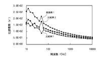
図5に示す、中央加振法による損失係数測定の結果においては、約300Hz~約5000Hzの周波数領域において、マトリックスとなる高分子材料中に針状の二酸化チタン微細粒子とセルロースファイバーの両方を混合した実施例1が、針状の二酸化チタン微細粒子及びセルロースファイバーのいずれも含まない比較例1、並びに、針状の二酸化チタン微細粒子のみを混合した比較例2に比べて明瞭に損失係数が大きくなっており、本発明の特徴である、針状の高誘電率誘電体と、有機材料からなる圧電性繊維の共存による相乗効果がはっきり現れている。
さらに、図6~図8に示される、周波数0.2Hz,1Hz,6Hzにおける動的粘弾性測定による損失正接(tanδ)-温度(T)変化のグラフでは、損失正接の温度変化がほぼ一定になる30℃―70℃の範囲において、マトリックスとなる高分子材料中に針状の二酸化チタン微細粒子とセルロースファイバーの両方を混合した実施例1が、針状の二酸化チタン微細粒子及びセルロースファイバーのいずれも含まない比較例1、並びに、針状の二酸化チタン微細粒子のみを混合した比較例2に比べて明瞭に損失正接が大きくなっており、ここでも本発明の特徴である、針状の高誘電率誘電体と、有機材料からなる圧電性繊維の共存による相乗効果がはっきり現れている。
この場合、周波数による、実施例1の損失正接と、比較例1及び比較例2の損失正接の差は、0.2Hz > 1Hz > 6Hzの順となっている。
このことから、本発明は、周波数の低い領域においてより大きな制振効果を発揮するものであることが見て取れる。
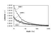
さらに、本発明が周波数の低い領域においてより大きな制振効果を発揮する点は、図10に示す比誘電損率測定のグラフにおいて、概ね500Hz以下の低周波数領域において、周波数が小さくなるに従い、実施例1と、比較例1及び比較例2における比誘電損率(e″)の差が大きくなっていることからも明らかである。
図5に示す、中央加振法による損失係数測定の結果においては、約300Hz~約5000Hzの周波数領域において、マトリックスとなる高分子材料中に針状の二酸化チタン微細粒子とセルロースファイバーの両方を混合した実施例1が、針状の二酸化チタン微細粒子及びセルロースファイバーのいずれも含まない比較例1、並びに、針状の二酸化チタン微細粒子のみを混合した比較例2に比べて明瞭に損失係数が大きくなっており、本発明の特徴である、針状の高誘電率誘電体と、有機材料からなる圧電性繊維の共存による相乗効果がはっきり現れている。
さらに、図6~図8に示される、周波数0.2Hz,1Hz,6Hzにおける動的粘弾性測定による損失正接(tanδ)-温度(T)変化のグラフでは、損失正接の温度変化がほぼ一定になる30℃―70℃の範囲において、マトリックスとなる高分子材料中に針状の二酸化チタン微細粒子とセルロースファイバーの両方を混合した実施例1が、針状の二酸化チタン微細粒子及びセルロースファイバーのいずれも含まない比較例1、並びに、針状の二酸化チタン微細粒子のみを混合した比較例2に比べて明瞭に損失正接が大きくなっており、ここでも本発明の特徴である、針状の高誘電率誘電体と、有機材料からなる圧電性繊維の共存による相乗効果がはっきり現れている。
この場合、周波数による、実施例1の損失正接と、比較例1及び比較例2の損失正接の差は、0.2Hz > 1Hz > 6Hzの順となっている。
このことから、本発明は、周波数の低い領域においてより大きな制振効果を発揮するものであることが見て取れる。
さらに、本発明が周波数の低い領域においてより大きな制振効果を発揮する点は、図10に示す比誘電損率測定のグラフにおいて、概ね500Hz以下の低周波数領域において、周波数が小さくなるに従い、実施例1と、比較例1及び比較例2における比誘電損率(e″)の差が大きくなっていることからも明らかである。
2.制振効果に対する圧電性繊維のアスペクト比依存性
<実施例2>
以下の各材料を用い、実施例2の複合制振材料の試料を作成した。
マトリックス用の高分子材料として、塩化ビニル樹脂をブレンドしたアクリロニトリル-ブタジエンゴム(NBR/PVC:商品名NBRPVC601A INBプランニング社製)を用いた。
この高分子材料には、カーボンブラックからなる導電性粒子が添加されている。
針状の高誘電率誘電体として、導電体層を有する針状の二酸化チタン微細粒子(商品名 FT-4000 石原産業社製、長軸長さ:10μm、短軸径:0.5μm、アスペクト比:20)を用いた。
有機材料からなる圧電性繊維として、アスペクト比が2.11のセルロースファイバー(商品名ソルカフロック#100 今津薬品工業社製、長軸長さ:40μm、短軸径:19μm)を用いた。
扁平状のフィラーとして、層状のマイカ(商品名クラライトマイカ クラレ社製)を用いた。
上述したNBR/PVC48重量%(うち導電性微粒子15重量%)に、上述した針状の二酸化チタン微細粒子3.1重量%と、セルロースファイバー4.3重量%と、マイカ20重量%、制振付与用の有機複合材料20重量%と、加工助剤3.1重量%と、架橋剤1.5重量%を加えて温度140℃で混練し、熱ロールプレス成形後、大きさ10mm×200mmに切断して厚さ1mmの試験用フィルムを得た。
<実施例3>
有機材料からなる圧電性繊維として、アスペクト比が3.44のセルロースファイバー(商品名ソルカフロック#40 今津薬品工業社製、長軸長さ:55μm、短軸径:16μm)を用いた他は実施例2と同一の条件で制振材料の試料を作成した。
有機材料からなる圧電性繊維として、アスペクト比が3.44のセルロースファイバー(商品名ソルカフロック#40 今津薬品工業社製、長軸長さ:55μm、短軸径:16μm)を用いた他は実施例2と同一の条件で制振材料の試料を作成した。
<実施例4>
有機材料からなる圧電性繊維として、アスペクト比が6.22のセルロースファイバー(商品名ソルカフロック#10 今津薬品工業社製、長軸長さ:100μm、短軸径:16μm)を用いた他は実施例2と同一の条件で制振材料の試料を作成した。
有機材料からなる圧電性繊維として、アスペクト比が6.22のセルロースファイバー(商品名ソルカフロック#10 今津薬品工業社製、長軸長さ:100μm、短軸径:16μm)を用いた他は実施例2と同一の条件で制振材料の試料を作成した。
<比較例3>
上述したNBR/PVCに、針状の二酸化チタン微細粒子及び有機材料からなる圧電性繊維を加えることなく、その他は実施例2と同一の条件で制振材料の試料を作成した。
この制振材料には、導電性微粒子が40重量%含まれている。
上述したNBR/PVCに、針状の二酸化チタン微細粒子及び有機材料からなる圧電性繊維を加えることなく、その他は実施例2と同一の条件で制振材料の試料を作成した。
この制振材料には、導電性微粒子が40重量%含まれている。
《中央加振法による損失係数測定》
実施例2~4及び比較例3の試料について、中央加振法(10×200×0.8mm 12.35g鋼板)によって損失係数の周波数依存性を測定した。
測定系としては、発振器はType 2825、増幅器はType 2718、加振器はType 4809、加速度センサはType 8001で構成されるシステムを用い(いずれもB&K社製)、各機器の制御はパーソナルコンピュータを用いた。
この場合、共振周波数は、第1次~第7次まで測定した。この損失係数の測定結果を図11に示す。
実施例2~4及び比較例3の試料について、中央加振法(10×200×0.8mm 12.35g鋼板)によって損失係数の周波数依存性を測定した。
測定系としては、発振器はType 2825、増幅器はType 2718、加振器はType 4809、加速度センサはType 8001で構成されるシステムを用い(いずれもB&K社製)、各機器の制御はパーソナルコンピュータを用いた。
この場合、共振周波数は、第1次~第7次まで測定した。この損失係数の測定結果を図11に示す。
《評価》
図11から明らかなように、実施例2~実施例4の制振材料は、約60Hz~約500Hzの低周波数領域において、比較例3の制振材料に比べて2倍以上の損失係数が得られ、これにより本発明の効果を実証することができた。
また、実施例2~実施例4の制振材料は、約60Hz~約500Hzの低周波数領域において、圧電性繊維であるセルロースファイバーのアスペクト比が大きい順、すなわち、実施例4、実施例3、実施例2の順で損失係数が大きくなった。
さらに、500Hzを超える周波数領域においても、この傾向は変わらなかった。
この結果から、圧電性繊維のアスペクト比を大きくすることによって、圧電性繊維において、より大きな電気エネルギーが発生していることが理解される。
1…複合制振材料、2…高分子材料、3…針状の高誘電率誘電体、4…圧電性繊維、5…扁平状のフィラー、6…導電性微粒子
Claims (5)
- マトリックスとなる高分子材料中に、針状の高誘電率誘電体と、有機材料からなる圧電性繊維とが混合されている複合制振材料。
- マトリックスとなる高分子材料中に、針状の高誘電率誘電体と、有機材料からなる圧電性繊維と、無機材料からなる扁平状のフィラーと、導電性微粒子とが混合されている複合制振材料。
- 前記針状の高誘電率誘電体が、二酸化チタンからなる請求項1又は2のいずれか1項記載の複合制振材料。
- 前記針状の高誘電率誘電体が、針状の二酸化チタンからなる核体の表面に、導電体層が設けられている請求項1乃至3のいずれか1項記載の複合制振材料。
- 前記有機材料からなる圧電性繊維が、セルロースファイバーからなる請求項1乃至4のいずれか1項記載の複合制振材料。
Priority Applications (3)
| Application Number | Priority Date | Filing Date | Title |
|---|---|---|---|
| CN201380075116.5A CN105190086A (zh) | 2013-03-27 | 2013-09-27 | 复合减震材料 |
| EP13880324.2A EP2980443A4 (en) | 2013-03-27 | 2013-09-27 | COMPOSITE DAMPING MATERIAL |
| US14/867,492 US20160040744A1 (en) | 2013-03-27 | 2015-09-28 | Composite damping material |
Applications Claiming Priority (2)
| Application Number | Priority Date | Filing Date | Title |
|---|---|---|---|
| JP2013-067226 | 2013-03-27 | ||
| JP2013067226A JP6180148B2 (ja) | 2012-03-28 | 2013-03-27 | 複合制振材料 |
Related Child Applications (1)
| Application Number | Title | Priority Date | Filing Date |
|---|---|---|---|
| US14/867,492 Continuation US20160040744A1 (en) | 2013-03-27 | 2015-09-28 | Composite damping material |
Publications (1)
| Publication Number | Publication Date |
|---|---|
| WO2014155786A1 true WO2014155786A1 (ja) | 2014-10-02 |
Family
ID=51625712
Family Applications (1)
| Application Number | Title | Priority Date | Filing Date |
|---|---|---|---|
| PCT/JP2013/076310 WO2014155786A1 (ja) | 2013-03-27 | 2013-09-27 | 複合制振材料 |
Country Status (5)
| Country | Link |
|---|---|
| US (1) | US20160040744A1 (ja) |
| EP (1) | EP2980443A4 (ja) |
| CN (1) | CN105190086A (ja) |
| TW (1) | TW201437002A (ja) |
| WO (1) | WO2014155786A1 (ja) |
Cited By (3)
| Publication number | Priority date | Publication date | Assignee | Title |
|---|---|---|---|---|
| CN108885862A (zh) * | 2016-03-31 | 2018-11-23 | 马自达汽车株式会社 | 吸声材料 |
| US10446289B2 (en) | 2015-04-02 | 2019-10-15 | Cnh Industrial Canada, Ltd. | Method of providing electrical conductivity properties in biocomposite materials |
| JP2021091204A (ja) * | 2019-12-04 | 2021-06-17 | 株式会社タイテックスジャパン | Cfrtp積層体及びその製造方法 |
Families Citing this family (3)
| Publication number | Priority date | Publication date | Assignee | Title |
|---|---|---|---|---|
| JP6419276B1 (ja) | 2016-12-28 | 2018-11-07 | 旭化成株式会社 | セルロース含有樹脂組成物 |
| CN108051870A (zh) * | 2017-11-29 | 2018-05-18 | 新马(安徽)制衣有限公司 | 一种抗干扰的检针方法 |
| US10951992B2 (en) * | 2018-12-31 | 2021-03-16 | Lg Display Co., Ltd. | Vibration generating device and display apparatus including the same |
Citations (5)
| Publication number | Priority date | Publication date | Assignee | Title |
|---|---|---|---|---|
| JPH0685346A (ja) | 1992-09-04 | 1994-03-25 | Koa Oil Co Ltd | 圧電複合材料 |
| JPH10312191A (ja) | 1997-05-12 | 1998-11-24 | Tokai Rubber Ind Ltd | 高減衰材料 |
| JPH1168190A (ja) | 1997-01-10 | 1999-03-09 | Masao Sumita | 圧電分散型有機系複合制振材料 |
| JP2010254777A (ja) * | 2009-04-23 | 2010-11-11 | Dainippon Printing Co Ltd | 制振層及び制振材 |
| JP2011099497A (ja) | 2009-11-05 | 2011-05-19 | Titecs Japan:Kk | 複合制振材料、制振部材及び制振フィルム |
Family Cites Families (7)
| Publication number | Priority date | Publication date | Assignee | Title |
|---|---|---|---|---|
| JPS6051750A (ja) * | 1983-08-30 | 1985-03-23 | Murata Mfg Co Ltd | 防振複合体 |
| US6002196A (en) * | 1997-01-10 | 1999-12-14 | Masao Sumita | Piezoelectric dispersion type organic damping composite |
| US20020004543A1 (en) * | 2000-04-28 | 2002-01-10 | Carman Greg P. | Damping in composite materials through domain wall motion |
| JP2002069424A (ja) * | 2000-08-31 | 2002-03-08 | Masao Sumita | 有機ハイブリッド系制振材料、その製造方法およびそれに用いる制振改良剤 |
| US6566431B1 (en) * | 2000-09-25 | 2003-05-20 | Masao Sumita | Organohybrid-based damping material, method for producing the same, and method for damping using the same |
| DE10104604A1 (de) * | 2001-02-02 | 2002-08-22 | Daimler Chrysler Ag | Bauteil mit schwingungsdämpfenden Eigenschaften, Gemenge zur Herstellung des Bauteils, sowie Verfahren zur Herstellung eines derartigen Bauteils |
| US7029598B2 (en) * | 2002-06-19 | 2006-04-18 | Fuji Photo Film Co., Ltd. | Composite material for piezoelectric transduction |
-
2013
- 2013-09-27 EP EP13880324.2A patent/EP2980443A4/en not_active Withdrawn
- 2013-09-27 CN CN201380075116.5A patent/CN105190086A/zh active Pending
- 2013-09-27 TW TW102135064A patent/TW201437002A/zh unknown
- 2013-09-27 WO PCT/JP2013/076310 patent/WO2014155786A1/ja active Application Filing
-
2015
- 2015-09-28 US US14/867,492 patent/US20160040744A1/en not_active Abandoned
Patent Citations (5)
| Publication number | Priority date | Publication date | Assignee | Title |
|---|---|---|---|---|
| JPH0685346A (ja) | 1992-09-04 | 1994-03-25 | Koa Oil Co Ltd | 圧電複合材料 |
| JPH1168190A (ja) | 1997-01-10 | 1999-03-09 | Masao Sumita | 圧電分散型有機系複合制振材料 |
| JPH10312191A (ja) | 1997-05-12 | 1998-11-24 | Tokai Rubber Ind Ltd | 高減衰材料 |
| JP2010254777A (ja) * | 2009-04-23 | 2010-11-11 | Dainippon Printing Co Ltd | 制振層及び制振材 |
| JP2011099497A (ja) | 2009-11-05 | 2011-05-19 | Titecs Japan:Kk | 複合制振材料、制振部材及び制振フィルム |
Non-Patent Citations (1)
| Title |
|---|
| See also references of EP2980443A4 |
Cited By (4)
| Publication number | Priority date | Publication date | Assignee | Title |
|---|---|---|---|---|
| US10446289B2 (en) | 2015-04-02 | 2019-10-15 | Cnh Industrial Canada, Ltd. | Method of providing electrical conductivity properties in biocomposite materials |
| CN108885862A (zh) * | 2016-03-31 | 2018-11-23 | 马自达汽车株式会社 | 吸声材料 |
| CN108885862B (zh) * | 2016-03-31 | 2023-09-26 | 马自达汽车株式会社 | 吸声材料 |
| JP2021091204A (ja) * | 2019-12-04 | 2021-06-17 | 株式会社タイテックスジャパン | Cfrtp積層体及びその製造方法 |
Also Published As
| Publication number | Publication date |
|---|---|
| EP2980443A4 (en) | 2016-11-09 |
| US20160040744A1 (en) | 2016-02-11 |
| TW201437002A (zh) | 2014-10-01 |
| CN105190086A (zh) | 2015-12-23 |
| EP2980443A1 (en) | 2016-02-03 |
Similar Documents
| Publication | Publication Date | Title |
|---|---|---|
| WO2014155786A1 (ja) | 複合制振材料 | |
| Chen et al. | Achieving highly electrical conductivity and piezoresistive sensitivity in polydimethylsiloxane/multi-walled carbon nanotube composites via the incorporation of silicon dioxide micro-particles | |
| Singh et al. | Flexible and robust piezoelectric polymer nanocomposites based energy harvesters | |
| JP6180148B2 (ja) | 複合制振材料 | |
| Christ et al. | 3D printed highly elastic strain sensors of multiwalled carbon nanotube/thermoplastic polyurethane nanocomposites | |
| Xie et al. | Achieving high energy density and low loss in PVDF/BST nanodielectrics with enhanced structural homogeneity | |
| Levi et al. | Properties of polyvinylidene difluoride− carbon nanotube blends | |
| Shehzad et al. | Effects of carbon nanotubes aspect ratio on the qualitative and quantitative aspects of frequency response of electrical conductivity and dielectric permittivity in the carbon nanotube/polymer composites | |
| Liu et al. | Segregated polypropylene/cross-linked poly (ethylene-co-1-octene)/multi-walled carbon nanotube nanocomposites with low percolation threshold and dominated negative temperature coefficient effect: Towards electromagnetic interference shielding and thermistors | |
| JP6696885B2 (ja) | 圧電センサ | |
| Liao et al. | Magnetic-field-induced normal force of magnetorheological elastomer under compression status | |
| Sahoo et al. | Conductive carbon black-filled ethylene acrylic elastomer vulcanizates: physico-mechanical, thermal, and electrical properties | |
| Nayak et al. | Development of flexible piezoelectric poly (dimethylsiloxane)–BaTiO3 nanocomposites for electrical energy harvesting | |
| Xu et al. | Enhanced mechanical performance of segregated carbon nanotube/poly (lactic acid) composite for efficient electromagnetic interference shielding | |
| Thomas et al. | Polyurethane polymers: composites and nanocomposites | |
| Fan et al. | Effect of cross-link density of the matrix on the damping properties of magnetorheological elastomers | |
| Cai et al. | Asymmetric deformation in poly (ethylene-co-1-octene)/multi-walled carbon nanotube composites with glass micro-beads for highly piezoresistive sensitivity | |
| Kumar et al. | Enhancement of electromechanical properties of natural rubber by adding barium titanate filler: An electro‐mechanical study | |
| Mohebbi et al. | Polymer ferroelectret based on polypropylene foam: piezoelectric properties prediction using dynamic mechanical analysis | |
| Aepuru et al. | Adsorption of charge carriers on radial zinc oxide and the study of their stability and dielectric behavior in poly (vinylidene fluoride) | |
| Prasad Sahoo et al. | Multiwalled carbon nanotube‐filled ethylene acrylic elastomer nanocomposites: influence of ionic liquids on the mechanical, dynamic mechanical, and dielectric properties | |
| Zhu et al. | Enhanced dielectric constant of acrylonitrile–butadiene rubber/barium titanate composites with mechanical reinforcement by nanosilica | |
| US20040000661A1 (en) | Composite material for piezoelectric transduction | |
| Marinho et al. | Ceramic nanoparticles and carbon nanotubes reinforced thermoplastic materials for piezocapacitive sensing applications | |
| Guo et al. | Piezoresistivities of vapor‐grown carbon fiber/silicone foams for tactile sensor applications |
Legal Events
| Date | Code | Title | Description |
|---|---|---|---|
| WWE | Wipo information: entry into national phase |
Ref document number: 201380075116.5 Country of ref document: CN |
|
| 121 | Ep: the epo has been informed by wipo that ep was designated in this application |
Ref document number: 13880324 Country of ref document: EP Kind code of ref document: A1 |
|
| NENP | Non-entry into the national phase |
Ref country code: DE |
|
| REEP | Request for entry into the european phase |
Ref document number: 2013880324 Country of ref document: EP |
|
| WWE | Wipo information: entry into national phase |
Ref document number: 2013880324 Country of ref document: EP |