WO2014155430A1 - 蒸気処理設備および蒸気処理方法 - Google Patents
蒸気処理設備および蒸気処理方法 Download PDFInfo
- Publication number
- WO2014155430A1 WO2014155430A1 PCT/JP2013/004401 JP2013004401W WO2014155430A1 WO 2014155430 A1 WO2014155430 A1 WO 2014155430A1 JP 2013004401 W JP2013004401 W JP 2013004401W WO 2014155430 A1 WO2014155430 A1 WO 2014155430A1
- Authority
- WO
- WIPO (PCT)
- Prior art keywords
- pressure steam
- low
- header
- steam
- medium
- Prior art date
- Legal status (The legal status is an assumption and is not a legal conclusion. Google has not performed a legal analysis and makes no representation as to the accuracy of the status listed.)
- Ceased
Links
Images




Classifications
-
- F—MECHANICAL ENGINEERING; LIGHTING; HEATING; WEAPONS; BLASTING
- F01—MACHINES OR ENGINES IN GENERAL; ENGINE PLANTS IN GENERAL; STEAM ENGINES
- F01K—STEAM ENGINE PLANTS; STEAM ACCUMULATORS; ENGINE PLANTS NOT OTHERWISE PROVIDED FOR; ENGINES USING SPECIAL WORKING FLUIDS OR CYCLES
- F01K19/00—Regenerating or otherwise treating steam exhausted from steam engine plant
- F01K19/02—Regenerating by compression
-
- F—MECHANICAL ENGINEERING; LIGHTING; HEATING; WEAPONS; BLASTING
- F01—MACHINES OR ENGINES IN GENERAL; ENGINE PLANTS IN GENERAL; STEAM ENGINES
- F01K—STEAM ENGINE PLANTS; STEAM ACCUMULATORS; ENGINE PLANTS NOT OTHERWISE PROVIDED FOR; ENGINES USING SPECIAL WORKING FLUIDS OR CYCLES
- F01K17/00—Using steam or condensate extracted or exhausted from steam engine plant
- F01K17/04—Using steam or condensate extracted or exhausted from steam engine plant for specific purposes other than heating
-
- F—MECHANICAL ENGINEERING; LIGHTING; HEATING; WEAPONS; BLASTING
- F01—MACHINES OR ENGINES IN GENERAL; ENGINE PLANTS IN GENERAL; STEAM ENGINES
- F01K—STEAM ENGINE PLANTS; STEAM ACCUMULATORS; ENGINE PLANTS NOT OTHERWISE PROVIDED FOR; ENGINES USING SPECIAL WORKING FLUIDS OR CYCLES
- F01K7/00—Steam engine plants characterised by the use of specific types of engine; Plants or engines characterised by their use of special steam systems, cycles or processes; Control means specially adapted for such systems, cycles or processes; Use of withdrawn or exhaust steam for feed-water heating
- F01K7/34—Steam engine plants characterised by the use of specific types of engine; Plants or engines characterised by their use of special steam systems, cycles or processes; Control means specially adapted for such systems, cycles or processes; Use of withdrawn or exhaust steam for feed-water heating the engines being of extraction or non-condensing type; Use of steam for feed-water heating
- F01K7/38—Steam engine plants characterised by the use of specific types of engine; Plants or engines characterised by their use of special steam systems, cycles or processes; Control means specially adapted for such systems, cycles or processes; Use of withdrawn or exhaust steam for feed-water heating the engines being of extraction or non-condensing type; Use of steam for feed-water heating the engines being of turbine type
Definitions
- the present invention relates to a steam processing facility and a steam processing method for processing steam in a plant.
- steam generated by a boiler is converted into high-pressure steam (for example, 4.0 to 12.0 MPaG), medium-pressure steam (for example, 1.0 to 2.0 MPaG), and low-pressure steam (for example, 0.8.
- high-pressure steam for example, 4.0 to 12.0 MPaG
- medium-pressure steam for example, 1.0 to 2.0 MPaG
- low-pressure steam for example, 0.8.
- a steam processing facility that supplies the steam to a steam using device such as a steam turbine and various production processes (see, for example, Patent Document 1).
- the present invention has been made in view of such circumstances, and an object thereof is to provide a steam processing facility and a steam processing method capable of improving the energy saving effect.
- a steam processing facility includes an intermediate pressure steam header that stores intermediate pressure steam, a low pressure steam header that stores low pressure steam, an intermediate pressure steam header, and a low pressure steam header.
- a plurality of connected process units, and a low-pressure steam compression unit that pressurizes low-pressure steam supplied from the low-pressure steam header to obtain medium-pressure steam and supplies the medium-pressure steam header to the medium-pressure steam header.
- the low pressure steam generated in each process unit is collected in the low pressure steam header.
- the low-pressure steam collected in the low-pressure steam header is boosted to an intermediate-pressure steam by the low-pressure steam compressor, and then supplied to each process unit via the intermediate-pressure steam header.
- the low-pressure steam compression unit includes a compressor that compresses low-pressure steam from the low-pressure steam header, a steam turbine that starts the compressor using low-pressure steam from the low-pressure steam header, and after the compressor is started by the steam turbine, An electric motor that always operates the compressor instead of the steam turbine may be included.
- the low-pressure steam compressor may include a compressor that compresses low-pressure steam from the low-pressure steam header, and a steam turbine that drives the compressor using low-pressure steam from the low-pressure steam header.
- the low-pressure steam compression unit includes a compressor that compresses low-pressure steam from the low-pressure steam header, and a mixed gas turbine that drives the compressor using low-pressure steam from the low-pressure steam header and medium-pressure steam from the medium-pressure steam header. May be included.
- the low-pressure steam compression unit includes a compressor that compresses low-pressure steam from the low-pressure steam header, and an air-mixing turbine that drives the compressor using low-pressure steam from the low-pressure steam header and medium-pressure steam from the medium-pressure steam header;
- a motor generator that performs induction power generation using the surplus power may be included.
- the compressor may be driven using power obtained by combining the power from the mixed gas turbine and the power from the motor generator.
- the low-pressure steam compressor includes a compressor that compresses low-pressure steam from the low-pressure steam header, and a low-pressure steam and medium-pressure steam header from the steam turbine or low-pressure steam header that drives the compressor using the low-pressure steam from the low-pressure steam header. And an air-mixing turbine that drives the compressor using medium-pressure steam from the engine.
- the compressor may be evacuated during startup using the vacuum generated in the steam turbine or the mixed gas turbine.
- Each process unit may include a heat exchanger that generates low-pressure steam by heating and evaporating water using a process fluid.
- the cooling water collecting means for collecting the cooling water used in each process unit and a heat pump for raising the temperature of the collected cooling water and generating low-pressure steam may be further provided.
- the steam processing facility includes an intermediate pressure steam header that accommodates medium pressure steam, a low pressure steam header that accommodates low pressure steam, and a quasi intermediate pressure steam header that accommodates quasi intermediate pressure steam between the intermediate pressure steam and the low pressure steam.
- a low-pressure vapor compression unit to be supplied.
- the low pressure steam generated in each process unit is collected in the low pressure steam header.
- the low-pressure steam collected in the low-pressure steam header is boosted to quasi-medium pressure steam by the low-pressure steam compressor, and then supplied to each process unit via the quasi-medium pressure steam header.
- Still another aspect of the present invention is also a steam treatment facility.
- This steam treatment facility includes a medium pressure steam header that accommodates medium pressure steam, a low pressure steam header that accommodates low pressure steam, a semi-low pressure steam header that accommodates sub-low pressure steam lower than low pressure steam, an intermediate pressure steam header, A plurality of process units connected to the low-pressure steam header and the semi-low-pressure steam header; and a low-pressure steam compression section that pressurizes the semi-low-pressure steam supplied from the semi-low-pressure steam header to produce medium-pressure steam and supplies the medium-pressure steam header Is provided.
- Semi-low pressure steam generated in each process unit is collected in a semi-low pressure steam header.
- the semi-low pressure steam collected in the semi-low pressure steam header is boosted to an intermediate pressure steam by the low pressure steam compression unit, and then supplied to each process unit via the intermediate pressure steam header.
- Still another aspect of the present invention is a steam processing method.
- the method includes the steps of recovering low-pressure steam from a plurality of process units, increasing the recovered low-pressure steam to intermediate pressure steam, and supplying the increased intermediate pressure steam to each process unit. Prepare.
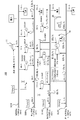
- FIG. 1 is a diagram for explaining a steam processing facility 100 according to an embodiment of the present invention.
- the steam processing facility 100 shown in FIG. 1 may be a steam processing facility used in, for example, an oil refinery plant, a petrochemical plant, a thermal power plant, or the like.
- the steam processing facility 100 includes a plurality of process units 10 (first to n-th process units 10_1 to 10_n), a boiler 11, a high-pressure steam header SHH, an intermediate-pressure steam header SMH, and a low-pressure A steam header SLH and a low-pressure steam compressor 30 are provided.
- the first to n-th process units 10_1 to 10_n are each provided with process equipment (for example, a heat exchanger, a reactor, a heater, a pump, a compressor, etc.) for performing a predetermined production process.
- process equipment for example, a heat exchanger, a reactor, a heater, a pump, a compressor, etc.
- the first process unit 10_1 includes a process facility for generating gasoline from petroleum, and a second process unit (not shown) for generating naphtha from gasoline, for example.
- the n-th process unit 10_n includes a process facility for generating kerosene from petroleum.
- Each process unit 10 includes an air-cooled heat exchanger (air fin cooler) AFC and a kettle type heat exchanger 38.
- the air-cooled heat exchanger AFC cools and liquefies the process fluid generated in the chemical production process. However, in the air-cooled heat exchanger AFC, heat energy is released without being recovered. Therefore, in the present embodiment, at least a part of the process fluid is bypassed before the air-cooled heat exchanger AFC and supplied to the kettle heat exchanger 38.
- the kettle heat exchanger 38 is supplied with cooling water (BFW: Boiler ⁇ ⁇ Feed Water).
- BFW Boiler ⁇ ⁇ Feed Water
- Each process unit 10 is connected to a high pressure steam header SHH, an intermediate pressure steam header SMH, and a low pressure steam header SLH.
- the high-pressure steam header SHH is a header that accommodates high-pressure steam based on, for example, about 4.4 MPaG and about 394 ° C.
- the medium pressure steam header SMH is a header that stores medium pressure steam based on about 1.37 MPaG and about 240 ° C., for example.
- the low-pressure steam header SLH is a header that stores low-pressure steam based on, for example, about 0.15 MPaG and about 128 ° C.
- the high-pressure steam header SHH, the medium-pressure steam header SMH, and the low-pressure steam header SLH are common to the first to n-th process units 10_1 to 10_n.
- a first pressure control valve 13 is provided between the high pressure steam header SHH and the intermediate pressure steam header SMH. By controlling the first pressure control valve 13, the pressures of the high-pressure steam header SHH and the intermediate-pressure steam header SMH can be controlled to predetermined values.
- a second pressure control valve 15 is provided between the intermediate pressure steam header SMH and the low pressure steam header SLH. By controlling the second pressure control valve 15, the pressures of the intermediate pressure steam header SMH and the low pressure steam header SLH can be controlled to predetermined values.
- the boiler 11 generates high-pressure steam (for example, about 4.4 MPaG, about 394 ° C.) using, for example, C heavy oil, off-gas, and the like as fuel, and supplies the high-pressure steam to the high-pressure steam header SHH.
- the boiler 11 may be, for example, an FCC CO boiler.
- the high-pressure steam supplied from the boiler 11 is sent to each process unit 10 via the high-pressure steam header SHH.
- the high pressure steam is supplied from the high pressure steam header SHH to the high pressure steam using device 17 of each process unit 10.
- the high-pressure steam using device 17 performs work using the high-pressure steam, and discharges the steam whose pressure has decreased (medium-pressure steam) to the medium-pressure steam header SMH.
- the medium pressure steam is supplied from the medium pressure steam header SMH to the medium pressure steam using device 19 of each process unit 10.
- the medium pressure steam using device 19 performs work using the medium pressure steam, and discharges the steam whose pressure has decreased (low pressure steam) to the low pressure steam header SLH.
- the low-pressure steam generated in the kettle heat exchanger 38 of each process unit 10 is supplied to the low-pressure steam header SLH in addition to the low-pressure steam discharged from the medium-pressure steam using device of each process unit 10. Is done.
- the low pressure steam is supplied from the low pressure steam header SLH to the low pressure steam use device 21 of each process unit 10.
- the low-pressure steam using device 21 performs work using low-pressure steam.
- the high-pressure steam using device 17, the medium-pressure steam using device 19, and the low-pressure steam using device 21 may be a turbine, a pump, a heat exchanger, or the like.
- the low-pressure steam is used in the low-pressure steam using device 21 of each process unit 10 as described above, or a condensing turbine generator is connected to the low-pressure steam header SLH, and the condensing turbine generator is used.
- low-pressure steam power generation is performed.
- the amount of low-pressure steam generated in the steam treatment facility often greatly exceeds the demand of the existing low-pressure steam use device 21, and a lot of excess low-pressure steam is generated.
- Supplying surplus low-pressure steam to the condensate turbine generator and generating low-pressure steam can increase the efficiency of using low-pressure steam.
- condensate turbine generators are expensive, Economic efficiency decreases. Therefore, in the conventional steam processing equipment, there are many cases where low-pressure steam that has not been used up by the low-pressure steam using device 21 of each process unit 10 is released into the atmosphere, and there is room for improvement from the viewpoint of energy saving.
- the steam processing facility 100 includes the low-pressure steam compression unit 30 between the medium-pressure steam header SMH and the low-pressure steam header SLH.
- the low-pressure steam compression unit 30 includes a compressor 24 that compresses the low-pressure steam from the low-pressure steam header SLH, and an electric motor (motor) 26 that starts and constantly operates the compressor 24. ing.
- the low-pressure steam compression unit 30 boosts the low-pressure steam supplied from the low-pressure steam header SLH to medium-pressure steam of about 1 to 1.5 MPaG (eg, 1.37 MPaG) and supplies the medium-pressure steam header SMH.
- the increased intermediate pressure steam is sent to each process unit 10 via the intermediate pressure steam header SMH, and is used in the intermediate pressure steam use device 19 of each process unit 10.
- the added value of the low-pressure steam that has been released into the atmosphere as a surplus is increased, and the usage destination can be expanded.
- the energy required for boosting the low-pressure steam to the medium-pressure steam (that is, the energy for driving the electric motor 26) is significantly less than the energy necessary for generating the medium-pressure steam using the boiler. Therefore, according to the steam treatment facility 100 according to the present embodiment, at least a part of the medium pressure steam that has been generated by using a conventional boiler is converted into low pressure steam that is generated by heating and evaporating water using a process fluid. By substituting with medium-pressure steam obtained by increasing the pressure, the energy saving effect can be improved.
- the thermal efficiency is as low as about 12%.
- condensate turbine generators that support low-pressure steam are currently manufactured by a small number of manufacturers and are not easily procured.
- the thermal efficiency is 15% or more.
- many low-pressure mixed-air condensate turbine generators are manufactured and are easy to procure. Therefore, as in the present embodiment, by recovering the recovered low-pressure steam to medium-pressure steam, a low-pressure mixed gas condensate turbine generator with high thermal efficiency and easy procurement can be used effectively. It becomes like this.
- low-pressure steam is recovered from the first to n-th process units 10_1 to 10_n.
- the recovered low-pressure steam includes excess low-pressure steam that has not been used in the low-pressure steam use device 21 of each process unit 10 and low-pressure steam generated in the kettle heat exchanger 38 of each process unit 10.
- the recovered low-pressure steam is sent to the low-pressure steam compression unit 30 via the low-pressure steam header SLH, and the pressure is increased to medium pressure steam.
- the pressurized intermediate pressure steam is sent to each process unit 10 via the intermediate pressure steam header SMH, and used by the intermediate pressure steam using device 19.
- the first process unit 10_1 has high use efficiency of low pressure steam
- the nth process unit 10_n has low use efficiency of low pressure steam.
- a difference in utilization efficiency of the low-pressure steam is caused for each process unit 10 such as low. Therefore, in this case, there is a possibility that a sufficient energy saving effect of the steam treatment facility cannot be achieved.
- the low-pressure steam recovered from each process unit 10 is collectively boosted to medium-pressure steam by the low-pressure steam compression unit 30, and the boosted medium-pressure steam is supplied to each process unit 10. Since it is sent and used, a situation in which the use efficiency of low-pressure steam is different for each process unit 10 is avoided, and a sufficient energy saving effect can be achieved as the entire steam processing facility 100.
- the recovered low-pressure steam is The present invention can be used not only for the medium pressure steam using device 19 provided in a specific process unit but also for the medium pressure steam using device 19 provided in another process unit.
- the low-pressure steam that has been used for a limited time and has not been used much can be effectively used as energy, and energy saving can be achieved.
- FIG. 2 is a view for explaining a steam processing facility according to another embodiment of the present invention.
- the reference pressure (for example, 1.37 MPaG) of the existing medium pressure steam header SMH is higher than the pressure (for example, 1.05 MPaG or 0.75 MPaG) that can be increased by the low pressure steam compression unit 30, as shown in FIG.
- a semi-intermediate pressure steam header SubSMH that accommodates steam (referred to as "semi-medium pressure steam") having a pressure (for example, 1.05 MPaG or 0.75 MPaG) between the steam and the low-pressure steam is newly provided.
- This semi-intermediate pressure steam header SubSMH is connected to each process unit 10.
- the lower limit pressure of the steam used in equipment such as the back pressure turbine 23 of each process unit that uses the intermediate pressure steam is checked. If the lower limit pressure is high, the sub intermediate pressure steam of the sub intermediate pressure steam header SubSMH is used. Modify the equipment to fit.
- the quasi-medium pressure steam boosted by the low-pressure steam compression unit 30 is supplied to each process unit via the quasi-medium pressure steam header SubSMH and used by the modified back pressure turbine 23 '.
- the low pressure steam compression unit 30 compresses the low pressure steam and does not reach the medium pressure steam pressure of the existing plant as in the present embodiment, a semi-medium pressure steam dedicated header is installed and the existing back pressure is set.
- the turbine 23 By modifying and applying the turbine 23, the amount of steam generated in the plant by the boiler 11 can be greatly reduced, and the energy saving effect can be improved.
- FIG. 3 is a view for explaining a steam treatment facility according to still another embodiment of the present invention.
- the steam generated in the kettle heat exchanger 38 of each process unit 10 may not reach the reference pressure (for example, 0.15 MPaG) of the existing low-pressure steam header SLH (steam lower in pressure than such low-pressure steam ( For example, 0.1 MPaG) is referred to as “sub-low pressure steam”).
- SLH steam lower in pressure than such low-pressure steam (for example, 0.1 MPaG) is referred to as “sub-low pressure steam”.
- a semi-low pressure steam header SubSLH that accommodates semi-low pressure steam is newly installed.
- the semi-low pressure steam recovered from each process unit is boosted to medium pressure steam by the low pressure steam compressor 30 and supplied to the medium pressure steam header SMH.
- a semi-low pressure steam header SubSLH is installed, and the semi-low pressure steam is boosted to medium pressure steam and used in each process unit.
- the low-pressure steam compression unit 30 may be used to raise the semi-low-pressure steam of the semi-low-pressure steam header SubSLH to quasi-medium-pressure steam and supply it to the quasi-medium-pressure steam header SubSMH.
- FIG. 4 is a diagram for explaining a modification of the low-pressure steam compression unit.
- the compressor 24 is activated and always operated by an electric motor 26.
- a low-pressure steam compressor 40 shown in FIG. 4 includes a compressor 24 that compresses low-pressure steam from the low-pressure steam header SLH, and a steam turbine 41 that starts and constantly operates the compressor 24 using the low-pressure steam from the low-pressure steam header SLH. It is comprised including.
- an electric motor is not necessary, and further effective use of low-pressure steam can be achieved.
- FIG. 5 is a diagram for explaining another modified example of the low-pressure steam compression unit.
- the low-pressure steam compressor 50 shown in FIG. 5 includes a compressor 24 that compresses low-pressure steam from the low-pressure steam header SLH, a steam turbine 41 that starts the compressor 24 using low-pressure steam from the low-pressure steam header SLH, After the compressor 24 is started by the turbine 41, an electric motor 42 that always operates the compressor 24 instead of the steam turbine 41 is configured.
- FIG. 6 is a diagram for explaining still another modified example of the low-pressure steam compression unit.
- the low-pressure steam compression unit 60 shown in FIG. 6 compresses using the compressor 24 that compresses the low-pressure steam from the low-pressure steam header SLH, and the low-pressure steam from the low-pressure steam header SLH and the medium-pressure steam from the medium-pressure steam header SMH. And an air-mixing turbine 61 that starts and constantly operates the machine 24.
- an electric motor is not required, and the degree of freedom of steam distribution is dramatically improved even when the amount of low-pressure steam and medium-pressure steam collected through plant operation varies. The energy saving effect in the steam treatment facility 100 can be maximized.
- FIG. 7 is a diagram for explaining still another modified example of the low-pressure steam compression unit.
- the low-pressure steam compressor 70 shown in FIG. 7 compresses using the compressor 24 that compresses the low-pressure steam from the low-pressure steam header SLH, and the low-pressure steam from the low-pressure steam header SLH and the medium-pressure steam from the medium-pressure steam header SMH.
- An air-mixing turbine 61 that drives the compressor 24, and a motor generator 62 that generates induction using the surplus power when surplus power exceeding the power required to drive the compressor 24 is generated in the air-mixing turbine 61.
- the compressor 24 is driven using power that is a combination of the power from the mixed gas turbine 61 and the power from the motor generator 62.
- the motor generator 62 can function as an electric motor or a generator in accordance with fluctuations in the amount of low-pressure steam generated and demand fluctuations in medium-pressure steam. The energy saving effect in the facility 100 can be further improved.
- FIG. 8 is a diagram for explaining still another modified example of the low-pressure steam compression unit.
- a low-pressure steam compression unit 80 shown in FIG. 8 is a modification of the low-pressure steam compression unit 50 shown in FIG. 5, and includes a compressor 24 that compresses low-pressure steam from the low-pressure steam header SLH and low-pressure steam from the low-pressure steam header SLH.
- a steam turbine 41 that drives the compressor 24 using steam and a condenser 43 connected to the steam turbine 41 are provided.
- the steam turbine 41 is driven by low-pressure steam, so that a vacuum state is generated from the steam turbine 41 to the condenser 43.
- the compressor 24 is brought into a vacuum state using the vacuum generated in the steam turbine 41 when the compressor 24 is started.
- the mixed gas turbine 61 described with reference to FIG. 6 may be used instead of the steam turbine 41.
- the compressor 24 may be brought into a vacuum state using a vacuum generated by a vacuum generator 47 connected to the condenser 43.
- a vacuum generator 47 a vacuum pump or a steam ejector can be used.
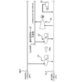
- FIG. 9 shows a steam treatment facility according to the first embodiment of the present invention.
- the steam processing facility 100 according to the first embodiment employs a low-pressure steam compression unit 30 that includes the compressor and the electric motor described in FIG.
- second low pressure steam slightly higher than the 0.15 MPaG low pressure steam (referred to as “first low pressure steam”) described in the above embodiment.
- first low pressure steam 1.05 MPaG quasi-intermediate pressure steam that is slightly lower than 1.37 MPaG medium pressure steam is set. Therefore, the steam processing facility 100 according to the first embodiment accommodates the high-pressure steam header SHH that accommodates high-pressure steam, the medium-pressure steam header SMH that accommodates medium-pressure steam, and the semi-medium-pressure steam in descending order of the accommodated steam pressure.
- a sub-medium pressure steam header SubSMH, a second low-pressure steam header SLH2 that accommodates the second low-pressure steam, and a first low-pressure steam header SLH1 that accommodates the first low-pressure steam are provided.
- the first low-pressure steam header SLH1 corresponds to the low-pressure steam header SLH described in FIG.
- 100 t / h of the first low-pressure steam is recovered by the kettle heat exchanger 38 of each process unit.
- the letdown from the intermediate pressure steam header SMH to the second low pressure steam header SLH2 is set to 0 t / h, and the letdown from the second low pressure steam header SLH2 to the first low pressure steam header SLH1 is set according to the header balance.
- the first low-pressure steam 56 t / h is increased to 1.05 MPaG using the low-pressure steam compression unit 30 so that the purchased steam becomes 0 t / h.
- 33 of the 60 pumps driven by medium pressure steam have been modified to 1.05 MPaG specifications and connected to the sub-medium pressure steam header SubSMH.
- the low-pressure steam 38.8 t / h that could not be boosted by the low-pressure steam compressor 30 is supplied to the radial turbine condensate generator 45 and used for power generation.
- FIG. 10 shows a steam treatment facility according to the second embodiment of the present invention.
- the steam processing facility 100 according to the second embodiment also employs the low-pressure steam compression unit 30 that includes the compressor and the electric motor described in FIG.
- the second embodiment 61.2 t / h of the first low-pressure steam is recovered so that the purchased steam becomes 0 t / h.
- the letdown from the intermediate pressure steam header SMH to the second low pressure steam header SLH2 is set to 0 t / h, and the letdown from the second low pressure steam header SLH2 to the first low pressure steam header SLH1 is set according to the header balance.
- the first low-pressure steam 56 t / h is increased to 1.05 MPaG so that the purchased steam becomes 0 t / h.
- 33 of the 60 pumps driven by medium pressure steam are modified to 1.05 MPaG specifications and connected to the sub-medium pressure steam header SubSMH.
- the low-pressure steam compression unit 30 uses up the recovered low-pressure steam, and no excessive low-pressure steam is generated.
- FIG. 11 shows a steam treatment facility according to the third embodiment of the present invention.
- the steam treatment facility 100 according to the third embodiment employs a low-pressure steam compressor 60 (mixed condensate turbine compressor) composed of the compressor and mixed gas turbine described in FIG.
- a low-pressure steam compressor 60 mixed condensate turbine compressor
- 100 t / h of the first low-pressure steam is recovered by the kettle heat exchanger 38 of each process unit.
- the letdown from the intermediate pressure steam header SMH to the second low pressure steam header SLH2 is set to 0 t / h, and the letdown from the second low pressure steam header SLH2 to the first low pressure steam header SLH1 is set according to the header balance.
- the first low-pressure steam 57 t / h is increased to 1.05 MPaG using the low-pressure steam compression unit 60 so that the purchased steam is minimized.
- the introduction amount of 1.05 MPaG quasi-medium pressure steam to the mixed gas turbine of the low-pressure steam compression unit 60 is set to 1 ⁇ 4 of the introduction amount of the first low-pressure steam of 0.15 MPaG.
- 27 of the 60 pumps driven by medium pressure steam are modified to 1.05 MPaG specifications and connected to the sub-medium pressure steam header SubSMH.
- the low-pressure steam compression unit 30 uses up the recovered low-pressure steam, and no excessive low-pressure steam is generated.
- FIG. 12 shows a steam processing facility according to the fourth embodiment of the present invention.
- the steam processing facility 100 according to the fourth embodiment employs a low-pressure steam compression unit 70 configured by the compressor, the mixed gas turbine, and the motor generator 62 described in FIG.
- 130 t / h of the first low-pressure steam is recovered by the kettle heat exchanger 38 of each process unit.
- the letdown from the intermediate pressure steam header SMH to the second low pressure steam header SLH2 is set to 0 t / h, and the letdown from the second low pressure steam header SLH2 to the first low pressure steam header SLH1 is set according to the header balance.
- the first low-pressure steam 67 t / h is increased to 1.05 MPaG using the low-pressure steam compression unit 60 so that the purchased steam is minimized.
- 27 pumps out of 60 pumps driven by medium pressure steam are remodeled to 1.05 MPaG specifications and connected to the sub-medium pressure steam header SubSMH.
- the low-pressure steam compression unit 30 uses up the recovered low-pressure steam, and no excessive low-pressure steam is generated.
- FIG. 13 shows the merits of the steam treatment facility according to the first to third embodiments.
- the steam processing facility 100 according to the first to third embodiments has an economic effect that is three times or more as compared with a steam processing facility that simply uses conventional low-pressure steam for turbine power generation. In this way, by substituting at least a part of the intermediate pressure steam that has been purchased in the past with the intermediate pressure steam obtained by increasing the pressure of the low pressure steam generated by heating and evaporating water using the process fluid. The plant can be operated economically.
- the low pressure steam is generated from the cooling water using the kettle heat exchanger 38 in each process unit 10, and the low pressure steam is increased to the medium pressure steam.
- the cooling water used in each process unit 10 is recovered, and the low-temperature steam is generated by raising the temperature of the recovered cooling water using a heat pump. It is good also as a structure which pressure
- the return cooling water after cooling has been simply used for re-cooling circulation by heat release in a cooling tower or the like, but by adopting the configuration as described above, heat release is greatly reduced, and the added value is high. Since it can be converted into steam, the energy saving effect of the steam treatment facility can be greatly improved.
- the present invention can be used for plants such as an oil refinery plant, a petrochemical plant, and a thermal power plant.
Landscapes
- Engineering & Computer Science (AREA)
- Chemical & Material Sciences (AREA)
- Combustion & Propulsion (AREA)
- Mechanical Engineering (AREA)
- General Engineering & Computer Science (AREA)
- Engine Equipment That Uses Special Cycles (AREA)
- Control Of Turbines (AREA)
- Jet Pumps And Other Pumps (AREA)
Abstract
蒸気処理設備(100)は、中圧蒸気を収容する中圧蒸気ヘッダ(SMH)と、低圧蒸気を収容する低圧蒸気ヘッダ(SLH)と、中圧蒸気ヘッダ(SMH)および低圧蒸気ヘッダ(SLH)が接続された複数のプロセスユニット(10)と、低圧蒸気ヘッダ(SLH)から供給される低圧蒸気を昇圧して中圧蒸気とし、中圧蒸気ヘッダ(SMH)に供給する低圧蒸気圧縮部(30)とを備える。各プロセスユニット(10)で発生した低圧蒸気は、低圧蒸気ヘッダ(SLH)に回収される。低圧蒸気ヘッダ(SLH)に回収された低圧蒸気は、低圧蒸気圧縮部(30)により中圧蒸気に昇圧された後、中圧蒸気ヘッダ(SMH)を介して各プロセスユニット(10)に供給される。
Description
本発明は、プラントにおいて蒸気を処理する蒸気処理設備および蒸気処理方法に関する。
従来より、例えば石油プラントなどのプラントにおいて、ボイラーによって生成した蒸気を高圧蒸気(例えば4.0~12.0MPaG)、中圧蒸気(例えば1.0~2.0MPaG)、低圧蒸気(例えば0.01~0.6MPaG)などに分け、それらの蒸気を蒸気タービンなどの蒸気使用装置や各種生産プロセスに供給する蒸気処理設備が知られている(例えば、特許文献1参照)。
このような蒸気処理設備においては、蒸気タービンなどの蒸気使用装置から大量の低圧蒸気が発生する。従来の蒸気処理設備では、このような低圧蒸気を回収し、低圧蒸気発電または既存の低圧蒸気使用プロセスに利用するのが殆どであった。しかしながら、蒸気処理設備で発生する低圧蒸気量は、既存の低圧蒸気使用プロセスの需要量を大きく超える場合が多く、回収された低圧蒸気が十分に利用されているとは言い難い。また、低圧蒸気を用いた復水タービン発電は設備費がかさむため、経済性がかなり低下する可能性がある。このように、従来の蒸気処理設備では、低圧蒸気は需要先と利用効果が限定されているため、回収余地があるにもかかわらず十分に活用されておらず、省エネルギーの観点から改善の余地がある。
本発明は、こうした状況を鑑みてなされたものであり、その目的は、省エネルギー効果を向上できる蒸気処理設備および蒸気処理方法を提供することにある。
上記課題を解決するために、本発明のある態様の蒸気処理設備は、中圧蒸気を収容する中圧蒸気ヘッダと、低圧蒸気を収容する低圧蒸気ヘッダと、中圧蒸気ヘッダおよび低圧蒸気ヘッダが接続された複数のプロセスユニットと、低圧蒸気ヘッダから供給される低圧蒸気を昇圧して中圧蒸気とし、中圧蒸気ヘッダに供給する低圧蒸気圧縮部とを備える。各プロセスユニットで発生した低圧蒸気は、低圧蒸気ヘッダに回収される。低圧蒸気ヘッダに回収された低圧蒸気は、低圧蒸気圧縮部により中圧蒸気に昇圧された後、中圧蒸気ヘッダを介して各プロセスユニットに供給される。
低圧蒸気圧縮部は、低圧蒸気ヘッダからの低圧蒸気を圧縮する圧縮機と、低圧蒸気ヘッダからの低圧蒸気を用いて圧縮機を起動させる蒸気タービンと、蒸気タービンにより圧縮機が起動された後に、蒸気タービンに代えて圧縮機を常時運転させる電動機とを含んでもよい。
低圧蒸気圧縮部は、低圧蒸気ヘッダからの低圧蒸気を圧縮する圧縮機と、低圧蒸気ヘッダからの低圧蒸気を用いて圧縮機を駆動する蒸気タービンとを含んでもよい。
低圧蒸気圧縮部は、低圧蒸気ヘッダからの低圧蒸気を圧縮する圧縮機と、低圧蒸気ヘッダからの低圧蒸気および中圧蒸気ヘッダからの中圧蒸気を用いて圧縮機を駆動する混気タービンとを含んでもよい。
低圧蒸気圧縮部は、低圧蒸気ヘッダからの低圧蒸気を圧縮する圧縮機と、低圧蒸気ヘッダからの低圧蒸気および中圧蒸気ヘッダからの中圧蒸気を用いて圧縮機を駆動する混気タービンと、圧縮機の駆動に必要な動力を超える余剰動力が混気タービンで発生した場合に該余剰動力を用いて誘導発電する電動発電機とを含んでもよい。
混気タービンで余剰動力が発生しない場合、混気タービンからの動力と電動発電機からの動力とを合わせた動力を用いて圧縮機が駆動されてもよい。
低圧蒸気圧縮部は、低圧蒸気ヘッダからの低圧蒸気を圧縮する圧縮機と、低圧蒸気ヘッダからの低圧蒸気を用いて圧縮機を駆動する蒸気タービンまたは低圧蒸気ヘッダからの低圧蒸気および中圧蒸気ヘッダからの中圧蒸気を用いて圧縮機を駆動する混気タービンと、を備えてもよい。蒸気タービンまたは混気タービンで生じた真空を用いて、起動の際に圧縮機が真空状態とされてもよい。
各プロセスユニットは、プロセス流体を用いて水を加熱蒸発させて低圧蒸気を発生させる熱交換器を備えてもよい。
各プロセスユニットで使用した冷却水を回収する冷却水回収手段と、回収された冷却水を昇温して低圧蒸気を発生させるヒートポンプとを更に備えてもよい。
本発明の別の態様もまた、蒸気処理設備である。この蒸気処理設備は、中圧蒸気を収容する中圧蒸気ヘッダと、低圧蒸気を収容する低圧蒸気ヘッダと、中圧蒸気と低圧蒸気の間の準中圧蒸気を収容する準中圧蒸気ヘッダと、中圧蒸気ヘッダ、低圧蒸気ヘッダおよび準中圧蒸気ヘッダが接続された複数のプロセスユニットと、低圧蒸気ヘッダから供給される低圧蒸気を昇圧して準中圧蒸気とし、準中圧蒸気ヘッダに供給する低圧蒸気圧縮部とを備える。各プロセスユニットで発生した低圧蒸気は、低圧蒸気ヘッダに回収される。低圧蒸気ヘッダに回収された低圧蒸気は、低圧蒸気圧縮部により準中圧蒸気に昇圧された後、準中圧蒸気ヘッダを介して各プロセスユニットに供給される。
本発明の更に別の態様もまた、蒸気処理設備である。この蒸気処理設備は、中圧蒸気を収容する中圧蒸気ヘッダと、低圧蒸気を収容する低圧蒸気ヘッダと、低圧蒸気よりも低い準低圧蒸気を収容する準低圧蒸気ヘッダと、中圧蒸気ヘッダ、低圧蒸気ヘッダおよび準低圧蒸気ヘッダが接続された複数のプロセスユニットと、準低圧蒸気ヘッダから供給される準低圧蒸気を昇圧して中圧蒸気とし、中圧蒸気ヘッダに供給する低圧蒸気圧縮部とを備える。各プロセスユニットで発生した準低圧蒸気は、準低圧蒸気ヘッダに回収される。準低圧蒸気ヘッダに回収された準低圧蒸気は、低圧蒸気圧縮部により中圧蒸気に昇圧された後、中圧蒸気ヘッダを介して各プロセスユニットに供給される。
本発明の更に別の態様は、蒸気処理方法である。この方法は、複数のプロセスユニットから低圧蒸気を回収するステップと、回収された低圧蒸気を昇圧して中圧蒸気とするステップと、昇圧された中圧蒸気を各プロセスユニットに供給するステップとを備える。
なお、以上の構成要素の任意の組合せ、本発明の表現を方法、装置、システム、記録媒体、コンピュータプログラムなどの間で変換したものもまた、本発明の態様として有効である。
本発明によれば、省エネルギー効果を向上できる蒸気処理設備および蒸気処理方法を提供できる。
図1は、本発明の実施形態に係る蒸気処理設備100を説明するための図である。図1に示す蒸気処理設備100は、例えば石油精製プラント、石油化学プラント、火力発電プラントなどで用いられる蒸気処理設備であってよい。
図1に示すように、蒸気処理設備100は、複数のプロセスユニット10(第1~第nプロセスユニット10_1~10_n)と、ボイラー11と、高圧蒸気ヘッダSHHと、中圧蒸気ヘッダSMHと、低圧蒸気ヘッダSLHと、低圧蒸気圧縮部30とを備える。
第1~第nプロセスユニット10_1~10_nは、それぞれ所定の生産プロセスを行うためのプロセス設備(例えば、熱交換器、反応器、加熱器、ポンプ、コンプレッサなど)を備えている。例えば蒸気処理設備100が石油プラントであれば、例えば第1プロセスユニット10_1は石油からガソリンを生成するためのプロセス設備を備え、例えば第2プロセスユニット(図示せず)はガソリンからナフサを生成するためのプロセス設備を備え、例えば第nプロセスユニット10_nは石油から灯油を生成するためのプロセス設備を備える。
各プロセスユニット10は、空冷式熱交換器(エアフィンクーラ)AFCと、ケトル型熱交換器38とを備える。空冷式熱交換器AFCは、化学物質の生成プロセスで生じたプロセス流体を冷却して液化する。しかしながら、空冷式熱交換器AFCでは熱エネルギーが回収されずに放出されてしまう。そこで、本実施形態では、プロセス流体の少なくとも一部を空冷式熱交換器AFCの手前でバイパスさせ、ケトル型熱交換器38に供給する。ケトル型熱交換器38には、冷却水(BFW:Boiler Feed Water)が供給される。ケトル型熱交換器38は、プロセス流体との熱交換によりこのBFWを加熱蒸発し、0.15MPaG、128℃の低圧蒸気を発生させる。
各プロセスユニット10には、高圧蒸気ヘッダSHH、中圧蒸気ヘッダSMHおよび低圧蒸気ヘッダSLHが接続されている。高圧蒸気ヘッダSHHは、例えば約4.4MPaG、約394℃を基準とする高圧蒸気を収容するヘッダである。また、中圧蒸気ヘッダSMHは、例えば約1.37MPaG、約240℃を基準とする中圧蒸気を収容するヘッダである。また、低圧蒸気ヘッダSLHは、例えば約0.15MPaG、約128℃を基準とする低圧蒸気を収容するヘッダである。高圧蒸気ヘッダSHH、中圧蒸気ヘッダSMHおよび低圧蒸気ヘッダSLHは、第1~第nプロセスユニット10_1~10_nに対して共通である。
高圧蒸気ヘッダSHHと中圧蒸気ヘッダSMHとの間には、第1圧力制御弁13が設けられている。この第1圧力制御弁13を制御することにより、高圧蒸気ヘッダSHHおよび中圧蒸気ヘッダSMHの圧力を所定の値に制御することができる。
また、中圧蒸気ヘッダSMHと低圧蒸気ヘッダSLHとの間には、第2圧力制御弁15が設けられている。この第2圧力制御弁15を制御することにより、中圧蒸気ヘッダSMHおよび低圧蒸気ヘッダSLHの圧力を所定の値に制御することができる。
ボイラー11は、例えばC重油、オフガスなどを燃料として高圧蒸気(例えば約4.4MPaG、約394℃)を発生し、該高圧蒸気を高圧蒸気ヘッダSHHに供給する。ボイラー11は、例えばFCC COボイラーであってよい。
ボイラー11から供給された高圧蒸気は、高圧蒸気ヘッダSHHを介して各プロセスユニット10に送られる。高圧蒸気は、高圧蒸気ヘッダSHHから各プロセスユニット10の高圧蒸気使用装置17に供給される。高圧蒸気使用装置17は、高圧蒸気を用いて仕事を行い、圧力が低下した蒸気(中圧蒸気)を中圧蒸気ヘッダSMHに排出する。
また、中圧蒸気は、中圧蒸気ヘッダSMHから各プロセスユニット10の中圧蒸気使用装置19に供給される。中圧蒸気使用装置19は、中圧蒸気を用いて仕事を行い、圧力が低下した蒸気(低圧蒸気)を低圧蒸気ヘッダSLHに排出する。
本実施形態において、低圧蒸気ヘッダSLHには、各プロセスユニット10の中圧蒸気使用装置から排出される低圧蒸気に加えて、各プロセスユニット10のケトル型熱交換器38で発生した低圧蒸気が供給される。
低圧蒸気は、低圧蒸気ヘッダSLHから各プロセスユニット10の低圧蒸気使用装置21に供給される。低圧蒸気使用装置21は、低圧蒸気を用いて仕事を行う。高圧蒸気使用装置17、中圧蒸気使用装置19及び低圧蒸気使用装置21は、タービン、ポンプ、熱交換器等であってよい。
従来の蒸気処理設備では、低圧蒸気は上記のように各プロセスユニット10の低圧蒸気使用装置21で使用するか、低圧蒸気ヘッダSLHに復水タービン発電機を接続し、復水タービン発電機を用いて低圧蒸気発電を行うのが一般的である。しかしながら、蒸気処理設備で発生する低圧蒸気量は、既存の低圧蒸気使用装置21の需要量を大きく超える場合が多く、多くの余剰の低圧蒸気が発生する。余剰となった低圧蒸気を復水タービン発電機に供給して低圧蒸気発電を行えば低圧蒸気の利用効率を高めることができるが、復水タービン発電機は高コストであるため、蒸気処理設備の経済性が低下する。従って、従来の蒸気処理設備では、各プロセスユニット10の低圧蒸気使用装置21で使い切れなかった低圧蒸気は大気中に放出されているケースが多く、省エネルギーの観点から改善の余地がある。
そこで、本実施形態に係る蒸気処理設備100は、中圧蒸気ヘッダSMHと低圧蒸気ヘッダSLHとの間に低圧蒸気圧縮部30を備える。本実施形態において、低圧蒸気圧縮部30は、低圧蒸気ヘッダSLHからの低圧蒸気を圧縮する圧縮機24と、圧縮機24を起動および常時運転させるための電動機(モータ)26とを含んで構成されている。
低圧蒸気圧縮部30は、低圧蒸気ヘッダSLHから供給される低圧蒸気を1~1.5MPaG程度(例えば1.37MPaG)の中圧蒸気に昇圧し、中圧蒸気ヘッダSMHに供給する。この昇圧された中圧蒸気は、中圧蒸気ヘッダSMHを介して各プロセスユニット10に送られ、各プロセスユニット10の中圧蒸気使用装置19で利用される。
本実施形態のように、回収した低圧蒸気を昇圧して中圧蒸気とすることで、従来余剰となって大気放出されていた低圧蒸気の付加価値が高まり、利用先を拡大することができる。低圧蒸気を中圧蒸気に昇圧するのに必要なエネルギー(すなわち、電動機26を駆動するエネルギー)は、ボイラーを用いて中圧蒸気を発生するのに必要なエネルギーに較べて大幅に少ない。従って、本実施形態に係る蒸気処理設備100によれば、従来ボイラを用いて発生させていた中圧蒸気の少なくとも一部を、プロセス流体を用いて水を加熱蒸発させて発生させた低圧蒸気を昇圧することにより得られた中圧蒸気で代替することにより、省エネルギー効果を向上できる。
蒸気を発電に利用する場合について考えると、低圧蒸気をそのまま復水タービン発電機に供給して低圧蒸気発電を行う場合、熱効率は12%程度と極めて低い。また、低圧蒸気に対応した復水タービン発電機は、現状では製造している製造業者が少なく、調達が容易ではない。一方、中圧蒸気を主蒸気とする低圧混気復水タービン発電機を用いて発電を行う場合、熱効率は15%以上となる。また、低圧混気復水タービン発電機は製造している製造業者が多く、調達が容易である。従って、本実施形態のように、回収した低圧蒸気を昇圧して中圧蒸気とすることで、熱効率が高く、且つ調達が容易な低圧混気復水タービン発電機を効果的に用いることができるようになる。
本実施形態に係る蒸気処理設備100では、第1~第nプロセスユニット10_1~10_nから低圧蒸気が回収される。回収される低圧蒸気は、各プロセスユニット10の低圧蒸気使用装置21で使用されなかった余剰の低圧蒸気と、各プロセスユニット10のケトル型熱交換器38で発生した低圧蒸気とを含む。回収された低圧蒸気は、低圧蒸気ヘッダSLHを介して低圧蒸気圧縮部30に送られ、中圧蒸気に昇圧される。そして、この昇圧された中圧蒸気は、中圧蒸気ヘッダSMHを介して各プロセスユニット10に送られ、中圧蒸気使用装置19で利用される。
例えば、プロセスユニット10ごとに低圧蒸気を中圧蒸気に昇圧して利用している場合、例えば第1プロセスユニット10_1は低圧蒸気の利用効率が高いが、第nプロセスユニット10_nは低圧蒸気の利用効率が低いといったように、プロセスユニット10ごとに低圧蒸気の利用効率に差が生じる可能性がある。従って、この場合、蒸気処理設備の十分な省エネルギー効果を達成できない可能性がある。
一方、本実施形態に係るプロセスユニット10の場合、各プロセスユニット10から回収した低圧蒸気を低圧蒸気圧縮部30で一括して中圧蒸気に昇圧し、昇圧した中圧蒸気を各プロセスユニット10に送って利用しているので、プロセスユニット10ごとに低圧蒸気の利用効率に差が生じるといった事態が回避され、蒸気処理設備100全体として十分な省エネルギー効果を達成できる。このように複数のプロセスユニット10_1~10_nから回収された低圧蒸気を昇圧して、異なるプロセスユニットに設けられた複数の中圧蒸気使用装置19に用いることができるため、回収された低圧蒸気を、特定のプロセスユニットに設けられた中圧蒸気使用装置19のみならず、他のプロセスユニットに設けられた中圧蒸気使用装置19にも利用することができる。これにより、従来、用途が限定され、あまり利用されていなかった低圧蒸気をエネルギーとして有効に利用することができ、省エネルギーが可能になる。また、購入した蒸気やボイラーにより発生させた蒸気を用いることなく中圧蒸気使用装置19に仕事をさせることも可能になり、中圧蒸気使用装置19による仕事を経済的に行うことができる。
図2は、本発明の別の実施形態に係る蒸気処理設備を説明するための図である。既設の中圧蒸気ヘッダSMHの基準圧力(例えば1.37MPaG)が低圧蒸気圧縮部30で昇圧可能な圧力(例えば1.05MPaGまたは0.75MPaG)より高い場合、図2に示すように、中圧蒸気と低圧蒸気の間の圧力(例えば1.05MPaGまたは0.75MPaG)の蒸気(「準中圧蒸気」と呼ぶ)を収容する準中圧蒸気ヘッダSubSMHを新設する。この準中圧蒸気ヘッダSubSMHは、各プロセスユニット10に接続される。そして、中圧蒸気を利用している各プロセスユニットの背圧タービン23などの機器の使用蒸気の下限圧力をチェックし、下限圧力が高い場合は、準中圧蒸気ヘッダSubSMHの準中圧蒸気に適合するよう機器を改造する。低圧蒸気圧縮部30で昇圧された準中圧蒸気は、準中圧蒸気ヘッダSubSMHを介して各プロセスユニットに供給され、改造された背圧タービン23’により利用される。
本実施形態のように、低圧蒸気圧縮部30で低圧蒸気を圧縮しても既存のプラントの中圧蒸気圧に達しない場合には、準中圧蒸気専用のヘッダを設置し、既存の背圧タービン23を改造して適用することで、ボイラー11によるプラントの蒸気発生量を大幅に低減でき、省エネルギー効果を向上できる。
図3は、本発明の更に別の実施形態に係る蒸気処理設備を説明するための図である。各プロセスユニット10のケトル型熱交換器38で発生した蒸気は、既設の低圧蒸気ヘッダSLHの基準圧力(例えば0.15MPaG)に達しない場合がある(そのような低圧蒸気よりも低圧の蒸気(例えば0.1MPaG)を「準低圧蒸気」と呼ぶ)。このような場合、図3に示すように、準低圧蒸気を収容する準低圧蒸気ヘッダSubSLHを新設する。そして、各プロセスユニットから回収した準低圧蒸気を低圧蒸気圧縮部30により中圧蒸気に昇圧し、中圧蒸気ヘッダSMHに供給する。
本実施形態のように、各プロセスユニットから回収した蒸気が低圧蒸気圧に達しない場合には、準低圧蒸気ヘッダSubSLHを設置し、準低圧蒸気を中圧蒸気に昇圧して各プロセスユニットで利用することで、ボイラー11によるプラントの蒸気発生量を大幅に低減でき、省エネルギー効果を向上できる。なお、低圧蒸気圧縮部30を用いて準低圧蒸気ヘッダSubSLHの準低圧蒸気を準中圧蒸気に昇圧し、準中圧蒸気ヘッダSubSMHに供給してもよい。
図4は、低圧蒸気圧縮部の変形例を説明するための図である。図1に示す低圧蒸気圧縮部30では、圧縮機24は電動機26により起動および常時運転されている。図4に示す低圧蒸気圧縮部40は、低圧蒸気ヘッダSLHからの低圧蒸気を圧縮する圧縮機24と、低圧蒸気ヘッダSLHからの低圧蒸気を用いて圧縮機24を起動および常時運転させる蒸気タービン41とを含んで構成されている。本変形例に係る低圧蒸気圧縮部40によれば、電動機が不要となるとともに、低圧蒸気の更なる有効利用を図ることができる。
図5は、低圧蒸気圧縮部の別の変形例を説明するための図である。図5に示す低圧蒸気圧縮部50は、低圧蒸気ヘッダSLHからの低圧蒸気を圧縮する圧縮機24と、低圧蒸気ヘッダSLHからの低圧蒸気を用いて圧縮機24を起動させる蒸気タービン41と、蒸気タービン41により圧縮機24が起動された後に、蒸気タービン41に代えて圧縮機24を常時運転させる電動機42とを含んで構成されている。
圧縮機を駆動するための電動機として大型のものを導入しようとした場合、通常はプラントの既存受配電設備の増強が必要となる。これは、圧縮機24の起動時に、受配電設備に大きな電気負荷がかかるためである。図5に示す変形例のように、蒸気タービン41により圧縮機24を定格回転数以上まで昇速してから、電動機42の電源を投入することにより、電動機42に流れる大きな起動電流を瞬時に終了させることができる。従って、図5に示す変形例によれば、既存受配電設備の強化を最小限としつつ、電動機42の大型化が可能となる。言い換えると、大型の電動機42の導入に起因する既存受配電設備の抜本的改造を回避できる。
図6は、低圧蒸気圧縮部の更に別の変形例を説明するための図である。図6に示す低圧蒸気圧縮部60は、低圧蒸気ヘッダSLHからの低圧蒸気を圧縮する圧縮機24と、低圧蒸気ヘッダSLHからの低圧蒸気および中圧蒸気ヘッダSMHからの中圧蒸気を用いて圧縮機24を起動および常時運転させる混気タービン61とを含んで構成されている。本変形例に係る低圧蒸気圧縮部60によれば、電動機が不要となるとともに、プラントの運転により回収した低圧蒸気および中圧蒸気の使用量が変動する場合でも蒸気の振り分けの自由度が飛躍的に増加し、蒸気処理設備100における省エネルギー効果を最大化できる。
図7は、低圧蒸気圧縮部の更に別の変形例を説明するための図である。図7に示す低圧蒸気圧縮部70は、低圧蒸気ヘッダSLHからの低圧蒸気を圧縮する圧縮機24と、低圧蒸気ヘッダSLHからの低圧蒸気および中圧蒸気ヘッダSMHからの中圧蒸気を用いて圧縮機24を駆動する混気タービン61と、圧縮機24の駆動に必要な動力を超える余剰動力が混気タービン61で発生した場合に該余剰動力を用いて誘導発電する電動発電機62とを含んで構成されている。低圧蒸気圧縮部70において、混気タービン61で余剰動力が発生しない場合、混気タービン61からの動力と電動発電機62からの動力とを合わせた動力を用いて、圧縮機24が駆動される。本変形例に係る低圧蒸気圧縮部70によれば、低圧蒸気の発生量の変動や中圧蒸気の需要変動に応じて電動発電機62を電動機または発電機として機能させることができるので、蒸気処理設備100における省エネルギー効果をより一層向上できる。
図8は、低圧蒸気圧縮部の更に別の変形例を説明するための図である。図8に示す低圧蒸気圧縮部80は、図5に示す低圧蒸気圧縮部50を変形したものであり、低圧蒸気ヘッダSLHからの低圧蒸気を圧縮する圧縮機24と、低圧蒸気ヘッダSLHからの低圧蒸気を用いて圧縮機24を駆動する蒸気タービン41と、蒸気タービン41に接続された復水器43とを備える。
低圧蒸気圧縮部80では、蒸気タービン41が低圧蒸気で駆動されることにより、蒸気タービン41から復水器43にかけて真空状態が発生する。本変形例に係る低圧蒸気圧縮部80では、圧縮機24の起動の際に、蒸気タービン41で生じた真空を用いて圧縮機24が真空状態とされる。これにより、圧縮機24の起動負荷が低減されるので、起動に要する蒸気タービン41の出力を最小化することができ、圧縮機24と蒸気タービン41に配分する低圧蒸気量の比率の自由度を大幅に改善できる。
本変形例に係る低圧蒸気圧縮部80において、蒸気タービン41に代えて図6で説明した混気タービン61が用いられてもよい。
また、蒸気タービン41で発生した真空に加えてまたは代えて、復水器43に接続された真空発生装置47で発生させた真空を用いて圧縮機24が真空状態とされてもよい。真空発生装置47としては、真空ポンプまたは蒸気エゼクタを利用できる。
次に、蒸気処理設備の実施例について説明する。図9は、本発明の第1実施例に係る蒸気処理設備を示す。本第1実施例に係る蒸気処理設備100は、図1で説明した圧縮機と電動機から構成された低圧蒸気圧縮部30を採用している。
なお、第1実施例では、上述の実施形態で述べた0.15MPaGの低圧蒸気(「第1低圧蒸気」と呼ぶ)よりも若干高い0.25MPaGの低圧蒸気(「第2低圧蒸気」と呼ぶ)を設定している。また、第1実施例では、1.37MPaGの中圧蒸気よりも若干低い1.05MPaGの準中圧蒸気を設定している。従って、第1実施例に係る蒸気処理設備100は、収容蒸気圧が高い順に、高圧蒸気を収容する高圧蒸気ヘッダSHH、中圧蒸気を収容する中圧蒸気ヘッダSMH、準中圧蒸気を収容する準中圧蒸気ヘッダSubSMH、第2低圧蒸気を収容する第2低圧蒸気ヘッダSLH2、および第1低圧蒸気を収容する第1低圧蒸気ヘッダSLH1を備える。第1低圧蒸気ヘッダSLH1が図1で説明した低圧蒸気ヘッダSLHに対応する。
本第1実施例では、各プロセスユニットのケトル型熱交換器38により、第1低圧蒸気を100t/h回収している。また、中圧蒸気ヘッダSMHから第2低圧蒸気ヘッダSLH2へのレットダウンは0t/hとし、第2低圧蒸気ヘッダSLH2から第1低圧蒸気ヘッダSLH1へのレットダウンはヘッダバランスの成り行きで設定する。また、購入蒸気が0t/hとなるように、低圧蒸気圧縮部30を用いて第1低圧蒸気56t/hを1.05MPaGに昇圧している。また、中圧蒸気で駆動するポンプ60台のうち33台を1.05MPaG仕様に改造し、準中圧蒸気ヘッダSubSMHにつないでいる。本第1実施例では、低圧蒸気圧縮部30で昇圧しきれなかった低圧蒸気38.8t/hをラジアルタービン復水発電機45に供給し、発電に利用している。
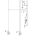
図10は、本発明の第2実施例に係る蒸気処理設備を示す。本第2実施例に係る蒸気処理設備100もまた、図1で説明した圧縮機と電動機から構成された低圧蒸気圧縮部30を採用している。
本第2実施例では、購入蒸気が0t/hとなるように第1低圧蒸気を61.2t/h回収している。また、中圧蒸気ヘッダSMHから第2低圧蒸気ヘッダSLH2へのレットダウンは0t/hとし、第2低圧蒸気ヘッダSLH2から第1低圧蒸気ヘッダSLH1へのレットダウンはヘッダバランスの成り行きで設定する。第2実施例では、購入蒸気が0t/hとなるように第1低圧蒸気56t/hを1.05MPaGに昇圧している。また、第2実施例においても、中圧蒸気で駆動するポンプ60台のうち33台を1.05MPaG仕様に改造し、準中圧蒸気ヘッダSubSMHにつないでいる。本第2実施例では、低圧蒸気圧縮部30は回収された低圧蒸気を使い切っており、余剰の低圧蒸気は生じていない。
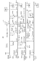
図11は、本発明の第3実施例に係る蒸気処理設備を示す。本第3実施例に係る蒸気処理設備100は、図6で説明した圧縮機と混気タービンから構成された低圧蒸気圧縮部60(混気復水タービン圧縮機)を採用している。
本第3実施例では、各プロセスユニットのケトル型熱交換器38により、第1低圧蒸気を100t/h回収している。また、中圧蒸気ヘッダSMHから第2低圧蒸気ヘッダSLH2へのレットダウンは0t/hとし、第2低圧蒸気ヘッダSLH2から第1低圧蒸気ヘッダSLH1へのレットダウンはヘッダバランスの成り行きで設定する。第3実施例では、購入蒸気が最小となるように、低圧蒸気圧縮部60を用いて第1低圧蒸気57t/hを1.05MPaGに昇圧している。第3実施例では、低圧蒸気圧縮部60の混気タービンへの1.05MPaGの準中圧蒸気の導入量は、0.15MPaGの第1低圧蒸気の導入量の1/4を目標としている。また、第3実施例では、中圧蒸気で駆動するポンプ60台のうち27台を1.05MPaG仕様に改造し、準中圧蒸気ヘッダSubSMHにつないでいる。本第3実施例においても、低圧蒸気圧縮部30は回収された低圧蒸気を使い切っており、余剰の低圧蒸気は生じていない。
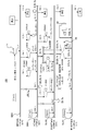
図12は、本発明の第4実施例に係る蒸気処理設備を示す。本第4実施例に係る蒸気処理設備100は、図7で説明した圧縮機、混気タービンおよび電動発電機62から構成された低圧蒸気圧縮部70を採用している。
本第4実施例では、各プロセスユニットのケトル型熱交換器38により、第1低圧蒸気を130t/h回収している。また、中圧蒸気ヘッダSMHから第2低圧蒸気ヘッダSLH2へのレットダウンは0t/hとし、第2低圧蒸気ヘッダSLH2から第1低圧蒸気ヘッダSLH1へのレットダウンはヘッダバランスの成り行きで設定する。第4実施例では、購入蒸気が最小となるように、低圧蒸気圧縮部60を用いて第1低圧蒸気67t/hを1.05MPaGに昇圧している。また、第4実施例では、中圧蒸気で駆動するポンプ60台のうち27台を1.05MPaG仕様に改造し、準中圧蒸気ヘッダSubSMHにつないでいる。本第4実施例においても、低圧蒸気圧縮部30は回収された低圧蒸気を使い切っており、余剰の低圧蒸気は生じていない。
図13は、第1~第3実施例に係る蒸気処理設備のメリットを示す。第1~第3実施例に係る蒸気処理設備100は、従来の低圧蒸気を単純にタービン発電に利用していた蒸気処理設備と比較して、3倍以上の経済的効果を有する。このように、従来購入していた中圧蒸気の少なくとも一部を、プロセス流体を用いて水を加熱蒸発させて発生させた低圧蒸気を昇圧することにより得られた中圧蒸気で代替することにより、プラントを経済的に稼働させることができる。
以上、本発明を実施例をもとに説明した。この実施例は例示であり、それらの各構成要素や各処理プロセスの組合せにいろいろな変形例が可能なこと、またそうした変形例も本発明の範囲にあることは当業者に理解されるところである。
例えば、上述の実施形態では、各プロセスユニット10においてケトル型熱交換器38を用いて冷却水から低圧蒸気を発生させ、該低圧蒸気を中圧蒸気に昇圧する構成とした。これに代えてまたは加えて、各プロセスユニット10で使用した冷却水を回収し、ヒートポンプを用いて回収された冷却水を昇温することで低圧蒸気を発生させ、該低圧蒸気を中圧蒸気に昇圧する構成としてもよい。従来、冷却後の戻り冷却水は、冷却塔等で単純に熱放出による再冷循環使用されていたが、上記のような構成とすることで、熱放出を大幅に減少させ、付加価値の高い蒸気に変換できるので、蒸気処理設備の省エネルギー効果を大幅に向上できる。
SLH1 第1低圧蒸気ヘッダ、 SLH2 第2低圧蒸気ヘッダ、 SLH 低圧蒸気ヘッダ、 SMH 中圧蒸気ヘッダ、 SHH 高圧蒸気ヘッダ、 10 プロセスユニット、 11 ボイラー、 19 中圧蒸気使用装置、 21 低圧蒸気使用装置、 24 圧縮機、 26 電動機、 30、40、50、60、70、80 低圧蒸気圧縮部、 38 ケトル型熱交換器、 45 ラジアルタービン復水発電機、 61 混気タービン、 62 電動発電機、 100 蒸気処理設備。
本発明は、例えば石油精製プラント、石油化学プラント、火力発電プラントなどのプラントに利用することができる。
Claims (12)
- 中圧蒸気を収容する中圧蒸気ヘッダと、
低圧蒸気を収容する低圧蒸気ヘッダと、
前記中圧蒸気ヘッダおよび前記低圧蒸気ヘッダが接続された複数のプロセスユニットと、
前記低圧蒸気ヘッダから供給される低圧蒸気を昇圧して中圧蒸気とし、前記中圧蒸気ヘッダに供給する低圧蒸気圧縮部と、
を備え、
各プロセスユニットで発生した低圧蒸気は、前記低圧蒸気ヘッダに回収され、
前記低圧蒸気ヘッダに回収された低圧蒸気は、前記低圧蒸気圧縮部により中圧蒸気に昇圧された後、前記中圧蒸気ヘッダを介して各プロセスユニットに供給されることを特徴とする蒸気処理設備。 - 前記低圧蒸気圧縮部は、前記低圧蒸気ヘッダからの低圧蒸気を圧縮する圧縮機と、前記低圧蒸気ヘッダからの低圧蒸気を用いて前記圧縮機を起動させる蒸気タービンと、前記蒸気タービンにより前記圧縮機が起動された後に、前記蒸気タービンに代えて前記圧縮機を常時運転させる電動機と、を含むことを特徴とする請求項1に記載の蒸気処理設備。
- 前記低圧蒸気圧縮部は、前記低圧蒸気ヘッダからの低圧蒸気を圧縮する圧縮機と、前記低圧蒸気ヘッダからの低圧蒸気を用いて前記圧縮機を駆動する蒸気タービンと、を含むことを特徴とする請求項1に記載の蒸気処理設備。
- 前記低圧蒸気圧縮部は、前記低圧蒸気ヘッダからの低圧蒸気を圧縮する圧縮機と、前記低圧蒸気ヘッダからの低圧蒸気および前記中圧蒸気ヘッダからの中圧蒸気を用いて前記圧縮機を駆動する混気タービンと、を含むことを特徴とする請求項1に記載の蒸気処理設備。
- 前記低圧蒸気圧縮部は、前記低圧蒸気ヘッダからの低圧蒸気を圧縮する圧縮機と、前記低圧蒸気ヘッダからの低圧蒸気および前記中圧蒸気ヘッダからの中圧蒸気を用いて前記圧縮機を駆動する混気タービンと、前記圧縮機の駆動に必要な動力を超える余剰動力が前記混気タービンで発生した場合に該余剰動力を用いて誘導発電する電動発電機と、を含むことを特徴とする請求項1に記載の蒸気処理設備。
- 前記混気タービンで余剰動力が発生しない場合、前記混気タービンからの動力と前記電動発電機からの動力とを合わせた動力を用いて前記圧縮機が駆動されることを特徴とする請求項5に記載の蒸気処理設備。
- 前記低圧蒸気圧縮部は、前記低圧蒸気ヘッダからの低圧蒸気を圧縮する圧縮機と、前記低圧蒸気ヘッダからの低圧蒸気を用いて前記圧縮機を駆動する蒸気タービンまたは前記低圧蒸気ヘッダからの低圧蒸気および前記中圧蒸気ヘッダからの中圧蒸気を用いて前記圧縮機を駆動する混気タービンと、を備え、
前記蒸気タービンまたは前記混気タービンで生じた真空を用いて、起動の際に前記圧縮機が真空状態とされることを特徴とする請求項1に記載の蒸気処理設備。 - 各プロセスユニットは、プロセス流体を用いて水を加熱蒸発させて低圧蒸気を発生させる熱交換器を備えることを特徴とする請求項1から7のいずれかに記載の蒸気処理設備。
- 各プロセスユニットで使用した冷却水を回収する冷却水回収手段と、
回収された冷却水を昇温して低圧蒸気を発生させるヒートポンプと、
を更に備えることを特徴とする請求項1から8のいずれかに記載の蒸気処理設備。 - 中圧蒸気を収容する中圧蒸気ヘッダと、
低圧蒸気を収容する低圧蒸気ヘッダと、
中圧蒸気と低圧蒸気の間の準中圧蒸気を収容する準中圧蒸気ヘッダと、
前記中圧蒸気ヘッダ、前記低圧蒸気ヘッダおよび前記準中圧蒸気ヘッダが接続された複数のプロセスユニットと、
前記低圧蒸気ヘッダから供給される低圧蒸気を昇圧して準中圧蒸気とし、前記準中圧蒸気ヘッダに供給する低圧蒸気圧縮部と、
を備え、
各プロセスユニットで発生した低圧蒸気は、前記低圧蒸気ヘッダに回収され、
前記低圧蒸気ヘッダに回収された低圧蒸気は、前記低圧蒸気圧縮部により準中圧蒸気に昇圧された後、前記準中圧蒸気ヘッダを介して各プロセスユニットに供給されることを特徴とする蒸気処理設備。 - 中圧蒸気を収容する中圧蒸気ヘッダと、
低圧蒸気を収容する低圧蒸気ヘッダと、
低圧蒸気よりも低い準低圧蒸気を収容する準低圧蒸気ヘッダと、
前記中圧蒸気ヘッダ、前記低圧蒸気ヘッダおよび前記準低圧蒸気ヘッダが接続された複数のプロセスユニットと、
前記準低圧蒸気ヘッダから供給される準低圧蒸気を昇圧して中圧蒸気とし、前記中圧蒸気ヘッダに供給する低圧蒸気圧縮部と、
を備え、
各プロセスユニットで発生した準低圧蒸気は、前記準低圧蒸気ヘッダに回収され、
前記準低圧蒸気ヘッダに回収された準低圧蒸気は、前記低圧蒸気圧縮部により中圧蒸気に昇圧された後、前記中圧蒸気ヘッダを介して各プロセスユニットに供給されることを特徴とする蒸気処理設備。 - 複数のプロセスユニットから低圧蒸気を回収するステップと、
回収された低圧蒸気を昇圧して中圧蒸気とするステップと、
昇圧された中圧蒸気を各プロセスユニットに供給するステップと、
を備えることを特徴とする蒸気処理方法。
Applications Claiming Priority (2)
| Application Number | Priority Date | Filing Date | Title |
|---|---|---|---|
| JP2013-073826 | 2013-03-29 | ||
| JP2013073826A JP6110706B2 (ja) | 2013-03-29 | 2013-03-29 | 蒸気処理設備 |
Publications (1)
| Publication Number | Publication Date |
|---|---|
| WO2014155430A1 true WO2014155430A1 (ja) | 2014-10-02 |
Family
ID=51622531
Family Applications (1)
| Application Number | Title | Priority Date | Filing Date |
|---|---|---|---|
| PCT/JP2013/004401 Ceased WO2014155430A1 (ja) | 2013-03-29 | 2013-07-18 | 蒸気処理設備および蒸気処理方法 |
Country Status (4)
| Country | Link |
|---|---|
| JP (1) | JP6110706B2 (ja) |
| MY (1) | MY178090A (ja) |
| TW (1) | TWI588411B (ja) |
| WO (1) | WO2014155430A1 (ja) |
Cited By (9)
| Publication number | Priority date | Publication date | Assignee | Title |
|---|---|---|---|---|
| CN109027685A (zh) * | 2018-08-07 | 2018-12-18 | 西安热工研究院有限公司 | 利用蒸汽压缩机实现大流量高参数的工业供汽系统及方法 |
| CN109210378A (zh) * | 2018-09-26 | 2019-01-15 | 上海慧得节能科技有限公司 | 一种利用提压消除蒸汽过剩的系统 |
| CN110307044A (zh) * | 2019-07-09 | 2019-10-08 | 长兴永能动力科技有限公司 | 一种蒸汽涡轮增压器 |
| CN111075516A (zh) * | 2019-12-06 | 2020-04-28 | 浙江浙能技术研究院有限公司 | 一种用于蒸汽涡轮增压器的自适应参数变化控制系统及方法 |
| CN111442190A (zh) * | 2019-01-16 | 2020-07-24 | 上海广谋能源技术开发有限公司 | 一种利用地道储能的方法 |
| CN112013277A (zh) * | 2020-09-28 | 2020-12-01 | 王淑雅 | 一种管道蒸汽的分级使用系统 |
| CN114321548A (zh) * | 2022-03-16 | 2022-04-12 | 艾肯(江苏)工业技术有限公司 | 一种蒸汽伴热站用控压分流泵阀组 |
| CN117759873A (zh) * | 2024-02-01 | 2024-03-26 | 瑞纳智能设备股份有限公司 | 蒸汽供应系统 |
| CN119778653A (zh) * | 2025-01-06 | 2025-04-08 | 中国船舶集团有限公司第七一九研究所 | 一种蒸汽安全排放控制方法 |
Families Citing this family (2)
| Publication number | Priority date | Publication date | Assignee | Title |
|---|---|---|---|---|
| JP6715800B2 (ja) * | 2017-06-09 | 2020-07-01 | 出光興産株式会社 | 燃料削減率出力システム、燃料削減率出力方法、および燃料削減率出力プログラム |
| CN110454241A (zh) * | 2019-07-24 | 2019-11-15 | 长兴永能动力科技有限公司 | 一种具有发电或电驱功能的涡轮蒸汽压力匹配器及装置 |
Citations (4)
| Publication number | Priority date | Publication date | Assignee | Title |
|---|---|---|---|---|
| GB1411383A (en) * | 1972-09-11 | 1975-10-22 | Inst De Proiectart Pentru Ind | Thermal power plant |
| JPH0565808A (ja) * | 1991-09-04 | 1993-03-19 | Fuji Electric Co Ltd | 熱併給蒸気タービンプラント |
| JP2008019811A (ja) * | 2006-07-14 | 2008-01-31 | Tlv Co Ltd | プロセス蒸気の制御装置 |
| US20120151924A1 (en) * | 2009-08-24 | 2012-06-21 | Ogilvy Renault Llp/S.E.N.C.R.L., S.R.L. | Method and system for generating high pressure steam |
Family Cites Families (4)
| Publication number | Priority date | Publication date | Assignee | Title |
|---|---|---|---|---|
| JPH10325336A (ja) * | 1997-05-27 | 1998-12-08 | Osaka Gas Co Ltd | ガスタービン発電システム |
| JP3913328B2 (ja) * | 1997-08-26 | 2007-05-09 | 株式会社東芝 | コンバインドサイクル発電プラントの運転方法およびコンバインドサイクル発電プラント |
| JP2007064049A (ja) * | 2005-08-30 | 2007-03-15 | Hitachi Eng Co Ltd | ガスタービンコージェネレーション設備の廃熱回収システム |
| EP2482008B1 (en) * | 2008-01-11 | 2014-10-08 | Johnson Controls Technology Company | Evaporator |
-
2013
- 2013-03-29 JP JP2013073826A patent/JP6110706B2/ja active Active
- 2013-07-18 WO PCT/JP2013/004401 patent/WO2014155430A1/ja not_active Ceased
- 2013-07-18 MY MYPI2015703361A patent/MY178090A/en unknown
- 2013-07-31 TW TW102127466A patent/TWI588411B/zh active
Patent Citations (4)
| Publication number | Priority date | Publication date | Assignee | Title |
|---|---|---|---|---|
| GB1411383A (en) * | 1972-09-11 | 1975-10-22 | Inst De Proiectart Pentru Ind | Thermal power plant |
| JPH0565808A (ja) * | 1991-09-04 | 1993-03-19 | Fuji Electric Co Ltd | 熱併給蒸気タービンプラント |
| JP2008019811A (ja) * | 2006-07-14 | 2008-01-31 | Tlv Co Ltd | プロセス蒸気の制御装置 |
| US20120151924A1 (en) * | 2009-08-24 | 2012-06-21 | Ogilvy Renault Llp/S.E.N.C.R.L., S.R.L. | Method and system for generating high pressure steam |
Cited By (12)
| Publication number | Priority date | Publication date | Assignee | Title |
|---|---|---|---|---|
| CN109027685A (zh) * | 2018-08-07 | 2018-12-18 | 西安热工研究院有限公司 | 利用蒸汽压缩机实现大流量高参数的工业供汽系统及方法 |
| CN109027685B (zh) * | 2018-08-07 | 2023-03-28 | 西安热工研究院有限公司 | 利用蒸汽压缩机实现大流量高参数的工业供汽系统及方法 |
| CN109210378A (zh) * | 2018-09-26 | 2019-01-15 | 上海慧得节能科技有限公司 | 一种利用提压消除蒸汽过剩的系统 |
| CN111442190A (zh) * | 2019-01-16 | 2020-07-24 | 上海广谋能源技术开发有限公司 | 一种利用地道储能的方法 |
| CN111442190B (zh) * | 2019-01-16 | 2021-08-10 | 上海广谋能源技术开发有限公司 | 一种利用地道储能的方法 |
| CN110307044A (zh) * | 2019-07-09 | 2019-10-08 | 长兴永能动力科技有限公司 | 一种蒸汽涡轮增压器 |
| CN111075516A (zh) * | 2019-12-06 | 2020-04-28 | 浙江浙能技术研究院有限公司 | 一种用于蒸汽涡轮增压器的自适应参数变化控制系统及方法 |
| CN112013277A (zh) * | 2020-09-28 | 2020-12-01 | 王淑雅 | 一种管道蒸汽的分级使用系统 |
| CN114321548A (zh) * | 2022-03-16 | 2022-04-12 | 艾肯(江苏)工业技术有限公司 | 一种蒸汽伴热站用控压分流泵阀组 |
| CN114321548B (zh) * | 2022-03-16 | 2022-05-27 | 艾肯(江苏)工业技术有限公司 | 一种蒸汽伴热站用控压分流泵阀组 |
| CN117759873A (zh) * | 2024-02-01 | 2024-03-26 | 瑞纳智能设备股份有限公司 | 蒸汽供应系统 |
| CN119778653A (zh) * | 2025-01-06 | 2025-04-08 | 中国船舶集团有限公司第七一九研究所 | 一种蒸汽安全排放控制方法 |
Also Published As
| Publication number | Publication date |
|---|---|
| JP2014199004A (ja) | 2014-10-23 |
| TWI588411B (zh) | 2017-06-21 |
| JP6110706B2 (ja) | 2017-04-05 |
| MY178090A (en) | 2020-10-02 |
| TW201437559A (zh) | 2014-10-01 |
Similar Documents
| Publication | Publication Date | Title |
|---|---|---|
| JP6110706B2 (ja) | 蒸気処理設備 | |
| US10584614B2 (en) | Waste heat recovery simple cycle system and method | |
| CA2794150C (en) | Heat engines with cascade cycles | |
| AU2011336831C1 (en) | Parallel cycle heat engines | |
| US9976448B2 (en) | Regenerative thermodynamic power generation cycle systems, and methods for operating thereof | |
| US9341086B2 (en) | Cascaded power plant using low and medium temperature source fluid | |
| EP3284920B1 (en) | Hybrid generation system using supercritical carbon dioxide cycle | |
| US9671138B2 (en) | Cascaded power plant using low and medium temperature source fluid | |
| US9784248B2 (en) | Cascaded power plant using low and medium temperature source fluid | |
| JP2016519731A (ja) | 高正味電力の超臨界二酸化炭素回路を有する熱機関システム | |
| JP2016534281A (ja) | 選択的に変更可能な作業流体回路を有する熱機関システム | |
| JP2018517868A (ja) | エネルギー貯蔵の改善 | |
| CN102575531A (zh) | 用于生成高压蒸汽的方法和系统 | |
| JP6793745B2 (ja) | 複合サイクル発電プラント | |
| KR101514621B1 (ko) | 가스 발전 설비 | |
| CN101839154A (zh) | 分布式余热余压发电系统和分布式余热余压发电方法 | |
| US11143102B2 (en) | Waste heat recovery cascade cycle and method | |
| JP2013170553A (ja) | 地熱発電装置 | |
| JP4666641B2 (ja) | エネルギー供給システム、エネルギー供給方法、及びエネルギー供給システムの改造方法 | |
| US20160273410A1 (en) | Thermal power plant with use of the waste heat from a generator | |
| KR102230950B1 (ko) | 스팀히트펌프를 활용한 스팀공급시스템 및 스팀공급방법. | |
| JPH08189309A (ja) | ガスタービンコンバインド・サイクル発電方法 | |
| JP2005030320A (ja) | 発電装置及び発電方法 | |
| JP2017089456A (ja) | 蓄熱式発電装置 | |
| WO2016019927A1 (en) | Thermal energy equipment comprising a steam turbine and an operation method of the thermal energy equipment |
Legal Events
| Date | Code | Title | Description |
|---|---|---|---|
| 121 | Ep: the epo has been informed by wipo that ep was designated in this application |
Ref document number: 13879852 Country of ref document: EP Kind code of ref document: A1 |
|
| NENP | Non-entry into the national phase |
Ref country code: DE |
|
| WWE | Wipo information: entry into national phase |
Ref document number: IDP00201507037 Country of ref document: ID |
|
| 122 | Ep: pct application non-entry in european phase |
Ref document number: 13879852 Country of ref document: EP Kind code of ref document: A1 |