WO2014148446A1 - 電線のシールド構造 - Google Patents
電線のシールド構造 Download PDFInfo
- Publication number
- WO2014148446A1 WO2014148446A1 PCT/JP2014/057197 JP2014057197W WO2014148446A1 WO 2014148446 A1 WO2014148446 A1 WO 2014148446A1 JP 2014057197 W JP2014057197 W JP 2014057197W WO 2014148446 A1 WO2014148446 A1 WO 2014148446A1
- Authority
- WO
- WIPO (PCT)
- Prior art keywords
- shield
- shield material
- outer periphery
- electric wire
- metal fitting
- Prior art date
- Legal status (The legal status is an assumption and is not a legal conclusion. Google has not performed a legal analysis and makes no representation as to the accuracy of the status listed.)
- Ceased
Links
Images


Classifications
-
- H—ELECTRICITY
- H02—GENERATION; CONVERSION OR DISTRIBUTION OF ELECTRIC POWER
- H02G—INSTALLATION OF ELECTRIC CABLES OR LINES, OR OF COMBINED OPTICAL AND ELECTRIC CABLES OR LINES
- H02G3/00—Installations of electric cables or lines or protective tubing therefor in or on buildings, equivalent structures or vehicles
- H02G3/02—Details
- H02G3/04—Protective tubing or conduits, e.g. cable ladders or cable troughs
- H02G3/0462—Tubings, i.e. having a closed section
- H02G3/0481—Tubings, i.e. having a closed section with a circular cross-section
-
- B—PERFORMING OPERATIONS; TRANSPORTING
- B60—VEHICLES IN GENERAL
- B60R—VEHICLES, VEHICLE FITTINGS, OR VEHICLE PARTS, NOT OTHERWISE PROVIDED FOR
- B60R16/00—Electric or fluid circuits specially adapted for vehicles and not otherwise provided for; Arrangement of elements of electric or fluid circuits specially adapted for vehicles and not otherwise provided for
- B60R16/02—Electric or fluid circuits specially adapted for vehicles and not otherwise provided for; Arrangement of elements of electric or fluid circuits specially adapted for vehicles and not otherwise provided for electric constitutive elements
- B60R16/0207—Wire harnesses
-
- H—ELECTRICITY
- H02—GENERATION; CONVERSION OR DISTRIBUTION OF ELECTRIC POWER
- H02G—INSTALLATION OF ELECTRIC CABLES OR LINES, OR OF COMBINED OPTICAL AND ELECTRIC CABLES OR LINES
- H02G3/00—Installations of electric cables or lines or protective tubing therefor in or on buildings, equivalent structures or vehicles
- H02G3/30—Installations of cables or lines on walls, floors or ceilings
- H02G3/32—Installations of cables or lines on walls, floors or ceilings using mounting clamps
Definitions
- the present invention relates to a shield structure for electric wires, specifically, a shield structure in which a plurality of electric wires are collectively surrounded by one shield material.
- the electric wires are covered with a shielding material (such as a braid or foil) in order to prevent propagation of noise such as electromagnetic waves generated from the electric components.
- a shield shell is assembled to the end of the shield material, and noise is grounded by bringing the shield shell into contact with a housing of an electrical component or a body sheet metal panel.
- the number of man-hours for assembling the shield shell can be reduced (see Patent Document 1). .
- the present invention has been made based on this, and the problem to be solved is that it is possible to prevent the propagation of noise of a specific frequency and to prevent the damage of the electric wire and the shield material and the generation of abnormal noise.
- the object is to provide a shield structure for electric wires.
- a wire shield structure includes a cylindrical shield material that collectively surrounds and shields a plurality of wires wired to a vehicle, and is connected to a cylinder end of the shield material.
- the earth metal fitting is formed to be movable along the outer periphery of the shield material.
- a shield structure for an electric wire that can prevent propagation of noise at a specific frequency, and can prevent damage to the electric wire and the shield material and generation of abnormal noise.
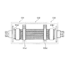
- FIG. 1 is a plan view showing an overall configuration of a wire shield structure according to an embodiment of the present invention.
- FIG. 2 is a diagram schematically showing a shield circuit formed when the ground metal fitting shown in FIG. 1 is arranged.
- FIG. 3 is a diagram schematically showing a shield circuit formed when the mounting position of the grounding metal is changed to be different from the arrangement shown in FIG.
- Such a shield structure is for surrounding and shielding a plurality of electric wires wired to a vehicle with one shield material.
- Each electric wire has a configuration in which the outer periphery of a conductor that is a core wire is covered with an insulating coating.
- the shield structure is wired between a plurality of high-voltage electrical components that are bundled and mounted on a vehicle such as an automobile, for example, between an inverter of an electric motor mounted on a hybrid vehicle and a power supply device.
- the electric wire may have a structure in which two or more layers of conductors and an insulating coating are arranged concentrically.
- FIG. 1 is a plan view showing an overall configuration of an electric wire shield structure according to an embodiment of the present invention.
- the shield structure for shielding the two electric wires 1 is shown as an example, the number of electric wires is not specifically limited, Three or more may be sufficient.
- Each of these electric wires 1 is provided with one connector 2 for sharing each line at both end portions in the extending direction (left and right direction in FIG. 1).
- the connection terminal 21 of the connector 2 is attached to the conductor which peeled and exposed the insulation coating of the terminal part.
- the connector 2 includes a housing 22 that accommodates the connection terminal 21.
- the housing 22 can be accommodated in a state where the connection terminal 21 attached to the terminal portion of the electric wire 1 faces the outside (electrical component side). It has become a structure.
- the shield structure according to the present embodiment includes a cylindrical shield material 3 that collectively surrounds and shields a plurality of electric wires 1, and cylinder end portions 3a and 3b of the shield material 3 connected to the cylindrical end portions 3a and 3b.
- a grounding metal fitting 5 for grounding for grounding.
- the shield material 3 is a conductor formed by forming a braid or a foil into a cylindrical shape, and is arranged so as to surround the outer periphery of the plurality of electric wires 1 between the connectors 2a and 2b.
- FIG. 1 shows a configuration in which a braided conductor is a shield material 3.
- the shield material 3 is formed in an integral cylindrical shape, and has the same cross-sectional shape (for example, the same diameter in the case of a cylindrical shape) over the entire length (dimension with respect to the horizontal direction in FIG. 1).
- the shield material 3 has cylinder end portions 3a and 3b placed on the outer periphery of the shield shell 4, and is crimped and connected to the shield shell 4 by a crimp ring 6 covered by the tube end portions 3a and 3b.
- the shielding material 3 is good also as a structure which covered the outer periphery with the exterior member (protector).
- the shield shell 4 includes a cylindrical connection portion 41 that covers the crimping ring 6 and connects the shield material 3, and a shell fixing portion 42 that extends outwardly from the connection portion 41 in a plate shape. Configured.
- the connecting portion 41 is formed so as to surround the outside of the housing 22 of the connector 2 and is assembled to the housing 22.
- the shell fixing portion 42 is configured to be fixed (for example, fastened and fixed with bolts) to a housing of an electrical component, a sheet metal panel of a vehicle body, or the like.
- the shield shell 4 contacts the shell fixing portion 42 with the housing of the electrical component, the sheet metal panel of the vehicle body, and the like, so that the shield material 3 is grounded (grounded) at the cylindrical end portions 3a and 3b through the shell fixing portion 42. Can be made.
- the ground metal fitting 5 includes a cylindrical metal fitting fastening portion (hereinafter referred to as a fastening portion) 51 that contacts the outer periphery of the shield material 3 and a metal fitting fixing portion (referred to as a fixing portion) that is fixed to a sheet metal panel of the vehicle body. .) 52 is configured.
- the ground metal fitting 5 can be configured as a conductive metal band or clamp.
- a band-shaped metal plate having a conductive property is used as the fastening part 51, and a band formed by forming a through hole in which the fastening part 51 is inserted and locked is applied to the fixing part 52 as the ground metal fitting 5. can do.
- the tightening portion 51 protrudes from one side of the fixing portion 52, and the tightening portion 51 wound around the outer periphery of the shield material 3 is inserted into the through hole of the fixing portion 52 from the other side and pulled out to the one side. And it is sufficient. Then, an engaging claw is provided on the inner surface of the through hole of the fixing portion 52, a serrated engagement groove is formed on the surface of the fastening portion 51, and the engaging claw of the fixing portion 52 is engaged with the fastening portion 51. What is necessary is just to set it as the structure which fastens the earth
- a metal plate having conductivity is bent to form a tightening portion 51 at the bent portion, and both ends of the metal plate are formed so as to be superposed so as to be a fixed portion 52. It can also be applied as the ground metal fitting 5.
- the fastening portion 52 is elastically deformed so as to overlap, so that the fastening portion 51 is elastically deformed so as to be reduced, and the fastening portion 51 is brought into contact with the outer periphery of the shield material 3. It can be set as the structure tightened in a state.
- the fixing portion 52 is formed with a bolt hole 53 for inserting a bolt for fixing the ground metal fitting 5 to a sheet metal panel or the like of the vehicle body. Yes.
- the tightening portion 51 is wound around the outer periphery of the shield member 3, and the tightening portion 51 is inserted into the through hole of the fixing portion 52.
- the fastening portion 51 is attached to the shield material 3 with the fixing portion 52 open, and the grounding metal 5 is elastically deformed so that the fixing portion 52 overlaps. Accordingly, the tightening portion 51 may be reduced to a state where the outer periphery of the shield material 3 is tightened.
- the grounding metal 5 can be fixed to the sheet metal panel or the like with the tightening portion 51 tightening the outer periphery of the shield material 3. .
- the grounding metal 5 is brought into contact with the sheet metal panel or the like of the vehicle body so that the shield member 3 is grounded (grounded) at the intermediate part (between the shield shell 4a and the shield shell 4b) through the fixed part 52. Can be made.
- the fastening portion 51 can be expanded by releasing the engagement between the fastening portion 51 and the fixing portion 52 or by opening the fixing portion 52 from the overlapped state. Therefore, in this state, the ground metal fitting 5 can be moved along the outer periphery of the shield material 3. That is, the mounting position of the grounding metal 5 with respect to the shield material 3 can be easily changed. After changing the mounting position, the grounding metal 5 may be fastened and fixed to the sheet metal panel or the like of the vehicle body with bolts in a state where the tightening portion 51 is reduced and the outer periphery of the shield material 3 is tightened.
- the fixing member 52 is fastened and fixed to the sheet metal panel or the like of the vehicle body with the bolts inserted through the bolt holes 53, so that the ground metal fitting 5 holds the shield material 3 and the plurality of electric wires 1 in a bundled state. It can be fixed to a sheet metal panel. Thereby, even if it is a case where a vehicle vibrates, it can suppress that the bundle
- FIG. 1 shows, as an example, a configuration in which two ground metal fittings 5 are arranged at substantially equal intervals in the middle part of the shield material 3 (between the shield shell 4a and the shield shell 4b).
- the number of the earth metal fittings 5 attached to the shield material 3 can be set arbitrarily, and only one may be sufficient and three or more may be sufficient.
- FIG. 2 schematically shows a shield circuit formed when the ground metal fitting 5 is arranged as shown in FIG.
- a shield circuit C21 is formed between the shield shell 4a and the ground metal 5a
- a shield circuit C22 is formed between the ground metal 5a and the ground metal 5b
- a shield circuit C23 is formed between the shield shell 4b and the ground metal 5b.
- the ground metal fitting 5 can be moved along the outer periphery of the shield material 3, and the mounting position can be easily changed. Therefore, for example, as shown in FIG. 3, it is possible to position the two ground metal fittings 5 in the vicinity of the shield shell 4 and to increase the distance between the two ground metal fittings 5.
- a shield circuit C31 is formed between the shield shell 4a and the ground metal 5a
- a shield circuit C32 is formed between the ground metal 5a and the ground metal 5b
- a shield circuit C33 is formed between the shield shell 4b and the ground metal 5b.
- the size of the shield circuit formed by the earth metal fitting 5 and the shield shell 4 can be changed by changing the mounting position of the earth metal fitting 5.
- the shield circuit C22 is smaller than the shield circuits C21 and C23, and the shield circuit C32 is larger than the shield circuits C31 and C33.
- the shield circuit C22 is smaller than any of the shield circuits C31, C32, and C33.
- a cylindrical shield material (3) that collectively surrounds and shields a plurality of electric wires (1) wired to a vehicle;
- An electric wire shielding structure comprising: an earth fitting (5) attached to an outer periphery of an intermediate portion of the shield material to bundle and hold the shield material and the plurality of electric wires, and to ground the shield material at the intermediate portion.
- the present invention it is possible to realize a shield structure for an electric wire that can prevent propagation of noise at a specific frequency, and can prevent damage to the electric wire and the shield material and generation of abnormal noise.
- the present invention is useful in the field of a shield structure in which a plurality of electric wires are collectively surrounded by one shield material.
Landscapes
- Engineering & Computer Science (AREA)
- Architecture (AREA)
- Civil Engineering (AREA)
- Structural Engineering (AREA)
- Mechanical Engineering (AREA)
- Shielding Devices Or Components To Electric Or Magnetic Fields (AREA)
- Details Of Indoor Wiring (AREA)
Abstract
車両に配線される複数の電線(1)を一括して包囲してシールドする筒状のシールド材(3)と、シールド材の筒端部(3a,3b)に接続されて筒端部でシールド材をアースするシールドシェル(4)と、シールド材の中間部の外周に取り付けられてシールド材及び複数の電線を束ねて保持するとともに、シールド材を中間部でアースするアース金具(5)とを備えたシールド構造とする。
Description
本発明は、電線のシールド構造、具体的には、複数の電線を1つのシールド材で一括して包囲するシールド構造に関する。
例えば、自動車等の車両において電装品間を電線で接続する場合、該電装品から生ずる電磁波等のノイズの伝播を防ぐため、電線をシールド材(編組や箔等)で被覆している。かかるシールド材の端部にはシールドシェルが組み付けられており、該シールドシェルを電装品の筺体や車体板金パネルなどに接触させることで、ノイズをアースさせている。その際、複数の電線を1つのシールド材で一括して包囲し、その端部に単一のシールドシェルを組み付けることで、シールドシェルの組付工数を削減することができる(特許文献1参照)。
しかしながら、このようなシールド構造であっても、特定周波数のノイズを遮断し、かかるノイズの伝播を防止することは難しい。また、複数の電線を1つのシールド材で一括して包囲した場合、これらの電線束が振動によって振れてシールド材が該シールド材の外装部材(プロテクタ)や車体板金などに当たった際の衝撃が大きくなる。この結果、電線及びシールド材の損傷、異音などを生じさせるおそれがある。
本発明はこれを踏まえてなされたものであり、その解決しようとする課題は、特定周波数のノイズの伝播を防止するとともに、電線及びシールド材の損傷、異音の発生を防止することが可能な電線のシールド構造を提供することにある。
上記課題を解決するため、本発明に係る電線のシールド構造は、車両に配線される複数の電線を一括して包囲してシールドする筒状のシールド材と、前記シールド材の筒端部に接続されて前記筒端部で前記シールド材をアースするシールドシェルと、前記シールド材の中間部の外周に取り付けられて前記シールド材及び前記複数の電線を束ねて保持するとともに、前記シールド材を前記中間部でアースするアース金具とを備えることを特徴とする。
この場合、前記アース金具は、前記シールド材の外周に沿って移動可能に形成することが好ましい。
本発明によれば、特定周波数のノイズの伝播を防止するとともに、電線及びシールド材の損傷、異音の発生を防止することが可能な電線のシールド構造を実現することができる。
以下、本発明の電線のシールド構造(以下、単にシールド構造ともいう。)について、添付図面を参照して説明する。かかるシールド構造は、車両に配線される複数の電線を1つのシールド材で包囲してシールドするためのものである。各電線は、芯線である導体の外周が絶縁被覆で被覆された構成となっている。シールド構造は、複数本が束ねられて自動車等の車両に搭載された比較的高圧の電装品間、例えば、ハイブリッド自動車に搭載された電動モータのインバータと電源装置との間などに配線される。なお、電線は、2層以上の導体と絶縁被覆が同心状に配された構造とすることも可能である。
図1は、本発明の一実施形態に係る電線のシールド構造の全体構成を示す平面図である。なお、図1には、2本の電線1をシールドするためのシールド構造を一例として示しているが、電線の本数は特に限定されず、3本以上であっても構わない。これらの電線1には、伸延方向(図1においては、左右方向)の双方の端末部に各線共有のコネクタ2が1つずつ設けられている。そして、各電線1には、端末部の絶縁被覆を剥離して露出させた導体にコネクタ2の接続端子21が取り付けられている。かかる接続端子21が電装品側に設けられた接続端子(図示しない)と接続されることで、電線1は該電装品と導通される。なお、コネクタ2は、接続端子21を収容するハウジング22を備えており、ハウジング22は、電線1の端末部に取り付けられた接続端子21を外部(電装品側)へ臨ませた状態で収容可能な構成となっている。
本実施形態に係るシールド構造は、複数の電線1を一括して包囲してシールドする筒状のシールド材3と、シールド材3の筒端部3a,3bに接続されて該筒端部3a,3bでシールド材3をアース(接地)するシールドシェル4と、シールド材3の中間部の外周に取り付けられてシールド材3及び複数の電線1を束ねて保持するとともに、シールド材3を中間部でアースするアース金具5とを備えている。
シールド材3は、編組や箔を筒状に形成してなる導体であって、コネクタ2a,2bの間で複数の電線1の外周を包囲するように配されている。一例として、図1には、編組導体をシールド材3とした構成を示す。この場合、シールド材3は、一体の筒状に形成され、全長(図1の左右方向に対する寸法)に亘って断面形状が同一(例えば、円筒状であれば、同一径)をなしている。そして、シールド材3は、筒端部3a,3bがシールドシェル4の外周に載置され、該筒端部3a,3bに被冠させた圧着リング6でシールドシェル4に圧着接続されている。なお、シールド材3は、その外周を外装部材(プロテクタ)で覆った構成としてもよい。
シールドシェル4は、圧着リング6を被冠させてシールド材3を接続する筒状の接続部41と、接続部41から外側へ板状に延在するように設けられたシェル固定部42を有して構成されている。接続部41は、コネクタ2のハウジング22の外側を包囲するように形成され、ハウジング22に組み付けられている。シェル固定部42は、電装品の筺体や車体の板金パネル等に固定(例えば、ボルトで締結固定)可能に構成されている。これにより、シールドシェル4は、シェル固定部42を電装品の筺体や車体の板金パネル等に接触させることで、該シェル固定部42を通してシールド材3を筒端部3a,3bでアース(接地)させることができる。
アース金具5は、シールド材3の外周に接触する筒状の金具締付部(以下、締付部という。)51と、車体の板金パネル等に固定される金具固定部(同、固定部という。)52を有して構成されている。例えば、アース金具5は、導電性を有する金属製のバンドやクランプなどとして構成することが可能である。一例として、導線性を有する帯状の金属板を締付部51とし、固定部52には、該締付部51を挿入して係止させる貫通孔を形成してなるバンドをアース金具5として適用することができる。この場合、締付部51を固定部52の一方側から突設し、シールド材3の外周に巻いた締付部51を固定部52の貫通孔へ他方側から挿入して一方側へ引き出す構成とすればよい。そして、固定部52の貫通孔の内面に係合爪を設け、締付部51の表面に鋸歯状の被係合溝を形成し、固定部52の係合爪を締付部51の被係合溝に係合させることで、アース金具5をシールド材3の外周に締め付ける構成とすればよい。また、別の一例として、導電性を有する金属板を折り曲げ加工して、折曲部分に締付部51を形成し、金属板の両端部分を重畳可能に形成して固定部52としたクランプをアース金具5として適用することもできる。かかるアース金具5によれば、固定部52を重畳させるように弾性変形させることで、締付部51が縮小するように弾性変形し、該締付部51をシールド材3の外周に接触させた状態で締め付ける構成とすることができる。なお、アース金具5をバンドもしくはクランプのいずれとした場合であっても、固定部52には、アース金具5を車体の板金パネル等へ固定するボルトを挿通するためのボルト孔53が形成されている。
したがって、アース金具5をシールド材3の外周に取り付ける場合、バンドであれば、締付部51をシールド材3の外周に巻き付け、該締付部51を固定部52の貫通孔に挿入して係合させる。また、クランプであれば、固定部52が開いた状態で締付部51をシールド材3に装着し、固定部52が重畳するようにアース金具5を弾性変形させる。これにより、締付部51を縮小させてシールド材3の外周を締め付けた状態とすればよい。そして、ボルト孔53に挿通したボルトを車体の板金パネル等に締結することで、締付部51がシールド材3の外周を締め付けた状態でアース金具5を該板金パネル等に固定することができる。これにより、アース金具5は、固定部52を車体の板金パネル等に接触させることで、該固定部52を通してシールド材3を中間部(シールドシェル4aとシールドシェル4bの間)でアース(接地)させることができる。
一方で、締付部51と固定部52との係合を解くこと、あるいは、固定部52を重畳させた状態から開いた状態とすることで、締付部51を拡張させることができる。したがって、この状態においては、アース金具5をシールド材3の外周に沿って移動させることができる。すなわち、シールド材3に対するアース金具5の取付位置を容易に変更することができる。取付位置の変更後は、締付部51を縮小させてシールド材3の外周を締め付けた状態で、アース金具5を改めて車体の板金パネル等にボルトで締結固定すればよい。
また、締付部51を締め付けた状態においては、シールド材3で一括して包囲された複数の電線1をシールド材3とともに束ねることができ、アース金具5は、これらのシールド材3及び複数の電線1を束ねた状態で保持することができる。したがって、ボルト孔53に挿通したボルトで固定部52を車体の板金パネル等へ締結固定することで、アース金具5は、シールド材3及び複数の電線1を束ねて保持した状態で、これらを車体の板金パネル等へ固定することができる。これにより、車両が振動した場合であっても、電線1の束が振れることを抑制することができる。この結果、シールド材3がその外装部材(プロテクタ)や車体の板金パネル等に当たることを防止することができ、電線1及びシールド材3の損傷や異音の発生を防止することができる。
ここで、図1には、2つのアース金具5をシールド材3の中間部(シールドシェル4aとシールドシェル4bの間)に略等間隔で配置した構成を一例として示している。なお、シールド材3に取り付けるアース金具5の数は、任意に設定することができ、1つのみでもよいし、3つ以上であっても構わない。図1に示すように、2つのアース金具5を配置した場合、これらのアース金具5の間、及び各アース金具5とシールドシェル4との間にそれぞれシールド回路を形成することができる。図2には、図1に示すようなアース金具5の配置とした場合に形成されるシールド回路を模式的に示す。この場合、シールドシェル4aとアース金具5aとの間にシールド回路C21、アース金具5aとアース金具5bの間にシールド回路C22、シールドシェル4bとアース金具5bとの間にシールド回路C23がそれぞれ形成される。
また、上述したように、アース金具5は、シールド材3の外周に沿って移動させることができ、容易に取付位置を変更することができる。したがって、例えば、図3に示すように、2つのアース金具5をそれぞれシールドシェル4の近傍に位置付け、2つのアース金具5の間隔を広げた配置とすることも可能である。この場合、シールドシェル4aとアース金具5aとの間にシールド回路C31、アース金具5aとアース金具5bの間にシールド回路C32、シールドシェル4bとアース金具5bとの間にシールド回路C33がそれぞれ形成される。
図2及び図3に示すように、アース金具5の取付位置を変更することで、かかるアース金具5及びシールドシェル4によって形成されるシールド回路の大きさを変更させることができる。例えば、シールド回路C22は、シールド回路C21,C23よりも小さく、シールド回路C32は、シールド回路C31,C33よりも大きい。また、シールド回路C22は、シールド回路C31,C32,C33のいずれよりも小さい。このようにシールド回路の大きさを変更させることで、アース金具5及びシールドシェル4でシールド可能な周波数域を変更させることができる。したがって、アース金具5の取付位置を調整することで、電線1が接続される電装品から生ずる電磁波等の特定周波数のノイズを遮断し、かかるノイズの伝播を防止することが可能となる。
ここで、上述した本発明に係るの実施形態の特徴をそれぞれ以下[1]、[2]に簡潔に纏めて列記する。
[1] 車両に配線される複数の電線(1)を一括して包囲してシールドする筒状のシールド材(3)と、
前記シールド材の筒端部(3a,3b)に接続されて前記筒端部で前記シールド材をアースするシールドシェル(4)と、
前記シールド材の中間部の外周に取り付けられて前記シールド材及び前記複数の電線を束ねて保持するとともに、前記シールド材を前記中間部でアースするアース金具(5)とを備える電線のシールド構造。
[2] 前記アース金具は、前記シールド材の外周に沿って移動可能に形成されている上記[1]に記載の電線のシールド構造。
前記シールド材の筒端部(3a,3b)に接続されて前記筒端部で前記シールド材をアースするシールドシェル(4)と、
前記シールド材の中間部の外周に取り付けられて前記シールド材及び前記複数の電線を束ねて保持するとともに、前記シールド材を前記中間部でアースするアース金具(5)とを備える電線のシールド構造。
[2] 前記アース金具は、前記シールド材の外周に沿って移動可能に形成されている上記[1]に記載の電線のシールド構造。
本発明を詳細にまた特定の実施態様を参照して説明したが、本発明の精神と範囲を逸脱することなく様々な変更や修正を加えることができることは当業者にとって明らかである。
本出願は、2013年3月19日出願の日本特許出願(特願2013-057337)に基づくものであり、その内容はここに参照として取り込まれる。
本発明によれば、特定周波数のノイズの伝播を防止するとともに、電線及びシールド材の損傷、異音の発生を防止することが可能な電線のシールド構造を実現することができる。本発明は、複数の電線を1つのシールド材で一括して包囲するシールド構造の分野において有用である。
1 電線
3 シールド材
3a,3b 筒端部
4 シールドシェル
5 アース金具
3 シールド材
3a,3b 筒端部
4 シールドシェル
5 アース金具
Claims (2)
- 車両に配線される複数の電線を一括して包囲してシールドする筒状のシールド材と、
前記シールド材の筒端部に接続されて前記筒端部で前記シールド材をアースするシールドシェルと、
前記シールド材の中間部の外周に取り付けられて前記シールド材及び前記複数の電線を束ねて保持するとともに、前記シールド材を前記中間部でアースするアース金具とを備える電線のシールド構造。 - 前記アース金具は、前記シールド材の外周に沿って移動可能に形成されている請求項1に記載の電線のシールド構造。
Applications Claiming Priority (2)
| Application Number | Priority Date | Filing Date | Title |
|---|---|---|---|
| JP2013057337A JP6180141B2 (ja) | 2013-03-19 | 2013-03-19 | 電線のシールド構造 |
| JP2013-057337 | 2013-03-19 |
Publications (1)
| Publication Number | Publication Date |
|---|---|
| WO2014148446A1 true WO2014148446A1 (ja) | 2014-09-25 |
Family
ID=51580125
Family Applications (1)
| Application Number | Title | Priority Date | Filing Date |
|---|---|---|---|
| PCT/JP2014/057197 Ceased WO2014148446A1 (ja) | 2013-03-19 | 2014-03-17 | 電線のシールド構造 |
Country Status (2)
| Country | Link |
|---|---|
| JP (1) | JP6180141B2 (ja) |
| WO (1) | WO2014148446A1 (ja) |
Cited By (2)
| Publication number | Priority date | Publication date | Assignee | Title |
|---|---|---|---|---|
| WO2020162173A1 (ja) * | 2019-02-07 | 2020-08-13 | 株式会社オートネットワーク技術研究所 | シールド部材 |
| JP2020129651A (ja) * | 2019-02-07 | 2020-08-27 | 株式会社オートネットワーク技術研究所 | シールド部材 |
Families Citing this family (3)
| Publication number | Priority date | Publication date | Assignee | Title |
|---|---|---|---|---|
| JP6394524B2 (ja) * | 2015-07-10 | 2018-09-26 | 株式会社オートネットワーク技術研究所 | 電磁シールド部材及び電磁シールド部材付配線装置 |
| US10993355B2 (en) * | 2016-12-14 | 2021-04-27 | Federal-Mogul Powertrain Llc | Ground strap and method of grounding a plurality of electrically conductive members therewith |
| JP7205078B2 (ja) * | 2018-05-24 | 2023-01-17 | 株式会社村田製作所 | 車載用ワイヤハーネス |
Citations (5)
| Publication number | Priority date | Publication date | Assignee | Title |
|---|---|---|---|---|
| JPS6248618U (ja) * | 1985-09-13 | 1987-03-25 | ||
| JPH02183599A (ja) * | 1989-01-10 | 1990-07-18 | Mitsubishi Electric Corp | シールドケーブルの取付装置 |
| JPH07161394A (ja) * | 1993-12-06 | 1995-06-23 | Sumitomo Wiring Syst Ltd | シールド電線のアース構造 |
| JPH07183052A (ja) * | 1993-12-22 | 1995-07-21 | Kitagawa Ind Co Ltd | 導電性ケーブルバンド |
| JP2012119346A (ja) * | 2010-11-29 | 2012-06-21 | Toyota Motor Corp | シールドカバー |
-
2013
- 2013-03-19 JP JP2013057337A patent/JP6180141B2/ja active Active
-
2014
- 2014-03-17 WO PCT/JP2014/057197 patent/WO2014148446A1/ja not_active Ceased
Patent Citations (5)
| Publication number | Priority date | Publication date | Assignee | Title |
|---|---|---|---|---|
| JPS6248618U (ja) * | 1985-09-13 | 1987-03-25 | ||
| JPH02183599A (ja) * | 1989-01-10 | 1990-07-18 | Mitsubishi Electric Corp | シールドケーブルの取付装置 |
| JPH07161394A (ja) * | 1993-12-06 | 1995-06-23 | Sumitomo Wiring Syst Ltd | シールド電線のアース構造 |
| JPH07183052A (ja) * | 1993-12-22 | 1995-07-21 | Kitagawa Ind Co Ltd | 導電性ケーブルバンド |
| JP2012119346A (ja) * | 2010-11-29 | 2012-06-21 | Toyota Motor Corp | シールドカバー |
Cited By (3)
| Publication number | Priority date | Publication date | Assignee | Title |
|---|---|---|---|---|
| WO2020162173A1 (ja) * | 2019-02-07 | 2020-08-13 | 株式会社オートネットワーク技術研究所 | シールド部材 |
| JP2020129651A (ja) * | 2019-02-07 | 2020-08-27 | 株式会社オートネットワーク技術研究所 | シールド部材 |
| US11464144B2 (en) | 2019-02-07 | 2022-10-04 | Autonetworks Technologies, Ltd. | Shield member |
Also Published As
| Publication number | Publication date |
|---|---|
| JP2014183234A (ja) | 2014-09-29 |
| JP6180141B2 (ja) | 2017-08-16 |
Similar Documents
| Publication | Publication Date | Title |
|---|---|---|
| US9472893B1 (en) | Connector | |
| US6781059B2 (en) | Shielded wire | |
| JP6076505B2 (ja) | 活電部保護構造及びコネクタ | |
| US9469257B2 (en) | Wire harness | |
| CN107710900B (zh) | 屏蔽结构以及屏蔽用编织部件 | |
| JP5412696B2 (ja) | シールドワイヤーハーネス | |
| JP6043577B2 (ja) | シールドコネクタ | |
| JP6188504B2 (ja) | 多芯ケーブルおよび多芯ケーブルの製造方法 | |
| US9592775B2 (en) | Wiring harness protector fixing structure | |
| JP6281448B2 (ja) | 導電路 | |
| JP6210381B2 (ja) | シールド導電路 | |
| JP2006156051A (ja) | 高圧用ワイヤーハーネス | |
| JP2013099184A (ja) | ワイヤハーネス | |
| JP6180141B2 (ja) | 電線のシールド構造 | |
| US8981241B2 (en) | Cable holding structure | |
| WO2013065728A1 (ja) | 電線分岐構造 | |
| CN103392279A (zh) | 保护器及其制造方法和屏蔽导体 | |
| KR102008527B1 (ko) | 차폐 케이블 어셈블리 및 이를 구비하는 커넥터 하우징 어셈블리 | |
| JP2016100200A (ja) | シールド電線及びその製造方法 | |
| JP2013122896A (ja) | 電線のシールドコネクタ接続構造 | |
| JP2013123019A (ja) | 電線のシールド構造 | |
| KR20180062685A (ko) | 차폐수지 전선용 조인트 터미널 및 이를 구비한 차폐수지 적용 전선 | |
| JP6628098B2 (ja) | シールド電線のアース処理構造 | |
| KR20190081692A (ko) | 고전압 케이블의 차폐접지부 및 그 제조방법 | |
| KR101902296B1 (ko) | 차폐수지 전선용 조인트 터미널 및 이를 구비한 차폐수지 적용 전선 |
Legal Events
| Date | Code | Title | Description |
|---|---|---|---|
| 121 | Ep: the epo has been informed by wipo that ep was designated in this application |
Ref document number: 14770352 Country of ref document: EP Kind code of ref document: A1 |
|
| NENP | Non-entry into the national phase |
Ref country code: DE |
|
| 122 | Ep: pct application non-entry in european phase |
Ref document number: 14770352 Country of ref document: EP Kind code of ref document: A1 |