WO2014148192A1 - ガスエンジンの排ガス制御装置 - Google Patents
ガスエンジンの排ガス制御装置 Download PDFInfo
- Publication number
- WO2014148192A1 WO2014148192A1 PCT/JP2014/054052 JP2014054052W WO2014148192A1 WO 2014148192 A1 WO2014148192 A1 WO 2014148192A1 JP 2014054052 W JP2014054052 W JP 2014054052W WO 2014148192 A1 WO2014148192 A1 WO 2014148192A1
- Authority
- WO
- WIPO (PCT)
- Prior art keywords
- nox
- gas
- engine
- operation mode
- ignition timing
- Prior art date
- Legal status (The legal status is an assumption and is not a legal conclusion. Google has not performed a legal analysis and makes no representation as to the accuracy of the status listed.)
- Ceased
Links
Images


Classifications
-
- F—MECHANICAL ENGINEERING; LIGHTING; HEATING; WEAPONS; BLASTING
- F02—COMBUSTION ENGINES; HOT-GAS OR COMBUSTION-PRODUCT ENGINE PLANTS
- F02D—CONTROLLING COMBUSTION ENGINES
- F02D37/00—Non-electrical conjoint control of two or more functions of engines, not otherwise provided for
- F02D37/02—Non-electrical conjoint control of two or more functions of engines, not otherwise provided for one of the functions being ignition
-
- F—MECHANICAL ENGINEERING; LIGHTING; HEATING; WEAPONS; BLASTING
- F01—MACHINES OR ENGINES IN GENERAL; ENGINE PLANTS IN GENERAL; STEAM ENGINES
- F01N—GAS-FLOW SILENCERS OR EXHAUST APPARATUS FOR MACHINES OR ENGINES IN GENERAL; GAS-FLOW SILENCERS OR EXHAUST APPARATUS FOR INTERNAL-COMBUSTION ENGINES
- F01N3/00—Exhaust or silencing apparatus having means for purifying, rendering innocuous, or otherwise treating exhaust
- F01N3/08—Exhaust or silencing apparatus having means for purifying, rendering innocuous, or otherwise treating exhaust for rendering innocuous
- F01N3/10—Exhaust or silencing apparatus having means for purifying, rendering innocuous, or otherwise treating exhaust for rendering innocuous by thermal or catalytic conversion of noxious components of exhaust
- F01N3/18—Exhaust or silencing apparatus having means for purifying, rendering innocuous, or otherwise treating exhaust for rendering innocuous by thermal or catalytic conversion of noxious components of exhaust characterised by methods of operation; Control
- F01N3/20—Exhaust or silencing apparatus having means for purifying, rendering innocuous, or otherwise treating exhaust for rendering innocuous by thermal or catalytic conversion of noxious components of exhaust characterised by methods of operation; Control specially adapted for catalytic conversion
- F01N3/206—Adding periodically or continuously substances to exhaust gases for promoting purification, e.g. catalytic material in liquid form, NOx reducing agents
-
- F—MECHANICAL ENGINEERING; LIGHTING; HEATING; WEAPONS; BLASTING
- F01—MACHINES OR ENGINES IN GENERAL; ENGINE PLANTS IN GENERAL; STEAM ENGINES
- F01N—GAS-FLOW SILENCERS OR EXHAUST APPARATUS FOR MACHINES OR ENGINES IN GENERAL; GAS-FLOW SILENCERS OR EXHAUST APPARATUS FOR INTERNAL-COMBUSTION ENGINES
- F01N9/00—Electrical control of exhaust gas treating apparatus
-
- F—MECHANICAL ENGINEERING; LIGHTING; HEATING; WEAPONS; BLASTING
- F02—COMBUSTION ENGINES; HOT-GAS OR COMBUSTION-PRODUCT ENGINE PLANTS
- F02D—CONTROLLING COMBUSTION ENGINES
- F02D19/00—Controlling engines characterised by their use of non-liquid fuels, pluralities of fuels, or non-fuel substances added to the combustible mixtures
- F02D19/02—Controlling engines characterised by their use of non-liquid fuels, pluralities of fuels, or non-fuel substances added to the combustible mixtures peculiar to engines working with gaseous fuels
-
- F—MECHANICAL ENGINEERING; LIGHTING; HEATING; WEAPONS; BLASTING
- F02—COMBUSTION ENGINES; HOT-GAS OR COMBUSTION-PRODUCT ENGINE PLANTS
- F02D—CONTROLLING COMBUSTION ENGINES
- F02D23/00—Controlling engines characterised by their being supercharged
-
- F—MECHANICAL ENGINEERING; LIGHTING; HEATING; WEAPONS; BLASTING
- F02—COMBUSTION ENGINES; HOT-GAS OR COMBUSTION-PRODUCT ENGINE PLANTS
- F02D—CONTROLLING COMBUSTION ENGINES
- F02D41/00—Electrical control of supply of combustible mixture or its constituents
- F02D41/0025—Controlling engines characterised by use of non-liquid fuels, pluralities of fuels, or non-fuel substances added to the combustible mixtures
- F02D41/0027—Controlling engines characterised by use of non-liquid fuels, pluralities of fuels, or non-fuel substances added to the combustible mixtures the fuel being gaseous
-
- F—MECHANICAL ENGINEERING; LIGHTING; HEATING; WEAPONS; BLASTING
- F02—COMBUSTION ENGINES; HOT-GAS OR COMBUSTION-PRODUCT ENGINE PLANTS
- F02D—CONTROLLING COMBUSTION ENGINES
- F02D41/00—Electrical control of supply of combustible mixture or its constituents
- F02D41/02—Circuit arrangements for generating control signals
- F02D41/021—Introducing corrections for particular conditions exterior to the engine
- F02D41/0235—Introducing corrections for particular conditions exterior to the engine in relation with the state of the exhaust gas treating apparatus
-
- F—MECHANICAL ENGINEERING; LIGHTING; HEATING; WEAPONS; BLASTING
- F02—COMBUSTION ENGINES; HOT-GAS OR COMBUSTION-PRODUCT ENGINE PLANTS
- F02M—SUPPLYING COMBUSTION ENGINES IN GENERAL WITH COMBUSTIBLE MIXTURES OR CONSTITUENTS THEREOF
- F02M21/00—Apparatus for supplying engines with non-liquid fuels, e.g. gaseous fuels stored in liquid form
- F02M21/02—Apparatus for supplying engines with non-liquid fuels, e.g. gaseous fuels stored in liquid form for gaseous fuels
-
- F—MECHANICAL ENGINEERING; LIGHTING; HEATING; WEAPONS; BLASTING
- F02—COMBUSTION ENGINES; HOT-GAS OR COMBUSTION-PRODUCT ENGINE PLANTS
- F02P—IGNITION, OTHER THAN COMPRESSION IGNITION, FOR INTERNAL-COMBUSTION ENGINES; TESTING OF IGNITION TIMING IN COMPRESSION-IGNITION ENGINES
- F02P5/00—Advancing or retarding ignition; Control therefor
- F02P5/04—Advancing or retarding ignition; Control therefor automatically, as a function of the working conditions of the engine or vehicle or of the atmospheric conditions
- F02P5/045—Advancing or retarding ignition; Control therefor automatically, as a function of the working conditions of the engine or vehicle or of the atmospheric conditions combined with electronic control of other engine functions, e.g. fuel injection
-
- F—MECHANICAL ENGINEERING; LIGHTING; HEATING; WEAPONS; BLASTING
- F02—COMBUSTION ENGINES; HOT-GAS OR COMBUSTION-PRODUCT ENGINE PLANTS
- F02P—IGNITION, OTHER THAN COMPRESSION IGNITION, FOR INTERNAL-COMBUSTION ENGINES; TESTING OF IGNITION TIMING IN COMPRESSION-IGNITION ENGINES
- F02P5/00—Advancing or retarding ignition; Control therefor
- F02P5/04—Advancing or retarding ignition; Control therefor automatically, as a function of the working conditions of the engine or vehicle or of the atmospheric conditions
- F02P5/145—Advancing or retarding ignition; Control therefor automatically, as a function of the working conditions of the engine or vehicle or of the atmospheric conditions using electrical means
- F02P5/15—Digital data processing
- F02P5/1502—Digital data processing using one central computing unit
-
- F—MECHANICAL ENGINEERING; LIGHTING; HEATING; WEAPONS; BLASTING
- F02—COMBUSTION ENGINES; HOT-GAS OR COMBUSTION-PRODUCT ENGINE PLANTS
- F02P—IGNITION, OTHER THAN COMPRESSION IGNITION, FOR INTERNAL-COMBUSTION ENGINES; TESTING OF IGNITION TIMING IN COMPRESSION-IGNITION ENGINES
- F02P9/00—Electric spark ignition control, not otherwise provided for
- F02P9/002—Control of spark intensity, intensifying, lengthening, suppression
-
- F—MECHANICAL ENGINEERING; LIGHTING; HEATING; WEAPONS; BLASTING
- F02—COMBUSTION ENGINES; HOT-GAS OR COMBUSTION-PRODUCT ENGINE PLANTS
- F02B—INTERNAL-COMBUSTION PISTON ENGINES; COMBUSTION ENGINES IN GENERAL
- F02B19/00—Engines characterised by precombustion chambers
- F02B19/12—Engines characterised by precombustion chambers with positive ignition
-
- F—MECHANICAL ENGINEERING; LIGHTING; HEATING; WEAPONS; BLASTING
- F02—COMBUSTION ENGINES; HOT-GAS OR COMBUSTION-PRODUCT ENGINE PLANTS
- F02D—CONTROLLING COMBUSTION ENGINES
- F02D19/00—Controlling engines characterised by their use of non-liquid fuels, pluralities of fuels, or non-fuel substances added to the combustible mixtures
- F02D19/06—Controlling engines characterised by their use of non-liquid fuels, pluralities of fuels, or non-fuel substances added to the combustible mixtures peculiar to engines working with pluralities of fuels, e.g. alternatively with light and heavy fuel oil, other than engines indifferent to the fuel consumed
- F02D19/0663—Details on the fuel supply system, e.g. tanks, valves, pipes, pumps, rails, injectors or mixers
- F02D19/0673—Valves; Pressure or flow regulators; Mixers
-
- F—MECHANICAL ENGINEERING; LIGHTING; HEATING; WEAPONS; BLASTING
- F02—COMBUSTION ENGINES; HOT-GAS OR COMBUSTION-PRODUCT ENGINE PLANTS
- F02D—CONTROLLING COMBUSTION ENGINES
- F02D2200/00—Input parameters for engine control
- F02D2200/02—Input parameters for engine control the parameters being related to the engine
- F02D2200/04—Engine intake system parameters
- F02D2200/0414—Air temperature
-
- F—MECHANICAL ENGINEERING; LIGHTING; HEATING; WEAPONS; BLASTING
- F02—COMBUSTION ENGINES; HOT-GAS OR COMBUSTION-PRODUCT ENGINE PLANTS
- F02D—CONTROLLING COMBUSTION ENGINES
- F02D2200/00—Input parameters for engine control
- F02D2200/02—Input parameters for engine control the parameters being related to the engine
- F02D2200/04—Engine intake system parameters
- F02D2200/0418—Air humidity
-
- F—MECHANICAL ENGINEERING; LIGHTING; HEATING; WEAPONS; BLASTING
- F02—COMBUSTION ENGINES; HOT-GAS OR COMBUSTION-PRODUCT ENGINE PLANTS
- F02D—CONTROLLING COMBUSTION ENGINES
- F02D2200/00—Input parameters for engine control
- F02D2200/70—Input parameters for engine control said parameters being related to the vehicle exterior
- F02D2200/701—Information about vehicle position, e.g. from navigation system or GPS signal
-
- F—MECHANICAL ENGINEERING; LIGHTING; HEATING; WEAPONS; BLASTING
- F02—COMBUSTION ENGINES; HOT-GAS OR COMBUSTION-PRODUCT ENGINE PLANTS
- F02D—CONTROLLING COMBUSTION ENGINES
- F02D2250/00—Engine control related to specific problems or objectives
- F02D2250/36—Control for minimising NOx emissions
-
- F—MECHANICAL ENGINEERING; LIGHTING; HEATING; WEAPONS; BLASTING
- F02—COMBUSTION ENGINES; HOT-GAS OR COMBUSTION-PRODUCT ENGINE PLANTS
- F02D—CONTROLLING COMBUSTION ENGINES
- F02D41/00—Electrical control of supply of combustible mixture or its constituents
- F02D41/0002—Controlling intake air
- F02D41/0007—Controlling intake air for control of turbo-charged or super-charged engines
-
- F—MECHANICAL ENGINEERING; LIGHTING; HEATING; WEAPONS; BLASTING
- F02—COMBUSTION ENGINES; HOT-GAS OR COMBUSTION-PRODUCT ENGINE PLANTS
- F02D—CONTROLLING COMBUSTION ENGINES
- F02D41/00—Electrical control of supply of combustible mixture or its constituents
- F02D41/0025—Controlling engines characterised by use of non-liquid fuels, pluralities of fuels, or non-fuel substances added to the combustible mixtures
-
- F—MECHANICAL ENGINEERING; LIGHTING; HEATING; WEAPONS; BLASTING
- F02—COMBUSTION ENGINES; HOT-GAS OR COMBUSTION-PRODUCT ENGINE PLANTS
- F02D—CONTROLLING COMBUSTION ENGINES
- F02D41/00—Electrical control of supply of combustible mixture or its constituents
- F02D41/30—Controlling fuel injection
- F02D41/38—Controlling fuel injection of the high pressure type
- F02D41/40—Controlling fuel injection of the high pressure type with means for controlling injection timing or duration
- F02D41/402—Multiple injections
- F02D41/403—Multiple injections with pilot injections
-
- F—MECHANICAL ENGINEERING; LIGHTING; HEATING; WEAPONS; BLASTING
- F02—COMBUSTION ENGINES; HOT-GAS OR COMBUSTION-PRODUCT ENGINE PLANTS
- F02M—SUPPLYING COMBUSTION ENGINES IN GENERAL WITH COMBUSTIBLE MIXTURES OR CONSTITUENTS THEREOF
- F02M21/00—Apparatus for supplying engines with non-liquid fuels, e.g. gaseous fuels stored in liquid form
- F02M21/02—Apparatus for supplying engines with non-liquid fuels, e.g. gaseous fuels stored in liquid form for gaseous fuels
- F02M21/0218—Details on the gaseous fuel supply system, e.g. tanks, valves, pipes, pumps, rails, injectors or mixers
- F02M21/023—Valves; Pressure or flow regulators in the fuel supply or return system
-
- F—MECHANICAL ENGINEERING; LIGHTING; HEATING; WEAPONS; BLASTING
- F02—COMBUSTION ENGINES; HOT-GAS OR COMBUSTION-PRODUCT ENGINE PLANTS
- F02P—IGNITION, OTHER THAN COMPRESSION IGNITION, FOR INTERNAL-COMBUSTION ENGINES; TESTING OF IGNITION TIMING IN COMPRESSION-IGNITION ENGINES
- F02P13/00—Sparking plugs structurally combined with other parts of internal-combustion engines
-
- Y—GENERAL TAGGING OF NEW TECHNOLOGICAL DEVELOPMENTS; GENERAL TAGGING OF CROSS-SECTIONAL TECHNOLOGIES SPANNING OVER SEVERAL SECTIONS OF THE IPC; TECHNICAL SUBJECTS COVERED BY FORMER USPC CROSS-REFERENCE ART COLLECTIONS [XRACs] AND DIGESTS
- Y02—TECHNOLOGIES OR APPLICATIONS FOR MITIGATION OR ADAPTATION AGAINST CLIMATE CHANGE
- Y02T—CLIMATE CHANGE MITIGATION TECHNOLOGIES RELATED TO TRANSPORTATION
- Y02T10/00—Road transport of goods or passengers
- Y02T10/10—Internal combustion engine [ICE] based vehicles
- Y02T10/30—Use of alternative fuels, e.g. biofuels
-
- Y—GENERAL TAGGING OF NEW TECHNOLOGICAL DEVELOPMENTS; GENERAL TAGGING OF CROSS-SECTIONAL TECHNOLOGIES SPANNING OVER SEVERAL SECTIONS OF THE IPC; TECHNICAL SUBJECTS COVERED BY FORMER USPC CROSS-REFERENCE ART COLLECTIONS [XRACs] AND DIGESTS
- Y02—TECHNOLOGIES OR APPLICATIONS FOR MITIGATION OR ADAPTATION AGAINST CLIMATE CHANGE
- Y02T—CLIMATE CHANGE MITIGATION TECHNOLOGIES RELATED TO TRANSPORTATION
- Y02T10/00—Road transport of goods or passengers
- Y02T10/10—Internal combustion engine [ICE] based vehicles
- Y02T10/40—Engine management systems
Definitions
- the present invention relates to an exhaust gas purification apparatus for a gas engine, and more particularly to an exhaust gas control apparatus effective for suppressing NOx (nitrogen oxide) emission of a gas engine for stationary generator or marine use.
- Patent Document 1 Japanese Patent Application Laid-Open No. 2003-148187
- the ignition timing and the air-fuel ratio of the gas engine are controlled according to the outputs of the fuel composition measuring means, the load measuring means, and the rotational speed measuring means to perform knocking and NOx generation suppression when the fuel composition changes. It is shown.
- Patent Document 1 NOx emissions are suppressed when the fuel composition of the gas engine changes, and it is possible to suppress NOx emissions depending on the environmental condition or geographical condition where the NOx emissions should be suppressed. Not disclosed.
- the present invention performs NOx suppression operation when environmental conditions or geographical conditions necessary to temporarily suppress NOx emissions occur, and places emphasis on fuel consumption in other cases. It is an object of the present invention to provide an exhaust gas control apparatus for a gas engine which can reduce NOx and improve fuel consumption by performing stable operation.
- the present invention controls the ignition timing of the mixed gas supplied into the combustion chamber in an exhaust gas control apparatus of a gas engine that mixes fuel gas and air and supplies the mixed gas to the combustion chamber.
- Ignition timing control means, excess air ratio control means for controlling the excess air ratio in the combustion chamber, and the first set ignition timing and excess air ratio as the optimum fuel consumption rate based on the engine speed and the engine load
- a basic operation mode for controlling the ignition timing control means and the excess air ratio control means with the target ignition timing and the first target excess air ratio as target values, and at least one of environmental conditions, geographical conditions and engine operation progress conditions
- NOx reduction request determination means for determining whether or not to suppress NOx emissions temporarily, and the second target in which the first target ignition timing is delayed.
- An exhaust gas control apparatus for a gas engine comprising: operation mode switching means for switching to the
- the operation mode switching means performs the low NOx operation only when it is necessary to temporarily suppress the NOx emissions due to at least one of the environmental conditions, the geographical conditions and the engine operation progress conditions.
- the control is performed by the excess air ratio control means while switching to the mode and increasing the first target excess air ratio by the second excess air ratio control means, and further, the second target ignition where the first target ignition timing is delayed. Control based on timing is performed by the ignition timing control means.
- An exhaust gas control apparatus for a gas engine can be obtained.
- the NOx reduction requirement determination means needs to make a determination when a photochemical smog alert is issued in the area where the gas engine is installed and in the vicinity thereof.
- the temporary low NOx operation is performed to reduce the amount of NOx emission that is the cause of the photochemical smog.
- the NOx reduction effect can be efficiently obtained without the deterioration of the fuel efficiency during the entire (all operation period) operation.
- the NOx reduction request determination unit determines that the temperature of the outside air where the gas engine is installed is equal to or higher than a predetermined value and the humidity is equal to or lower than a predetermined value.
- the outside air temperature is higher than or equal to the predetermined value and the humidity is higher than the predetermined value in the low humidity condition
- the supplied air temperature is high and NOx is likely to be generated.
- the NOx reduction effect can be obtained efficiently.
- the conditions of high temperature and low humidity are, for example, the case where the air temperature is 30 ° C. or more and the relative humidity is 40% or less.
- the NOx reduction request determination means determines, based on operation aged data of the gas engine, a predetermined period before the next maintenance time or a predetermined period from the first operation start, It is good to make judgment.
- the exhaust gas state tends to deteriorate immediately before the maintenance time for replacing parts of the gas engine, etc., or in such a time, or for a predetermined period from the first operation start In such a time, the NOx reduction operation mode is temporarily switched to perform the NOx reduction operation efficiently, because the exhaust gas state tends to deteriorate regardless of the maintenance time. The reduction effect is obtained.
- the NOx reduction request determination means needs to make a determination when the moving object mounted with the gas engine approaches or enters the NOx emission control area.
- the gas engine is used as a main power source of a power source for a generator mounted on a vehicle or ship as a moving body, or as a main power source of a vehicle or ship as a moving body. If the moving object approaches or enters the NOx emission control area, the NOx reduction operation can be performed temporarily by switching to the low NOx operation mode, and the NOx reduction effect can be performed efficiently. Is obtained.
- the gas engine is equipped with a supercharger, and the low NOx operation mode may control the supercharger to increase the excess air ratio.
- the gas engine has a pilot injection combustion chamber structure, and the increase in excess air ratio in the low NOx operation mode can be reduced by reducing the pilot fuel injected into the auxiliary chamber or the main chamber. Good to do.
- the excess air ratio can be increased by reducing the pilot fuel. This enables operation of NOx reduction. Therefore, when the gas engine has a pilot injection combustion chamber structure, the NOx reduction effect can be efficiently obtained by temporarily switching to the low NOx operation mode and performing the NOx reduction operation.
- the NOx suppression operation is continued and canceled based on the environmental condition required to temporarily suppress the NOx emission and the generation state of the geographical condition, and the NOx suppression operation and the fuel efficiency are emphasized.
- NOx reduction and fuel consumption improvement can be achieved.
- FIG. 2 is a block diagram of an engine control device. It is a control flowchart of an engine control device. It is a flowchart of the subroutine of low NOx mode operation. It is a time chart each of NOx concentration at the time of low NOx mode operation, engine output, ignition timing, and air quantity. It is partial cross section explanatory drawing which shows the combustion chamber structure of 2nd Embodiment of this invention. It is a block diagram of an engine control device of a 2nd embodiment. The modification of 1st, 2nd embodiment is shown.
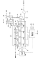
- FIG. 1 shows an overall configuration of a gas engine system according to a first embodiment of the present invention
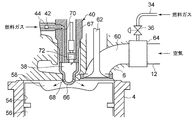
- FIG. 2 is a partial sectional view around a combustion chamber.
- a gas engine with a supercharger for driving a generator will be described as an example, and a configuration having an ignition auxiliary chamber.
- the present invention is not limited to the gas engine of the present embodiment, and can also be applied to the combustion type gas engine of the second embodiment described later.
- the generator 1 is preferable so that a drive object may be shown in figure, it is applicable also in cases other than a generator.
- an engine (gas engine) 2 is provided with a cylinder block 4, a cylinder head 6 and a flywheel 8, and further, a supercharger 10 comprising an exhaust turbine 10 a and a compressor 10 b. Further, the generator 1 is directly attached to the flywheel 8.
- a charge branch 12 is connected to a charge inlet of each cylinder head 6, and each charge branch 12 is connected by a charge outlet of a compressor 10 b and a charge pipe 14.
- the air supply pipe 14 is provided with an air supply cooler 16 that cools the air supplied through the air supply pipe 14.
- an exhaust pipe 18 is connected to an exhaust outlet of each cylinder head 6, and each exhaust pipe 18 is connected by an exhaust inlet of an exhaust turbine 10 a and an exhaust collecting pipe 20.
- An exhaust outlet pipe 22 for discharging the exhaust gas is connected to an exhaust gas outlet of the exhaust turbine 10a.
- an exhaust bypass pipe 24 branched from the inlet side of the exhaust collecting pipe 20 to bypass the exhaust turbine 10a and connected to the exhaust outlet pipe 22 on the outlet side of the exhaust turbine 10a is provided.
- the bus bypass pipe 24 is provided with an exhaust bypass valve 26 that changes the passage area of the exhaust bypass pipe 24 to adjust the supercharging pressure of the compressor 10 b.
- the compressor 10b of the turbocharger 10 is connected to a turbocharger inlet air passage 28 for introducing air from the outside. Further, a gas supply pipe 30 into which the fuel gas is introduced from a fuel gas tank (not shown) for containing the fuel gas is connected to the gas supply main pipe 32 and branched for each cylinder in the middle of the gas supply main pipe 32 A pipe 34 is connected to each air supply branch pipe 12. Further, the fuel gas is pressure-fed to the gas supply main pipe 32 by the gas compressor 31.
- Each gas supply branch 34 is provided with a fuel flow control valve 36 that controls the passage area of each gas supply branch 34, that is, the flow rate of fuel gas. Further, each cylinder head 6 is connected to an auxiliary chamber fuel gas supply pipe 44 for supplying a fuel gas to an ignition device 40 having an auxiliary combustion chamber 38 via a check valve 42.
- a rotational speed sensor 46 for detecting the engine rotational speed, a load sensor 48 for detecting the load of the generator 1, ie, an engine load, a temperature sensor 50 for detecting the outside air temperature, and a humidity sensor 52 for detecting the relative humidity of the outside air are installed. ing.
- FIG. 2 is a partial cross-sectional explanatory view schematically showing a structure around a combustion chamber of the engine 2 of FIG.
- a piston 56 reciprocally slidably fitted in the cylinder 54, a main combustion chamber 58 defined between the upper surface of the piston 56 and the inner surface of the cylinder block 4, and an intake port connected to the main combustion chamber 58 60, an intake valve 62 for opening and closing the intake port 60 and the like.
- a gas mixer 64 is installed on the upstream side of the intake port 60, the gas mixer 64 is connected, the gas supply branch 34 is connected, the fuel gas supplied through the gas supply branch 34, and the charge branch 12 And air supplied through the gas mixer 64 are premixed by the gas mixer 64.
- the gas supply branch pipe 34 may be directly connected to the intake branch pipe 12 without the gas mixer 64 and mixed. Then, it reaches the intake valve 62 through the intake port 60 and is supplied to the main combustion chamber 58 by opening the intake valve 62.
- an auxiliary combustion chamber 38 is formed inside the auxiliary chamber base 66.
- a plurality of injection holes 68 for performing a main combustion by injecting a flame into the main combustion chamber 58 are formed around the tip of the sub-chamber nozzle 66.
- the sub chamber cap 66 is attached to the tip of the nozzle holder 67, and is supplied to the sub chamber fuel gas passage 70 and the sub chamber fuel gas passage 70 inside the nozzle holder 67 into the sub combustion chamber 38.
- a spark plug 72 for igniting the fuel gas is accommodated.
- a fuel gas supply pipe 44 for the sub chamber is connected to the fuel gas passage 70 for the sub chamber, and the fuel gas is supplied into the sub combustion chamber 38 through the check valve 42. The pressurized fuel gas is supplied from the upstream side of the check valve 42 together with the ignition timing of the spark plug 72.
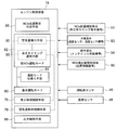
- the engine control device 74 in the gas engine having the above configuration will be described.
- the engine control device 74 mainly controls the ignition timing of the spark plug 72 to ignite the fuel gas supplied into the sub combustion chamber 38, and thereby mixes the mixed gas in the main combustion chamber 58.
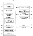
- the operation mode is switched between the basic operation mode 80 and the low NOx operation mode 82.
- the basic operation mode 80 is the optimum for the preset engine speed and engine load based on the signals of the engine speed and the engine load detected from the revolution sensor 46 and the load sensor 48, that is, the most fuel consumption Target excess air ratio (first target excess air ratio) at which the ratio improves, and target excess air ratio (first target excess air ratio) calculated using the table of the map of the target ignition timing (first target ignition timing) It refers to an operation in which the ignition timing control means 76 and the excess air ratio control means 78 are controlled with the target ignition timing (first target ignition timing) as a target value.
- a second target ignition timing obtained by delaying the first target ignition timing by a predetermined amount, and a second target air excess ratio obtained by increasing the first target excess air ratio by a predetermined amount are targeted. It refers to an operation in which the ignition timing control means and the excess air ratio control means are controlled as values.
- the ignition timing retarding means 90 for retarding from the first target ignition timing with good fuel efficiency to the second target ignition timing, and the first target excess air ratio with good fuel efficiency (2) air amount increasing means 92 for increasing the air amount to the target excess air ratio.
- the ignition timing retarding means 90 retards and controls the ignition timing of the spark plug 72. Further, the air amount increasing means 92 squeezes the opening of the exhaust bypass valve 26 of the turbocharger 10 to increase the supercharging amount.
- the NOx reduction request determination means 86 determines whether it is necessary to temporarily suppress the NOx emission amount, such as environmental conditions, geographical conditions, engine operation progress conditions, and the like.
- the engine 2 is subjected to basic exhaust gas measures to clear the exhaust gas regulation value, and the operating conditions (first target ignition timing, first target excess air ratio) with optimal fuel consumption are set thereon.
- the operating conditions first target ignition timing, first target excess air ratio
- fuel consumption will be worsened and uneconomical problems Have.
- the NOx reduction request determination means 86 determines whether or not there has been a response to environmental changes, operating periods, and other special NOx emission regulations.
- the conditions determined by the NOx reduction request determination means 86 are as follows.
- the NOx reduction request determination unit 86 determines that NOx reduction is necessary. judge.
- This photochemical smog alert is often generated in summer in urban areas.
- the amount of power generated by summer is required for power generation equipment. Therefore, at the time of photochemical smog generation in the summer season, it is temporarily necessary to operate while suppressing the amount of NOx emission while maintaining the amount of power generation of the generator constant.
- the low NOx operation mode 82 for NOx reduction is set even if the fuel consumption is deteriorated.
- a gas engine for power generation installed near the urban area it is effective as a means for appropriately operating the relationship between the electric energy increase operation in summer and the NOx reduction operation in consideration of fuel consumption reduction.
- the NOx reduction request determination means also when the outside air temperature at which the engine 2 is installed is a predetermined value or more and the humidity is a high temperature or low humidity state of a predetermined value or less. 86 determines that NOx reduction is necessary.
- the outside air temperature is higher than the predetermined value and the humidity is higher than the predetermined value, the supplied air temperature tends to be high, and the combustion temperature in the main combustion chamber 58 tends to be high, and NOx is generated. Since the situation is easy, temporarily switching to the low NOx operation mode and performing the NOx reduction operation can efficiently obtain the NOx reduction effect.
- conditions of high temperature low humidity the case where air temperature is 30 degreeC or more and whose relative humidity is 40% or less is considered, for example.
- the NOx reduction request determination means 86 determines a predetermined period before the next maintenance time or a predetermined period from the first operation start based on the aged data of the gas engine. It is determined that it is necessary when the period is reached.
- the engine 2 is a gas engine for power generation, and maintenance is regularly performed to replace parts against age-related deterioration, but immediately before the maintenance time, the operation time is extended for a long time.
- the exhaust gas condition tends to deteriorate.
- the NOx reduction effect can be efficiently obtained by switching to the low NOx operation mode temporarily and performing the NOx reduction operation.
- the exhaust gas state tends to deteriorate when a predetermined period from the initial operation start is reached, so temporarily switch to the low NOx operation mode at such time It is effective to perform the NOx reduction operation in the NOx reduction effect.
- the NOx reduction request determination means 86 is installed in the case where the engine 2 is the main power engine of a vehicle, a ship or an aircraft, or in this vehicle, ship or aircraft In the case where a moving body of a vehicle, ship or aircraft approaches or enters a NOx emission control area, for example, when the moving source of a vehicle, ship or aircraft is used as a motive power source for the When moving to the airspace, or moving to an area with strict regulations as a special area in the same country, it is necessary to judge.
- NOx detection is required when entering the area by comparing the detection result of location information with the data of NOx regulation level in the area (including airspace and sea area) of the whole world stored in advance. Determine that there is.
- the NOx reduction level is differentiated between approaching and entering, and one-step NOx reduction is performed when approaching within a certain distance, and further NOx reduction is performed when entering the area. It may be performed stepwise as it is performed. In this way, application to a mobile unit moving to a region where the NOx control value is different is facilitated.
- the determination conditions of the NOx reduction request determination means 86 described above can be determined more appropriately by combining them appropriately. For example, combining the time when the photochemical smog alert under the first condition is issued and the time under the high temperature and low humidity condition of the outside air condition under the second condition makes NOx reduction even more necessary. judge.
- the combination of the high temperature and low humidity state of the second condition, the high temperature and low humidity condition, and the timing immediately before the maintenance timing of the third condition, and the timing immediately before the maintenance timing of the third condition It is particularly effective when approaching or entering the NOx emission control area under eye conditions.
- the operation mode switching unit 84 of the engine control device 74 switches the operation mode from the basic operation mode 80 to the low NOx operation mode 82 when the NOx reduction request determination unit 86 determines that the reduction request is necessary, and reduces If it is determined that the request is not, in the basic operation mode 80, the operation mode is maintained, and if in the low NOx operation mode 82, the basic operation mode 80 is switched back.
- the output control means 88 keeps the output of the generator 1 constant by keeping the engine output, that is, the engine speed constant. In the low NOx operation mode 82, the ignition timing is retarded and the air amount is increased, but the ignition timing delay angle, the air increase amount, and the fuel gas amount are controlled so that the engine output does not greatly fluctuate. .
- step S1 when the operation is started, it is determined in step S1 whether the NOx reduction condition is satisfied. This determination is made by the NOx reduction request determination means 86 whether the total NOx amount regulation issuance signal (photochemical smog issuance signal) 91 is issued or the outside air condition signal (detection signals from the temperature sensor 50 and the humidity sensor 52). Is judged based on the signal (93) that the predetermined high temperature and low humidity state is present.
- the NOx reduction request determination means 86 whether the total NOx amount regulation issuance signal (photochemical smog issuance signal) 91 is issued or the outside air condition signal (detection signals from the temperature sensor 50 and the humidity sensor 52). Is judged based on the signal (93) that the predetermined high temperature and low humidity state is present.
- a secular change signal (a signal indicating that the maintenance period is a predetermined period before the maintenance period from information of the maintenance period signal, or a signal that an elapsed time from the initial operation has reached a predetermined period) 94 .
- a NOx emission control area signal (position information signal) 96, it is performed by determining whether the NOx emission control area is approached or within the range.
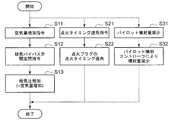
- step S1 The determination in step S1 is repeated until satisfaction of the NOx reduction condition occurs, and when satisfied, the process proceeds to step S2, and the low NOx operation mode is turned ON by the operation mode switching means 84. Thereafter, the process proceeds to step S3 to implement the low NOx operation mode.
- step S4 the transition to the low NOx operation mode is completed by the implementation of the flow shown in FIG.
- step S5 it is determined whether the NOx reduction condition is satisfied as in step S1. If the determination result is "Yes”, the process proceeds to step S6, the low NOx operation mode 82 is continued, and the process is repeated until the NOx reduction condition becomes negative. Then, if the NOx reduction condition is not satisfied, the process proceeds to step S7, and the low NOx operation mode 82 is turned off. Thereafter, the process proceeds to step S8 to cancel the low NOx operation mode.
- the release of the low NOx operation mode is the reverse of the subroutine shown in FIG. 5, and the air amount command value is decreased and the ignition timing is advanced. Then, in step S9, the reverse of the flow shown in FIG. 5 is performed to complete the low NOx operation mode stop and return to the basic operation mode 80.
- step S11 the air amount increasing means 92 is instructed to increase the air amount, and at step S12 the opening of the exhaust bypass valve 26 is operated in the closing direction to supply. Increase air pressure (increase air supply).
- step S21 the ignition timing retarding means 90 is instructed to retard, and in step S22, the ignition timing of the spark plug 72 is retarded.
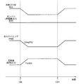
- a time chart in the low NOx operation mode 82 by the above engine control device 74 is shown in FIG. It shows the changes of the NOx concentration in the exhaust gas from ON to OFF of the low NOx operation mode 82, the engine output (generator output), the retardation of the ignition timing, and the air amount increase.
- the ignition timing is retarded at a rate of 2 deg / 5 minutes, and the air amount is increased at a rate of 1% / 5 minutes.
- the engine output is controlled to be maintained substantially constant.
- switching from the time of OFF is performed by returning the air amount and the ignition timing at the same ratio.
- the operation mode is switched only when it is necessary to temporarily suppress the NOx emission amount due to environmental conditions of temperature and humidity, geographical conditions, engine operation progress conditions, etc.
- Control is performed by the excess air ratio control means 78 based on a second target excess air ratio that the means 84 switches from the basic operation mode 80 to the low NOx operation mode 82 and increases the first target excess air ratio. Further, control based on the second target ignition timing, which is the first target ignition timing delayed, is performed by the ignition timing control means 76.
- the second embodiment will be described with reference to FIGS.
- the second embodiment differs from the first embodiment only in the combustion system, and instead of the spark plug type secondary combustion chamber structure of the first embodiment, it has a micro pilot type secondary combustion chamber structure.
- the other configuration is the same as that of the first embodiment, and the same reference numeral is assigned to the same configuration and the description is omitted.
- the auxiliary combustion chamber 38 is formed inside the auxiliary chamber base 66 attached to the tip portion of the nozzle holder 102, and the fuel injection valve 104 is installed inside the nozzle holder 102.
- Liquid fuel is supplied to the fuel injection valve 104 from an inlet pipe 106 for liquid fuel (light oil).
- the premixed mixed gas introduced into the main combustion chamber 58 through the intake valve 62 at the intake stroke passes through the injection hole 68 formed at the tip portion of the sub chamber cap 66 from the main combustion chamber 58 at the compression stroke.
- the liquid fuel is pilot-injected into the mixed gas from the fuel injection valve 104 and burned, and an ignition flame generated by this combustion passes through the injection hole 68 to the main combustion chamber.
- the mixed gas of the premix in the main combustion chamber 58 is burned by causing the fuel to flow back to 58.
- the engine control device 110 is obtained by adding the reduction of the pilot injection amount to the first embodiment as shown by the dotted line portion in FIG.
- the flame strength of the ignition flame is reduced to lower the combustion temperature in the main combustion chamber 58, thereby reducing the NOx generation amount.
- a command to decrease the pilot injection amount is issued in step S31, and the injection amount is decreased by the pilot injection controller (not shown) in step S32.
- the retardation of the ignition timing of the spark plug in steps S21 and S22 in FIG. 5 is replaced with the retardation of the injection timing of the pilot injection.
- the micro pilot sub-combustion chamber structure as in the second embodiment as in the first embodiment, it is necessary to always increase the target excess air ratio and further delay the ignition timing to perform the NOx reduction operation.
- the combustion chamber structure having the sub combustion chamber structure has been described.
- a direct injection structure in which a pilot fuel (liquid fuel) is directly injected into the main combustion chamber may be employed.
- the gas supply pipe 30 to which the fuel gas is introduced from the fuel gas tank (not shown) is connected to the gas supply main pipe 32.
- each cylinder is branched to form a gas supply branch 34 and connected to each air supply branch 12.
- a gas mixer 116 is installed upstream of the compressor 10 b of the turbocharger 10 to supply fuel gas through a gas control valve 118 to generate a premixed mixed gas.
- both the mixing in the supply branch 12 and the mixing upstream of the turbocharger 10 may be provided.
- a gas supply pipe 30 for introducing fuel gas from a fuel gas tank is branched into a turbocharger side gas supply pipe 30a and a cylinder side gas supply pipe 30b, and the turbocharger side gas supply pipe 30a is connected to the gas mixer 116.
- the amount of fuel gas regulated by the gas regulating valve 118 is premixed with air.
- the gas mixer 116 preferably a venturi mixer is used.
- the NOx suppression operation is performed when necessary environmental conditions or geographical conditions occur to temporarily suppress the NOx emission, and stable operation with emphasis on fuel efficiency is performed in other cases.
- NOx reduction and fuel efficiency improvement can be achieved, and therefore, it is suitable for use in a gas engine for power generation or a gas engine provided in a moving body.
Landscapes
- Engineering & Computer Science (AREA)
- Chemical & Material Sciences (AREA)
- Combustion & Propulsion (AREA)
- Mechanical Engineering (AREA)
- General Engineering & Computer Science (AREA)
- Chemical Kinetics & Catalysis (AREA)
- General Chemical & Material Sciences (AREA)
- Oil, Petroleum & Natural Gas (AREA)
- Theoretical Computer Science (AREA)
- Signal Processing (AREA)
- Health & Medical Sciences (AREA)
- Toxicology (AREA)
- Combined Controls Of Internal Combustion Engines (AREA)
- Electrical Control Of Air Or Fuel Supplied To Internal-Combustion Engine (AREA)
- Output Control And Ontrol Of Special Type Engine (AREA)
Priority Applications (4)
| Application Number | Priority Date | Filing Date | Title |
|---|---|---|---|
| KR1020157025570A KR101789897B1 (ko) | 2013-03-19 | 2014-02-20 | 가스 엔진의 배기 가스 제어 장치 |
| EP14767698.5A EP2977595B1 (en) | 2013-03-19 | 2014-02-20 | Exhaust gas control device for a gas engine |
| US14/777,432 US9551285B2 (en) | 2013-03-19 | 2014-02-20 | Exhaust gas control device of gas engine |
| CN201480011512.6A CN105008698B (zh) | 2013-03-19 | 2014-02-20 | 燃气发动机的排气控制装置 |
Applications Claiming Priority (2)
| Application Number | Priority Date | Filing Date | Title |
|---|---|---|---|
| JP2013-056775 | 2013-03-19 | ||
| JP2013056775A JP5980151B2 (ja) | 2013-03-19 | 2013-03-19 | ガスエンジンの排ガス制御装置 |
Publications (1)
| Publication Number | Publication Date |
|---|---|
| WO2014148192A1 true WO2014148192A1 (ja) | 2014-09-25 |
Family
ID=51579884
Family Applications (1)
| Application Number | Title | Priority Date | Filing Date |
|---|---|---|---|
| PCT/JP2014/054052 Ceased WO2014148192A1 (ja) | 2013-03-19 | 2014-02-20 | ガスエンジンの排ガス制御装置 |
Country Status (6)
| Country | Link |
|---|---|
| US (1) | US9551285B2 (enExample) |
| EP (1) | EP2977595B1 (enExample) |
| JP (1) | JP5980151B2 (enExample) |
| KR (1) | KR101789897B1 (enExample) |
| CN (1) | CN105008698B (enExample) |
| WO (1) | WO2014148192A1 (enExample) |
Cited By (3)
| Publication number | Priority date | Publication date | Assignee | Title |
|---|---|---|---|---|
| US9551285B2 (en) | 2013-03-19 | 2017-01-24 | Mitsubishi Heavy Industries, Ltd. | Exhaust gas control device of gas engine |
| NO20161462A1 (en) * | 2015-11-26 | 2017-05-29 | Man Diesel & Turbo Se | Method and control device for operating an engine |
| EP3327280A4 (en) * | 2015-07-23 | 2018-05-30 | Yanmar Co., Ltd. | Engine device |
Families Citing this family (24)
| Publication number | Priority date | Publication date | Assignee | Title |
|---|---|---|---|---|
| US9172217B2 (en) | 2010-11-23 | 2015-10-27 | Woodward, Inc. | Pre-chamber spark plug with tubular electrode and method of manufacturing same |
| US8584648B2 (en) | 2010-11-23 | 2013-11-19 | Woodward, Inc. | Controlled spark ignited flame kernel flow |
| US9476347B2 (en) | 2010-11-23 | 2016-10-25 | Woodward, Inc. | Controlled spark ignited flame kernel flow in fuel-fed prechambers |
| US9856848B2 (en) | 2013-01-08 | 2018-01-02 | Woodward, Inc. | Quiescent chamber hot gas igniter |
| US9765682B2 (en) | 2013-06-10 | 2017-09-19 | Woodward, Inc. | Multi-chamber igniter |
| US20190301351A1 (en) | 2015-08-24 | 2019-10-03 | Akela Industries Inc. | Pre-combustion chamber apparatus and method for pre-combustion |
| JP6561362B2 (ja) * | 2014-10-29 | 2019-08-21 | 株式会社三井E&Sマシナリー | 船舶の機関運転方式 |
| US9653886B2 (en) | 2015-03-20 | 2017-05-16 | Woodward, Inc. | Cap shielded ignition system |
| JP6580701B2 (ja) | 2015-03-20 | 2019-09-25 | ウッドワード, インコーポレーテッドWoodward, Inc. | 並行予燃焼チャンバ点火システム |
| AT517111B1 (de) * | 2015-06-29 | 2016-11-15 | Ge Jenbacher Gmbh & Co Og | Brennkraftmaschine mit einer Regeleinrichtung |
| US9890689B2 (en) * | 2015-10-29 | 2018-02-13 | Woodward, Inc. | Gaseous fuel combustion |
| US10208651B2 (en) * | 2016-02-06 | 2019-02-19 | Prometheus Applied Technologies, Llc | Lean-burn pre-combustion chamber |
| JP6919854B2 (ja) * | 2017-03-31 | 2021-08-18 | 国立研究開発法人 海上・港湾・航空技術研究所 | エンジンの排気制御システム及びそれを搭載した船舶 |
| SE542081C2 (en) * | 2017-04-21 | 2020-02-18 | Scania Cv Ab | Gas Engine, Method for Operating a Gas Engine and Generator Set |
| US10626840B2 (en) * | 2017-06-29 | 2020-04-21 | Ford Global Technologies, Llc | Methods and systems for spark timing control |
| SE542084C2 (en) | 2017-07-14 | 2020-02-25 | Lean Marine Sweden Ab | Method for controlling the propulsion of a ship by determined cylinder top pressure |
| DE102017214092B4 (de) * | 2017-08-11 | 2019-07-04 | Continental Automotive Gmbh | Steuerungsverfahren und Brennkraftmaschine |
| KR102422138B1 (ko) * | 2017-11-01 | 2022-07-18 | 현대자동차주식회사 | 하이브리드 자동차 및 그를 위한 엔진 기동 제어 방법 |
| AT16719U1 (de) * | 2018-12-21 | 2020-07-15 | Innio Jenbacher Gmbh & Co Og | Zylinderkopf für eine Brennkraftmaschine |
| US11415041B2 (en) | 2019-09-16 | 2022-08-16 | Woodward, Inc. | Flame triggered and controlled volumetric ignition |
| CN110778380A (zh) * | 2019-12-04 | 2020-02-11 | 艾克赛尔能源科技江苏有限公司 | 瓦斯发动机尾气处理系统 |
| WO2021163863A1 (zh) * | 2020-02-18 | 2021-08-26 | 潍柴动力股份有限公司 | 一种发动机控制方法及装置 |
| US11739702B2 (en) * | 2021-02-23 | 2023-08-29 | Aramco Services Company | Reheated residual gas ignitor |
| CN114183263B (zh) * | 2021-10-29 | 2024-03-05 | 东风商用车有限公司 | 一种多种控制模式的发动机控制方法 |
Citations (12)
| Publication number | Priority date | Publication date | Assignee | Title |
|---|---|---|---|---|
| JPH11351047A (ja) * | 1998-06-11 | 1999-12-21 | Yanmar Diesel Engine Co Ltd | 内燃機関の制御方法 |
| JP2001107809A (ja) * | 1999-10-06 | 2001-04-17 | Goto Ikueikai | ガス燃料内燃機関 |
| JP2002309986A (ja) * | 2001-04-13 | 2002-10-23 | Sanyo Electric Co Ltd | エンジン制御装置及びそれを用いたエンジン駆動式ヒートポンプ装置 |
| JP2003148781A (ja) | 2001-11-15 | 2003-05-21 | Mitsubishi Electric Corp | 換気装置 |
| JP2003148187A (ja) | 2001-11-12 | 2003-05-21 | Tokyo Gas Co Ltd | 内燃機関の制御装置及び制御方法 |
| JP2003239748A (ja) * | 2002-02-18 | 2003-08-27 | Yanmar Co Ltd | 圧縮自着火式内燃機関 |
| JP2005188369A (ja) * | 2003-12-25 | 2005-07-14 | Yanmar Co Ltd | 空燃比制御システム |
| JP2010007518A (ja) * | 2008-06-25 | 2010-01-14 | Nissan Motor Co Ltd | ディーゼルエンジンの排気浄化装置及び排気浄化方法 |
| JP2011127544A (ja) * | 2009-12-18 | 2011-06-30 | Yanmar Co Ltd | ガスエンジン制御装置 |
| WO2011125976A1 (ja) * | 2010-04-02 | 2011-10-13 | 株式会社マサインタナショナル | 熱機関および該熱機関を用いた発電システム |
| JP2011247238A (ja) * | 2010-05-31 | 2011-12-08 | Mitsubishi Heavy Ind Ltd | ガスエンジン |
| JP2013024047A (ja) * | 2011-07-15 | 2013-02-04 | Daihatsu Diesel Mfg Co Ltd | 燃料噴射弁 |
Family Cites Families (14)
| Publication number | Priority date | Publication date | Assignee | Title |
|---|---|---|---|---|
| JPH08121201A (ja) | 1994-10-27 | 1996-05-14 | Tokyo Gas Co Ltd | ガスエンジンのノッキング制御方法及び装置 |
| JP3337931B2 (ja) * | 1997-01-30 | 2002-10-28 | マツダ株式会社 | 筒内噴射式エンジン |
| JP4026991B2 (ja) | 1999-07-23 | 2007-12-26 | 三洋電機株式会社 | ガスヒートポンプ式空気調和装置 |
| JP2005226621A (ja) | 2004-02-16 | 2005-08-25 | Mitsubishi Heavy Ind Ltd | 計測用エンジンを備えたエンジンシステム及びその運転方法 |
| US7168411B2 (en) | 2004-10-01 | 2007-01-30 | Southwest Research Institute | Closed loop engine control for regulating NOx emissions, using a two-dimensional fuel-air curve |
| DE112006000529B4 (de) * | 2005-03-03 | 2016-02-18 | General Motors Global Technology Operations, Inc. | Verfahren zur Steuerung transienter Lasten zwischen mageren und stöchiometrischen Verbrennungsbetriebsarten von Direkteinspritzmaschinen mit gesteuerter Selbstzündungsverbrennung |
| JP4482491B2 (ja) * | 2005-06-17 | 2010-06-16 | 本田技研工業株式会社 | 内燃機関の制御装置 |
| US7992377B2 (en) * | 2006-12-14 | 2011-08-09 | GM Global Technology Operations LLC | Diesel exhaust control during limp-home mode |
| JP4563443B2 (ja) | 2007-12-14 | 2010-10-13 | 三菱重工業株式会社 | ガスエンジンシステムの制御方法及び該システム |
| JP4599390B2 (ja) | 2007-12-14 | 2010-12-15 | 三菱重工業株式会社 | マイクロパイロット噴射式ガスエンジン |
| JP4616878B2 (ja) | 2007-12-14 | 2011-01-19 | 三菱重工業株式会社 | ガスエンジンシステムの制御方法及び該システム |
| FI124007B (fi) | 2008-12-16 | 2014-01-31 | Waertsilae Finland Oy | Menetelmä ja järjestelmä polttomoottorin päästöjen hallitsemiseksi |
| EP2405120B1 (en) | 2010-03-26 | 2019-07-10 | Toyota Jidosha Kabushiki Kaisha | Combustion controller for internal combustion engine |
| JP5980151B2 (ja) | 2013-03-19 | 2016-08-31 | 三菱重工業株式会社 | ガスエンジンの排ガス制御装置 |
-
2013
- 2013-03-19 JP JP2013056775A patent/JP5980151B2/ja active Active
-
2014
- 2014-02-20 WO PCT/JP2014/054052 patent/WO2014148192A1/ja not_active Ceased
- 2014-02-20 US US14/777,432 patent/US9551285B2/en active Active
- 2014-02-20 KR KR1020157025570A patent/KR101789897B1/ko active Active
- 2014-02-20 CN CN201480011512.6A patent/CN105008698B/zh active Active
- 2014-02-20 EP EP14767698.5A patent/EP2977595B1/en active Active
Patent Citations (12)
| Publication number | Priority date | Publication date | Assignee | Title |
|---|---|---|---|---|
| JPH11351047A (ja) * | 1998-06-11 | 1999-12-21 | Yanmar Diesel Engine Co Ltd | 内燃機関の制御方法 |
| JP2001107809A (ja) * | 1999-10-06 | 2001-04-17 | Goto Ikueikai | ガス燃料内燃機関 |
| JP2002309986A (ja) * | 2001-04-13 | 2002-10-23 | Sanyo Electric Co Ltd | エンジン制御装置及びそれを用いたエンジン駆動式ヒートポンプ装置 |
| JP2003148187A (ja) | 2001-11-12 | 2003-05-21 | Tokyo Gas Co Ltd | 内燃機関の制御装置及び制御方法 |
| JP2003148781A (ja) | 2001-11-15 | 2003-05-21 | Mitsubishi Electric Corp | 換気装置 |
| JP2003239748A (ja) * | 2002-02-18 | 2003-08-27 | Yanmar Co Ltd | 圧縮自着火式内燃機関 |
| JP2005188369A (ja) * | 2003-12-25 | 2005-07-14 | Yanmar Co Ltd | 空燃比制御システム |
| JP2010007518A (ja) * | 2008-06-25 | 2010-01-14 | Nissan Motor Co Ltd | ディーゼルエンジンの排気浄化装置及び排気浄化方法 |
| JP2011127544A (ja) * | 2009-12-18 | 2011-06-30 | Yanmar Co Ltd | ガスエンジン制御装置 |
| WO2011125976A1 (ja) * | 2010-04-02 | 2011-10-13 | 株式会社マサインタナショナル | 熱機関および該熱機関を用いた発電システム |
| JP2011247238A (ja) * | 2010-05-31 | 2011-12-08 | Mitsubishi Heavy Ind Ltd | ガスエンジン |
| JP2013024047A (ja) * | 2011-07-15 | 2013-02-04 | Daihatsu Diesel Mfg Co Ltd | 燃料噴射弁 |
Cited By (4)
| Publication number | Priority date | Publication date | Assignee | Title |
|---|---|---|---|---|
| US9551285B2 (en) | 2013-03-19 | 2017-01-24 | Mitsubishi Heavy Industries, Ltd. | Exhaust gas control device of gas engine |
| EP3327280A4 (en) * | 2015-07-23 | 2018-05-30 | Yanmar Co., Ltd. | Engine device |
| US10221796B2 (en) | 2015-07-23 | 2019-03-05 | Yanmar Co., Ltd. | Engine device |
| NO20161462A1 (en) * | 2015-11-26 | 2017-05-29 | Man Diesel & Turbo Se | Method and control device for operating an engine |
Also Published As
| Publication number | Publication date |
|---|---|
| US20160047323A1 (en) | 2016-02-18 |
| JP2014181614A (ja) | 2014-09-29 |
| EP2977595A1 (en) | 2016-01-27 |
| KR101789897B1 (ko) | 2017-10-25 |
| KR20150119394A (ko) | 2015-10-23 |
| CN105008698A (zh) | 2015-10-28 |
| JP5980151B2 (ja) | 2016-08-31 |
| EP2977595A4 (en) | 2016-12-28 |
| CN105008698B (zh) | 2019-01-01 |
| EP2977595B1 (en) | 2021-04-07 |
| US9551285B2 (en) | 2017-01-24 |
Similar Documents
| Publication | Publication Date | Title |
|---|---|---|
| WO2014148192A1 (ja) | ガスエンジンの排ガス制御装置 | |
| RU2603443C2 (ru) | Способ эксплуатации двигателя (варианты) и система двигателя | |
| EP2652293B1 (en) | Method of operating an internal combustion piston engine in transient load change, a control system for controlling the operating of an internal combustion engine, and a piston engine | |
| US11952935B2 (en) | Systems and method for controlling auto-ignition | |
| RU2678576C2 (ru) | Способ и система для управления энергией зажигания | |
| RU2709856C2 (ru) | Способ (варианты) и система управления турбогенератором путем изменения фаз газораспределения и продолжительности открытия выпускного клапана в двигателе с разветвленной выхлопной системой | |
| US11242784B2 (en) | Method and systems for engine control | |
| JP2014181614A5 (enExample) | ||
| RU2699149C2 (ru) | Способ координации подачи вторичного воздуха и продувочного воздуха в двигатель (варианты) | |
| US9964053B2 (en) | Combustion control device for gas engine | |
| JP7122799B2 (ja) | 大型ディーゼル機関を運転する方法、この方法の使用、及び大型ディーゼル機関 | |
| WO2014076995A1 (ja) | ディーゼルエンジンの制御装置、ディーゼルエンジン、及びディーゼルエンジンの制御方法 | |
| US9822753B2 (en) | Ignition control device | |
| CN102182608A (zh) | 一种缸内直喷汽油机燃烧系统及其控制方法 | |
| US20120017873A1 (en) | Spark advance adjustment | |
| JPWO2015122418A1 (ja) | マルチフューエルエンジンおよびその制御方法 | |
| CN203476523U (zh) | 内燃机稀薄燃烧多次点燃装置 | |
| US11536216B2 (en) | Systems and methods for an engine | |
| US10288002B2 (en) | Lean mode during idling for reduction of the number of particles | |
| RU2017131913A (ru) | Повышение эффективности системы лазерного зажигания | |
| US10465617B2 (en) | Dual-fuel internal combustion engine | |
| JP2016089659A (ja) | 車両の制御装置 | |
| Nam | The Strategies of NOx Emission Reduction for Diesel Engines | |
| JP6494190B2 (ja) | 内燃機関の制御装置 | |
| KR20160072899A (ko) | 듀얼 직분사 엔진의 인젝터 제어 방법 및 장치 |
Legal Events
| Date | Code | Title | Description |
|---|---|---|---|
| 121 | Ep: the epo has been informed by wipo that ep was designated in this application |
Ref document number: 14767698 Country of ref document: EP Kind code of ref document: A1 |
|
| WWE | Wipo information: entry into national phase |
Ref document number: 14777432 Country of ref document: US Ref document number: 2014767698 Country of ref document: EP |
|
| ENP | Entry into the national phase |
Ref document number: 20157025570 Country of ref document: KR Kind code of ref document: A |
|
| NENP | Non-entry into the national phase |
Ref country code: DE |