WO2014147779A1 - 自動変速機の制御装置 - Google Patents
自動変速機の制御装置 Download PDFInfo
- Publication number
- WO2014147779A1 WO2014147779A1 PCT/JP2013/057975 JP2013057975W WO2014147779A1 WO 2014147779 A1 WO2014147779 A1 WO 2014147779A1 JP 2013057975 W JP2013057975 W JP 2013057975W WO 2014147779 A1 WO2014147779 A1 WO 2014147779A1
- Authority
- WO
- WIPO (PCT)
- Prior art keywords
- transmission
- gear
- transmission path
- ratio
- input shaft
- Prior art date
- Legal status (The legal status is an assumption and is not a legal conclusion. Google has not performed a legal analysis and makes no representation as to the accuracy of the status listed.)
- Ceased
Links
Images



Classifications
-
- F—MECHANICAL ENGINEERING; LIGHTING; HEATING; WEAPONS; BLASTING
- F16—ENGINEERING ELEMENTS AND UNITS; GENERAL MEASURES FOR PRODUCING AND MAINTAINING EFFECTIVE FUNCTIONING OF MACHINES OR INSTALLATIONS; THERMAL INSULATION IN GENERAL
- F16H—GEARING
- F16H37/00—Combinations of mechanical gearings, not provided for in groups F16H1/00 - F16H35/00
- F16H37/02—Combinations of mechanical gearings, not provided for in groups F16H1/00 - F16H35/00 comprising essentially only toothed or friction gearings
- F16H37/06—Combinations of mechanical gearings, not provided for in groups F16H1/00 - F16H35/00 comprising essentially only toothed or friction gearings with a plurality of driving or driven shafts; with arrangements for dividing torque between two or more intermediate shafts
- F16H37/08—Combinations of mechanical gearings, not provided for in groups F16H1/00 - F16H35/00 comprising essentially only toothed or friction gearings with a plurality of driving or driven shafts; with arrangements for dividing torque between two or more intermediate shafts with differential gearing
- F16H37/0833—Combinations of mechanical gearings, not provided for in groups F16H1/00 - F16H35/00 comprising essentially only toothed or friction gearings with a plurality of driving or driven shafts; with arrangements for dividing torque between two or more intermediate shafts with differential gearing with arrangements for dividing torque between two or more intermediate shafts, i.e. with two or more internal power paths
- F16H37/084—Combinations of mechanical gearings, not provided for in groups F16H1/00 - F16H35/00 comprising essentially only toothed or friction gearings with a plurality of driving or driven shafts; with arrangements for dividing torque between two or more intermediate shafts with differential gearing with arrangements for dividing torque between two or more intermediate shafts, i.e. with two or more internal power paths at least one power path being a continuously variable transmission, i.e. CVT
- F16H37/0846—CVT using endless flexible members
-
- F—MECHANICAL ENGINEERING; LIGHTING; HEATING; WEAPONS; BLASTING
- F16—ENGINEERING ELEMENTS AND UNITS; GENERAL MEASURES FOR PRODUCING AND MAINTAINING EFFECTIVE FUNCTIONING OF MACHINES OR INSTALLATIONS; THERMAL INSULATION IN GENERAL
- F16H—GEARING
- F16H61/00—Control functions within control units of change-speed- or reversing-gearings for conveying rotary motion ; Control of exclusively fluid gearing, friction gearing, gearings with endless flexible members or other particular types of gearing
- F16H61/02—Control functions within control units of change-speed- or reversing-gearings for conveying rotary motion ; Control of exclusively fluid gearing, friction gearing, gearings with endless flexible members or other particular types of gearing characterised by the signals used
- F16H61/0202—Control functions within control units of change-speed- or reversing-gearings for conveying rotary motion ; Control of exclusively fluid gearing, friction gearing, gearings with endless flexible members or other particular types of gearing characterised by the signals used the signals being electric
- F16H61/0204—Control functions within control units of change-speed- or reversing-gearings for conveying rotary motion ; Control of exclusively fluid gearing, friction gearing, gearings with endless flexible members or other particular types of gearing characterised by the signals used the signals being electric for gearshift control, e.g. control functions for performing shifting or generation of shift signal
-
- F—MECHANICAL ENGINEERING; LIGHTING; HEATING; WEAPONS; BLASTING
- F16—ENGINEERING ELEMENTS AND UNITS; GENERAL MEASURES FOR PRODUCING AND MAINTAINING EFFECTIVE FUNCTIONING OF MACHINES OR INSTALLATIONS; THERMAL INSULATION IN GENERAL
- F16H—GEARING
- F16H61/00—Control functions within control units of change-speed- or reversing-gearings for conveying rotary motion ; Control of exclusively fluid gearing, friction gearing, gearings with endless flexible members or other particular types of gearing
- F16H61/66—Control functions within control units of change-speed- or reversing-gearings for conveying rotary motion ; Control of exclusively fluid gearing, friction gearing, gearings with endless flexible members or other particular types of gearing specially adapted for continuously variable gearings
- F16H61/662—Control functions within control units of change-speed- or reversing-gearings for conveying rotary motion ; Control of exclusively fluid gearing, friction gearing, gearings with endless flexible members or other particular types of gearing specially adapted for continuously variable gearings with endless flexible members
- F16H61/66254—Control functions within control units of change-speed- or reversing-gearings for conveying rotary motion ; Control of exclusively fluid gearing, friction gearing, gearings with endless flexible members or other particular types of gearing specially adapted for continuously variable gearings with endless flexible members controlling of shifting being influenced by a signal derived from the engine and the main coupling
- F16H61/66259—Control functions within control units of change-speed- or reversing-gearings for conveying rotary motion ; Control of exclusively fluid gearing, friction gearing, gearings with endless flexible members or other particular types of gearing specially adapted for continuously variable gearings with endless flexible members controlling of shifting being influenced by a signal derived from the engine and the main coupling using electrical or electronical sensing or control means
-
- F—MECHANICAL ENGINEERING; LIGHTING; HEATING; WEAPONS; BLASTING
- F16—ENGINEERING ELEMENTS AND UNITS; GENERAL MEASURES FOR PRODUCING AND MAINTAINING EFFECTIVE FUNCTIONING OF MACHINES OR INSTALLATIONS; THERMAL INSULATION IN GENERAL
- F16H—GEARING
- F16H37/00—Combinations of mechanical gearings, not provided for in groups F16H1/00 - F16H35/00
- F16H37/02—Combinations of mechanical gearings, not provided for in groups F16H1/00 - F16H35/00 comprising essentially only toothed or friction gearings
- F16H37/021—Combinations of mechanical gearings, not provided for in groups F16H1/00 - F16H35/00 comprising essentially only toothed or friction gearings toothed gearing combined with continuously variable friction gearing
- F16H2037/026—Layouts with particular features of reversing gear, e.g. to achieve compact arrangement
-
- F—MECHANICAL ENGINEERING; LIGHTING; HEATING; WEAPONS; BLASTING
- F16—ENGINEERING ELEMENTS AND UNITS; GENERAL MEASURES FOR PRODUCING AND MAINTAINING EFFECTIVE FUNCTIONING OF MACHINES OR INSTALLATIONS; THERMAL INSULATION IN GENERAL
- F16H—GEARING
- F16H37/00—Combinations of mechanical gearings, not provided for in groups F16H1/00 - F16H35/00
- F16H37/02—Combinations of mechanical gearings, not provided for in groups F16H1/00 - F16H35/00 comprising essentially only toothed or friction gearings
- F16H37/021—Combinations of mechanical gearings, not provided for in groups F16H1/00 - F16H35/00 comprising essentially only toothed or friction gearings toothed gearing combined with continuously variable friction gearing
- F16H37/022—Combinations of mechanical gearings, not provided for in groups F16H1/00 - F16H35/00 comprising essentially only toothed or friction gearings toothed gearing combined with continuously variable friction gearing the toothed gearing having orbital motion
-
- F—MECHANICAL ENGINEERING; LIGHTING; HEATING; WEAPONS; BLASTING
- F16—ENGINEERING ELEMENTS AND UNITS; GENERAL MEASURES FOR PRODUCING AND MAINTAINING EFFECTIVE FUNCTIONING OF MACHINES OR INSTALLATIONS; THERMAL INSULATION IN GENERAL
- F16H—GEARING
- F16H61/00—Control functions within control units of change-speed- or reversing-gearings for conveying rotary motion ; Control of exclusively fluid gearing, friction gearing, gearings with endless flexible members or other particular types of gearing
- F16H61/68—Control functions within control units of change-speed- or reversing-gearings for conveying rotary motion ; Control of exclusively fluid gearing, friction gearing, gearings with endless flexible members or other particular types of gearing specially adapted for stepped gearings
- F16H61/682—Control functions within control units of change-speed- or reversing-gearings for conveying rotary motion ; Control of exclusively fluid gearing, friction gearing, gearings with endless flexible members or other particular types of gearing specially adapted for stepped gearings with interruption of drive
Definitions
- This invention relates to a control device for an automatic transmission in which two different power transmission paths are provided in parallel between an input shaft and an output shaft.
- a general engine used as a driving force source of a vehicle has a characteristic that an output torque increases as the rotational speed increases.
- the driving force required for the vehicle is usually relatively large at low vehicle speeds and relatively small at high vehicle speeds. That is, when a vehicle using an engine as a driving force source travels, torque having a tendency opposite to that of the engine output characteristics is required. Further, when an engine is operated, there are limited operating points at which the efficiency of the engine is improved. Therefore, a vehicle that uses an engine as a driving force source is equipped with a transmission that can appropriately change the gear ratio. Then, by setting the gear ratio appropriately based on the vehicle running state such as the vehicle speed and the accelerator opening with the transmission, the required driving force can be obtained and the engine can be operated at an efficient operating point. It has become.
- the belt-type continuously variable transmission has a power transmission belt and a pair of pulleys whose belt winding radius changes in size by changing the width of a groove around which the belt is wound.
- the gear ratio set between the pair of pulleys is changed steplessly by changing the groove width of each pulley to change the winding radius of the belt.
- Japanese Utility Model Publication No. 62-45455 A configuration related to the belt type continuously variable transmission as described above is described in Japanese Utility Model Publication No. 62-45455.
- the vehicle transmission described in Japanese Utility Model Publication No. 62-45455 has a configuration in which a reduction gear train and a V-belt type continuously variable transmission are provided in parallel between an input shaft and an output shaft. ing.
- Japanese Patent Application Laid-Open No. Sho 62-220754 provides a parallel drive path having a fixed transmission ratio and a continuously variable transmission path having a belt type continuously variable transmission in parallel between an input shaft and an output shaft.
- the invention relates to a control device for a continuously variable transmission with a direct coupling mechanism in which the belt type continuously variable transmission is idled during direct coupling drive.
- the speed ratio of the belt-type continuously variable transmission during the direct drive is lower than the speed ratio that was last set when switching to the direct drive. It is configured to control to the ratio (Low) side.
- Japanese Patent Laid-Open No. Sho 62-220755 provides a parallel drive path having a fixed transmission ratio and a continuously variable transmission path having a belt type continuously variable transmission between an input shaft and an output shaft in parallel.
- the invention relates to a control method for a continuously variable transmission with a direct coupling mechanism in which a belt-type continuously variable transmission is idled during direct coupling driving.
- the control method described in Japanese Patent Application Laid-Open No. 62-220755 discloses that the maximum speed that can be reached when the throttle opening is fully opened at the vehicle speed at that time during the direct drive.
- the gear ratio is controlled in advance.
- Japanese Patent Application Laid-Open No. 63-28740 also provides a parallel drive path having a fixed transmission ratio and a continuously variable transmission path having a belt type continuously variable transmission in parallel between an input shaft and an output shaft.
- the invention relates to a control method for a continuously variable transmission with a direct coupling mechanism in which a belt-type continuously variable transmission is idled during direct coupling driving.
- the speed ratio of the belt-type continuously variable transmission during the direct drive is lower than the speed ratio last set when switching to the direct drive. Control is to the ratio (Low) side.
- the hysteresis width is set so that the engine speed when switching from direct drive to continuously variable drive at the same throttle opening is lower than the engine speed when switching from continuously variable drive to direct drive,
- the speed ratio of the belt type continuously variable transmission is controlled in advance to the high speed ratio (high) side.
- a transmission is configured by arranging other transmission mechanisms such as a stepped transmission mechanism and a gear transmission mechanism in parallel with the belt-type continuously variable transmission mechanism.
- the width of the transmission ratio that can be set for the entire transmission can be increased.
- the power transmission efficiency as the whole transmission can be improved.
- the torque transmitted by the transmission and the moment of inertia of the power transmission path applied to the vehicle change, There is a possibility of giving the driver a shock or a sense of incongruity.
- the belt type continuously variable transmission mechanism idles without being involved in power transmission, the inertial moment of the continuously variable transmission mechanism is large, and accordingly, the power transmission efficiency of the entire transmission is reduced accordingly. .
- an automatic transmission having two different transmission paths in parallel such as a transmission path including a continuously variable transmission mechanism and a transmission path including a stepped transmission mechanism. And when this invention switches the path
- the present invention is applied to the input shaft as the speed ratio set between the input shaft to which torque is input from the power source and the output shaft to output torque to the output member is larger.
- a first transmission path having a first transmission mechanism with a small moment of inertia and a second transmission path having a second transmission mechanism with a different transmission ratio set from the first transmission mechanism are provided in parallel,
- the path for transmitting the power is the first transmission path.
- the control apparatus includes switching means for setting the transmission ratio of the first transmission mechanism to a maximum transmission ratio.
- a normal rotation state in which torque in the same rotation direction as that of the power source is output from the output shaft, and a rotation direction opposite to that of the power source are provided.
- a shift mechanism that selectively sets one of a reverse state in which torque is output from the output shaft and a neutral state in which power transmission between the power source and the output shaft is interrupted can be further provided.
- the switching means according to the present invention is provided when the shift mechanism is operated and switching is performed between at least two of the forward rotation state, the reverse state, and the neutral state.
- the gear ratio of the first transmission mechanism can be set to the maximum gear ratio.
- the switching means according to the present invention is configured such that the first transmission mechanism shifts when the input shaft rotates at a predetermined rotational speed or more and performs the power transmission via the second transmission path.
- the ratio can be configured to be set to the maximum transmission ratio.
- the switching means according to the present invention is configured such that the first transmission mechanism shifts when the input shaft rotates at a predetermined rotational speed or more and performs the power transmission via the second transmission path.
- the ratio can be set to a predetermined gear ratio effective for at least one of vibration suppression and noise suppression of the automatic transmission.
- the first transmission according to the present invention may be configured by a belt-type continuously variable transmission mechanism capable of changing the transmission ratio steplessly by changing the width of the pulley groove around which the transmission belt is wound. it can.
- the transmission path for transmitting power between the input shaft and the output shaft of the automatic transmission is switched from the second transmission path to the first transmission path, it is provided in the first transmission path.
- the largest transmission ratio is set in the first transmission mechanism.
- switching from the second transmission path to the first transmission path is performed in a state where the maximum transmission ratio is set by the first transmission mechanism.
- the first speed change mechanism is configured such that the moment of inertia applied to the input shaft decreases as the speed ratio set there increases. Therefore, the switching from the second transmission path to the first transmission path as described above is performed in a state where the moment of inertia applied to the input shaft is minimized. Therefore, compared with a case where the moment of inertia is large, it is possible to suppress shocks, vibrations, and the like that occur when switching from the second transmission path to the first transmission path.
- the present invention can include a shift mechanism that selectively switches and sets the rotation state of the automatic transmission to a normal rotation state, a reverse rotation state, and a neutral state.
- the gear ratio of the first transmission mechanism is The maximum gear ratio is set. That is, the moment of inertia applied to the input shaft is minimized.
- an engagement shock may occur during the operation of the engagement mechanism in the shift mechanism.
- the moment of inertia applied to the input shaft is minimized as described above. Therefore, compared with a case where the moment of inertia is large, it is possible to suppress engagement shock, vibration, and the like generated by the shift mechanism.
- the transmission ratio of the first transmission mechanism is the maximum speed change. Set to a ratio. That is, the moment of inertia applied to the input shaft is minimized. Therefore, when the automatic transmission is operated in a state where power is transmitted via the second transmission mechanism, for example, when the first transmission mechanism of the first transmission path rotates idly without being involved in torque transmission. Even so, as described above, the moment of inertia applied to the input shaft is minimized. Therefore, loss due to inertia during operation can be reduced as compared with a case where the moment of inertia is large. That is, the power transmission efficiency of the automatic transmission can be improved.
- the transmission ratio of the first transmission mechanism is automatically An effective gear ratio is set to suppress vibration or noise generated in the transmission. That is, the moment of inertia applied to the input shaft is controlled to a magnitude suitable for suppressing vibration and noise.
- this automatic transmission is mounted on a vehicle and the second transmission mechanism is configured by a gear transmission mechanism, vibration and noise due to engine explosion vibration are inevitably generated during operation.
- the moment of inertia applied to the input shaft is controlled to a size effective for suppressing vibration and noise. Therefore, the quietness of a vehicle equipped with this automatic transmission can be improved.
- an automatic transmission in which the first transmission mechanism is a belt-type continuously variable transmission mechanism can be controlled.
- an automatic transmission in which a first transmission path provided with a belt-type continuously variable transmission mechanism and a second transmission path provided with a stepped transmission mechanism constituted by a gear transmission mechanism are provided in parallel is controlled. be able to.
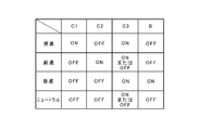
- FIG. 2 is a chart collectively showing operating states of clutch mechanisms and a brake mechanism in the automatic transmission shown in FIG. 1.
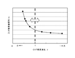
- FIG. 2 is a diagram illustrating a relationship between an equivalent moment of inertia applied to an input shaft and a gear ratio of the belt type continuously variable transmission mechanism when the belt type continuously variable transmission mechanism in the automatic transmission shown in FIG. 1 rotates.
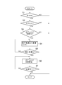
- It is a flowchart for demonstrating an example of the control by the control apparatus of the belt-type continuously variable transmission which concerns on this invention.
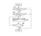
- It is a flowchart for demonstrating the other example of control by the control apparatus of the belt-type continuously variable transmission which concerns on this invention.
- an automatic transmission to be controlled in the present invention includes a first transmission path having a first transmission mechanism and a second transmission path having a second transmission mechanism between an input shaft and an output shaft. Is formed. The first transmission path and the second transmission path are arranged in parallel between the input shaft and the output shaft. Then, either one of the first transmission path and the second transmission path is selected, and the torque is transmitted between the input shaft and the output shaft of the automatic transmission.
- the first transmission mechanism provided in the first transmission path constitutes a main transmission unit of the automatic transmission.
- the first transmission mechanism is constituted by, for example, a belt type continuously variable transmission mechanism.
- the second speed change mechanism provided in the second transmission path constitutes a sub-transmission portion of the automatic transmission.
- the second transmission mechanism is constituted by, for example, a gear transmission mechanism.
- the gear transmission mechanism is configured to set a gear ratio that cannot be set by the belt type continuously variable transmission mechanism. Therefore, the gear transmission mechanism is configured by meshing a plurality of gears, and the gear ratio set by the gear ratio (ratio of the number of teeth) is larger than the maximum gear ratio of the belt-type continuously variable transmission mechanism.
- the speed ratio is smaller than the minimum speed ratio of the belt-type continuously variable transmission mechanism.
- the gear transmission mechanism is a belt-type continuously variable transmission so that a large torque when the vehicle starts is not applied to the belt-type continuously variable transmission mechanism. It is preferable to configure so that a gear ratio larger than the maximum gear ratio of the speed change mechanism can be set. Further, in order to reduce the engine speed in a traveling vehicle and reduce the fuel consumption, the gear transmission mechanism can be configured to be able to set a gear ratio smaller than the minimum gear ratio of the belt-type continuously variable transmission mechanism. preferable.
- FIG. 1 shows an example of a specific configuration of the automatic transmission as described above.
- the automatic transmission 1 to be controlled in the present invention is used by being connected to a power source such as an engine 2.
- a torque converter 3 with a lock-up clutch is connected to the output shaft 2 a of the engine 2.
- This torque converter 3 has a conventionally known configuration.
- a turbine runner 3c is disposed so as to face a pump impeller 3b integrated with the front cover 3a.
- a stator 3e held via a one-way clutch 3d.
- a lock-up clutch 4 that rotates integrally with the turbine runner 3c is disposed to face the inner surface of the front cover 3a. Then, according to the pressure difference between both sides of the lockup clutch 4, the lockup clutch 4 contacts the inner surface of the front cover 3a and transmits the torque, and the torque away from the inner surface of the front cover 3a.
- An open state is set to block transmission of.
- the input shaft 5 of the automatic transmission 1 is connected to the turbine runner 3c in the torque converter 3 described above.
- a forward / reverse switching mechanism 6 is disposed on the same axis as the input shaft 5.
- the forward / reverse switching mechanism 6 has a starting state in which the torque output from the engine 2 is transmitted to a counter shaft 10a (to be described later) without changing its rotational direction, and the rotational direction of the torque output from the engine 2 is reversed. This is a mechanism for switching to the reverse state transmitted to the counter shaft 10a.
- the forward / reverse switching mechanism 6 is constituted by a so-called differential mechanism in which three rotating elements have a differential action.
- the forward / reverse switching mechanism 6 is configured by a double pinion type planetary gear mechanism.
- the double pinion type planetary gear mechanism constituting the forward / reverse switching mechanism 6 meshes with a sun gear 6a as an external gear, a ring gear 6b as an internal gear arranged concentrically with the sun gear 6a, and a sun gear 6a.
- the first pinion gear 6c, the second pinion gear 6c meshed with the first pinion gear 6c and the ring gear 6b, and the carrier 6e holding the first pinion gear 6c and the second pinion gear 6d so as to rotate and revolve.
- the input shaft 5 is connected to the sun gear 6a. Therefore, the sun gear 6a is an input element.
- a brake mechanism B that selectively stops the rotation of the ring gear 6b is provided. Therefore, the ring gear 6b is a reaction force element.
- the brake mechanism B is provided between a fixed part 7 such as a casing and the ring gear 6b.
- the brake mechanism B can be constituted by, for example, a friction brake such as a multi-plate brake or a meshing brake.
- the carrier 6e is an output element.
- a first clutch mechanism C1 for connecting the carrier 6e and the sun gear 6a to integrally rotate the entire planetary gear mechanism.
- the first clutch mechanism C1 is for setting the forward / reverse switching mechanism 6 to a forward state.
- the first clutch mechanism C1 only needs to be capable of selectively transmitting and interrupting torque. Therefore, the first clutch mechanism C1 may be either a friction clutch or a meshing clutch. However, it is preferable that the transmission torque capacity is configured by a friction clutch that gradually increases or decreases according to the engagement force.
- a belt type continuously variable transmission mechanism (CVT) 8 is disposed at the end of the input shaft 5 opposite to the engine 2 (left side in the example shown in FIG. 1).
- This CVT 8 has a conventionally known configuration. That is, a primary pulley 8a that is a driving side rotating member, a secondary pulley 8b that is a driven side rotating member, and a belt 8c wound around the primary pulley 8a and the secondary pulley 8b are provided.
- the primary pulley 8a and the secondary pulley 8b are configured such that the winding radius of the belt 8c changes to a large or small value by changing the width of the groove around which the belt 8c is wound. That is, the gear ratio is changed by changing the width of the groove around which the belt 8c is wound.
- the primary pulley 8a is arranged on the same axis as the input shaft 5 on the opposite side to the engine 2 with the forward / reverse switching mechanism 6 interposed therebetween.
- a primary shaft 8 d integrated with the primary pulley 8 a is connected to a sun gear 6 a that is an input element in the forward / reverse switching mechanism 6.
- the secondary pulley 8b is arranged so that the rotation center axis thereof is parallel to the rotation center axis of the primary pulley 8a.
- the secondary shaft 8e provided along the rotation center axis line of the secondary pulley 8b is provided.
- the output shaft 9 is arrange
- a second clutch mechanism C2 for selectively connecting the output shaft 9 and the secondary shaft 8e is provided.
- the second clutch mechanism C2 may be any mechanism that can selectively transmit and block torque between the secondary pulley 8b and the output shaft 9. Therefore, either a friction clutch or a meshing clutch may be used. However, it is preferable that the transmission torque capacity is configured by a friction clutch that gradually increases or decreases according to the engagement force.
- a gear train 10 is arranged in parallel with the CVT 8 described above.
- the gear train 10 is a gear transmission mechanism composed of a plurality of gears.
- the gear train 10 is configured as a speed change mechanism having a different speed ratio to be set from the CVT 8. Specifically, it is configured as a speed reduction mechanism that sets a speed ratio larger than the maximum speed ratio that can be set by CVT8, or a speed increase mechanism that sets a speed ratio that is smaller than the minimum speed ratio that can be set by CVT8.
- the gear train 10 is configured as a speed reduction mechanism.
- the CVT 8 has a configuration in which the moment of inertia applied to the input shaft 5 decreases as the gear ratio to be set increases, and corresponds to the first transmission mechanism in the present invention.
- the gear train 10 has a different speed ratio setting from the CVT 8 as described above, and corresponds to the second speed change mechanism in the present invention. Therefore, the transmission path provided with the above CVT 8, that is, the transmission path from the input shaft 5 to the output shaft 9 via the primary pulley 8a and the secondary pulley 8b of the CVT 8 corresponds to the first transmission path in the present invention. .
- the transmission path provided with the gear train 10, that is, the transmission path from the input shaft 9 to the output shaft 9 through the gear train 10 corresponds to the second transmission path in the present invention.
- the gear train 10 has a counter shaft 10a disposed in parallel to the input shaft 5 and the output shaft 9, respectively.
- a counter driven gear 10b is attached to one end (right side in the example shown in FIG. 1) of the counter shaft 10a so as to rotate integrally with the counter shaft 10a.
- the counter driven gear 10b meshes with the drive gear 6f that rotates integrally with the carrier 6e of the forward / reverse switching mechanism 6 described above.
- the counter driven gear 10b is a gear having a larger diameter than the drive gear 6f. Therefore, torque is amplified and transmitted in the direction from the drive gear 6f to the counter driven gear 10b.
- a counter drive gear 10c is attached to the other end (left side in the example shown in FIG. 1) of the counter shaft 10a so as to rotate integrally with the counter shaft 10a.
- the counter drive gear 10c is a gear having a smaller diameter than the counter driven gear 10b.
- the counter drive gear 10c is meshed with a driven gear 10d arranged so as to be able to rotate relative to the output shaft 9 on the output shaft 9 described above.
- the driven gear 10d has a larger diameter than the counter drive gear 10c. Therefore, torque is amplified and transmitted in the direction from the driven gear 10d to the counter drive gear 10c.
- the gear ratio (gear ratio) of the gear train 10 is obtained by multiplying the gear ratio between the drive gear 6f and the counter driven gear 10b and the gear ratio between the counter drive gear 10c and the driven gear 10d. It becomes.
- the gear ratio of the gear train 10 is configured such that the value is larger than the maximum gear ratio of the CVT 8.
- a third clutch mechanism C3 for selectively setting a state in which the driven gear 10d is connected to the output shaft 9 so that power can be transmitted and a state in which the power transmission between the driven gear 10d and the output shaft 9 is interrupted.
- the third clutch mechanism C3 may be configured to switch to two states of engagement and release. That is, there is no need for a configuration in which the transmission torque capacity gradually changes. Therefore, the third clutch mechanism C3 can be configured by a meshing clutch such as a dog clutch or a synchronizer. In the example shown in FIG.
- the third clutch mechanism C3 is configured such that the sleeve is fitted to a spline formed on the boss portion of the driven gear 10d and a spline formed on the hub of the output shaft 9, thereby Is connected to the output shaft 9 by a synchronizer.
- the output gear 9a is attached to the end of the output shaft 9 opposite to the CVT 8 (right side in the example shown in FIG. 1).
- a large-diameter gear 11a meshing with the output gear 9a is attached to one end (right side in the example shown in FIG. 1) of the reduction gear shaft 11b.
- a small-diameter gear 11c is attached to the other end (left side in the example shown in FIG. 1) of the reduction gear shaft 11b.
- the small diameter gear 11c meshes with the ring gear 12a of the differential 12.
- the differential 12 is configured to transmit the torque transmitted through the ring gear 12a from the left and right drive shafts 13 to drive wheels (not shown).
- An electronic control unit (ECU) 14 that controls the operation of the automatic transmission 1 is provided.
- the ECU 14 is mainly composed of a microcomputer. Then, calculation is performed in accordance with a predetermined program based on the input data and data stored in advance, and various states such as forward, reverse, or neutral, and control such as setting of a required gear ratio are executed. It is configured.
- the ECU 14 is configured to receive detection signals and information signals from various sensors.
- a pulley rotational speed sensor (not shown) that detects the rotational speeds of the primary pulley 8a and the secondary pulley 8b
- a shift position sensor (not shown) that detects a shift position selected by a shift device or a shift lever
- a detection signal from a wheel speed sensor (not shown) or the like that detects the rotational speed of each wheel of the vehicle in order to obtain the vehicle speed is input to the ECU 14.
- the automatic transmission 1 configured as described above passes through a torque transmission path (that is, the second transmission path in the present invention) provided with the gear train 10 when starting in the forward direction and when traveling backward.
- a torque transmission path that is, the second transmission path in the present invention
- the torque is transmitted to the output shaft 9.
- torque transmission path provided with the CVT 8 (that is, the first transmission path in the present invention).
- the drive position is selected by a shift device or a shift lever (not shown)
- the first clutch mechanism C1 and the third clutch mechanism C3 are engaged, and the second clutch mechanism C2 and the brake mechanism B are released.
- the torque output by the engine 2 is transmitted to the sun gear 6a of the forward / reverse switching mechanism 6 via the input shaft 5 by setting each engagement mechanism as shown in the table of FIG. The Further, it is transmitted to the carrier 6e through the first clutch mechanism C1.
- the forward / reverse switching mechanism 6 transmits the input torque from the carrier 6e to the drive gear 6f without causing any speed increasing action and speed reducing action.
- the driven gear 10d in the gear train 10 is connected to the output shaft 9 by the third clutch mechanism C3
- the torque of the input shaft 5 is transmitted to the output shaft 9 via the gear train 10. Then, torque is transmitted from the output gear 9a to the left and right drive wheels via the gear train 11 and the differential 12, and the vehicle starts.
- the gear train 10 functions as a speed reduction mechanism.
- the gear ratio is larger than the maximum gear ratio that can be set by the CVT 8.
- the CVT 8 is not subjected to a large torque at the start. For this reason, it is not necessary to increase the hydraulic pressure for setting the transmission torque capacity of the CVT 8. Therefore, consumption of power for generating hydraulic pressure is reduced, fuel consumption can be improved, and durability of CVT 8 can be improved.
- the first clutch mechanism C1 When the vehicle speed is increased to a predetermined vehicle speed after starting, the first clutch mechanism C1 is released with the gear ratio of the CVT 8 set to the maximum gear ratio or a gear ratio close thereto. At the same time, the second clutch mechanism C2 is engaged. In this case, the forward / reverse switching mechanism 6 is in a state of so-called free rotation because the first clutch mechanism C1 is further released while the brake mechanism B is released. As a result, power transmission between the input shaft 5 and the gear train 10 is interrupted. On the other hand, the secondary pulley 8b is connected to the output shaft 9 by the second clutch mechanism C2. As a result, the input shaft 5 and the output shaft 9 are coupled so as to transmit torque via the CVT 8. Therefore, the engine speed can be set to a speed with good fuel consumption by gradually decreasing the gear ratio by the CVT 8 or changing it according to the vehicle speed and the accelerator opening.
- the gear ratio in this case is a gear ratio obtained by multiplying the gear ratio by the gear train 10 and the gear ratio by the planetary gear mechanism constituting the forward / reverse switching mechanism 6. Then, torque is transmitted from the output gear 9a to the left and right drive wheels via the gear train 11 and the differential 12, and the vehicle travels backward.
- the neutral state in which the power transmission between the engine 2 and the output shaft 9 is interrupted can be set by opening both the first clutch mechanism C1 and the second clutch mechanism C2. It can.
- the engagement / release state of the first clutch mechanism C1, the second clutch mechanism C2, the third clutch mechanism C3, and the brake mechanism B, and controlling the operation of the forward / reverse switching mechanism 6, A forward state, a reverse state, and a neutral state can be set, respectively.
- a forward rotation state in which torque in the same rotational direction as that of the power source is output from the output shaft 9 a reverse state in which torque in the rotation direction opposite to that of the power source is output from the output shaft 9, and a relationship between the power source and the output shaft 9
- Any of the neutral states that cut off the power transmission between them can be selectively set.
- the first clutch mechanism C1, the second clutch mechanism C2, the third clutch mechanism C3, the brake mechanism B, and the forward / reverse switching mechanism 6 correspond to the shift mechanism in the present invention.
- the automatic transmission 1 to be controlled in the present invention performs clutch-to-clutch control when switching between the transmission path provided with the CVT 8 and the transmission path provided with the gear train 10. By executing this, it is possible to suppress the engagement shock in the engagement mechanism at the time of switching.
- a shift shock is inevitably generated due to a difference in the moment of inertia at the time of torque transmission via each transmission path.
- loss due to a large moment of inertia related to the CVT 8 occurs To do.
- the inertia moment applied to the input shaft 5 in a state where the CVT 8 is idling that is, the input shaft equivalent inertia moment changes according to the gear ratio set by the CVT 8. It has a configuration.
- the automatic transmission 1 can adjust the magnitude of the input shaft equivalent inertia moment I in by changing the speed ratio ⁇ set by the CVT 8. That, CVT8 in the automatic transmission 1 has an input shaft equivalent inertia moment I in higher gear ratio is large and has a smaller configuration to be set. Therefore, by controlling the ⁇ gear ratio of CVT8 during operation of the automatic transmission 1 can be controlled to a desired value input shaft equivalent inertia moment I in.
- the control apparatus when switching the transmission path, or when idling of CVT8, by controlling the value of the gear ratio by controlling the ⁇ input shaft equivalent inertia moment I in the CVT8, shock upon switching It is comprised so that loss by inertia can be reduced or can be reduced.
- FIG. 4 is a flowchart for explaining a first control example executed by the control device according to the present invention.
- the routine shown in this flowchart is repeatedly executed every predetermined short time.
- it is first determined whether or not the vehicle is traveling. That is, it is determined whether or not the automatic transmission 1 is in operation (step S1). This can be determined, for example, based on the detection value of a pulley rotation speed sensor or a wheel speed sensor. If the negative determination is made in step S1 because the vehicle is not running, that is, the operation of the automatic transmission 1 is stopped, this routine is temporarily terminated without executing the subsequent control. To do.
- step S1 if a positive determination is made in step S1 because the vehicle is traveling, that is, the automatic transmission 1 is in operation, the process proceeds to step S2. Then, it is determined whether or not the vehicle is traveling in gear. That is, it is determined whether or not the automatic transmission 1 is in a state of transmitting torque by selecting a transmission path (second transmission path) provided with the gear train 10. A negative determination is made in step S2 because the gear is not running, that is, the automatic transmission 1 is in a state where the transmission path (first transmission path) provided with the CVT 8 is selected to transmit torque. In this case, the routine is temporarily terminated without executing the subsequent control.
- step S2 determines whether or not the transmission path in the automatic transmission 1 is ready to be switched from the second transmission path to the first transmission path. This can be determined, for example, based on whether the vehicle speed, the rotational speed of the input shaft 5, etc. satisfy predetermined conditions set in advance and whether there is a command for switching from the second transmission path to the first transmission path. .
- This step S3 is negative because it is not yet ready to switch from the second transmission path to the first transmission path, for example, a command for switching from the second transmission path to the first transmission path has not yet been output. If it is determined in the above, this routine is temporarily terminated without executing the subsequent control.
- step S3 when the preparation for switching from the second transmission path to the first transmission path is ready, for example, a command for switching from the second transmission path to the first transmission path is output, affirmation is made in step S3. If it is determined automatically, the process proceeds to step S4. Then, the gear ratio ⁇ of the CVT 8 is set to the maximum gear ratio.
- the maximum transmission ratio of the CVT 8 is that the end of a movable sheave (not shown) of the primary pulley 8a that can move in the axial direction of the primary shaft 8d is fixed to the primary shaft 8d and a stopper ring (not shown). ) Is set in a state where the movement of the movable sheave is mechanically blocked.
- the gear ratio is set in a state where the movement of the movable sheave is mechanically blocked and the V-groove width of the primary pulley 8a is maximized.
- the maximum transmission ratio of the first transmission mechanism according to the present invention is set in addition to the transmission ratio set when the V-groove width of the primary pulley 8a is maximized due to the mechanical or structural constraints as described above.
- the maximum transmission ratio that can be set by the first transmission mechanism due to control restrictions is also included. That is, the maximum speed ratio of the first speed change mechanism in the present invention is a substantially maximum speed ratio, and includes a state where the speed ratio is maximum or almost maximum.
- step S5 it is determined whether or not the gear ratio ⁇ of the CVT 8 is set to the maximum gear ratio. If a negative determination is made in step S5 because the setting of the maximum gear ratio has not yet been completed, the process returns to step S4 and the previous control is repeated. That is, the control in step S4 and step S5 is repeatedly executed until the setting of the maximum transmission ratio in CVT 8 is completed.
- step S5 If it is determined affirmative in step S5 due to completion of setting of the maximum transmission ratio in CVT8, the process proceeds to step S6. Then, in the automatic transmission 1, switching from the second transmission path to the first transmission path is started.
- the automatic transmission 1 is configured such that the input shaft equivalent inertia moment I in the larger speed ratio ⁇ be set in CVT8 decreases. Therefore, in this step S6, the CVT 8 is set to the maximum speed ratio in the above steps S4 and S5, so that the input shaft equivalent inertia moment I in is minimized and the second transmission path to the first transmission path. Is switched.
- the input shaft equivalent inertia moment Iin is large, the inertia torque changes greatly when switching from the second transmission path to the first transmission path, and the resulting shift shock also increases.
- switching from the second transmission path to the first transmission path can be performed with the input shaft equivalent inertia moment I in being minimized. Therefore, the fluctuation of the inertia torque at the time of switching can be made as small as possible. As a result, it is possible to reliably suppress the shift shock caused by the fluctuation of the inertia torque at the time of switching.
- step S7 it is determined whether or not switching from the second transmission path to the first transmission path is completed. If the switch from the second transmission path to the first transmission path has not yet been completed, and if a negative determination is made in step S7, the process returns to step S6 and the previous control is repeated. That is, until the switching from the second transmission path to the first transmission path is completed, the control in step S6 and step S7 is repeatedly executed. If the determination from step S7 is affirmative due to the completion of switching from the second transmission path to the first transmission path, this routine is once terminated.
- the transmission path for transmitting power between the input shaft 5 and the output shaft 9 of the automatic transmission 1 is changed from the second transmission path including the gear train 10 to the CVT 8. Is switched from the second transmission path to the first transmission path in a state where the maximum gear ratio is set by the CVT 8.
- the CVT 8 is configured such that the input shaft equivalent inertia moment I in decreases as the speed ratio ⁇ to be set increases. Therefore, switching from the second transmission path to the first transmission path as described above is performed in a state where the input shaft equivalent inertia moment I in is minimized. Therefore, compared to the case where the moment of inertia is large, it is possible to reliably suppress shocks, vibrations, and the like that are generated when switching from the second transmission path to the first transmission path.
- FIG. 5 is a flow chart for explaining a second control example executed by the control device according to the present invention.
- This second control example is for suppressing a shock when a so-called garage shift is performed, for example, when the vehicle is parked in a garage or a predetermined parking space. It is an example of control.
- step S11 it is determined whether or not the second transmission path is selected in the automatic transmission 1.
- step S11 a case is assumed in which switching from the second transmission path to the first transmission path is performed during a garage shift. Therefore, if the first path has already been selected in the automatic transmission 1, a negative determination is made in step S11. And this routine is once complete
- step S11 move on.
- the garage shift signal is output. This is for determining whether or not the so-called garage shift is performed. For example, the determination can be made based on detection values of a shift position sensor, a wheel speed sensor, or the like. If a negative determination is made in step S12 because the garage shift signal has not yet been output, this routine is temporarily terminated without executing the subsequent control.
- step S12 if a positive determination is made in step S12 due to the output of the garage shift signal, the process proceeds to step S13. Then, the gear ratio ⁇ of the CVT 8 is set to the maximum gear ratio. That is, the input shaft equivalent inertia moment I in is controlled to be minimum.
- step S14 it is determined whether or not the gear ratio ⁇ of the CVT 8 is set to the maximum gear ratio. If a negative determination is made in step S14 because the setting of the maximum gear ratio has not yet been completed, the process returns to step S13 and the previous control is repeated. That is, the control in step S13 and step S14 is repeatedly executed until the setting of the maximum gear ratio in CVT 8 is completed.
- step S14 If it is determined affirmative in step S14 because the setting of the maximum gear ratio in CVT8 has been completed, the process proceeds to step S15. Then, the garage shift control accompanying the shift position switching is started. That is, a garage shift is performed in the automatic transmission 1 so that the forward state, the reverse state, and the neutral state are switched.
- the automatic transmission 1 that is a control target in accordance with the present invention is configured such that the input shaft equivalent inertia moment I in the larger speed ratio ⁇ be set in CVT8 decreases. Therefore, in this step S15, the CVT 8 is set to the maximum speed ratio in the above steps S13 and S14, so that the input shaft equivalent inertia moment I in is minimized and the second transmission path to the first transmission path. A garage shift with switching is performed.
- the input shaft equivalent inertia moment Iin is large, the inertia torque changes greatly when switching from the second transmission path to the first transmission path, and the resulting shift shock also increases.
- the garage shift can be performed with the input shaft equivalent moment of inertia I in minimized. Therefore, the fluctuation of the inertia torque during the garage shift can be reduced as much as possible. As a result, it is possible to reliably suppress the shift shock caused by the fluctuation of the inertia shift of the garage shift.
- step S16 it is determined whether or not the engagement and release operations of the respective engagement mechanisms by the garage shift are completed. If the engagement / release operation of each engagement mechanism has not been completed yet, and a negative determination is made in step S16, the process returns to step S15 and the previous control is repeated. That is, the control in step S15 and step S16 is repeated until the engagement and release operations of the engagement mechanisms by the garage shift are completed. When the engagement / disengagement operation of each engagement mechanism is completed and the determination in step S16 is affirmative, this routine is once terminated.
- the gear ratio ⁇ of the CVT 8 is set to the maximum gear ratio. That is, the input shaft equivalent moment of inertia I in is minimized. Therefore, even when a garage shift is performed, engagement shock, vibration, and the like in the automatic transmission 1 can be reliably suppressed.
- FIG. 6 is a flowchart for explaining a third control example executed by the control device according to the present invention.
- the third control example is a control example for reducing a loss due to the moment of inertia in a state where the automatic transmission 1 is transmitting torque by the gear train 10 of the second transmission path.
- this is a control example for reducing the loss due to the moment of inertia in the state where the CVT 8 of the first transmission path is idle without involving torque transmission.
- it is first determined whether or not the vehicle is traveling. That is, it is determined whether or not the automatic transmission 1 is in operation (step S21).
- step S21 This can be determined, for example, based on the detection value of a pulley rotation speed sensor or a wheel speed sensor. If it is determined negative in step S21 because the vehicle is not running, that is, the operation of the automatic transmission 1 is stopped, this routine is temporarily terminated without executing the subsequent control. To do.
- step S21 determines whether or not the vehicle is traveling in gear. That is, it is determined whether or not the automatic transmission 1 is in a state of transmitting torque by selecting a transmission path (second transmission path) provided with the gear train 10.
- a negative determination is made in step S22 because the gear is not running, that is, the automatic transmission 1 is in a state where the transmission path (first transmission path) provided with the CVT 8 is selected to transmit torque. In this case, the routine is temporarily terminated without executing the subsequent control.
- step S22 determines whether the gear is running. If the gear is running, that is, if the automatic transmission 1 is in the state of transmitting the torque by selecting the second transmission path. The process proceeds to step S23. Then, the gear ratio ⁇ of the CVT 8 is set to the maximum gear ratio. That is, the input shaft equivalent inertia moment I in is controlled to be minimum.
- step S24 it is determined whether or not the gear ratio ⁇ of the CVT 8 is set to the maximum gear ratio. If a negative determination is made in step S24 because the setting of the maximum gear ratio has not yet been completed, the process returns to step S23 and the previous control is repeated. That is, the control in step S23 and step S24 is repeatedly executed until the setting of the maximum gear ratio in CVT 8 is completed. If the determination of the maximum speed ratio in CVT 8 is completed and an affirmative determination is made in step S24, this routine is once terminated.
- the shift of the CVT 8 is performed when the automatic transmission 1 is in a state of transmitting power through the gear train 10 and is operated at a predetermined speed or higher.
- the ratio ⁇ is set to the maximum gear ratio. That is, the input shaft equivalent inertia moment I in is controlled to be minimum. Therefore, when the automatic transmission 1 is operated in a state where power is transmitted via the gear train 10 and the CVT 8 rotates idly without being involved in torque transmission, loss due to inertia can be reliably reduced. . As a result, the power transmission efficiency of the automatic transmission 1 can be improved.
- FIG. 7 is a flowchart for explaining a fourth control example executed by the control device according to the present invention.
- the fourth control example is a control example for reducing vibration and noise during a state where the automatic transmission 1 is transmitting torque by the gear train 10 of the second transmission path, that is, during gear running.
- it is first determined whether or not the vehicle is traveling. That is, it is determined whether or not the automatic transmission 1 is in operation (step S31). This can be determined, for example, based on the detection value of a pulley rotation speed sensor or a wheel speed sensor. If a negative determination is made in step S31 because the vehicle is not running, that is, the operation of the automatic transmission 1 is stopped, this routine is temporarily terminated without executing the subsequent control. To do.
- step S31 if a positive determination is made in step S31 because the vehicle is traveling, that is, the automatic transmission 1 is in operation, the process proceeds to step S32. Then, it is determined whether or not the vehicle is traveling in gear. That is, it is determined whether or not the automatic transmission 1 is in a state of transmitting torque by selecting a transmission path (second transmission path) provided with the gear train 10. A negative determination is made in step S32 because the gear is not traveling, that is, the automatic transmission 1 is in a state of transmitting torque by selecting the transmission path (first transmission path) provided with the CVT 8. In this case, the routine is temporarily terminated without executing the subsequent control.
- step S32 determines whether the gear is running, that is, if the automatic transmission 1 is in a state where the second transmission path is selected and transmitting torque. If the determination in step S32 is affirmative. The process proceeds to step S33. Then, the transmission gear ratio ⁇ of the CVT 8 is set to a necessary transmission gear ratio ⁇ ′ for reducing vibration or noise of the engine 2 or the automatic transmission 1 during gear traveling. That is, the input shaft equivalent moment of inertia I in is controlled so as to be a value suitable for reducing vibration or noise of the automatic transmission 1 during gear traveling.
- the automatic transmission 1 to be controlled in the present invention is configured such that the input shaft equivalent inertia moment I in changes according to the speed ratio ⁇ set by the CVT 8. Therefore, the value of the input shaft equivalent moment of inertia I in can be adjusted by controlling the speed ratio ⁇ of the CVT 8. Therefore, in this control example, the value of the input shaft equivalent moment of inertia I in is appropriately controlled during idling of the CVT 8 so as to suppress vibration and noise due to explosion vibration of the engine 2, for example. Therefore, in step S33, the input shaft equivalent inertia moment I in is set to such a value as it is possible to reduce the vibration or noise occurs during gear traveling. For example, vibrations or noises generated during gear running are analyzed in advance.
- the input shaft equivalent inertia moment I in is determined so that the CVT 8 that rotates idly during gear traveling is in a rotational state that cancels the frequency of the vibration and noise with respect to the vibration and noise thus determined.
- the transmission ratio ⁇ of the CVT 8 that realizes the input shaft equivalent moment of inertia I in for reducing the vibration and noise, that is, the necessary transmission ratio ⁇ ′ is obtained.
- step S34 it is determined whether or not the speed ratio ⁇ of the CVT 8 is set to the required speed ratio ⁇ ′ (step S34). If a negative determination is made in step S34 because the setting of the required gear ratio ⁇ 'has not yet been completed, the process returns to step S33 and the previous control is repeated. That is, until the setting of the required gear ratio ⁇ ′ in the CVT 8 is completed, the control in step S33 and step S34 is repeatedly executed. If the determination of the required speed ratio ⁇ ′ in the CVT 8 is completed and an affirmative determination is made in step S34, this routine is once terminated.
- the shift of the CVT 8 is performed when the automatic transmission 1 is in a state of transmitting power via the gear train 10 and is operated at a predetermined speed or higher.
- the ratio ⁇ is set to the required speed ratio ⁇ ′. That is, the input shaft equivalent inertia moment I in is controlled so as to have a value suitable for reducing noise or vibration of the engine 2 during gear traveling. Therefore, when the automatic transmission 1 is operated in a state where power is transmitted via the gear train 10, noise and vibration inevitably generated due to, for example, engine explosion vibration can be reliably reduced. As a result, the quiet performance of a vehicle equipped with this automatic transmission 1 can be improved.
- the automatic transmission 1 to be controlled in the present invention May be configured such that a gear ratio that cannot be set by the CVT 8 is set by the gear train 10. Therefore, in the automatic transmission 1 of the present invention, for example, the gear ratio by the gear train 10 can be configured to be smaller than the minimum gear ratio in the CVT 8. In such a configuration, when the lockup clutch 4 is engaged or when the engine 2 is driven with a low load, the engine speed can be made lower than that when the torque is transmitted by the CVT 8. Therefore, the fuel consumption of the engine 2 can be further improved. Further, the gear train 10 may be configured such that a plurality of gear ratios can be selectively set.
Landscapes
- Engineering & Computer Science (AREA)
- General Engineering & Computer Science (AREA)
- Mechanical Engineering (AREA)
- Control Of Transmission Device (AREA)
Abstract
動力源からトルクが入力される入力軸と出力部材へトルクを出力する出力軸との間に、設定する変速比が大きいほど前記入力軸にかかる慣性モーメントが小さくなる第1変速機構を備えた第1伝動経路と、前記第1変速機構とは設定する変速比が異なる第2変速機構を備えた第2伝動経路とが並列に設けられ、前記第1伝動経路および前記第2伝動経路のいずれか一方を経由して前記入力軸と前記出力軸との間で動力伝達を行う自動変速機の制御装置において、前記動力伝達を行う経路を前記第2伝動経路から前記第1伝動経路へ切り替える場合に、前記第1変速機構の変速比を最大変速比に設定する。
Description
この発明は、入力軸と出力軸との間に、異なる2つの動力伝達経路が並列に設けられた自動変速機の制御装置に関するものである。
車両の駆動力源として用いられている一般的なエンジンは、回転数の増大に応じて出力トルクが大きくなる特性を有している。それに対して、車両に要求される駆動力は、通常、低車速の場合に相対的に大きくなり、高車速の場合には相対的に小さくなる。すなわち、エンジンを駆動力源とする車両が走行する際には、エンジンの出力特性とは逆傾向のトルクが要求される。また、エンジンを運転する場合、そのエンジンの効率が良くなる運転点は限られている。そのため、エンジンを駆動力源とする車両では、変速比を適宜に変化させることのできる変速機が搭載されている。そして、その変速機で車速やアクセル開度などの車両の走行状態に基づいて変速比を適宜に設定することにより、必要とする駆動力を得るとともに、エンジンを効率の良い運転点で運転できるようになっている。
上記のような車両に搭載される変速機の内、変速段毎に段階的に変速比を設定する有段変速機では、設定する変速比に段差があるため、エンジンを常に効率の良い運転点で運転することはできない。例えば、効率の良い運転点におけるエンジンの回転数が、2つの変速段の間の変速比で設定できる回転数であった場合には、一方の変速段から他方の変速段に切り替わるまでの間の運転状態では効率が低下してしまう。そこで最近では、有段変速機に替えて、変速比を連続的に変化させることが可能な無段変速機が使用されるようになってきている。
車両用の無段変速機としては、ベルト式無段変速機が広く知られている。ベルト式無段変速機は、動力伝達用のベルトと、そのベルトを巻き掛ける溝の幅を変化させることよってベルトの巻き掛け半径が大小に変化する一対のプーリとを有している。そして、それぞれのプーリの溝幅を変化させてベルトの巻き掛け半径を変化させることにより、それら一対のプーリの間で設定する変速比を無段階に変化させるように構成されている。
上記のようなベルト式無段変速機に関連する構成が実開昭62-45455号公報に記載されている。この実開昭62-45455号公報に記載されている自動車用変速機は、入力軸と出力軸との間に減速歯車列とVベルト式無段変速装置とが並列に設けられた構成となっている。
また、特開昭62-220754号公報には、入力軸と出力軸との間に、固定伝達比を有する直結駆動経路と、ベルト式無段変速装置を有する無段変速経路とを並列に設け、直結駆動中はベルト式無段変速装置を空転させるようにした直結機構付き無段変速機の制御装置に関する発明が記載されている。この特開昭62-220754号公報に記載されている制御装置は、直結駆動中にベルト式無段変速装置の変速比を、直結駆動への切り替え時に最後に設定されていた変速比よりも低速比(Low)側へ制御するよう構成されている。
また、特開昭62-220755号公報には、入力軸と出力軸との間に、固定伝達比を有する直結駆動経路と、ベルト式無段変速装置を有する無段変速経路とを並列に設け、直結駆動中はベルト式無段変速装置を空転させるようにした直結機構付き無段変速機の制御方法に関する発明が記載されている。この特開昭62-220755号公報に記載されている制御方法は、直結駆動中にベルト式無段変速装置の変速比を、その時点の車速でスロットル開度を全開した場合に到達し得る最大の変速比に予め制御するようになっている。
さらに、特開昭63-28740号公報にも、入力軸と出力軸との間に、固定伝達比を有する直結駆動経路と、ベルト式無段変速装置を有する無段変速経路とを並列に設け、直結駆動中はベルト式無段変速装置を空転させるようにした直結機構付き無段変速機の制御方法に関する発明が記載されている。この特開昭63-28740号公報に記載されている制御方法は、直結駆動中にベルト式無段変速装置の変速比を、直結駆動への切り替え時に最後に設定されていた変速比よりも低速比(Low)側へ制御するようになっている。さらに、同一のスロットル開度で直結駆動から無段変速駆動へ切り替わる際のエンジン回転数が無段変速駆動から直結駆動へ切り替わる際のエンジン回転数よりも低くなるようにヒステリシスの幅を設定し、エンジン回転数がそのヒステリシスの幅内に入った場合には、ベルト式無段変速装置の変速比を予め高速比(high)側へ制御するようになっている。
上記の各特許文献に記載されているように、ベルト式無段変速機構に対して、例えば有段変速機構や歯車伝動機構などのような他の伝動機構を並列させて変速機を構成することにより、例えば、変速機全体として設定することが可能な変速比の幅を拡大することができる。あるいは、変速機全体としての動力伝達効率を向上させることができる。その反面、ベルト式無段変速機構と他の伝動機構との間で動力の伝達経路を切り替える際には、変速機で伝達するトルクや車両にかかる動力伝達経路の慣性モーメントが変化することによって、運転者にショックや違和感を与えてしまう可能性がある。また、ベルト式無段変速機構が動力伝達に関与せずに空転する際には、無段変速機構の慣性モーメントが大きいことにより、その分、変速機全体としての動力伝達効率が低下してしまう。
この発明は上述した技術的課題に着目してなされたものである。すなわち、この発明は、例えば無段変速機構を含む伝動経路と有段変速機構を含む伝動経路とのように、異なる2つの伝動経路を並列に備えた自動変速機を制御対象にしている。そして、この発明は、それら2つの伝動経路の間で実際に動力を伝達する経路を切り替える際に、運転者へショックや違和感を与えることなく、かつ、自動変速機の動力伝達効率を向上させることができる自動変速機の制御装置を提供することを目的とするものである。
この発明は、上記の課題を解決するために、動力源からトルクが入力される入力軸と出力部材へトルクを出力する出力軸との間に、設定する変速比が大きいほど前記入力軸にかかる慣性モーメントが小さくなる第1変速機構を備えた第1伝動経路と、前記第1変速機構とは設定する変速比が異なる第2変速機構を備えた第2伝動経路とが並列に設けられ、前記第1伝動経路および前記第2伝動経路のいずれか一方を経由して前記入力軸と前記出力軸との間で動力伝達を行う自動変速機の制御装置において、前記動力伝達を行う経路を前記第2伝動経路から前記第1伝動経路へ切り替える場合に、前記第1変速機構の変速比を最大変速比に設定する切替手段を備えていることを特徴とする制御装置である。
また、この発明は、所定の係合機構を開放もしくは係合させることにより、前記動力源と同じ回転方向のトルクを前記出力軸から出力する正転状態と、前記動力源と反対の回転方向のトルクを前記出力軸から出力する反転状態と、前記動力源と前記出力軸との間の動力伝達を遮断するニュートラル状態とのいずれかを選択的に設定するシフト機構を更に備えることができる。そしてその場合に、この発明における前記切替手段は、前記シフト機構が作動させられて、前記正転状態、前記反転状態、および前記ニュートラル状態のうち少なくとも2つの状態の間で切り替えが行われる場合に、前記第1変速機構の変速比を最大変速比に設定するように構成することができる。
また、この発明における前記切替手段は、前記入力軸が所定の回転数以上で回転していて、かつ前記第2伝動経路を経由して前記動力伝達を行う場合に、前記第1変速機構の変速比を最大変速比に設定するように構成することができる。
また、この発明における前記切替手段は、前記入力軸が所定の回転数以上で回転していて、かつ前記第2伝動経路を経由して前記動力伝達を行う場合に、前記第1変速機構の変速比を、前記自動変速機の振動抑制および騒音抑制の少なくともいずれかに有効な所定の変速比に設定するように構成することができる。
そして、この発明における前記第1変速機は、伝動ベルトを巻き掛けるプーリの溝の幅を変化させることより変速比を無段階に変化させることが可能なベルト式無段変速機構により構成することができる。
したがって、この発明によれば、自動変速機の入力軸と出力軸との間で動力伝達を行う伝動経路を第2伝動経路から第1伝動経路へ切り替える際には、第1伝動経路内に設けられた第1変速機構で最も大きい変速比が設定される。そして、その第1変速機構で最大変速比が設定された状態で第2伝動経路から第1伝動経路への切り替えが行われる。第1変速機構は、そこで設定する変速比が大きいほど入力軸にかかる慣性モーメントが小さくなるように構成されている。したがって、上記のような第2伝動経路から第1伝動経路への切り替えが、入力軸にかかる慣性モーメントが最小になっている状態で行われる。そのため、慣性モーメントが大きい場合と比較して、第2伝動経路から第1伝動経路への切り替えに際に生じるショックや振動等を抑制することができる。
また、この発明は、自動変速機の回転状態を、正転状態、反転状態、およびニュートラル状態に選択的に切り替えて設定するシフト機構を備えることができる。そして、そのシフト機構を作動させて、上記の正転状態、反転状態、およびニュートラル状態のうち、少なくとも2つの状態の間で切り替えが行われるような場合には、第1変速機構の変速比が最大変速比に設定される。すなわち、入力軸にかかる慣性モーメントが最小となる状態にされる。上記のように回転状態の切り替えが行われる際には、シフト機構における係合機構の動作時に係合ショックが生じる場合がある。それに対して、この発明によれば、上記のように、入力軸にかかる慣性モーメントが最小の状態にされる。そのため、慣性モーメントが大きい場合と比較して、シフト機構で発生する係合ショックや振動等を抑制することができる。
また、この発明によれば、自動変速機が第2伝動機構を経由して動力伝達を行う状態で、かつ所定回転数以上で運転されている場合に、第1変速機構の変速比が最大変速比に設定される。すなわち、入力軸にかかる慣性モーメントが最小となる状態にされる。したがって、自動変速機が第2伝動機構を経由して動力伝達を行う状態で運転される際に、例えば第1伝動経路の第1変速機構がトルクの伝達には関与せずに空転する場合であっても、上記のように、入力軸にかかる慣性モーメントが最小の状態にされる。そのため、慣性モーメントが大きい場合と比較して、運転時の慣性による損失を低減することができる。すなわち、自動変速機の動力伝達効率を向上させることができる。
また、この発明によれば、自動変速機が第2伝動機構を経由して動力伝達を行う状態で、かつ所定回転数以上で運転されている場合に、第1変速機構の変速比が、自動変速機で生じる振動あるいは騒音を抑制するために有効な変速比に設定される。すなわち、入力軸にかかる慣性モーメントが、振動や騒音を抑制するために適した大きさに制御される。例えば、この自動変速機が車両に搭載され、第2伝動機構が歯車伝動機構により構成される場合には、運転時にエンジンの爆発振動に起因する振動や騒音が不可避的に発生する。それに対して、この発明によれば、上記のように、入力軸にかかる慣性モーメントが振動や騒音を抑制するのに有効な大きさに制御される。そのため、この自動変速機を搭載した車両の静粛性を向上させることができる。
そして、この発明は、第1変速機構をベルト式無段変速機構で構成した自動変速機を制御対象にすることができる。例えば、ベルト式無段変速機構を備えた第1伝動経路と、歯車伝動機構により構成された有段変速機構を備えた第2伝動経路とが並列に設けられた自動変速機を制御対象にすることができる。
この発明に係る制御装置は、例えば車両に搭載される自動変速機を制御の対象としている。特に、この発明で制御の対象とする自動変速機は、入力軸と出力軸との間に、第1変速機構を備えた第1伝動経路と、第2変速機構を備えた第2伝動経路とが形成されている。それら第1伝動経路と第2伝動経路とは、入力軸と出力軸との間で互いに並列に配置されている。そして、それら第1伝動経路および第2伝動経路のいずれか一方が選択されて、自動変速機の入力軸と出力軸との間でトルクを伝達するように構成されている。
上記の第1伝動経路に設けられた第1変速機構は、この自動変速機の主変速部を構成している。そしてその第1変速機構は、例えばベルト式無段変速機構により構成されている。一方、第2伝動経路に設けられた第2変速機構は、この自動変速機の副変速部を構成している。そしてその第2変速機構は、例えば歯車伝動機構により構成されている。また、その歯車伝動機構は、上記のベルト式無段変速機構では設定できない変速比を設定するように構成されている。したがって、歯車伝動機構は、複数の歯車を噛み合わせて構成されていて、そのギヤ比(歯数の比)によって設定される変速比が、ベルト式無段変速機構の最大変速比より大きい変速比、あるいはベルト式無段変速機構の最小変速比より小さい変速比となるように構成されている。なお、この自動変速機を車両に搭載する場合には、例えば、車両が発進する際の大きいトルクがベルト式無段変速機構に掛からないようにするために、歯車伝動機構は、ベルト式無段変速機構の最大変速比よりも大きい変速比を設定できるように構成することが好ましい。また、走行中の車両におけるエンジンの回転数を低くして燃費を低下させるためには、歯車伝動機構はベルト式無段変速機構の最小変速比より小さい変速比を設定できるように構成することが好ましい。
上記のような自動変速機の具体的な構成の一例を図1に示してある。この発明で制御の対象とする自動変速機1は、例えばエンジン2などの動力源に連結されて用いられる。具体的には、エンジン2の出力軸2aに、ロックアップクラッチ付きのトルクコンバータ3が連結されている。このトルクコンバータ3は従来知られている構成のものである。例えば、フロントカバー3aと一体のポンプインペラー3bに対向してタービンランナー3cが配置されている、これらポンプインペラー3bとタービンランナー3cとの間には、一方向クラッチ3dを介して保持されたステータ3eが配置されている。さらに、タービンランナー3cと一体となって回転するロックアップクラッチ4が、フロントカバー3aの内面に対向して配置されている。そして、ロックアップクラッチ4を挟んだ両側の圧力差に応じて、ロックアップクラッチ4がフロントカバー3aの内面に接触してトルクを伝達する係合状態、および、フロントカバー3aの内面から離れてトルクの伝達を遮断する開放状態が設定されるように構成されている。
上記のトルクコンバータ3におけるタービンランナー3cに、自動変速機1の入力軸5が連結されている。そして、入力軸5と同一軸線上に、前後進切替機構6が配置されている。この前後進切替機構6は、エンジン2から出力されたトルクをその回転方向を変えずに後述のカウンタ軸10aに伝達する発進状態と、エンジン2から出力されたトルクをその回転方向を反転してカウンタ軸10aに伝達する後進状態とに切り替えるための機構である。
上記の前後進切替機構6は、この図1に示す例では、3つの回転要素が互いに差動作用をなすいわゆる差動機構によって構成されている。具体的には、ダブルピニオン型の遊星歯車機構によって前後進切替機構6が構成されている。この前後進切替機構6を構成しているダブルピニオン型の遊星歯車機構は、外歯歯車であるサンギヤ6a、サンギヤ6aと同心円上に配置された内歯歯車であるリングギヤ6b、サンギヤ6aに噛み合っている第1ピニオンギヤ6c、第1ピニオンギヤ6cならびにリングギヤ6bに噛み合っている第2ピニオンギヤ6d、および、第1ピニオンギヤ6cならびに第2ピニオンギヤ6dを自転かつ公転可能に保持しているキャリア6eを備えている。そして、上記のサンギヤ6aに入力軸5が連結されていている。したがって、サンギヤ6aが入力要素となっている。また、リングギヤ6bの回転を選択的に止めるブレーキ機構Bが設けられている。したがって、リングギヤ6bが反力要素となっている。なお、ブレーキ機構Bは、ケーシングなどの固定部7とリングギヤ6bとの間に設けられている。このブレーキ機構Bは、例えば多板ブレーキなどの摩擦式ブレーキや噛み合い式のブレーキによって構成することができる。
そして、キャリア6eが出力要素となっている。このキャリア6eとサンギヤ6aもしくは入力軸5との間に、これらキャリア6eとサンギヤ6aとを連結して遊星歯車機構の全体を一体回転させるための第1クラッチ機構C1が設けられている。この第1クラッチ機構C1は、前後進切替機構6を前進状態に設定するためのものである。この第1クラッチ機構C1は、トルクの伝達および遮断を選択的に行うことができるものであればよい。したがって、第1クラッチ機構C1は、摩擦クラッチや噛み合いクラッチのいずれであってもよい。ただし、係合力に応じて伝達トルク容量が次第に増大もしくは減少する摩擦クラッチによって構成されていることが好ましい。
入力軸5のエンジン2と反対側(図1に示す例では左側)の端部に、ベルト式無段変速機構(CVT)8が配置されている。このCVT8は、従来知られている構成のものである。すなわち、駆動側の回転部材であるプライマリプーリ8aと、従動側の回転部材であるセカンダリプーリ8bと、これらのプライマリプーリ8aおよびセカンダリプーリ8bに巻き掛けられたベルト8cとを備えている。そして、プライマリプーリ8aおよびセカンダリプーリ8bは、ベルト8cが巻き掛けられている溝の幅を変化させることにより、ベルト8cの巻き掛け半径が大小に変化するように構成されている。すなわち、ベルト8cが巻き掛けられている溝幅を変化させて変速比を変更するように構成されている。
プライマリプーリ8aは、入力軸5と同一軸線上で、上記の前後進切替機構6を挟んでエンジン2とは反対側に配置されている。このプライマリプーリ8aと一体のプライマリシャフト8dが、前後進切替機構6における入力要素であるサンギヤ6aに連結されている。また、セカンダリプーリ8bは、その回転中心軸線が上記のプライマリプーリ8aの回転中心軸線と平行になるように配置されている。また、セカンダリプーリ8bの回転中心軸線に沿うように設けられたセカンダリシャフト8eを備えている。そして、セカンダリシャフト8eと同一軸線上に、出力軸9が配置されている。したがって、この出力軸9は、前述した入力軸5と平行になっている。
そして、この出力軸9とセカンダリシャフト8eとの間に、これら出力軸9とセカンダリシャフト8eとを選択的に連結する第2クラッチ機構C2が設けられている。この第2クラッチ機構C2は、セカンダリプーリ8bと出力軸9との間でのトルクの伝達および遮断を選択的に行うことができるものであればよい。したがって、摩擦クラッチや噛み合いクラッチのいずれであってもよい。ただし、係合力に応じて伝達トルク容量が次第に増大もしくは減少する摩擦クラッチによって構成されていることが好ましい。
この発明で制御対象とする自動変速機1は、上記のCVT8と並列に、ギヤ列10が配置されている。このギヤ列10は、複数の歯車から構成される歯車伝動機構である。そして、ギヤ列10は、CVT8とは設定する変速比が異なる変速機構として構成されている。具体的には、CVT8で設定可能な最大変速比よりも大きい変速比を設定する減速機構、もしくは、CVT8で設定可能な最小変速比より小さい変速比を設定する増速機構として構成されている。この図1に示す例では、ギヤ列10は減速機構として構成されている。
ここで、上記のCVT8は、後述するように、設定する変速比が大きいほど入力軸5にかかる慣性モーメントが小さくなる構成となっていて、この発明における第1変速機構に相当している。それに対して、このギヤ列10は、上記のようにCVT8とは設定する変速比が異なる構成となっていて、この発明における第2変速機構に相当している。したがって、上記のCVT8を備えた伝動経路、すなわち、入力軸5からCVT8のプライマリプーリ8aおよびセカンダリプーリ8bを介して出力軸9に至る伝動経路が、この発明における第1伝動経路に相当している。それに対して、このギヤ列10を備えた伝動経路、すなわち、入力軸9からこのギヤ列10を介して出力軸9に至る伝動経路が、この発明における第2伝動経路に相当している。
具体的に、ギヤ列10は、入力軸5および出力軸9のそれぞれに対して平行に、カウンタ軸10aが配置されている。カウンタ軸10aの一方(図1に示す例では右側)の端部には、カウンタドリブンギヤ10bがカウンタ軸10aと一体回転するように取り付けられている。そして、このカウンタドリブンギヤ10bに、上述の前後進切替機構6のキャリア6eと一体回転する駆動ギヤ6fが噛み合っている。カウンタドリブンギヤ10bは、駆動ギヤ6fよりも大径の歯車である。そのため、駆動ギヤ6fからカウンタドリブンギヤ10bへの方向には、トルクが増幅されて伝達されるようになっている。
カウンタ軸10aの他方(図1に示す例では左側)の端部には、カウンタドライブギヤ10cがカウンタ軸10aと一体回転するように取り付けられている。このカウンタドライブギヤ10cは、上記のカウンタドリブンギヤ10bよりも小径の歯車である。そして、このカウンタドライブギヤ10cに、上述の出力軸9上で出力軸9に対して相対回転できるように配置された従動ギヤ10dが噛み合っている。この従動ギヤ10dはカウンタドライブギヤ10cよりも大径である。そのため、従動ギヤ10dからカウンタドライブギヤ10cへの方向には、トルクが増幅されて伝達されるようになっている。したがって、ギヤ列10の変速比(ギヤ比)は、上記の駆動ギヤ6fとカウンタドリブンギヤ10bとの間の変速比と、カウンタドライブギヤ10cと従動ギヤ10dとの間の変速比を乗算した変速比となる。この図1に示す例では、ギヤ列10の変速比は、その値がCVT8の最大変速比よりも大きくなるように構成されている。
さらに、従動ギヤ10dを出力軸9に動力伝達可能に連結した状態と、従動ギヤ10dと出力軸9との間の動力伝達を遮断した状態とを選択的に設定するための第3クラッチ機構C3が設けられている。この第3クラッチ機構C3は、係合および開放の2つの状態に切り替わる構成のものであればよい。すなわち、伝達トルク容量が徐々に変化する構成である必要がない。そのため、第3クラッチ機構C3は、ドグクラッチやシンクロナイザーなどの噛み合い式のクラッチによって構成することができる。この図1に示す例では、第3クラッチ機構C3は、従動ギヤ10dのボス部に形成されたスプラインと、出力軸9のハブに形成したスプラインとにスリーブを嵌合させることにより、従動ギヤ10dを出力軸9に連結するシンクロナイザーによって構成されている。
また、出力軸9から所定のギヤ列11およびデファレンシャル12を介して、この発明における出力部材に相当するドライブシャフト13にトルクを出力するように構成されている。すなわち、出力軸9のCVT8と反対側(図1に示す例では右側)の端部に、出力ギヤ9aが取り付けられている。この出力ギヤ9aに噛み合っている大径ギヤ11aが、減速ギヤシャフト11bの一方(図1に示す例では右側)の端部に取り付けられている。減速ギヤシャフト11bの他方(図1に示す例では左側)の端部には、小径ギヤ11cが取り付けられている。この小径ギヤ11cが、デファレンシャル12のリングギヤ12aに噛み合っている。そして、デファレンシャル12は、そのリングギヤ12aを介して伝達されたトルクを、左右のドライブシャフト13から駆動輪(図示せず)に伝達するように構成されている。
そして、この自動変速機1の動作を制御する電子制御装置(ECU)14が設けられている。このECU14は、一例としてマイクロコンピュータを主体として構成されている。そして、入力されたデータおよび予め記憶しているデータに基づいて所定のプログラムに従って演算を行い、前進や後進あるいはニュートラルなどの各種の状態、および要求される変速比の設定などの制御を実行するように構成されている。
一方、ECU14には、各種センサからの検出信号や情報信号が入力されるように構成されている。例えば、プライマリプーリ8aおよびセカンダリプーリ8bの回転速度をそれぞれ検出するプーリ回転数センサ(図示せず)、シフト装置あるいはシフトレバーによって選択されるシフトポジションを検出するシフトポジションセンサ(図示せず)、および車速を求めるため車両の各車輪の回転速度をそれぞれ検出する車輪速センサ(図示せず)等からの検出信号が、このECU14に入力されるように構成されている。
上記のように構成された自動変速機1は、前進方向に発進する場合、および後進走行する場合に、ギヤ列10を備えたトルク伝達経路(すなわち、この発明における第2伝動経路)を経由して出力軸9にトルクを伝達するように制御される。そして、ある程度車速が増大した状態での前進走行する場合には、CVT8を備えたトルク伝達経路(すなわち、この発明における第1伝動経路)を経由して入力軸5から出力軸9にトルクを伝達するように制御される。例えば、図示しないシフト装置あるいはシフトレバーによってドライブポジションが選択されると、第1クラッチ機構C1および第3クラッチ機構C3が係合させられ、また第2クラッチ機構C2およびブレーキ機構Bが開放させられる。
自動変速機1を制御する際の各係合機構の係合および開放の状態を、図2の表にまとめて示してある。なお、この図2で「ON」は係合していることを示し、「OFF」は開放していることを示している。
前進方向への発進時には、各係合機構を図2の表に示すように設定することにより、エンジン2が出力したトルクは、入力軸5を介して前後進切替機構6のサンギヤ6aに伝達される。また第1クラッチ機構C1を介してキャリア6eに伝達される。この場合、前後進切替機構6はその2つの回転要素が第1クラッチ機構C1によって連結されているので、前後進切替機構6の全体が一体化されている。したがって、前後進切替機構6は増速作用および減速作用のいずれも生じずに、入力されたトルクをキャリア6eから駆動ギヤ6fに伝達する。また、ギヤ列10における従動ギヤ10dが、第3クラッチ機構C3によって出力軸9に連結されているので、入力軸5のトルクはギヤ列10を介して出力軸9に伝達される。そして、出力ギヤ9aからギヤ列11およびデファレンシャル12を介して左右の駆動輪にトルクが伝達され、車両が発進する。
上記のように、発進時にはギヤ列10を経由して入力軸5から出力軸9にトルクが伝達されてギヤ列10が減速機構として機能する。その場合の変速比はCVT8で設定できる最大変速比より大きい変速比となる。その結果、車両としては大きい駆動力を得ることができる。また、CVT8には発進時の大きいトルクが掛からない。そのため、CVT8の伝達トルク容量を設定する油圧を高くする必要がない。したがって、油圧を発生させるための動力の消費が少なくなって燃費を改善することができ、また、CVT8の耐久性を向上させることができる。
発進後、予め決められている所定の車速にまで増速した場合は、CVT8の変速比が最大変速比もしくはそれに近い変速比に設定された状態で、第1クラッチ機構C1が開放される。それとともに、第2クラッチ機構C2が係合させられる。この場合、前後進切替機構6は、ブレーキ機構Bが開放されている状態で、更に第1クラッチ機構C1が開放されるので、いわゆる自由回転する状態になる。その結果、入力軸5とギヤ列10との間の動力伝達が遮断される。これに対して、セカンダリプーリ8bが第2クラッチ機構C2によって出力軸9に連結される。その結果、入力軸5と出力軸9とが、CVT8を経由してトルクを伝達するように連結される。したがって、CVT8による変速比を徐々に減少させること、あるいは車速とアクセル開度とに応じて変化させることにより、エンジン回転数を燃費の良い回転数に設定することができる。
上記のようにギヤ列10を経由するトルクの伝達状態からCVT8を経由するトルクの伝達状態に切り替える場合、ギヤ列10による変速比がCVT8の最大変速比より大きいことから、変速比あるいは駆動力が変化することになる。したがって、第1クラッチ機構C1を開放し、かつ第2クラッチ機構C2を係合させる場合には、過渡的にそれら第1クラッチ機構C1および第2クラッチ機構C2をそれぞれ滑り係合制御する。すなわち、第2クラッチ機構C2の係合圧が徐々に増大させられて、その伝達トルク容量が次第に増大させられる。それとともに、第1クラッチ機構C1の係合圧が徐々に低下させられて、その伝達トルク容量が次第に減少させられる。この制御は、従来、クラッチ・ツウ・クラッチ制御として知られている制御である。こうすることにより、出力軸9のトルクが滑らかに変化して変速ショックを抑制することができる。
一方、後進走行する場合には、図2に示すように、第1クラッチ機構C1および第2クラッチ機構C2が開放されるとともに、第3クラッチ機構C3およびブレーキ機構Bが係合させられる。この場合、前後進切替機構6は、リングギヤ6bがブレーキ機構Bによって固定された状態でサンギヤ6aにエンジン2からのトルクが入力される。そのため、キャリア6eがサンギヤ6aに対して反対方向に回転する。したがって、前進走行の際の発進時と同様に、ギヤ列10を経由して入力軸5から出力軸9にトルクが伝達され、かつ出力軸9が後進走行する方向に回転する。この場合の変速比は、ギヤ列10による変速比と、前後進切替機構6を構成している遊星歯車機構による変速比とを乗算した変速比となる。そして、出力ギヤ9aからギヤ列11およびデファレンシャル12を介して左右の駆動輪にトルクが伝達され、後進走行する。
そして、図2に示すように、第1クラッチ機構C1および第2クラッチ機構C2をいずれも開放させることにより、エンジン2と出力軸9との間の動力伝達を遮断したニュートラル状態を設定することができる。このように、第1クラッチ機構C1、第2クラッチ機構C2、第3クラッチ機構C3、およびブレーキ機構Bの係合・開放状態を制御して、前後進切替機構6の動作を制御することにより、前進状態、後進状態、およびニュートラル状態をそれぞれ設定することができる。言い換えると、動力源と同じ回転方向のトルクを出力軸9から出力する正転状態、動力源と反対の回転方向のトルクを出力軸9から出力する反転状態、および動力源と出力軸9との間の動力伝達を遮断するニュートラル状態のいずれかを選択的に設定することができる。したがって、これら第1クラッチ機構C1、第2クラッチ機構C2、第3クラッチ機構C3、ブレーキ機構B、および前後進切替機構6が、この発明におけるシフト機構に相当している。
前述したように、この発明で制御対象にしている自動変速機1は、CVT8を備えた伝動経路とギヤ列10を備えた伝動経路との間で切り替えを行う場合に、クラッチ・ツウ・クラッチ制御を実行することにより、切り替え時の係合機構における係合ショックを抑制することができる。しかしながら、上記のような切り替えを行う場合には、それぞれの伝動経路を経由するトルク伝達時における慣性モーメントが異なることに起因する変速ショックが不可避的に発生する。また、ギヤ列10を備えた伝動経路でトルクを伝達していてCVT8はトルクの伝達に関与しない状態、すなわちCVT8が空転している状態では、CVT8に関係する慣性モーメントが大きいことによる損失が発生する。
そこで、この発明に係る制御装置では、CVT8の変速比に応じて入力軸5にかかる慣性モーメントが変化することに着目している。この発明で制御の対象としている自動変速機1は、CVT8が空転している状態で入力軸5にかかる慣性モーメント、すなわち入力軸等価慣性モーメントが、CVT8で設定される変速比に応じて変化する構成となっている。具体的には、ギヤ列10を備えた伝動経路にかかる等価慣性モーメントをIgear、CVT8のセカンダリプーリ8bの慣性モーメントをIsec、CVT8の変速比をγとすると、入力軸等価慣性モーメントIinは、
Iin=Igear+Isec/γ2
となる。なお、この関係を図に示すと、図3のようになる。
Iin=Igear+Isec/γ2
となる。なお、この関係を図に示すと、図3のようになる。
したがって、自動変速機1は、CVT8で設定する変速比γを変化させることにより、入力軸等価慣性モーメントIinの大きさを調整することができる。すなわち、この自動変速機1におけるCVT8は、設定する変速比が大きいほど入力軸等価慣性モーメントIinが小さくなる構成となっている。そのため、自動変速機1の運転中にCVT8の変速比γを制御することにより、入力軸等価慣性モーメントIinを所望する値に制御することができる。
そして、この発明に係る制御装置は、伝動経路の切り替え時、あるいはCVT8の空転時に、CVT8の変速比γを制御して入力軸等価慣性モーメントIinの値を制御することにより、切り替え時のショックを抑制すること、あるいは慣性による損失を低減することができるように構成されている。
(第1の制御例)
図4は、この発明に係る制御装置により実行される第1の制御例を説明するためのフローチャートである。このフローチャートで示されるルーチンは、所定の短時間毎に繰り返し実行される。図4において、先ず、車両が走行中であるか否かが判断される。すなわち、自動変速機1が運転中であるか否かが判断される(ステップS1)。これは、例えばプーリの回転数センサや車輪速センサの検出値を基に判断することができる。車両が走行中ではないこと、すなわち自動変速機1の運転が停止していることにより、このステップS1で否定的に判断された場合は、以降の制御を実行することなく、このルーチンを一旦終了する。
図4は、この発明に係る制御装置により実行される第1の制御例を説明するためのフローチャートである。このフローチャートで示されるルーチンは、所定の短時間毎に繰り返し実行される。図4において、先ず、車両が走行中であるか否かが判断される。すなわち、自動変速機1が運転中であるか否かが判断される(ステップS1)。これは、例えばプーリの回転数センサや車輪速センサの検出値を基に判断することができる。車両が走行中ではないこと、すなわち自動変速機1の運転が停止していることにより、このステップS1で否定的に判断された場合は、以降の制御を実行することなく、このルーチンを一旦終了する。
これに対して、車両が走行中であること、すなわち自動変速機1が運転中であることにより、ステップS1で肯定的に判断された場合には、ステップS2へ進む。そして、車両がギヤ走行中であるか否かが判断される。すなわち、自動変速機1がギヤ列10を備えた伝動経路(第2伝動経路)を選択してトルクを伝達している状態であるか否かが判断される。ギヤ走行中でないこと、すなわち自動変速機1がCVT8を備えた伝動経路(第1伝動経路)を選択してトルクを伝達している状態であることにより、このステップS2で否定的に判断された場合は、以降の制御を実行することなく、このルーチンを一旦終了する。
これに対して、ギヤ走行中であること、すなわち自動変速機1が第2伝動経路を選択してトルクを伝達している状態であることにより、ステップS2で肯定的に判断された場合には、ステップS3へ進む。そして、自動変速機1における伝動経路が、第2伝動経路から第1伝動経路へ切り替える準備ができているか否かが判断される。これは、例えば車速や入力軸5の回転数などが予め設定した所定の条件を満たしていて、第2伝動経路から第1伝動経路への切り替えの指令があるか否かによって判断することができる。未だ第2伝動経路から第1伝動経路へ切り替える準備ができていないこと、例えば、未だ第2伝動経路から第1伝動経路への切り替えの指令が出力されていないことにより、このステップS3で否定的に判断された場合は、以降の制御を実行することなく、このルーチンを一旦終了する。
これに対して、第2伝動経路から第1伝動経路へ切り替える準備ができていること、例えば、第2伝動経路から第1伝動経路への切り替えの指令が出力されたことにより、ステップS3で肯定的に判断された場合には、ステップS4へ進む。そして、CVT8の変速比γが最大変速比に設定される。なお、CVT8の最大変速比とは、プライマリシャフト8dの軸線方向に移動可能なプライマリプーリ8aの可動シーブ(図示せず)の端部が、プライマリシャフト8dに固定されたしストッパリング(図示せず)に当接して可動シーブの移動が機械的に阻止された状態で設定される変速比である。すなわち、可動シーブの移動が機械的に阻止されてプライマリプーリ8aのV溝幅が最大限に広くなった状態で設定される変速比である。また、この発明における第1変速機構の最大変速比は、上記のような機械的あるいは構造上の制約によってプライマリプーリ8aのV溝幅が最大になる状態のときに設定される変速比に加え、例えば制御的な制限によって第1変速機構で設定され得る最大の変速比も含まれる。すなわち、この発明における第1変速機構の最大変速比とは、実質的な最大変速比のことであり、変速比が最大もしくはほぼ最大の状態を含んでいる。
続いて、CVT8の変速比γが最大変速比に設定されたか否かが判断される(ステップS5)。未だ最大変速比の設定が完了していないことにより、このステップS5で否定的に判断された場合は、ステップS4へ戻り、従前の制御が繰り返される。すなわち、CVT8における最大変速比の設定が完了するまで、上記のステップS4およびこのステップS5の制御が繰り返し実行される。
CVT8における最大変速比の設定が完了したことにより、ステップS5で肯定的に判断された場合には、ステップS6へ進む。そして、自動変速機1において第2伝動経路から第1伝動経路への切り替えが開始される。
前述したように、この自動変速機1は、CVT8で設定する変速比γが大きいほど入力軸等価慣性モーメントIinが小さくなるように構成されている。したがって、このステップS6では、上記のステップS4,S5でCVT8が最大変速比に設定されることにより、入力軸等価慣性モーメントIinが最小になった状態で第2伝動経路から第1伝動経路への切り替えが行われる。入力軸等価慣性モーメントIinが大きいと、第2伝動経路から第1伝動経路への切り替えの際にイナーシャトルクの変動が大きくなり、それに起因する変速ショックも大きくなる。それに対して、この制御では、入力軸等価慣性モーメントIinを最小した状態で第2伝動経路から第1伝動経路への切り替えを行うことができる。そのため、切り替えの際のイナーシャトルクの変動を可及的に小さくすることができる。その結果、切り替え時のイナーシャトルクの変動に起因する変速ショックを確実に抑制することができる。
続いて、第2伝動経路から第1伝動経路への切り替えが完了したか否かが判断される(ステップS7)。未だ第2伝動経路から第1伝動経路への切り替えが完了していないことにより、このステップS7で否定的に判断された場合は、ステップS6へ戻り、従前の制御が繰り返される。すなわち、第2伝動経路から第1伝動経路への切り替えが完了するまで、上記のステップS6およびこのステップS7の制御が繰り返し実行される。そして、第2伝動経路から第1伝動経路への切り替えが完了したことにより、ステップS7で肯定的に判断されると、このルーチンを一旦終了する。
以上のように、この図4のフローチャートで示す制御では、自動変速機1の入力軸5と出力軸9との間で動力伝達を行う伝動経路をギヤ列10を備えた第2伝動経路からCVT8を備えた第1伝動経路へ切り替える際には、CVT8で最大変速比が設定された状態で、第2伝動経路から第1伝動経路への切り替えが行われる。この場合、CVT8は設定する変速比γが大きいほど入力軸等価慣性モーメントIinが小さくなるように構成されている。したがって、上記のような第2伝動経路から第1伝動経路への切り替えは、入力軸等価慣性モーメントIinが最小になっている状態で行われる。そのため、慣性モーメントが大きい場合と比較して、第2伝動経路から第1伝動経路への切り替えに際に生じるショックや振動等を確実に抑制することができる。
(第2の制御例)
図5は、この発明に係る制御装置により実行される第2の制御例を説明するためのフローチャートである。この第2の制御例は、例えば車両を車庫や所定の駐車スペースに入れて駐車する際に前進と後進とが切り替えられる、あるいは繰り返される、いわゆるガレージシフトが行われる場合のショックを抑制するための制御例である。図5において、先ず、自動変速機1で第2伝動経路が選択されているか否かが判断される(ステップS11)。この制御例では、ガレージシフトの際に第2伝動経路から第1伝動経路への切り替えが行われるケースを想定している。したがって、既に自動変速機1で第1経路が選択されている場合には、このステップS11で否定的に判断される。そして、以降の制御を実行することなく、このルーチンを一旦終了する。
図5は、この発明に係る制御装置により実行される第2の制御例を説明するためのフローチャートである。この第2の制御例は、例えば車両を車庫や所定の駐車スペースに入れて駐車する際に前進と後進とが切り替えられる、あるいは繰り返される、いわゆるガレージシフトが行われる場合のショックを抑制するための制御例である。図5において、先ず、自動変速機1で第2伝動経路が選択されているか否かが判断される(ステップS11)。この制御例では、ガレージシフトの際に第2伝動経路から第1伝動経路への切り替えが行われるケースを想定している。したがって、既に自動変速機1で第1経路が選択されている場合には、このステップS11で否定的に判断される。そして、以降の制御を実行することなく、このルーチンを一旦終了する。
これに対して、自動変速機1で第2伝動経路が選択されている、もしくは新たに第2伝動経路が選択されたことにより、ステップS11で肯定的に判断された場合には、ステップS12へ進む。そして、ガレージシフト信号が出力されているか否かが判断される。これは、上述したようないわゆるガレージシフトが行われる状況であるか否かを判断するためのものである。例えば、シフトポジションセンサや車輪速センサなどの検出値に基づいて判断することができる。未だガレージシフト信号が出力されていないことにより、このステップS12で否定的に判断された場合は、以降の制御を実行することなく、このルーチンを一旦終了する。
これに対して、ガレージシフト信号が出力されたことにより、ステップS12で肯定的に判断された場合には、ステップS13へ進む。そして、CVT8の変速比γが最大変速比に設定される。すなわち、入力軸等価慣性モーメントIinが最小となるように制御される。
続いて、CVT8の変速比γが最大変速比に設定されたか否かが判断される(ステップS14)。未だ最大変速比の設定が完了していないことにより、このステップS14で否定的に判断された場合は、ステップS13へ戻り、従前の制御が繰り返される。すなわち、CVT8における最大変速比の設定が完了するまで、上記のステップS13およびこのステップS14の制御が繰り返し実行される。
CVT8における最大変速比の設定が完了したことにより、ステップS14で肯定的に判断された場合には、ステップS15へ進む。そして、シフトポジションの切り替えに伴うガレージシフト制御が開始される。すなわち、自動変速機1において前進状態、後進状態、およびニュートラル状態が切り替えられるガレージシフトが実行される。
前述したように、この発明で制御対象としている自動変速機1は、CVT8で設定する変速比γが大きいほど入力軸等価慣性モーメントIinが小さくなるように構成されている。したがって、このステップS15では、上記のステップS13,S14でCVT8が最大変速比に設定されることにより、入力軸等価慣性モーメントIinが最小になった状態で第2伝動経路から第1伝動経路への切り替えを伴うガレージシフトが実行される。入力軸等価慣性モーメントIinが大きいと、第2伝動経路から第1伝動経路への切り替えの際にイナーシャトルクの変動が大きくなり、それに起因する変速ショックも大きくなる。それに対して、この制御では、入力軸等価慣性モーメントIinを最小した状態でガレージシフトを行うことができる。そのため、ガレージシフトの際のイナーシャトルクの変動を可及的に小さくすることができる。その結果、ガレージシフトのイナーシャトルクの変動に起因する変速ショックを確実に抑制することができる。
続いて、ガレージシフトによる各係合機構の係合および開放動作が完了したか否かが判断される(ステップS16)。未だ各係合機構の係合・開放動作が完了していないことにより、このステップS16で否定的に判断された場合は、ステップS15へ戻り、従前の制御が繰り返される。すなわち、ガレージシフトによる各係合機構の係合および開放動作が完了するまで、上記のステップS15およびこのステップS16の制御が繰り返し実行される。そして、各係合機構の係合・開放動作が完了したことにより、ステップS16で肯定的に判断されると、このルーチンを一旦終了する。
以上のように、この図5のフローチャートで示す制御では、例えば、駐車時に前進および後進が切り替えられるいわゆるガレージシフトが行われる場合、言い換えれば、自動変速機1で、正転状態、反転状態、およびニュートラル状態が切り替えられるような場合に、CVT8の変速比γが最大変速比に設定される。すなわち、入力軸等価慣性モーメントIinが最小となる状態にされる。そのため、ガレージシフトが行われるような場合であっても、自動変速機1での係合ショックや振動等を確実に抑制することができる。
(第3の制御例)
図6は、この発明に係る制御装置により実行される第3の制御例を説明するためのフローチャートである。この第3の制御例は、自動変速機1が第2伝動経路のギヤ列10でトルクを伝達している状態における慣性モーメントに起因した損失を低減するための制御例である。言い換えると、第1伝動経路のCVT8がトルクの伝達に関与せずに空転している状態における慣性モーメントに起因した損失を低減するための制御例である。図6において、先ず、車両が走行中であるか否かが判断される。すなわち、自動変速機1が運転中であるか否かが判断される(ステップS21)。これは、例えばプーリの回転数センサや車輪速センサの検出値を基に判断することができる。車両が走行中ではないこと、すなわち自動変速機1の運転が停止していることにより、このステップS21で否定的に判断された場合は、以降の制御を実行することなく、このルーチンを一旦終了する。
図6は、この発明に係る制御装置により実行される第3の制御例を説明するためのフローチャートである。この第3の制御例は、自動変速機1が第2伝動経路のギヤ列10でトルクを伝達している状態における慣性モーメントに起因した損失を低減するための制御例である。言い換えると、第1伝動経路のCVT8がトルクの伝達に関与せずに空転している状態における慣性モーメントに起因した損失を低減するための制御例である。図6において、先ず、車両が走行中であるか否かが判断される。すなわち、自動変速機1が運転中であるか否かが判断される(ステップS21)。これは、例えばプーリの回転数センサや車輪速センサの検出値を基に判断することができる。車両が走行中ではないこと、すなわち自動変速機1の運転が停止していることにより、このステップS21で否定的に判断された場合は、以降の制御を実行することなく、このルーチンを一旦終了する。
これに対して、車両が走行中であること、すなわち自動変速機1が運転中であることにより、ステップS21で肯定的に判断された場合には、ステップS22へ進む。そして、車両がギヤ走行中であるか否かが判断される。すなわち、自動変速機1がギヤ列10を備えた伝動経路(第2伝動経路)を選択してトルクを伝達している状態であるか否かが判断される。ギヤ走行中でないこと、すなわち自動変速機1がCVT8を備えた伝動経路(第1伝動経路)を選択してトルクを伝達している状態であることにより、このステップS22で否定的に判断された場合は、以降の制御を実行することなく、このルーチンを一旦終了する。
これに対して、ギヤ走行中であること、すなわち自動変速機1が第2伝動経路を選択してトルクを伝達している状態であることにより、ステップS22で肯定的に判断された場合には、ステップS23へ進む。そして、CVT8の変速比γが最大変速比に設定される。すなわち、入力軸等価慣性モーメントIinが最小となるように制御される。
続いて、CVT8の変速比γが最大変速比に設定されたか否かが判断される(ステップS24)。未だ最大変速比の設定が完了していないことにより、このステップS24で否定的に判断された場合は、ステップS23へ戻り、従前の制御が繰り返される。すなわち、CVT8における最大変速比の設定が完了するまで、上記のステップS23およびこのステップS24の制御が繰り返し実行される。そして、CVT8における最大変速比の設定が完了したことにより、ステップS24で肯定的に判断されると、このルーチンを一旦終了する。
以上のように、この図6のフローチャートで示す制御では、自動変速機1がギヤ列10を経由して動力伝達を行う状態で、かつ所定回転数以上で運転されている場合に、CVT8の変速比γが最大変速比に設定される。すなわち、入力軸等価慣性モーメントIinが最小となるように制御される。したがって、自動変速機1がギヤ列10を経由して動力伝達を行う状態で運転され、CVT8がトルクの伝達には関与せずに空転する場合に、慣性による損失を確実に低減することができる。その結果、自動変速機1の動力伝達効率を向上させることができる。
(第4の制御例)
図7は、この発明に係る制御装置により実行される第4の制御例を説明するためのフローチャートである。この第4の制御例は、自動変速機1が第2伝動経路のギヤ列10でトルクを伝達している状態、すなわちギヤ走行時における振動や騒音を低減するための制御例である。図7において、先ず、車両が走行中であるか否かが判断される。すなわち、自動変速機1が運転中であるか否かが判断される(ステップS31)。これは、例えばプーリの回転数センサや車輪速センサの検出値を基に判断することができる。車両が走行中ではないこと、すなわち自動変速機1の運転が停止していることにより、このステップS31で否定的に判断された場合は、以降の制御を実行することなく、このルーチンを一旦終了する。
図7は、この発明に係る制御装置により実行される第4の制御例を説明するためのフローチャートである。この第4の制御例は、自動変速機1が第2伝動経路のギヤ列10でトルクを伝達している状態、すなわちギヤ走行時における振動や騒音を低減するための制御例である。図7において、先ず、車両が走行中であるか否かが判断される。すなわち、自動変速機1が運転中であるか否かが判断される(ステップS31)。これは、例えばプーリの回転数センサや車輪速センサの検出値を基に判断することができる。車両が走行中ではないこと、すなわち自動変速機1の運転が停止していることにより、このステップS31で否定的に判断された場合は、以降の制御を実行することなく、このルーチンを一旦終了する。
これに対して、車両が走行中であること、すなわち自動変速機1が運転中であることにより、ステップS31で肯定的に判断された場合には、ステップS32へ進む。そして、車両がギヤ走行中であるか否かが判断される。すなわち、自動変速機1がギヤ列10を備えた伝動経路(第2伝動経路)を選択してトルクを伝達している状態であるか否かが判断される。ギヤ走行中でないこと、すなわち自動変速機1がCVT8を備えた伝動経路(第1伝動経路)を選択してトルクを伝達している状態であることにより、このステップS32で否定的に判断された場合は、以降の制御を実行することなく、このルーチンを一旦終了する。
これに対して、ギヤ走行中であること、すなわち自動変速機1が第2伝動経路を選択してトルクを伝達している状態であることにより、ステップS32で肯定的に判断された場合には、ステップS33へ進む。そして、CVT8の変速比γが、ギヤ走行時におけるエンジン2や自動変速機1の振動あるいは騒音を低減するための必要変速比γ’に設定される。すなわち、入力軸等価慣性モーメントIinが、ギヤ走行時における自動変速機1の振動あるいは騒音を低減するために適した値となるように制御される。
前述したように、この発明で制御対象としている自動変速機1は、CVT8で設定する変速比γに応じて入力軸等価慣性モーメントIinが変化する構成になっている。そのため、CVT8の変速比γを制御することにより入力軸等価慣性モーメントIinの値を調整することができる。そこでこの制御例では、CVT8の空転時に入力軸等価慣性モーメントIinの値を適宜に制御して、例えばエンジン2の爆発振動による振動や騒音を抑制するようにしている。したがって、このステップS33では、入力軸等価慣性モーメントIinが、ギヤ走行時に生じる振動あるいは騒音を低減することができるような値に設定される。例えば、予めギヤ走行時に生じる振動あるいは騒音が分析される。これは、エンジン2および自動変速機1の構造や固有振動数などを基にシミュレーションにより求めることができる。また、実験的に求めることもできる。あるいは、ギヤ走行中に振動センサや音センサなどを用いて実測して求めることもできる。そのようにして求めた振動や騒音に対して、ギヤ走行時に空転するCVT8が振動や騒音の周波数を打ち消すような回転状態となるように入力軸等価慣性モーメントIinが求められる。そして、その振動・騒音低減のための入力軸等価慣性モーメントIinを実現するCVT8の変速比γ、すなわち必要変速比γ’が求められる。
続いて、CVT8の変速比γが必要変速比γ’に設定されたか否かが判断される(ステップS34)。未だ必要変速比γ’の設定が完了していないことにより、このステップS34で否定的に判断された場合は、ステップS33へ戻り、従前の制御が繰り返される。すなわち、CVT8における必要変速比γ’の設定が完了するまで、上記のステップS33およびこのステップS34の制御が繰り返し実行される。そして、CVT8における必要変速比γ’の設定が完了したことにより、ステップS34で肯定的に判断されると、このルーチンを一旦終了する。
以上のように、この図7のフローチャートで示す制御では、自動変速機1がギヤ列10を経由して動力伝達を行う状態で、かつ所定回転数以上で運転されている場合に、CVT8の変速比γが必要変速比γ’に設定される。すなわち、入力軸等価慣性モーメントIinがギヤ走行時におけるエンジン2の騒音あるいは振動を低減するために適した値となるように制御される。したがって、自動変速機1がギヤ列10を経由して動力伝達を行う状態で運転されている場合に、例えばエンジンの爆発振動により不可避的に発生する騒音や振動を確実に低減することができる。その結果、この自動変速機1を搭載した車両の静粛性能を向上させることができる。
ここで、上述した具体例とこの発明との関係を簡単に説明すると、ステップS4,S5、ステップS13,S14、ステップS23,S24、およびステップS33,S34を実行する機能的手段が、この発明における「切替手段」に相当する。
なお、上述した具体例では、自動変速機1の構成において、ギヤ列10による変速比をCVT8の最大変速比よりも大きくした例を示しているが、この発明で制御対象とする自動変速機1は、CVT8で設定できない変速比をギヤ列10によって設定するように構成されていてもよい。したがって、この発明の自動変速機1では、例えば、ギヤ列10による変速比がCVT8での最小変速比よりも小さくなるように構成することもできる。そのように構成した場合、ロックアップクラッチ4の係合時やエンジン2を低負荷で運転して走行する際に、エンジン回転数をCVT8によるトルク伝達時よりも低回転数にすることができる。そのため、エンジン2の燃費を更に向上させることができる。また、ギヤ列10は、複数の変速比を選択的に設定できるように構成されていてもよい。
Claims (5)
- 動力源からトルクが入力される入力軸と出力部材へトルクを出力する出力軸との間に、設定する変速比が大きいほど前記入力軸にかかる慣性モーメントが小さくなる第1変速機構を備えた第1伝動経路と、前記第1変速機構とは設定する変速比が異なる第2変速機構を備えた第2伝動経路とが並列に設けられ、前記第1伝動経路および前記第2伝動経路のいずれか一方を経由して前記入力軸と前記出力軸との間で動力伝達を行う自動変速機の制御装置において、
前記動力伝達を行う経路を前記第2伝動経路から前記第1伝動経路へ切り替える場合に、前記第1変速機構の変速比を最大変速比に設定する切替手段を備えていることを特徴とする自動変速機の制御装置。
- 所定の係合機構を開放もしくは係合させることにより、前記動力源と同じ回転方向のトルクを前記出力軸から出力する正転状態と、前記動力源と反対の回転方向のトルクを前記出力軸から出力する反転状態と、前記動力源と前記出力軸との間の動力伝達を遮断するニュートラル状態とのいずれかを選択的に設定するシフト機構を更に備え、
前記切替手段は、前記シフト機構が作動させられて、前記正転状態、前記反転状態、および前記ニュートラル状態のうち少なくとも2つの状態の間で切り替えが行われる場合に、前記第1変速機構の変速比を最大変速比に設定する手段を含むことを特徴とする請求項1に記載の自動変速機の制御装置。
- 前記切替手段は、前記入力軸が所定の回転数以上で回転していて、かつ前記第2伝動経路を経由して前記動力伝達を行う場合に、前記第1変速機構の変速比を最大変速比に設定する手段を含むことを特徴とする請求項1に記載の自動変速機の制御装置。
- 前記切替手段は、前記入力軸が所定の回転数以上で回転していて、かつ前記第2伝動経路を経由して前記動力伝達を行う場合に、前記第1変速機構の変速比を、前記自動変速機の振動抑制および騒音抑制の少なくともいずれかに有効な所定の変速比に設定する手段を含むことを特徴とする請求項1に記載の自動変速機の制御装置。
- 前記第1変速機構は、伝動ベルトを巻き掛けるプーリの溝の幅を変化させることより変速比を無段階に変化させることが可能なベルト式無段変速機構を含むことを特徴とする請求項1から4のいずれかに記載の自動変速機の制御装置。
Priority Applications (1)
| Application Number | Priority Date | Filing Date | Title |
|---|---|---|---|
| PCT/JP2013/057975 WO2014147779A1 (ja) | 2013-03-21 | 2013-03-21 | 自動変速機の制御装置 |
Applications Claiming Priority (1)
| Application Number | Priority Date | Filing Date | Title |
|---|---|---|---|
| PCT/JP2013/057975 WO2014147779A1 (ja) | 2013-03-21 | 2013-03-21 | 自動変速機の制御装置 |
Publications (1)
| Publication Number | Publication Date |
|---|---|
| WO2014147779A1 true WO2014147779A1 (ja) | 2014-09-25 |
Family
ID=51579511
Family Applications (1)
| Application Number | Title | Priority Date | Filing Date |
|---|---|---|---|
| PCT/JP2013/057975 Ceased WO2014147779A1 (ja) | 2013-03-21 | 2013-03-21 | 自動変速機の制御装置 |
Country Status (1)
| Country | Link |
|---|---|
| WO (1) | WO2014147779A1 (ja) |
Cited By (2)
| Publication number | Priority date | Publication date | Assignee | Title |
|---|---|---|---|---|
| JP2015209915A (ja) * | 2014-04-25 | 2015-11-24 | トヨタ自動車株式会社 | 車両の制御装置 |
| US10683933B2 (en) | 2017-11-24 | 2020-06-16 | Toyota Jidosha Kabushiki Kaisha | Control apparatus for vehicle drive-force transmitting apparatus |
Citations (5)
| Publication number | Priority date | Publication date | Assignee | Title |
|---|---|---|---|---|
| JPS62220755A (ja) * | 1986-03-20 | 1987-09-28 | Daihatsu Motor Co Ltd | 直結機構付無段変速機の制御方法 |
| JPH0361754A (ja) * | 1989-07-28 | 1991-03-18 | Nissan Motor Co Ltd | 変速機の制御装置 |
| JPH0571628A (ja) * | 1991-09-10 | 1993-03-23 | Mazda Motor Corp | 無段変速機の変速制御装置 |
| JP2001354050A (ja) * | 2001-05-07 | 2001-12-25 | Hitachi Ltd | 自動変速機を備えた内燃機関の最適駆動トルク制御方法及び装置 |
| JP2003194207A (ja) * | 2001-12-25 | 2003-07-09 | Nsk Ltd | トロイダル型無段変速装置 |
-
2013
- 2013-03-21 WO PCT/JP2013/057975 patent/WO2014147779A1/ja not_active Ceased
Patent Citations (5)
| Publication number | Priority date | Publication date | Assignee | Title |
|---|---|---|---|---|
| JPS62220755A (ja) * | 1986-03-20 | 1987-09-28 | Daihatsu Motor Co Ltd | 直結機構付無段変速機の制御方法 |
| JPH0361754A (ja) * | 1989-07-28 | 1991-03-18 | Nissan Motor Co Ltd | 変速機の制御装置 |
| JPH0571628A (ja) * | 1991-09-10 | 1993-03-23 | Mazda Motor Corp | 無段変速機の変速制御装置 |
| JP2001354050A (ja) * | 2001-05-07 | 2001-12-25 | Hitachi Ltd | 自動変速機を備えた内燃機関の最適駆動トルク制御方法及び装置 |
| JP2003194207A (ja) * | 2001-12-25 | 2003-07-09 | Nsk Ltd | トロイダル型無段変速装置 |
Cited By (2)
| Publication number | Priority date | Publication date | Assignee | Title |
|---|---|---|---|---|
| JP2015209915A (ja) * | 2014-04-25 | 2015-11-24 | トヨタ自動車株式会社 | 車両の制御装置 |
| US10683933B2 (en) | 2017-11-24 | 2020-06-16 | Toyota Jidosha Kabushiki Kaisha | Control apparatus for vehicle drive-force transmitting apparatus |
Similar Documents
| Publication | Publication Date | Title |
|---|---|---|
| JP6115631B2 (ja) | 車両の制御装置および方法 | |
| JP5800088B2 (ja) | 車両用動力伝達装置 | |
| JP5655995B1 (ja) | 車両用変速機の制御装置 | |
| JP5765485B2 (ja) | 車両用動力伝達装置 | |
| JP5861778B2 (ja) | 車両用動力伝達装置 | |
| JP5447739B1 (ja) | 車両の制御装置 | |
| JP5835477B2 (ja) | 車両用動力伝達装置 | |
| WO2013175582A1 (ja) | 車両用動力伝達装置 | |
| JP6102466B2 (ja) | 車両用変速機の制御装置 | |
| JP6015852B2 (ja) | 車両の制御装置および方法 | |
| JP5861777B2 (ja) | 車両用動力伝達装置 | |
| WO2014147779A1 (ja) | 自動変速機の制御装置 | |
| JP5962868B2 (ja) | 車両用変速機の制御装置 | |
| JP6984412B2 (ja) | 変速機の制御装置 | |
| JP2004144139A (ja) | 変速機 | |
| JP2002276789A (ja) | 無段変速機の変速制御装置 | |
| JP6930430B2 (ja) | 変速機の制御装置 | |
| JP2014224562A (ja) | 自動変速機の制御装置 | |
| JP5835476B2 (ja) | 車両用動力伝達装置 | |
| JP2015045364A (ja) | 車両用変速機 | |
| JP2017211013A (ja) | 動力伝達装置 |
Legal Events
| Date | Code | Title | Description |
|---|---|---|---|
| 121 | Ep: the epo has been informed by wipo that ep was designated in this application |
Ref document number: 13878543 Country of ref document: EP Kind code of ref document: A1 |
|
| NENP | Non-entry into the national phase |
Ref country code: DE |
|
| 122 | Ep: pct application non-entry in european phase |
Ref document number: 13878543 Country of ref document: EP Kind code of ref document: A1 |
|
| NENP | Non-entry into the national phase |
Ref country code: JP |