WO2014142188A1 - 車両の前照灯の光照射を制御する制御装置及びその制御装置を備えた前照灯システム - Google Patents
車両の前照灯の光照射を制御する制御装置及びその制御装置を備えた前照灯システム Download PDFInfo
- Publication number
- WO2014142188A1 WO2014142188A1 PCT/JP2014/056541 JP2014056541W WO2014142188A1 WO 2014142188 A1 WO2014142188 A1 WO 2014142188A1 JP 2014056541 W JP2014056541 W JP 2014056541W WO 2014142188 A1 WO2014142188 A1 WO 2014142188A1
- Authority
- WO
- WIPO (PCT)
- Prior art keywords
- vehicle
- brightness
- control device
- area
- irradiation
- Prior art date
- Legal status (The legal status is an assumption and is not a legal conclusion. Google has not performed a legal analysis and makes no representation as to the accuracy of the status listed.)
- Ceased
Links
Images




Classifications
-
- B—PERFORMING OPERATIONS; TRANSPORTING
- B60—VEHICLES IN GENERAL
- B60Q—ARRANGEMENT OF SIGNALLING OR LIGHTING DEVICES, THE MOUNTING OR SUPPORTING THEREOF OR CIRCUITS THEREFOR, FOR VEHICLES IN GENERAL
- B60Q1/00—Arrangement of optical signalling or lighting devices, the mounting or supporting thereof or circuits therefor
- B60Q1/02—Arrangement of optical signalling or lighting devices, the mounting or supporting thereof or circuits therefor the devices being primarily intended to illuminate the way ahead or to illuminate other areas of way or environments
- B60Q1/04—Arrangement of optical signalling or lighting devices, the mounting or supporting thereof or circuits therefor the devices being primarily intended to illuminate the way ahead or to illuminate other areas of way or environments the devices being headlights
- B60Q1/14—Arrangement of optical signalling or lighting devices, the mounting or supporting thereof or circuits therefor the devices being primarily intended to illuminate the way ahead or to illuminate other areas of way or environments the devices being headlights having dimming means
- B60Q1/1415—Dimming circuits
- B60Q1/1423—Automatic dimming circuits, i.e. switching between high beam and low beam due to change of ambient light or light level in road traffic
-
- B—PERFORMING OPERATIONS; TRANSPORTING
- B60—VEHICLES IN GENERAL
- B60Q—ARRANGEMENT OF SIGNALLING OR LIGHTING DEVICES, THE MOUNTING OR SUPPORTING THEREOF OR CIRCUITS THEREFOR, FOR VEHICLES IN GENERAL
- B60Q2300/00—Indexing codes for automatically adjustable headlamps or automatically dimmable headlamps
- B60Q2300/05—Special features for controlling or switching of the light beam
- B60Q2300/056—Special anti-blinding beams, e.g. a standard beam is chopped or moved in order not to blind
-
- B—PERFORMING OPERATIONS; TRANSPORTING
- B60—VEHICLES IN GENERAL
- B60Q—ARRANGEMENT OF SIGNALLING OR LIGHTING DEVICES, THE MOUNTING OR SUPPORTING THEREOF OR CIRCUITS THEREFOR, FOR VEHICLES IN GENERAL
- B60Q2300/00—Indexing codes for automatically adjustable headlamps or automatically dimmable headlamps
- B60Q2300/30—Indexing codes relating to the vehicle environment
- B60Q2300/32—Road surface or travel path
- B60Q2300/322—Road curvature
-
- B—PERFORMING OPERATIONS; TRANSPORTING
- B60—VEHICLES IN GENERAL
- B60Q—ARRANGEMENT OF SIGNALLING OR LIGHTING DEVICES, THE MOUNTING OR SUPPORTING THEREOF OR CIRCUITS THEREFOR, FOR VEHICLES IN GENERAL
- B60Q2300/00—Indexing codes for automatically adjustable headlamps or automatically dimmable headlamps
- B60Q2300/40—Indexing codes relating to other road users or special conditions
- B60Q2300/42—Indexing codes relating to other road users or special conditions oncoming vehicle
Definitions
- the present invention relates to a control device that controls light irradiation of a vehicle headlamp and a headlamp system including the control device.
- a control device that controls the irradiation state of light emitted by a headlamp device mounted on a vehicle. This irradiation control is performed based on various information. For example, a control device that controls the light irradiation state of a headlamp device based on the approaching state of an oncoming vehicle and the surrounding brightness is known. There is also known a control device that recognizes a road shape from a captured image by a camera, estimates a region where an oncoming vehicle can exist from the recognized road shape, and performs the irradiation control according to the estimation result (for example, Patent Document 1). According to this control device, it is detected using an millimeter wave radar device that an oncoming vehicle has approached the estimated area, and light irradiation is controlled on the condition that the oncoming vehicle has been detected. Is not irradiated.
- the conventional device in any case, when the vehicle ahead is detected, the irradiation of light from the headlamp device is controlled so that the vehicle ahead is not irradiated with strong light. .
- the vehicle ahead cannot be detected quickly in an environment where the prospect ahead of the course is poor. Therefore, according to the conventional apparatus, in an environment with poor visibility, there is a drawback that glare is given to the vehicle occupant of the preceding vehicle during the period until the above control based on the detection of the preceding vehicle is completed. .
- the present invention has been made in view of these problems, and even in an environment where visibility is poor, by controlling the irradiation of light from the headlight device in a more timely manner, the passengers of other vehicles appearing ahead are dazzled.
- An object is to prevent or reduce the possibility of giving.
- the headlight control device is a device that controls a headlight device mounted on a vehicle, and includes a measurement unit, a prediction unit, and a control unit.
- the measuring means measures the brightness in front of the vehicle.
- the predicting means predicts whether another vehicle appears in front of the vehicle based on a change in brightness of the specific area in front of the vehicle measured by the measuring means.
- the control means controls the irradiation of light from the headlamp device so as to darken the area where the other vehicle appears when the prediction means predicts that another vehicle will appear.
- the headlamp device In an environment where the vehicle headlamp device is lit, it is considered that the headlamp device is also lit in other vehicles in the vicinity. Therefore, regarding other vehicles that move in a relationship that approaches the host vehicle, a light irradiation region by the headlamp device of the other vehicle appears in front of the host vehicle before the appearance of the other vehicle.
- This headlamp control device observes such a phenomenon by measuring the brightness in front of the host vehicle and predicts the appearance of another vehicle.
- the present disclosure it is possible to control the irradiation of light from the headlamp device by predicting the appearance of the vehicle ahead before the vehicle appears. Therefore, on the condition that the vehicle ahead is detected, there is a possibility that the vehicle occupant of the vehicle ahead will be dazzled by the light irradiation from the own vehicle, rather than the conventional device that controls the light irradiation from the headlamp device. Can be suppressed. Therefore, it is possible to configure a headlamp control device that is superior to the conventional one.
- this headlamp control device is based on a change in brightness of a specific area around a curved road area in an environment where the curved road area exists in front of the vehicle. It can be configured to predict whether or not to appear.
- the headlamp control device can be configured to include a curve determination unit that determines whether there is a curved road area ahead of the vehicle. Then, when it is determined that there is a curved road area, the predicting means displays another vehicle based on the change in brightness measured by the measuring means in a specific area around the curved road area. It can be configured to predict whether or not.
- FIG. 1 is a block diagram showing the configuration of the control system of this embodiment.
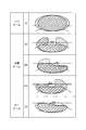
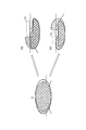
- FIG. 2 is a list of irradiation modes provided in the headlamp device.
- FIG. 3 is a flowchart (part 1) illustrating light distribution control processing executed by the control device.
- FIG. 4 is a flowchart (part 2) showing the light distribution control process executed by the control device.
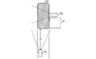
- FIG. 5 is a diagram illustrating an example of a region where brightness is measured when the vehicle front is not curved.
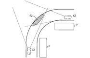
- FIG. 6 is a diagram illustrating an example of a region in which brightness is measured when the front of the vehicle is curved but no guardrail is present.
- FIG. 1 is a block diagram showing the configuration of the control system of this embodiment.
- FIG. 2 is a list of irradiation modes provided in the headlamp device.
- FIG. 3 is a flowchart (part 1) illustrating light distribution control processing executed by the control device.
- FIG. 4 is a flowchart (part 2) showing the light distribution control process executed by
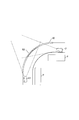
- FIG. 7 is a diagram illustrating an example of a region in which brightness is measured when the front of the vehicle is curved and a guardrail is present.
- FIG. 8 is a diagram illustrating an irradiation mode switching mode according to the appearance prediction result of the preceding vehicle.
- FIG. 9 is a diagram illustrating an irradiation mode switching mode according to the appearance prediction result of the preceding vehicle.
- a control system 1 of the present embodiment shown in FIG. 1 is a system that is mounted on a vehicle (four-wheeled vehicle or the like) K1 and controls the irradiation of light from a headlamp device 10 installed at the front end of the vehicle. is there.
- the control system 1 includes a headlamp device 10, an input device 20, a camera 30, a radar device 40, a luminance sensor 50, and a control device 60.
- the headlamp device 10 illuminates the front of the vehicle brightly in order to ensure the driver's view of the front of the vehicle.
- the headlamp device 10 is controlled to be turned on and off by the control device 60, and further switches the light irradiation direction (in other words, the light irradiation range).
- the headlamp device 10 has a plurality of irradiation modes with different light irradiation directions.
- the plurality of irradiation modes include an intermediate beam mode in addition to the high beam mode and the low beam mode.
- the high beam mode is an irradiation mode in which light is irradiated far away.
- the light irradiation direction in the high beam mode has a high elevation angle.
- a distant road area is brightly illuminated by a high elevation angle.
- the high beam mode strong light is likely to be irradiated to the passenger of the front vehicle K2 due to light irradiation at a high elevation angle, and it is easy to produce a dazzling result.
- the high beam mode is not used in an area with a high traffic volume (such as an urban area), but is used in an area with a low traffic volume (such as a mountainous area or an expressway).
- this high beam mode is also expressed as a first irradiation mode, and is indicated by using the symbol (I) in the drawings.
- a pair of hatching regions shown in the uppermost part of FIG. 2 represents a light irradiation range in the first irradiation mode.
- the headlamp device 10 includes lighting fixtures on the left and right sides of the front end portion of the vehicle, similarly to the known headlamp device.
- each of the pair of hatched areas displayed in a partially overlapping manner represents the light irradiation range by the left and right illuminators.
- the low beam mode is an irradiation mode in which light is irradiated to a road area in a short distance without irradiating light far away by irradiating light at a low elevation angle compared to the high beam mode. is there.
- the low beam mode is an irradiation mode that hardly causes dazzling to the passenger of the front vehicle K2 among the plurality of irradiation modes of the headlamp device 10, and is frequently used in an area where the traffic is heavy.
- this low beam mode is also expressed as a fifth irradiation mode, and is indicated by using a symbol (V) in the drawing.
- a pair of hatching regions shown in the lowermost stage in FIG. 2 represents the light irradiation range in the fifth irradiation mode.
- the intermediate beam mode is an irradiation mode in which features of a high beam mode and a low beam mode are mixed
- the headlamp device 10 of the present embodiment has three types of intermediate beam modes.
- these intermediate beam modes when the front of the host vehicle is divided into three sections, a left side, a center, and a right side, the features of the high beam mode and the low beam mode are mixed between these sections.
- One of the intermediate beam modes is an irradiation mode in which light is irradiated to the hatched area shown in the second stage of FIG.
- this irradiation mode is also expressed as a second irradiation mode, and is indicated by using a symbol (II) in the drawings.
- the second irradiation mode light is emitted far away by irradiating light at a high elevation angle in the left and right sections in front of the host vehicle as in the high beam mode.
- the central section similarly to the low beam mode, light is irradiated at a low elevation angle so that light is not irradiated far away.
- the second irradiation mode is used, for example, in an environment where no other vehicle exists in front of the left and right of the host vehicle K1.
- one of the intermediate beam modes is an irradiation mode in which light is irradiated to the hatched area shown in the third row of FIG.
- this irradiation mode is also expressed as a third irradiation mode, and is indicated by using a symbol (III) in the drawings.
- the third illumination mode light is emitted far away in the left compartment in front of the host vehicle as in the high beam mode, while light is emitted at a low elevation angle in the center and right compartment as in the low beam mode. Irradiate.
- the third irradiation mode is used, for example, in an environment where another vehicle exists on the right side in front of the host vehicle (for example, an area of 10 degrees or more on the right side in front of the host vehicle).
- one of the intermediate beam modes is an irradiation mode in which light is irradiated to the hatched area shown in the fourth row of FIG.
- this irradiation mode is also expressed as a fourth irradiation mode, and is indicated by using a symbol (IV) in the drawings.
- the fourth irradiation mode light is emitted at a high elevation angle in the right compartment in front of the host vehicle, as in the high beam mode, while in the middle and left compartments at a low elevation angle as in the low beam mode. Irradiate light.
- the fourth irradiation mode is used, for example, in an environment where another vehicle exists on the left side in front of the host vehicle (for example, an area of 10 degrees or more left in front of the host vehicle).
- the control device 60 switches the irradiation mode according to the driver's operation signal input from the input device 20 or according to the environment ahead of the host vehicle specified using the camera 30, the radar device 40, or the like. Do it.
- the input device 20 is attached in front of the driver's seat and receives a driver's operation related to turning on / off the headlamp device 10 and switching the irradiation mode.
- the camera 30 is a camera for photographing the front of the host vehicle.
- the camera 30 captures a wide range in front of the host vehicle including a region irradiated with light in the high beam mode.
- the camera 30 inputs a color video signal representing a captured image to the control device 60.
- the radar apparatus 40 emits a radar wave and receives the reflected wave by using an array antenna, so that the distance to the target that is the reflection source of the radar wave, the relative speed with respect to the target, and the target are detected. The direction of the target is measured, and data representing the measurement result is input to the control device 60.
- the radar device 40 is configured as, for example, a millimeter wave radar device.
- the brightness sensor 50 captures a wide range in front of the host vehicle corresponding to the capturing range of the camera 30, and detects the brightness of each point as the brightness of each point in the capturing range.
- the brightness sensor 50 inputs the detected brightness value at each point to the control device 60.
- control device 60 that receives a signal (data) input from the input device 20, the camera 30, the radar device 40, and the luminance sensor 50 includes a CPU 61, a ROM 63, and a RAM 65.
- the CPU 61 performs overall control of each part in the control system 1 by executing processing according to a program stored in the ROM 63.
- the ROM 63 stores the program, and the RAM 65 is used as a work area when the CPU 61 executes processing. Below, the process which CPU61 performs according to the said program is demonstrated using the expression which makes the control apparatus 60 an operation body.
- the control device 60 controls the headlamp device 10 according to the operation signal input from the input device 20 to realize turning on / off of the headlamp device 10 and switching of the irradiation mode.
- the driver gives an instruction to automatically switch the irradiation mode via the input device 20
- the light distribution control process shown in FIGS. 3 and 4 is repeatedly executed at regular intervals.
- the symbol S indicates a step executed by the control device 60, that is, the CPU 61.
- irradiation based on the positional relationship between the front object existing in the front visual field of the host vehicle K1 (that is, within the shooting range of the camera 30) and the host vehicle K1.
- the irradiation mode is switched based on the predicted result of the appearance of the forward vehicle K2 that does not yet exist in the forward visual field.
- the control device 60 When the light distribution control process is started, the control device 60 first uses the existing technology to select an irradiation mode suitable for the front environment as an irradiation mode to be set for the headlamp device 10 (S110). Specifically, an appropriate irradiation mode based on the positional relationship between the front object existing in the front visual field (within the shooting range of the camera 30) and the host vehicle K1 is selected as the irradiation mode to be set.
- the positional relationship between the preceding vehicle reflected on the camera 30 and the host vehicle K1 is specified, and an irradiation mode in which strong light is not irradiated to the preceding vehicle. Can be selected as the irradiation mode to be set.
- road attribute information or area attribute information corresponding to the current location is acquired from the navigation device 70 (see FIG. 1) having a road map installed in the host vehicle K1, and this information is taken into account.
- the irradiation mode to be set can be selected. For example, when the host vehicle K1 is in an urban area, the low beam mode is uniformly selected as the irradiation mode to be set, and only in other cases, the irradiation mode based on the positional relationship with the preceding vehicle is selected. For example, a selection is made.
- the control device 60 determines whether or not the selected irradiation mode of the setting target is the low beam mode (S115). If it is determined that the low beam mode is selected (Yes in S115), the process proceeds to S190.
- S190 it is determined whether or not the irradiation mode of the headlamp device 10 needs to be switched. If the currently set irradiation mode of the headlamp apparatus 10 is different from the irradiation mode to be set, it is determined that it is necessary to switch the irradiation mode (affirmative); otherwise, irradiation is performed. For example, it is determined that there is no need to switch modes (No).
- the process proceeds to S195, and the headlamp device 10 is controlled so as to operate in the setting target irradiation mode. That is, the irradiation mode of the headlamp device 10 is switched to the irradiation mode to be set. Thereafter, the light distribution control process is temporarily terminated. On the other hand, if a negative determination is made (No in S190), the control device 60 once ends the light distribution control process while maintaining the current irradiation mode of the headlamp device 10.
- control device 60 proceeds to S120.
- S120 it is determined whether or not the front of the host vehicle is an environment where it is difficult to predict the appearance of the forward vehicle K2.
- the vehicle is not captured by detecting an area illuminated by the headlight device of the vehicle that is not reflected in the camera 30 by the processing after S130. It detects before appearing in 30, and predicts that the vehicle will appear in the forward visual field. And when it appears that it appears, irradiation mode is switched so that strong light may not be irradiated with respect to the passenger
- control device 60 determines that the appearance prediction of the front vehicle K2 can be performed (No in S120), and proceeds to S130.
- the control device 60 determines whether or not a curved road area exists in the front view of the host vehicle K1. This determination can be realized, for example, by analyzing a video signal from the camera 30 and specifying a road shape in front of the host vehicle. In addition, the above determination can also be realized by acquiring information representing the road shape ahead of the host vehicle from the navigation device 70.
- the control device 60 proceeds to S135.
- S135 the brightness of the road surface in the road region R1 ahead of the host vehicle is measured.
- FIG. 5 shows an example of a region R1 in which the road surface brightness is measured in S135 as a hatched region.
- the luminance sensor 50 is caused to detect the luminance at each point in front of the host vehicle, and the luminance detection value at each point is acquired. Then, among the luminance detection values at each point, a group of luminance detection values at each point corresponding to the road surface of the region R1 specified from the video signal of the camera 30 and the measurement result of the radar device 40 is used as the brightness of the road surface of the region R1.
- the measured value M1 is extracted and stored.
- the road surface of the region R1 is divided into a plurality of blocks, the statistical value of the luminance detection value at each point included in this block is calculated for each block, and a group of statistical values for each block is It is stored as a measured value M1 for the brightness of the road surface of R1.
- the statistical value it is possible to calculate an average value, a median value, a total value, a maximum value, or the like of the luminance detection values at each point in the corresponding block.
- the region R1 can be defined as a region from this point to the road vanishing point in the photographed image of the camera 30, with reference to a point that is a predetermined distance D away from the host vehicle K1 along the road.
- the distance D is defined such that the region R1 is defined as a region where strong light is irradiated to the occupant of the front vehicle K2 depending on the high beam mode, but strong light is not irradiated to the occupant of the front vehicle K2 depending on the low beam mode. Can be determined.
- the control apparatus 60 will transfer to S160. On the other hand, if the control device 60 determines that there is a curved road area in the forward view (Yes in S130), the process proceeds to S140, and whether or not the guardrail 80 is installed along the curved road area. Determine whether.
- the guardrail 80 referred to here means an appendage of the road provided in a line along the road at the end of the road (roadway).
- the guard rail 80 referred to here includes a well-known guard rail in which a metal beam having a W-shaped cross section is attached to a column, a large wall-shaped guard rail standing up to a high position, a sound insulation wall, and the like. It is. In this specification, these are included and expressed as a guardrail.
- control device 60 proceeds to S145.
- S145 the brightness of the road surface in the curved road area R2 ahead of the host vehicle is measured.
- the luminance sensor 50 is made to detect the luminance of each point in front of the host vehicle. Then, among the detected luminance values at each point, a group of detected luminance values at each point corresponding to the road surface in the region R2 is extracted and stored as a measured value M2 for the brightness of the road surface in the region R2.
- a statistical value (average value, median value, total value, maximum value, etc.) of luminance detection values for each block is calculated, and these blocks are calculated.
- a group of statistical values for each can be stored as a measured value M2 regarding the brightness of the road surface in the region R2.
- the hatched area in FIG. 6 represents an example of an area R2 for measuring road brightness.
- the region R2 it is estimated that light from the headlamp device of the oncoming vehicle existing ahead of the curved road region in front of the host vehicle is irradiated on the road surface.
- a road area can be defined.
- the region R2 is determined so that the road surface is within the front visual field of the host vehicle K1, in other words, within the photographing range of the camera 30 and the luminance detection range by the luminance sensor 50.
- the area R2 in the forward visual field that is estimated to be irradiated with the light from the headlamp device of the oncoming vehicle is information on the road shape obtained from the navigation device 70, and the position and traveling direction of the host vehicle K1. Can be identified from the information about.
- a predetermined distance (or a distance from the point along the road)
- a road region up to a point at a predetermined angle along the curve) can be defined as a region R2.
- the control device 60 proceeds to S160.
- the control device 60 proceeds to S150 and measures the brightness of the side surface of the specific region R3 of the guardrail 80.
- the brightness sensor 50 is made to detect the brightness
- the statistical value (average value, median value, total value, maximum value, etc.) of the luminance detection value for each block is calculated, and these A group of statistical values for each block can be stored as a measured value M3 regarding the brightness of the side surface of the guardrail in the region R3.
- the hatched area in FIG. 7 represents an example of the area R3 for measuring the brightness of the side surface of the guardrail.
- the region R3 can be defined based on the same idea as the region R2. That is, as the region R3, the light from the headlamp device of the oncoming vehicle that exists ahead of the curved road region among the guard rails 80 provided along the curved road region in front of the host vehicle. It is possible to define a region that is estimated to be irradiated on the side surface.
- the region R3 can be defined as a region of the guardrail 80 provided along the region R2.
- the control device 60 proceeds to S160.
- control device 60 calculates the amount of change ⁇ from the previous measurement value M0 of the brightness measurement values M1, M2, and M3 calculated this time in any of S135, S145, and S150.
- the measurement values M1, M2, and M3 include the luminance detection values for each point.
- the amount of change ⁇ the amount of change ⁇ from the previous luminance detection value of the current luminance detection value at that point is obtained for each point. That is, the change amount ⁇ in this case consists of a group of change amounts ⁇ for each point. If the previous brightness detection value at the same point does not exist with the movement of the host vehicle K1 or the like, the amount of change ⁇ at that point may be regarded as zero.
- the measured values M1, M2, and M3 include statistical values for each block.
- the change amount ⁇ the change amount ⁇ from the previous statistical value of the current statistical value for the block is obtained for each block. That is, the change amount ⁇ in this case consists of a group of change amounts ⁇ for each block. If the previous statistical value of the same block does not exist with the movement of the host vehicle K1, etc., the change amount ⁇ of the block may be regarded as zero.
- the control device 60 proceeds to S170 and determines whether or not the calculated change amount ⁇ is equal to or greater than the threshold value TH.
- N for example, one
- the change amounts ⁇ among the change amounts ⁇ included in the change amount ⁇ or for each block is greater than or equal to the threshold value TH, and otherwise Can make a negative decision.
- control device 60 proceeds to S180, predicts that another vehicle will appear in the front view, and predicts its appearance area. Whether or not another vehicle appears in the front field of view can be predicted based on the determination in S170 in the measured values M1, M2, and M3, as shown in FIGS. This is because information on light emitted from the headlamp device of the forward vehicle K2 that does not appear in the forward visual field due to the influence of the curve is included.
- the broken lines shown in FIGS. 5, 6, and 7 schematically represent the irradiation ranges of light from the host vehicle K ⁇ b> 1 and the preceding vehicle K ⁇ b> 2.
- the measurement values M1, M2, and M3 change as the front vehicle K2 moves.
- the measurement values M1, M2, and M3 change more than a certain value, there is a high possibility that a vehicle having a strong light source is moving toward the regions R1, R2, and R3. .
- whether or not the vehicle appears in the front view is predicted by determining whether or not the change amount ⁇ is equal to or greater than the threshold value TH.
- a fixed value can be adopted as the threshold value TH.
- the fixed value a value that provides a certain prediction accuracy may be determined, and this can be obtained by a test or the like.
- the measurement values M1, M2, and M3 may include a luminance component that is not negligible due to light irradiation from the headlight device 10 of the host vehicle K1.
- the change amount ⁇ may be greater than or equal to the threshold value TH using the threshold value TH as a fixed value. Due to the increase, there is a possibility of erroneously predicting that the preceding vehicle K2 appears. That is, when the threshold value TH is a fixed value, high prediction accuracy may not be obtained.
- the threshold value TH can be set to a value (C + A) obtained by adding the increment A of the change amount ⁇ (change amount ⁇ ) due to light irradiation from the headlamp device 10 of the host vehicle K1 to the standard value C.
- This value A can be obtained by calculation from the traveling speed of the host vehicle K1 and the positional relationship between the host vehicle K1 and the regions R1, R2, and R3 corresponding to the measured values M1, M2, and M3. For example, when the host vehicle K1 is stopped, the threshold TH can be set by regarding the increase A as zero.
- the threshold value TH can be a uniform value between points (or blocks), but an individual value may be used for each point (or block). Further, the standard value C can be determined in consideration of the material of the road surface and the side surface of the guard rail, the legal speed of the road, and the like.
- an appearance area is predicted.
- the appearance area can be predicted as follows, depending on the presence or absence of a curve and the direction of the curve, for example. For example, in the case where an affirmative determination is made in S130 and the road area in the forward view is curved to the right, as shown in FIG. It can be predicted as an appearance area G1 in which K2 appears.
- the center in front of the host vehicle and the upper section on the left side can be predicted as the appearance area G2 in which the forward vehicle K2 appears.
- the upper left side, the center, and the right upper section of the host vehicle can be predicted as the appearance area G3 in which the forward vehicle K2 appears.
- the control device 60 proceeds to S185, and sets the irradiation mode in which the predicted appearance areas G1, G2, and G3 are dark as the setting target irradiation mode. Select again. That is, the setting target irradiation mode selected in S110 is changed to an irradiation mode that does not irradiate the appearance areas G1, G2, and G3.
- the irradiation mode selected in S110 is not the low beam mode. Therefore, according to the irradiation mode selected in S110, light is irradiated at a high angle in at least one of the left, center, and right sections.
- the section irradiated with light at a high angle according to the irradiation mode selected in S110 includes the appearance areas G1, G2, and G3, the section is irradiated with light at a low elevation angle.
- the irradiation mode is changed.
- the irradiation mode is selected so that light is irradiated at a high angle for the sections that are selected to be irradiated at a high angle by the selection of the irradiation mode in S110 and that do not correspond to the appearance areas G1, G2, and G3. Can be selected.
- control device 60 proceeds to S190. Then, whether or not it is necessary to switch the irradiation mode of the headlamp device 10 by comparing the currently set irradiation mode of the headlamp device 10 with the irradiation mode of the setting target selected in S185. Judging.
- the process proceeds to S195, and the headlamp device 10 is operated so that the headlamp device 10 operates in the setting target irradiation mode selected in S185. To control. Thereafter, the light distribution control process is temporarily terminated. The control device 60 repeatedly executes such a light distribution control process.
- the vehicle K2 ahead from the tip of the road area curved to the right side when (oncoming vehicle) appears, as shown in FIG. 8, the irradiation mode of the headlamp device 10 is the area G1 where the front vehicle K2 appears from the first irradiation mode before the appearance. Is switched to the third irradiation mode in which no light is irradiated (S195).
- the arrow from symbol (I) to symbol (III) in FIG. 8 illustrates switching from the first irradiation mode to the third irradiation mode.
- the irradiation mode of the headlamp device 10 is determined by the appearance prediction before the appearance. Is switched to the fourth irradiation mode in which light is not irradiated to the area G2 where the vehicle appears.
- the arrow from symbol (I) to symbol (IV) in FIG. 8 illustrates switching from the first irradiation mode to the fourth irradiation mode.
- the irradiation mode of the headlamp device 10 is changed from the first irradiation mode to the fifth irradiation mode (low beam) that does not irradiate the area G3 in which the preceding vehicle K2 appears. Mode) (S195).
- the arrow from symbol (I) to symbol (V) in FIG. 9 illustrates switching from the first irradiation mode to the fifth irradiation mode.
- the control system 1 of the present embodiment even when the front of the host vehicle is in an environment where the line of sight is poor, the irradiation of the light from the headlamp device 10 is appropriately controlled to dazzle the vehicle occupants of other vehicles ( (Glare) can be suppressed.
- the result is that the vehicle occupant who has already appeared is dazzled during the period until the switching is completed. It was.
- the irradiation mode can be switched more quickly than before, and the irradiation mode can be switched to an appropriate irradiation mode before the vehicle appears. It is possible to suppress dazzling for the passenger of the front vehicle K2 that appears.
- the present invention is not limited to the above-described embodiments, and can take various forms.
- the measurement values M1, M2, and M3 in the above-described embodiment are configured by a group of luminance detection values for each point or statistical values for each block, but the measurement values M1, M2, and M3 correspond to the corresponding regions R1, R2.
- R3 may be one statistical value corresponding to the luminance detection value group (for example, the average value of the luminance detection values). In this case, even if the regions R1, R2, and R3 corresponding to the previous measurement value M0 are shifted from the regions R1, R2, and R3 corresponding to the current measurement values M1, M2, and M3, they are the same region. Assuming that there is, a change amount ⁇ is obtained.
- luminance of each point ahead of the own vehicle was detected using the brightness sensor 50
- luminance of each point ahead of the own vehicle can also be specified from the picked-up image of the camera 30. It is. Therefore, in S135, S145, and S150, the luminance at each point may be detected by analyzing the captured image of the camera 30.
- the light distribution control process shown in FIGS. 3 and 4 is a process for correcting the irradiation mode instructed by the driver to an irradiation mode that does not dazzle the occupant of the front vehicle K2 appearing in the front view. It may be configured.
- the process of S110 can be configured as a process of selecting the irradiation mode instructed by the driver via the input device 20 as the irradiation mode to be set.
- the functions realized by the processing of S160, S170, and S180 executed by the control device 60 correspond to an example of the function realized by the prediction unit, and are realized by the processing of S185, S190, and S195 executed by the control device 60.
- the function to be performed corresponds to an example of a function realized by the control unit.
- the function realized by the processing of S130 and S140 executed by the control device 60 corresponds to an example of the function realized by the curve determination unit.
- SYMBOLS 1 Control system, 10 ... Headlamp device, 20 ... Input device, 30 ... Camera, 40 ... Radar device, 50 ... Luminance sensor, 60 ... Control device, 61 ... CPU, 63 ... ROM, 65 ... RAM, 70 ... Navigation device, 80 ... guard rail, G1, G2, G3 ... appearance area, K1 ... own vehicle, K2 ... front vehicle, P ... shield, R1, R2, R3 ... area.
Landscapes
- Engineering & Computer Science (AREA)
- Mechanical Engineering (AREA)
- Lighting Device Outwards From Vehicle And Optical Signal (AREA)
Abstract
前照灯装置を制御する制御装置は、輝度センサを用いて、自車両前方の明るさを計測する処理を繰り返し実行する。例えば、自車両前方にカーブしている道路領域が存在している場合には、この道路領域における特定領域(前方車両の前照灯装置からの光が照射される領域)の路面又はガードレールの明るさを計測する。そして、明るさの計測値の前回計測値からの変化量Δを算出し(S160)、変化量Δが閾値TH以上であるときには(S170でYes)、自車両の前方視野に未だ現れていない車両が新たに出現すると予測して(S180)、この出現エリアを暗くするように、前照灯装置からの光の照射モードを切り替える(S185,S190,S195)。
Description
本発明は、車両の前照灯の光照射を制御する制御装置及びその制御装置を備えた前照灯システムに関する。
従来、車両に搭載された前照灯装置が照射する光の照射状態を制御する制御装置が知られている。この照射制御は様々な情報に基づいてなされる。
例えば、対向車の接近状態や周囲の明るさに基づき、前照灯装置の光の照射状態を制御する制御装置が知られている。また、カメラによる撮影画像から道路形状を認識し、認識した道路形状から対向車が存在し得る領域を推定し、その推定結果に応じて前記照射制御を行う制御装置も知られている(例えば、特許文献1参照)。この制御装置によれば、上記推定した領域に対向車が近づいたことを、ミリ波レーダ装置を用いて検知し、検知したことを条件に、光の照射を制御して、対応する領域に光が照射されないようにする。
例えば、対向車の接近状態や周囲の明るさに基づき、前照灯装置の光の照射状態を制御する制御装置が知られている。また、カメラによる撮影画像から道路形状を認識し、認識した道路形状から対向車が存在し得る領域を推定し、その推定結果に応じて前記照射制御を行う制御装置も知られている(例えば、特許文献1参照)。この制御装置によれば、上記推定した領域に対向車が近づいたことを、ミリ波レーダ装置を用いて検知し、検知したことを条件に、光の照射を制御して、対応する領域に光が照射されないようにする。
上述したように従来装置によれば、何れの例の場合でも、前方車両を検知したときに、前照灯装置からの光の照射を制御し、前方車両に対し強い光を照射しないようにする。
しかしながら、進路前方の見通しが悪い環境では、迅速に前方車両を検知することができない。従って、従来装置によれば、見通しの悪い環境では、前方車両の検知に基づいた上記制御が完了するまでの期間に、前方車両の車両乗員に眩惑(グレア)を与えてしまうといった欠点があった。
しかしながら、進路前方の見通しが悪い環境では、迅速に前方車両を検知することができない。従って、従来装置によれば、見通しの悪い環境では、前方車両の検知に基づいた上記制御が完了するまでの期間に、前方車両の車両乗員に眩惑(グレア)を与えてしまうといった欠点があった。
本発明は、こうした問題に鑑みなされたものであり、見通しの悪い環境下でも、前照灯装置からの光の照射をよりタイミング良く制御することで、前方に現れる他の車両の乗員に眩惑を与えてしまうことを防止又は低減するようにすることを目的とする。
本開示に係る前照灯制御装置は、車両に搭載された前照灯装置を制御する装置であって、計測手段と、予測手段と、制御手段と、を備える。計測手段は、車両前方の明るさを計測する。予測手段は、計測手段が計測した車両前方における特定領域の明るさの変化に基づき、車両前方に他の車両が出現するか否かを予測する。制御手段は、予測手段によって他の車両が出現すると予測された場合に、他の車両が出現するエリアを暗くするように前照灯装置からの光の照射を制御する。
車両の前照灯装置が点灯している環境では、周辺に存在する他の車両においても前照灯装置が点灯していると考えられる。従って、自車両と接近するような関係で移動する他の車両に関しては、他の車両の出現に先立って、自車両前方に、他の車両の前照灯装置による光の照射領域が現れる。この前照灯制御装置は、自車両前方の明るさを計測することによって、このような現象を観測し、他の車両の出現を予測する。
本開示によれば、前方車両が出現する前に、その出現を予測して前照灯装置からの光の照射を制御することができる。従って、前方車両を検知したことを条件に、前照灯装置からの光の照射を制御する従来装置よりも、自車両からの光の照射によって前方車両の車両乗員に眩惑を与えてしまう可能性を抑えることができる。よって、従来よりも優れた前照灯制御装置を構成することができる。
具体的に、この前照灯制御装置は、車両前方に、カーブしている道路領域が存在する環境において、カーブしている道路領域周辺における特定領域の明るさの変化に基づき、他の車両が出現するか否かを予測する構成にすることができる。
即ち、前照灯制御装置は、車両前方に、カーブしている道路領域が存在するか否かを判定するカーブ判定手段を備えた構成にすることができる。そして、予測手段は、カーブしている道路領域が存在すると判定された場合に、カーブしている道路領域周辺の特定領域において計測手段が計測した明るさの変化に基づき、他の車両が出現するか否かを予測する構成にすることができる。
このような前照灯制御装置によれば、車両前方の道路がカーブしていることによって、他の車両が出現するまでに自車両と他の車両とが接近してしまう場合でも、適切に前照灯装置からの光の照射を制御し、他の車両の乗員に眩惑を与えてしまうのを抑えることができる。
添付図面において:
図1は、本実施例の制御システムの構成を表すブロック図である。
図2は、前照灯装置が備える照射モードのリストである。
図3は、制御装置が実行する配光制御処理を表すフローチャート(その1)である。
図4は、制御装置が実行する配光制御処理を表すフローチャート(その2)である。
図5は、車両前方がカーブしていないときに、明るさを計測する領域の一例を示す図である。
図6は、車両前方がカーブしているがガードレールが存在しないときに、明るさを計測する領域の一例を示す図である。
図7は、車両前方がカーブしており且つガードレールが存在するときに、明るさを計測する領域の一例を示す図である。
図8は、前方車両の出現予測結果に従う照射モードの切替態様を説明した図である。
図9は、前方車両の出現予測結果に従う照射モードの切替態様を説明した図である。
以下に本発明の実施例について、図面と共に説明する。
図1に示す本実施例の制御システム1は、車両(四輪自動車等)K1に搭載されて、車両の前方端部に設置された前照灯装置10からの光の照射を制御するシステムである。この制御システム1は、前照灯装置10と、入力装置20と、カメラ30と、レーダ装置40と、輝度センサ50と、制御装置60と、を備える。
図1に示す本実施例の制御システム1は、車両(四輪自動車等)K1に搭載されて、車両の前方端部に設置された前照灯装置10からの光の照射を制御するシステムである。この制御システム1は、前照灯装置10と、入力装置20と、カメラ30と、レーダ装置40と、輝度センサ50と、制御装置60と、を備える。
前照灯装置10は、周知のように車両前方に対する運転者の視界を確保するために、車両前方を明るく照らすものである。この前照灯装置10は、制御装置60に制御されて、点灯及び消灯し、更には光の照射方向(換言すれば光の照射範囲)を切り替える。
具体的に、この前照灯装置10は、光の照射方向が異なる複数の照射モードを有する。複数の照射モードには、ハイビームモード及びロービームモードの他、中間ビームモードが含まれる。
ハイビームモードは、周知のように、遠方に光を照射する照射モードである。ハイビームモードによる光の照射方向は、高い仰角を有する。ハイビームモードによれば、高い仰角によって、遠方の道路領域までが明るく照らされる。
但し、ハイビームモードによれば、高い仰角による光の照射により前方車両K2の乗員に強い光が照射されやすく、眩惑を与える結果を生み易い。このため、一般的に、ハイビームモードは、交通量の多い地域(市街地等)では使用されず、交通量の少ない地域(山間部や高速道路等)で使用される。
以下では、このハイビームモードを、第一の照射モードとも表現し、図面においては記号(I)を用いて指し示す。図2の最上段に示す一対のハッチング領域は、第一の照射モードによる光の照射範囲を表す。前照灯装置10は、周知の前照灯装置と同様、車両前方端部の左右の夫々に照明具を備える。図2において、一部重ねて表示される一対のハッチング領域の夫々は、左右の照明具の夫々による光の照射範囲を表す。
また、ロービームモードは、周知のように、ハイビームモードと比較して低い仰角で光を照射することによって、遠方に光を照射せずに近距離の道路領域に対して光を照射する照射モードである。
ロービームモードは、前照灯装置10が有する複数の照射モードの内、最も前方車両K2の乗員に対して眩惑を与えにくい照射モードであり、交通量の多い地域で、高頻度に使用される。以下では、このロービームモードを、第五の照射モードとも表現し、図面においては記号(V)を用いて指し示す。図2の最下段に示す一対のハッチング領域は、第五の照射モードによる光の照射範囲を表す。
また、中間ビームモードは、ハイビームモード及びロービームモードの特徴が混在する照射モードであり、本実施例の前照灯装置10は、三種類の中間ビームモードを有する。これらの中間ビームモードの夫々は、自車両前方を左側、中央、右側と三区画に分割した場合において、これらの区画間にハイビームモード及びロービームモードの特徴が混在する。
中間ビームモードの一つは、図2の第二段目に示すハッチング領域に、光を照射する照射モードである。以下では、この照射モードを、第二の照射モードとも表現し、図面においては、記号(II)を用いて指し示す。
図2からも理解できるように、第二の照射モードによれば、自車両前方の左側及び右側の区画において、ハイビームモードと同様に、高い仰角で光を照射することにより、遠方まで光を照射する一方、中央の区画において、ロービームモードと同様に、低い仰角で光を照射して、遠方まで光が照射されないようにする。第二の照射モードは、例えば、自車両K1の左右前方に他の車両が存在しない環境等で使用される。
また、中間ビームモードの一つは、図2の三段目に示すハッチング領域に、光を照射する照射モードである。以下では、この照射モードを、第三の照射モードとも表現し、図面においては、記号(III)を用いて指し示す。
第三の照射モードによれば、自車両前方の左側の区画において、ハイビームモードと同様に、遠方まで光を照射する一方、中央及び右側の区画において、ロービームモードと同様に、低い仰角で光を照射する。第三の照射モードは、例えば、自車両前方の右側(例えば、自車両前方の右10度以上の領域)に、他の車両が存在する環境等で使用される。
この他、中間ビームモードの一つは、図2の四段目に示すハッチング領域に、光を照射する照射モードである。以下では、この照射モードを、第四の照射モードとも表現し、図面においては、記号(IV)を用いて指し示す。
第四の照射モードによれば、自車両前方の右側の区画において、ハイビームモードと同様に、高い仰角で光を照射する一方、中央及び左側の区画においては、ロービームモードと同様に、低い仰角で光を照射する。第四の照射モードは、例えば、自車両前方の左側(例えば、自車両前方の左10度以上の領域)に、他の車両が存在する環境等で使用される。
制御装置60は、このような照射モードの切替を、入力装置20から入力される運転者の操作信号に従って、又は、カメラ30やレーダ装置40等を用いて特定される自車両前方の環境に応じて行う。入力装置20は、周知のように、運転席前方に取り付けられて、前照灯装置10の点灯/消灯、及び、照射モードの切替に関する運転者の操作を受け付けるものである。
また、カメラ30は、自車両前方を撮影するカメラである。このカメラ30は、ハイビームモード時に光が照射される領域を含む、自車両前方の広い範囲を撮影する。このカメラ30は、撮影画像を表すカラーの映像信号を、制御装置60に入力する。
この他、レーダ装置40は、レーダ波を発射し、その反射波を、アレーアンテナを用いて受信することにより、レーダ波の反射元である物標までの距離、物標との相対速度及び物標の方位を計測し、その計測結果を表すデータを、制御装置60に入力するものである。レーダ装置40は、例えば、ミリ波レーダ装置として構成される。
また、輝度センサ50は、カメラ30の撮影範囲に対応する自車両前方の広い範囲を撮影し、撮影範囲内の各地点の明るさとして、各地点の輝度を検出するものである。輝度センサ50は、各地点の輝度の検出値を制御装置60に入力する。
一方、入力装置20、カメラ30、レーダ装置40、及び、輝度センサ50からの信号(データ)入力を受ける制御装置60は、CPU61と、ROM63と、RAM65と、を備える。
CPU61は、ROM63が記憶するプログラムに従う処理を実行することにより、制御システム1内の各部を統括制御する。ROM63は、上記プログラムを記憶し、RAM65は、CPU61による処理実行時に作業領域として使用される。以下では、CPU61が上記プログラムに従って実行する処理を、制御装置60を動作主体とする表現を用いて説明する。
制御装置60は、上述したように、入力装置20から入力される操作信号に従って、前照灯装置10を制御し、前照灯装置10の点灯/消灯、及び、照射モードの切替を実現する。一方、入力装置20を介して運転者から照射モードを自動で切り替えるように指示された場合には、図3及び図4に示す配光制御処理を一定時間毎に繰り返し実行する。なお、これらの処理の説明において、符号Sは、制御装置60、すなわちCPU61により実行されるステップを示す。
この配光制御処理では、カメラ30から得られる映像信号に基づき、自車両K1の前方視野内(即ちカメラ30の撮影範囲内)に存在する前方物体と自車両K1との位置関係に基づいた照射モードの切替を行う他、未だ前方視野内には存在しない前方車両K2の前方視野内への出現予測結果に基づいた照射モードの切替を行う。
上記配光制御処理を開始すると、制御装置60は、まず既存技術を用いて、前方環境に適切な照射モードを、前照灯装置10への設定対象の照射モードとして選択する(S110)。具体的には、前方視野内(カメラ30の撮影範囲内)に存在する前方物体と自車両K1との位置関係に基づいた適切な照射モードを上記設定対象の照射モードとして選択する。
S110では、カメラ30からの映像信号及びレーダ装置40の計測結果に基づき、カメラ30に映る前方車両と自車両K1との位置関係を特定し、この前方車両に強い光が照射されないような照射モードを上記設定対象の照射モードとして選択することができる。
この他、S110では、自車両K1に設置された道路地図を有するナビゲーション装置70(図1参照)から現在地に対応する道路属性又は地域属性の情報を、車内ネットワークを通じて取得し、この情報を加味して、上記設定対象の照射モードを選択することもできる。例えば、自車両K1が市街地にいる場合には、上記設定対象の照射モードとして、一律にロービームモードを選択し、それ以外の場合に限って、上記前方車両との位置関係に基づいた照射モードの選択を行うといった具合である。
S110での処理を終えると、制御装置60は、選択した上記設定対象の照射モードが、ロービームモードであるか否かを判断する(S115)。そして、ロービームモードであると判断すると(S115でYes)、S190に移行する。
S190では、前照灯装置10の照射モードを切り替える必要があるか否かを判断する。現在設定されている前照灯装置10の照射モードと、上記設定対象の照射モードとが異なる場合には、照射モードを切り替える必要があると(肯定)判断し、それ以外の場合には、照射モードを切り替える必要がないと(否定)判断するといった具合である。
そして、肯定判断すると(S190でYes)、S195に移行して、上記設定対象の照射モードで動作するように前照灯装置10を制御する。即ち、前照灯装置10の照射モードを、上記設定対象の照射モードに切り替える。その後、配光制御処理を一旦終了する。これに対し、否定判断すると(S190でNo)、制御装置60は、前照灯装置10の現照射モードを維持したまま、当該配光制御処理を一旦終了する。
この他、S115において、上記設定対象の照射モードがロービームモードでないと判断すると(S115でNo)、制御装置60は、S120に移行する。S120では、自車両前方が、前方車両K2の出現予測を行うのが困難な環境であるか否かを判断する。
詳しくは後述するが、本実施例によれば、S130以降の処理によって、カメラ30に映っていない車両を、その車両の前照灯装置により照らされた領域を検知することにより、その車両がカメラ30に映る前に検知し、その車両が前方視野内に出現することを予測する。そして、出現することが予測される場合には、この車両の乗員に対して強い光が照射されないように、照射モードを切り替える。
但し、前方視野が先行車により一部遮られている場合や、自車両前方や明るすぎて、出現を予測する対象の車両による光の照射領域を高精度に検知できない場合には、前方車両K2の出現予測を十分な精度で行うことができない。その結果として、予測結果に基づいた適切な照射モードの切替を行うことができない。
そこで、S120では、自車両前方がS130以降で前方車両K2の出現予測を許容できる精度で行うことのできる予め定められた環境にない場合、前方車両K2の出現予測を行うのが困難な環境であると判断して(S120でYes)、S190に移行する。その後、S110で選択した上記設定対象の照射モードで前照灯装置10が動作するように、前照灯装置10を制御する。
一方、自車両前方が上記予め定められた環境にある場合、制御装置60は、前方車両K2の出現予測を行うことが可能であると判断して(S120でNo)、S130に移行する。
S130に移行すると、制御装置60は、自車両K1の前方視野内に、カーブしている道路領域が存在するか否かを判断する。この判断は、例えば、カメラ30からの映像信号を解析し、自車両前方の道路形状を特定することによって実現することができる。この他、上記判断は、ナビゲーション装置70から自車両前方の道路形状を表す情報を取得することによっても実現することができる。
S130において、カーブしている道路領域が存在しないと判断すると、制御装置60は、S135に移行する。そして、S135では、自車両前方の道路領域R1における路面の明るさを計測する。図5には、S135で路面の明るさを計測する領域R1の例をハッチング領域で示す。
例えば、S135では、輝度センサ50に自車両前方における各地点の輝度を検出させて、これら各地点の輝度検出値を取得する。そして、各地点の輝度検出値の内、カメラ30の映像信号及びレーダ装置40の計測結果から特定される領域R1の路面に該当する各地点の輝度検出値の一群を、領域R1の路面の明るさについての計測値M1として抽出し記憶する。
別例としては、領域R1の路面を、複数ブロックに分割し、ブロック毎に、このブロックに含まれる各地点の輝度検出値の統計値を算出し、このブロック毎の統計値の一群を、領域R1の路面の明るさについての計測値M1として記憶する。統計値としては、対応するブロックにおける各地点の輝度検出値の平均値、中央値、合計値、又は、最大値等を算出することが可能である。
この他、領域R1は、道路に沿って自車両K1から所定距離D離れた地点を基準に、この地点からカメラ30の撮影画像における道路消失点までの領域に定めることができる。距離Dは、領域R1が、ハイビームモードによっては、強い光が前方車両K2の乗員に照射されるが、ロービームモードによっては、強い光が前方車両K2の乗員に照射されない領域として定義されるように、定めることができる。
S135において領域R1の路面の明るさについての計測値M1を算出すると、制御装置60は、S160に移行する。
一方、制御装置60は、前方視野にカーブしている道路領域が存在すると判断すると(S130でYes)、S140に移行し、カーブしている道路領域に沿って、ガードレール80が設置されているか否かを判断する。
一方、制御装置60は、前方視野にカーブしている道路領域が存在すると判断すると(S130でYes)、S140に移行し、カーブしている道路領域に沿って、ガードレール80が設置されているか否かを判断する。
但し、ここで言うガードレール80は、道路(車道)の端において、道路に沿って一条に設けられた道路の付属物を意味する。即ち、ここで言うガードレール80には、W型の断面を有した金属製ビームを支柱に取り付けたよく知られるガードレールの他、高い位置まで立設された壁状の大型ガードレールや、遮音壁等も含まれる。本願明細書では、これらを含めてガードレールと表現する。
S140において、ガードレール80が設置されていないと判断すると、制御装置60は、S145に移行する。そして、S145では、自車両前方のカーブしている道路領域R2における路面の明るさを計測する。
例えば、S145では、S135と同様に、輝度センサ50に自車両前方における各地点の輝度を検出させる。そして、これら各地点の輝度検出値の内、領域R2の路面に該当する各地点の輝度検出値の一群を、領域R2の路面の明るさについての計測値M2として抽出し記憶する。
別例としては、領域R2の路面を、複数ブロックに分割したときの、ブロック毎の輝度検出値の統計値(平均値、中央値、合計値、又は、最大値等)を算出し、これらブロック毎の統計値の一群を、領域R2の路面の明るさについての計測値M2として記憶することができる。
図6におけるハッチング領域は、路面の明るさを計測する領域R2の例を表す。領域R2としては、自車両前方のカーブしている道路領域の内、当該カーブしている道路領域の先に存在する対向車の前照灯装置からの光が路面に照射されると推定される道路領域を定めることができる。但し、領域R2については、その路面が自車両K1の前方視野内、換言すれば、カメラ30の撮影範囲内及び輝度センサ50による輝度の検出範囲内に収まるように定める。
上記対向車の前照灯装置からの光が路面に照射されると推定される前方視野内の領域R2は、ナビゲーション装置70から得られる道路形状に関する情報、並びに、自車両K1の位置及び進行方向に関する情報から特定することができる。
このような道路形状に関する情報が得られない環境においては、例えば、カーブの終点、又は、カーブしている道路領域が前方視野から外れる地点を基準に、その地点から道路に沿って所定距離(又はカーブに沿う所定角度)手前の地点までの道路領域を、領域R2に定めることができる。
このようにして、領域R2における路面の明るさについての計測値M2を算出すると、制御装置60は、S160に移行する。
この他、制御装置60は、S140においてガードレール80が設置されていると判断すると、S150に移行し、ガードレール80の特定領域R3における側面の明るさを計測する。
この他、制御装置60は、S140においてガードレール80が設置されていると判断すると、S150に移行し、ガードレール80の特定領域R3における側面の明るさを計測する。
例えば、S150では、S135,S145での処理と同様に、輝度センサ50に自車両前方における各地点の輝度を検出させる。そして、これら各地点の輝度検出値の内、領域R3のガードレール側面に該当する各地点の輝度検出値の一群を、領域R3のガードレール側面の明るさについての計測値M3として抽出し記憶する。
別例としては、領域R3のガードレール側面を、複数ブロックに分割したときの、ブロック毎の輝度検出値の統計値(平均値、中央値、合計値、又は、最大値等)を算出し、これらブロック毎の統計値の一群を、領域R3のガードレール側面の明るさについての計測値M3として記憶することができる。
図7におけるハッチング領域は、ガードレール側面の明るさを計測する領域R3の例を表す。領域R3は、領域R2と同様の思想で定めることができる。即ち、領域R3としては、自車両前方のカーブしている道路領域に沿って設けられたガードレール80の内、当該カーブしている道路領域の先に存在する対向車の前照灯装置からの光が側面に照射されると推定される領域を定めることができる。
例えば、領域R3は、領域R2に沿って設けられたガードレール80の領域に定義することができる。このようにして、領域R3におけるガードレール側面の明るさについての計測値M3を算出すると、制御装置60は、S160に移行する。
S160に移行すると、制御装置60は、S135,S145,S150のいずれかにおいて今回算出した明るさの計測値M1,M2,M3の前回計測値M0からの変化量Δを算出する。
但し、今回、S135で計測値M1を算出した場合には、前回のS135で算出した計測値M1を前回計測値M0として用いて、変化量Δ=M1-M0を算出する。即ち、今回計測値Mi(i=1,2,3)を算出した場合には、前回の同じステップで算出した計測値Mi(i=1,2,3)を前回計測値M0として用いて、変化量Δ=Mi-M0を算出する。
該当する前回計測値M0が存在しない場合(前回の配光制御処理において異なるステップで異なる種類の計測値M1,M2,M3を算出している場合等)には、前回計測値M0が今回の計測値Miと同じであるとみなして、変化量Δ=0を算出する。
付言すると、上述した例によれば、計測値M1,M2,M3には、地点毎の輝度検出値が含まれる。この場合、変化量Δとしては、地点毎に、その地点での今回の輝度検出値の、前回の輝度検出値からの変化量δを求める。即ち、この場合の変化量Δは、地点毎の変化量δの一群からなる。自車両K1の移動等に伴って同一地点の前回輝度検出値が存在しない場合には、その地点の変化量δをゼロとみなせばよい。
また、上述した別例によれば、計測値M1,M2,M3には、ブロック毎の統計値が含まれる。この場合、変化量Δとしては、ブロック毎に、そのブロックに関する今回の統計値の、前回の統計値からの変化量δを求める。即ち、この場合の変化量Δは、ブロック毎の変化量δの一群からなる。自車両K1の移動等に伴って同一ブロックの前回統計値が存在しない場合には、そのブロックの変化量δをゼロとみなせばよい。
このようにして変化量Δを算出すると、制御装置60は、S170に移行し、当該算出した変化量Δが閾値TH以上であるか否かを判断する。ここでは、変化量Δに含まれる地点毎又はブロック毎の変化量δの内のN個(例えば一つ)以上の変化量δが閾値TH以上であるとき、肯定判断し、それ以外の場合には、否定判断することができる。
そして、肯定判断すると(S170でYes)、制御装置60は、S180に移行し、前方視野に他の車両が出現すると予測すると共に、その出現エリアを予測する。
S170での判断によって、前方視野に他の車両が出現するか否かを予測できるのは、計測値M1,M2,M3には、図5,6,7に示すように、遮蔽物Pや道路カーブの影響によって前方視野に現れていない前方車両K2の前照灯装置から照射される光の情報が含まれるためである。図5,6,7に示す破線は、自車両K1及び前方車両K2からの光の照射範囲を概略的に表したものである。
S170での判断によって、前方視野に他の車両が出現するか否かを予測できるのは、計測値M1,M2,M3には、図5,6,7に示すように、遮蔽物Pや道路カーブの影響によって前方視野に現れていない前方車両K2の前照灯装置から照射される光の情報が含まれるためである。図5,6,7に示す破線は、自車両K1及び前方車両K2からの光の照射範囲を概略的に表したものである。
領域R1,R2の路面や領域R3のガードレール側面に前方車両K2からの光が照射されている場合には、前方車両K2の移動に伴って、計測値M1,M2,M3が変化する。また、一般的な道路環境を考えると、計測値M1,M2,M3が一定以上変化する場合には、強い光源を有する車両が領域R1,R2,R3に向かって移動している可能性が高い。
そこで、本実施例では、変化量Δが閾値TH以上であるか否かの判断によって、前方視野に車両が出現するか否かを予測する。計測値M1,M2,M3において、自車両K1の前照灯装置10からの光の照射による輝度成分の割合が小さい場合、閾値THとしては、例えば、固定値を採用することができる。固定値としては、一定の予測精度が得られる値を定めればよく、これは試験等により求めることができる。
但し、計測値M1,M2,M3には、自車両K1の前照灯装置10からの光の照射による輝度成分が無視できない程度に含まれる場合も考えられる。この場合には、固定値としての閾値THを用いて、変化量Δが閾値TH以上であるか否かの判断を行っても、自車両K1の移動に伴う変化量Δ(変化量δ)の増加によって、前方車両K2が出現すると誤って予測してしまう可能性がある。即ち、閾値THを固定値とした場合には、高い予測精度が得られない可能性がある。
そこで、閾値THは、標準値Cに、自車両K1の前照灯装置10からの光の照射による変化量Δ(変化量δ)の増加分Aを加算した値(C+A)に定めることができる。この値Aは、自車両K1の走行速度や、自車両K1と計測値M1,M2,M3に対応する領域R1,R2,R3との位置関係から演算により求めることが可能である。例えば、自車両K1が停止している状態では、この増加分Aをゼロとみなして、閾値THを設定することができる。
尚、閾値THは、地点(又はブロック)間で一律の値を用いることができるが、地点(又はブロック)毎に個別の値を用いてもよい。また、標準値Cは、路面やガードレール側面の材質、道路の法定速度等を加味して、定めることも可能である。
また、S180では、出現エリアを予測するが、この出現エリアは、カーブの有無及びカーブの向きによって、例えば、次のように予測することができる。
例えば、S130において肯定判断した場合であって、前方視野内の道路領域が右にカーブしている場合には、図8に示すように、自車両前方の中央及び右側の区画上部を、前方車両K2が出現する出現エリアG1として予測することができる。
例えば、S130において肯定判断した場合であって、前方視野内の道路領域が右にカーブしている場合には、図8に示すように、自車両前方の中央及び右側の区画上部を、前方車両K2が出現する出現エリアG1として予測することができる。
また、前方視野内の道路領域が左にカーブしている場合には、自車両前方の中央及び左側の区画上部を、前方車両K2が出現する出現エリアG2として予測することができる。この他、S130で否定判断した場合には、図9に示すように、自車両前方の左側、中央、及び右側の区画上部を、前方車両K2が出現する出現エリアG3として予測することができる。
S180において、このように出現エリアG1,G2,G3を予測すると、制御装置60は、S185に移行し、予測した出現エリアG1,G2,G3が暗くなるような照射モードを、設定対象の照射モードに再選択する。即ち、S110で選択した上記設定対象の照射モードを、この出現エリアG1,G2,G3に対して光を照射しないような照射モードに、変更する。
S185に移行するケースでは、S110で選択した照射モードはロービームモードではない。従って、S110で選択された照射モードによれば、左側、中央及び右側の区画の少なくとも一つの区画において、高角に光が照射されることになる。
S185では、S110で選択された照射モードによって高角に光が照射される上記区画に、出現エリアG1,G2、G3が含まれる場合には、この区画に対して低い仰角で光が照射されるように、照射モードを変更する。ここでは、S110における照射モードの選択によって高角に照射することが選択された区画であって、出現エリアG1,G2,G3に該当しない区画については、高角に光が照射されるように、照射モードを選択することができる。
S185での処理を終えると、制御装置60は、S190に移行する。そして、現在設定されている前照灯装置10の照射モードと、S185で選択した上記設定対象の照射モードとを比較することにより、前照灯装置10の照射モードを切り替える必要があるか否かを判断する。
そして、切り替える必要があると判断した場合には(S190でYes)、S195に移行し、S185で選択した上記設定対象の照射モードで前照灯装置10が動作するように、前照灯装置10を制御する。その後、当該配光制御処理を一旦終了する。制御装置60は、このような内容の配光制御処理を繰り返し実行する。
以上に説明した本実施例の制御システム1によれば、例えば、現照射モードが、第一の照射モード(ハイビームモード)であるときに、右側にカーブしている道路領域の先から前方車両K2(対向車)が出現する場合には、その出現前の時点で、図8に示すように、前照灯装置10の照射モードが、第一の照射モードから、前方車両K2が出現するエリアG1に対して光を照射しない第三の照射モードに切り替えられる(S195)。図8における記号(I)から記号(III)への矢印は、この第一の照射モードから第三の照射モードの切替を図示したものである。
また、左側にカーブしている道路領域の先から前方車両K2(対向車)が前方視野に出現する場合には、その出現前の出現予測によって、前照灯装置10の照射モードが、第一の照射モードから、車両が出現するエリアG2に対して光を照射しない第四の照射モードに切り替えられる。図8における記号(I)から記号(IV)への矢印は、この第一の照射モードから第四の照射モードの切替を図示したものである。
また、本実施例によれば、自車両K1が走行している道路に前方車両K2が道路脇から進入してくる場合であって、遮蔽物Pにより、この車両が前方視野内に存在しない場合にも、その出現前の出現予測によって、前照灯装置10の照射モードが、第一の照射モードから、前方車両K2が出現するエリアG3に対して光を照射しない第五の照射モード(ロービームモード)に切り替えられる(S195)。図9における記号(I)から記号(V)への矢印は、第一の照射モードから第五の照射モードの切替を図示したものである。
従って、本実施例の制御システム1によれば、自車両前方が見通しの悪い環境下でも、適切に前照灯装置10からの光の照射を制御して、他の車両の車両乗員に眩惑(グレア)を与えてしまうのを抑制することができる。前方視野に車両が現れてから、この車両乗員に眩惑を与えないように照射モードを切り替える従来手法では、その切替が完了するまでの期間、既に出現した車両の乗員に対して眩惑を与える結果となっていた。これに対し、本実施例によれば、同様の状況下で、従来よりも迅速に照射モードを切り替えることができ、車両出現前に、照射モードを適切な照射モードに切り替えることができるので、突然現れる前方車両K2の乗員に対する眩惑を抑えることができる。
ところで、本発明は、上記実施例に限定されるものではなく、種々の態様を採ることができる。例えば、上記実施例の計測値M1,M2,M3は、地点毎の輝度検出値又はブロック毎の統計値の一群で構成されたが、計測値M1,M2,M3は、対応する領域R1,R2,R3の輝度検出値群に対応する一つの統計値(例えば、輝度検出値の平均値)であってもよい。この場合には、前回計測値M0に対応する領域R1,R2,R3が、今回の計測値M1,M2,M3に対応する領域R1,R2,R3とずれている場合でも、これらが同じ領域であるとみなして、変化量Δを求める。
また、上記実施例によれば、輝度センサ50を用いて、自車両前方の各地点の輝度を検出したが、自車両前方の各地点の輝度は、カメラ30の撮影画像から特定することも可能である。従って、S135,S145,S150では、カメラ30の撮影画像を解析することで、各地点の輝度を検出してもよい。
この他、図3及び図4に示す配光制御処理は、運転者から指示された照射モードを、前方視野に出現する前方車両K2の乗員に眩惑を与えないような照射モードに修正する処理として構成されてもよい。この場合、S110の処理は、入力装置20を介して運転者から指示された照射モードを、設定対象の照射モードに選択する処理として構成することができる。
また、上記実施例では、出現エリアG1,G2,G3に光を照射しないように、照射モードを切り替える手法を採用したが、所謂調光を行って、出現エリアG1,G2,G3に照射する光の強度を弱めることにより、車両乗員に対する眩惑を抑えるようにしてもよい。調光を行う場合には、出現エリアG1,G2,G3だけでなく、その照射モードによる光の照射領域全体に対して、強度を弱める手法を採用することもできる。
最後に、対応関係について説明する。輝度センサ50及び制御装置60が実行するS135,S145,S150の処理によって実現される機能は、計測手段によって実現される機能の一例に対応する。
また、制御装置60が実行するS160,S170,S180の処理によって実現される機能は、予測手段によって実現される機能の一例に対応し、制御装置60が実行するS185,S190,S195の処理によって実現される機能は、制御手段によって実現される機能の一例に対応する。この他、制御装置60が実行するS130,S140の処理によって実現される機能は、カーブ判定手段によって実現される機能の一例に対応する。
1…制御システム、10…前照灯装置、20…入力装置、30…カメラ、40…レーダ装置、50…輝度センサ、60…制御装置、61…CPU、63…ROM、65…RAM、70…ナビゲーション装置、80…ガードレール、G1,G2,G3…出現エリア、K1…自車両、K2…前方車両、P…遮蔽物、R1,R2,R3…領域。
Claims (7)
- 車両に搭載された前照灯装置を制御する前照灯制御装置であって、
前記車両前方の明るさを計測する計測手段(50,60,S135,S145,S150)と、
前記計測手段が計測した前記車両前方における特定領域の前記明るさの変化に基づき、前記車両前方に他の車両が出現するか否かを予測する予測手段(60,S160,S170,S180)と、
前記予測手段によって前記他の車両が出現すると予測された場合には、前記他の車両が出現するエリアを暗くするように前記前照灯装置からの光の照射を制御する制御手段(60,S185,S190,S195)と、
を備えることを特徴とする前照灯制御装置。 - 前記車両前方に、カーブしている道路領域が存在するか否かを判定するカーブ判定手段(60,S130)を備え、
前記予測手段は、前記カーブ判定手段によって前記カーブしている道路領域が存在すると判定された場合に、前記カーブしている道路領域周辺の前記特定領域において前記計測手段が計測した前記明るさの変化に基づき、前記他の車両が出現するか否かを予測すること
を特徴とする請求項1記載の前照灯制御装置。 - 前記カーブ判定手段(60,S130,S140)は、前記カーブしている道路領域に沿ってガードレールが存在するか否かを更に判定する手段を備え、
前記予測手段は、前記カーブしている道路領域が存在すると判定され、且つ、前記ガードレールが存在すると判定された場合に、前記特定領域としての前記カーブしている道路領域に沿う前記ガードレールにおいて、前記計測手段が計測した前記明るさの変化に基づき、前記他の車両が出現するか否かを予測すること
を特徴とする請求項2記載の前照灯制御装置。 - 前記予測手段は、前記カーブしている道路領域が存在すると判定され、且つ、前記ガードレールが存在しないと判定された場合には、前記特定領域としての前記カーブしている道路領域の路面において、前記計測手段が計測した前記明るさの変化に基づき、前記他の車両が出現するか否かを予測すること
を特徴とする請求項3記載の前照灯制御装置。 - 前記予測手段は、前記カーブ判定手段によって前記カーブしている道路領域が存在しないと判定された場合には、前記特定領域としての前記車両前方の路面において、前記計測手段が計測した前記明るさの変化に基づき、前記他の車両が出現するか否かを予測すること
を特徴とする請求項2~請求項4のいずれか一項記載の前照灯制御装置。 - 前記予測手段は、前記計測手段が計測した前記特定領域における前記明るさの変化量が閾値を超えたか否かを判断する判断手段と、
この判断手段により前記特定領域における前記明るさの変化量が閾値を超えたと判断されたときに前記他の車両が出現すると予測すること
を特徴とする請求項1~請求項5のいずれか一項記載の前照灯制御装置。 - 車両に搭載された前照灯装置を制御する方法であって、
前記車両前方の明るさを計測し(50,60,S135,S145,S150)、
前記計測した前記車両前方における特定領域の前記明るさの変化に基づき、前記車両前方に他の車両が出現するか否かを予測し(60,S160,S170,S180)、
前記予測によって前記他の車両が出現すると予測された場合には、前記他の車両が出現するエリアを暗くするように前記前照灯装置からの光の照射を制御する(60,S185,S190,S195)こと
を特徴とする方法。
Priority Applications (1)
| Application Number | Priority Date | Filing Date | Title |
|---|---|---|---|
| US14/775,596 US9527433B2 (en) | 2013-03-12 | 2014-03-12 | Control apparatus for controlling light emission of vehicle headlight, and headlight system provided with the control apparatus |
Applications Claiming Priority (2)
| Application Number | Priority Date | Filing Date | Title |
|---|---|---|---|
| JP2013049309A JP5962552B2 (ja) | 2013-03-12 | 2013-03-12 | 前照灯制御装置 |
| JP2013-049309 | 2013-03-12 |
Publications (1)
| Publication Number | Publication Date |
|---|---|
| WO2014142188A1 true WO2014142188A1 (ja) | 2014-09-18 |
Family
ID=51536839
Family Applications (1)
| Application Number | Title | Priority Date | Filing Date |
|---|---|---|---|
| PCT/JP2014/056541 Ceased WO2014142188A1 (ja) | 2013-03-12 | 2014-03-12 | 車両の前照灯の光照射を制御する制御装置及びその制御装置を備えた前照灯システム |
Country Status (3)
| Country | Link |
|---|---|
| US (1) | US9527433B2 (ja) |
| JP (1) | JP5962552B2 (ja) |
| WO (1) | WO2014142188A1 (ja) |
Cited By (1)
| Publication number | Priority date | Publication date | Assignee | Title |
|---|---|---|---|---|
| US9527433B2 (en) | 2013-03-12 | 2016-12-27 | Denso Corporation | Control apparatus for controlling light emission of vehicle headlight, and headlight system provided with the control apparatus |
Families Citing this family (5)
| Publication number | Priority date | Publication date | Assignee | Title |
|---|---|---|---|---|
| DE102014209771A1 (de) * | 2014-05-22 | 2015-11-26 | Hella Kgaa Hueck & Co. | Verfahren zur Steuerung eines Kurvenlichts und Beleuchtungsvorrichtung |
| JP6032248B2 (ja) * | 2014-07-09 | 2016-11-24 | トヨタ自動車株式会社 | 車両用照明装置 |
| CN110366405B (zh) | 2017-01-06 | 2023-02-17 | 波士顿大学托管委员会 | 输注系统及其部件 |
| CN108528324B (zh) * | 2018-03-30 | 2023-09-29 | 吉林大学 | 一种用于夜间会车的驾驶员视野亮度协调控制系统及其控制方法 |
| WO2024247034A1 (ja) * | 2023-05-29 | 2024-12-05 | 三菱電機モビリティ株式会社 | 配光制御装置、及び、配光制御方法 |
Citations (3)
| Publication number | Priority date | Publication date | Assignee | Title |
|---|---|---|---|---|
| JP2008296759A (ja) * | 2007-05-31 | 2008-12-11 | Omron Corp | 情報処理装置および方法、並びにプログラム |
| JP2011037342A (ja) * | 2009-08-07 | 2011-02-24 | Koito Mfg Co Ltd | 車両用前照灯システム |
| JP2013209034A (ja) * | 2012-03-30 | 2013-10-10 | Clarion Co Ltd | 車両検出装置 |
Family Cites Families (3)
| Publication number | Priority date | Publication date | Assignee | Title |
|---|---|---|---|---|
| AU2003225228A1 (en) * | 2002-05-03 | 2003-11-17 | Donnelly Corporation | Object detection system for vehicle |
| JP2009096249A (ja) | 2007-10-15 | 2009-05-07 | Toyota Motor Corp | 車両用照明装置 |
| JP5962552B2 (ja) | 2013-03-12 | 2016-08-03 | 株式会社デンソー | 前照灯制御装置 |
-
2013
- 2013-03-12 JP JP2013049309A patent/JP5962552B2/ja not_active Expired - Fee Related
-
2014
- 2014-03-12 US US14/775,596 patent/US9527433B2/en not_active Expired - Fee Related
- 2014-03-12 WO PCT/JP2014/056541 patent/WO2014142188A1/ja not_active Ceased
Patent Citations (3)
| Publication number | Priority date | Publication date | Assignee | Title |
|---|---|---|---|---|
| JP2008296759A (ja) * | 2007-05-31 | 2008-12-11 | Omron Corp | 情報処理装置および方法、並びにプログラム |
| JP2011037342A (ja) * | 2009-08-07 | 2011-02-24 | Koito Mfg Co Ltd | 車両用前照灯システム |
| JP2013209034A (ja) * | 2012-03-30 | 2013-10-10 | Clarion Co Ltd | 車両検出装置 |
Cited By (1)
| Publication number | Priority date | Publication date | Assignee | Title |
|---|---|---|---|---|
| US9527433B2 (en) | 2013-03-12 | 2016-12-27 | Denso Corporation | Control apparatus for controlling light emission of vehicle headlight, and headlight system provided with the control apparatus |
Also Published As
| Publication number | Publication date |
|---|---|
| JP5962552B2 (ja) | 2016-08-03 |
| US20160023591A1 (en) | 2016-01-28 |
| JP2014172575A (ja) | 2014-09-22 |
| US9527433B2 (en) | 2016-12-27 |
Similar Documents
| Publication | Publication Date | Title |
|---|---|---|
| US9944220B2 (en) | Vehicle headlight control device | |
| CN113263975B (zh) | 车辆用前照灯控制装置、控制方法以及非瞬时性存储介质 | |
| JP5962552B2 (ja) | 前照灯制御装置 | |
| US9821706B2 (en) | Illuminating device, illuminating method, program, and medium | |
| JP4473232B2 (ja) | 車載用車両前方環境検出装置および車両用照明装置 | |
| US9193297B2 (en) | Vehicle light distribution control device and vehicle light distribution control method | |
| CN106568054B (zh) | 用于控制适应性的光功能的方法以及机动车前照灯 | |
| US10086748B2 (en) | Method for operating a headlamp arrangement, headlamp system and motor vehicle | |
| US20150251586A1 (en) | Vehicular headlamp apparatus | |
| US8866387B2 (en) | Vehicular headlight apparatus | |
| JP2014512297A (ja) | 車両用の照明システムのヘッドライトレンジを距離に応じて調整するための方法および制御装置 | |
| CN104349937B (zh) | 控制车辆的车灯的照射范围的装置及其方法 | |
| JP6214290B2 (ja) | 前照灯制御装置 | |
| JP2009280047A (ja) | 車両用ライト制御装置及び車両用ライト制御プログラム | |
| KR102135901B1 (ko) | 차량의 hba 제어시스템 및 제어방법 | |
| WO2017141395A1 (ja) | 配光制御装置、配光制御方法及び配光制御プログラム | |
| JP6354356B2 (ja) | 前方状況判定装置 | |
| JP5873372B2 (ja) | ヘッドライトの配光制御装置 | |
| JP7331788B2 (ja) | ヘッドランプ制御装置 | |
| JP2013060108A (ja) | 前照灯制御装置 | |
| KR20180110990A (ko) | 대향하는 차량 운전자의 눈부심을 줄일 수 있는 전조등의 제어방법 | |
| JP2021133705A (ja) | 車両用配光制御装置 | |
| JP2021059260A (ja) | ヘッドライト制御装置 | |
| JP2020040513A (ja) | 前方照射装置 | |
| KR101675533B1 (ko) | 차량용 램프의 레벨링 제어 장치 및 방법 |
Legal Events
| Date | Code | Title | Description |
|---|---|---|---|
| 121 | Ep: the epo has been informed by wipo that ep was designated in this application |
Ref document number: 14764923 Country of ref document: EP Kind code of ref document: A1 |
|
| WWE | Wipo information: entry into national phase |
Ref document number: 14775596 Country of ref document: US |
|
| NENP | Non-entry into the national phase |
Ref country code: DE |
|
| 122 | Ep: pct application non-entry in european phase |
Ref document number: 14764923 Country of ref document: EP Kind code of ref document: A1 |