WO2014136835A1 - 工作機械の異常診断装置及び異常診断方法 - Google Patents
工作機械の異常診断装置及び異常診断方法 Download PDFInfo
- Publication number
- WO2014136835A1 WO2014136835A1 PCT/JP2014/055625 JP2014055625W WO2014136835A1 WO 2014136835 A1 WO2014136835 A1 WO 2014136835A1 JP 2014055625 W JP2014055625 W JP 2014055625W WO 2014136835 A1 WO2014136835 A1 WO 2014136835A1
- Authority
- WO
- WIPO (PCT)
- Prior art keywords
- support structure
- bearing
- acceleration
- spindle
- ram
- Prior art date
- Legal status (The legal status is an assumption and is not a legal conclusion. Google has not performed a legal analysis and makes no representation as to the accuracy of the status listed.)
- Ceased
Links
Images




Classifications
-
- B—PERFORMING OPERATIONS; TRANSPORTING
- B23—MACHINE TOOLS; METAL-WORKING NOT OTHERWISE PROVIDED FOR
- B23Q—DETAILS, COMPONENTS, OR ACCESSORIES FOR MACHINE TOOLS, e.g. ARRANGEMENTS FOR COPYING OR CONTROLLING; MACHINE TOOLS IN GENERAL CHARACTERISED BY THE CONSTRUCTION OF PARTICULAR DETAILS OR COMPONENTS; COMBINATIONS OR ASSOCIATIONS OF METAL-WORKING MACHINES, NOT DIRECTED TO A PARTICULAR RESULT
- B23Q17/00—Arrangements for observing, indicating or measuring on machine tools
-
- B—PERFORMING OPERATIONS; TRANSPORTING
- B23—MACHINE TOOLS; METAL-WORKING NOT OTHERWISE PROVIDED FOR
- B23Q—DETAILS, COMPONENTS, OR ACCESSORIES FOR MACHINE TOOLS, e.g. ARRANGEMENTS FOR COPYING OR CONTROLLING; MACHINE TOOLS IN GENERAL CHARACTERISED BY THE CONSTRUCTION OF PARTICULAR DETAILS OR COMPONENTS; COMBINATIONS OR ASSOCIATIONS OF METAL-WORKING MACHINES, NOT DIRECTED TO A PARTICULAR RESULT
- B23Q17/00—Arrangements for observing, indicating or measuring on machine tools
- B23Q17/007—Arrangements for observing, indicating or measuring on machine tools for managing machine functions not concerning the tool
-
- B—PERFORMING OPERATIONS; TRANSPORTING
- B23—MACHINE TOOLS; METAL-WORKING NOT OTHERWISE PROVIDED FOR
- B23Q—DETAILS, COMPONENTS, OR ACCESSORIES FOR MACHINE TOOLS, e.g. ARRANGEMENTS FOR COPYING OR CONTROLLING; MACHINE TOOLS IN GENERAL CHARACTERISED BY THE CONSTRUCTION OF PARTICULAR DETAILS OR COMPONENTS; COMBINATIONS OR ASSOCIATIONS OF METAL-WORKING MACHINES, NOT DIRECTED TO A PARTICULAR RESULT
- B23Q17/00—Arrangements for observing, indicating or measuring on machine tools
- B23Q17/22—Arrangements for observing, indicating or measuring on machine tools for indicating or measuring existing or desired position of tool or work
- B23Q17/2208—Detection or prevention of collisions
-
- G—PHYSICS
- G01—MEASURING; TESTING
- G01M—TESTING STATIC OR DYNAMIC BALANCE OF MACHINES OR STRUCTURES; TESTING OF STRUCTURES OR APPARATUS, NOT OTHERWISE PROVIDED FOR
- G01M99/00—Subject matter not provided for in other groups of this subclass
-
- G—PHYSICS
- G05—CONTROLLING; REGULATING
- G05B—CONTROL OR REGULATING SYSTEMS IN GENERAL; FUNCTIONAL ELEMENTS OF SUCH SYSTEMS; MONITORING OR TESTING ARRANGEMENTS FOR SUCH SYSTEMS OR ELEMENTS
- G05B19/00—Program-control systems
- G05B19/02—Program-control systems electric
- G05B19/18—Numerical control [NC], i.e. automatically operating machines, in particular machine tools, e.g. in a manufacturing environment, so as to execute positioning, movement or co-ordinated operations by means of program data in numerical form
-
- G—PHYSICS
- G05—CONTROLLING; REGULATING
- G05B—CONTROL OR REGULATING SYSTEMS IN GENERAL; FUNCTIONAL ELEMENTS OF SUCH SYSTEMS; MONITORING OR TESTING ARRANGEMENTS FOR SUCH SYSTEMS OR ELEMENTS
- G05B19/00—Program-control systems
- G05B19/02—Program-control systems electric
- G05B19/18—Numerical control [NC], i.e. automatically operating machines, in particular machine tools, e.g. in a manufacturing environment, so as to execute positioning, movement or co-ordinated operations by means of program data in numerical form
- G05B19/406—Numerical control [NC], i.e. automatically operating machines, in particular machine tools, e.g. in a manufacturing environment, so as to execute positioning, movement or co-ordinated operations by means of program data in numerical form characterised by monitoring or safety
- G05B19/4061—Avoiding collision or forbidden zones
-
- G—PHYSICS
- G05—CONTROLLING; REGULATING
- G05B—CONTROL OR REGULATING SYSTEMS IN GENERAL; FUNCTIONAL ELEMENTS OF SUCH SYSTEMS; MONITORING OR TESTING ARRANGEMENTS FOR SUCH SYSTEMS OR ELEMENTS
- G05B2219/00—Program-control systems
- G05B2219/30—Nc systems
- G05B2219/37—Measurements
- G05B2219/37388—Acceleration or deceleration, inertial measurement
-
- G—PHYSICS
- G05—CONTROLLING; REGULATING
- G05B—CONTROL OR REGULATING SYSTEMS IN GENERAL; FUNCTIONAL ELEMENTS OF SUCH SYSTEMS; MONITORING OR TESTING ARRANGEMENTS FOR SUCH SYSTEMS OR ELEMENTS
- G05B2219/00—Program-control systems
- G05B2219/30—Nc systems
- G05B2219/42—Servomotor, servo controller kind till VSS
- G05B2219/42328—Detect bearing, clamp wear
-
- G—PHYSICS
- G05—CONTROLLING; REGULATING
- G05B—CONTROL OR REGULATING SYSTEMS IN GENERAL; FUNCTIONAL ELEMENTS OF SUCH SYSTEMS; MONITORING OR TESTING ARRANGEMENTS FOR SUCH SYSTEMS OR ELEMENTS
- G05B2219/00—Program-control systems
- G05B2219/30—Nc systems
- G05B2219/50—Machine tool, machine tool null till machine tool work handling
- G05B2219/50186—Diagnostic of spindle bearing
Definitions
- the present invention relates to a machine tool abnormality diagnosis apparatus and abnormality diagnosis method, and more particularly, to a machine tool abnormality diagnosis apparatus and abnormality diagnosis method in which a tool for machining a workpiece is attached to a spindle and the spindle is supported by a bearing.
- the machine tool control device described in Patent Document 1 calculates a collision load that acts on a ball screw that drives a table when a table or a table load collides with a spindle or the like during operation of the machine tool, The magnitude of impact on the ball screw is determined by comparing the calculated load with a preset reference value.
- the frequency of spindle system collisions is particularly high.
- the tool attached to the spindle or the spindle itself is damaged, but also the bearing that supports the spindle, the motor that rotates the spindle, or the support structure that supports the spindle via the bearing is damaged.
- damage is likely to increase. Therefore, it is required to accurately grasp the degree of damage due to the collision of the spindle system.
- Patent Document 1 performs damage diagnosis due to a collision of a drive system that drives a table, and cannot diagnose the degree of damage due to the collision of the spindle system described above. .
- the present invention has been made to solve the above-described problems of the prior art, and provides a machine tool abnormality diagnosis apparatus and abnormality diagnosis method capable of diagnosing the degree of damage caused by a spindle system collision. With the goal.
- the machine tool abnormality diagnosis apparatus includes a tool for machining a workpiece attached to a spindle, the spindle supported by a bearing, and the bearing supported by a support structure.
- a bearing displacement amount detecting means for detecting a displacement amount of the bearing
- an acceleration detecting means for detecting an acceleration of the support structure
- a bearing displacement detected by the bearing displacement amount detecting means A collision determination means for determining the presence or absence of a collision of the support structure or the spindle with the workpiece based on at least one of the amount or the acceleration of the support structure detected by the acceleration detection means; and the support structure by the collision determination means
- the displacement of the bearing, the acceleration of the support structure, or the rotation of the spindle obtained from the acceleration of this support structure According based on at least one of the frequency characteristics of the vibration of the support structure, characterized by
- the collision determination means is based on the amount of displacement of the bearing that is deformed by the collision of the spindle system and the acceleration of the support structure that is moved by the collision of the spindle system. Since the presence or absence of a collision is determined, the presence or absence of a collision can be directly determined. Further, the damage determination means determines the degree of damage of the bearing based on the displacement amount of the bearing that changes according to the degree of damage of the bearing, the acceleration of the support structure, or the frequency characteristics of the vibration of the support structure. It is possible to reliably grasp the degree of bearing damage due to the collision of the main shaft system.
- the damage determining means can directly determine the degree of damage of the bearing by determining the degree of damage of the bearing based on the amount of displacement of the bearing. Further, the damage judging means judges the degree of damage of the bearing based on the frequency characteristics of the vibration of the support structure due to the rotation of the main shaft, thereby further increasing the degree of damage of the bearing from a plurality of side surfaces such as the base frequency and the peak value. Judgment can be made strictly.
- the abnormality diagnosis device for a machine tool includes a support structure deformation amount estimation unit that estimates a deformation amount of the support structure, and the damage determination unit is configured to detect the support structure or the support structure by the collision determination unit. At least one of the acceleration of the support structure detected by the acceleration detection means and the deformation amount of the support structure estimated by the support structure deformation amount estimation means when it is determined that there has been a collision with the spindle To determine the degree of damage to the support structure.
- the damage determination means may damage the support structure based on the acceleration of the support structure that changes according to the degree of damage to the support structure or the deformation amount of the support structure.
- the damage determination unit can directly determine the degree of damage to the support structure by determining the degree of damage to the support structure based on the deformation amount of the support structure.
- the machine tool includes a moving body that moves in a direction orthogonal to the axial direction of the main shaft, and a position detection unit that detects the position of the moving body, and the amount of deformation of the support structure
- the estimating means estimates the deformation amount of the support structure based on the position change of the moving body detected by the position detecting means.
- the support structure deformation amount estimation unit estimates the deformation amount of the support structure based on the position change of the mobile body when the mobile body collides with the spindle system. The deformation amount of the support structure can be reliably estimated without using a sensor that directly detects the deformation amount of the structure.
- the machine tool abnormality diagnosis method provides a machine tool abnormality in which a tool for machining a workpiece is attached to a main shaft, the main shaft is supported by a bearing, and the bearing is supported by a support structure.
- the support structure is detected based on at least one of the step of detecting the displacement amount of the bearing, the step of detecting the acceleration of the support structure, and the detected displacement amount of the bearing or the acceleration of the support structure.
- a step of determining the degree of bearing damage based on at least one of the frequency characteristics of vibration of the support structure due to the rotation of the main shaft obtained from the acceleration of the support structure. And having a, the.
- the machine tool abnormality diagnosis apparatus and abnormality diagnosis method of the present invention it is possible to diagnose the degree of damage caused by the collision of the spindle system.
- FIG. 1 is a schematic perspective view of a machine tool to which an abnormality diagnosis device according to an embodiment of the present invention is applied.
- 1 is a partially enlarged side view of a main spindle portion of a machine tool to which an abnormality diagnosis device according to an embodiment of the present invention is applied.
- It is a block diagram of the abnormality diagnosis apparatus by embodiment of this invention.
- It is a flowchart of the abnormality diagnosis process which the abnormality diagnosis apparatus by embodiment of this invention performs.
- It is a flowchart of the bearing damage determination process which the abnormality diagnosis apparatus by embodiment of this invention performs.
- It is a flowchart of the ram saddle damage determination process which the abnormality diagnosis apparatus by embodiment of this invention performs.
- FIG. 1 is a partially enlarged side view of a main spindle portion of a machine tool to which an abnormality diagnosis device according to an embodiment of the present invention is applied, and is a view showing a ram that is deformed by a collision. It is a diagram which shows the time change of the position of the table before and behind a collision.
- FIG. 5 is a diagram showing a relationship between a ram protrusion amount from a saddle at the time of a collision and a maximum displacement amount LDmax of the ram tip assumed when the ram saddle is not damaged.
- FIG. 1 is a schematic perspective view of a machine tool to which an abnormality diagnosis apparatus according to an embodiment of the present invention is applied.
- FIG. 2 is a partially enlarged side view of a main spindle portion of a machine tool to which an abnormality diagnosis device according to an embodiment of the present invention is applied.
- symbol 1 shows a machine tool
- This machine tool 1 has the bed 2 installed in a floor surface.
- a plurality of brackets 4 are fixed to the upper surface of the bed 2.
- a support bearing is attached to each bracket 4, and both end portions of the ball screw 6 are rotatably supported by these support bearings.
- the longitudinal axis direction of the ball screw 6 is the X-axis direction
- the direction orthogonal to the X-axis in the horizontal plane is the Y-axis direction
- the vertical direction is the Z-axis direction.
- a nut 8 is screwed into a thread portion of the ball screw 6 positioned between the brackets 4, and a table 10 is fixed to the nut 8.
- a workpiece 12 that is a workpiece to be processed by the machine tool 1 is installed.
- a motor 16 is connected to the ball screw 6 through a reduction gear 14 so that the driving force of the motor 16 is transmitted to the ball screw 6 through the reduction gear 14.
- the motor 16 is controlled by the control unit 18.
- a position detector 20 that detects the position of the table 10 is provided in the vicinity of the table 10.
- a pulse coder 22 that detects the rotational speed of the motor 16 is attached to the motor 16.
- the control unit 18 includes a position command that indicates the position of the table 10, a position feedback that is output from the position detector 20 that detects the position of the table 10, and a speed that is output from the pulse coder 22 that detects the rotational speed of the motor 16. Based on the feedback, the motor 16 is driven to control the moving speed and position of the table 10.
- FIG. 2 is a partially enlarged side view of the main spindle portion 24 of the machine tool 1 to which the machine tool abnormality diagnosis device according to the embodiment of the present invention is applied.
- the main shaft portion 24 has a saddle 26.
- the saddle 26 is attached to the column so as to be movable along the Y-axis direction.
- a ram 28 is supported by the saddle 26 so as to be linearly movable along the Z-axis direction.
- a main shaft bearing 30 is provided inside the ram 28, and a main shaft 32 is supported by the main shaft bearing 30 so as to be rotatable about the Z axis.
- the main shaft 32 protrudes downward along the Z-axis direction from the lower end of the ram 28, and a tool 34 is attached to the tip of the main shaft 32.
- a displacement sensor 36 for detecting a displacement amount (deformation amount) of the spindle bearing 30 is attached to the spindle bearing 30.
- a strain gauge or a piezoelectric element is used as the displacement sensor 36.
- An acceleration sensor 38 that detects acceleration at the lower end of the ram 28 is attached to the lower end of the ram 28 that is a support structure that supports the main shaft 32 via the main shaft bearing 30.
- the acceleration sensor 38 is a three-axis acceleration sensor that can detect acceleration in the three-axis directions of the X-axis, the Y-axis, and the Z-axis.
- the control unit 18 outputs a position command that indicates the position of the table 10, a position feedback that is output from the position detector 20 that detects the position of the table 10, and a speed that is output from the pulse coder 22 that detects the rotational speed of the motor 16.
- the motor 16 is driven based on the feedback, the driving force of the motor 16 is transmitted to the ball screw 6 via the reduction gear 14 and the ball screw 6 rotates.
- the table 10 moves together with the nut 8 along the axial direction (X-axis direction) of the ball screw 6 to move the workpiece 12 installed on the table 10 to a desired position.
- the ram 28 or the main shaft 32 is deformed by the impact, and the main shaft bearing 30 is also deformed by the deformation of the main shaft 32.
- the displacement sensor 36 detects the amount of displacement of the spindle bearing 30, and the acceleration sensor 38 detects the acceleration associated with the deformation of the ram 28.
- FIG. 3 is a block diagram of the abnormality diagnosis apparatus 40 according to the embodiment of the present invention.
- the abnormality diagnosis device 40 includes a displacement sensor 36, an acceleration sensor 38, and an abnormality diagnosis unit 42 that diagnoses an abnormality in the machine tool 1.
- the abnormality diagnosis unit 42 includes a displacement amount of the spindle bearing 30 detected by the displacement sensor 36, an acceleration of the ram 28 detected by the acceleration sensor 38, a position feedback output from the position detector 20, and an output from the pulse coder 22.
- An abnormality of the machine tool 1 is diagnosed based on the speed feedback and the motor current value output from the control unit 18.
- the abnormality diagnosis unit 42 includes displacement data of the spindle bearing 30 detected by the displacement sensor 36, acceleration data of the ram 28 detected by the acceleration sensor 38, position feedback data output from the position detector 20, and output from the pulse coder 22.
- a storage unit 44 for storing the speed feedback data and the motor current value output from the control unit 18.
- the abnormality diagnosis unit 42 includes a collision determination unit 46 that determines whether or not there is a collision with the spindle unit 24 based on the displacement data of the spindle bearing 30 and the acceleration data of the ram 28 that are stored in the storage unit 44, and a collision determination unit 46.
- the ram deformation amount estimating unit 48 for estimating the deformation amount of the ram 28 and the displacement data of the main shaft bearing 30 and the acceleration data of the ram 28 stored in the storage unit 44, the main shaft bearing 30, the ram 28, and the saddle 26 are stored.
- a damage determination unit 50 for determining the degree of damage.
- FIG. 4 is a flowchart of the abnormality diagnosis process performed by the abnormality diagnosis apparatus 40 according to the embodiment of the present invention. This abnormality diagnosis process is executed when machining of the workpiece 12 by the machine tool 1 is started.
- step S1 the collision determination unit 46 determines whether or not the acceleration of the ram 28 detected by the acceleration sensor 38 exceeds ⁇ Cmax (m / s 2 ). Determine.
- This ⁇ Cmax is the maximum acceleration when the motor 16 rotates the ball screw 6 and moves the table 10 by the rotation of the ball screw 6, and is defined by a numerical control parameter for controlling the position of the table 10.
- the collision determination unit 46 proceeds to step S2 and determines that there is a collision with the main shaft part 24.
- step S3 the collision determination unit 46 determines whether the displacement amount of the spindle bearing 30 exceeds DCmax (mm). Determine whether or not.
- the DCmax is a maximum displacement amount of the main shaft bearing 30 that is assumed when no collision with the main shaft portion 24 occurs, and is set in advance.
- the collision determination unit 46 proceeds to step S2 and determines that there is a collision with the spindle unit 24.
- step S4 the collision determination unit 46 determines whether or not the acceleration of the table 10 exceeds ⁇ Cmax. Determine whether. Specifically, the collision determination unit 46 calculates the acceleration of the table 10 based on the speed feedback data and the position feedback data. When the calculated acceleration of the table 10 exceeds ⁇ Cmax, the collision determination unit 46 Proceeding to step S2, it is determined that there has been a collision with the main shaft portion 24.
- the process proceeds to step S5, and the collision determination unit 46 determines whether or not the current value of the motor 16 exceeds ICmax (A). Determine.
- the ICmax is a maximum current value of the motor 16 that is assumed when a collision with the main shaft portion 24 has not occurred, and is set in advance.
- the collision determination unit 46 proceeds to step S ⁇ b> 2 and determines that there is a collision with the main shaft unit 24.
- step S6 the collision determination unit 46 determines that the collision with the main shaft part 24 has not occurred. judge. After step S6, the abnormality diagnosis unit 42 ends the abnormality diagnosis process.
- step S2 after the collision determination unit 46 determines that there is a collision with the main shaft part 24, the process proceeds to step S7, and the collision determination unit 46 determines the direction of the collision.
- the collision determination unit 46 specifies the time of occurrence of a collision with the main shaft unit 24 based on the position feedback data, the speed feedback data, or the motor current value.
- the collision determination unit 46 specifies a time point when the moving speed of the table 10 changes based on the position feedback data and the speed feedback data, and sets the time point as a collision time.
- the collision determination part 46 specifies the moving direction of the table 10 at the time of a collision, and makes the moving direction the collision direction.
- the collision determination unit 46 determines the collision direction based on the X-axis, Y-axis, and Z-axis directions of the ram 28 detected by the acceleration sensor 38.
- step S8 the damage determination unit 50 determines the degree of damage of the main shaft bearing 30 based on the displacement data of the main shaft bearing 30, the acceleration data of the ram 28, and the like (bearing damage determination processing).
- step S9 the damage determination unit 50 determines the degree of damage of the ram 28 and the saddle 26 based on the displacement data of the spindle bearing 30 and the acceleration data of the ram 28 (ram / saddle damage determination processing).
- step S9 the abnormality diagnosis unit 42 ends the abnormality diagnosis process.
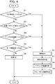
- FIG. 5 is a flowchart of the bearing damage determination process.
- step S11 the damage determination unit 50 determines whether or not the displacement amount of the spindle bearing 30 has exceeded DDmax (mm).
- DDmax is the maximum amount of displacement of the main shaft bearing 30 that is assumed when the main shaft bearing 30 is not damaged, and is set in advance.
- the process proceeds to step S12, and the damage determination unit 50 determines that the spindle bearing 30 has been damaged.
- the process proceeds to step S13, and the damage determination unit 50 determines whether an abnormality has occurred in the spindle system. Determine. Specifically, the damage determination unit 50 detects a rotation abnormality or a rotation loss of the main shaft 32 or an overload of a motor that rotates the main shaft 32 by a controller that controls the rotation of the main shaft 32. When an alarm indicating that an abnormality has occurred in the system is output, it is determined that an abnormality has occurred in the spindle system.
- the process proceeds to step S14, and the damage determination unit 50 estimates the impact force F applied to the main shaft part 24 along the collision direction.
- Tm is the torque generated by the motor 16 at the time of the collision
- M is the inertia of the moving object that has collided with the main shaft portion 24.
- M (weight of the saddle 26) + (weight of the ram 28).
- ⁇ is the acceleration of the ram 28 detected by the acceleration sensor 38.
- step S15 the damage determination unit 50 determines whether or not the impact force F estimated in step S14 exceeds the static load rating of the spindle bearing 30.
- the damage determination unit 50 determines whether or not the impact force F estimated in step S14 exceeds the static load rating of the spindle bearing 30.
- step S13 If no abnormality has occurred in the spindle system in step S13, that is, if an alarm indicating that an abnormality has occurred in the spindle system is not output by the controller that controls the rotation of the spindle 32, or in step S15,
- the process proceeds to step S16, and the damage determination unit 50 is caused by the rotation of the spindle 32.
- the frequency characteristic of the vibration of the ram 28 is acquired.
- the damage determination unit 50 performs frequency analysis of the vibration of the ram 28 due to the rotation of the main shaft 32 based on the acceleration data of the ram 28 detected by the acceleration sensor 38.
- the damage determination part 50 acquires the peak value of the harmonic frequency with respect to the base frequency equivalent to the rotation speed of the main axis
- step S17 the damage determination unit 50 determines whether or not the peak values of the basal frequency and the harmonic frequency of the vibration of the ram 28 acquired in step S16 exceed PDmax.
- the PDmax is a maximum peak value assumed when the main shaft bearing 30 is not damaged, and is set in advance.
- the process proceeds to step S12, and the damage determination unit 50 determines that the main shaft bearing 30 has been damaged.
- the process proceeds to step S18, and the damage determination unit 50 acquires the ram acquired in step S16. It is determined whether or not the frequency characteristics of the vibration 28 coincide with the normal frequency characteristics.
- the damage determination unit 50 determines that the base frequency and the harmonic frequency of the vibration of the ram 28 acquired in step S16 are within a certain range from the base frequency and the harmonic frequency at the normal time, and the base frequency and the harmonics thereof. When the frequency peak value is within a certain range from the normal peak value, it is determined that the frequency characteristic of the vibration of the ram 28 matches the normal frequency characteristic.
- step S12 when the frequency characteristic of the vibration of the ram 28 does not coincide with the normal frequency characteristic, the process proceeds to step S12, and the damage determination unit 50 determines that the main shaft bearing 30 is damaged.
- step S19 if the frequency characteristic of the vibration of the ram 28 matches the normal frequency characteristic, the process proceeds to step S19, and the damage determination unit 50 determines that the spindle bearing 30 is not damaged.
- step S12 or step S19 the damage determination unit 50 ends the bearing damage determination process and returns to the main routine.
- FIG. 6 is a flowchart of the ram / saddle damage determination process.
- the damage determination unit 50 determines whether or not an abnormality has occurred in the drive system of the table 10 in step S21. Specifically, the damage determination unit 50 detects an abnormal rotation or a loss of the ball screw 6 or an overload of the motor 16 by the control unit 18 and indicates that an abnormality has occurred in the drive system of the table 10. Is output, it is determined that an abnormality has occurred in the drive system of the table 10.
- step S22 the damage determination unit 50 determines that the impact force F estimated in step S14 of the bearing damage determination process described with reference to FIG. Determine whether the load is exceeded.
- the ram 28 may be deformed or damaged to the extent that repair is required. Therefore, it progresses to step S23 and the damage determination part 50 determines with the ram 28 having received damage.
- step S21 if no abnormality has occurred in the drive system of the table 10 in step S21, that is, if an alarm indicating that an abnormality has occurred in the drive system of the table 10 has not been output by the control unit 18, or
- step S22 when the impact force F does not exceed the load resistance of the ram 28 (the impact force F is equal to or less than the load resistance of the ram 28), the process proceeds to step S24, where the ram deformation amount estimation unit 48 The amount of displacement L at the tip of 28 is estimated.
- FIG. 7 is a partially enlarged side view showing the ram 28 that is deformed by a collision.
- the ram deformation amount estimation unit 48 estimates the displacement amount L of the tip of the ram 28 at the time of the collision.
- FIG. 8 is a diagram showing the time change of the position of the table 10 before and after the collision.
- the horizontal axis indicates time
- the vertical axis indicates the position of the table 10.
- the time T 0 when the moving speed of the table 10 (that is, the gradient of the time change of the position of the table 10) changes is a collision time.
- the ram deformation amount estimation unit 48 calculates the distance between the position C 0 of the table 10 at the time of the collision and the stop position C 1 at which the position of the table 10 no longer changes, and calculates the distance at the time of the collision.
- the amount of displacement L at the tip of the ram 28 is estimated.
- the damage determination unit 50 determines whether or not the displacement amount L of the tip of the ram 28 estimated by the ram deformation amount estimation unit 48 in step S24 exceeds LDmax.
- This LDmax is the maximum amount of displacement of the tip of the ram 28 that is assumed when the ram 28 and the saddle 26 are not damaged.
- the LDmax is preliminarily set for each collision direction in the X-axis direction, the Y-axis direction, and the Z-axis direction. Is set.
- FIG. 9 is a diagram showing the relationship between the amount of protrusion of the ram 28 from the saddle 26 and LDmax at the time of collision. In FIG.
- the horizontal axis indicates LDmax
- the vertical axis indicates the amount of protrusion of the ram 28 from the saddle 26.
- the collision direction is the X-axis direction
- the ram 28 and the saddle 26 are easily damaged even by a small displacement compared to the other collision directions, so that the LDmax is the smallest compared to the other collision directions.
- LDmax is the largest compared to the other collision directions.
- LDmax is intermediate between the case where the collision direction is the X-axis direction and the case of the Z-axis direction.
- step S25 when the displacement amount L of the tip of the ram 28 estimated by the ram deformation amount estimation unit 48 in step S24 exceeds LDmax, the process proceeds to step S23, where the damage determination unit 50 determines that the ram 28 and the saddle 26 are Determined to have been damaged.
- step S25 when the displacement amount L of the tip of the ram 28 does not exceed LDmax (the displacement amount L of the tip of the ram 28 is equal to or less than LDmax), the process proceeds to step S26, where the damage determination unit 50 It is determined that 26 is not damaged.
- step S23 or step S26 the damage determination unit 50 ends the ram / saddle damage determination process and returns to the main routine.
- the collision determination unit 46 is based on at least one of the displacement amount of the spindle bearing 30 detected by the displacement sensor 36 or the acceleration of the ram 28 detected by the acceleration sensor 38, and the workpiece 12 of the ram 28 or the spindle 32.
- the damage determination unit 50 determines the amount of displacement of the spindle bearing 30, the acceleration of the ram 28,
- the degree of damage to the spindle bearing 30 is determined based on at least one of the frequency characteristics of the vibration of the ram 28 caused by the rotation of the spindle 32 obtained from the acceleration of the ram 28.
- the collision determination unit 46 determines whether or not there is a collision with the workpiece 12 of the main spindle system based on the displacement amount of the main spindle bearing 30 that is deformed by the collision with the main spindle system and the acceleration of the ram 28 that is moved by the collision with the main spindle system. Since it determines, the presence or absence of a collision can be determined directly. Further, the damage determination unit 50 determines the degree of damage of the main shaft bearing 30 based on the displacement amount of the main shaft bearing 30, the acceleration of the ram 28, or the frequency characteristics of the vibration of the ram 28, which changes according to the degree of damage of the main shaft bearing 30.
- the damage determination unit 50 can directly determine the degree of damage to the main shaft bearing 30 by determining the degree of damage to the main shaft bearing 30 based on the amount of displacement of the main shaft bearing 30. Further, the damage determination unit 50 determines the degree of damage of the main shaft bearing 30 based on the frequency characteristics of the vibration of the ram 28 due to the rotation of the main shaft 32, so that the main shaft bearing 30 can be obtained from a plurality of side surfaces such as a base frequency and a peak value. The degree of damage can be determined more precisely.
- the damage determination unit 50 determines the acceleration of the ram 28 detected by the acceleration sensor 38 or the ram deformation amount estimation unit when the collision determination unit 46 determines that there is a collision with the ram 28 or the spindle 32. Based on at least one of the deformation amounts of the ram 28 estimated by 48, the degree of damage of the ram 28 and the saddle 26 is determined. That is, the damage determination unit 50 determines the degree of damage of the ram 28 and the saddle 26 based on the acceleration of the ram 28 that changes according to the degree of damage of the ram 28 and the saddle 26 or the deformation amount of the ram 28. The degree of damage to the ram 28 and the saddle 26 due to the collision of the system can be reliably grasped. In particular, the damage determination unit 50 can directly determine the degree of damage of the ram 28 and the saddle 26 by determining the degree of damage of the ram 28 and the saddle 26 based on the deformation amount of the ram 28.
- the ram deformation amount estimation unit 48 estimates the deformation amount of the ram 28 based on the position change of the table 10 detected by the position detector 20. That is, the ram deformation amount estimation unit 48 estimates the deformation amount of the ram 28 based on the position change of the table 10 when the workpiece 12 installed on the table 10 or the table 10 itself collides with the spindle system. The deformation amount of the ram 28 can be reliably estimated without using a sensor that directly detects the deformation amount.
Landscapes
- Engineering & Computer Science (AREA)
- Mechanical Engineering (AREA)
- Physics & Mathematics (AREA)
- General Physics & Mathematics (AREA)
- Human Computer Interaction (AREA)
- Manufacturing & Machinery (AREA)
- Automation & Control Theory (AREA)
- Testing Of Devices, Machine Parts, Or Other Structures Thereof (AREA)
- Machine Tool Sensing Apparatuses (AREA)
- Numerical Control (AREA)
Abstract
主軸系の衝突による損傷の程度を診断することができる工作機械の異常診断装置及び異常診断方法を提供する。 工作機械(1)の異常診断装置(40)は、主軸ベアリング(30)の変位量を検出する変位センサ(36)と、ラム(28)の加速度を検出する加速度センサ(38)と、変位センサにより検出された主軸ベアリングの変位量、又は、加速度センサにより検出されたラムの加速度の少なくとも何れかに基づき、ラム又は主軸(32)のワークへの衝突の有無を判定する衝突判定部(46)と、衝突判定部によりラム又は主軸のワークへの衝突が有ったと判定された場合に、主軸ベアリングの変位量、ラムの加速度、又は、このラムの加速度から得られた主軸の回転によるラムの振動の周波数特性の少なくとも何れかに基づき、主軸ベアリングの損傷程度を判定する損傷判定部(50)と、を有する。
Description
本発明は、工作機械の異常診断装置及び異常診断方法に係わり、特に、ワークを加工する工具が主軸に取り付けられ、この主軸が軸受によって支持される工作機械の異常診断装置及び異常診断方法に関する。
従来より、軸受によって支持された主軸を有する工作機械が使用されている。この工作機械では、主軸に取り付けられた工具とワークとを相対的に移動させることにより、ワークに各種の加工を行う。このように、主軸に取り付けられた工具とワークとを相対的に移動させる際に、工具又はワークの移動方向や移動量を規定するNC(Numerical Control)プログラムの入力ミスや作業者の操作ミスにより、主軸、工具、ワーク等を衝突させ、工作機械を損傷させてしまう場合がある。
そこで、このような衝突による工作機械の損傷の程度を判断し、機械の部品交換が必要であるか否かを判断するための工作機械の制御装置が提案されている。例えば、特許文献1に記載されている工作機械の制御装置は、工作機械の動作時にテーブルやテーブル積載物が主軸などと衝突した場合、テーブルを駆動するボールネジに作用した衝突の負荷を算出し、その算出した負荷をあらかじめ設定された基準値と比較することにより、ボールネジに対する衝撃の大きさを判定する。
工作機械に発生し得る衝突の中では、主軸系の衝突の発生頻度が特に高い。この主軸系の衝突では、主軸に取り付けられた工具や主軸自体の損傷に留まらず、主軸を支持する軸受、主軸を回転させるモータ、あるいは軸受を介して主軸を支持する支持構造体にまで損傷が及ぶ場合もあり、被害が大きくなり易い。従って、主軸系の衝突による損傷の程度を的確に把握することが要求される。
しかしながら、特許文献1に記載されている工作機械の制御装置は、テーブルを駆動する駆動系の衝突による損傷診断を行うものであり、上述した主軸系の衝突による損傷の程度を診断することができない。
本発明は、上述した従来技術の問題点を解決するためになされたものであり、主軸系の衝突による損傷の程度を診断することができる工作機械の異常診断装置及び異常診断方法を提供することを目的とする。
上記の目的を達成するために、本発明の第1発明による工作機械の異常診断装置は、ワークを加工する工具が主軸に取り付けられ、この主軸が軸受により支持され、この軸受が支持構造体により支持される工作機械の異常診断装置において、軸受の変位量を検出する軸受変位量検出手段と、支持構造体の加速度を検出する加速度検出手段と、軸受変位量検出手段により検出された軸受の変位量、又は、加速度検出手段により検出された支持構造体の加速度の少なくとも何れかに基づき、支持構造体又は主軸のワークへの衝突の有無を判定する衝突判定手段と、衝突判定手段により支持構造体又は主軸のワークへの衝突が有ったと判定された場合に、軸受の変位量、支持構造体の加速度、又は、この支持構造体の加速度から得られた主軸の回転による支持構造体の振動の周波数特性の少なくとも何れかに基づき、軸受の損傷程度を判定する損傷判定手段と、を有することを特徴とする。
このように構成された本発明においては、衝突判定手段は、主軸系の衝突により変形する軸受の変位量や、主軸系の衝突により移動する支持構造体の加速度に基づき、主軸系のワークへの衝突の有無を判定するので、衝突の有無を直接的に判定することができる。また、損傷判定手段は、軸受の損傷程度に応じて変化する軸受の変位量、支持構造体の加速度、又は、支持構造体の振動の周波数特性に基づいて、軸受の損傷程度を判定するので、主軸系の衝突による軸受の損傷の程度を確実に把握することができる。特に、損傷判定手段が、軸受の変位量に基づいて軸受の損傷程度を判定することにより、軸受の損傷程度を直接的に判定することができる。また、損傷判定手段が、主軸の回転による支持構造体の振動の周波数特性に基づいて軸受の損傷程度を判定することにより、基底周波数やピーク値等の複数の側面から、軸受の損傷程度をより厳密に判定することができる。
このように構成された本発明においては、衝突判定手段は、主軸系の衝突により変形する軸受の変位量や、主軸系の衝突により移動する支持構造体の加速度に基づき、主軸系のワークへの衝突の有無を判定するので、衝突の有無を直接的に判定することができる。また、損傷判定手段は、軸受の損傷程度に応じて変化する軸受の変位量、支持構造体の加速度、又は、支持構造体の振動の周波数特性に基づいて、軸受の損傷程度を判定するので、主軸系の衝突による軸受の損傷の程度を確実に把握することができる。特に、損傷判定手段が、軸受の変位量に基づいて軸受の損傷程度を判定することにより、軸受の損傷程度を直接的に判定することができる。また、損傷判定手段が、主軸の回転による支持構造体の振動の周波数特性に基づいて軸受の損傷程度を判定することにより、基底周波数やピーク値等の複数の側面から、軸受の損傷程度をより厳密に判定することができる。
また、本発明において、好ましくは、工作機械の異常診断装置は、支持構造体の変形量を推定する支持構造体変形量推定手段を有し、損傷判定手段は、衝突判定手段により支持構造体又は主軸への衝突が有ったと判定された場合に、加速度検出手段により検出された支持構造体の加速度、又は、支持構造体変形量推定手段により推定された支持構造体の変形量の少なくとも何れかに基づき、支持構造体の損傷程度を判定する。
このように構成された本発明においては、損傷判定手段は、支持構造体の損傷程度に応じて変化する支持構造体の加速度、又は、支持構造体の変形量に基づいて、支持構造体の損傷程度を判定するので、主軸系の衝突による支持構造体の損傷の程度を確実に把握することができる。特に、損傷判定手段が、支持構造体の変形量に基づいて支持構造体の損傷程度を判定することにより、支持構造体の損傷程度を直接的に判定することができる。
このように構成された本発明においては、損傷判定手段は、支持構造体の損傷程度に応じて変化する支持構造体の加速度、又は、支持構造体の変形量に基づいて、支持構造体の損傷程度を判定するので、主軸系の衝突による支持構造体の損傷の程度を確実に把握することができる。特に、損傷判定手段が、支持構造体の変形量に基づいて支持構造体の損傷程度を判定することにより、支持構造体の損傷程度を直接的に判定することができる。
また、本発明において、好ましくは、工作機械は、主軸の軸線方向と直交する方向に移動する移動体と、この移動体の位置を検出する位置検出手段と、を有し、支持構造体変形量推定手段は、位置検出手段により検出された移動体の位置変化に基づき、支持構造体の変形量を推定する。
このように構成された本発明においては、支持構造体変形量推定部は、移動体が主軸系と衝突した場合の移動体の位置変化に基づき、支持構造体の変形量を推定するので、支持構造体の変形量を直接検出するセンサを用いることなく、支持構造体の変形量を確実に推定することができる。
このように構成された本発明においては、支持構造体変形量推定部は、移動体が主軸系と衝突した場合の移動体の位置変化に基づき、支持構造体の変形量を推定するので、支持構造体の変形量を直接検出するセンサを用いることなく、支持構造体の変形量を確実に推定することができる。
また、本発明の第2発明による工作機械の異常診断方法は、ワークを加工する工具が主軸に取り付けられ、この主軸が軸受により支持され、この軸受が支持構造体により支持される工作機械の異常診断方法において、軸受の変位量を検出するステップと、支持構造体の加速度を検出するステップと、検出された軸受の変位量、又は、支持構造体の加速度の少なくとも何れかに基づき、支持構造体又は主軸のワークへの衝突の有無を判定するステップと、支持構造体又は主軸のワークへの衝突が有ったと判定された場合に、検出された軸受の変位量、若しくは、支持構造体の加速度、又は、この支持構造体の加速度から得られた主軸の回転による支持構造体の振動の周波数特性の少なくとも何れかに基づき、軸受の損傷程度を判定するステップと、を有することを特徴とする。
本発明による工作機械の異常診断装置及び異常診断方法によれば、主軸系の衝突による損傷の程度を診断することができる。
以下、添付図面を参照して、本発明の実施形態による異常診断装置及び異常診断方法を説明する。
まず、図1及び図2により、本発明の実施形態による異常診断装置が適用される工作機械について説明する。図1は、本発明の実施形態による異常診断装置が適用される工作機械の概略斜視図である。図2は、本発明の実施形態による異常診断装置が適用される工作機械の主軸部の部分拡大側面図である。
まず、図1及び図2により、本発明の実施形態による異常診断装置が適用される工作機械について説明する。図1は、本発明の実施形態による異常診断装置が適用される工作機械の概略斜視図である。図2は、本発明の実施形態による異常診断装置が適用される工作機械の主軸部の部分拡大側面図である。
図1に示すように、符号1は、工作機械を示し、この工作機械1は、床面に設置されるベッド2を有している。このベッド2の上面には、複数のブラケット4が固定されている。各ブラケット4には支持ベアリングが取り付けられており、これらの支持ベアリングにより、ボールスクリュー6の両端部分が回転可能に支持されている。
以下の説明では、ボールスクリュー6の長手軸線方向をX軸方向とし、水平面内においてX軸と直交する方向をY軸方向とし、鉛直方向をZ軸方向とする。
以下の説明では、ボールスクリュー6の長手軸線方向をX軸方向とし、水平面内においてX軸と直交する方向をY軸方向とし、鉛直方向をZ軸方向とする。
ブラケット4の間に位置しているボールスクリュー6のネジ部には、ナット8が螺合されており、このナット8にテーブル10が固定されている。このテーブル10の上面に、工作機械1による加工対象物であるワーク12が設置される。
ボールスクリュー6には、減速ギヤ14を介してモータ16が連結されており、モータ16の駆動力が減速ギヤ14を介してボールスクリュー6に伝達されるようになっている。モータ16は、制御部18によって制御される。
さらに、テーブル10の近傍にはテーブル10の位置を検出する位置検出器20が設けられている。また、モータ16には、モータ16の回転速度を検出するパルスコーダ22が取り付けられている。
制御部18は、テーブル10の位置を指示する位置指令、テーブル10の位置を検出する位置検出器20から出力される位置フィードバック、及び、モータ16の回転速度を検出するパルスコーダ22から出力される速度フィードバックに基づき、モータ16を駆動して、テーブル10の移動速度や位置等を制御する。
制御部18は、テーブル10の位置を指示する位置指令、テーブル10の位置を検出する位置検出器20から出力される位置フィードバック、及び、モータ16の回転速度を検出するパルスコーダ22から出力される速度フィードバックに基づき、モータ16を駆動して、テーブル10の移動速度や位置等を制御する。
また、工作機械1は、ベッド2を跨ぐように配設された門形のコラム(図示せず)を有しており、このコラムに、主軸部24が取り付けられている。図2は、本発明の実施形態による工作機械の異常診断装置が適用される工作機械1の主軸部24の部分拡大側面図である。
図2に示すように、主軸部24は、サドル26を有している。サドル26は、Y軸方向に沿って移動可能にコラムに取り付けられている。このサドル26により、ラム28が、Z軸方向に沿って直動可能に支持されている。
ラム28の内部には主軸ベアリング30が設けられており、この主軸ベアリング30により、主軸32がZ軸を中心に回転可能に支持されている。主軸32は、ラム28の下端からZ軸方向に沿って下向きに突出しており、主軸32の先端部に工具34が装着される。
次に、異常診断装置40を説明する。主軸ベアリング30には、この主軸ベアリング30の変位量(変形量)を検出する変位センサ36が取り付けられている。この変位センサ36としては、歪ゲージや圧電素子が使用される。
また、主軸ベアリング30を介して主軸32を支持する支持構造体であるラム28の下端部には、ラム28の下端部の加速度を検出する加速度センサ38が取り付けられている。この加速度センサ38は、X軸、Y軸、及び、Z軸の3軸方向の加速度を検出可能な3軸加速度センサである。
また、主軸ベアリング30を介して主軸32を支持する支持構造体であるラム28の下端部には、ラム28の下端部の加速度を検出する加速度センサ38が取り付けられている。この加速度センサ38は、X軸、Y軸、及び、Z軸の3軸方向の加速度を検出可能な3軸加速度センサである。
制御部18が、テーブル10の位置を指示する位置指令、テーブル10の位置を検出する位置検出器20から出力される位置フィードバック、及び、モータ16の回転速度を検出するパルスコーダ22から出力される速度フィードバックに基づき、モータ16を駆動させると、モータ16の駆動力が減速ギヤ14を介してボールスクリュー6に伝達され、ボールスクリュー6が回転する。これにより、ナット8と共にテーブル10がボールスクリュー6の軸線方向(X軸方向)に沿って直動し、テーブル10に設置されたワーク12を所望の位置に移動させる。
作業者の操作ミス等により、テーブル10上のワーク12が主軸部24に衝突すると、その衝撃によりラム28や主軸32が変形し、主軸32の変形により主軸ベアリング30も変形する。この主軸ベアリング30の変位量を変位センサ36が検出し、ラム28の変形に伴う加速度を加速度センサ38が検出する。
作業者の操作ミス等により、テーブル10上のワーク12が主軸部24に衝突すると、その衝撃によりラム28や主軸32が変形し、主軸32の変形により主軸ベアリング30も変形する。この主軸ベアリング30の変位量を変位センサ36が検出し、ラム28の変形に伴う加速度を加速度センサ38が検出する。
次に、図3により、本発明の実施形態による異常診断装置40の電気的な構成を説明する。図3は、本発明の実施形態による異常診断装置40のブロック図である。
図3に示すように、異常診断装置40は、変位センサ36、加速度センサ38、及び、工作機械1の異常を診断する異常診断部42を備える。この異常診断部42は、変位センサ36により検出された主軸ベアリング30の変位量、加速度センサ38により検出されたラム28の加速度、位置検出器20から出力される位置フィードバック、パルスコーダ22から出力される速度フィードバック、及び、制御部18から出力されるモータ電流値に基づき、工作機械1の異常を診断する。
異常診断部42は、変位センサ36により検出された主軸ベアリング30の変位データ、加速度センサ38により検出されたラム28の加速度データ、位置検出器20から出力される位置フィードバックデータ、パルスコーダ22から出力される速度フィードバックデータ、及び、制御部18から出力されるモータ電流値を記憶する記憶部44を備える。
また、異常診断部42は、記憶部44に記憶されている主軸ベアリング30の変位データやラム28の加速度データに基づき、主軸部24への衝突の有無を判定する衝突判定部46と、衝突によるラム28の変形量を推定するラム変形量推定部48と、記憶部44に記憶されている主軸ベアリング30の変位データやラム28の加速度データ等に基づき、主軸ベアリング30、ラム28、及びサドル26の損傷程度を判定する損傷判定部50とを備えている。
異常診断部42は、変位センサ36により検出された主軸ベアリング30の変位データ、加速度センサ38により検出されたラム28の加速度データ、位置検出器20から出力される位置フィードバックデータ、パルスコーダ22から出力される速度フィードバックデータ、及び、制御部18から出力されるモータ電流値を記憶する記憶部44を備える。
また、異常診断部42は、記憶部44に記憶されている主軸ベアリング30の変位データやラム28の加速度データに基づき、主軸部24への衝突の有無を判定する衝突判定部46と、衝突によるラム28の変形量を推定するラム変形量推定部48と、記憶部44に記憶されている主軸ベアリング30の変位データやラム28の加速度データ等に基づき、主軸ベアリング30、ラム28、及びサドル26の損傷程度を判定する損傷判定部50とを備えている。
次に、図4乃至図6により、本発明の実施形態による異常診断装置40が行う各処理について説明する。
図4は、本発明の実施形態による異常診断装置40が行う異常診断処理のフローチャートである。この異常診断処理は、工作機械1によるワーク12の加工が開始された場合に実行される。
図4に示すように、異常診断処理が開始されると、ステップS1において、衝突判定部46は、加速度センサ38により検出されたラム28の加速度がαCmax(m/s2)を超えたか否かを判定する。このαCmaxは、モータ16がボールスクリュー6を回転させ、このボールスクリュー6の回転によりテーブル10を移動させる際の最大加速度であり、テーブル10の位置を制御するための数値制御パラメータにより定義される。衝突が発生していない正常な使用状況においては、テーブル10がαCmaxを超える加速度により移動することは考えられない。従って、ラム28の加速度がαCmaxを超えた場合、衝突判定部46は、ステップS2に進み、主軸部24に対する衝突が有ったものと判定する。
一方、ラム28の加速度がαCmaxを超えていない(ラム28の加速度がαCmax以下である)場合、ステップS3に進み、衝突判定部46は、主軸ベアリング30の変位量がDCmax(mm)を超えたか否かを判定する。このDCmaxは、主軸部24に対する衝突が発生していない場合に想定される主軸ベアリング30の最大変位量であり、予め設定されている。主軸ベアリング30の変位量がDCmaxを超えた場合、衝突判定部46は、ステップS2に進み、主軸部24に対する衝突が有ったものと判定する。
一方、主軸ベアリング30の変位量がDCmaxを超えていない(主軸ベアリング30の変位量がDCmax以下である)場合、ステップS4に進み、衝突判定部46は、テーブル10の加速度がαCmaxを超えたか否かを判定する。具体的には、衝突判定部46は、速度フィードバックデータ及び位置フィードバックデータに基づき、テーブル10の加速度を算出し、この算出したテーブル10の加速度がαCmaxを超えている場合、衝突判定部46は、ステップS2に進み、主軸部24に対する衝突が有ったものと判定する。
一方、テーブル10の加速度αCmaxを超えていない(テーブル10の加速度がαCmax以下である)場合、ステップS5に進み、衝突判定部46は、モータ16の電流値がICmax(A)を超えたか否かを判定する。このICmaxは、主軸部24に対する衝突が発生していない場合に想定されるモータ16の最大電流値であり、予め設定されている。モータ16の電流値がICmaxを超えた場合、衝突判定部46は、ステップS2に進み、主軸部24に対する衝突が有ったものと判定する。
一方、モータ16の電流値がICmaxを超えていない(モータ16の電流値がICmax以下である)場合、ステップS6に進み、衝突判定部46は、主軸部24に対する衝突が発生していないものと判定する。ステップS6の後、異常診断部42は異常診断処理を終了する。
ステップS2において、主軸部24に対する衝突が有ったものと衝突判定部46が判定した後、ステップS7に進み、衝突判定部46は、衝突の方向を判定する。具体的には、衝突判定部46は、位置フィードバックデータ、速度フィードバックデータ、又は、モータ電流値に基づき、主軸部24に対する衝突の発生時を特定する。例えば、衝突判定部46は、位置フィードバックデータや速度フィードバックデータに基づき、テーブル10の移動速度が変化した時点を特定し、その時点を衝突時とする。そして、衝突判定部46は、衝突時におけるテーブル10の移動方向を特定し、その移動方向を衝突方向とする。あるいは、衝突判定部46は、加速度センサ38により検出されたラム28のX軸、Y軸、及び、Z軸方向の各加速度に基づき、衝突方向を判定する。
次に、ステップS8に進み、損傷判定部50は、主軸ベアリング30の変位データやラム28の加速度データ等に基づき、主軸ベアリング30の損傷程度を判定する(ベアリング損傷判定処理)。続いて、ステップS9に進み、損傷判定部50は、主軸ベアリング30の変位データやラム28の加速度データ等に基づき、ラム28とサドル26の損傷程度を判定する(ラム・サドル損傷判定処理)。ステップS9の後、異常診断部42は異常診断処理を終了する。
次に、異常診断処理のステップS8において損傷判定部50が実行するベアリング損傷判定処理を説明する。図5は、ベアリング損傷判定処理のフローチャートである。
図5に示すように、ベアリング損傷判定処理が開始されると、ステップS11において、損傷判定部50は、主軸ベアリング30の変位量がDDmax(mm)を超えたか否かを判定する。このDDmaxは、主軸ベアリング30が損傷を受けていない場合に想定される主軸ベアリング30の最大変位量であり、予め設定されている。主軸ベアリング30の変位量がDDmaxを超えた場合、ステップS12に進み、損傷判定部50は、主軸ベアリング30が損傷を受けたものと判定する。
一方、主軸ベアリング30の変位量がDDmaxを超えていない(主軸ベアリング30の変位量がDDmax以下である)場合、ステップS13に進み、損傷判定部50は、主軸系に異常が発生したか否かを判定する。具体的には、損傷判定部50は、主軸32の回転を制御するコントローラにより、主軸32の回転異常や回転損失、あるいは、主軸32を回転させるモータの過負荷が検出され、このコントローラにより、主軸系に異常が発生した旨のアラームが出力された場合に、主軸系に異常が発生したと判定する。
その結果、主軸系に異常が発生した場合、ステップS14に進み、損傷判定部50は、衝突方向に沿って主軸部24に加えられた衝撃力Fを推定する。損傷判定部50は、F=Tm+(M・α)により衝撃力Fを算出する。ここで、Tmは、衝突時にモータ16が発生させていたトルクであり、損傷判定部50は、モータ電流値に基づきTmを算出する。また、Mは、主軸部24に衝突した移動物体のイナーシャである。より詳細には、図4により説明した異常診断処理のステップS7において衝突判定部46により判定された衝突方向がX軸方向である場合、損傷判定部50は、M=(テーブル10の重量)+(ワーク12の重量)によりMを算出する。また、衝突判定部46により判定された衝突方向がY軸方向である場合、損傷判定部50は、M=(サドル26の重量)+(ラム28の重量)によりMを算出する。また、衝突判定部46により判定された衝突方向がZ軸方向である場合、損傷判定部50は、M=ラム28の重量によりMを算出する。また、αは、加速度センサ38により検出されたラム28の加速度である。
次に、ステップS15に進み、損傷判定部50は、ステップS14において推定した衝撃力Fが、主軸ベアリング30の静定格荷重を超えているか否かを判定する。その結果、衝撃力Fが、主軸ベアリング30の静定格荷重を超えている場合、交換を要する程度の変形や損傷が主軸ベアリング30に生じている可能性がある。従って、ステップS12に進み、損傷判定部50は、主軸ベアリング30が損傷を受けたものと判定する。
ステップS13において、主軸系に異常が発生していない場合、即ち、主軸32の回転を制御するコントローラにより、主軸系に異常が発生した旨のアラームが出力されていない場合、又は、ステップS15において、衝撃力Fが、主軸ベアリング30の静定格荷重を超えていない(衝撃力Fが主軸ベアリング30の静定格荷重以下である)場合、ステップS16に進み、損傷判定部50は、主軸32の回転によるラム28の振動の周波数特性を取得する。具体的には、損傷判定部50は、加速度センサ38により検出されたラム28の加速度データに基づき、主軸32の回転によるラム28の振動の周波数解析を行う。そして、損傷判定部50は、主軸32の回転数に相当する基底周波数、及び、その基底周波数に対する高調波周波数のピーク値を取得する。
次に、ステップS17において、損傷判定部50は、ステップS16において取得したラム28の振動の基底周波数及び高調波周波数のピーク値がPDmaxを超えているか否かを判定する。このPDmaxは、主軸ベアリング30が損傷を受けていない場合に想定される最大ピーク値であり、予め設定されている。ラム28の振動の基底周波数及び高調波周波数のピーク値がPDmaxを超えている場合、ステップS12に進み、損傷判定部50は、主軸ベアリング30が損傷を受けたものと判定する。
一方、ラム28の振動の基底周波数及び高調波周波数のピーク値がPDmaxを超えていない(ピーク値がPDmax以下である)場合、ステップS18に進み、損傷判定部50は、ステップS16において取得したラム28の振動の周波数特性が、正常時の周波数特性と一致するか否かを判定する。損傷判定部50は、ステップS16において取得したラム28の振動の基底周波数及び高調波周波数が、正常時の基底周波数及び高調波周波数から一定の範囲内にあり、且つ、それらの基底周波数及び高調波周波数のピーク値が、正常時のピーク値から一定の範囲内にある場合に、ラム28の振動の周波数特性が、正常時の周波数特性と一致すると判定する。
その結果、ラム28の振動の周波数特性が、正常時の周波数特性と一致しない場合、ステップS12に進み、損傷判定部50は、主軸ベアリング30が損傷を受けたものと判定する。
一方、ラム28の振動の周波数特性が、正常時の周波数特性と一致する場合、ステップS19に進み、損傷判定部50は、主軸ベアリング30が損傷を受けていないものと判定する。
一方、ラム28の振動の周波数特性が、正常時の周波数特性と一致する場合、ステップS19に進み、損傷判定部50は、主軸ベアリング30が損傷を受けていないものと判定する。
ステップS12又はステップS19の後、損傷判定部50はベアリング損傷判定処理を終了し、メインルーチンに戻る。
次に、異常診断処理のステップS9において損傷判定部50が実行するラム損傷判定処理を説明する。図6は、ラム・サドル損傷判定処理のフローチャートである。
図6に示すように、ラム・サドル損傷判定処理が開始されると、ステップS21において、損傷判定部50は、テーブル10の駆動系に異常が発生したか否かを判定する。具体的には、損傷判定部50は、制御部18により、ボールスクリュー6の回転異常や回転損失、あるいは、モータ16の過負荷が検出され、テーブル10の駆動系に異常が発生した旨のアラームが出力された場合に、テーブル10の駆動系に異常が発生したと判定する。
その結果、テーブル10の駆動系に異常が発生した場合、ステップS22に進み、損傷判定部50は、図5により説明したベアリング損傷判定処理のステップS14において推定した衝撃力Fが、ラム28の耐荷重を超えているか否かを判定する。その結果、衝撃力Fが、ラム28の耐荷重を超えている場合、修理を要する程度の変形や損傷がラム28に生じている可能性がある。従って、ステップS23に進み、損傷判定部50は、ラム28が損傷を受けたものと判定する。
一方、ステップS21において、テーブル10の駆動系に異常が発生していない場合、即ち、制御部18により、テーブル10の駆動系に異常が発生した旨のアラームが出力されていない場合、又は、ステップS22において、衝撃力Fが、ラム28の耐荷重を超えていない(衝撃力Fがラム28の耐荷重以下である)場合、ステップS24に進み、ラム変形量推定部48は、衝突時のラム28の先端の変位量Lを推定する。
図7は、衝突により変形するラム28を示す部分拡大側面図である。移動するテーブル10に設置されているワーク12がラム28に衝突すると、図7において破線により示すように、衝突方向に沿ってラム28が変形する。ラム変形量推定部48は、この衝突時のラム28の先端の変位量Lを推定する。
図8は、衝突前後におけるテーブル10の位置の時間変化を示す線図である。この図8において、横軸は時間を示し、縦軸はテーブル10の位置を示す。
図8に示すように、テーブル10の移動速度(即ちテーブル10の位置の時間変化の傾き)が変化した時点T0が衝突時である。ラム変形量推定部48は、位置フィードバックデータに基づき、衝突時におけるテーブル10の位置C0と、テーブル10の位置が変化しなくなった停止位置C1との距離を算出し、その距離を衝突時のラム28の先端の変位量Lとして推定する。
図8に示すように、テーブル10の移動速度(即ちテーブル10の位置の時間変化の傾き)が変化した時点T0が衝突時である。ラム変形量推定部48は、位置フィードバックデータに基づき、衝突時におけるテーブル10の位置C0と、テーブル10の位置が変化しなくなった停止位置C1との距離を算出し、その距離を衝突時のラム28の先端の変位量Lとして推定する。
次に、ステップS25に進み、損傷判定部50は、ステップS24においてラム変形量推定部48により推定されたラム28の先端の変位量Lが、LDmaxを超えたか否かを判定する。このLDmaxは、ラム28とサドル26が損傷を受けていない場合に想定されるラム28の先端の最大変位量であり、X軸方向、Y軸方向、及び、Z軸方向の各衝突方向について予め設定されている。
図9は、衝突時のラム28のサドル26からの突出量とLDmaxとの関係を示す線図である。この図9において、横軸はLDmaxを示し、縦軸はラム28のサドル26からの突出量を示す。
図9に示すように、ラム28のサドル26からの突出量が大きくなるほど、小さい変位でもラム28とサドル26が損傷しやすくなるので、LDmaxが小さくなっている。
また、衝突方向がX軸方向の場合、他の衝突方向と比較して小さい変位でもラム28とサドル26が損傷しやすいので、他の衝突方向と比較してLDmaxが最も小さくなっている。これに対し、衝突方向がZ軸方向の場合、他の衝突方向と比較して大きい変位でもラム28とサドル26が損傷しにくいので、他の衝突方向と比較してLDmaxが最も大きくなっている。衝突方向がY軸方向の場合、LDmaxは、衝突方向がX軸方向の場合とZ軸方向の場合との中間の大きさとなっている。
図9は、衝突時のラム28のサドル26からの突出量とLDmaxとの関係を示す線図である。この図9において、横軸はLDmaxを示し、縦軸はラム28のサドル26からの突出量を示す。
図9に示すように、ラム28のサドル26からの突出量が大きくなるほど、小さい変位でもラム28とサドル26が損傷しやすくなるので、LDmaxが小さくなっている。
また、衝突方向がX軸方向の場合、他の衝突方向と比較して小さい変位でもラム28とサドル26が損傷しやすいので、他の衝突方向と比較してLDmaxが最も小さくなっている。これに対し、衝突方向がZ軸方向の場合、他の衝突方向と比較して大きい変位でもラム28とサドル26が損傷しにくいので、他の衝突方向と比較してLDmaxが最も大きくなっている。衝突方向がY軸方向の場合、LDmaxは、衝突方向がX軸方向の場合とZ軸方向の場合との中間の大きさとなっている。
ステップS25の結果、ステップS24においてラム変形量推定部48により推定されたラム28の先端の変位量LがLDmaxを超えた場合、ステップS23に進み、損傷判定部50は、ラム28とサドル26が損傷を受けたものと判定する。
ステップS25において、ラム28の先端の変位量LがLDmaxを超えていない(ラム28の先端の変位量LがLDmax以下である)場合、ステップS26に進み、損傷判定部50は、ラム28とサドル26が損傷を受けていないものと判定する。
ステップS23又はステップS26の後、損傷判定部50はラム・サドル損傷判定処理を終了し、メインルーチンに戻る。
次に、上述した本実施形態の異常診断装置40及び異常診断方法による作用効果を説明する。
まず、衝突判定部46は、変位センサ36により検出された主軸ベアリング30の変位量、又は、加速度センサ38により検出されたラム28の加速度の少なくとも何れかに基づき、ラム28又は主軸32のワーク12への衝突の有無を判定し、損傷判定部50は、衝突判定部46によりラム28又は主軸32への衝突が有ったと判定された場合に、主軸ベアリング30の変位量、ラム28の加速度、又は、このラム28の加速度から得られた主軸32の回転によるラム28の振動の周波数特性の少なくとも何れかに基づき、主軸ベアリング30の損傷程度を判定する。
即ち、衝突判定部46は、主軸系への衝突により変形する主軸ベアリング30の変位量や、主軸系への衝突により移動するラム28の加速度に基づき、主軸系のワーク12への衝突の有無を判定するので、衝突の有無を直接的に判定することができる。また、損傷判定部50は、主軸ベアリング30の損傷程度に応じて変化する主軸ベアリング30の変位量、ラム28の加速度、又は、ラム28の振動の周波数特性に基づいて、主軸ベアリング30の損傷程度を判定するので、主軸系の衝突による主軸ベアリング30の損傷の程度を確実に把握することができる。特に、損傷判定部50が、主軸ベアリング30の変位量に基づいて主軸ベアリング30の損傷程度を判定することにより、主軸ベアリング30の損傷程度を直接的に判定することができる。また、損傷判定部50が、主軸32の回転によるラム28の振動の周波数特性に基づいて主軸ベアリング30の損傷程度を判定することにより、基底周波数やピーク値等の複数の側面から、主軸ベアリング30の損傷程度をより厳密に判定することができる。
即ち、衝突判定部46は、主軸系への衝突により変形する主軸ベアリング30の変位量や、主軸系への衝突により移動するラム28の加速度に基づき、主軸系のワーク12への衝突の有無を判定するので、衝突の有無を直接的に判定することができる。また、損傷判定部50は、主軸ベアリング30の損傷程度に応じて変化する主軸ベアリング30の変位量、ラム28の加速度、又は、ラム28の振動の周波数特性に基づいて、主軸ベアリング30の損傷程度を判定するので、主軸系の衝突による主軸ベアリング30の損傷の程度を確実に把握することができる。特に、損傷判定部50が、主軸ベアリング30の変位量に基づいて主軸ベアリング30の損傷程度を判定することにより、主軸ベアリング30の損傷程度を直接的に判定することができる。また、損傷判定部50が、主軸32の回転によるラム28の振動の周波数特性に基づいて主軸ベアリング30の損傷程度を判定することにより、基底周波数やピーク値等の複数の側面から、主軸ベアリング30の損傷程度をより厳密に判定することができる。
また、損傷判定部50は、衝突判定部46によりラム28又は主軸32への衝突が有ったと判定された場合に、加速度センサ38により検出されたラム28の加速度、又は、ラム変形量推定部48により推定されたラム28の変形量の少なくとも何れかに基づき、ラム28とサドル26の損傷程度を判定する。
即ち、損傷判定部50は、ラム28とサドル26の損傷程度に応じて変化するラム28の加速度、又は、ラム28の変形量に基づいてラム28とサドル26の損傷程度を判定するので、主軸系の衝突によるラム28とサドル26の損傷の程度を確実に把握することができる。特に、損傷判定部50が、ラム28の変形量に基づいてラム28とサドル26の損傷程度を判定することにより、ラム28とサドル26の損傷程度を直接的に判定することができる。
即ち、損傷判定部50は、ラム28とサドル26の損傷程度に応じて変化するラム28の加速度、又は、ラム28の変形量に基づいてラム28とサドル26の損傷程度を判定するので、主軸系の衝突によるラム28とサドル26の損傷の程度を確実に把握することができる。特に、損傷判定部50が、ラム28の変形量に基づいてラム28とサドル26の損傷程度を判定することにより、ラム28とサドル26の損傷程度を直接的に判定することができる。
また、ラム変形量推定部48は、位置検出器20により検出されたテーブル10の位置変化に基づき、ラム28の変形量を推定する。即ち、ラム変形量推定部48は、テーブル10に設置されたワーク12やテーブル10自体が主軸系と衝突した場合のテーブル10の位置変化に基づき、ラム28の変形量を推定するので、ラム28の変形量を直接検出するセンサを用いることなく、ラム28の変形量を確実に推定することができる。
1 工作機械
2 ベッド
4 ブラケット
6 ボールスクリュー
8 ナット
10 テーブル
12 ワーク
14 減速ギヤ
16 モータ
18 制御部
20 位置検出器
22 パルスコーダ
24 主軸部
26 サドル
28 ラム
30 主軸ベアリング
32 主軸
34 工具
36 変位センサ
38 加速度センサ
40 異常診断装置
42 異常診断部
44 記憶部
46 衝突判定部
48 ラム変形量推定部
50 損傷判定部
2 ベッド
4 ブラケット
6 ボールスクリュー
8 ナット
10 テーブル
12 ワーク
14 減速ギヤ
16 モータ
18 制御部
20 位置検出器
22 パルスコーダ
24 主軸部
26 サドル
28 ラム
30 主軸ベアリング
32 主軸
34 工具
36 変位センサ
38 加速度センサ
40 異常診断装置
42 異常診断部
44 記憶部
46 衝突判定部
48 ラム変形量推定部
50 損傷判定部
Claims (4)
- ワークを加工する工具が主軸に取り付けられ、この主軸が軸受により支持され、この軸受が支持構造体により支持される工作機械の異常診断装置において、
上記軸受の変位量を検出する軸受変位量検出手段と、
上記支持構造体の加速度を検出する加速度検出手段と、
上記軸受変位量検出手段により検出された上記軸受の変位量、又は、上記加速度検出手段により検出された上記支持構造体の加速度の少なくとも何れかに基づき、上記支持構造体又は上記主軸のワークへの衝突の有無を判定する衝突判定手段と、
上記衝突判定手段により上記支持構造体又は上記主軸のワークへの衝突が有ったと判定された場合に、上記軸受の変位量、上記支持構造体の加速度、又は、この支持構造体の加速度から得られた上記主軸の回転による上記支持構造体の振動の周波数特性の少なくとも何れかに基づき、上記軸受の損傷程度を判定する損傷判定手段と、
を有することを特徴とする工作機械の異常診断装置。 - 上記支持構造体の変形量を推定する支持構造体変形量推定手段を有し、
上記損傷判定手段は、上記衝突判定手段により上記支持構造体又は上記主軸への衝突が有ったと判定された場合に、上記加速度検出手段により検出された上記支持構造体の加速度、又は、上記支持構造体変形量推定手段により推定された上記支持構造体の変形量の少なくとも何れかに基づき、上記支持構造体の損傷程度を判定する、請求項1に記載の工作機械の異常診断装置。 - 上記工作機械は、上記主軸の軸線方向と直交する方向に移動する移動体と、この移動体の位置を検出する位置検出手段と、を有し、
上記支持構造体変形量推定手段は、上記位置検出手段により検出された上記移動体の位置変化に基づき、上記支持構造体の変形量を推定する、請求項2に記載の工作機械の異常診断装置。 - ワークを加工する工具が主軸に取り付けられ、この主軸が軸受により支持され、この軸受が支持構造体により支持される工作機械の異常診断方法において、
上記軸受の変位量を検出するステップと、
上記支持構造体の加速度を検出するステップと、
上記検出された上記軸受の変位量、又は、上記支持構造体の加速度の少なくとも何れかに基づき、上記支持構造体又は上記主軸のワークへの衝突の有無を判定するステップと、 上記支持構造体又は上記主軸のワークへの衝突が有ったと判定された場合に、上記検出された上記軸受の変位量、若しくは、上記支持構造体の加速度、又は、この支持構造体の加速度から得られた上記主軸の回転による上記支持構造体の振動の周波数特性の少なくとも何れかに基づき、上記軸受の損傷程度を判定するステップと、
を有することを特徴とする工作機械の異常診断方法。
Priority Applications (2)
| Application Number | Priority Date | Filing Date | Title |
|---|---|---|---|
| US14/761,991 US10105807B2 (en) | 2013-03-07 | 2014-03-05 | Abnormality diagnosis device for machine tool, and abnormality diagnosis method |
| CN201480006727.9A CN104981323B (zh) | 2013-03-07 | 2014-03-05 | 机床的异常诊断装置及异常诊断方法 |
Applications Claiming Priority (2)
| Application Number | Priority Date | Filing Date | Title |
|---|---|---|---|
| JP2013-044880 | 2013-03-07 | ||
| JP2013044880A JP6143222B2 (ja) | 2013-03-07 | 2013-03-07 | 工作機械の異常診断装置及び異常診断方法 |
Publications (1)
| Publication Number | Publication Date |
|---|---|
| WO2014136835A1 true WO2014136835A1 (ja) | 2014-09-12 |
Family
ID=51491344
Family Applications (1)
| Application Number | Title | Priority Date | Filing Date |
|---|---|---|---|
| PCT/JP2014/055625 Ceased WO2014136835A1 (ja) | 2013-03-07 | 2014-03-05 | 工作機械の異常診断装置及び異常診断方法 |
Country Status (4)
| Country | Link |
|---|---|
| US (1) | US10105807B2 (ja) |
| JP (1) | JP6143222B2 (ja) |
| CN (1) | CN104981323B (ja) |
| WO (1) | WO2014136835A1 (ja) |
Cited By (1)
| Publication number | Priority date | Publication date | Assignee | Title |
|---|---|---|---|---|
| CN107077121A (zh) * | 2014-10-17 | 2017-08-18 | 三菱电机株式会社 | 振动切削加工诊断装置 |
Families Citing this family (48)
| Publication number | Priority date | Publication date | Assignee | Title |
|---|---|---|---|---|
| JP6434246B2 (ja) * | 2014-07-29 | 2018-12-05 | ファナック株式会社 | 機械異常履歴の解析支援機能を有する数値制御装置 |
| JP6227603B2 (ja) | 2015-09-10 | 2017-11-08 | ファナック株式会社 | 衝撃検出機能を有する電子機器 |
| JP6396273B2 (ja) * | 2015-10-14 | 2018-09-26 | ファナック株式会社 | ワークとの干渉を避ける位置決めを行う数値制御装置 |
| CN105466711B (zh) * | 2015-11-30 | 2018-03-02 | 天奇自动化工程股份有限公司 | 移载机设备的故障自诊断装置 |
| JP6267243B2 (ja) * | 2016-01-20 | 2018-01-24 | ファナック株式会社 | 工具交換装置の減速機の異常診断機能を有する工作機械 |
| CN105965320B (zh) * | 2016-04-25 | 2018-06-29 | 西安交通大学 | 一种高速铣削电主轴颤振智能检测与主动抑制装置 |
| CN109477774A (zh) * | 2016-07-27 | 2019-03-15 | 富士通株式会社 | 异常检测程序、异常检测装置、以及异常检测方法 |
| CN108139295B (zh) * | 2016-08-05 | 2020-07-14 | 大隈株式会社 | 进给轴的异常诊断方法及异常诊断装置 |
| JP6595416B2 (ja) * | 2016-08-09 | 2019-10-23 | ファナック株式会社 | サーボ制御装置、サーボ制御装置を用いた主軸故障検出方法及びコンピュータプログラム |
| JP6346253B2 (ja) * | 2016-12-05 | 2018-06-20 | ファナック株式会社 | 工作機械及び機械学習装置 |
| CN106829076A (zh) * | 2017-02-08 | 2017-06-13 | 河南中烟工业有限责任公司 | 一种基于测点选取的包装设备机械故障监测方法与装置 |
| CN106950069A (zh) * | 2017-02-08 | 2017-07-14 | 河南中烟工业有限责任公司 | 一种包装设备的机械故障监测方法及装置 |
| CN106995077A (zh) * | 2017-02-08 | 2017-08-01 | 河南中烟工业有限责任公司 | 一种包装设备机械故障自诊断方法与装置 |
| JP6572265B2 (ja) | 2017-06-30 | 2019-09-04 | ファナック株式会社 | 制御装置及び機械学習装置 |
| CN107775639B (zh) * | 2017-10-26 | 2020-10-23 | 广州市敏嘉机器人技术有限公司 | 一种基于电流法的机器人防碰撞方法与系统 |
| JP7000135B2 (ja) * | 2017-11-24 | 2022-01-19 | オークマ株式会社 | 送り軸の異常診断方法及び異常診断装置 |
| JP6721563B2 (ja) | 2017-11-28 | 2020-07-15 | ファナック株式会社 | 数値制御装置 |
| JP6935971B2 (ja) * | 2017-12-13 | 2021-09-15 | Thk株式会社 | ボールねじユニットの診断システムおよびモータ制御システム |
| EP3514552B1 (de) * | 2018-01-19 | 2024-01-17 | MML Solutions GmbH | Sensorvorrichtung, sensoranordnung, sensorsystem sowie eine verwendung der sensorvorrichtung und der sensoranordnung |
| JP6936178B2 (ja) * | 2018-03-23 | 2021-09-15 | ファナック株式会社 | 異常検知装置 |
| DE102018209136A1 (de) * | 2018-06-08 | 2019-12-12 | Dr. Johannes Heidenhain Gmbh | Positionsmesseinrichtung und Verfahren zum Betreiben einer Positionsmesseinrichtung |
| JP7057252B2 (ja) * | 2018-08-08 | 2022-04-19 | Dmg森精機株式会社 | 異常状態判定システム |
| JP6845192B2 (ja) * | 2018-08-31 | 2021-03-17 | ファナック株式会社 | 加工環境測定装置 |
| DE102018123363B4 (de) * | 2018-09-24 | 2021-01-07 | Bystronic Laser Ag | Verfahren zur Kollisionsvermeidung und Laserbearbeitungsmaschine |
| DE102018125620A1 (de) * | 2018-10-16 | 2020-04-16 | Schuler Pressen Gmbh | Verfahren und Vorrichtung zum Schneiden einer Blechplatine aus einem kontinuierlich geförderten Blechband |
| JP6845209B2 (ja) | 2018-11-16 | 2021-03-17 | ファナック株式会社 | パラメータ設定装置、システムおよびパラメータ設定方法 |
| CN109396954B (zh) * | 2018-12-05 | 2019-10-29 | 上海交通大学 | 嵌入式主轴系统异常状态智能检测和信息推送装置 |
| CN111399559B (zh) * | 2019-01-03 | 2023-11-07 | 财团法人工业技术研究院 | 工具机的加工件负载特性判断及加速度调整方法 |
| TWI675718B (zh) * | 2019-01-03 | 2019-11-01 | 財團法人工業技術研究院 | 工具機的加工件負載特性判斷及加速度調整方法 |
| JP6758441B2 (ja) * | 2019-02-18 | 2020-09-23 | 株式会社アマダ | レーザ加工機、レーザ加工方法、及び加工プログラム作成装置 |
| JP7053526B2 (ja) | 2019-03-25 | 2022-04-12 | ファナック株式会社 | 主軸振動測定システム、主軸振動測定方法、およびプログラム |
| CN109909803B (zh) * | 2019-04-17 | 2020-05-12 | 北京天泽智云科技有限公司 | 一种机床主轴异常检测方法 |
| CN111855166B (zh) * | 2019-04-26 | 2024-07-26 | 博世力士乐(常州)有限公司 | 线性运动系统及其监控装置 |
| JP7257870B2 (ja) * | 2019-05-08 | 2023-04-14 | オークマ株式会社 | 衝突発生時の最大荷重推定装置および機械ダメージ診断装置 |
| JP7424759B2 (ja) * | 2019-05-23 | 2024-01-30 | ファナック株式会社 | 主軸異常検出装置 |
| JP7342487B2 (ja) * | 2019-07-24 | 2023-09-12 | 株式会社リコー | 情報処理装置、情報処理システム、異常予測方法およびプログラム |
| JP7264255B2 (ja) * | 2019-08-30 | 2023-04-25 | 住友電気工業株式会社 | 回転加工工具および回転加工システム |
| JP6764516B1 (ja) * | 2019-11-08 | 2020-09-30 | Dmg森精機株式会社 | 工作機械および表示装置 |
| JP6900564B1 (ja) | 2020-09-02 | 2021-07-07 | Dmg森精機株式会社 | 工作機械および情報処理装置 |
| TWI755246B (zh) * | 2021-01-07 | 2022-02-11 | 財團法人工業技術研究院 | 工具機快送加速度調整系統和方法 |
| DE102021116899A1 (de) * | 2021-06-30 | 2023-01-05 | Messer Cutting Systems Gmbh | Verfahren zur thermischen Bearbeitung eines Werkstücks mit einer thermischen Bearbeitungsmaschine |
| CN114083325B (zh) * | 2021-11-19 | 2022-10-21 | 珠海格力智能装备有限公司 | 一种机床防撞机的方法 |
| US12370027B2 (en) * | 2022-02-04 | 2025-07-29 | Zeus Tech Co., Ltd. | Five-axis artificial tooth processing machine using linear motor |
| CN114536070B (zh) * | 2022-03-26 | 2022-08-12 | 意特利(滁州)智能数控科技有限公司 | 五轴机床刀库自动换刀防撞预警方法及装置 |
| CN115106831A (zh) * | 2022-07-26 | 2022-09-27 | 武汉重型机床集团有限公司 | 车铣磨复合刀架 |
| CN115284073A (zh) * | 2022-07-26 | 2022-11-04 | 武汉重型机床集团有限公司 | 铣主轴传动轴三点支撑的动平衡测量装置及测量方法 |
| DE102022130278B4 (de) * | 2022-11-16 | 2024-06-20 | Sick Ag | Sensorsystem |
| EP4537975A1 (en) * | 2023-10-12 | 2025-04-16 | GF Machining Solutions AG | A spindle for a machine tool |
Citations (4)
| Publication number | Priority date | Publication date | Assignee | Title |
|---|---|---|---|---|
| JPH11197979A (ja) * | 1997-11-11 | 1999-07-27 | Makino Milling Mach Co Ltd | 工作機械の主軸保護装置 |
| JP2009080752A (ja) * | 2007-09-27 | 2009-04-16 | Fanuc Ltd | 衝突検出機能を有する工作機械の制御装置 |
| JP2011062753A (ja) * | 2009-09-15 | 2011-03-31 | Jtekt Corp | 工作機械 |
| JP2012160180A (ja) * | 2011-01-31 | 2012-08-23 | Deckel Maho Pfronten Gmbh | 衝突監視装置を備えた工作機械 |
Family Cites Families (5)
| Publication number | Priority date | Publication date | Assignee | Title |
|---|---|---|---|---|
| WO2006043511A1 (ja) * | 2004-10-18 | 2006-04-27 | Nsk Ltd. | 機械設備の異常診断システム |
| DE102005015317B4 (de) * | 2005-04-01 | 2007-02-01 | Siemens Ag | Verfahren und Steuereinrichtung zur gezielten Reaktion bei einem Kontakt zwischen einem Maschinenelement einer Maschine mit einem Gegenstand |
| JP2009146020A (ja) * | 2007-12-12 | 2009-07-02 | Mitsubishi Heavy Ind Ltd | 位置検出器の通信システム |
| JP5644358B2 (ja) * | 2010-02-16 | 2014-12-24 | 日本精工株式会社 | 荷重センサ付き軸受装置及び工作機械の主軸装置並びに工作機械 |
| JP5897891B2 (ja) * | 2011-12-13 | 2016-04-06 | Dmg森精機株式会社 | 工作機械 |
-
2013
- 2013-03-07 JP JP2013044880A patent/JP6143222B2/ja not_active Expired - Fee Related
-
2014
- 2014-03-05 WO PCT/JP2014/055625 patent/WO2014136835A1/ja not_active Ceased
- 2014-03-05 US US14/761,991 patent/US10105807B2/en not_active Expired - Fee Related
- 2014-03-05 CN CN201480006727.9A patent/CN104981323B/zh not_active Expired - Fee Related
Patent Citations (4)
| Publication number | Priority date | Publication date | Assignee | Title |
|---|---|---|---|---|
| JPH11197979A (ja) * | 1997-11-11 | 1999-07-27 | Makino Milling Mach Co Ltd | 工作機械の主軸保護装置 |
| JP2009080752A (ja) * | 2007-09-27 | 2009-04-16 | Fanuc Ltd | 衝突検出機能を有する工作機械の制御装置 |
| JP2011062753A (ja) * | 2009-09-15 | 2011-03-31 | Jtekt Corp | 工作機械 |
| JP2012160180A (ja) * | 2011-01-31 | 2012-08-23 | Deckel Maho Pfronten Gmbh | 衝突監視装置を備えた工作機械 |
Cited By (2)
| Publication number | Priority date | Publication date | Assignee | Title |
|---|---|---|---|---|
| CN107077121A (zh) * | 2014-10-17 | 2017-08-18 | 三菱电机株式会社 | 振动切削加工诊断装置 |
| CN107077121B (zh) * | 2014-10-17 | 2019-11-08 | 三菱电机株式会社 | 振动切削加工诊断装置 |
Also Published As
| Publication number | Publication date |
|---|---|
| US10105807B2 (en) | 2018-10-23 |
| US20150352679A1 (en) | 2015-12-10 |
| CN104981323A (zh) | 2015-10-14 |
| JP2014172107A (ja) | 2014-09-22 |
| CN104981323B (zh) | 2018-04-27 |
| JP6143222B2 (ja) | 2017-06-07 |
Similar Documents
| Publication | Publication Date | Title |
|---|---|---|
| JP6143222B2 (ja) | 工作機械の異常診断装置及び異常診断方法 | |
| US9069347B2 (en) | Machine tool comprising a device for collision monitoring | |
| US8457787B2 (en) | Method and control device for targeted reaction in the event of a contact between a machine element of a machine and an object | |
| JP6898079B2 (ja) | 工作機械およびその制御方法 | |
| JP6484287B2 (ja) | リニアガイドの損傷検知装置及び損傷検知方法 | |
| JP5493871B2 (ja) | 送り駆動装置のバックラッシ量検知方法、及び送り駆動装置のバックラッシ量検知装置 | |
| CN106003147B (zh) | 机器人系统以及异常判断方法 | |
| US20160318151A1 (en) | Low-rigidity workpiece machining assistance system | |
| JP4897632B2 (ja) | 衝突検出機能を有する工作機械の制御装置 | |
| JP5507410B2 (ja) | 工作機械における主軸回転速度のモニタ方法及びモニタ装置、工作機械 | |
| US10105848B2 (en) | Machine that stops movement of member on drive axis due to abnormality in brake | |
| JP2006281421A (ja) | ロボットおよびロボットの異常検出方法 | |
| JP2017049642A (ja) | 数値制御装置と制御方法 | |
| CN106994625A (zh) | 机床监视装置 | |
| JP2006102889A (ja) | 減速機の異常判定装置及び減速機の異常判定方法 | |
| US20190018390A1 (en) | Determining the rigidity of a drivetrain of a machine, in particular a machine tool or production machine | |
| CN109571138B (zh) | 加工系统以及加工机的控制方法 | |
| CN113977351A (zh) | 机床的电流测量系统及其方法 | |
| JP2006154998A (ja) | 制御装置 | |
| EP2500132A1 (en) | Machine tool control method and control device | |
| JP4848393B2 (ja) | 工作機械の制御方法および制御装置 | |
| KR20170065874A (ko) | 이동형 로봇의 구동부 손상감지 방법 | |
| JP2003223205A (ja) | 工作機械制御装置 | |
| JP5666397B2 (ja) | 工作機械 | |
| JP6726645B2 (ja) | 送りねじ装置における送りねじの診断方法 |
Legal Events
| Date | Code | Title | Description |
|---|---|---|---|
| 121 | Ep: the epo has been informed by wipo that ep was designated in this application |
Ref document number: 14760847 Country of ref document: EP Kind code of ref document: A1 |
|
| WWE | Wipo information: entry into national phase |
Ref document number: 14761991 Country of ref document: US |
|
| NENP | Non-entry into the national phase |
Ref country code: DE |
|
| 122 | Ep: pct application non-entry in european phase |
Ref document number: 14760847 Country of ref document: EP Kind code of ref document: A1 |