WO2014136513A1 - Disjoncteur à gaz comprimé - Google Patents
Disjoncteur à gaz comprimé Download PDFInfo
- Publication number
- WO2014136513A1 WO2014136513A1 PCT/JP2014/052388 JP2014052388W WO2014136513A1 WO 2014136513 A1 WO2014136513 A1 WO 2014136513A1 JP 2014052388 W JP2014052388 W JP 2014052388W WO 2014136513 A1 WO2014136513 A1 WO 2014136513A1
- Authority
- WO
- WIPO (PCT)
- Prior art keywords
- movable
- arc
- locking member
- insulating nozzle
- circuit breaker
- Prior art date
Links
Images


Classifications
-
- H—ELECTRICITY
- H01—ELECTRIC ELEMENTS
- H01H—ELECTRIC SWITCHES; RELAYS; SELECTORS; EMERGENCY PROTECTIVE DEVICES
- H01H33/00—High-tension or heavy-current switches with arc-extinguishing or arc-preventing means
- H01H33/02—Details
- H01H33/04—Means for extinguishing or preventing arc between current-carrying parts
-
- H—ELECTRICITY
- H01—ELECTRIC ELEMENTS
- H01H—ELECTRIC SWITCHES; RELAYS; SELECTORS; EMERGENCY PROTECTIVE DEVICES
- H01H33/00—High-tension or heavy-current switches with arc-extinguishing or arc-preventing means
- H01H33/60—Switches wherein the means for extinguishing or preventing the arc do not include separate means for obtaining or increasing flow of arc-extinguishing fluid
- H01H33/64—Switches wherein the means for extinguishing or preventing the arc do not include separate means for obtaining or increasing flow of arc-extinguishing fluid wherein the break is in gas
-
- H—ELECTRICITY
- H01—ELECTRIC ELEMENTS
- H01H—ELECTRIC SWITCHES; RELAYS; SELECTORS; EMERGENCY PROTECTIVE DEVICES
- H01H33/00—High-tension or heavy-current switches with arc-extinguishing or arc-preventing means
- H01H33/70—Switches with separate means for directing, obtaining, or increasing flow of arc-extinguishing fluid
- H01H33/7015—Switches with separate means for directing, obtaining, or increasing flow of arc-extinguishing fluid characterised by flow directing elements associated with contacts
- H01H33/7061—Switches with separate means for directing, obtaining, or increasing flow of arc-extinguishing fluid characterised by flow directing elements associated with contacts characterised by use of special mounting means
-
- H—ELECTRICITY
- H01—ELECTRIC ELEMENTS
- H01H—ELECTRIC SWITCHES; RELAYS; SELECTORS; EMERGENCY PROTECTIVE DEVICES
- H01H33/00—High-tension or heavy-current switches with arc-extinguishing or arc-preventing means
- H01H33/70—Switches with separate means for directing, obtaining, or increasing flow of arc-extinguishing fluid
- H01H33/88—Switches with separate means for directing, obtaining, or increasing flow of arc-extinguishing fluid the flow of arc-extinguishing fluid being produced or increased by movement of pistons or other pressure-producing parts
- H01H33/90—Switches with separate means for directing, obtaining, or increasing flow of arc-extinguishing fluid the flow of arc-extinguishing fluid being produced or increased by movement of pistons or other pressure-producing parts this movement being effected by or in conjunction with the contact-operating mechanism
- H01H33/91—Switches with separate means for directing, obtaining, or increasing flow of arc-extinguishing fluid the flow of arc-extinguishing fluid being produced or increased by movement of pistons or other pressure-producing parts this movement being effected by or in conjunction with the contact-operating mechanism the arc-extinguishing fluid being air or gas
-
- H—ELECTRICITY
- H01—ELECTRIC ELEMENTS
- H01H—ELECTRIC SWITCHES; RELAYS; SELECTORS; EMERGENCY PROTECTIVE DEVICES
- H01H33/00—High-tension or heavy-current switches with arc-extinguishing or arc-preventing means
- H01H33/02—Details
- H01H33/53—Cases; Reservoirs, tanks, piping or valves, for arc-extinguishing fluid; Accessories therefor, e.g. safety arrangements, pressure relief devices
- H01H33/56—Gas reservoirs
-
- H—ELECTRICITY
- H01—ELECTRIC ELEMENTS
- H01H—ELECTRIC SWITCHES; RELAYS; SELECTORS; EMERGENCY PROTECTIVE DEVICES
- H01H33/00—High-tension or heavy-current switches with arc-extinguishing or arc-preventing means
- H01H33/70—Switches with separate means for directing, obtaining, or increasing flow of arc-extinguishing fluid
- H01H33/7015—Switches with separate means for directing, obtaining, or increasing flow of arc-extinguishing fluid characterised by flow directing elements associated with contacts
- H01H33/7023—Switches with separate means for directing, obtaining, or increasing flow of arc-extinguishing fluid characterised by flow directing elements associated with contacts characterised by an insulating tubular gas flow enhancing nozzle
Definitions
- the present invention relates to a gas circuit breaker for electric power in which SF 6 gas is used as an arc extinguishing gas, and more particularly to a fixing structure of an insulating nozzle constituting the arc extinguishing portion.
- an insulating nozzle and a movable main contact are generally provided on the cutoff part side from the puffer cylinder part.
- the insulating nozzle is provided for the purpose of effectively blowing an arc extinguishing gas to an arc generated between the movable side and fixed side arc contacts.
- This fixing method allows easy installation and centering work during assembly. In addition, when replacing the nozzle during maintenance, it is possible to work from a manhole provided near the blocking portion.
- FIG. 1 of Patent Document 1 a structure has been proposed in which an insulating nozzle is fitted on the inner diameter side of the tip of the puffer cylinder, and is sandwiched and prevented by a nozzle presser that also serves as a movable main contactor. .
- This structure is one in which the insulating nozzle is firmly fixed as compared with the above-described fixing structure only by screwing, and prevents the insulating nozzle from falling off due to an increase in gas pressure.
- An object of the present invention is to provide a gas circuit breaker that employs an insulating nozzle fixing structure that is easy to replace the nozzle while preventing the insulating nozzle from falling off and is highly reliable and easy to maintain.
- the present invention has been made in view of the above-described problem, and a tank comprising a pair of separable fixed-side arc contact and movable-side arc contact in a tank filled with arc-extinguishing gas.
- a puffer chamber formed by a puffer cylinder having a movable arc contact at the tip and a fixed piston, and an arc extinguishing property from the puffer chamber attached to the tip of the puffer cylinder surrounding the moveable arc contact
- An insulating nozzle that forms a flow path for guiding gas to the contact, and compresses the arc-extinguishing gas in the puffer chamber according to the opening operation of the contact and sprays it on an arc generated between the contacts
- the gas circuit breaker is configured.
- the puffer cylinder is configured to have a cylindrical portion at an end portion on the blocking portion side, and a hollow movable main contact is arranged at the tip portion on the blocking portion side of the cylindrical portion.
- One end of the insulating nozzle is disposed in the cylindrical portion, and a locking member for locking the insulating nozzle is disposed in the hollow portion of the movable main contact.
- the gas circuit breaker according to the present invention employs the fixing structure described above, so that it is easy to replace the nozzle while preventing the insulation nozzle from falling off, and it is not necessary to remove the movable main contactor when replacing the nozzle. It is possible to prevent misalignment of the part. This makes it possible to provide a gas circuit breaker with high reliability and maintainability.
- FIG. 5 is a cross-sectional view taken along the line AA in FIG. 4. It is sectional drawing which shows the attachment procedure of the presser fitting using the presser fitting positioning jig of this invention. The state after pressing the insulation nozzle with the presser fitting is shown.
- FIG. 5 is a cross-sectional view taken along the line AA in FIG. 4. It is sectional drawing which shows the attachment procedure of the presser fitting using the presser fitting positioning jig of this invention. The state after pressing the insulation nozzle with the presser fitting is shown.
- FIG. 7 is a sectional view taken along line BB in FIG.
- FIG. 7 is a sectional view taken along the line CC of FIG.
- FIG. 6 is a cross-sectional view showing a modified example of the first embodiment. It is a perspective view which shows the movable side main contactor of FIG. It is a perspective view which shows the presser fitting used for fixation of the insulation nozzle which concerns on Example 2 of this invention. It is sectional drawing of the fixing structure of the insulation nozzle to which the pressing metal fitting of FIG. 11 is applied. It is sectional drawing which shows the fixing structure of the insulation nozzle which concerns on Example 3 of this invention.
- FIG. 2 the outline
- the configuration other than the insulating nozzle 101, the movable main contact 102, and the presser fitting 103 is the same as the configuration of the conventional gas circuit breaker.
- Insulating gas such as SF 6 gas is sealed in the insulating tank 201, and the fixed-side conductive conductor 202 and the movable-side conductive conductor 109 are drawn.
- the fixed-side conductive conductor 202 is electrically connected to a fixed-side arc contact base 203, a fixed-side arc contact 204, and a fixed-side main contact 205 that constitute the fixed-side cutoff unit 200.
- the movable-side conductive conductor 109 is electrically connected to the movable-side blocking portion 100 via the puffer piston 110 and the puffer cylinder 104.
- a puffer shaft 111 is concentrically provided inside the puffer cylinder 104, and one end is fixed to the puffer cylinder 104. The other end of the puffer shaft 111 is connected to the insulating rod 112. With this configuration, the driving force of an operating device (not shown) attached to the other end of the insulating rod 112 is transmitted to the movable-side blocking unit 100.
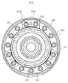
- FIG. 1 is an enlarged view of the movable side blocking section 100 in FIG.
- a movable arc contact 105 is provided at the center of the tip of the puffer cylinder 104.
- An insulating cover 106, an insulating nozzle 101, and a movable main contact 102 are concentrically arranged around the outer periphery of the movable arc contact 105 so as to surround it.
- the puffer cylinder 104 has a cylindrical end projecting (hereinafter referred to as a cylindrical portion 104 a), and a movable main contact 102 is attached to a plurality of movable main contact fixing bolts 108 ( (See FIG. 5).
- the movable-side main contact 102 is hollow, and the presser fitting fixing bolt 107 and the movable-side main contact fixing bolt 108 are fixed in the hollow portion.
- the distal end of the movable side main contact 102 on the side of the blocking part is formed of a curved movable side main contact shield part 102b having a curved shape in order to relax the electric field.
- a fastening hole 107a for fastening a later-described presser fitting adjusting hole 102a, a presser fitting fixing bolt 107, and a movable side main contact fixing bolt 108 are fastened.
- the fastening hole 108a is provided (see FIG. 8).
- the insulating nozzle 101 is fitted into the cylindrical portion 104a, and the insulating nozzle screw portion 101a is screwed into the cylindrical portion 104a.
- the insulating nozzle 101 has an insulating nozzle large-diameter portion 101b at a position facing the distal end portion (blocking portion side end portion) of the cylindrical portion 104a.
- the insulating nozzle large-diameter portion 101b is fitted with a slight gap between the inner surface of the cylindrical portion 104a of the puffer cylinder 104 in consideration of thermal expansion when an arc is generated.
- the presser fitting 103 and the movable side main contact 102 are fastened together by a presser fixture fixing bolt 107 (see FIG. 5). Thereby, as shown in FIG. 1, the insulating nozzle large-diameter portion 101 b is locked by the presser fitting 103 and fixed to the inner peripheral surface of the cylindrical portion 104 a of the puffer cylinder 104.
- FIG. 3 shows an example of the presser fitting 103.
- the locking portion 103 c that locks the insulating nozzle large-diameter portion 101 b of the insulating nozzle 101 has a curved shape with substantially the same curvature as the outer periphery of the insulating nozzle 101.
- a presser fitting positioning hole 103a is provided at substantially the center of the presser fitting 103, and a screw fixing long hole 103b is provided at both ends thereof.
- the screwing long hole 103b is a long hole whose adjustment position can be adjusted in the radial direction of the insulating nozzle 101 when the presser fitting 103 is fixed to the insulating nozzle 101 in the hollow portion of the movable main contact 102. It has become.
- the presser fitting 103 is made of a high strength steel material.
- a plurality of presser fittings 103 are provided along the outer periphery of the insulating nozzle 101 so as to have sufficient strength in accordance with the size of the blocking portion.
- FIG. 7 a configuration in which the presser fittings 103 are provided at three positions at equal intervals is conceivable.
- the movable main contact 102 is fixed to the distal end of the cylindrical portion 104a with fixing bolts 108 (see FIGS. 1 and 5), and the insulating nozzle 101 is screwed into the inner peripheral surface of the cylindrical portion 104a to hold the presser fitting 103. Temporarily fasten with the presser fitting fixing bolt 107 (see FIG. 5).
- FIGS. 4 and 5 show the state before the presser fitting 103 is locked to the insulating nozzle large diameter portion 101b of the insulating nozzle 101
- FIGS. 6 and 7 show the state after the locking.
- a plurality of presser fitting adjustment holes 102 a are provided at the distal end of the movable main contact 102 on the blocking portion side.
- the presser fitting positioning jig 401 is inserted into the presser fitting positioning hole 103a through the presser fitting adjusting hole 102a.
- FIG. 5 shows a state in which the AA cross section of FIG. 4 is viewed from the blocking part side.
- the presser fitting fixing bolt 107 is temporarily fixed, and the position of the presser fitting 103 can be adjusted along the longitudinal direction of the screw fixing elongated hole 103b.
- the position of the presser fitting 103 is shifted using the presser fitting adjusting hole 102 a as a fulcrum so that the locking portion 103 c of the presser fitting 103 contacts the outer periphery of the insulating nozzle 101.
- the presser fitting fixing bolt 107 is fastened with the insulating nozzle large-diameter portion 101b locked.
- the clamp 107 for fixing the presser fitting can be fastened from the gap between the insulating nozzle 101 and the movable main contact 102.
- the movable main contact shield part will be described later. It is preferable to provide a plurality of fastening holes 107a (see FIG. 8) for fastening the presser fitting fixing bolts 107 to the 102b, and to fasten the bolts 107 through the holes.
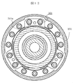
- FIG. 8 is a cross-sectional view taken along the line CC of FIG. 6, and is a view of the front side of the movable main contact 102 from the blocking portion side.
- a plurality of fastening holes 108a for fastening the movable main contact fixing bolts 108 from the blocking portion side are provided in the front surface of the movable main contact 102 in the circumferential direction of the movable main contact.
- the presser fitting adjustment holes 102a as the presser fittings 103 are provided, and the fastening holes 107a for fastening the presser fitting fixing bolts 107 from the blocking portion side are provided on both sides of the presser fitting adjustment holes 102a.
- the presser fitting 103 is fixed inside the movable-side main contact shield part 102b, and most of it is hidden by the shield part 102b, so that only the end part on the locking part 103c side can be seen.
- the movable side main contact fixing bolt 108 is drawn so that it can be seen from the fastening hole 108a, and the presser fitting fixing bolt 107 is seen from the fastening hole 107a.
- the movable side main contact fixing bolt 108 and the presser fitting fixing bolt 107 are fixed in the hollow portion of the movable side main contact 102 (see FIG. 1).
- the holding metal fitting fixing bolt 107 and the movable side main contact fixing bolt 108 are arranged inside the movable side main contact shield part 102b, these bolts are weak in electric field. There is no fear of becoming a part, and it can contribute to the improvement of reliability.
- the risk of dropping off the insulating nozzle is remarkably reduced as compared with the conventional configuration fixed only by screwing, and the reliability is improved. Leads to.
- the insulating nozzle 101 When replacing the insulating nozzle 101 for maintenance of the blocking part, the insulating nozzle 101 can be removed and a new insulating nozzle 101 can be attached by performing the reverse of the above procedure.
- the movable main contact 102 is fixed to the cylindrical portion 104a at the tip of the puffer cylinder 104 by a movable main contact fixing bolt 108. For this reason, even if the presser fitting fixing bolt 107 is removed when replacing the insulating nozzle 101 during maintenance work, the movable side main contact fixing bolt 108 remains fixed, so that the movable side main contact 102 can be fixed. There is no influence, and misalignment of the blocking portion (shift of the central axis between the movable main contact and the fixed main contact) can be prevented.
- the movable main contact 102 may be configured as shown in FIG. This is a configuration in which the portion of the movable main contactor 102 to which the presser fitting 103 is fastened is cut out so that the presser fitting 103 fits into that portion.
- the insulating nozzle 101 can be locked while the presser fitting 103 is directly fastened to the cylindrical portion 104a of the puffer cylinder 104 as shown in FIG.
- the movable main contact 102 generally composed mainly of a chrome copper alloy can be reduced in weight, and the weight on the movable side can be reduced, thereby contributing to an improvement in the breaking speed.
- Example 2 will be described with reference to FIGS.
- the same parts as those in the first embodiment are denoted by the same reference numerals and the description thereof is omitted.
- the present embodiment is characterized in that the presser fitting 501 shown in FIG. 11 is applied in place of the presser fitting 103 of the first embodiment.
- the presser fitting 501 has an arcuate portion 501a projecting along the outer peripheral direction of the nozzle at a portion where the nozzle large-diameter portion 101b is locked.
- FIG. 12 shows the configuration after the presser fitting 501 is attached.
- Example 3 will be described with reference to FIG.
- the same parts as those in the first embodiment are denoted by the same reference numerals and the description thereof is omitted.
- the insulating nozzle 101 is screwed and fixed to the inner peripheral surface of the cylindrical portion 104a of the puffer cylinder 104, whereas in this embodiment, the insulating nozzle 101 is screwed and fixed to the inner peripheral surface of the movable side main contact 602.
- the movable contact 602 is fixed to the end of the puffer cylinder 604 on the side of the interrupting portion together with the presser fitting 103 by the presser fitting fixing bolt 107 (a bolt longer than that of the first embodiment).
- the other points are the same as in the first embodiment, and the procedure of the attaching / detaching work is also the same. This eliminates the need to provide a cylindrical portion at the end of the puffer cylinder on the shut-off portion side, so that there is a merit that machining is facilitated.
- presser fitting 501 having the configuration shown in the second embodiment can also be applied to the third embodiment.
Landscapes
- Circuit Breakers (AREA)
Abstract
Priority Applications (4)
| Application Number | Priority Date | Filing Date | Title |
|---|---|---|---|
| KR1020157010493A KR101777251B1 (ko) | 2013-03-08 | 2014-02-03 | 가스 차단기 |
| CN201480007321.2A CN104981886B (zh) | 2013-03-08 | 2014-02-03 | 气体断路器 |
| US14/768,691 US9543095B2 (en) | 2013-03-08 | 2014-02-03 | Gas circuit breaker |
| JP2015504205A JP5936766B2 (ja) | 2013-03-08 | 2014-02-03 | ガス遮断器 |
Applications Claiming Priority (2)
| Application Number | Priority Date | Filing Date | Title |
|---|---|---|---|
| JP2013046093 | 2013-03-08 | ||
| JP2013-046093 | 2013-03-08 |
Publications (1)
| Publication Number | Publication Date |
|---|---|
| WO2014136513A1 true WO2014136513A1 (fr) | 2014-09-12 |
Family
ID=51491039
Family Applications (1)
| Application Number | Title | Priority Date | Filing Date |
|---|---|---|---|
| PCT/JP2014/052388 WO2014136513A1 (fr) | 2013-03-08 | 2014-02-03 | Disjoncteur à gaz comprimé |
Country Status (6)
| Country | Link |
|---|---|
| US (1) | US9543095B2 (fr) |
| JP (1) | JP5936766B2 (fr) |
| KR (1) | KR101777251B1 (fr) |
| CN (1) | CN104981886B (fr) |
| TW (1) | TW201442051A (fr) |
| WO (1) | WO2014136513A1 (fr) |
Cited By (1)
| Publication number | Priority date | Publication date | Assignee | Title |
|---|---|---|---|---|
| WO2019150655A1 (fr) * | 2018-02-02 | 2019-08-08 | 株式会社東芝 | Disjoncteur à gaz |
Families Citing this family (7)
| Publication number | Priority date | Publication date | Assignee | Title |
|---|---|---|---|---|
| CN107787516B (zh) * | 2015-04-13 | 2020-06-19 | Abb瑞士股份有限公司 | 仅中断非短路电流的装置、尤其是隔离开关或接地开关 |
| RU168757U1 (ru) * | 2016-05-31 | 2017-02-17 | Акционерное общество "Научно-исследовательский и проектно-конструкторский институт высоковольтного аппаратостроения (АО "НИИВА") | Высоковольтный баковый выключатель с газовой изоляцией |
| EP3561840A4 (fr) * | 2016-12-16 | 2020-08-19 | Toshiba Energy Systems & Solutions Corporation | Dispositif de commutation à isolation gazeuse |
| EP3407370B1 (fr) * | 2017-05-24 | 2020-04-01 | General Electric Technology GmbH | Interrupteur à gaz comprimé comprenant une chambre de stockage de gaz optimisée |
| EP3618088A1 (fr) * | 2018-08-30 | 2020-03-04 | ABB Schweiz AG | Buse pour disjoncteur haute ou moyenne tension |
| CN109935495B (zh) * | 2018-11-09 | 2024-04-30 | 许继(厦门)智能电力设备股份有限公司 | 一种灭弧室绝缘辅助结构 |
| US10734175B1 (en) * | 2019-09-24 | 2020-08-04 | Southern States Llc | High voltage electric power switch with anti-flashover nozzle |
Citations (5)
| Publication number | Priority date | Publication date | Assignee | Title |
|---|---|---|---|---|
| JPH0463523U (fr) * | 1990-10-11 | 1992-05-29 | ||
| JPH08111151A (ja) * | 1994-10-12 | 1996-04-30 | Hitachi Ltd | パッファ式ガス遮断器 |
| JPH0997543A (ja) * | 1995-09-29 | 1997-04-08 | Fuji Electric Co Ltd | パッファ形ガス遮断器 |
| JP2000509544A (ja) * | 1996-04-22 | 2000-07-25 | シーメンス アクチエンゲゼルシヤフト | 高電圧用遮断器の遮断部 |
| JP2008529223A (ja) * | 2005-02-01 | 2008-07-31 | アーベーベー・テヒノロギー・アーゲー | 電気的スイッチング装置のためのノズルの固定 |
Family Cites Families (9)
| Publication number | Priority date | Publication date | Assignee | Title |
|---|---|---|---|---|
| JP2523675B2 (ja) * | 1987-08-31 | 1996-08-14 | 株式会社日立製作所 | パツフア式ガス遮断器 |
| JPH01243328A (ja) * | 1988-03-25 | 1989-09-28 | Hitachi Ltd | パツフア式ガス遮断器 |
| FR2711269B1 (fr) * | 1993-10-12 | 1995-12-29 | Gec Alsthom T & D Sa | Disjoncteur à haute tension capable de couper des courants de défaut à passage par zéro retardé. |
| WO1995027299A1 (fr) * | 1994-04-05 | 1995-10-12 | Abb Power T & D Company Inc. | Plaque mobile de melange de gaz destinee a un rupteur a souffleur |
| JPH103834A (ja) | 1996-06-14 | 1998-01-06 | Hitachi Ltd | パッファ式ガス遮断器 |
| DE19738697C1 (de) * | 1997-08-29 | 1998-11-26 | Siemens Ag | Hochspannungsleistungsschalter mit antreibbarem Gegenkontaktstück |
| CN1420515A (zh) * | 2001-11-21 | 2003-05-28 | 株式会社日立制作所 | 缓冲型气体断路器 |
| US6696657B2 (en) | 2001-11-21 | 2004-02-24 | Hitachi, Ltd. | Puffer type gas circuit breaker |
| JP2008123761A (ja) * | 2006-11-09 | 2008-05-29 | Toshiba Corp | ガス遮断器 |
-
2013
- 2013-12-17 TW TW102146646A patent/TW201442051A/zh unknown
-
2014
- 2014-02-03 JP JP2015504205A patent/JP5936766B2/ja active Active
- 2014-02-03 KR KR1020157010493A patent/KR101777251B1/ko active IP Right Grant
- 2014-02-03 US US14/768,691 patent/US9543095B2/en active Active
- 2014-02-03 CN CN201480007321.2A patent/CN104981886B/zh active Active
- 2014-02-03 WO PCT/JP2014/052388 patent/WO2014136513A1/fr active Application Filing
Patent Citations (5)
| Publication number | Priority date | Publication date | Assignee | Title |
|---|---|---|---|---|
| JPH0463523U (fr) * | 1990-10-11 | 1992-05-29 | ||
| JPH08111151A (ja) * | 1994-10-12 | 1996-04-30 | Hitachi Ltd | パッファ式ガス遮断器 |
| JPH0997543A (ja) * | 1995-09-29 | 1997-04-08 | Fuji Electric Co Ltd | パッファ形ガス遮断器 |
| JP2000509544A (ja) * | 1996-04-22 | 2000-07-25 | シーメンス アクチエンゲゼルシヤフト | 高電圧用遮断器の遮断部 |
| JP2008529223A (ja) * | 2005-02-01 | 2008-07-31 | アーベーベー・テヒノロギー・アーゲー | 電気的スイッチング装置のためのノズルの固定 |
Cited By (2)
| Publication number | Priority date | Publication date | Assignee | Title |
|---|---|---|---|---|
| WO2019150655A1 (fr) * | 2018-02-02 | 2019-08-08 | 株式会社東芝 | Disjoncteur à gaz |
| JPWO2019150655A1 (ja) * | 2018-02-02 | 2021-01-07 | 株式会社東芝 | ガス遮断器 |
Also Published As
| Publication number | Publication date |
|---|---|
| JPWO2014136513A1 (ja) | 2017-02-09 |
| CN104981886A (zh) | 2015-10-14 |
| US20160005559A1 (en) | 2016-01-07 |
| JP5936766B2 (ja) | 2016-06-22 |
| US9543095B2 (en) | 2017-01-10 |
| KR20150060861A (ko) | 2015-06-03 |
| TW201442051A (zh) | 2014-11-01 |
| KR101777251B1 (ko) | 2017-09-11 |
| CN104981886B (zh) | 2017-02-08 |
Similar Documents
| Publication | Publication Date | Title |
|---|---|---|
| JP5936766B2 (ja) | ガス遮断器 | |
| KR101423142B1 (ko) | 버퍼형 가스 차단기 | |
| JP2009525569A (ja) | ガス絶縁高圧スイッチのためのスイッチングチャンバ | |
| US6660954B2 (en) | Gas-blast circuit-breaker | |
| US20120061352A1 (en) | Gas-insulated switchgear | |
| US9704679B2 (en) | Gas circuit breaker | |
| KR102525553B1 (ko) | 초고압 차단기 | |
| KR101013723B1 (ko) | 가스절연 차단기의 극간 전계완화장치 | |
| KR101460299B1 (ko) | 가스배출안내부를 적용한 가스절연차단기 | |
| JP4131926B2 (ja) | ガス遮断器 | |
| JP2002319341A (ja) | 真空バルブ | |
| JP5440485B2 (ja) | パッファ形ガス遮断器 | |
| US10049839B2 (en) | Gas circuit breaker | |
| JP4869867B2 (ja) | ガス絶縁遮断器 | |
| JP5143677B2 (ja) | パッファ形ガス遮断器 | |
| KR101276945B1 (ko) | 가스 차단기용 퍼퍼 실린더 조립체 | |
| KR102070140B1 (ko) | 소형 저압용 차단기의 아크런너 설치구조 | |
| EP3588528B1 (fr) | Disjoncteur haute ou moyenne tension isolé au gaz comportant un élément de type anneau | |
| JP2010061858A (ja) | ガス遮断器 | |
| JPH031415A (ja) | アーク・スピナ・インタラプタ | |
| WO2020003854A1 (fr) | Disjoncteur à gaz | |
| EP3618088A1 (fr) | Buse pour disjoncteur haute ou moyenne tension | |
| JP2005532662A (ja) | 電気設備のためのアーク接触子およびその製造方法ならびに接触アセンブリさらに対応した電気設備 | |
| KR20100079346A (ko) | 가스 절연 개폐장치의 절연서포트 | |
| KR20200117421A (ko) | 가스절연개폐장치의 차단기 |
Legal Events
| Date | Code | Title | Description |
|---|---|---|---|
| 121 | Ep: the epo has been informed by wipo that ep was designated in this application |
Ref document number: 14760997 Country of ref document: EP Kind code of ref document: A1 |
|
| ENP | Entry into the national phase |
Ref document number: 2015504205 Country of ref document: JP Kind code of ref document: A |
|
| ENP | Entry into the national phase |
Ref document number: 20157010493 Country of ref document: KR Kind code of ref document: A |
|
| WWE | Wipo information: entry into national phase |
Ref document number: 14768691 Country of ref document: US |
|
| WWE | Wipo information: entry into national phase |
Ref document number: IDP00201505074 Country of ref document: ID |
|
| NENP | Non-entry into the national phase |
Ref country code: DE |
|
| 122 | Ep: pct application non-entry in european phase |
Ref document number: 14760997 Country of ref document: EP Kind code of ref document: A1 |