WO2014136249A1 - 無線伝送システム - Google Patents
無線伝送システム Download PDFInfo
- Publication number
- WO2014136249A1 WO2014136249A1 PCT/JP2013/056383 JP2013056383W WO2014136249A1 WO 2014136249 A1 WO2014136249 A1 WO 2014136249A1 JP 2013056383 W JP2013056383 W JP 2013056383W WO 2014136249 A1 WO2014136249 A1 WO 2014136249A1
- Authority
- WO
- WIPO (PCT)
- Prior art keywords
- relay station
- base station
- station
- polling
- hierarchy
- Prior art date
- Legal status (The legal status is an assumption and is not a legal conclusion. Google has not performed a legal analysis and makes no representation as to the accuracy of the status listed.)
- Ceased
Links
Images











Classifications
-
- H—ELECTRICITY
- H04—ELECTRIC COMMUNICATION TECHNIQUE
- H04W—WIRELESS COMMUNICATION NETWORKS
- H04W74/00—Wireless channel access
- H04W74/04—Scheduled access
- H04W74/06—Scheduled access using polling
-
- H—ELECTRICITY
- H04—ELECTRIC COMMUNICATION TECHNIQUE
- H04B—TRANSMISSION
- H04B7/00—Radio transmission systems, i.e. using radiation field
- H04B7/14—Relay systems
-
- H—ELECTRICITY
- H04—ELECTRIC COMMUNICATION TECHNIQUE
- H04L—TRANSMISSION OF DIGITAL INFORMATION, e.g. TELEGRAPHIC COMMUNICATION
- H04L45/00—Routing or path finding of packets in data switching networks
- H04L45/74—Address processing for routing
- H04L45/745—Address table lookup; Address filtering
-
- H—ELECTRICITY
- H04—ELECTRIC COMMUNICATION TECHNIQUE
- H04W—WIRELESS COMMUNICATION NETWORKS
- H04W28/00—Network traffic management; Network resource management
- H04W28/16—Central resource management; Negotiation of resources or communication parameters, e.g. negotiating bandwidth or QoS [Quality of Service]
- H04W28/18—Negotiating wireless communication parameters
- H04W28/20—Negotiating bandwidth
-
- H—ELECTRICITY
- H04—ELECTRIC COMMUNICATION TECHNIQUE
- H04B—TRANSMISSION
- H04B7/00—Radio transmission systems, i.e. using radiation field
- H04B7/14—Relay systems
- H04B7/15—Active relay systems
- H04B7/155—Ground-based stations
-
- H—ELECTRICITY
- H04—ELECTRIC COMMUNICATION TECHNIQUE
- H04B—TRANSMISSION
- H04B7/00—Radio transmission systems, i.e. using radiation field
- H04B7/24—Radio transmission systems, i.e. using radiation field for communication between two or more posts
- H04B7/26—Radio transmission systems, i.e. using radiation field for communication between two or more posts at least one of which is mobile
- H04B7/2643—Radio transmission systems, i.e. using radiation field for communication between two or more posts at least one of which is mobile using time-division multiple access [TDMA]
- H04B7/2656—Radio transmission systems, i.e. using radiation field for communication between two or more posts at least one of which is mobile using time-division multiple access [TDMA] for structure of frame, burst
-
- H—ELECTRICITY
- H04—ELECTRIC COMMUNICATION TECHNIQUE
- H04L—TRANSMISSION OF DIGITAL INFORMATION, e.g. TELEGRAPHIC COMMUNICATION
- H04L45/00—Routing or path finding of packets in data switching networks
- H04L45/02—Topology update or discovery
- H04L45/021—Ensuring consistency of routing table updates, e.g. by using epoch numbers
-
- H—ELECTRICITY
- H04—ELECTRIC COMMUNICATION TECHNIQUE
- H04W—WIRELESS COMMUNICATION NETWORKS
- H04W72/00—Local resource management
- H04W72/04—Wireless resource allocation
- H04W72/044—Wireless resource allocation based on the type of the allocated resource
- H04W72/0446—Resources in time domain, e.g. slots or frames
-
- H—ELECTRICITY
- H04—ELECTRIC COMMUNICATION TECHNIQUE
- H04W—WIRELESS COMMUNICATION NETWORKS
- H04W84/00—Network topologies
- H04W84/18—Self-organising networks, e.g. ad-hoc networks or sensor networks
-
- H—ELECTRICITY
- H04—ELECTRIC COMMUNICATION TECHNIQUE
- H04W—WIRELESS COMMUNICATION NETWORKS
- H04W88/00—Devices specially adapted for wireless communication networks, e.g. terminals, base stations or access point devices
- H04W88/02—Terminal devices
-
- H—ELECTRICITY
- H04—ELECTRIC COMMUNICATION TECHNIQUE
- H04W—WIRELESS COMMUNICATION NETWORKS
- H04W88/00—Devices specially adapted for wireless communication networks, e.g. terminals, base stations or access point devices
- H04W88/08—Access point devices
Definitions
- the present invention relates to a radio transmission system, and more particularly to radio communication, and more particularly to a multi-hop radio communication system.
- Patent Document 1 discloses a system that uses an IEEE802.11e extended MAC (Media Access Control).
- DCF Distributed Coordination Access
- PCF Point Coordination Channel Access
- EDCA Enhanced Distributed Channel Access
- QoS Quality of Service
- HCCA HybridledCorndledCorrectedCorndledCorrectedCorndledCorrectedCordedCordinaryCouldedCorrectedCord
- the above-mentioned DCF and EDCA are based on CSMA (Carrier Sense Multiple Access), and provide contention access means to the terminal.
- PCF and HCCA are polling access methods, and provide non-contention access means for terminals.
- the IEEE 802.11e standard document discloses a reference scheduling method using HCCA.
- Patent Document 2 or Patent Document 3 describes a method for securing QoS using polling.
- Patent Document 2 discloses a method for changing the frequency channel at each hop so that communication with an upper radio station and communication with a lower radio station can be simultaneously performed by polling control.
- Patent Document 3 discloses a method of passing a polling right to a lower relay station like a bucket relay. In the case of this method, if the polling packet has a communication error, it is impossible to poll lower relay stations and terminals after that. Thus, since the loss of the polling packet affects the entire system, it is difficult to ensure robustness.
- the present invention provides a polling-based multi-hop communication system capable of realizing robust communication by constructing multi-hops with the same frequency channel in order to simplify hardware and save frequency channels.
- a first means for solving the above problem is configured as a radio station having a base station, a plurality of relay stations, and a plurality of terminals, and the terminal and the relay station are the base station or the relay station multistage.
- a wireless transmission system that is wirelessly connected in a hierarchical manner, wherein the base station and the relay station are synchronized, and the system cycle of the base station and the relay station is the same in time,
- the base station and the relay station are allotted one or more service periods within one system synchronization and in a time division manner, and within one service period, the base station or the relay station Polling communication by polling is performed with the terminal registered in the local station, and in the polling communication, a polling packet is transmitted from the base station or the relay station to the terminal registered in the local station.
- Sending And the base station or the relay station receives a response signal from the terminal the registered in the own station.
- the base station transfers a synchronization packet to a first relay station that is lower in the hierarchy than the base station, and the first relay station that has received the synchronization packet receives a first packet that is lower in the hierarchy than the first relay station.
- the synchronization packet is transferred to two relay stations, and the base station and the first and second relay stations determine the service period assigned based on the transmission timing of the synchronization packet.
- the service period is managed with at least three parameters of a start time of the service period, a stop time of the service period, and an overall system cycle based on the transmission timing of the synchronization packet.
- the service period includes a polling period and a CSMA period.
- the polling period for performing the polling communication the base station or the relay station to which the service period is allocated is wirelessly connected, and QoS communication is performed. Polling is performed on the necessary terminal, and the polling communication is not performed or other communication is performed in the CSMA section.
- the polling period is a comprehensive polling period in which the polling is performed for all the terminals wirelessly connected to the base station or the relay station, and data transmission fails within the period of the comprehensive polling period.
- a selective polling period in which the terminal performs polling until data transmission from the base station or the relay station is successful.
- the service period is assigned to the same base station or relay station more than once during the system cycle, the first service period is composed of a comprehensive polling period, and the second service period is at least selected. Configured with a dynamic polling interval.
- first relay station in the first hierarchy and a second relay station in the second hierarchy that is lower than the first relay station, and the second relay station, the first relay station, and the base station in this order.
- the service periods are sequentially assigned in order from the top of the system period in time.
- the base station and the relay station include synchronization reference point information in the synchronization packet
- the second relay station that receives the synchronization packet is an internal clock with the base station or the first relay station.
- the accurate time of the reference point is obtained from the reference point information and the counter difference of the internal clock.
- the base station and the relay station to which the service period is allocated transmit an end notification packet at the end of the service period, and the end notification packet includes the base station to which the next service period is allocated or Transmission prohibition time information based on the polling interval length of the polling communication of the relay station is included.
- the relay station holds a table holding routing information
- the relay station receives an association request from a terminal not connected to the relay station, and the terminal information is added to the terminal information of the routing table.
- the routing table change information is wirelessly transferred to a base station higher in the hierarchy than the relay station or another relay station higher in the hierarchy, receives a bandwidth request from the terminal, and sends the bandwidth request from the terminal. Is wirelessly transferred to a base station higher in the hierarchy or a relay station higher in the hierarchy than the terminal.
- the relay station receives routing table change information from a relay station lower in hierarchy than the relay station, updates the routing table based on the change information, and is transferred from the relay station in lower hierarchy.
- the bandwidth request information is transferred to the base station higher in the hierarchy than the relay station lower in the hierarchy or the relay station higher in hierarchy than the relay station lower in the hierarchy.
- the base station receives routing table change information from the lower hierarchy relay station, updates the routing table based on the change information, and the base station transfers from the lower hierarchy relay station
- the received bandwidth request is received, resource calculation is performed in response to the request, and a packet including request permission information or non-permission information and service period allocation change information is transmitted to the lower relay station based on the calculation result .
- the connected terminal performs blockage detection of the connected terminal, and when blockage is confirmed, updates the terminal information in the routing table and transfers the change information of the routing table to a base station or relay station higher in the hierarchy. Then, the bandwidth request is transferred to the base station or relay station higher in the hierarchy.
- the relay station receives routing table change information from a relay station lower in the hierarchy, updates the routing table based on the change information, and the relay station is different from the relay station in the lower hierarchy.
- the relay station receives the bandwidth request transferred from the relay station, and forwards it to a base station that is higher in the hierarchy than the relay station or a separate relay station that is higher in the hierarchy than the relay station.
- the base station receives routing table change information from the relay station lower in hierarchy than the base station, updates the routing table based on the change information, and the base station
- the bandwidth request transferred from the relay station is received, resource calculation is performed in response to the request, and a packet including request permission and service period allocation change information is transmitted to the lower relay station based on the calculation result .
- a constant band and low-delay communication is possible in multi-hop transmission, and a wireless transmission system that is robust against interference can be provided.
- multi-hop can be configured with the same frequency channel, hardware can be simplified and frequency resources can be saved.
- 2 is a network configuration example according to the first embodiment. It is an example of a polling operation
- 4 is a time chart illustrating a first polling timing example in the first embodiment.
- 6 is a time chart illustrating a second polling timing example according to the first exemplary embodiment.
- 6 is a time chart illustrating a third example of polling timing in the first embodiment.
- 6 is a time chart illustrating a fourth polling timing example according to the first exemplary embodiment.
- 3 is a timing chart illustrating an operation example of a base station in a first polling timing example in Embodiment 1.
- 6 is a timing chart illustrating an operation example of a relay station in a first polling timing example in Embodiment 1.
- FIG. 3 is a chart illustrating operations of a base station and a relay station in the first embodiment.
- 3 is a flowchart illustrating an operation of the base station in the first embodiment.
- 3 is a flowchart illustrating an operation of the relay station in the first embodiment.
- 3 is a block diagram illustrating a configuration example of a base station in Embodiment 1.
- FIG. 6 is a time chart illustrating a fifth polling timing example according to the first exemplary embodiment. It is a time chart which shows the coping method when transmission is overdue when a synchronous packet has interference. It is a figure which shows the countermeasure against interference using transmission prohibition. It is a block diagram which shows the structural example of the base station in 2nd Embodiment.
- 1 is a wireless monitoring camera system that is an application example 1 of the present invention. It is the remote control system which is the application example 2 of this invention.
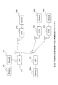
- FIG. 1 is a schematic diagram illustrating a network configuration example of a wireless transmission system according to the first embodiment.
- the network includes a base station (AP) 01, one or more relay stations, and one or more terminals (devices) (STA) 04a to e.
- the base station, the relay station, and the terminal are wireless stations that perform wireless communication.
- an example will be described that includes three relay stations and a plurality of terminals connected to them.
- the relay station has a multi-level layer structure with the base station as a route.
- the relay station a (RPa) 02a and relay station b (RPb) 02b are connected to the base station.
- the relay station aa (RPa-a) 03a and the relay station ab (RPa-b) 03b are relay stations connected to the relay station a02a.
- data transmitted from the terminal 04a is transmitted to the base station 01 via the relay station a-a03a and the relay station a02a.
- data is transmitted from the base station 01 to the terminal 04a through the relay station a02a and the relay station a-a03a.
- the base station or the relay station is connected to each other, and performs polling control for a radio station that requests QoS communication (hereinafter referred to as QoS radio station).
- the polling control is performed for each time unit called a service period (SI: Service Interval).
- FIG. 2 shows an example of polling operation during the service period.
- the base station or the relay station transmits a polling packet, and the QoS wireless stations (terminal 1 and terminal 2) connected to the base station or relay station are allowed to transmit data only when a polling packet addressed to itself is received.
- Service period is divided into polling period and CSMA period.
- polling interval the base station or relay station repeats polling packet transmission, data reception, and, in some cases, ACK transmission operations.
- CSMA section no polling packet is transmitted.
- a CSMA End packet that notifies the end of the CSMA section to other radio stations may be transmitted.
- the polling period is classified into a comprehensive polling period and a selective polling period.
- the base station or the relay station transmits a polling packet to all the connected QoS radio stations.
- the selective polling period a polling packet is transmitted to the QoS wireless station that failed to transmit data in the comprehensive polling period, and this is performed until the data transmission is successful.
- This control makes it possible to achieve transmission with a definite delay even when an error occurs in communication.
- the service period during which polling can be performed by the base station and the relay station is the period of the system (system period ) Are allocated to each in a time-sharing manner.
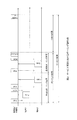
- FIG. 3 shows the (first) timing example.
- the network is not a network configuration in FIG. 1 but a network in which the base station, the relay station 1, and the relay station 2 are configured in a multi-hop order. (Even if the description here is extended to the network of FIG. 1, the gist of the present invention described here is not lost.)
- service periods are assigned in the order of the relay station 2, the relay station 1, and the base station in the lower order of the multi-hop network, that is, the relay station 2, the relay station 1, and the base station.
- the service period is composed of a polling period and a CSMA period as described above.
- the base station, the relay station 1 and the relay station 2 need to be synchronized. This synchronization is performed by transmitting a synchronization packet from the base station to the relay station 1, and the relay station 1 further transmits a synchronization packet to the relay station 2.
- the service period is determined based on the transmission / reception timing of these synchronization packets as a reference time base.
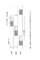
- FIG. 4 shows a second polling timing example, and shows that the polling interval is composed of a comprehensive polling interval and a selective polling interval with respect to the first timing example.
- the service period to be assigned is one section that is continuous, but it is also possible to divide and assign in units of the above sections.
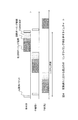
- FIG. 5 shows a third timing example showing an example thereof.
- a comprehensive polling interval is assigned in the order of relay station 2, relay station 1, and base station, and then a selective polling interval and a CSMA interval are assigned in order.
- this timing example shows an example of transmitting an end notification (CSMA End) packet at the end of the CSMA section.
- CSMA End end notification
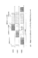
- FIG. 6 shows a fourth timing example.
- a polling section composed of a comprehensive polling section and a selective polling section is sequentially assigned to the relay station 2, the relay station 1, and the base station, and then the CSMA section is assigned as a whole.
- a polling interval end notification packet is transmitted at the end of the interval.
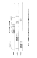
- FIG. 7 shows an example of timing control in the base station 01 in the network configuration in FIG. 1 and the first polling timing control example in FIG.
- Timing control is performed using at least three of a system cycle (SIsystem), a service period start time (SIstart), and a service period stop time (SIstop).
- SIsystem system cycle
- SIstart service period start time
- SIstop service period stop time
- the synchronization packet is transmitted to the relay station (relay station a02a, relay station b02b) at the lower level of the hierarchy at the beginning of the system cycle.
- FIG. 8 similarly shows the timing control of the relay station.
- FIG. 8 shows an example of control in the relay station a02a in the network configuration of FIG. Based on the synchronization timing transmitted from the base station 01, the head of the system period is determined to control the service period.
- the relay station a02a When receiving the synchronization packet sent to the relay station, the relay station a02a transmits the synchronization packet to the relay station (relay station a-a03a or relay station a-b03b) lower in the hierarchy of the own station.
- FIG. 9 An example of operation in the base station 01 and the relay stations 02 and 03 will be described using the flowcharts of FIGS. 9 (a), 9 (b), and 10.
- FIG. 9 (a), 9 (b), and 10 An example of operation in the base station 01 and the relay stations 02 and 03 will be described using the flowcharts of FIGS. 9 (a), 9 (b), and 10.
- FIG. 9 (a) is a chart showing operations in the base station and the relay station. After initialization, the system enters an idle state and waits for various interrupts. After an interrupt occurs, processing is performed after the cause of the interrupt. Each interrupt process will be described with reference to FIG. 9B and FIG.
- FIG. 9A shows an operation example when a timer for managing the system cycle is input in the base station.
- the network is not a multi-hop network, and polling control having a service period as shown in the example of FIG. 2 is started. If there is a lower relay station, a synchronization packet is transmitted to at least one of the relay stations, and a service period start timer is set.
- FIG. 9B shows an operation example when the service period start timer is input. After inputting the service period start timer, a service period stop timer is set, and polling control having a service period as shown in the example of FIG. 2 is started.
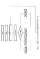
- FIG. 10A shows an operation example when the relay station receives a synchronization packet.
- a correct reference time is calculated from the reception timing, and a system period start time is determined. If the reception timing is later than the start time of the service period assigned to the own station, the synchronization packet is not transferred. This is because the polling communication starts when the start time starts, and the synchronization packet interferes.
- the synchronization packet is transmitted to at least one relay station.
- a service period start timer is set when there is no lower relay station or after sending a synchronization packet. If the system cycle timer is set, cancel it.
- FIG. 10B shows the operation after the service period start timer is input or after the system period timer is input. If the service period stop timer and the system period timer are not set after the input, the system is displayed. Set the periodic timer.
- the system period timer may be canceled and the service period may not be started thereafter. Thereafter, polling control having a service period as shown in the example of FIG. 2 is started.
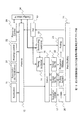
- FIG. 11 shows a configuration example of a base station and a relay station that enables the control described so far.
- the base station or relay station includes an application unit (Application) 11, a protocol processing unit (Protocol) 12, a reception processing unit (RX) 13, a timing control unit (Timing Controller) 14, a scheduling control unit (Scheduling Controller) 15, and data selection.
- Section 16 Select CSMA queue (Queue for CSMA) 17, Polling access queue (Queue for PA) 18, Piggyback queue (Queue for PB) 19, CSMA section (CSMA) 20, Polling access section (Polling Access) 21 , Piggyback access unit (Piggyback Access) 22, polling unit (Polling) 23, physical layer (P Y (TX / RX)), including the 24.
- the present invention is not limited by the implementation means such as a processor, FPGA, ASIC. That is, these functions may be realized as software on a processor, or may be realized as dedicated hardware as an ASIC.
- the protocol processing unit 12 When a data transmission request is generated from the application unit 11, the protocol processing unit 12 performs processing according to the communication specification.
- processing defined in IEEE 802.11 is performed.
- the selection unit 16 determines the type of data and determines which queue is used. As an example, in the case of data for which QoS is not required, since it is transmitted using normal CSMA, it is sent to the CSMA queue 17. When data that requires QoS is transmitted to a radio station higher in the hierarchy, the data is sent to the polling access queue 18. In addition, when QoS is required and transmission is performed to a radio station at a lower level, it is sent to the piggyback queue 19.
- Polling access transmits data by polling control from a radio station higher in the hierarchy
- piggyback access transmits data in a polling packet lower in the hierarchy.
- Each of the polling access unit 21 and the piggyback access unit 22 performs the processing.
- the timing control unit 14 performs the timing control as described above, and controls the system period, service period start time, and stop time in this embodiment. It also controls the transmission time of the synchronization packet.
- the scheduling control unit 15 controls scheduling within the service period.
- the polling packet is generated and transmitted by the polling unit 23.
- All packets are converted into actual radio signals by the physical layer 24 and transmitted to the space.
- FIG. 12 shows a fifth example of polling timing in this embodiment.
- Service period allocation is the same as that in FIG. 3, but a section dedicated to downlink communication is provided after the service period.
- one round-trip communication can be completed within a system cycle by assigning a service period for uplink communication from a relay station lower in the hierarchy and assigning a downlink communication from a base station / relay station higher in the hierarchy. it can.
- FIG. 13 shows an example of a method for determining the head of the system cycle.
- the base station and the relay station hold a counter for measuring time, and periodically measure the difference in counter value between the base station and the relay station.
- the measurement method is not particularly limited. For example, when IEEE802.11 is used, since the beacon signal is periodically transmitted, the beacon signal can be transmitted and received.
- the beacon signal is handled as a synchronization packet.
- the present embodiment shows a control method using a new synchronization packet.
- the base station transmits the synchronization value including the counter value of the start time (synchronization point) of the system cycle.
- the relay station that has received the synchronization packet can obtain the counter value of the synchronization point from the difference between the counter values measured in advance and the counter value included in the synchronization packet.
- the relay station transmits the calculated synchronization point counter value again in the synchronization packet.
- the correct synchronization point can be obtained even if the reception time of the synchronization packet is delayed due to the influence of the interference signal.
- a virtual carrier sense function is provided by using a mechanism called NAV (Network Allocation Vecotr), thereby enabling multiple access transmission control.
- NAV Network Allocation Vecotr
- FIG. 14 shows an example of a method for protecting data communication during polling control using this.
- the synchronization packet includes the time corresponding to the polling period of the service period immediately after as the period information, and the radio station that receives the synchronization packet is prohibited from transmitting during that period and the polling period is protected.
- an end notification packet including the time corresponding to the polling interval of the immediately subsequent service period as period information is transmitted.
- each polling packet and its reply packet are similarly transmitted including period information including the polling section time.
- the extension is also included.
- FIG. 14 when protecting a radio station that does not receive a radio signal from the relay station 2 and is within the range that can be reached from the relay station 1, an extension of the polling interval cannot be notified by a polling packet.
- the relay station 1 which is a station and including the extension period in the reply packet, it is possible to protect the polling section for the extension.
- FIG. 15 shows a configuration example of a base station / relay station having functions of terminal registration, polling resource allocation, and routing control.
- FIG. 16 shows an example of a flow when a terminal is added to or removed from the network realized in FIG.
- FIG. 17 shows a flowchart of an operation example in the terminal (a), the relay station (b), and the base station (c) when the terminal is added, and the terminal (a), the relay station (b), the base when the terminal leaves
- a flowchart of an operation example in the station (c) is shown in FIG.
- the terminal When adding a terminal, when the terminal is activated, it searches for nearby wireless stations, authenticates the appropriate base station or relay station as necessary, and sends an association request.
- a method of selecting a base station or relay station with the best RSSI can be considered.
- a bandwidth request for participation in polling control is transmitted.
- the bandwidth request includes, for example, a necessary bandwidth and an allowable delay amount as information. After that, when the bandwidth request permission is received, communication is started.
- the relay station that has received the association request returns an association permission. Thereafter, the routing table associating the IP address with the MAC address is updated, and the information is transmitted to the relay station or base station higher in the hierarchy.
- a bandwidth request When a bandwidth request is received from a terminal, it is transferred to a relay station or base station higher in the hierarchy, waits for reception of a bandwidth permission or rejection, and a bandwidth permission or rejection notification is forwarded to the terminal.
- the bandwidth permission When the bandwidth permission is received, the setting information including the service period timing information is sent at the same time, and the setting information is reflected in the service period parameter.
- the base station or relay station that has received the routing information updates the routing table based on the information.
- the base station that has received the bandwidth request performs resource calculation to determine whether or not bandwidth permission is possible. When it is impossible, a bandwidth rejection notification is transmitted. When possible, a bandwidth permission notification is transmitted together with setting information including new resource period information.
- This setting information is sent to all relay stations. Therefore, it is necessary for the relay station that has received this to transfer it to a relay station at a lower level. Thereafter, the base station reflects the change in the service period parameter.
- the connected relay station or base station detects it.
- the relay station that has detected that the connected terminal has left updates the routing table that associates the IP address with the MAC address, and transmits the information to the relay station or base station higher in the hierarchy.
- a bandwidth change request is transmitted to the base station, and a bandwidth change permission notification and setting information are received.
- the service period parameter is changed according to the received setting information.
- the base station or relay station that has received the routing information updates the routing table based on the information.
- the base station that has received the bandwidth change request performs resource calculation and transmits a bandwidth permission notification together with setting information including new resource period information.
- This information is sent to all relay stations. Therefore, it is necessary for the relay station that has received this information to be transferred to a relay station at a lower level. Then, the change is reflected in the service period parameter.
- the base station supervises control of wireless communication among base stations, relay stations, and terminals included in the system.
- routing control, resource control, and communication timing control related to wireless communication are managed and controlled in a base station.
- the present invention it is possible to provide a wireless transmission system that can perform constant band and low-delay communication in wireless multi-hop transmission and is robust against interference.
- multi-hops can be configured with the same frequency channel, hardware can be simplified and frequency resources can be saved.
- FIG. 19 shows simulation results of delay characteristics when multi-hop is realized by the conventional CSMA method and when it is realized by the proposed method.
- the physical layer used 54 Mbps of the IEEE802.11a standard in the data packet, the polling packet used 12 Mbps, the data was 3 Mbps, two terminals, and the number of hops was three. Thus, it can be seen that the proposed method has excellent delay characteristics.
- FIG. 20 shows an application of the wireless system of the present invention to a surveillance camera system.
- the base station (AP) 41, the relay station (RP) 42, and the terminal (STA) 43 are realized by the radio station in the present invention.
- a camera (Camera) 45 is connected to each terminal 43, and camera video is wirelessly transmitted via the terminal 43.
- Each terminal 43 is connected to the base station 41 or the relay station 42 and is transmitted by polling access controlled by either one.
- the relay station 42 transmits the received video data to the base station 41 by polling access.
- the camera 45 may be connected to the relay station 42 or the base station.
- a camera 45 a is connected to the relay station 42.
- a monitor 46 and a storage device 47 are connected to the base station 31 for display and recording. According to this application mode, it is possible to provide a wireless monitoring camera system that can transmit video data of a camera in a wide area with a low delay of a certain value or less.
- FIG. 21 shows the radio system according to the present invention applied to a remote control system such as a construction machine or a robot.
- the base station (AP) 51, the relay station (RP) 52, and the terminal (STA) 53 are realized by the radio station in the present invention.
- the terminal 53 is connected with a camera 54 and a power unit 55.
- the terminal 53 is connected to either the base station 51 or the relay station 52 and wirelessly transmits the video from the camera 54.
- the relay station 52 transmits the video data received to the base station to the base station 51.
- the base station 51 is connected to a display & control unit (Monitor & Controller), and the operator operates while watching the video transmitted from the camera 54.
- a display & control unit Monitoring & Controller
- a control signal is generated by the operator's operation and communicated to the terminal 53 via the base station 51 and the relay station 52.
- the terminal 53 controls the power unit 55 according to the received control signal.
Landscapes
- Engineering & Computer Science (AREA)
- Computer Networks & Wireless Communication (AREA)
- Signal Processing (AREA)
- Quality & Reliability (AREA)
- Mobile Radio Communication Systems (AREA)
Abstract
Description
図1は、実施例1に係る無線伝送システムのネットワーク構成例を示す概略図である。
基地局または中継局はそれぞれ接続されておりQoS通信を要求する無線局(以下QoS無線局)に対してポーリング制御を行なう。ポーリング制御は、サービス期間(SI:Service Interval)と呼ばれる時間単位ごとに行われる。
本実施形態では、複数の基地局、中継局でポーリング動作を行うために、基地局及び中継局がポーリングを行うことができるサービス期間がシステムの持つ周期(システム周期)内で時分割にて、それぞれに割り当てられる。
図3において、中継局2、中継局1、基地局のマルチホップネットワークの下位の順に、すなわち、中継局2、中継局1、基地局の順にサービス期間が割り当てられる。
図7は図1のネットワーク構成と図3の第1のポーリングタイミング制御例において、基地局01におけるタイミング制御例を示したものである。
もしシステム周期タイマが設定されている場合は解除する。
図11にこれまで述べた制御を可能にする基地局及び中継局の構成例を示す。
図12は、本実施例における第5のポーリングタイミング例を示したものである。サービス期間の割り当ては図3におけるものと同じであるが、サービス期間の後に、下り通信専用の区間が設けられる。
同期パケットによってシステム周期の先頭を決定するが、他システムからの信号が干渉として存在する場合や通信エラーが起こることがあるので、同期パケットの受信時間だけからでは、システム周期の先頭を決定することはできない。
IEEE802.11では、NAV(Network Allocation Vecotr)という仕組みを用いることによって、仮想キャリアセンス機能を提供し、多重アクセスの送信制御を可能としている。これはパケットに含まれる期間情報を全ての無線局は参照でき、その期間は送信禁止としてNAVに設定するという仕組みである。
ポーリング制御を行なうためには、事前に端末の登録、リソースの割り当てが必要である。
02,03、42、52 中継局(RP)
04、43、53 端末(RP)
11 アプリケーション部(Application)
12 プロトコル処理部(Protocol)
13 受信処理部(RX)
14 タイミング制御部(Timing Controller)
15 スケジューリング制御部(Scheduling Controller)
16 選択部(Select)
17 CSMAキュー(Queue for CSMA)
18 ポーリングアクセスキュー(Queue for PA)
19 ピギーバックキュー(Queue for PB)
20 CSMA部(CSMA)
21 ポーリングアクセス部(Polling Access)
22 ピギーバックアクセス部(Piggyback Access)
23 ポーリング部(Polling)
24 物理層(PHY(TX/RX))
31 アソシエーション/認証部(Association(Authentication))
32 ルーティング制御部(Routing Control)
33 リソース制御部(Resource Control)
34 設定I/F(Configuration IF)
44、54 カメラ(Camera)
46 モニター(Monitor)
47 記憶部(Record)
52 モニター&制御部(Monitor&Controller)
Claims (16)
- 無線局として、基地局と複数の中継局と複数の端末とを有して構成され、前記端末及び中継局は前記基地局または前記中継局に多段階層的に無線接続される無線伝送システムであって、
前記基地局と前記中継局とは同期されており、かつ、前記基地局と前記中継局とのシステム周期は時間的に同じものであり、
前記基地局と前記中継局には、一の前記システム同期内に、かつ、時分割で、1回以上のサービス期間が割り当てられ、
一の前記サービス期間内で、前記基地局または前記中継局は、自局に登録された前記端末との間で、ポーリングによるポーリング通信を行う手段を有し、
前記ポーリング通信では、前記基地局または前記中継局から、前記自局に登録された前記端末に対し、ポーリングパケットを送信し、前記基地局または前記中継局は、前記自局に登録された前記端末から返信信号を受信する手段を有することを特徴とする無線伝送システム。 - 前記基地局は前記基地局よりも階層下位の第1の中継局に同期パケットを転送する手段を有し、
前記同期パケットを受信した第1の中継局は前記第1の中継局よりも階層下位の第2の中継局に同期パケットを転送する手段を有し、
前記基地局及び前記第1および第2の中継局は、前記同期用パケットの送信タイミングを基準として割り当てられた前記サービス期間を決定する手段を有することを特徴とする請求項1記載の無線伝送システム。 - 前記サービス期間は、前記同期パケットの送信タイミングを基準として、サービス期間のスタート時間、サービス期間のストップ時間、全体のシステム周期の少なくとも3つのパラメータで管理されることを特徴とする請求項2に記載の無線伝送システム。
- 前記サービス期間は、ポーリング区間とCSMA区間とからなり、
前記ポーリング通信を行うポーリング区間においては、前記サービス期間が割り当てられた前記基地局またはは前記中継局が無線接続され、かつ、QoS通信を必要とする前記端末に対しポーリングを行い、
前記CSMA区間では前記ポーリング通信を行わないか、またはその他の通信を行うことを特徴とする請求項1記載の無線伝送システム。 - 前記ポーリング区間は、前記基地局または前記中継局に無線接続されている全ての前記端末に対し前記ポーリングを行う包括的ポーリング区間と、
前記包括的ポーリング区間の期間内において、データ送信を失敗した前記端末に対し、前記基地局または前記中継局からデータ送信が成功するまで前記ポーリングを行う選択的ポーリング区間とからなることを特徴とする請求項4記載の無線伝送システム。 - 前記サービス期間が、前記システム周期中に同じ基地局または中継局に対して、2回以上割り当てられ、
第1のサービス期間は包括的ポーリング区間で構成され、第2のサービス期間は少なくとも選択的ポーリング区間を有して構成されることを特徴とする請求項1記載の無線伝送システム。 - 第1階層の第1の中継局と、それより下位階層にある第2階層の第2の中継局とがあり、
前記第2の中継局から前記第1の中継局、前記基地局の順に、前記システム周期の時間的に一番先頭から順番に、前記サービス期間が順次、割り当てられることを特徴とする請求項1記載の無線伝送システム。 - 前記基地局及び中継局は、前記同期パケットに同期基準点の情報を含める手段を有し、
前記同期パケットを受信する前記第2の中継局は、前記基地局または前記第1の中継局との内部クロックのカウンタ差を保持しておき、前記基準点の情報と前記内部クロックの前記カウンタ差から、前記基準点の正確な時間を求める手段を有することを特徴とする請求項2記載の無線伝送システム。 - 前記サービス期間が割り当てられた前記基地局及び前記中継局は、前記サービス期間の終了時において、終了通知パケットを送信する手段を有し、
前記終了通知パケットには、次のサービス期間が割り当てられる前記基地局または前記中継局の前記ポーリング通信のポーリング区間長に基づいた送信禁止時間情報を含める手段を有することを特徴とする請求項1記載の無線伝送システム。 - 前記中継局は、ルーティング情報を保持するテーブルを保持する手段と、
その中継局に接続されていない端末から、その中継局はアソシエーションリクエストを受信し、前記ルーティングテーブルの前記端末情報にその端末情報を追加する手段と、
前記ルーティングテーブルの変更情報をその中継局よりも階層上位の基地局または階層上位の別の中継局に無線転送する手段と、
前記端末からの帯域リクエストを受信し、前記帯域リクエストを前記端末よりも階層上位の基地局または前記端末よりも階層上位の中継局に無線転送する手段を有することを特徴とする請求項1記載の無線伝送システム。 - 前記中継局は、その中継局よりも階層下位の中継局からのルーティングテーブル変更情報を受信し、前記変更情報に基づいて前記ルーティングテーブルの更新を行う手段と、
前記階層下位の中継局から転送された帯域リクエストを受信し、前記階層下位の中継局よりも階層上位の基地局または前記階層下位の中継局よりも階層上位の中継局に帯域リクエスト情報を転送する手段を有することを特徴とする請求項10記載の無線伝送システム。 - 前記基地局は、前記階層下位の中継局からルーティングテーブルの変更情報を受信し、前記変更情報に基づいて前記ルーティングテーブルの更新を行う手段を有し、
前記基地局は、前記階層下位の中継局から転送された帯域リクエストを受信し、前記リクエストに応じてリソース計算を行い、前記計算結果に基づいてリクエスト許可情報または不許可情報及びサービス期間割り当て変更情報を含むパケットを前記階層下位の中継局に送信する手段を有することを特徴とする請求項10記載の無線伝送システム。 - 接続されている前記端末の遮断検知を行い、遮断が確認された場合にはルーティングテーブルの前記端末情報に関して更新を行う手段と、
前記ルーティングテーブルの変更情報を階層上位の基地局又は中継局に転送する手段と、
帯域リクエストを階層上位の基地局又は中継局に転送する手段を有することを特徴とする請求項10記載の無線伝送システム。 - 前記中継局は、階層下位の中継局からのルーティングテーブル変更情報を受信し、前記変更情報に基づいて前記ルーティングテーブルの更新を行う手段を有し、
前記中継局は、前記中継局よりも階層下位の別の中継局から転送された帯域リクエストを受信し、前記中継局は、前記中継局よりも階層上位にある基地局又は前記中継局よりも階層上位にある別個の中継局に転送する手段を有することを特徴とする請求項13に記載の無線伝送システム。 - 前記基地局は、前記基地局よりも階層下位の前記中継局からルーティングテーブルの変更情報を受信し、前記変更情報に基づいて前記ルーティングテーブルの更新を行う手段を有し、
前記基地局は、前記階層下位の中継局から転送された帯域リクエストを受信し、前記リクエストに応じてリソース計算を行い、前記計算結果に基づいてリクエスト許可及びサービス期間割り当て変更情報を含むパケットを前記階層下位の中継局に送信する手段を有することを特徴とする請求項14に記載の無線伝送システム。 - 前記基地局は、前記基地局、前記複数の中継局および前記複数の端末間の無線通信に関するルーティング制御、リソース制御及び通信タイミング制御を統括するものであることを特徴とする請求項1記載の無線伝送システム。
Priority Applications (3)
| Application Number | Priority Date | Filing Date | Title |
|---|---|---|---|
| JP2015504077A JP6026641B2 (ja) | 2013-03-08 | 2013-03-08 | 無線伝送システム |
| US14/771,822 US9722688B2 (en) | 2013-03-08 | 2013-03-08 | Wireless transport system |
| PCT/JP2013/056383 WO2014136249A1 (ja) | 2013-03-08 | 2013-03-08 | 無線伝送システム |
Applications Claiming Priority (1)
| Application Number | Priority Date | Filing Date | Title |
|---|---|---|---|
| PCT/JP2013/056383 WO2014136249A1 (ja) | 2013-03-08 | 2013-03-08 | 無線伝送システム |
Publications (1)
| Publication Number | Publication Date |
|---|---|
| WO2014136249A1 true WO2014136249A1 (ja) | 2014-09-12 |
Family
ID=51490807
Family Applications (1)
| Application Number | Title | Priority Date | Filing Date |
|---|---|---|---|
| PCT/JP2013/056383 Ceased WO2014136249A1 (ja) | 2013-03-08 | 2013-03-08 | 無線伝送システム |
Country Status (3)
| Country | Link |
|---|---|
| US (1) | US9722688B2 (ja) |
| JP (1) | JP6026641B2 (ja) |
| WO (1) | WO2014136249A1 (ja) |
Cited By (5)
| Publication number | Priority date | Publication date | Assignee | Title |
|---|---|---|---|---|
| JP2016152503A (ja) * | 2015-02-17 | 2016-08-22 | 日本電信電話株式会社 | 無線中継システム、中継局装置及び通信制御方法 |
| WO2017122324A1 (ja) * | 2016-01-14 | 2017-07-20 | 三菱電機株式会社 | 無線通信システム、終端装置、ノード装置、無線通信方法及び無線通信プログラム |
| JP2018082222A (ja) * | 2016-11-14 | 2018-05-24 | Necプラットフォームズ株式会社 | 中継装置、方法およびプログラム |
| JP2019004516A (ja) * | 2018-09-18 | 2019-01-10 | 日本電信電話株式会社 | 無線通信制御方法およびセンサ収容端末 |
| JP2020123843A (ja) * | 2019-01-30 | 2020-08-13 | 太陽誘電株式会社 | マルチホップ通信システム |
Families Citing this family (1)
| Publication number | Priority date | Publication date | Assignee | Title |
|---|---|---|---|---|
| ES2867227T3 (es) * | 2016-05-13 | 2021-10-20 | Ericsson Telefon Ab L M | Sistemas y métodos de recomendación de una tasa de datos en un sistema de comunicaciones inalámbricas |
Citations (2)
| Publication number | Priority date | Publication date | Assignee | Title |
|---|---|---|---|---|
| JP2012023631A (ja) * | 2010-07-15 | 2012-02-02 | Osaka Gas Co Ltd | ネットワークの再構築方法及びネットワークシステム |
| JP2012124664A (ja) * | 2010-12-07 | 2012-06-28 | Nippon Telegr & Teleph Corp <Ntt> | 無線通信端末、無線通信方法 |
Family Cites Families (14)
| Publication number | Priority date | Publication date | Assignee | Title |
|---|---|---|---|---|
| US6934554B2 (en) | 2001-02-21 | 2005-08-23 | Nippon Telegraph And Telephone Corporation | Radio communication system |
| JP3599032B2 (ja) | 2001-02-21 | 2004-12-08 | 日本電信電話株式会社 | 無線通信システム、無線通信方法及び無線局 |
| US8483105B2 (en) | 2003-10-15 | 2013-07-09 | Qualcomm Incorporated | High speed media access control |
| US8233462B2 (en) | 2003-10-15 | 2012-07-31 | Qualcomm Incorporated | High speed media access control and direct link protocol |
| JP4577019B2 (ja) * | 2004-03-04 | 2010-11-10 | ソニー株式会社 | 無線通信システム、無線通信装置及び無線通信方法、並びにコンピュータ・プログラム |
| JP4900007B2 (ja) * | 2007-04-12 | 2012-03-21 | 富士通株式会社 | 無線基地局、中継局、帯域割当方法 |
| KR101015681B1 (ko) * | 2007-07-16 | 2011-02-22 | 삼성전자주식회사 | 통신 시스템에서 대역폭 할당 방법 및 장치 |
| JP5065977B2 (ja) * | 2008-04-15 | 2012-11-07 | 株式会社エヌ・ティ・ティ・ドコモ | 無線端末、無線基地局及び無線通信システム |
| JP2010074691A (ja) * | 2008-09-22 | 2010-04-02 | Nec Tokin Corp | アドホックネットワーク無線通信方法 |
| JP5204699B2 (ja) | 2009-03-23 | 2013-06-05 | アンリツネットワークス株式会社 | 無線ポーリングシステム |
| JP5308299B2 (ja) * | 2009-09-29 | 2013-10-09 | 株式会社日立製作所 | 無線通信ネットワークシステムおよび無線データ通信装置 |
| JP5413464B2 (ja) * | 2009-10-27 | 2014-02-12 | 富士通株式会社 | 中継局、基地局および無線通信方法 |
| US8416799B2 (en) * | 2011-05-05 | 2013-04-09 | Hitachi, Ltd. | Systems, methods and apparatuses for wireless communication |
| JP5627816B2 (ja) * | 2012-02-20 | 2014-11-19 | 三菱電機株式会社 | 通信システム、通信端末および通信方法 |
-
2013
- 2013-03-08 JP JP2015504077A patent/JP6026641B2/ja not_active Expired - Fee Related
- 2013-03-08 US US14/771,822 patent/US9722688B2/en not_active Expired - Fee Related
- 2013-03-08 WO PCT/JP2013/056383 patent/WO2014136249A1/ja not_active Ceased
Patent Citations (2)
| Publication number | Priority date | Publication date | Assignee | Title |
|---|---|---|---|---|
| JP2012023631A (ja) * | 2010-07-15 | 2012-02-02 | Osaka Gas Co Ltd | ネットワークの再構築方法及びネットワークシステム |
| JP2012124664A (ja) * | 2010-12-07 | 2012-06-28 | Nippon Telegr & Teleph Corp <Ntt> | 無線通信端末、無線通信方法 |
Cited By (6)
| Publication number | Priority date | Publication date | Assignee | Title |
|---|---|---|---|---|
| JP2016152503A (ja) * | 2015-02-17 | 2016-08-22 | 日本電信電話株式会社 | 無線中継システム、中継局装置及び通信制御方法 |
| WO2017122324A1 (ja) * | 2016-01-14 | 2017-07-20 | 三菱電機株式会社 | 無線通信システム、終端装置、ノード装置、無線通信方法及び無線通信プログラム |
| JP2018082222A (ja) * | 2016-11-14 | 2018-05-24 | Necプラットフォームズ株式会社 | 中継装置、方法およびプログラム |
| JP2019004516A (ja) * | 2018-09-18 | 2019-01-10 | 日本電信電話株式会社 | 無線通信制御方法およびセンサ収容端末 |
| JP2020123843A (ja) * | 2019-01-30 | 2020-08-13 | 太陽誘電株式会社 | マルチホップ通信システム |
| JP7245664B2 (ja) | 2019-01-30 | 2023-03-24 | 太陽誘電株式会社 | マルチホップ通信システム |
Also Published As
| Publication number | Publication date |
|---|---|
| JPWO2014136249A1 (ja) | 2017-02-09 |
| JP6026641B2 (ja) | 2016-11-16 |
| US20160028467A1 (en) | 2016-01-28 |
| US9722688B2 (en) | 2017-08-01 |
Similar Documents
| Publication | Publication Date | Title |
|---|---|---|
| US7995544B2 (en) | Wireless LANs and neighborhood capture | |
| US10270665B2 (en) | Mechanism for automatic network formation and medium access coordination | |
| KR102114786B1 (ko) | 전력 제어를 위한 시스템 및 방법 | |
| US9143971B2 (en) | Apparatus and method for estimating a location of a mobile station in a wireless local area network | |
| JP6026641B2 (ja) | 無線伝送システム | |
| US20140064257A1 (en) | Method of establishing a first and a second association which are decoupled | |
| KR20180132541A (ko) | 액세서리 디바이스에 최적화된 블루투스 스케줄링 | |
| US9971014B2 (en) | Access point-assisted positioning framework | |
| CN100428723C (zh) | 一种产生服务质量支持的轮询表的装置和方法 | |
| JPWO2004071022A1 (ja) | 無線通信システム、無線通信装置及び無線通信方法、並びにコンピュータプログラム | |
| WO2003039054A2 (en) | Wireless lans and neighborhood capture | |
| JP2001160813A (ja) | 無線ネットワーク | |
| JP2004187297A (ja) | Ieee802.11準拠の無線lanのための、スケジューリング情報パラメータセットを使用した集中制御役の受け渡し方法 | |
| CN109963284A (zh) | 用于无线带宽的有效利用的系统和方法 | |
| TW202450364A (zh) | 用於超高可靠性的協調媒體存取的技術 | |
| JP2012124663A (ja) | 無線通信システム、無線通信方法及び無線通信プログラム | |
| JP3599032B2 (ja) | 無線通信システム、無線通信方法及び無線局 | |
| KR101024945B1 (ko) | 무선통신장치 및 무선통신방법 | |
| US7813385B1 (en) | Adaptive link delay management in wireless link systems | |
| JP2019009739A (ja) | 無線通信システム、無線通信装置および通信方法 | |
| Ye et al. | A jamming‐based MAC protocol to improve the performance of wireless multihop ad‐hoc networks | |
| US8121059B2 (en) | Wireless non-cellular network | |
| Lin et al. | P-TDMA-SYS: A TDMA System over Commodity 802.11 Hardware for Mobile Ad-Hoc Networks. | |
| KR20080099602A (ko) | 무선 네트워크의 전송 보호 방법 | |
| Sounni et al. | Performance evaluation of 802.11 access methods with qos enhancement under mobility impact |
Legal Events
| Date | Code | Title | Description |
|---|---|---|---|
| 121 | Ep: the epo has been informed by wipo that ep was designated in this application |
Ref document number: 13877131 Country of ref document: EP Kind code of ref document: A1 |
|
| ENP | Entry into the national phase |
Ref document number: 2015504077 Country of ref document: JP Kind code of ref document: A |
|
| WWE | Wipo information: entry into national phase |
Ref document number: 14771822 Country of ref document: US |
|
| NENP | Non-entry into the national phase |
Ref country code: DE |
|
| 122 | Ep: pct application non-entry in european phase |
Ref document number: 13877131 Country of ref document: EP Kind code of ref document: A1 |