WO2014136244A1 - 制御システム - Google Patents
制御システム Download PDFInfo
- Publication number
- WO2014136244A1 WO2014136244A1 PCT/JP2013/056347 JP2013056347W WO2014136244A1 WO 2014136244 A1 WO2014136244 A1 WO 2014136244A1 JP 2013056347 W JP2013056347 W JP 2013056347W WO 2014136244 A1 WO2014136244 A1 WO 2014136244A1
- Authority
- WO
- WIPO (PCT)
- Prior art keywords
- identification information
- group
- device identification
- address
- control unit
- Prior art date
- Legal status (The legal status is an assumption and is not a legal conclusion. Google has not performed a legal analysis and makes no representation as to the accuracy of the status listed.)
- Ceased
Links
Images







Classifications
-
- G—PHYSICS
- G05—CONTROLLING; REGULATING
- G05B—CONTROL OR REGULATING SYSTEMS IN GENERAL; FUNCTIONAL ELEMENTS OF SUCH SYSTEMS; MONITORING OR TESTING ARRANGEMENTS FOR SUCH SYSTEMS OR ELEMENTS
- G05B15/00—Systems controlled by a computer
- G05B15/02—Systems controlled by a computer electric
-
- H—ELECTRICITY
- H04—ELECTRIC COMMUNICATION TECHNIQUE
- H04L—TRANSMISSION OF DIGITAL INFORMATION, e.g. TELEGRAPHIC COMMUNICATION
- H04L12/00—Data switching networks
- H04L12/28—Data switching networks characterised by path configuration, e.g. LAN [Local Area Networks] or WAN [Wide Area Networks]
- H04L12/40—Bus networks
- H04L12/403—Bus networks with centralised control, e.g. polling
Definitions
- the present invention relates to a control system for controlling equipment.
- the light emitting device includes a master control unit for controlling a plurality of light emitting sources, and a slave device including the light emitting source and the control unit.
- the master control unit transmits a command including control data to the slave device via the communication line.
- the control unit included in the slave device controls the light emission source according to the control data included in the command.
- Patent Document 1 discloses the following technique regarding a lighting device for guidance.
- This control device has a main control panel and a plurality of control units.
- the plurality of control units are connected in series to the main control panel.
- a plurality of lighting fixtures are connected in series to each of the plurality of control units.
- the present inventor studied setting the device address using the device identification information given to the device. For example, a method is conceivable in which information that can be device identification information is output from a master control unit to a device, and a device having the information as device identification information is made to respond. However, the number of pieces of information that can be device identification information is large. For this reason, in the method described above, the time required for the address setting process becomes long.
- An example of a problem to be solved by the present invention is that the system can set an address of a device in a short time.
- the invention according to claim 1 is a plurality of devices; A master control unit that generates control data for the plurality of devices; With Each of the plurality of devices is preliminarily provided with device identification information selected to be different from a plurality of candidate information that can be identification information, The plurality of candidate information is divided into a plurality of groups in advance, Each of the plurality of groups is provided with group identification information in advance, The master control unit includes a group identification information output unit that sequentially outputs the plurality of group identification information to the plurality of devices at intervals.
- the equipment is A device identification information storage unit for storing the device identification information of the device;
- a specific information storage unit for storing group identification information for identifying the group identification information of the group belonging to the group including the device identification information of the device from the device identification information of the device;
- a group determination unit that determines whether the group identification information output from the master control unit corresponds to the belonging group based on the device identification information and the belonging group identification information of the device;
- the device A device identification information output unit for outputting identification information to the master control unit;
- the master control unit further includes An address assigning unit that assigns different addresses to the device identification information transmitted from each of the plurality of devices;
- An address storage unit for storing the plurality of device identification information in association with the address;
- An address output unit that outputs the device identification information and the address to the device in association with each other;
- the device further includes an address setting unit that performs processing to store the
- FIG. 3 is a diagram illustrating a functional configuration of a master control unit according to the first embodiment. 3 is a flowchart illustrating an operation of the control system in the first embodiment.
- FIG. 10 is a diagram illustrating a functional configuration of a master control unit according to a second embodiment.
- 6 is a flowchart illustrating an operation of a control system according to a second embodiment.
- 10 is a flowchart illustrating an operation of a control system according to a third embodiment.
- each component of each control unit indicates a functional unit block, not a hardware unit configuration.
- Each of these components is realized by any combination of hardware and software, centering on the CPU of any computer, the memory, the program loaded in the memory, the storage medium such as a hard disk for storing the program, and the network connection interface. Is done. There are various modifications of the implementation method and apparatus.
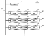
- FIG. 1 is a block diagram illustrating a configuration of a control system 100 according to the embodiment.
- the control system 100 includes a master control unit 10, a plurality of devices 20, and a signal line 30.
- the master control unit 10 generates control data for the plurality of devices 20.
- the control data is output from the signal line 30.
- the plurality of devices 20 are connected to the signal line 30.
- Device identification information is assigned in advance to each of the plurality of devices 20.
- the device identification information is information selected so as to be different from each other from a plurality of candidate information (for example, a number of multiple digits or a combination of a number and a character string) that can be identification information.
- the device identification information is a serial number, for example, and is given when the device 20 is shipped.
- a plurality of candidate information is divided into a plurality of groups in advance.
- Each of the plurality of groups is given group identification information in advance.
- the device identification information is a serial number
- the number of candidate information belonging to each group is N
- the group identification information of the group to which each device 20 belongs (hereinafter referred to as a belonging group) This is a quotient when 20 pieces of device identification information are divided by N.
- Each device 20 includes a control unit 22.
- the control unit 22 controls communication between the device 20 and the master control unit 10. The functions of the control unit 22 will be described later.
- the device 20 is a light emitting module.
- the device 20 will be described as a light emitting module.
- the device 20 may be a device other than the light emitting module.
- the device 20 includes a light emission control unit 24 and a light source 26 in addition to the control unit 22.
- the light source 26 is, for example, an organic EL or LED. However, the light source 26 may be another light source.
- the light source 26 is, for example, a panel light source, but may not be a panel shape.
- the light emission control unit 24 controls the light source 26. Specifically, the light emission control unit 24 controls the light source 26 according to control data transmitted from the master control unit 10 via the signal line 30.
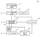
- FIG. 2 is a diagram illustrating a functional configuration of the master control unit 10.
- the master control unit 10 includes a group identification information output unit 120, an address storage unit 150, an address assignment unit 160, and an address output unit 170.
- the group identification information output unit 120 sequentially outputs the plurality of group identification information to the plurality of devices 20 via the signal line 30 with a time interval.
- Each of the plurality of devices 20 transmits the device identification information of the device 20 via the signal line 30 when group identification information corresponding to the group including the device identification information of the device 20 is transmitted, as will be described later.
- the address assigning unit 160 associates the device identification information transmitted from each of the plurality of devices 20 with different addresses.
- the address storage unit 150 stores a plurality of pieces of device identification information in association with addresses. This address is used when the master control unit 10 controls the light emission of the light source 26.
- the address output unit 170 outputs the address stored in the address storage unit 150 to the device 20 via the signal line 30 in association with the device identification information corresponding to the address.
- the master control unit 10 further includes a group identification information storage unit 110, a master-side timer 130, and a device identification information storage processing unit 140.
- the group identification information storage unit 110 stores group identification information.
- the group specifying information is information for recognizing the group identification information of each group, and is a function for calculating the group identification information, or the group identification information itself.
- the group identification information output unit 120 recognizes a plurality of group identification information based on the information stored in the group identification information storage unit 110.
- the master timer 130 counts the time after the group identification information output unit 120 outputs the group identification information.
- the group identification information output unit 120 outputs the next group identification information and initializes the count value of the master timer 130.
- the device identification information storage processing unit 140 causes the address storage unit 150 to store the device identification information transmitted from the device 20.
- FIG. 3 is a diagram illustrating a functional configuration of the control unit 22.
- the control unit 22 includes a device identification information storage unit 210, a specific information storage unit 220, a group determination unit 230, a device identification information output unit 250, and an address setting unit 260.
- the device identification information storage unit 210 stores device identification information of the device 20.
- the device identification information storage unit 210 stores an address transmitted from the master control unit 10 to the device 20.
- the specific information storage unit 220 stores information for identifying the group identification information of the group to which the device 20 belongs from the device identification information of the device 20 (hereinafter referred to as belonging group identification information). For example, when the device identification information is a serial number and the group identification information of the belonging group is a quotient obtained by dividing the device identification information by N, the belonging group identification information stores N.
- the group determination unit 230 calculates group identification information of the belonging group based on the device identification information of the device 20 and the belonging group specifying information. Then, the group determination unit 230 determines whether the group identification information output from the master control unit 10 corresponds to the belonging group.
- the device identification information output unit 250 receives the group identification information after the standby time has elapsed.
- the device identification information is output to the master control unit 10.
- the standby time is determined based on the order of the device identification information of the device 20 in the group to which it belongs.
- the standby time is, for example, a time obtained by multiplying a constant when the device identification information of the device 20 is divided by N.
- the control unit 22 further includes a device-side timer 240.
- the device-side timer 240 starts counting after initializing the count value.
- FIG. 4 is a diagram illustrating an example of a configuration of data used in communication between the master control unit 10 and the device 20.
- the data structure shown in this figure conforms to the DMX512-A standard.
- EIA-485 standard (RS-485 standard) is adopted as the electrical specification of the communication line. For this reason, communication between the master control unit 10 and the device 20 is asynchronous serial communication.
- the data format is composed of a 1-byte start code followed by a 512-byte data portion after a start signal called a break signal.
- a null command is used when performing various controls such as lighting control.
- a unique command is used, “0x91” is used as the start code.
- MIDs MID-H, MID-L
- Manufacture ID are used in the next two bytes of the start code. Then, a unique command and data are transmitted using the remaining 510 bytes.
- FIG. 4A shows a format of data transmitted from the master control unit 10 to the device 20.
- the command is transmitted. Necessary information is transmitted in bytes after the command.
- the commands include an address automatic setting mode start command, an address automatic setting mode end command, a device identification information response request command, an address setting command, and a count restart instruction command.
- the address automatic setting mode start command is a command for instructing the device 20 to start a mode for automatically setting an address.
- the automatic address setting mode end command is a command for instructing the device 20 to end the mode for automatically setting the address.
- the device identification information response request command is a command used together with group identification information, and is a command for requesting device identification information from the devices 20 belonging to the group indicated by the group identification information.
- the address setting command is a command used together with device identification information and an address corresponding to the device identification information, and is a command that requests the device 20 having the device identification information to set the address.
- FIG. 4B shows a format of data transmitted from the device 20 to the master control unit 10.
- a device identification information transmission command is transmitted.
- the device identification information transmission command is a command for identifying a response from the device 20, for example.
- the device identification information of the device 20 is transmitted.
- FIG. 4A A specific example of the data shown in FIG. 4A is shown in FIG. 4A is shown in FIG. 4A is shown in FIG.
- FIG. 4B A specific example of the data shown in FIG. 4B is shown in FIG.
- FIG. 7 is a flowchart showing an example of the operation of the control system 100 shown in FIG.
- the group identification information output unit 120 of the master control unit 10 outputs an address automatic setting mode start command to the signal line 30 (step S10).
- the group determination unit 230 of the control unit 22 of the device 20 receives the address automatic setting mode start command, the group identification information stored in the specific information storage unit 220 and the device stored in the device identification information storage unit 210 are stored.
- group identification information of the group to which the device 20 belongs is calculated (step S20).
- the group determination unit 230 also calculates a standby time until the device identification information is output.
- the group identification information output unit 120 sequentially outputs the group identification information together with the device identification information response request command to the signal line 30 (step S30).
- the master timer 130 counts after initializing the count value (step S35).
- the group determination unit 230 of the control unit 22 receives the group identification information output to the signal line 30, and determines whether or not it matches the group identification information of the belonging group calculated in step S20 (step S40). If they match (step S40: Yes), the group determination unit 230 starts the device-side timer 240 (step S50) and instructs the device identification information output unit 250 to output the device identification information to the signal line 30. Is output.
- the device identification information output unit 250 Upon receiving the command from the group determination unit 230, the device identification information output unit 250 checks whether or not the count value of the device-side timer 240 matches the standby time calculated by the group determination unit 230 (step S60). . If the count value of the device-side timer 240 matches the standby time (step S60: Yes), the device identification information stored in the device identification information storage unit 210 is output to the signal line 30 together with the device identification information transmission command. (Step S70).
- the device identification information storage processing unit 140 of the master control unit 10 receives the device identification information (step S72) and receives the received device identification information.
- the identification information is stored in the address storage unit 150 (step S80).
- the group identification information output unit 120 changes the group identification information to the next value (step S100). ).
- the group identification information output unit 120 sets the group identification information after changing the value as the number of groups (for example, the quotient when the number of candidate information is divided by N: the number obtained by adding 1 to the quotient when there is a remainder).
- the process returns to step S30.
- the group identification information output unit 120 causes the address assignment unit 160 to perform an address setting process. Specifically, the address assigning unit 160 assigns a different address (for example, a DMX address) to each piece of device identification information stored in the address storage unit 150 (step S120).
- a DMX address for example, a DMX address
- the address output unit 170 of the master control unit 10 sequentially outputs the device identification information stored in the address storage unit 150 to the signal line 30 as an address setting command in association with the address corresponding to the device identification information. (Step S130).
- the address setting unit 260 of the device 20 also includes the same in the address setting command.
- the address corresponding to the device identification information is stored in the device identification information storage unit 210 (step S132).
- Step S140 When the address output unit 170 of the master control unit 10 finishes outputting all the device identification information stored in the address storage unit 150 together with the address to the signal line 30, it outputs an address automatic setting mode end command to the signal line 30. (Step S140). When an address automatic setting mode end command flows through the signal line 30, the control unit 22 ends the address setting process.
- the address assigning unit 160 may assign an address to the device identification information at the timing when the device identification information is stored in the address storage unit 150 and store the address in the address storage unit 150.
- a plurality of candidate information that can be device identification information is divided into a plurality of groups in advance. Group identification information is assigned to each of the plurality of groups.
- the master control unit 10 sequentially outputs group identification information to the signal line 30.
- the control unit 22 of the device 20 outputs the device identification information stored in the control unit 22 to the signal line 30.
- the control unit 22 outputs the device identification information after the standby time has elapsed after receiving the group identification information.
- the standby time is determined based on the order of the device identification information of the device 20 in the group to which it belongs. Accordingly, a plurality of device identification information is not simultaneously output to the signal line 30. Therefore, the master control unit 10 can efficiently acquire the device identification information of the device 20 connected to the signal line 30.
- the master control unit 10 outputs group identification information to the signal line 30. For this reason, the number of times that the master control unit 10 outputs the identification information to the signal line 30 is smaller than the number of times that the device identification information is output. Therefore, the time required for obtaining the device identification information of the device 20 connected to the signal line 30 is short. For this reason, the time required for setting an address in the control unit 22 is short.
- the group identification information can be a quotient obtained by dividing the device identification information of the device 20 by N, and the standby time can be set to a value obtained by multiplying the remainder by a constant. In this case, group identification information and standby time can be easily calculated.
- Example 1 When there are a plurality of devices 20 having the same group identification information, the count value of the timer 240 of the other device 20 reaches the standby time while one device 20 is transmitting the device identification information, and the device identification information is There is a risk of sending. In this case, the master control unit 10 may not be able to receive the device identification information of the device 20 transmitted later. Therefore, the control system 100 according to the present embodiment adds the time required for this process to the timeout time of the master-side timer 130 of the master control unit 10 and the standby time of the control unit 22 of the device 20.
- FIG. 8 is a diagram illustrating a functional configuration of the master control unit 10 according to the present embodiment.
- the master control unit 10 according to the present embodiment is the same as the master control unit 10 according to the embodiment except that the device identification information storage processing unit 140 notifies the group identification information output unit 120 that the device identification information has been received. It is the same composition as.
- control unit 22 of the device 20 is the same as that of the embodiment in the block diagram.
- FIG. 9 is a flowchart showing the operation of the control system 100 in the present embodiment. This figure is the same as the flowchart shown in FIG. 7 except for the following points.
- the group determination unit 230 of the control unit 22 outputs device identification information from the other control unit 22 to the signal line 30 (step S51: Yes).
- the device-side timer 240 is temporarily stopped (step S52).
- the master control unit 10 outputs a signal (count restart instruction information) indicating that the process of storing the device identification information in the address storage unit 150 is completed to the signal line 30, and the count restart instruction information is transmitted to the signal line 30.
- Step S53: Yes the operation of the device-side timer 240 is restarted (step S56).
- the group identification information output unit 120 of the master control unit 10 stores the received device identification information in the address storage unit 150 ( In step S80), the count restart instruction information is output to the signal line 30, and a signal indicating that the device identification information has been received is output to the group identification information output unit 120.
- the group identification information output unit 120 adds a predetermined time (time for receiving the device identification information) to the timeout time (step S84).
- the same effect as in the embodiment can be obtained.
- the time required for the master control unit 10 to receive the device identification signal is added to the timeout time of the master timer 130 of the master control unit 10.
- the device-side timer 240 is temporarily stopped so that the standby time of the control unit 22 of the device 20 is not affected. Therefore, the master control unit 10 can capture the device identification information of the device 20 more reliably.
- Example 2 If the same number of device identification signals as the number of devices 20 connected to the signal line 30 are stored in the address storage unit 150, subsequent device identification signal acquisition processing is wasted. In this embodiment, this waste is eliminated.
- FIG. 10 is a diagram illustrating a functional configuration of the master control unit 10 according to the present embodiment.
- the master control unit 10 according to the present embodiment has the same configuration as the master control unit 10 illustrated in FIG. 8 except that a device number storage unit 185 is provided.
- the device number storage unit 185 stores the number of the plurality of devices 20 connected to the signal line 30.
- the device identification information storage processing unit 140 addresses the device identification information when the number of device identification information stored in the address output unit 170 reaches the number of devices stored in the device number storage unit 185.
- the process of storing in the storage unit 150 ends.
- control unit 22 of the device 20 is the same as that of the embodiment in the block diagram.
- FIG. 11 is a flowchart showing the operation of the control system 100 in the present embodiment. This figure is the same as the flowchart shown in FIG. 9 except for the following points.
- the device identification information storage processing unit 140 of the master control unit 10 stores a count value.
- the initial value of this count value is zero.
- the device identification information storage processing unit 140 stores the device identification information in the address storage unit 150
- the device identification information storage processing unit 140 increases the count value by one.
- the processing end information output unit 180 sends an address setting command (processing end information) via the signal line 30. Are output to a plurality of devices 20 (step S130).
- the same effect as in the embodiment can be obtained.
- the device identification information storage processing unit 140 ends the device identification information acquisition process. .
- the time required for obtaining the device identification information of the device 20 connected to the signal line 30 is further shortened. Therefore, the time required for setting an address in the control unit 22 is further shortened.
- the count restart of the control timer of the control unit 22 of the device 20 is performed by a count restart instruction command from the master control unit 10.
- the time for transmitting the count restart instruction command is wasted. In this embodiment, this waste is eliminated.
- control unit 22 of the device 20 is the same as that of the embodiment in the block diagram.
- FIG. 12 is a flowchart showing the operation of the control system 100 in this embodiment. This figure is the same as the flowchart shown in FIG. 9 except for the following points.
- step S84 In the master control unit 10, after performing the processing shown in step S80, when the device identification information storage processing unit 140 of the master control unit 10 stores the device identification information in the address storage unit 150, the count restart instruction information The output (step S82 in FIG. 11) is not performed, and the process proceeds to the timeout time correction (S84).
- control part 22 receives the response by the other apparatus 20 (step S51: Yes), pauses the count of the apparatus side timer 240 (step S52), and then by the other apparatus 20 When it is detected that the transmission of the device identification information has been completed (step S54: Yes), the counting of the device side timer 240 is restarted.
- the same effect as in the embodiment can be obtained.
- the count of the device-side timer is restarted by detecting the completion of the transmission of the device identification information of the other device 20, it is shorter than the time necessary for transmitting the count restart instruction information as compared with the second embodiment. Become. Therefore, the time required for setting an address in the control unit 22 is further shortened.
Landscapes
- Engineering & Computer Science (AREA)
- Computer Networks & Wireless Communication (AREA)
- Signal Processing (AREA)
- General Engineering & Computer Science (AREA)
- Physics & Mathematics (AREA)
- General Physics & Mathematics (AREA)
- Automation & Control Theory (AREA)
- Small-Scale Networks (AREA)
Abstract
Description
前記複数の機器に対する制御データを生成するマスタ制御部と、
を備え、
前記複数の機器それぞれには、識別情報となりうる複数の候補情報から互いに異なるように選択された機器識別情報が予め付与されており、
前記複数の候補情報は、予め複数のグループに分けられており、
前記複数のグループのそれぞれには、予めグループ識別情報が付与されており、
前記マスタ制御部は、前記複数のグループ識別情報を、時間を空けて順次前記複数の機器に出力するグループ識別情報出力部を備え、
前記機器は、
当該機器の前記機器識別情報を記憶する機器識別情報記憶部と、
当該機器の前記機器識別情報を含む前記グループである所属グループの前記グループ識別情報を、当該機器の前記機器識別情報から特定するための所属グループ特定情報を記憶する特定情報記憶部と、
当該機器の前記機器識別情報及び前記所属グループ特定情報に基づいて、前記マスタ制御部から出力された前記グループ識別情報が前記所属グループに対応しているか否かを判断するグループ判断部と、
前記マスタ制御部から出力された前記グループ識別情報が前記所属グループに対応している場合に、前記所属グループ内における当該機器の前記機器識別情報の順序に基づいて定められる待機時間経過後に、前記機器識別情報を前記マスタ制御部に出力する機器識別情報出力部と、
を備え、
前記マスタ制御部は、さらに、
前記複数の機器のそれぞれから送信されてきた前記機器識別情報に、互いに異なるアドレスを付与するアドレス付与部と、
前記複数の機器識別情報を前記アドレスに対応付けて記憶するアドレス記憶部と、
前記機器識別情報及び前記アドレスを互いに対応付けて前記機器に出力するアドレス出力部と、
を備え、
前記機器は、さらに、当該機器の機器識別情報記憶部が記憶している前記機器識別情報に対応付けて前記アドレスが送信されてきた場合に、当該アドレスを記憶する処理を行うアドレス設定部を備える制御システムである。
図1は、実施形態に係る制御システム100の構成を示すブロック図である。実施形態に係る制御システム100は、マスタ制御部10、複数の機器20、及び信号線30を備えている。マスタ制御部10は、複数の機器20に対する制御データを生成する。信号線30は、この制御データが出力される。複数の機器20は、信号線30に接続されている。
同一のグループ識別情報を所有する機器20が複数存在する場合、一方の機器20が機器識別情報を送信中に他方の機器20のタイマー240のカウント値が待機時間に達してしまい、機器識別情報を送信する恐れがある。この場合、マスタ制御部10は、後から送信された機器20の機器識別情報を受信ができない恐れがある。そこで本実施例に係る制御システム100は、マスタ制御部10のマスタ側タイマー130のタイムアウト時間及び機器20の制御部22の待機時間に、この処理に必要な時間を加算する。
信号線30に接続している機器20の数と同じ数の機器識別信号がアドレス記憶部150に記憶されれば、その後の機器識別信号の取得処理は無駄になる。本実施例は、この無駄を省くようにしたものである。
実施例1,2において、機器20の制御部22の制御側タイマーのカウント再開はマスタ制御部10からのカウント再開指示コマンドにより行われている。しかし、カウント再開指示コマンドを送信する時間は無駄となる。本実施例は、この無駄を省くようにしたものである。
Claims (8)
- 複数の機器と、
前記複数の機器に対する制御データを生成するマスタ制御部と、
を備え、
前記複数の機器それぞれには、識別情報となりうる複数の候補情報から互いに異なるように選択された機器識別情報が予め付与されており、
前記複数の候補情報は、予め複数のグループに分けられており、
前記複数のグループのそれぞれには、予めグループ識別情報が付与されており、
前記マスタ制御部は、前記複数のグループ識別情報を、時間を空けて順次前記複数の機器に出力するグループ識別情報出力部を備え、
前記機器は、
当該機器の前記機器識別情報を記憶する機器識別情報記憶部と、
当該機器の前記機器識別情報を含む前記グループである所属グループの前記グループ識別情報を、当該機器の前記機器識別情報から特定するための所属グループ特定情報を記憶する特定情報記憶部と、
当該機器の前記機器識別情報及び前記所属グループ特定情報に基づいて、前記マスタ制御部から出力された前記グループ識別情報が前記所属グループに対応しているか否かを判断するグループ判断部と、
前記マスタ制御部から出力された前記グループ識別情報が前記所属グループに対応している場合に、前記所属グループ内における当該機器の前記機器識別情報の順序に基づいて定められる待機時間経過後に、前記機器識別情報を前記マスタ制御部に出力する機器識別情報出力部と、
を備え、
前記マスタ制御部は、さらに、
前記複数の機器のそれぞれから送信されてきた前記機器識別情報に、互いに異なるアドレスを付与するアドレス付与部と、
前記複数の機器識別情報を前記アドレスに対応付けて記憶するアドレス記憶部と、
前記機器識別情報及び前記アドレスを互いに対応付けて前記機器に出力するアドレス出力部と、
を備え、
前記機器は、さらに、当該機器の前記機器識別情報記憶部が記憶している前記機器識別情報に対応付けて前記アドレスが送信されてきた場合に、当該アドレスを記憶する処理を行うアドレス設定部を備える制御システム。 - 請求項1に記載の制御システムにおいて、
前記機器識別情報は、前記機器の出荷時に付与されるシリアル番号である制御システム。 - 請求項2に記載の制御システムにおいて、
一つの前記グループに属する前記候補情報の数をNとした場合、前記機器の前記所属グループの前記グループ識別情報は、当該機器の前記機器識別情報をNで除したときの商であり、
前記待機時間は、当該機器の前記機器識別情報をNで除したときの余りに定数を乗じた時間である制御システム。 - 請求項1~3のいずれか一項に記載の制御システムにおいて、
前記複数の機器は、それぞれ機器側タイマーを備えており、
前記機器の前記機器識別情報出力部は、前記機器側タイマーのカウント値に基づいて、前記待機時間を経過したか否かを判断し、
前記機器側タイマーは、
前記所属グループの前記グループ識別情報を受信したときに初期値からカウントを開始し、
いずれかの前記機器が前記機器識別情報を前記マスタ制御部に出力したときに、カウントを一時中断する制御システム。 - 請求項4に記載の制御システムにおいて、
前記機器側タイマーは、カウントを一時中断した後、前記いずれかの機器が前記マスタ制御部への前記機器識別情報の出力を完了した時に、カウントを再開する制御システム。 - 請求項4に記載の制御システムにおいて、
前記マスタ制御部の前記アドレス記憶部は、前記機器識別情報を記憶すると、カウント再開指示情報を前記複数の機器に出力し、
カウントを一時中断している前記機器側タイマーは、前記カウント再開指示情報を受信すると、カウントを再開する制御システム。 - 請求項1~6のいずれか一項に記載の制御システムにおいて、
前記マスタ制御部は、
前記複数の機器の数を記憶する機器数記憶部と、
前記アドレス記憶部が記憶している前記機器識別情報の数が、前記機器数記憶部が記憶している前記機器の数に達したときに、前記アドレス記憶部に前記機器識別情報を記憶させる処理を終了する機器識別情報記憶処理部を備える制御システム。 - 請求項1に記載の制御システムにおいて、前記機器は発光モジュールである制御システム。
Priority Applications (3)
| Application Number | Priority Date | Filing Date | Title |
|---|---|---|---|
| US14/772,168 US20160033948A1 (en) | 2013-03-07 | 2013-03-07 | Control system |
| PCT/JP2013/056347 WO2014136244A1 (ja) | 2013-03-07 | 2013-03-07 | 制御システム |
| JP2015504073A JP6026640B2 (ja) | 2013-03-07 | 2013-03-07 | 制御システム |
Applications Claiming Priority (1)
| Application Number | Priority Date | Filing Date | Title |
|---|---|---|---|
| PCT/JP2013/056347 WO2014136244A1 (ja) | 2013-03-07 | 2013-03-07 | 制御システム |
Publications (1)
| Publication Number | Publication Date |
|---|---|
| WO2014136244A1 true WO2014136244A1 (ja) | 2014-09-12 |
Family
ID=51490802
Family Applications (1)
| Application Number | Title | Priority Date | Filing Date |
|---|---|---|---|
| PCT/JP2013/056347 Ceased WO2014136244A1 (ja) | 2013-03-07 | 2013-03-07 | 制御システム |
Country Status (3)
| Country | Link |
|---|---|
| US (1) | US20160033948A1 (ja) |
| JP (1) | JP6026640B2 (ja) |
| WO (1) | WO2014136244A1 (ja) |
Cited By (1)
| Publication number | Priority date | Publication date | Assignee | Title |
|---|---|---|---|---|
| US10925315B2 (en) | 2015-03-26 | 2021-02-23 | Philip Morris Products S.A. | Heater management |
Citations (3)
| Publication number | Priority date | Publication date | Assignee | Title |
|---|---|---|---|---|
| JPH10191466A (ja) * | 1996-12-24 | 1998-07-21 | Toshiba Lighting & Technol Corp | 遠隔制御装置および調光システム |
| WO2004062197A1 (ja) * | 2002-12-27 | 2004-07-22 | Sharp Kabushiki Kaisha | 親機および子機の通信制御方法、通信ネットワークシステム、親機、子機、親機用通信制御プログラム、子機用通信制御プログラム、並びに該プログラムを記録した記録媒体 |
| JP2008109514A (ja) * | 2006-10-26 | 2008-05-08 | Matsushita Electric Works Ltd | 負荷制御システム |
Family Cites Families (8)
| Publication number | Priority date | Publication date | Assignee | Title |
|---|---|---|---|---|
| GB2338809B (en) * | 1998-06-25 | 2000-08-30 | Matsushita Electric Works Ltd | Remote supervisory control system |
| JP3466501B2 (ja) * | 1999-03-26 | 2003-11-10 | フーリエ有限会社 | セレクタ |
| US20040176877A1 (en) * | 2003-03-05 | 2004-09-09 | Scott Hesse | Building automation system and method |
| JP2006190210A (ja) * | 2005-01-07 | 2006-07-20 | Fuji Xerox Co Ltd | 非接触ic |
| US20090165074A1 (en) * | 2007-12-21 | 2009-06-25 | General Instrument Corporation | Multi-Address Message Addressing |
| ATE523010T1 (de) * | 2009-04-14 | 2011-09-15 | Actaris Sas | Bidirektionelle drahtlose signalübertragung von seriendaten zwischen einer elektronischen vorrichtung und einem stromzähler |
| JP5337124B2 (ja) * | 2010-09-22 | 2013-11-06 | アズビル株式会社 | 無線通信システム |
| JP6121195B2 (ja) * | 2013-02-27 | 2017-04-26 | 国立大学法人 東京大学 | 無線通信システム、無線機、及びプログラム |
-
2013
- 2013-03-07 US US14/772,168 patent/US20160033948A1/en not_active Abandoned
- 2013-03-07 JP JP2015504073A patent/JP6026640B2/ja not_active Expired - Fee Related
- 2013-03-07 WO PCT/JP2013/056347 patent/WO2014136244A1/ja not_active Ceased
Patent Citations (3)
| Publication number | Priority date | Publication date | Assignee | Title |
|---|---|---|---|---|
| JPH10191466A (ja) * | 1996-12-24 | 1998-07-21 | Toshiba Lighting & Technol Corp | 遠隔制御装置および調光システム |
| WO2004062197A1 (ja) * | 2002-12-27 | 2004-07-22 | Sharp Kabushiki Kaisha | 親機および子機の通信制御方法、通信ネットワークシステム、親機、子機、親機用通信制御プログラム、子機用通信制御プログラム、並びに該プログラムを記録した記録媒体 |
| JP2008109514A (ja) * | 2006-10-26 | 2008-05-08 | Matsushita Electric Works Ltd | 負荷制御システム |
Cited By (1)
| Publication number | Priority date | Publication date | Assignee | Title |
|---|---|---|---|---|
| US10925315B2 (en) | 2015-03-26 | 2021-02-23 | Philip Morris Products S.A. | Heater management |
Also Published As
| Publication number | Publication date |
|---|---|
| JP6026640B2 (ja) | 2016-11-16 |
| US20160033948A1 (en) | 2016-02-04 |
| JPWO2014136244A1 (ja) | 2017-02-09 |
Similar Documents
| Publication | Publication Date | Title |
|---|---|---|
| JP6223576B2 (ja) | アドレス指定可能な照明のためのタブレットに基づくコミッショニングツール | |
| US9560727B2 (en) | Apparatus and method for creating functional wireless lighting groups | |
| TWI685786B (zh) | 用於現場可程式邏輯閘陣列的韌體更新方法 | |
| CN106164887B (zh) | 总线地址分配 | |
| US11169944B2 (en) | Communication device, communication method, program, and communication system | |
| JP6659721B2 (ja) | ネットワーク接続照明システムの構成法 | |
| CN105101530A (zh) | 以同步于ac电源频率为基础的调控系统与调控方法 | |
| KR20150032765A (ko) | 조광제어시스템 | |
| JP6026640B2 (ja) | 制御システム | |
| CN110572911B (zh) | 一种级联设备的地址编码方法、地址编码系统及光照系统 | |
| KR20190033041A (ko) | 리니어 모터 시스템 및 그 구동 방법 | |
| EP2387293A2 (en) | Illumination system | |
| CN111008161B (zh) | 一种控制方法 | |
| CN108881514A (zh) | 总线系统的地址分配方法、通讯设备和总线系统 | |
| TW201608929A (zh) | 具有可燒錄功能之發光二極體燈及燈串及系統 | |
| JP2011113761A (ja) | 照明制御システム | |
| AU2014403782B2 (en) | DALI device addressing method and software | |
| JP7774227B2 (ja) | 電気機器、電気機器システム、及び制御方法 | |
| CN113495864A (zh) | 受控装置、主控装置及数据传输方法 | |
| JP7808772B2 (ja) | 電気機器、電気機器システム、及び制御方法 | |
| TW201210407A (en) | Driving apparatus of lighting device, driving system of lighting device and driving method thereof | |
| US12193128B2 (en) | Commissioning of lighting systems using Bluetooth direction finding | |
| US10620601B2 (en) | Control device, control system, and search method | |
| JP2019160425A (ja) | 制御システム | |
| CN106804088A (zh) | 基于绕线机的灯光控制方法及系统 |
Legal Events
| Date | Code | Title | Description |
|---|---|---|---|
| 121 | Ep: the epo has been informed by wipo that ep was designated in this application |
Ref document number: 13877030 Country of ref document: EP Kind code of ref document: A1 |
|
| ENP | Entry into the national phase |
Ref document number: 2015504073 Country of ref document: JP Kind code of ref document: A |
|
| WWE | Wipo information: entry into national phase |
Ref document number: 14772168 Country of ref document: US |
|
| NENP | Non-entry into the national phase |
Ref country code: DE |
|
| 122 | Ep: pct application non-entry in european phase |
Ref document number: 13877030 Country of ref document: EP Kind code of ref document: A1 |