WO2014136186A1 - 歯車ポンプ又はモータ - Google Patents
歯車ポンプ又はモータ Download PDFInfo
- Publication number
- WO2014136186A1 WO2014136186A1 PCT/JP2013/055860 JP2013055860W WO2014136186A1 WO 2014136186 A1 WO2014136186 A1 WO 2014136186A1 JP 2013055860 W JP2013055860 W JP 2013055860W WO 2014136186 A1 WO2014136186 A1 WO 2014136186A1
- Authority
- WO
- WIPO (PCT)
- Prior art keywords
- hydraulic
- driven
- gear
- drive shaft
- shaft
- Prior art date
- Legal status (The legal status is an assumption and is not a legal conclusion. Google has not performed a legal analysis and makes no representation as to the accuracy of the status listed.)
- Ceased
Links
Images

Classifications
-
- F—MECHANICAL ENGINEERING; LIGHTING; HEATING; WEAPONS; BLASTING
- F04—POSITIVE - DISPLACEMENT MACHINES FOR LIQUIDS; PUMPS FOR LIQUIDS OR ELASTIC FLUIDS
- F04C—ROTARY-PISTON, OR OSCILLATING-PISTON, POSITIVE-DISPLACEMENT MACHINES FOR LIQUIDS; ROTARY-PISTON, OR OSCILLATING-PISTON, POSITIVE-DISPLACEMENT PUMPS
- F04C2/00—Rotary-piston machines or pumps
- F04C2/08—Rotary-piston machines or pumps of intermeshing-engagement type, i.e. with engagement of co-operating members similar to that of toothed gearing
- F04C2/12—Rotary-piston machines or pumps of intermeshing-engagement type, i.e. with engagement of co-operating members similar to that of toothed gearing of other than internal-axis type
- F04C2/14—Rotary-piston machines or pumps of intermeshing-engagement type, i.e. with engagement of co-operating members similar to that of toothed gearing of other than internal-axis type with toothed rotary pistons
- F04C2/16—Rotary-piston machines or pumps of intermeshing-engagement type, i.e. with engagement of co-operating members similar to that of toothed gearing of other than internal-axis type with toothed rotary pistons with helical teeth, e.g. chevron-shaped, screw type
-
- F—MECHANICAL ENGINEERING; LIGHTING; HEATING; WEAPONS; BLASTING
- F04—POSITIVE - DISPLACEMENT MACHINES FOR LIQUIDS; PUMPS FOR LIQUIDS OR ELASTIC FLUIDS
- F04C—ROTARY-PISTON, OR OSCILLATING-PISTON, POSITIVE-DISPLACEMENT MACHINES FOR LIQUIDS; ROTARY-PISTON, OR OSCILLATING-PISTON, POSITIVE-DISPLACEMENT PUMPS
- F04C15/00—Component parts, details or accessories of machines, pumps or pumping installations, not provided for in groups F04C2/00 - F04C14/00
- F04C15/0003—Sealing arrangements in rotary-piston machines or pumps
- F04C15/0034—Sealing arrangements in rotary-piston machines or pumps for other than the working fluid, i.e. the sealing arrangements are not between working chambers of the machine
-
- F—MECHANICAL ENGINEERING; LIGHTING; HEATING; WEAPONS; BLASTING
- F04—POSITIVE - DISPLACEMENT MACHINES FOR LIQUIDS; PUMPS FOR LIQUIDS OR ELASTIC FLUIDS
- F04C—ROTARY-PISTON, OR OSCILLATING-PISTON, POSITIVE-DISPLACEMENT MACHINES FOR LIQUIDS; ROTARY-PISTON, OR OSCILLATING-PISTON, POSITIVE-DISPLACEMENT PUMPS
- F04C15/00—Component parts, details or accessories of machines, pumps or pumping installations, not provided for in groups F04C2/00 - F04C14/00
- F04C15/0042—Systems for the equilibration of forces acting on the machines or pump
Definitions
- the present invention relates to a gear pump or a motor provided with an external gear pair composed of a drive gear and a driven gear each utilizing helical gears that mesh with each other, and a casing having a gear storage chamber for storing the external gear pair therein. .
- a gear pump or a motor including an external gear pair that includes a drive gear and a driven gear that mesh with each other and a casing that internally includes a gear storage chamber that stores the external gear pair has been widely used.
- the spur gear in which teeth parallel to the axis are formed around the drive gear and driven gear of such a gear pump or motor is the mainstream.
- a spur gear is used for the drive gear and the driven gear, there are the following problems. Specifically, when the teeth of the drive gear and the teeth of the driven gear mesh with each other, they mesh simultaneously over the entire tooth width. Further, when the meshing between the teeth of the drive gear and the teeth of the driven gear is terminated, the meshing is simultaneously terminated over the entire tooth width. This can cause noise and vibration.
- a contrivance has been proposed in which helical gears are used as the drive gear and the driven gear (see, for example, Patent Document 1).
- Such a gear pump or motor has the following configuration, for example. That is, as shown in FIG. 4, an external gear pair X1 composed of a driving side helical gear X6 and a driven side helical gear X7, and a gear storage chamber X2a for storing the external gear pair X1 are internally provided.
- a casing X2 having a bearing for housing a drive shaft X8 for supporting the helical gear X6 on the driving side and a driven shaft X9 for supporting the driven helical gear X7 on the driving side is housed in the casing X2.
- a rear-side bearing case X3a and a front-side bearing case X3b that serve as a pair of side plates that are in contact with both side surfaces X6a, X6b, X7a, and X7b of the helical gears X6 and X7, respectively.
- the hydraulic shafts X41a and X41b have hydraulic chambers X41a and X41b, and the drive shaft X8 and the driven shaft X9 are anti-thrusted by the hydraulic pressure introduced into the hydraulic chambers X41a and X41b.
- the casing X2 includes a cylindrical body X23 having the gear housing chamber X2a, a front cover X22 attached to the front side of the body X23, and a rear cover X24 attached to the rear side of the body X23.
- a rear bearing case X3b that pivotally supports the front end side of the driven shaft X9.
- the bearing case X3a on the rear side receives a large surface pressure due to the thrust load.
- the balance pistons X43a and X43b of the hydraulic mechanism X4 are arranged on the rear end side of the drive shaft X8 and the driven shaft X9. Are brought into contact with each other and balanced by liquid pressure. As a result, the balance pistons X43a and X43b can apply a pressing force proportional to the fluid pressure against the thrust load.
- the hydraulic mechanism X4 has a configuration in which the balance pistons X43a and X43b of the hydraulic mechanism X4 are in contact with the rear ends of the drive shaft X8 and the driven shaft X9, the following problems may occur. . That is, in such a configuration, friction occurs between the balance pistons X43a and X43b as the drive shaft X8 and the driven shaft X9 rotate, and the balance pistons X43a and X43b transmit torque from the drive shaft X8 and the driven shaft X9. May rotate in response.
- the present invention focuses on the above points, and in a gear pump or motor having a pair of external gears composed of a helical gear on the driving side and a helical gear on the driven side that mesh with each other, the piston is used as the driving shaft and the driven shaft.
- the intended purpose is to eliminate the problem that mechanical loss occurs when the drive shaft and the driven shaft are pressed in the anti-thrust direction in the contacted state.
- the gear pump or motor according to the present invention has the following configuration. That is, the gear pump or motor according to the present invention has an external gear pair composed of a driving side helical gear and a driven side helical gear meshing with each other, and a gear storage chamber for storing the external gear pair, and the drive.
- a casing having a drive shaft for supporting the helical gear on the side and a bearing for housing the driven shaft for supporting the driven helical gear on the driven side, and a hydraulic chamber are introduced into the hydraulic chamber.
- a gear pump comprising: a hydraulic mechanism that presses the drive shaft and the driven shaft in the anti-thrust direction by hydraulic pressure; and a high-pressure hydraulic fluid introduction passage that guides hydraulic fluid from the high-pressure side to the hydraulic pressure chamber of the hydraulic mechanism.
- a motor wherein the hydraulic pressure mechanism is opposed to the drive shaft or the driven shaft, and the drive side is located on the opposite side of the helical gear or the driven side is located on the opposite side of the helical gear.
- the drive shaft or driven shaft in the anti-thrust direction
- An orifice for introducing the liquid and a seal land formed on the outer peripheral portion of the surface facing the drive shaft or the driven shaft and projecting toward the drive shaft or the driven shaft are provided.
- the drive shaft and the driven shaft are pressed in the anti-thrust direction only by the hydraulic fluid pressure introduced into the hydraulic pressure chamber, so that the piston is connected to the drive shaft or the driven shaft. It is possible to prevent the occurrence of problems due to contact with the.
- the seal land is rotated along with the rotation of the drive shaft or the driven shaft. Since a fluid film having a gentle pressure gradient is generated in the space between the drive shaft and the driven shaft and the fluid pressure introduced into the central portion of the gap is maintained, this fluid pressure mechanism is used as a thrust bearing. Can be used as
- the driving shaft in a state where the piston is in contact with the driving shaft and the driven shaft. And the malfunction which mechanical loss generate
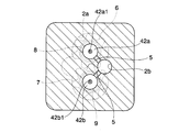
- FIG. 2 is a ZZ cross-sectional view in FIG. 1.
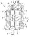
- the gear pump P ⁇ b> 1 accommodates an external gear pair 1 including a driving-side helical gear 6 and a driven-side helical gear 7 that mesh with each other, and the external gear pair 1.
- a casing 2 having a gear housing chamber 2a therein and a bearing for housing the drive shaft 8 that supports the helical gear 6 on the driving side and the driven shaft 9 that supports the helical gear 7 on the driven side.
- a rear plate 3a and a front plate 3b which are housed in the casing 2 and make a pair respectively contacting the both side surfaces 6a, 6b, 7a, 7b of the helical gears 6, 7;
- a hydraulic mechanism 4 having pressure chambers 41a and 41b and pressing the drive shaft 8 and the driven shaft 9 in the anti-thrust direction by the hydraulic pressure introduced into the hydraulic chambers 41a and 41b;
- the hydraulic fluid is guided to the pressure chambers 41a and 41b from the high pressure side. Comprising a pressure hydraulic fluid introducing passage 5.
- the driving-side helical gear 6 and the driven-side helical gear 7 constituting the external gear pair 1 are helical gears that are well known as those used in this type of gear pump.
- the teeth on the driving side of the helical gear 6 and the teeth on the driven side of the helical gear 7 are operated as a gear pump in a state where they are engaged with each other.
- the helical gear 6 receives a thrust load going backward
- the driven gear 7 receives a thrust load going forward.
- the helical gear 6 on the driving side and the helical gear 7 on the driven side receive thrust loads directed rearward by the hydraulic pressure while operating as a gear pump.
- the driving side is different in the helical gear 6 and the driven side is different in the helical gear 7.
- the thrust load is applied toward the rear.
- the drive side is provided with the helical gear 6 and the drive shaft 8 integrally.
- the drive shaft 8 extends from the center of the helical gear 6 on the drive side in the rotational axis direction.
- One end of the drive shaft 8 extends to the outside of the casing 2.
- the driven side is provided integrally with the helical gear 7 and the driven shaft 9.
- the driven shaft 9 extends from the center of the driven helical gear 7 in the direction of the rotational axis.
- the casing 2 includes a body 21 having a gear storage chamber 2a that opens forward, a front cover 22 attached to the front side of the body 21, and a rear cover 23 attached to the rear side of the body 21. .
- the body 21 has a substantially eyeglass-shaped gear housing chamber 2a for housing the external gear pair 1, that is, the driving-side helical gear 6 and the driven-side helical gear 7 in an engaged state, and the gear housing chamber 2a.
- the front cover 22 is detachably attached to the body 21 with bolts or the like, and closes the opening surface on the front side of the gear housing chamber 2a.
- the front cover 22 includes a bearing 26 that pivotally supports the front end sides of the drive shaft 8 and the driven shaft 9.
- Each bearing 26 is provided with a bearing hole 26x in which the front end sides of the drive shaft 8 and the driven shaft 9 can be respectively fitted, and an inner periphery of the bearing hole 26x so that the drive shaft 8 and the driven shaft 9 can slide.
- a supporting bush 26y is provided. The front end of the drive shaft 8 passes through the bearing hole 26x and protrudes to the outside of the casing 2.
- the rear cover 23 is also detachably attached to the body 21 with a bolt or the like, and closes the opening surface on the rear side of the gear housing chamber 2a.
- the rear cover 23 includes a bearing 25 that pivotally supports the rear end sides of the drive shaft 8 and the driven shaft 9.
- Each bearing 25 is provided with a bearing hole 25x into which the rear end sides of the drive shaft 8 and the driven shaft 9 can be respectively fitted, and is provided on the inner periphery of the bearing hole 25x so that the drive shaft 8 and the driven shaft 9 can slide.
- a bush 25y that supports the shaft is provided.
- the driving side is provided with the rear side plate 3 a attached to the rear side surface 6 a of the helical gear 6 and the driven side helical gear 7. Further, the driving side is provided with a front side plate 3b attached to the front side surface 6b of the helical gear 6 and the driven side helical surface 7b.
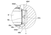
- the hydraulic mechanism 4 is formed in a rear cover 23 corresponding to the drive shaft 8 and the driven shaft 9, respectively, more specifically, a pair formed behind the bearing hole 25x. And hydraulic pressure chambers 41a and 41b, and pairs of shoes 42a and 42b slidably fitted in the hydraulic pressure chambers 41a and 41b, respectively.
- the shoes 42a and 42b are orifices for introducing hydraulic fluid into the gaps Sa and Sb formed between the shoes 42a and 42b and the drive shaft 8 or the driven shaft 9 from the hydraulic chambers 41a and 41b.
- 42 a 1, 42 b 1, and seal lands 42 a 2, 42 b 2 formed on the outer peripheral portion of the surface toward the drive shaft 8 or the driven shaft 9 and projecting toward the drive shaft 8 or the driven shaft 9.
- the high-pressure hydraulic fluid introduction path 5 is for guiding the hydraulic fluid from the high-pressure side to the hydraulic chambers 41a and 41b of the hydraulic mechanism 4, and is formed in the rear cover 23 as shown in FIG.
- the hydraulic fluid is guided from the hydraulic fluid discharge port 2b side to the hydraulic chambers 41a and 41b, and the shoes 42a and 42b and the drive shaft 8 or the driven shaft are further connected through the orifices 42a1 and 42b1 formed in the shoes 42a and 42b.
- the working fluid is also introduced into the gaps Sa and Sb formed between the shaft 9.
- the drive shaft 8 and the driven shaft 9 are pressed in the anti-thrust direction by a force derived from the hydraulic pressure of the hydraulic fluid.
- the outer peripheral portions of the gaps Sa and Sb that is, the portions where the seal lands 42a2 and 42b2 face the drive shaft 8 or the driven shaft 9 are narrower than the other portions. Therefore, when the drive shaft 8 and the driven shaft 9 are rotating, a fluid film having a gentle pressure gradient is formed in this portion, and the fluid pressure in the other portions of the gaps Sa and Sb is substantially maintained.
- the hydraulic mechanism 4 functions as a thrust bearing.
- the gear pump P1 introduces high-pressure hydraulic fluid from the hydraulic fluid discharge port 2b, thereby taking out rotational torque from the drive shaft 8 and driving an external load, and at the same time, operating the hydraulic fluid at low pressure in the operation. It goes without saying that it can also function as a gear motor that performs the motor action of discharging from the liquid suction port.
- the driving shaft 8 and the driven shaft 9 are anti-thrusted only by the hydraulic pressure introduced into the hydraulic pressure chambers 41a and 41b. Since the pressure is pressed in the direction, it is possible to prevent the occurrence of problems caused by bringing the piston into contact with the drive shaft 8 or the driven shaft 9.
- seal lands 42a2 and 42b2 formed on the outer peripheral portion of the surface toward the drive shaft 8 or the driven shaft 9 and projecting toward the drive shaft 8 or the driven shaft 9, the drive shaft 8 As the driven shaft 9 rotates, a fluid film having a gradual pressure gradient is generated in the space between the seal lands 42a2 and 42b2 and the drive shaft 8 or the driven shaft 9, and is introduced into other portions of the gap.
- the hydraulic pressure is maintained, and this hydraulic mechanism 4 can be used as a bearing in the thrust direction.
- the body including the gear housing chamber that houses the external gear pair, the front cover that closes the front end of the body, and the rear cover that closes the rear end of the body are separately provided.
- the present invention may be applied to a configuration in which the body and the front cover are integrated, or a configuration in which the body and the rear cover are integrated.
- the piston is connected to the driving shaft and driven shaft. It is possible to eliminate a problem that mechanical loss occurs due to pressing of the drive shaft and the driven shaft in the anti-thrust direction in a state where they are in contact with each other.
Landscapes
- Engineering & Computer Science (AREA)
- Mechanical Engineering (AREA)
- General Engineering & Computer Science (AREA)
- Details And Applications Of Rotary Liquid Pumps (AREA)
- Rotary Pumps (AREA)
Abstract
互いに噛み合う駆動側はすば歯車6及び従動側はすば歯車7からなる外接歯車対1と、この外接歯車対1を収納する歯車収納室2aを内部に有するとともに前記駆動側はすば歯車6を軸支する駆動軸8及び前記従動側はすば歯車7を軸支する従動軸9を収納するための軸受25、26を有するケーシング2と、このケーシング2内に収納され前記外接歯車対1の各はすば歯車6、7の両側面6a、7a、6b、7bにそれぞれ添接する対をなす側板31、32と、液圧室41a、41bを有しこの液圧室41a、41bに導入される液圧により駆動軸8及び従動軸9を反スラスト方向に押圧する液圧機構4と、この液圧機構4の液圧室41a、41bに高圧側から作動液を導く高圧作動液導入路5とを具備する歯車ポンプにおいて、前記液圧機構4に、前記液圧室41a、41b内にスライド可能に嵌装されたシュー42a、42bをさらに備えさせ、前記シュー42a、42bに、このシュー42a、42bと前記駆動軸8又は従動軸9との間に形成される隙間Sa、Sbに前記液圧室内41a、41bから作動液を導入するためのオリフィス42a1、42b1と、前記駆動軸8又は従動軸9に向かう面の外周部に形成され前記駆動軸8又は従動軸9に向けて突出したシールランド42a2、42b2とを備えさせる。
Description
本発明は、互いに噛み合うはすば歯車をそれぞれ利用した駆動歯車及び従動歯車からなる外接歯車対と、内部にこの外接歯車対を収納する歯車収納室を有するケーシングとを備えた歯車ポンプ又はモータに関する。
従来より、互いに噛み合う駆動歯車と従動歯車とからなる外接歯車対と、この外接歯車対を収納する歯車収納室を内部に有するケーシングとを備える歯車ポンプ又はモータが広く用いられている。このような歯車ポンプ又はモータの駆動歯車及び従動歯車は、軸芯に平行な歯が周囲に形成されている平歯車が主流である。しかし、駆動歯車及び従動歯車に平歯車を使用する場合、以下のような問題が存在する。具体的には、駆動歯車の歯と従動歯車の歯とが噛み合う際には歯幅全域にわたって同時に噛み合う。また、駆動歯車の歯と従動歯車の歯との噛み合いを終了する際には歯幅全域にわたって同時に噛み合いを終了する。このことにより、騒音や振動が発生することがある。この問題を解決するために、駆動歯車と従動歯車としてはすば歯車を採用する工夫が提案されている(例えば、特許文献1参照)。
このような歯車ポンプ又はモータは、例えば、以下に示すような構成を有する。すなわち、図4に示すように、互いに噛み合う駆動側はすば歯車X6及び従動側はすば歯車X7からなる外接歯車対X1と、この外接歯車対X1を収納する歯車収納室X2aを内部に有するとともに前記駆動側はすば歯車X6を軸支する駆動軸X8及び前記従動側はすば歯車X7を軸支する従動軸X9を収納するための軸受を有するケーシングX2と、このケーシングX2内に収納され前記外接歯車対X1の各はすば歯車X6、X7の両側面X6a、X6b、X7a、X7bにそれぞれ添接しそれぞれ対をなす側板を兼ねるリア側のベアリングケースX3a及びフロント側のベアリングケースX3bと、液圧室X41a、X41bを有しこの液圧室X41a、X41bに導入される液圧により前記駆動軸X8及び従動軸X9を反スラスト方向に押圧する液圧機構X4と、この液圧機構X4の液圧室X41a、X41bに高圧側から作動液を導く高圧作動液導入路X5とを具備してなる。前記ケーシングX2は、前記歯車収納室X2aを有する筒状のボディX23と、このボディX23の前面側に装着されたフロントカバーX22と、前記ボディX23の背面側に装着されたリアカバーX24とを有する。前記ボディX23の内部には、一方の側板を兼ね駆動軸X8の後端側及び従動軸X9の後端側を軸支するリア側のベアリングケースX3aと、他方の側板を兼ね駆動軸X8の前端側及び従動軸X9の前端側を軸支するリア側のベアリングケースX3bとを収納している。
このような構成の歯車ポンプを運転している状態では、駆動側はすば歯車X6及び従動側はすば歯車X7に、回転トルクの分力によるスラスト荷重と液圧によるスラスト荷重とが発生する。これら回転トルクの分力によるスラスト荷重と液圧によるスラスト荷重とが合成された結果、図4に示すように、駆動側はすば歯車X6及び従動側はすば歯車X7に、それぞれ異なる大きさのスラスト荷重が、後方に向けて加えられる(以下、このスラスト荷重の方向を「スラスト方向」と呼び、その反対方向を「反スラスト方向」と呼ぶ)。
リア側のベアリングケースX3aは、前記スラスト荷重によって受ける面圧が大きくなるため、負荷を軽減させる目的で、駆動軸X8及び従動軸X9の後端側に前記液圧機構X4のバランスピストンX43a、X43bをそれぞれ接触させ、液圧力によりバランスさせている。この結果、バランスピストンX43a、X43bは液圧力に比例した押し付け力を前記スラスト荷重に対抗して作用させることが可能となる。
しかし、前記液圧機構X4が駆動軸X8及び従動軸X9の後端側に前記液圧機構X4のバランスピストンX43a、X43bをそれぞれ接触させる構成を有することから、以下のような不具合が発生し得る。すなわち、このような構成では、駆動軸X8及び従動軸X9の回転につれてバランスピストンX43a、X43bとの間に摩擦が発生し、バランスピストンX43a、X43bが駆動軸X8及び従動軸X9から回転力の伝達を受けて回転することがある。その際に、バランスピストンX43a、X43bと駆動軸X8及び従動軸X9との間の摩擦や駆動軸X8及び従動軸X9の側面とケーシングとの間の摩擦に起因してメカロスが発生するという不具合が存在する。
本発明は以上の点に着目したものであり、互いに噛み合う駆動側はすば歯車及び従動側はすば歯車からなる外接歯車対を備えた歯車ポンプ又はモータにおいて、ピストンを駆動軸及び従動軸に接触させた状態で駆動軸及び従動軸を反スラスト方向に押圧することに伴いメカロスが発生するという不具合を解消することを所期の目的とする。
すなわち本発明に係る歯車ポンプ又はモータは、以下に述べるような構成を有する。すなわち本発明に係る歯車ポンプ又はモータは、互いに噛み合う駆動側はすば歯車及び従動側はすば歯車からなる外接歯車対と、この外接歯車対を収納する歯車収納室を内部に有するとともに前記駆動側はすば歯車を軸支する駆動軸及び前記従動側はすば歯車を軸支する従動軸を収納するための軸受を有するケーシングと、液圧室を有しこの液圧室に導入される液圧により前記駆動軸及び従動軸を反スラスト方向に押圧する液圧機構と、この液圧機構の液圧室に高圧側から作動液を導く高圧作動液導入路とを具備してなる歯車ポンプ又はモータであって、前記液圧機構が、前記駆動軸又は従動軸に対向し前記駆動側はすば歯車又は従動側はすば歯車と反対側に位置し内部に導入された作動液圧により前記駆動軸又は従動軸を反スラスト方向に押圧するための液圧室と、この液圧室内に摺動可能なシューとを備え、前記シューが、このシューと前記駆動軸又は従動軸との間に形成される隙間に前記液圧室内から作動液を導入するためのオリフィスと、前記駆動軸又は従動軸に向かう面の外周部に形成され前記駆動軸又は従動軸に向けて突出したシールランドとを備えている。
このような構成によれば、前記液圧室内に導入された作動液圧のみにより前記駆動軸及び前記従動軸を反スラスト方向に押圧するようにしているので、ピストンを前記駆動軸又は前記従動軸に接触させることによる不具合の発生を防止することができる。その上で、前記駆動軸又は従動軸に向かう面の外周部に前記駆動軸又は従動軸に向けて突出したシールランドを設けていることにより、前記駆動軸又は従動軸の回転に伴いこのシールランドと前記駆動軸又は前記従動軸との空間に緩やかな圧力勾配を有する流体被膜が発生し、前記隙間の中央部に導入された液圧が保たれるので、この液圧機構をスラスト方向の軸受として利用することができる。
本発明によれば、互いに噛み合う駆動側はすば歯車及び従動側はすば歯車からなる外接歯車対を備えた歯車ポンプ又はモータにおいて、ピストンを駆動軸及び従動軸に接触させた状態で駆動軸及び従動軸を反スラスト方向に押圧することに伴いメカロスが発生する不具合を解消することができる。
以下、本発明の一実施形態を、図面を参照して説明する。
本実施形態に係る歯車ポンプP1は、図1に示すように、互いに噛み合う駆動側はすば歯車6及び従動側はすば歯車7からなる外接歯車対1と、この外接歯車対1を収納する歯車収納室2aを内部に有するとともに前記駆動側はすば歯車6を軸支する駆動軸8及び前記従動側はすば歯車7を軸支する従動軸9を収納するための軸受を有するケーシング2と、このケーシング2内に収納され前記外接歯車1対の各はすば歯車6、7の両側面6a、6b、7a、7bにそれぞれ添接する対をなす後側板3a及び前側板3bと、液圧室41a、41bを有しこの液圧室41a、41bに導入される液圧により前記駆動軸8及び従動軸9を反スラスト方向に押圧する液圧機構4と、この液圧機構4の液圧室41a、41bに高圧側から作動液を導く高圧作動液導入路5とを具備する。
前記外接歯車対1を構成する駆動側はすば歯車6及び従動側はすば歯車7は、この種の歯車ポンプに用いられるものとして周知のはすば歯車である。ここで、前記駆動側はすば歯車6の歯及び従動側はすば歯車7の歯は、これらを噛み合わせた状態で歯車ポンプとして作動させる際に、回転トルクの分力により、駆動側はすば歯車6は後方に向かうスラスト荷重、従動側はすば歯車7は前方に向かうスラスト荷重をそれぞれ受ける。また、これら駆動側はすば歯車6及び従動側はすば歯車7は、歯車ポンプとして作動している状態で、液圧により、後方に向かうスラスト荷重をそれぞれ受ける。これら回転トルクの分力によるスラスト荷重と液圧によるスラスト荷重とが合成された結果、図2に示すように、駆動側はすば歯車6及び従動側はすば歯車7に、それぞれ異なる大きさのスラスト荷重が、後方に向けて加えられる。本実施形態では、前記駆動側はすば歯車6と駆動軸8とを一体に設けている。前記駆動軸8は、前記駆動側はすば歯車6の中心から回転軸心方向に延伸している。この駆動軸8は、一端がケーシング2の外部に延出している。また、従動側はすば歯車7と従動軸9とも一体に設けている。前記従動軸9は、前記従動側はすば歯車7の中心から回転軸心方向に延伸している。
ケーシング2は、前方に開口する歯車収納室2aを有するボディ21と、このボディ21の前面側に装着されたフロントカバー22と、前記ボディ21の後面側に装着されたリアカバー23とを備えている。
ボディ21は、その内部に前記外接歯車対1すなわち駆動側はすば歯車6及び従動側はすば歯車7を噛合状態で収容する略眼鏡状の前記歯車収納室2aと、この歯車収納室2aを外部に連通させる図示しない作動液吸入口及び作動液吐出口2bとを備えており、筒状をなしている。
前記フロントカバー22は、ボディ21にボルト等によって着脱可能に装着され、前記歯車収納室2aの前側の開口面を閉塞する。また、このフロントカバー22は、前記駆動軸8及び従動軸9の前端側を軸支する軸受26を備えている。各軸受26は、前記駆動軸8及び従動軸9の前端側がそれぞれ嵌入可能な軸受穴26xと、この軸受穴26xの内周に設けられ前記駆動軸8及び従動軸9をそれぞれ摺動可能に軸支するブッシュ26yとを備えたものである。駆動軸8の前端は、前記軸受穴26xを貫通してケーシング2の外部に突出させてある。
前記リアカバー23も、ボディ21にボルト等によって着脱可能に装着され、前記歯車収納室2aの後側の開口面を閉塞する。また、前記このリアカバー23は、前記駆動軸8及び従動軸9の後端側を軸支する軸受25を備えている。各軸受25は、前記駆動軸8及び従動軸9の後端側がそれぞれ嵌入可能な軸受穴25xと、この軸受穴25xの内周に設けられ前記駆動軸8及び従動軸9をそれぞれ摺動可能に軸支するブッシュ25yとを備えたものである。
また、本実施形態では、駆動側はすば歯車6の後側の側面6a及び従動側はすば歯車7の後側の側面7aに、後側板3aを添接させて設けている。また、駆動側はすば歯車6の前側の側面6b及び従動側はすば歯車7の前側の側面7bに、前側板3bを添接させて設けている。
前記液圧機構4は、図1及び図3に示すように、前記駆動軸8及び前記従動軸9にそれぞれ対応させてリアカバー23の内部、さらに詳述すると前記軸受穴25xの後方に形成した対をなす液圧室41a、41bと、前記液圧室41a、41b内にそれぞれスライド可能に嵌装された対をなすシュー42a、42bとを具備してなるものである。前記シュー42a、42bは、このシュー42a、42bと前記駆動軸8又は従動軸9との間に形成される隙間Sa、Sbに前記液圧室41a、41b内から作動液を導入するためのオリフィス42a1、42b1と、前記駆動軸8又は従動軸9に向かう面の外周部に形成され前記駆動軸8又は従動軸9に向けて突出したシールランド42a2、42b2とを備えている。
前記高圧作動液導入路5は、液圧機構4の液圧室41a、41bに高圧側から作動液を導くためのもので、図2に示すように、リアカバー23内に形成されている。
ここで、この歯車ポンプP1の前記駆動軸8を介して前記駆動側はすば歯車6及び従動側はすば歯車7を同期逆回転駆動した場合に、前記作動液吸入口と前記作動液吐出口2bとの間で高低圧差が生じる。このとき、ボディ21内部の空間のうち、前記駆動側はすば歯車6及び従動側はすば歯車7の歯同士が漸次離反する側、つまり前記作動液吸込口側の空間が低圧領域になるとともに、歯同士が漸次噛合する側、つまり作動液吐出口2b側の空間が高圧領域になる。その際、作動液吐出口2b側から液圧室41a、41bに作動液が導かれ、さらに、シュー42a、42bに形成したオリフィス42a1、42b1を介してシュー42a、42bと前記駆動軸8又は従動軸9との間に形成される隙間Sa、Sbにも作動液が導入される。この作動液の液圧に由来する力により前記駆動軸8及び従動軸9が反スラスト方向に押圧される。一方、前記隙間Sa、Sbの外周部すなわち前記シールランド42a2、42b2と前記駆動軸8又は従動軸9とが対向する部分は、他の部分と比較して隙間Sa、Sbの幅が狭い。そのため、前記駆動軸8及び従動軸9が回転している際には、この部分に緩やかな圧力勾配を有する流体被膜が形成され、前記隙間Sa、Sbの他の部分の液圧は略保たれ、前記液圧機構4がスラスト軸受として機能する。
なお、この歯車ポンプP1は、作動液吐出口2bより高圧の作動液を導入し、これにより前記駆動軸8から回転トルクを取り出して外部負荷を駆動するとともに、低圧となった作動液を前記作動液吸込口から吐出するというモータ作用を営む歯車モータとして機能させることもできるものであることはいうまでもない。
以上に述べたように、本実施形態に係る歯車ポンプP1の構成によれば、前記液圧室41a、41b内に導入された作動液圧のみにより前記駆動軸8及び前記従動軸9を反スラスト方向に押圧するようにしているので、ピストンを前記駆動軸8又は前記従動軸9に接触させることによる不具合の発生を防止することができる。その上で、前記駆動軸8又は従動軸9に向かう面の外周部に形成され前記駆動軸8又は従動軸9に向けて突出したシールランド42a2、42b2を設けていることにより、前記駆動軸8及び従動軸9の回転に伴いこのシールランド42a2、42b2と前記駆動軸8又は前記従動軸9との空間に緩やかな圧力勾配を有する流体被膜が発生し、前記隙間の他の部分に導入された液圧が保たれ、この液圧機構4をスラスト方向の軸受として利用することができる。
なお、本発明は以上に述べた実施形態に限らず、種々に変形してよい。
例えば、上述した実施形態においては、外接歯車対を収納する歯車収納室を備えたボディと、このボディの前端を閉塞するフロントカバーと、このボディの後端を閉塞するリアカバーとをそれぞれ別体に形成しているが、前記ボディと前記フロントカバーとを一体に構成したものや、前記ボディと前記リアカバーとを一体に構成したものに本発明を適用してもよい。
加えて、上述した実施形態において、フロントカバーが前側板を兼ねる構成や、リアカバーが後側板を兼ねる構成を採用してもよい。
その他、本発明の趣旨を損ねない範囲で種々に変形してよい。
互いに噛み合う駆動側はすば歯車及び従動側はすば歯車からなる外接歯車対を備えた歯車ポンプ又はモータにおいて、本発明の歯車ポンプ又はモータの構成を採用すれば、ピストンを駆動軸及び従動軸に接触させた状態で駆動軸及び従動軸を反スラスト方向に押圧することに伴いメカロスが発生する不具合を解消することができる。
P1…歯車ポンプ
1…外接歯車対
2…ケーシング
2a…歯車収納室
3…側板
4…液圧機構
41…液圧室
42…シュー
5…高圧作動液導入路
6…駆動側はすば歯車
7…従動側はすば歯車
8…駆動軸
9…従動軸
1…外接歯車対
2…ケーシング
2a…歯車収納室
3…側板
4…液圧機構
41…液圧室
42…シュー
5…高圧作動液導入路
6…駆動側はすば歯車
7…従動側はすば歯車
8…駆動軸
9…従動軸
Claims (1)
- 互いに噛み合う駆動側はすば歯車及び従動側はすば歯車からなる外接歯車対と、この外接歯車対を収納する歯車収納室を内部に有するとともに前記駆動側はすば歯車を軸支する駆動軸及び前記従動側はすば歯車を軸支する従動軸を収納するための軸受を有するケーシングと、液圧室を有しこの液圧室に導入される液圧により前記駆動軸及び従動軸を反スラスト方向に押圧する液圧機構と、この液圧機構の液圧室に高圧側から作動液を導く高圧作動液導入路とを具備してなる歯車ポンプ又はモータであって、
前記液圧機構が、前記駆動軸又は従動軸に対向し前記駆動側はすば歯車又は従動側はすば歯車と反対側に位置し内部に導入された作動液圧により前記駆動軸又は従動軸を反スラスト方向に押圧するための液圧室と、この液圧室内にスライド可能に嵌装されたシューとを備え、前記シューが、このシューと前記駆動軸又は従動軸との間に形成される隙間に前記液圧室内から作動液を導入するためのオリフィスと、前記駆動軸又は従動軸に向かう面の外周部に形成され前記駆動軸又は従動軸に向けて突出したシールランドとを備えていることを特徴とする歯車ポンプ又はモータ。
Priority Applications (2)
| Application Number | Priority Date | Filing Date | Title |
|---|---|---|---|
| JP2015504028A JP6079976B2 (ja) | 2013-03-04 | 2013-03-04 | 歯車ポンプ又はモータ |
| PCT/JP2013/055860 WO2014136186A1 (ja) | 2013-03-04 | 2013-03-04 | 歯車ポンプ又はモータ |
Applications Claiming Priority (1)
| Application Number | Priority Date | Filing Date | Title |
|---|---|---|---|
| PCT/JP2013/055860 WO2014136186A1 (ja) | 2013-03-04 | 2013-03-04 | 歯車ポンプ又はモータ |
Publications (1)
| Publication Number | Publication Date |
|---|---|
| WO2014136186A1 true WO2014136186A1 (ja) | 2014-09-12 |
Family
ID=51490754
Family Applications (1)
| Application Number | Title | Priority Date | Filing Date |
|---|---|---|---|
| PCT/JP2013/055860 Ceased WO2014136186A1 (ja) | 2013-03-04 | 2013-03-04 | 歯車ポンプ又はモータ |
Country Status (2)
| Country | Link |
|---|---|
| JP (1) | JP6079976B2 (ja) |
| WO (1) | WO2014136186A1 (ja) |
Cited By (1)
| Publication number | Priority date | Publication date | Assignee | Title |
|---|---|---|---|---|
| CN114922812A (zh) * | 2022-05-16 | 2022-08-19 | 合肥工业大学 | 一种静音齿轮泵 |
Families Citing this family (2)
| Publication number | Priority date | Publication date | Assignee | Title |
|---|---|---|---|---|
| KR102009908B1 (ko) * | 2018-05-15 | 2019-08-14 | 김범열 | 헬리컬 기어펌프 |
| KR102454935B1 (ko) * | 2021-04-26 | 2022-10-18 | 주식회사 진성정밀 | 헬리컬 기어펌프 |
Citations (6)
| Publication number | Priority date | Publication date | Assignee | Title |
|---|---|---|---|---|
| JPS4716424Y1 (ja) * | 1969-11-18 | 1972-06-09 | ||
| JPS4850303A (ja) * | 1971-10-28 | 1973-07-16 | ||
| JPS5339801U (ja) * | 1976-09-10 | 1978-04-06 | ||
| JPS542407Y1 (ja) * | 1973-07-12 | 1979-02-01 | ||
| JPH02141686U (ja) * | 1989-04-29 | 1990-11-29 | ||
| JP2013015108A (ja) * | 2011-07-05 | 2013-01-24 | Shimadzu Corp | 歯車ポンプ又はモータ |
-
2013
- 2013-03-04 WO PCT/JP2013/055860 patent/WO2014136186A1/ja not_active Ceased
- 2013-03-04 JP JP2015504028A patent/JP6079976B2/ja active Active
Patent Citations (6)
| Publication number | Priority date | Publication date | Assignee | Title |
|---|---|---|---|---|
| JPS4716424Y1 (ja) * | 1969-11-18 | 1972-06-09 | ||
| JPS4850303A (ja) * | 1971-10-28 | 1973-07-16 | ||
| JPS542407Y1 (ja) * | 1973-07-12 | 1979-02-01 | ||
| JPS5339801U (ja) * | 1976-09-10 | 1978-04-06 | ||
| JPH02141686U (ja) * | 1989-04-29 | 1990-11-29 | ||
| JP2013015108A (ja) * | 2011-07-05 | 2013-01-24 | Shimadzu Corp | 歯車ポンプ又はモータ |
Cited By (1)
| Publication number | Priority date | Publication date | Assignee | Title |
|---|---|---|---|---|
| CN114922812A (zh) * | 2022-05-16 | 2022-08-19 | 合肥工业大学 | 一种静音齿轮泵 |
Also Published As
| Publication number | Publication date |
|---|---|
| JP6079976B2 (ja) | 2017-02-15 |
| JPWO2014136186A1 (ja) | 2017-02-09 |
Similar Documents
| Publication | Publication Date | Title |
|---|---|---|
| US2344628A (en) | Gear pump | |
| CN104583598B (zh) | 液压装置 | |
| JP2012519798A5 (ja) | ||
| JP6079976B2 (ja) | 歯車ポンプ又はモータ | |
| JP6119748B2 (ja) | 歯車ポンプ又はモータ | |
| JP5950020B2 (ja) | 歯車ポンプ又はモータ | |
| JP6086979B2 (ja) | ギヤポンプ | |
| WO2016052570A1 (ja) | 歯車ポンプ又は歯車モータ | |
| JP6252802B2 (ja) | 歯車ポンプ又はモータ | |
| JP5654717B1 (ja) | 液圧装置 | |
| TWI586892B (zh) | Gear pump or motor | |
| JP5465248B2 (ja) | ギヤポンプ | |
| JP2012077686A (ja) | 歯車ポンプ又はモータ | |
| EP3936725B1 (en) | Helical gear pump or motor | |
| JP2013064336A (ja) | 歯車ポンプ又はモータ | |
| JP2004028005A (ja) | 内接歯車式オイルポンプおよびこれを備えた自動変速機 | |
| JP6395155B2 (ja) | 外接ギヤポンプ | |
| JP2009052467A (ja) | ギヤポンプ | |
| JP2014043776A (ja) | 液圧装置の慣らし運転方法及び慣らし運転装置 | |
| JP3213779U (ja) | 内接歯車ポンプ | |
| JP5734007B2 (ja) | 回転式液圧装置 | |
| JP5009555B2 (ja) | 歯車ポンプ |
Legal Events
| Date | Code | Title | Description |
|---|---|---|---|
| 121 | Ep: the epo has been informed by wipo that ep was designated in this application |
Ref document number: 13876888 Country of ref document: EP Kind code of ref document: A1 |
|
| ENP | Entry into the national phase |
Ref document number: 2015504028 Country of ref document: JP Kind code of ref document: A |
|
| NENP | Non-entry into the national phase |
Ref country code: DE |
|
| 122 | Ep: pct application non-entry in european phase |
Ref document number: 13876888 Country of ref document: EP Kind code of ref document: A1 |