WO2014129318A1 - 蒸発器及びそれを用いた冷蔵庫 - Google Patents
蒸発器及びそれを用いた冷蔵庫 Download PDFInfo
- Publication number
- WO2014129318A1 WO2014129318A1 PCT/JP2014/052841 JP2014052841W WO2014129318A1 WO 2014129318 A1 WO2014129318 A1 WO 2014129318A1 JP 2014052841 W JP2014052841 W JP 2014052841W WO 2014129318 A1 WO2014129318 A1 WO 2014129318A1
- Authority
- WO
- WIPO (PCT)
- Prior art keywords
- evaporator
- refrigerant
- fins
- radiating
- fin
- Prior art date
- Legal status (The legal status is an assumption and is not a legal conclusion. Google has not performed a legal analysis and makes no representation as to the accuracy of the status listed.)
- Ceased
Links
Images








Classifications
-
- F—MECHANICAL ENGINEERING; LIGHTING; HEATING; WEAPONS; BLASTING
- F25—REFRIGERATION OR COOLING; COMBINED HEATING AND REFRIGERATION SYSTEMS; HEAT PUMP SYSTEMS; MANUFACTURE OR STORAGE OF ICE; LIQUEFACTION SOLIDIFICATION OF GASES
- F25D—REFRIGERATORS; COLD ROOMS; ICE-BOXES; COOLING OR FREEZING APPARATUS NOT OTHERWISE PROVIDED FOR
- F25D21/00—Defrosting; Preventing frosting; Removing condensed or defrost water
- F25D21/06—Removing frost
- F25D21/08—Removing frost by electric heating
-
- F—MECHANICAL ENGINEERING; LIGHTING; HEATING; WEAPONS; BLASTING
- F28—HEAT EXCHANGE IN GENERAL
- F28D—HEAT-EXCHANGE APPARATUS, NOT PROVIDED FOR IN ANOTHER SUBCLASS, IN WHICH THE HEAT-EXCHANGE MEDIA DO NOT COME INTO DIRECT CONTACT
- F28D1/00—Heat-exchange apparatus having stationary conduit assemblies for one heat-exchange medium only, the media being in contact with different sides of the conduit wall, in which the other heat-exchange medium is a large body of fluid, e.g. domestic or motor car radiators
- F28D1/02—Heat-exchange apparatus having stationary conduit assemblies for one heat-exchange medium only, the media being in contact with different sides of the conduit wall, in which the other heat-exchange medium is a large body of fluid, e.g. domestic or motor car radiators with heat-exchange conduits immersed in the body of fluid
- F28D1/04—Heat-exchange apparatus having stationary conduit assemblies for one heat-exchange medium only, the media being in contact with different sides of the conduit wall, in which the other heat-exchange medium is a large body of fluid, e.g. domestic or motor car radiators with heat-exchange conduits immersed in the body of fluid with tubular conduits
- F28D1/047—Heat-exchange apparatus having stationary conduit assemblies for one heat-exchange medium only, the media being in contact with different sides of the conduit wall, in which the other heat-exchange medium is a large body of fluid, e.g. domestic or motor car radiators with heat-exchange conduits immersed in the body of fluid with tubular conduits the conduits being bent, e.g. in a serpentine or zig-zag
- F28D1/0477—Heat-exchange apparatus having stationary conduit assemblies for one heat-exchange medium only, the media being in contact with different sides of the conduit wall, in which the other heat-exchange medium is a large body of fluid, e.g. domestic or motor car radiators with heat-exchange conduits immersed in the body of fluid with tubular conduits the conduits being bent, e.g. in a serpentine or zig-zag the conduits being bent in a serpentine or zig-zag
- F28D1/0478—Heat-exchange apparatus having stationary conduit assemblies for one heat-exchange medium only, the media being in contact with different sides of the conduit wall, in which the other heat-exchange medium is a large body of fluid, e.g. domestic or motor car radiators with heat-exchange conduits immersed in the body of fluid with tubular conduits the conduits being bent, e.g. in a serpentine or zig-zag the conduits being bent in a serpentine or zig-zag the conduits having a non-circular cross-section
-
- F—MECHANICAL ENGINEERING; LIGHTING; HEATING; WEAPONS; BLASTING
- F28—HEAT EXCHANGE IN GENERAL
- F28F—DETAILS OF HEAT-EXCHANGE AND HEAT-TRANSFER APPARATUS, OF GENERAL APPLICATION
- F28F1/00—Tubular elements; Assemblies of tubular elements
- F28F1/02—Tubular elements of cross-section which is non-circular
- F28F1/022—Tubular elements of cross-section which is non-circular with multiple channels
-
- F—MECHANICAL ENGINEERING; LIGHTING; HEATING; WEAPONS; BLASTING
- F28—HEAT EXCHANGE IN GENERAL
- F28F—DETAILS OF HEAT-EXCHANGE AND HEAT-TRANSFER APPARATUS, OF GENERAL APPLICATION
- F28F1/00—Tubular elements; Assemblies of tubular elements
- F28F1/10—Tubular elements and assemblies thereof with means for increasing heat-transfer area, e.g. with fins, with projections, with recesses
- F28F1/105—Tubular elements and assemblies thereof with means for increasing heat-transfer area, e.g. with fins, with projections, with recesses the means being corrugated elements extending around the tubular elements
-
- F—MECHANICAL ENGINEERING; LIGHTING; HEATING; WEAPONS; BLASTING
- F28—HEAT EXCHANGE IN GENERAL
- F28F—DETAILS OF HEAT-EXCHANGE AND HEAT-TRANSFER APPARATUS, OF GENERAL APPLICATION
- F28F1/00—Tubular elements; Assemblies of tubular elements
- F28F1/10—Tubular elements and assemblies thereof with means for increasing heat-transfer area, e.g. with fins, with projections, with recesses
- F28F1/12—Tubular elements and assemblies thereof with means for increasing heat-transfer area, e.g. with fins, with projections, with recesses the means being only outside the tubular element
- F28F1/24—Tubular elements and assemblies thereof with means for increasing heat-transfer area, e.g. with fins, with projections, with recesses the means being only outside the tubular element and extending transversely
- F28F1/32—Tubular elements and assemblies thereof with means for increasing heat-transfer area, e.g. with fins, with projections, with recesses the means being only outside the tubular element and extending transversely the means having portions engaging further tubular elements
-
- F—MECHANICAL ENGINEERING; LIGHTING; HEATING; WEAPONS; BLASTING
- F28—HEAT EXCHANGE IN GENERAL
- F28F—DETAILS OF HEAT-EXCHANGE AND HEAT-TRANSFER APPARATUS, OF GENERAL APPLICATION
- F28F17/00—Removing ice or water from heat-exchange apparatus
- F28F17/005—Means for draining condensates from heat exchangers, e.g. from evaporators
-
- F—MECHANICAL ENGINEERING; LIGHTING; HEATING; WEAPONS; BLASTING
- F25—REFRIGERATION OR COOLING; COMBINED HEATING AND REFRIGERATION SYSTEMS; HEAT PUMP SYSTEMS; MANUFACTURE OR STORAGE OF ICE; LIQUEFACTION SOLIDIFICATION OF GASES
- F25D—REFRIGERATORS; COLD ROOMS; ICE-BOXES; COOLING OR FREEZING APPARATUS NOT OTHERWISE PROVIDED FOR
- F25D2500/00—Problems to be solved
- F25D2500/02—Geometry problems
-
- F—MECHANICAL ENGINEERING; LIGHTING; HEATING; WEAPONS; BLASTING
- F28—HEAT EXCHANGE IN GENERAL
- F28F—DETAILS OF HEAT-EXCHANGE AND HEAT-TRANSFER APPARATUS, OF GENERAL APPLICATION
- F28F13/00—Arrangements for modifying heat-transfer, e.g. increasing, decreasing
- F28F13/003—Arrangements for modifying heat-transfer, e.g. increasing, decreasing by using permeable mass, perforated or porous materials
-
- F—MECHANICAL ENGINEERING; LIGHTING; HEATING; WEAPONS; BLASTING
- F28—HEAT EXCHANGE IN GENERAL
- F28F—DETAILS OF HEAT-EXCHANGE AND HEAT-TRANSFER APPARATUS, OF GENERAL APPLICATION
- F28F2215/00—Fins
- F28F2215/12—Fins with U-shaped slots for laterally inserting conduits
Definitions
- the present invention relates to an evaporator that generates cold air and a refrigerator that uses the evaporator.
- Patent Document 1 A conventional refrigerator is disclosed in Patent Document 1.
- the refrigerator includes an evaporator that evaporates a refrigerant flowing through the refrigeration cycle by heat exchange with air to generate cold air. Further, the evaporator is disposed in the duct, and a defrosting heater for defrosting the evaporator is disposed below the evaporator in the duct.
- the evaporator has a refrigerant pipe through which refrigerant flows and a plurality of thin plate-like heat radiation fins connected to the refrigerant pipe.
- the refrigerant pipes formed by the circular pipes extend in the left-right direction, and are arranged in a plurality of stages and a plurality of rows in the vertical direction and the front-rear direction by meandering.
- the radiating fins are attached in parallel in the left-right direction with respect to the refrigerant tubes at each stage. At this time, for example, a linearly extending refrigerant pipe is inserted into an insertion hole provided in the heat radiating fin, and then the refrigerant pipe is meandered by bending to form an evaporator.
- the air in the duct flows from the lower side to the upper side, and the air passing between the radiating fins juxtaposed in the left-right direction exchanges heat with the evaporator to generate cold air.
- the stored items in the refrigerator are cooled by the cold air generated by the evaporator. Further, since the evaporator is clogged by frosting between the radiation fins by heat exchange with air, the defrosting operation of the evaporator is performed by driving the defrost heater at a predetermined time.
- the radiator fins of the evaporator are attached to the refrigerant pipes of the respective stages, and are adjacent to each other in the vertical direction through air having low thermal conductivity. For this reason, the heat of the defrost heater is transferred upward through the refrigerant pipe during the defrosting operation, but the amount of heat transfer through the radiation fin is reduced. Therefore, since the defrosting time becomes long, the defrosting efficiency is low, and there is a problem that the cooling efficiency of the refrigerator is lowered.
- the refrigerator of Patent Document 2 includes an evaporator provided with heat radiation fins straddling a refrigerant pipe meandering in the vertical direction.
- a refrigerant pipe formed by a circular pipe extends in the left-right direction and meanders in a plurality of stages in the vertical direction.
- the heat dissipating fin is provided with an insertion hole having a long hole shape extending vertically, and an evaporator is formed by inserting a refrigerant pipe adjacent in the vertical direction into one insertion hole by meandering.
- Japanese Patent Laid-Open No. 2002-147925 pages 2 to 3 and FIG. 2
- Japanese Patent Laying-Open No. 2005-214625 pages 5 to 15 and FIG. 5
- An object of the present invention is to provide an evaporator having high heat exchange efficiency and high defrosting efficiency, and a refrigerator using the same.
- the present invention provides a plurality of refrigerant pipes that extend in a first direction and through which a refrigerant flows and that are arranged in parallel in a second direction orthogonal to the first direction and connected at ends thereof, and the refrigerant
- the refrigerant tube has a flat cross-sectional shape and is formed by a flat porous tube in which a plurality of microchannels are arranged in parallel in the second direction along the opposing flat surface.
- the heat dissipating fins are located between the connection portions extending in the second direction and in contact with the flat surfaces of the refrigerant pipes adjacent in the second direction, and heat transfer between the connection portions. It has the heat-transfer part which performs.
- the refrigerant tube composed of the flat porous tube in which the microchannels are arranged in parallel is arranged so that the microchannels are arranged in the second direction.
- a plurality of refrigerant pipes extend in the first direction and are arranged in parallel in the second direction.
- the radiating fin extends in the second direction and is disposed in contact with the flat surfaces of the plurality of refrigerant tubes arranged in the second direction.
- the refrigerant flowing through the microchannel evaporates by heat exchange with air or the like flowing in the second direction between the radiating fins.
- the radiating fin includes a first radiating fin extending in one direction of a second direction from the flat surface of the predetermined refrigerant pipe and a first radiating fin extending in the other direction. 2 radiating fins,
- the first radiating fin and the second radiating fin are characterized in that they are arranged on the flat surface with a gap in the second direction.
- this invention is an evaporator of the said structure,
- the said radiation fin is the 1st radiation fin which has the said connection part on the said flat surface of the said refrigerant
- a second heat radiation fin having a short length in the second direction In the first direction, the second radiating fin is disposed between the first radiating fins, or the first radiating fin is disposed between the second radiating fins.
- the refrigerator of this invention distribute
- the refrigerator of this invention arrange
- a heater cover arranged between the evaporator and The first radiating fin has the connection portion with respect to the flat surface of the refrigerant pipe located at the upper end of the evaporator, and the lower end portion of the first radiating fin is in contact with the heater cover.
- the plurality of refrigerant tubes extending in the first direction and arranged in the second direction are formed of flat porous tubes in which the microchannels are arranged in the second direction, and the flattening of the refrigerant tubes adjacent to each other in the second direction. It has the connection part which contact
- the contact area of a refrigerant pipe and a radiation fin can be enlarged, and the heat exchange efficiency of an evaporator can be improved.
- the amount of heat transfer through the radiation fins can be increased during the defrosting operation, and the defrosting efficiency can be improved.
- Side surface sectional drawing which shows the evaporator of the refrigerator of 2nd Embodiment of this invention.
- FIG. 1 is a side sectional view showing the refrigerator of the first embodiment.
- the refrigerator 1 is covered with a cabinet 2 having a heat insulating box, and a refrigerator compartment 3, a freezer compartment 4, and a vegetable compartment 5 are provided in this order from the top of the cabinet 2.
- the refrigerator compartment 3 stores the stored items in a refrigerator
- the freezer compartment 4 stores the stored items in a frozen state.
- the vegetable room 5 is maintained at a higher temperature than the refrigerated room 3 and refrigerates stored items such as vegetables.
- the refrigerator compartment 3 is opened and closed by a rotating door 3a pivoted at one end.
- the freezer compartment 4 and the vegetable compartment 5 are opened and closed by drawer type doors 4a and 5a formed integrally with a storage case (not shown), respectively.
- First and second cold air passages 7 and 8 communicating with each other via dampers (not shown) are provided on the back surfaces of the freezer compartment 4 and the refrigerator compartment 3.
- a discharge port 7 a and a return port 7 b that face the freezer compartment 4 are opened in the first cold air passage 7.
- a discharge port 8 a facing the refrigerator compartment 3 is opened in the second cold air passage 8.
- a communication path (not shown) that connects the refrigerator compartment 3 and the vegetable compartment 5 is provided.
- the vegetable compartment 5 has a return port 7c for returning cool air to the evaporator 20.
- a blower 12 is disposed facing the discharge port 7 a, and an evaporator 20 is disposed below the blower 12.
- a defrost heater 13 is disposed below the evaporator 20, and a heater cover 14 is disposed between the evaporator 20 and the defrost heater 13.
- a defrost tray 15 is disposed below the defrost heater 13, and a drain pipe 16 is led out from the defrost tray 15.
- a machine room 6 is provided behind the vegetable room 5 in the cabinet 2, and a compressor 10 for operating a refrigeration cycle is installed in the machine room 6.
- An evaporating dish 17 is disposed above the compressor 10.
- a condenser (not shown), a capillary tube (not shown), and an evaporator 20 are sequentially connected to the compressor 10 via a refrigerant pipe (not shown) through which the refrigerant flows, and the compressor 10 returns to the compressor 10.
- the refrigeration cycle is operated by driving the compressor 10, and the high-temperature and high-pressure refrigerant compressed by the compressor 10 is condensed while dissipating heat in the condenser, thereby cooling the refrigerant.
- the high temperature refrigerant is squeezed by the capillary tube, expands to a low temperature and low pressure, and is sent to the evaporator 20.
- the liquid-phase refrigerant flowing into the evaporator 20 exchanges heat with the air flowing through the first cold air passage 7, evaporates while absorbing heat, and is sent to the compressor 10 as a low-temperature gas refrigerant. Accordingly, the refrigerant circulates to operate the refrigeration cycle, and cold air is generated by the airflow exchanged with the evaporator 20.
- the cold air discharged from the discharge port 7a circulates in the freezer compartment 4, and the cold air that has taken heat from the stored items in the freezer compartment 4 is returned to the evaporator 20 in the first cold air passage 7 through the return port 7b. .
- the cold air discharged from the discharge port 8a circulates in the refrigerator compartment 3, and then is discharged to the vegetable compartment 5 through the communication path and circulates through the vegetable compartment 5.
- the cold air that has taken heat from the stored items in the refrigerator compartment 3 and the vegetable compartment 5 is returned to the evaporator 20 in the first cold air passage 7 through the return port 7c.
- the defrosting heater 13 is driven to perform the defrosting operation.
- the evaporator 20 is defrosted by the defrosting operation, and defrosted water is collected by the defrost tray 15.
- the defrost water collected in the defrost tray 15 is guided to the evaporating dish 17 through the drain pipe 16 and stored, and is evaporated by the heat of the compressor 10.
- the heater cover 14 is formed of a metal plate or the like having high thermal conductivity, and prevents the defrost heater 13 from being damaged due to rapid cooling when the defrost water is dripped from the evaporator 20.
- the evaporator 20 is provided with a plurality of refrigerant tubes 21 extending in the X direction (first direction) in the left-right direction between the refrigerant tubes 22 and 23 arranged vertically.
- the refrigerant flows from the refrigerant pipe 22 as shown by an arrow D1, and the refrigerant flows out from the refrigerant pipe 23 as shown by an arrow D2.
- the refrigerant pipe 21 and the refrigerant pipes 22 and 23 are made of a material having good heat conductivity such as aluminum or copper.
- the refrigerant tube 21 has a flat cross-sectional shape, and is formed into a flat porous tube in which a plurality of microchannels (fine passages) 21a are arranged in parallel along an opposing flat surface 21b.
- the plurality of refrigerant tubes 21 are arranged in a plurality of stages (four stages in the present embodiment) in the vertical Z direction (second direction).
- the refrigerant tubes 21 are arranged such that the parallel arrangement direction of the microchannels 21a is the vertical direction. Thereby, the pressure loss of the airflow which distribute
- the refrigerant pipe 21 meanders in a W shape in a horizontal plane and is formed in a plurality of rows (four rows in this embodiment) in the front-rear direction, with one end connected to the refrigerant pipe 22 and the other end connected to the refrigerant pipe. 23.
- a plurality of thin-plate radiating fins 24 and 25 are attached to the refrigerant tube 21 formed in the flat porous tube.
- the radiating fins 24 and 25 are formed in the same shape by a metal such as aluminum and have different lengths in the vertical direction (second direction).
- the heat radiating fins 24 and 25 are alternately arranged at predetermined intervals in the left-right direction, and extend in the up-down direction. Thereby, the pressure loss of the airflow which distribute
- the heat radiation fins 24 are fixed to the four-stage refrigerant pipes 21 from the uppermost stage to the lowermost stage.
- a radiation fin 25 (second radiation fin) that is shorter in the vertical direction than the radiation fin 24 (first radiation fin) is fixed to the upper two-stage refrigerant pipe 21.
- the lower two-stage fin pitch T2 is formed larger than the upper two-stage fin pitch T1 (twice in the present embodiment).
- the return port 7b (see FIG. 2) is arranged facing the lower portion of the evaporator 20, and the return port 7c (see FIG. 2) is arranged facing the first cold air passage 7 below the evaporator 20.
- the lower part of the evaporator 20 is easily frosted by the moisture contained in the cool air returning to the evaporator 20 from the return ports 7b and 7c. Therefore, clogging due to frosting of the evaporator 20 can be suppressed by increasing the fin pitch T2 at the lower part of the evaporator 20. Further, the heat exchange area of the evaporator 20 can be increased by reducing the fin pitch T1 at the top of the evaporator 20.
- FIG. 6 and 7 are side sectional views of the evaporator 20.
- FIG. 6 shows a cross section facing the heat radiating fin 24
- FIG. 7 shows a cross section facing the radiating fin 25.
- the radiating fins 24 and 25 are provided with a plurality of grooves 24a and 25a extending in the vertical direction and opening the lower ends, and are formed in a comb shape.
- the radiating fins 24 and 25 are fixed to the refrigerant pipe 21 from above by inserting the refrigerant pipe 21 into the groove portions 24a and 25a and brazing. 6 and 7, a gap is provided between the groove portions 24a and 25a and the flat surface 21b for easy understanding, but the radiating fins 24 and 25 are attached to the flat surface 21b without any gap by brazing or the like. .
- each refrigerant tube 21 is separated from the heat radiation fins 24 and 25, but the flat surfaces 21b of the four-stage refrigerant tubes 21 are in contact with the heat radiation fins 24 through both side surfaces of the groove 24a. Further, the radiation fin 25 is in contact with the flat surface 21b of the two-stage refrigerant pipe 21. Thereby, the contact area of the radiation fins 24 and 25 and the refrigerant
- the heat of the defrosting heater 13 is transferred to the upper part of the evaporator 20 through the heat radiation fins 24 straddling the upper and lower refrigerant tubes 21. For this reason, the amount of heat transfer through the radiation fins 24 can be increased, and the defrosting efficiency can be improved.
- the lower end of the heat radiating fin 24 is disposed in contact with the heater cover 14. Thereby, since the heat transferred directly from the heater cover 14 to the radiation fins 24 is efficiently transferred to the upper part of the evaporator 20 by the radiation fins 24, the defrosting efficiency can be further improved.
- the radiation fins 24 and 25 have a connection part S1 in contact with the flat surface 21b of the refrigerant pipe 21 and a heat transfer part S2 that conducts heat between the connection parts S1 adjacent in the vertical direction. Since the radiation fins 24 and 25 are inserted from above, the radiation fins 24 and 25 have a connection portion S1 with respect to the flat surface 21b of the refrigerant pipe 21 positioned at the upper end of the evaporator 20.
- the sum of the lengths of the connection portions S1 in the vertical direction is larger than the sum of the lengths of the heat transfer portions S2 in the vertical direction.
- heat transfer through the refrigerant pipe 21 is performed in addition to heat transfer through the heat radiation fins 24 and 25.
- the thermal conductivity in the vertical direction is improved by making the refrigerant pipe 21 close and reducing the heat transfer portion S2
- the frost formation between the heat radiation fins 24 and 25 is more quickly defrosted and the defrosting efficiency. Can be further improved.
- the plurality of refrigerant tubes 21 extending in the left-right direction (first direction) and arranged in the up-down direction (second direction) are formed by flat porous tubes in which the microchannels 21a are arranged in parallel in the up-down direction.
- the radiation fins 24 and 25 have the connection part S1 which contact
- tube 21 and the radiation fins 24 and 25 is the flat surface 21b of the refrigerant
- tube 21 and the radiation fins 24 and 25 can be enlarged, and evaporation
- the heat transfer portion S2 of the radiating fins 24 and 25 can increase the amount of heat transferred through the radiating fins 24 and 25 during the defrosting operation, thereby improving the defrosting efficiency.
- the radiation fins 24 first radiation fins
- the radiation fins 25 second direction
- Radiating fins are arranged.
- the radiation fins 24 and 25 are arrange
- the frosting of the radiating fins 24 and 25 is more quickly caused by the heat transfer of the refrigerant pipe 21. Defrosting can further improve the defrosting efficiency.
- the heat radiating fins 24 and 25 have grooves 24 a and 25 a that open at one end and extend in the vertical direction, and both side surfaces of the grooves 24 a and 25 a are in contact with the flat surfaces 21 b of the plurality of refrigerant tubes 21. Thereby, the radiation fins 24 and 25 are inserted from above the refrigerant pipe 21, and the evaporator 20 having the heat radiation fins 24 and 25 having a large contact area with respect to the refrigerant pipe 21 can be easily realized.
- the open end of the radiating fin 24 is not limited to the lower end but may be the upper end.
- the radiating fin 24 may be inserted from below the refrigerant pipe 21.
- the heat radiating fin 24 can be in a state of being connected to the Y direction in the front-rear direction at the lower end. For this reason, the heat of the heater cover 14 attached to the lower end of the heat radiating fin 24 can be transferred evenly in the front-rear direction, and the defrosting efficiency can be further improved.
- FIG. 8, FIG. 9 has shown the front view and partial perspective view of the evaporator 20 of the refrigerator 1 of 2nd Embodiment.
- the evaporator 20 of the present embodiment is different from the first embodiment in the number of stages of the refrigerant pipes 21 and is provided with heat radiation fins 26, 27, and 28 having different shapes. Other parts are the same as those in the first embodiment, and the top view of the evaporator 20 is the same as that in FIG.
- the refrigerant pipes 21 arranged between the refrigerant pipes 22 and 23 are arranged in six stages in the vertical direction (second direction).
- the radiation fins 26, 27, and 28 attached to the refrigerant pipe 21 are formed in a thin plate shape.
- the radiating fins 26 are fixed to the three-stage refrigerant pipe 21 from the uppermost stage.
- the radiating fins 27 are fixed to the third to fifth tier refrigerant pipes 21 with a distance d between the radiating fins 26.
- the radiation fins 28 are fixed to the fifth and sixth stage refrigerant pipes 21 from above with a distance d between the radiation fins 27.
- the fin pitch T2 of the heat dissipating fins 27 is formed to be greater than or equal to the fin pitch T1 of the heat dissipating fins 26 (in this embodiment, twice). Further, the fin pitch T3 of the radiating fin 28 is formed to be equal to or larger than the fin pitch T2 of the radiating fin 27 (twice in this embodiment). Thereby, while being able to suppress clogging by the frost formation of the evaporator 20, the heat exchange area of the evaporator 20 can be enlarged.
- FIG. 10 shows a side sectional view of the evaporator 20.
- the radiation fin 26 is provided with a plurality of insertion holes 26c, 26d formed in a rectangular shape.
- the insertion holes 26d are arranged in the center part in the front-rear direction of the heat radiation fins 26 and are fitted in two rows adjacent to each refrigerant pipe 21 in the front-rear direction.
- the insertion holes 26c are respectively arranged before and after the insertion hole 26d, and are fitted in one row in the front-rear direction of each refrigerant tube 21.
- Grooves 26 a and 26 b are provided at the lower end of the heat radiation fin 26.
- the groove part 26b is arranged at the center part in the front-rear direction of the radiating fin 26, and is fitted in two rows adjacent to each refrigerant pipe 21 in the front-rear direction.
- the groove portions 26a are respectively arranged on the front and rear sides of the groove portion 26b, and are fitted in one row in the front-rear direction of each refrigerant pipe 21.
- the corners of the insertion holes 26 c and 26 d and the groove portions 26 a and 26 b may be formed in a curved surface along the outer shape of the refrigerant pipe 21.
- the radiating fin 26 is fixed to the refrigerant pipe 21 before being attached to the refrigerant pipes 22 and 23 by brazing or press-fitting the refrigerant pipe 21 through the insertion holes 26c and 26d and the groove portions 26a and 26b from the left and right ends. .
- clearances are provided between the insertion holes 26 c and 26 d and the groove portions 26 a and 26 b and the flat surface 21 b, but the radiating fins 26 are formed in the flat surface 21 b by brazing, press fitting, or the like. It can be installed without.
- the flat surfaces 21b are in contact with the radiation fins 26 via both side surfaces of the insertion holes 26c.
- the outer flat surfaces 21b are in contact with the radiation fins 26 through the side surfaces of the insertion holes 26d.
- the upper part of the flat surface 21b is in contact with the radiation fins 26 via both side surfaces of the groove 26a.
- the upper part of the outer flat surface 21b is in contact with the radiating fin 26 via the side surface of the groove 26b.
- the heat radiation fin 27 is provided with insertion holes 27c and 27d and groove portions 27a and 27b
- the heat radiation fin 28 is provided with insertion holes 28c and 28d and groove portions 28a and 28b.
- the groove portions 27 a and 27 b are formed at the upper end and the lower end of the radiating fin 27, and the groove portions 28 a and 28 b are formed at the upper end of the radiating fin 27.
- the lower part of the flat surface 21b is in contact with the radiating fins 27 via both side surfaces of the groove 27a.
- the lower part of the outer flat surface 21b is in contact with the radiation fins 27 through the side surface of the groove 27b.
- the flat surface 21b is in contact with the radiating fin 27 through both side surfaces of the insertion hole 27c.
- the outer flat surface 21b is in contact with the radiation fins 27 through the side surface of the insertion hole 27d.
- the upper portion of the flat surface 21b is in contact with the heat radiation fins 27 via both side surfaces of the groove portion 27a.
- the upper portions of the outer flat surfaces 21b are in contact with the heat radiation fins 27 through the side surfaces of the groove portions 27b.
- the lower part of the flat surface 21b is in contact with the radiating fins 28 via both side surfaces of the groove 28a.
- the lower part of the outer flat surface 21b is in contact with the radiating fin 28 through the side surface of the groove 28b.
- the flat surface 21b is in contact with the radiating fin 28 via both side surfaces of the insertion hole 28c.
- the outer flat surface 21b is in contact with the radiating fin 28 through the side surface of the insertion hole 28d.
- the radiating fins 26 extend from one side in the vertical direction (second direction) from the top of the flat surface 21b of the third stage refrigerant pipe 21 from the top, and the radiating fins 27 (second radiating heat) to the other side. Fin) extends. Further, a radiation fin 27 (first radiation fin) extends in one of the up and down directions (second direction) from the flat surface 21b of the refrigerant pipe 21 in the fifth stage from the top, and a radiation fin 28 (second heat radiation) on the other side. Fin) extends.
- the vertical ends of the radiation fins 26, 27, 28 can also be brought into contact with the refrigerant pipe 21, and the contact area between the radiation fins 26, 27, 28 and the refrigerant pipe 21 can be increased.
- the heat dissipating fins 26, 27, and 28 adjacent to each other in the vertical direction are joined in heat conduction through the same refrigerant pipe 21 by the grooves 26a, 26b, 27a, 27b, 28a, and 28b.
- the radiation fins 26, 27, and 28 have a connection part S1 that overlaps the refrigerant pipe 21 in the front-rear direction and a heat transfer part S2 that is formed between the connection parts S1 adjacent in the vertical direction.
- the sum of the lengths of the connecting portions S1 in the vertical direction is larger than the sum of the lengths of the heat transfer portions S2 in the vertical direction.
- a first radiating fin extends from one flat surface 21b of the predetermined refrigerant pipe 21 in the vertical direction
- a second radiating fin radiating fin 27 or radiating fin 28 is extended to the other.
- the edge part of the up-down direction of a 1st radiation fin and a 2nd radiation fin can also be made to contact with the refrigerant pipe 21.
- FIG. Therefore, the evaporator 20 having the radiation fins 26, 27, and 28 having a large contact area with respect to the refrigerant pipe 21 can be easily realized.
- the spacing in the left-right direction (first direction) of the radiation fins 26 is the same as or narrower than the spacing in the left-right direction of the radiation fins 27 (second radiation fins) below the radiation fins 26. Yes.
- the spacing in the left-right direction of the radiation fins 27 (first radiation fins) is the same as or narrower than the spacing in the left-right direction of the radiation fins 28 (second radiation fins) below the radiation fins 26.
- the radiation fin 26 (1st radiation fin) and the radiation fin 27 (2nd radiation fin) below the radiation fin 26 are the up-down direction (2nd direction) on the flat surface 21b of the predetermined refrigerant
- first radiating fin and the second radiating fin are close to each other and the gap is narrowed, frost formation across the gap is likely to occur, and thus clogging the air flow in the vertical direction is blocked.
- the interval in the left-right direction (first direction) of the second radiating fin is an integral multiple of the interval in the left-right direction of the first radiating fin, the first and second radiating fins and the second radiating fin are A gap between the two can be formed larger by disposing them in the left-right direction.
- the distance between the second radiating fins in the left-right direction is a non-integer multiple of the distance between the first radiating fins in the left-right direction
- the above-mentioned clogging occurs at a position where the two approach each other.
- interval d can be formed between the 1st radiation fin and the 2nd radiation fin, and generation
- the heat dissipating fins 26, 27, and 28 adjacent in the vertical direction have grooves 26a, 26b, 27a, 27b, 28a, and 28b that are respectively fitted to both ends of the same refrigerant pipe 21 in the vertical direction and are in contact with the flat surface 21b. .
- the radiation fins 26, 27, and 28 are thermally conductively coupled via the refrigerant pipe 21, and the defrosting efficiency can be improved.
- FIG. 11 has shown the front view of the evaporator 20 of the refrigerator 1 of 3rd Embodiment.
- FIGS. 12, 13, and 14 show an AA sectional view, a BB sectional view, and a CC sectional view of FIG. 11, respectively.
- the evaporator 20 of this embodiment is provided with heat radiation fins 29, 30, and 31 having different shapes from those of the second embodiment. Other parts are the same as those of the second embodiment.
- the heat radiating fins 29, 30, and 31 are formed of corrugated fins obtained by bending a metal plate into a rectangular wave shape or a trapezoidal wave shape.
- the radiating fins 29, 30, and 31 may be formed of sinusoidal corrugated fins, but it is more preferable to form them in a rectangular wave shape or a trapezoidal wave shape because the contact area with the refrigerant pipe 21 can be increased.
- a plurality of heat radiation fins 29, 30, 31 are provided between and outside the plurality of rows of refrigerant tubes 21 in the front-rear direction.
- the radiating fins 29 are fixed to the three-stage refrigerant pipes 21 from the uppermost stage.
- the radiating fins 30 are fixed to the refrigerant pipes 21 at the third to fifth stages from the top.
- the radiating fins 31 are fixed to the fifth and sixth refrigerant tubes 21 from the top.
- the fin pitch T2 of the radiating fin 30 is formed to be greater than the fin pitch T1 of the radiating fin 29 (in this embodiment, twice). Further, the fin pitch T3 of the radiating fins 31 is formed to be greater than or equal to the fin pitch T2 of the radiating fins 30 (twice in this embodiment). Thereby, while being able to suppress clogging by the frost formation of the evaporator 20, the heat exchange area of the evaporator 20 can be enlarged.
- FIG. 16 shows a side sectional view of the evaporator 20.
- the radiating fins 29, 30, and 31 are arranged between the rows of the refrigerant pipes 21 and the outside from the left and right direction or the up and down direction, and are fixed by brazing or the like. Thereby, the radiation fins 29, 30, and 31 are attached in contact with the flat surfaces 21b of the plurality of refrigerant tubes 21 arranged vertically.
- the clearance gap is provided between the radiation fins 29, 30, and 31 and the flat surface 21b, the radiation fins 29, 30, and 31 have no clearance on the flat surface 21b by brazing or the like. It is attached.
- the upper part of the third stage refrigerant pipe 21 from the top is in contact with the radiation fins 29 and the lower part is in contact with the radiation fins 30.
- the upper part of the refrigerant tube 21 at the fifth stage from the top is in contact with the heat radiating fins 30, and the lower part is in contact with the radiating fins 31.
- the heat dissipating fins 29 and 30 adjacent to each other in the vertical direction are thermally conductively joined via the same refrigerant tube 21, and the heat dissipating fins 30 and 31 are heat conductively joined via the same refrigerant tube 21. Therefore, the amount of heat transfer through the radiation fins 29, 30, 31 and the refrigerant pipe 21 can be increased during the defrosting operation, and the defrosting efficiency can be improved.
- the radiation fin 29 and the radiation fin 30 are arranged on the flat surface 21b of the third stage refrigerant pipe 21 from the top with a space d in the vertical direction (second direction).
- the radiation fins 30 and the radiation fins 31 are disposed on the flat surface 21b of the fifth-stage refrigerant pipe 21 from above with a distance d in the vertical direction (second direction).
- gaps of a distance d or more are formed between the radiation fins 29 and the radiation fins 30 and between the radiation fins 30 and the radiation fins 31. Accordingly, a gap narrower than the distance d is not formed, and frost formation over the narrow gap can be prevented to prevent clogging.
- the same effect as that of the second embodiment can be obtained.
- the radiation fins 29, 30, and 31 are formed of corrugated fins, the evaporator 20 having the radiation fins 29, 30, and 31 having a large contact area with the flat surface 21b of the refrigerant pipe 21 can be easily realized. it can.
- the second embodiment and the third embodiment are not exclusive and can be implemented together.
- any or all of the heat dissipating fins 26, 27, and 28 in the second embodiment may be separated in the front-rear direction, and the heat dissipated in the third embodiment between the two rows of refrigerant tubes 21 that are central in the front-rear direction.
- the fins 29, 30, 31 may be arranged.
- the outer flat surface 21b is in contact with the radiating fin in the second embodiment, and the inner flat surface 21b is the radiating fin in the second embodiment. Can be touched. Thereby, the heat exchange efficiency of the refrigerant
- any or all of the heat dissipating fins 29, 30, 31 in the third embodiment may be thin-plate fins as in the second embodiment instead of the corrugated fins.
- the various embodiments described above may be mixed depending on the location.
- the present invention can be used for an evaporator that generates cold air and a refrigerator that uses the evaporator.
Landscapes
- Engineering & Computer Science (AREA)
- Physics & Mathematics (AREA)
- Thermal Sciences (AREA)
- Mechanical Engineering (AREA)
- General Engineering & Computer Science (AREA)
- Geometry (AREA)
- Chemical & Material Sciences (AREA)
- Combustion & Propulsion (AREA)
- Defrosting Systems (AREA)
- Heat-Exchange Devices With Radiators And Conduit Assemblies (AREA)
Abstract
第1方向Xに延びて冷媒が流通するとともに第1方向Xに直交する第2方向Zに並設して端部で連結される複数の冷媒管21と、冷媒管21に接する放熱フィン24、25とを備えた蒸発器20において、冷媒管21は扁平断面形状を有しており対向する扁平面21bに沿って第2方向に複数のマイクロチャンネル21aを並設した扁平多孔管により形成され、放熱フィン24、25は、第2方向Zに延在するとともに第2方向Zに隣り合う冷媒管21の扁平面21bにそれぞれ接する接続部分S1と、接続部分S1の間に位置して接続部分S1間の伝熱を行う伝熱部分S2とを有する。
Description
本発明は、冷気を生成する蒸発器及びそれを用いた冷蔵庫に関する。
従来の冷蔵庫は特許文献1に開示されている。この冷蔵庫は冷凍サイクルを流通する冷媒を空気との熱交換により蒸発させて冷気を生成する蒸発器を備えている。また、蒸発器はダクト内に配され、ダクト内の蒸発器の下方には蒸発器の除霜を行う除霜ヒータが配される。
蒸発器は冷媒が流通する冷媒管と冷媒管に接続される複数の薄板状の放熱フィンとを有している。円管により形成される冷媒管は左右方向に延び、蛇行によって上下方向及び前後方向に複数段及び複数列に配される。放熱フィンは各段の冷媒管に対してそれぞれ左右方向に並設して取り付けられる。この時、例えば直線状に延びる冷媒管を放熱フィンに設けた挿通孔に挿通した後、冷媒管を曲折により蛇行させて蒸発器が形成される。
上記構成の冷蔵庫において、ダクト内の空気は下方から上方に向かって流通し、左右方向に並設される放熱フィン間を通る空気が蒸発器と熱交換して冷気が生成される。蒸発器により生成された冷気によって冷蔵庫内の貯蔵物が冷却される。また、空気との熱交換によって蒸発器は放熱フィン間に着霜して目詰まりするため、所定の時期に除霜ヒータを駆動して蒸発器の除霜運転が行われる。
上記構成の冷蔵庫によると、蒸発器の放熱フィンは各段の冷媒管にそれぞれ取り付けられ、熱伝導率の低い空気を介して上下方向に隣接する。このため、除霜運転時に除霜ヒータの熱は冷媒管を介して上方に伝熱されるが、放熱フィンを介した伝熱量が少なくなる。従って、除霜時間が長くなるため除霜効率が低く、冷蔵庫の冷却効率が低下する問題がある。
上記の問題を解決するために、特許文献2の冷蔵庫は上下方向に蛇行した冷媒管に跨がる放熱フィンを設けた蒸発器を備えている。この蒸発器は円管により形成される冷媒管が左右方向に延びて上下方向に複数段に蛇行する。放熱フィンは上下に延びる長孔状の挿通孔が設けられ、蛇行により上下に隣接する冷媒管を一の挿通孔に挿通して蒸発器が形成される。これにより、除霜ヒータの熱が多数の放熱フィンを介して蒸発器の上部に伝熱され、除霜効率を向上することができる。
しかしながら、上記特許文献2に記載の冷蔵庫によると、蛇行により隣接する冷媒管が放熱フィンに形成された長孔状の挿通孔に挿通される。このため、挿通孔内で対向する冷媒管の周面の約50%が放熱フィンと非接触となり、冷媒管と放熱フィンとの接触面積が小さくなる。従って、冷媒管と放熱フィンとの熱交換面積が減少して蒸発器の熱交換効率が低下する問題があった。
本発明は、熱交換効率及び除霜効率の高い蒸発器及びそれを用いた冷蔵庫を提供することを目的とする。
上記目的を達成するために本発明は、第1方向に延びて冷媒が流通するとともに第1方向に直交する第2方向に並設して端部で連結される複数の冷媒管と、前記冷媒管に接する放熱フィンとを備えた蒸発器において、前記冷媒管は扁平断面形状を有しており対向する扁平面に沿って第2方向に複数のマイクロチャンネルを並設した扁平多孔管により形成され、前記放熱フィンは、第2方向に延在するとともに第2方向に隣り合う前記冷媒管の前記扁平面にそれぞれ接する接続部分と、前記接続部分の間に位置して前記接続部分間の伝熱を行う伝熱部分とを有することを特徴としている。
この構成によると、マイクロチャンネルを並設した扁平多孔管から成る冷媒管はマイクロチャンネルが第2方向に並ぶように配置される。そして、冷媒管は第1方向に延びて第2方向に複数並設される。放熱フィンは第2方向に延び、第2方向に並ぶ複数の冷媒管の扁平面に接して配される。マイクロチャンネルを流通する冷媒は放熱フィン間を第2方向に流通する空気等との熱交換により蒸発する。
また本発明は、上記構成の蒸発器において、前記放熱フィンは、所定の前記冷媒管の前記扁平面上から第2方向の一方の方向に延びる第1の放熱フィンと、他方の方向に延びる第2の放熱フィンとを含み、
第1の放熱フィンと第2の放熱フィンとは、該扁平面上において第2方向に間隔を有して配置されていることを特徴としている。
第1の放熱フィンと第2の放熱フィンとは、該扁平面上において第2方向に間隔を有して配置されていることを特徴としている。
また本発明は、上記構成の蒸発器において、前記放熱フィンは、第2方向に隣り合う前記冷媒管の前記扁平面上に前記接続部分を有する第1の放熱フィンと、第1の放熱フィンよりも第2方向における長さが短い第2の放熱フィンとを含み、
第1方向において、第2の放熱フィンが第1の放熱フィンの間に、または第1の放熱フィンが第2の放熱フィンの間に配置されていることを特徴としている。
第1方向において、第2の放熱フィンが第1の放熱フィンの間に、または第1の放熱フィンが第2の放熱フィンの間に配置されていることを特徴としている。
また本発明の冷蔵庫は、上記各構成の蒸発器の第2方向を上下方向に配し、前記蒸発器の下方に配されて前記蒸発器を除霜する除霜ヒータと、前記除霜ヒータと前記蒸発器との間に配されるヒータカバーとを備え、
第1の放熱フィンの第1方向における配置間隔は、第2の放熱フィンの第1方向における配置間隔と同じまたは狭い間隔で配置されており、
第1の放熱フィンは第2の放熱フィンよりも上側に配置されており、
第2の放熱フィンの下端部が前記ヒータカバーに接することを特徴としている。
第1の放熱フィンの第1方向における配置間隔は、第2の放熱フィンの第1方向における配置間隔と同じまたは狭い間隔で配置されており、
第1の放熱フィンは第2の放熱フィンよりも上側に配置されており、
第2の放熱フィンの下端部が前記ヒータカバーに接することを特徴としている。
また本発明の冷蔵庫は、上記各構成の蒸発器の第2方向を上下方向に配し、前記蒸発器の下方に配される前記蒸発器を除霜する除霜ヒータと、前記除霜ヒータと前記蒸発器との間に配されるヒータカバーとを備え、
第1の放熱フィンは前記蒸発器の上端に位置する前記冷媒管の前記扁平面に対して前記接続部分を有し、第1の放熱フィンの下端部が前記ヒータカバーに接することを特徴としている。
第1の放熱フィンは前記蒸発器の上端に位置する前記冷媒管の前記扁平面に対して前記接続部分を有し、第1の放熱フィンの下端部が前記ヒータカバーに接することを特徴としている。
本発明によると、第1方向に延びて第2方向に並ぶ複数の冷媒管が第2方向にマイクロチャンネルを並設した扁平多孔管から成り、放熱フィンが第2方向に隣り合う冷媒管の扁平面に接する接続部分と接続部分間の伝熱を行う伝熱部分とを有する。これにより、冷媒管と放熱フィンとの接触面積を大きくすることができ、蒸発器の熱交換効率を向上することができる。また、除霜運転時に放熱フィンを介した伝熱量を大きくすることができ、除霜効率を向上することができる。
<第1実施形態>
以下に図面を参照して本発明の実施形態を説明する。図1は第1実施形態の冷蔵庫を示す側面断面図である。冷蔵庫1は断熱箱体を有したキャビネット2により覆われ、キャビネット2の上方から順に冷蔵室3、冷凍室4、野菜室5が設けられる。冷蔵室3は貯蔵物を冷蔵保存し、冷凍室4は貯蔵物を冷凍保存する。野菜室5は冷蔵室3よりも高温に維持され、野菜等の貯蔵物を冷蔵保存する。
以下に図面を参照して本発明の実施形態を説明する。図1は第1実施形態の冷蔵庫を示す側面断面図である。冷蔵庫1は断熱箱体を有したキャビネット2により覆われ、キャビネット2の上方から順に冷蔵室3、冷凍室4、野菜室5が設けられる。冷蔵室3は貯蔵物を冷蔵保存し、冷凍室4は貯蔵物を冷凍保存する。野菜室5は冷蔵室3よりも高温に維持され、野菜等の貯蔵物を冷蔵保存する。
冷蔵室3は一端を枢支される回動式の扉3aによって開閉される。冷凍室4及び野菜室5はそれぞれ収納ケース(不図示)と一体に形成される引出式の扉4a、5aによって開閉される。
冷凍室4及び冷蔵室3の背面にはダンパ(不図示)を介して連通する第1、第2冷気通路7、8が設けられる。第1冷気通路7には冷凍室4に臨む吐出口7a及び戻り口7bが開口する。第2冷気通路8には冷蔵室3に臨む吐出口8aが開口する。また、冷蔵室3と野菜室5とを連通させる連通路(不図示)が設けられる。野菜室5には冷気を蒸発器20に戻す戻り口7cが開口する。
第1冷気通路7の内部には吐出口7aに面して送風機12が配され、送風機12の下方に蒸発器20が配される。蒸発器20の下方には除霜ヒータ13が配され、蒸発器20と除霜ヒータ13との間にはヒータカバー14が配される。除霜ヒータ13の下方には除霜トレイ15が配され、除霜トレイ15からドレンパイプ16が導出される。
キャビネット2内の野菜室5後方には機械室6が設けられ、機械室6内には冷凍サイクルを運転する圧縮機10が設置される。圧縮機10の上方には蒸発皿17が配される。圧縮機10には冷媒が流通する冷媒管(不図示)を介して凝縮器(不図示)、キャピラリチューブ(不図示)、蒸発器20が順に接続され、圧縮機10に戻る。
圧縮機10の駆動により冷凍サイクルが運転され、圧縮機10により圧縮された高温高圧の冷媒は凝縮器で放熱しながら凝縮し、冷媒を冷却する。高温の冷媒はキャピラリチューブで絞られて膨張して低温低圧となり、蒸発器20に送られる。蒸発器20に流入する液相冷媒は第1冷気通路7を流通する空気と熱交換し、吸熱しながら蒸発して低温のガス冷媒となって圧縮機10に送られる。これにより、冷媒が循環して冷凍サイクルが運転され、蒸発器20と熱交換した気流によって冷気が生成される。
送風機12を駆動すると第1冷気通路7内を下方から上方に向かって冷気が流通する。この時、ダンパ(不図示)を開くと第2冷気通路8内を下方から上方に向かって冷気が流通する。第1冷気通路7及び第2冷気通路8を流通する冷気はそれぞれ吐出口7a、8aを介して冷凍室4及び冷蔵室3に吐出される。
吐出口7aから吐出された冷気は冷凍室4内を流通し、冷凍室4内の貯蔵物から熱を奪った冷気が戻り口7bを介して第1冷気通路7内の蒸発器20に戻される。吐出口8aから吐出された冷気は冷蔵室3内を流通した後、連通路を介して野菜室5に吐出されて野菜室5を流通する。冷蔵室3及び野菜室5内の貯蔵物から熱を奪った冷気は戻り口7cを介して第1冷気通路7内の蒸発器20に戻される。
また、冷蔵室3、冷凍室4及び野菜室5内の水分を含む空気との熱交換によって蒸発器20が着霜すると、除霜ヒータ13を駆動して除霜運転が行われる。除霜運転によって蒸発器20が除霜され、除霜水が除霜トレイ15により回収される。除霜トレイ15で回収された除霜水はドレンパイプ16を介して蒸発皿17に導かれて貯水され、圧縮機10の熱によって蒸発する。尚、ヒータカバー14は熱伝導率の高い金属板等により形成され、蒸発器20から除霜水が滴下した際の除霜ヒータ13の急冷による破損を防止する。
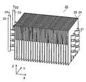
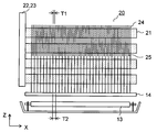
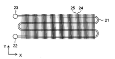
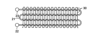
図2、図3、図4は蒸発器20の部分斜視図、正面図及び上面図を示している。蒸発器20は鉛直に配される冷媒管22、23の間に左右方向のX方向(第1方向)に延びる複数の冷媒管21が設けられる。冷媒管22から矢印D1に示すように冷媒が流入して冷媒管23から矢印D2に示すように冷媒が流出する。冷媒管21及び冷媒管22、23はアルミニウムや銅などの良熱伝導性の材質により形成される。
冷媒管21は図5に示すように扁平断面形状を有し、対向する扁平面21bに沿って複数のマイクロチャンネル(微細通路)21aを並設した扁平多孔管に形成される。これにより、円管よりも熱交換効率の高い冷媒管21が得られる。複数の冷媒管21は上下方向のZ方向(第2方向)に複数段(本実施形態では4段)に並設される。
この時、各冷媒管21はマイクロチャンネル21aの並設方向が上下方向になるように配置される。これにより、第1冷気通路7(図1参照)を上下方向に流通する気流の圧力損失を低くすることができる。また、冷媒管21は水平面内でW字状に蛇行して前後方向のY方向に複数列(本実施形態では4列)に形成され、一端を冷媒管22に連結して他端を冷媒管23に連結する。
扁平多孔管に形成された冷媒管21には複数の薄板状の放熱フィン24、25が取り付けられる。放熱フィン24、25はアルミニウム等の金属によって同様の形状に形成され、上下方向(第2方向)の長さが異なっている。放熱フィン24、25は交互に左右方向に所定間隔で並べられ、上下方向に延びて配される。これにより、第1冷気通路7(図1参照)を上下方向に流通する気流の圧力損失を低くすることができる。
放熱フィン24は最上段から最下段までの4段の冷媒管21に固着される。放熱フィン24(第1の放熱フィン)よりも上下方向に短い放熱フィン25(第2の放熱フィン)は上部の2段の冷媒管21に固着される。これにより、下部の2段のフィンピッチT2は上部の2段のフィンピッチT1よりも大きく(本実施形態では2倍)形成される。
戻り口7b(図2参照)は蒸発器20の下部に面して配され、戻り口7c(図2参照)は蒸発器20よりも下方の第1冷気通路7内に臨んで配される。このため、戻り口7b、7cから蒸発器20に戻る冷気に含まれた水分によって蒸発器20の下部が着霜し易くなる。従って、蒸発器20の下部のフィンピッチT2を大きくすることにより、蒸発器20の着霜による目詰まりを抑制することができる。また、蒸発器20の上部のフィンピッチT1を小さくすることにより、蒸発器20の熱交換面積を大きくすることができる。
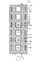
図6、図7は蒸発器20の側面断面図を示している。図6は放熱フィン24に面した断面を示しており、図7は放熱フィン25に面した断面を示している。放熱フィン24、25には上下方向に延びて下端を開放する複数の溝部24a、25aが設けられ、櫛状に形成される。放熱フィン24、25は冷媒管21に対して上方から溝部24a、25aに冷媒管21を挿通し、ロウ付け等によって固着される。尚、図6、図7において解りやすくするために溝部24a、25aと扁平面21bとの間に隙間を設けているが、放熱フィン24、25はロウ付け等によって扁平面21bに隙間なく取り付けられる。
このため、各冷媒管21の上下の端面は放熱フィン24、25に対して離れるが、4段の冷媒管21の扁平面21bが溝部24aの両側面を介して放熱フィン24に接する。また、放熱フィン25は2段の冷媒管21の扁平面21bに接する。これにより、放熱フィン24、25と冷媒管21との接触面積を大きくすることができる。従って、蒸発器20の熱交換効率を向上することができる。
また、除霜運転時に除霜ヒータ13の熱が上下の冷媒管21に跨がる放熱フィン24を介して蒸発器20の上部に伝熱される。このため、放熱フィン24を介した伝熱量を大きくすることができ、除霜効率を向上することができる。また、放熱フィン24の下端はヒータカバー14に接して配される。これにより、ヒータカバー14から直接放熱フィン24に伝熱された熱は放熱フィン24によって蒸発器20の上部にまで効率よく伝熱されるので、除霜効率をより向上することができる。
また、放熱フィン24、25は冷媒管21の扁平面21bに接する接続部分S1と、上下方向に隣接する接続部分S1間の伝熱を行う伝熱部分S2とを有する。放熱フィン24、25は上方から挿入されるため、蒸発器20の上端に位置する冷媒管21の扁平面21bに対して接続部分S1を有する。
この時、接続部分S1の上下方向の長さの和は伝熱部分S2の上下方向の長さの和よりも大きくなっている。除霜運転時には放熱フィン24、25を介した伝熱に加えて冷媒管21を介した伝熱も行われる。このため、冷媒管21を接近させて伝熱部分S2を小さくすることにより上下方向の熱伝導性が向上するので、放熱フィン24、25間の着霜をより迅速に除霜して除霜効率をより向上することができる。
本実施形態によると、左右方向(第1方向)に延びて上下方向(第2方向)に並ぶ複数の冷媒管21が上下方向にマイクロチャンネル21aを並設した扁平多孔管により形成される。また、放熱フィン24、25が上下に隣り合う冷媒管21の扁平面21bに接する接続部分S1と、接続部分S1間の伝熱を行う伝熱部分S2とを有する。
これにより、冷媒管21と放熱フィン24、25との接続部分S1が冷媒管21の扁平面21bであるため、冷媒管21と放熱フィン24、25との接触面積を大きくすることができ、蒸発器20の熱交換効率を向上することができる。また、放熱フィン24、25の伝熱部分S2によって除霜運転時に放熱フィン24、25を介した伝熱量を大きくすることができ、除霜効率を向上することができる。
また、左右方向(第1方向)に並設される放熱フィン24(第1の放熱フィン)の間に放熱フィン24よりも上下方向(第2方向)の長さが短い放熱フィン25(第2の放熱フィン)が配置される。これにより、蒸発器20の下部の着霜による目詰まりを抑制できるとともに、熱交換面積を大きくすることができる。
尚、放熱フィン24、25が交互に配置されているが、第1方向の両端に配置した放熱フィン24間に放熱フィン25を配置してもよく、第1方向の両端に配置した放熱フィン25間に放熱フィン24を配置してもよい。
また、放熱フィン24の下端がヒータカバー14に接するため、ヒータカバー14から直接放熱フィン24に伝熱して除霜効率をより向上することができる。
また、接続部分S1の上下方向の長さの和が伝熱部分S2の上下方向の長さの和よりも大きいので、冷媒管21の伝熱によって放熱フィン24、25の着霜をより迅速に除霜して除霜効率をより向上することができる。
また、放熱フィン24、25が一端を開口して上下方向に延びる溝部24a、25aを有し、溝部24a、25aの両側面が複数の冷媒管21の扁平面21bに接する。これにより、冷媒管21の上方から放熱フィン24、25を挿入し、冷媒管21に対して接触面積の大きい放熱フィン24、25を有した蒸発器20を容易に実現することができる。
尚、放熱フィン24の開口端は下端に限らず上端であってもよく、この場合は放熱フィン24を冷媒管21の下方から挿入してもよい。放熱フィン24の開口端を上端に設けた場合には、放熱フィン24は下端で前後方向のY方向に連結している状態とすることができる。このため、放熱フィン24の下端に取り付けられたヒータカバー14の熱を前後方向にもムラ無く伝熱することができ、除霜効率をより向上することができる。
<第2実施形態>
次に、図8、図9は第2実施形態の冷蔵庫1の蒸発器20の正面図及び部分斜視図を示している。説明の便宜上、前述の図1~図6に示す第1実施形態と同様の部分には同一の符号を付している。本実施形態の蒸発器20は第1実施形態に対して冷媒管21の段数が異なり、異なる形状の放熱フィン26、27、28が設けられる。その他の部分は第1実施形態と同様であり、蒸発器20の上面図は前述の図4と同様である。
次に、図8、図9は第2実施形態の冷蔵庫1の蒸発器20の正面図及び部分斜視図を示している。説明の便宜上、前述の図1~図6に示す第1実施形態と同様の部分には同一の符号を付している。本実施形態の蒸発器20は第1実施形態に対して冷媒管21の段数が異なり、異なる形状の放熱フィン26、27、28が設けられる。その他の部分は第1実施形態と同様であり、蒸発器20の上面図は前述の図4と同様である。
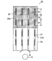
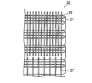
冷媒管22、23の間に配される冷媒管21は上下方向(第2方向)に6段に並設される。冷媒管21に取付けられる放熱フィン26、27、28は薄板状に形成される。放熱フィン26は最上段から3段の冷媒管21に固着される。放熱フィン27は放熱フィン26との間に間隔dを有して上から3段目から5段目の冷媒管21に固着される。放熱フィン28は放熱フィン27との間に間隔dを有して上から5段目及び6段目の冷媒管21に固着される。
放熱フィン27のフィンピッチT2は放熱フィン26のフィンピッチT1以上に(本実施形態では2倍)形成される。また、放熱フィン28のフィンピッチT3は放熱フィン27のフィンピッチT2以上に(本実施形態では2倍)形成される。これにより、蒸発器20の着霜による目詰まりを抑制できるとともに、蒸発器20の熱交換面積を大きくすることができる。
図10は蒸発器20の側面断面図を示している。放熱フィン26には矩形に形成される複数の挿通孔26c、26dが設けられる。挿通孔26dは放熱フィン26の前後方向の中央部に配され、各冷媒管21の前後方向に隣接する2列に嵌合する。挿通孔26cは挿通孔26dの前後にそれぞれ配され、各冷媒管21の前後方向の1列に嵌合する。
放熱フィン26の下端には溝部26a、26bが設けられる。溝部26bは放熱フィン26の前後方向の中央部に配され、各冷媒管21の前後方向に隣接する2列に嵌合する。溝部26aは溝部26bの前後にそれぞれ配され、各冷媒管21の前後方向の1列に嵌合する。挿通孔26c、26d及び溝部26a、26bのコーナーを冷媒管21の外形に沿って曲面に形成してもよい。
放熱フィン26は冷媒管22、23に取り付ける前の冷媒管21に対して左右の一端から挿通孔26c、26d及び溝部26a、26bに冷媒管21を挿通してロウ付けや圧入等によって固着される。尚、図10において解りやすくするために挿通孔26c、26d及び溝部26a、26bと扁平面21bとの間に隙間を設けているが、放熱フィン26はロウ付けや圧入等によって扁平面21bに隙間なく取り付けられる。
このため、上から2段の冷媒管21の前端と後端の列は扁平面21bが挿通孔26cの両側面を介して放熱フィン26に接する。上から2段の冷媒管21の中央の2列は外側の扁平面21bが挿通孔26dの側面を介して放熱フィン26に接する。また、上から3段目の冷媒管21の前端と後端の列は扁平面21bの上部が溝部26aの両側面を介して放熱フィン26に接する。上から3段目の冷媒管21の中央の2列は外側の扁平面21bの上部が溝部26bの側面を介して放熱フィン26に接する。
放熱フィン26と同様に放熱フィン27は挿通孔27c、27d及び溝部27a、27bが設けられ、放熱フィン28は挿通孔28c、28d及び溝部28a、28bが設けられる。溝部27a、27bは放熱フィン27の上端及び下端に形成され、溝部28a、28bは放熱フィン27の上端に形成される。
これにより、上から3段目の冷媒管21の前端と後端の列は扁平面21bの下部が溝部27aの両側面を介して放熱フィン27に接する。上から3段目の冷媒管21の中央の2列は外側の扁平面21bの下部が溝部27bの側面を介して放熱フィン27に接する。上から4段目の冷媒管21の前端と後端の列は扁平面21bが挿通孔27cの両側面を介して放熱フィン27に接する。上から4段目の冷媒管21の中央の2列は外側の扁平面21bが挿通孔27dの側面を介して放熱フィン27に接する。
上から5段目の冷媒管21の前端と後端の列は扁平面21bの上部が溝部27aの両側面を介して放熱フィン27に接する。上から5段目の冷媒管21の中央の2列は外側の扁平面21bの上部が溝部27bの側面を介して放熱フィン27に接する。
上から5段目の冷媒管21の前端と後端の列は扁平面21bの下部が溝部28aの両側面を介して放熱フィン28に接する。上から5段目の冷媒管21の中央の2列は外側の扁平面21bの下部が溝部28bの側面を介して放熱フィン28に接する。上から6段目の冷媒管21の前端と後端の列は扁平面21bが挿通孔28cの両側面を介して放熱フィン28に接する。上から6段目の冷媒管21の中央の2列は外側の扁平面21bが挿通孔28dの側面を介して放熱フィン28に接する。
即ち、上から3段目の冷媒管21の扁平面21b上から上下方向(第2方向)の一方に放熱フィン26(第1の放熱フィン)が延び、他方に放熱フィン27(第2の放熱フィン)が延びる。また、上から5段目の冷媒管21の扁平面21b上から上下方向(第2方向)の一方に放熱フィン27(第1の放熱フィン)が延び、他方に放熱フィン28(第2の放熱フィン)が延びる。
これにより、放熱フィン26、27、28の上下方向の端部も冷媒管21と接触させることができ、放熱フィン26、27、28と冷媒管21との接触面積を大きくすることができる。また、上下に隣接する放熱フィン26、27、28が溝部26a、26b、27a、27b、28a、28bによって同一の冷媒管21を介して熱伝導的に接合される。これにより、除霜運転時に放熱フィン26、27、28及び冷媒管21を介した伝熱量を大きくすることができ、除霜効率を向上することができる。
また、放熱フィン26、27、28は冷媒管21に対して前後方向に重なる接続部分S1と、上下方向に隣接する接続部分S1間に形成される伝熱部分S2とを有する。この時、接続部分S1の上下方向の長さの和は伝熱部分S2の上下方向の長さの和よりも大きくなっている。これにより、除霜運転時には接続部分S1においては放熱フィン26、27、28を介した伝熱に加えて冷媒管21を介した伝熱も行われるので、上下方向の熱伝導率が向上する。従って、放熱フィン26、27、28の着霜をより迅速に除霜して効率をより向上することができる。また、除霜運転時の熱が接続部分S1を介して冷媒管21に伝わりやすくなるため、冷媒管21の着霜もより迅速に除霜して除霜効率をより向上することができる。
本実施形態によると、第1実施形態と同様の効果を得ることができる。また、所定の冷媒管21の扁平面21b上から上下方向の一方に第1の放熱フィン(放熱フィン26または放熱フィン27)が延び、他方に第2の放熱フィン(放熱フィン27または放熱フィン28)が延びる。これにより、第1の放熱フィン及び第2の放熱フィンの上下方向の端部も冷媒管21と接触させることができる。従って、冷媒管21に対して接触面積の大きい放熱フィン26、27、28を有した蒸発器20を容易に実現することができる。
また、放熱フィン26(第1の放熱フィン)の左右方向(第1方向)の間隔が放熱フィン26の下方の放熱フィン27(第2の放熱フィン)の左右方向の間隔と同じまたは狭くなっている。また、放熱フィン27(第1の放熱フィン)の左右方向の間隔が放熱フィン26の下方の放熱フィン28(第2の放熱フィン)の左右方向の間隔と同じまたは狭くなっている。これにより、蒸発器20の下部の着霜による目詰まりを抑制できるとともに、熱交換面積を大きくすることができる。
そして、放熱フィン26(第1の放熱フィン)と放熱フィン26の下方の放熱フィン27(第2の放熱フィン)とは、所定の冷媒管21の扁平面21b上において上下方向(第2方向)に間隔dを有して配置される。また、放熱フィン27(第1の放熱フィン)と放熱フィン27の下方の放熱フィン28(第2の放熱フィン)とは、所定の冷媒管21の扁平面21b上において上下方向(第2方向)に間隔dを有して配置される。
第1の放熱フィンと第2の放熱フィンとが接近して隙間が狭くなると、その隙間を跨ぐ着霜が発生しやすくなるため上下方向の空気の流通を阻害する目詰りとなる。第2の放熱フィンの左右方向(第1方向)の間隔が第1の放熱フィンの左右方向の間隔の整数倍の場合には、第1、第2の放熱フィンと第2の放熱フィンとを左右方向にずらして配置することで両者間の隙間を大きく形成できる。
これに対して、第2の放熱フィンの左右方向(第1方向)の間隔が第1の放熱フィンの左右方向の間隔の非整数倍の場合には、両者が接近した位置で上記の目詰まりを生じる。このため、間隔dを設けることにより、第1の放熱フィンと第2の放熱フィンとの間に間隔d以上の隙間を形成し、狭い隙間の発生を防止することができる。間隔dは3mm以上に形成すると望ましい。
この時、間隔dは冷媒管21の扁平面21b上に形成さているので、間隔dによって第1の放熱フィンと第2の放熱フィンとの間の伝熱が低下したとしても両者間には冷媒管21の扁平面21bが跨がる。このため、放熱フィンと冷媒管21の扁平面21bとのリレーによって効率よく上下方向に伝熱することができる。
また、上下方向に隣接する放熱フィン26、27、28が同一の冷媒管21の上下方向の両端にそれぞれ嵌合して扁平面21bに接する溝部26a、26b、27a、27b、28a、28bを有する。これにより、放熱フィン26、27、28が冷媒管21を介して熱伝導的に結合され、除霜効率を向上することができる。
<第3実施形態>
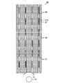
次に、図11は第3実施形態の冷蔵庫1の蒸発器20の正面図を示している。また、図12、図13、図14はそれぞれ図11のA-A断面図、B-B断面図及びC-C断面図を示している。説明の便宜上、前述の図8~図10に示す第2実施形態と同様の部分には同一の符号を付している。本実施形態の蒸発器20は第2実施形態に対して異なる形状の放熱フィン29、30、31が設けられる。その他の部分は第2実施形態と同様である。
次に、図11は第3実施形態の冷蔵庫1の蒸発器20の正面図を示している。また、図12、図13、図14はそれぞれ図11のA-A断面図、B-B断面図及びC-C断面図を示している。説明の便宜上、前述の図8~図10に示す第2実施形態と同様の部分には同一の符号を付している。本実施形態の蒸発器20は第2実施形態に対して異なる形状の放熱フィン29、30、31が設けられる。その他の部分は第2実施形態と同様である。
放熱フィン29、30、31は図15に示すように、金属板を矩形波状または台形波状に曲折したコルゲートフィンにより形成される。放熱フィン29、30、31を正弦波状のコルゲートフィンにより形成してもよいが、矩形波状または台形波状に形成すると冷媒管21との接触面積を大きくできるためより望ましい。
放熱フィン29、30、31は前後方向に複数列の冷媒管21の間及び外側に複数設けられる。放熱フィン29は最上段から3段の冷媒管21に固着される。放熱フィン30は上から3段目から5段目の冷媒管21に固着される。放熱フィン31は上から5段目及び6段目の冷媒管21に固着される。
放熱フィン30のフィンピッチT2は放熱フィン29のフィンピッチT1以上に(本実施形態では2倍)形成される。また、放熱フィン31のフィンピッチT3は放熱フィン30のフィンピッチT2以上に(本実施形態では2倍)形成される。これにより、蒸発器20の着霜による目詰まりを抑制できるとともに、蒸発器20の熱交換面積を大きくすることができる。
図16は蒸発器20の側面断面図を示している。放熱フィン29、30、31は左右方向または上下方向から冷媒管21の各列間及び外側に配され、ロウ付け等によって固着される。これにより、放熱フィン29、30、31はそれぞれ上下に並ぶ複数の冷媒管21の扁平面21bに接して取り付けられる。尚、図16において解りやすくするために放熱フィン29、30、31と扁平面21bとの間に隙間を設けているが、放熱フィン29、30、31はロウ付け等によって扁平面21bに隙間なく取り付けられる。
また、上から3段目の冷媒管21の上部は放熱フィン29に接し、下部は放熱フィン30に接する。上から5段目の冷媒管21の上部は放熱フィン30に接し、下部は放熱フィン31に接する。これにより、上下に隣接する放熱フィン29、30が同一の冷媒管21を介して熱伝導的に接合され、放熱フィン30、31が同一の冷媒管21を介して熱伝導的に接合される。従って、除霜運転時に放熱フィン29、30、31及び冷媒管21を介した伝熱量を大きくすることができ、除霜効率を向上することができる。
そして、放熱フィン29と放熱フィン30とは、上から3段目の冷媒管21の扁平面21b上において上下方向(第2方向)に間隔dを有して配置される。同様に、放熱フィン30と放熱フィン31とは、上から5段目の冷媒管21の扁平面21b上において上下方向(第2方向)に間隔dを有して配置される。これにより、放熱フィン29と放熱フィン30との間及び放熱フィン30と放熱フィン31との間には間隔d以上の隙間が形成される。従って、間隔dよりも狭い隙間は形成されなくなり、狭い隙間を跨ぐ着霜を防いで目詰りを防止することができる。
本実施形態によると、第2実施形態と同様の効果を得ることができる。また、放熱フィン29、30、31がコルゲートフィンにより形成されるので、冷媒管21の扁平面21bと接触面積の大きい放熱フィン29、30、31を有した蒸発器20を容易に実現することができる。
尚、第2実施形態と第3実施形態とは排他的ではなく、混在して実施することもできる。例えば、第2実施形態における放熱フィン26、27、28のいずれかもしくは全てを前後方向に分離してもよく、前後方向に中央となる2列の冷媒管21の間に第3実施形態の放熱フィン29、30、31を配置してもよい。
このようにすることで、前後方向に中央となる2列の冷媒管21は、外側の扁平面21bが第2実施形態における放熱フィンと接し、内側の扁平面21bが第2実施形態における放熱フィンと接することができる。これにより、冷媒管21と放熱フィンとの熱交換効率をさらに向上させることができる。
また、第3実施形態における放熱フィン29、30、31のいずれかもしくは全てをコルゲートフィンではなく、第2実施形態のような薄板状のフィンとしてもよい。さらに、上記の様々な実施形態を場所により混在させてもよい。
本発明によると、冷気を生成する蒸発器及びそれを用いた冷蔵庫に利用することができる。
1 冷蔵庫
2 キャビネット
3 冷蔵室
3a、4a、5a 扉
4 冷凍室
5 野菜室
6 機械室
7 第1冷気通路
8 第2冷気通路
10 圧縮機
11 蒸発器
12 送風機
13 除霜ヒータ
14 ヒータカバー
15 除霜トレイ
16 ドレンパイプ
17 蒸発皿
20 蒸発器
21、22、23 冷媒管
21a マイクロチャンネル
21b 扁平面
24~31 放熱フィン
24a、26a、26b、27a、27b、28a、28b 溝部
24c、24d、26c、26d、27c、27d、28c、28d 挿通孔
2 キャビネット
3 冷蔵室
3a、4a、5a 扉
4 冷凍室
5 野菜室
6 機械室
7 第1冷気通路
8 第2冷気通路
10 圧縮機
11 蒸発器
12 送風機
13 除霜ヒータ
14 ヒータカバー
15 除霜トレイ
16 ドレンパイプ
17 蒸発皿
20 蒸発器
21、22、23 冷媒管
21a マイクロチャンネル
21b 扁平面
24~31 放熱フィン
24a、26a、26b、27a、27b、28a、28b 溝部
24c、24d、26c、26d、27c、27d、28c、28d 挿通孔
Claims (5)
- 第1方向に延びて冷媒が流通するとともに第1方向に直交する第2方向に並設して端部で連結される複数の冷媒管と、前記冷媒管に接する放熱フィンとを備えた蒸発器において、前記冷媒管は扁平断面形状を有しており対向する扁平面に沿って第2方向に複数のマイクロチャンネルを並設した扁平多孔管により形成され、前記放熱フィンは、第2方向に延在するとともに第2方向に隣り合う前記冷媒管の前記扁平面にそれぞれ接する接続部分と、前記接続部分の間に位置して前記接続部分間の伝熱を行う伝熱部分とを有することを特徴とする蒸発器。
- 前記放熱フィンは、所定の前記冷媒管の前記扁平面上から第2方向の一方の方向に延びる第1の放熱フィンと、他方の方向に延びる第2の放熱フィンとを含み、
第1の放熱フィンと第2の放熱フィンとは、該扁平面上において第2方向に間隔を有して配置されていることを特徴とする請求項1に記載の蒸発器。 - 前記放熱フィンは、第2方向に隣り合う前記冷媒管の前記扁平面上に前記接続部分を有する第1の放熱フィンと、第1の放熱フィンよりも第2方向における長さが短い第2の放熱フィンとを含み、
第1方向において、第2の放熱フィンが第1の放熱フィンの間に、または第1の放熱フィンが第2の放熱フィンの間に配置されていることを特徴とする請求項1に記載の蒸発器。 - 請求項2に記載の蒸発器の第2方向を上下方向に配し、前記蒸発器の下方に配されて前記蒸発器を除霜する除霜ヒータと、前記除霜ヒータと前記蒸発器との間に配されるヒータカバーとを備え、
第1の放熱フィンの第1方向における配置間隔は、第2の放熱フィンの第1方向における配置間隔と同じまたは狭い間隔で配置されており、
第1の放熱フィンは第2の放熱フィンよりも上側に配置されており、
第2の放熱フィンの下端部が前記ヒータカバーに接することを特徴とする冷蔵庫。 - 請求項3に記載の蒸発器の第2方向を上下方向に配し、前記蒸発器の下方に配される前記蒸発器を除霜する除霜ヒータと、前記除霜ヒータと前記蒸発器との間に配されるヒータカバーとを備え、
第1の放熱フィンは前記蒸発器の上端に位置する前記冷媒管の前記扁平面に対して前記接続部分を有し、第1の放熱フィンの下端部が前記ヒータカバーに接することを特徴とする冷蔵庫。
Applications Claiming Priority (2)
| Application Number | Priority Date | Filing Date | Title |
|---|---|---|---|
| JP2013-030075 | 2013-02-19 | ||
| JP2013030075A JP2014159891A (ja) | 2013-02-19 | 2013-02-19 | 蒸発器及びそれを用いた冷蔵庫 |
Publications (1)
| Publication Number | Publication Date |
|---|---|
| WO2014129318A1 true WO2014129318A1 (ja) | 2014-08-28 |
Family
ID=51391114
Family Applications (1)
| Application Number | Title | Priority Date | Filing Date |
|---|---|---|---|
| PCT/JP2014/052841 Ceased WO2014129318A1 (ja) | 2013-02-19 | 2014-02-07 | 蒸発器及びそれを用いた冷蔵庫 |
Country Status (2)
| Country | Link |
|---|---|
| JP (1) | JP2014159891A (ja) |
| WO (1) | WO2014129318A1 (ja) |
Cited By (10)
| Publication number | Priority date | Publication date | Assignee | Title |
|---|---|---|---|---|
| FR3026477A1 (fr) * | 2014-09-25 | 2016-04-01 | Valeo Systemes Thermiques | Echangeur thermique a degivrage ameliore |
| EP3076107A1 (en) * | 2015-04-01 | 2016-10-05 | Samsung Electronics Co., Ltd. | Refrigerator and heat exchanger used therein |
| CN109237841A (zh) * | 2017-07-10 | 2019-01-18 | 美的集团股份有限公司 | 换热模块、换热器及冰箱 |
| CN111102766A (zh) * | 2018-10-29 | 2020-05-05 | 博西华电器(江苏)有限公司 | 微通道换热器及制冷器具 |
| CN113739452A (zh) * | 2020-05-29 | 2021-12-03 | 青岛海尔电冰箱有限公司 | 蒸发器及具有其的制冷装置 |
| CN113739453A (zh) * | 2020-05-29 | 2021-12-03 | 青岛海尔电冰箱有限公司 | 蒸发器及具有其的冰箱 |
| CN115315602A (zh) * | 2020-05-29 | 2022-11-08 | 松下知识产权经营株式会社 | 热交换器和冷藏库 |
| CN116086047A (zh) * | 2023-01-16 | 2023-05-09 | 合肥华凌股份有限公司 | 一种换热装置及冰箱 |
| US20240240877A1 (en) * | 2021-09-30 | 2024-07-18 | Daikin Industries, Ltd. | Heat exchanger |
| EP4530568A1 (en) * | 2023-09-27 | 2025-04-02 | Danfoss A/S | Heat exchanger, bent heat exchanger and air conditioning system |
Families Citing this family (2)
| Publication number | Priority date | Publication date | Assignee | Title |
|---|---|---|---|---|
| CN104949398A (zh) * | 2015-06-16 | 2015-09-30 | 江苏启江实业有限公司 | 间冷冰箱用扁管穿片式微通道蒸发器 |
| CN104864635A (zh) * | 2015-06-16 | 2015-08-26 | 江苏启江实业有限公司 | 直冷冰箱用扁管穿片式微通道蒸发器 |
Citations (6)
| Publication number | Priority date | Publication date | Assignee | Title |
|---|---|---|---|---|
| JPH05306877A (ja) * | 1992-04-30 | 1993-11-19 | Matsushita Refrig Co Ltd | 冷凍冷蔵庫 |
| WO2000000778A2 (en) * | 1998-06-12 | 2000-01-06 | S.C. Romradiatoare S.A. | Radiating elements for heat exchangers and method of manufacturing such heat exchangers |
| JP2003279291A (ja) * | 2002-03-26 | 2003-10-02 | Toyo Radiator Co Ltd | 熱交換器 |
| JP2007192441A (ja) * | 2006-01-18 | 2007-08-02 | Matsushita Electric Ind Co Ltd | 放熱器、放熱器の製造方法及びそれを備えた冷却装置 |
| JP2009092261A (ja) * | 2007-10-04 | 2009-04-30 | Hoshizaki Electric Co Ltd | 冷却貯蔵庫 |
| JP2010286187A (ja) * | 2009-06-12 | 2010-12-24 | Mitsubishi Electric Corp | 扁平管熱交換器 |
-
2013
- 2013-02-19 JP JP2013030075A patent/JP2014159891A/ja active Pending
-
2014
- 2014-02-07 WO PCT/JP2014/052841 patent/WO2014129318A1/ja not_active Ceased
Patent Citations (6)
| Publication number | Priority date | Publication date | Assignee | Title |
|---|---|---|---|---|
| JPH05306877A (ja) * | 1992-04-30 | 1993-11-19 | Matsushita Refrig Co Ltd | 冷凍冷蔵庫 |
| WO2000000778A2 (en) * | 1998-06-12 | 2000-01-06 | S.C. Romradiatoare S.A. | Radiating elements for heat exchangers and method of manufacturing such heat exchangers |
| JP2003279291A (ja) * | 2002-03-26 | 2003-10-02 | Toyo Radiator Co Ltd | 熱交換器 |
| JP2007192441A (ja) * | 2006-01-18 | 2007-08-02 | Matsushita Electric Ind Co Ltd | 放熱器、放熱器の製造方法及びそれを備えた冷却装置 |
| JP2009092261A (ja) * | 2007-10-04 | 2009-04-30 | Hoshizaki Electric Co Ltd | 冷却貯蔵庫 |
| JP2010286187A (ja) * | 2009-06-12 | 2010-12-24 | Mitsubishi Electric Corp | 扁平管熱交換器 |
Cited By (13)
| Publication number | Priority date | Publication date | Assignee | Title |
|---|---|---|---|---|
| FR3026477A1 (fr) * | 2014-09-25 | 2016-04-01 | Valeo Systemes Thermiques | Echangeur thermique a degivrage ameliore |
| EP3076107A1 (en) * | 2015-04-01 | 2016-10-05 | Samsung Electronics Co., Ltd. | Refrigerator and heat exchanger used therein |
| CN109237841A (zh) * | 2017-07-10 | 2019-01-18 | 美的集团股份有限公司 | 换热模块、换热器及冰箱 |
| CN111102766A (zh) * | 2018-10-29 | 2020-05-05 | 博西华电器(江苏)有限公司 | 微通道换热器及制冷器具 |
| WO2020089162A1 (en) * | 2018-10-29 | 2020-05-07 | BSH Hausgeräte GmbH | Micro-channel heat exchanger and refrigeration appliance |
| CN113739453A (zh) * | 2020-05-29 | 2021-12-03 | 青岛海尔电冰箱有限公司 | 蒸发器及具有其的冰箱 |
| CN113739452A (zh) * | 2020-05-29 | 2021-12-03 | 青岛海尔电冰箱有限公司 | 蒸发器及具有其的制冷装置 |
| CN115315602A (zh) * | 2020-05-29 | 2022-11-08 | 松下知识产权经营株式会社 | 热交换器和冷藏库 |
| CN113739453B (zh) * | 2020-05-29 | 2023-11-03 | 青岛海尔电冰箱有限公司 | 蒸发器及具有其的冰箱 |
| CN113739452B (zh) * | 2020-05-29 | 2023-11-07 | 青岛海尔电冰箱有限公司 | 蒸发器及具有其的制冷装置 |
| US20240240877A1 (en) * | 2021-09-30 | 2024-07-18 | Daikin Industries, Ltd. | Heat exchanger |
| CN116086047A (zh) * | 2023-01-16 | 2023-05-09 | 合肥华凌股份有限公司 | 一种换热装置及冰箱 |
| EP4530568A1 (en) * | 2023-09-27 | 2025-04-02 | Danfoss A/S | Heat exchanger, bent heat exchanger and air conditioning system |
Also Published As
| Publication number | Publication date |
|---|---|
| JP2014159891A (ja) | 2014-09-04 |
Similar Documents
| Publication | Publication Date | Title |
|---|---|---|
| WO2014129318A1 (ja) | 蒸発器及びそれを用いた冷蔵庫 | |
| EP2868999B1 (en) | Refrigeration cycle of refrigerator | |
| KR102174510B1 (ko) | 냉장고의 냉각 사이클 | |
| JP2016003831A (ja) | 冷蔵庫 | |
| JP5847198B2 (ja) | 冷蔵庫 | |
| CN106500437A (zh) | 冰箱的风道系统和具有其的冰箱 | |
| JP2011158250A (ja) | 熱交換器及びこの熱交換器を搭載した冷凍冷蔵庫 | |
| KR102707771B1 (ko) | 응축기 및 이를 구비한 냉장고 | |
| JP7644572B2 (ja) | 冷蔵庫 | |
| JP2014020736A (ja) | 冷蔵庫 | |
| KR100593086B1 (ko) | 열교환 효율이 향상된 냉장고 | |
| TWI722397B (zh) | 冰箱 | |
| JP4762266B2 (ja) | 熱交換器及びこの熱交換器を搭載した冷凍冷蔵庫 | |
| JP7788614B2 (ja) | 冷蔵庫 | |
| CN110671863A (zh) | 蒸发器和具有蒸发器的冰箱 | |
| KR20110087917A (ko) | 냉장고 | |
| JP2014013111A (ja) | 冷蔵庫 | |
| CN102914098A (zh) | 冰箱用蒸发器及具有其的冰箱 | |
| JP7129372B2 (ja) | 冷蔵装置 | |
| JP5020159B2 (ja) | 熱交換器、冷蔵庫及び空調装置 | |
| JP7759536B2 (ja) | 冷蔵庫 | |
| CN118776207A (zh) | Vis制冷机的热学改进 | |
| JP5553101B2 (ja) | 冷却器および保冷庫 | |
| JP2014052094A (ja) | 冷蔵庫 | |
| JP2003121090A (ja) | 熱交換器およびこれを用いた冷蔵庫 |
Legal Events
| Date | Code | Title | Description |
|---|---|---|---|
| 121 | Ep: the epo has been informed by wipo that ep was designated in this application |
Ref document number: 14753837 Country of ref document: EP Kind code of ref document: A1 |
|
| NENP | Non-entry into the national phase |
Ref country code: DE |
|
| 122 | Ep: pct application non-entry in european phase |
Ref document number: 14753837 Country of ref document: EP Kind code of ref document: A1 |