WO2014129296A1 - 車輌装備品制御システム - Google Patents
車輌装備品制御システム Download PDFInfo
- Publication number
- WO2014129296A1 WO2014129296A1 PCT/JP2014/052404 JP2014052404W WO2014129296A1 WO 2014129296 A1 WO2014129296 A1 WO 2014129296A1 JP 2014052404 W JP2014052404 W JP 2014052404W WO 2014129296 A1 WO2014129296 A1 WO 2014129296A1
- Authority
- WO
- WIPO (PCT)
- Prior art keywords
- vehicle equipment
- unit
- usage mode
- power
- mode
- Prior art date
- Legal status (The legal status is an assumption and is not a legal conclusion. Google has not performed a legal analysis and makes no representation as to the accuracy of the status listed.)
- Ceased
Links
Images





Classifications
-
- B—PERFORMING OPERATIONS; TRANSPORTING
- B60—VEHICLES IN GENERAL
- B60R—VEHICLES, VEHICLE FITTINGS, OR VEHICLE PARTS, NOT OTHERWISE PROVIDED FOR
- B60R16/00—Electric or fluid circuits specially adapted for vehicles and not otherwise provided for; Arrangement of elements of electric or fluid circuits specially adapted for vehicles and not otherwise provided for
- B60R16/02—Electric or fluid circuits specially adapted for vehicles and not otherwise provided for; Arrangement of elements of electric or fluid circuits specially adapted for vehicles and not otherwise provided for electric constitutive elements
- B60R16/023—Electric or fluid circuits specially adapted for vehicles and not otherwise provided for; Arrangement of elements of electric or fluid circuits specially adapted for vehicles and not otherwise provided for electric constitutive elements for transmission of signals between vehicle parts or subsystems
Definitions
- the present invention relates to a vehicle equipment control system that controls the usage of vehicle equipment.
- Patent Document 1 has a drive device for changing the position of a seat, etc., a keyless remote controller carried by each occupant, and a storage unit for storing position information of the seat, etc.
- a conventional vehicle equipment control system comprising: a control device that performs control for automatically setting a seat or the like to a stored position by calling up position information stored in the storage unit based on a lock operation to operate the drive device Is described.
- a unique remote controller ID is assigned to each keyless remote controller, and position information such as a sheet is stored in the storage unit in association with the remote controller ID.
- a plurality of occupants who use the vehicle carry keyless remote controllers each with a different remote controller ID.
- the control device acquires the remote control ID, the control device reads position information stored in the storage unit in association with the remote control ID, and performs control to automatically set the position of the sheet or the like.
- the keyless remote control operates on battery, so if the battery runs out, automatic setting of vehicle equipment cannot be used. In addition, when a large number of passengers use one vehicle, a large number of keyless remote controllers have to be prepared, and the labor for battery replacement increases.
- an operation switch for adjusting and changing the usage mode of the vehicle equipment is provided, and a wire harness for electrically connecting the operation switch and the control device.
- a wire harness for electrically connecting the operation switch and the control device.
- the present invention has been made in view of such circumstances, and it is possible to set the usage mode of the vehicle equipment by wirelessly transmitting the operation signal using the generated electric power, and further to save the wire harness. It is an object of the present invention to provide a vehicle equipment control system that can be realized.
- the vehicle equipment control system stores the usage mode of the vehicle equipment that can take different usage modes in association with the index information, and determines the usage mode of the vehicle equipment based on the stored usage mode.
- a vehicle equipment control system comprising: a control device that performs control to be changed; and a transmitter that receives an operation and wirelessly transmits an operation signal related to the operation to the control device, the transmitter corresponds to the index information
- An operation unit that receives an attached operation, a power generation unit that generates power by receiving power from the operation on the operation unit, and information corresponding to index information related to the operation received by the operation unit using the power generated by the power generation unit
- a transmission unit that transmits an operation signal to which the operation information is added, and the control device stores a use mode of the vehicle equipment in association with the index information, and the operation signal.
- the usage mode corresponding to the index information based on the information added to the operation signal received by the reception unit is read from the storage unit, and the usage mode of the vehicle equipment is changed to the read usage mode It has a
- the control device stores the usage mode of the vehicle equipment that can take different usage modes in association with the index information, and changes the usage mode of the vehicle equipment based on the stored usage mode.
- the transmitter receives an operation and transmits an operation signal related to the operation to the control device wirelessly.
- the transmitter receives an operation associated with the index information by the operation unit, receives power from an operation on the operation unit, generates power by the power generation unit, and uses the generated power to generate index information related to the operation received by the operation unit.
- An operation signal to which the corresponding information is added is transmitted by the transmission unit.
- the control device stores the usage mode of the vehicle equipment in the storage unit in association with the index information, and receives the operation signal by the receiving unit.
- the control unit reads the usage mode corresponding to the index information based on the information added to the operation signal received by the receiving unit from the storage unit, and performs control to change the usage mode of the vehicle equipment to the read usage mode.
- the usage mode of the vehicle equipment can be set by wirelessly transmitting the operation signal using the generated power.
- the vehicle equipment control system is characterized in that the operation unit has an operation button for each index information.
- the operation unit since the operation unit has an operation button for each index information, by operating the operation button for each index information provided in the transmitter, vehicle equipment associated with a plurality of index information
- the usage mode can be set. For example, separate index information can be assigned to each of a plurality of occupants, and the usage mode of vehicle equipment can be set for each occupant with one transmitter.
- the operation unit includes a second operation button for receiving an operation for storing a use mode of the vehicle equipment in the storage unit for each index information, and the transmission unit Transmits an operation signal to which information specifying that the usage mode corresponding to the index information related to the second operation button for which the operation has been received is stored in the storage unit, and the control unit is Based on the information added to the received operation signal, the usage mode of the vehicle equipment is stored in the storage unit.
- the operation unit has a second operation button for each index information, and the second operation button accepts an operation for storing the usage state of the vehicle equipment in the storage unit.
- the transmission unit transmits an operation signal to which information specifying that the usage mode corresponding to the index information related to the second operation button for which the operation has been received is stored in the storage unit is added.
- the control unit causes the storage unit to store the usage mode of the vehicle equipment based on the information added to the operation signal received by the receiving unit. Accordingly, by operating the second operation button for each index information provided in the transmitter, the usage mode of the vehicle equipment can be stored in the storage unit in association with the plurality of index information.
- the operation unit has a third operation button for accepting an operation for changing a use mode of the vehicle equipment, and the transmission unit is a third operation in which the operation is accepted.
- An operation signal added with information specifying that the usage mode of the vehicle equipment related to the button is changed is transmitted, and the control unit is configured to transmit the operation signal based on the information added to the operation signal received by the receiving unit. It is characterized by performing control to change the usage mode of the equipment.
- the operation unit has the third operation button, and the third operation button accepts an operation for changing the usage mode of the vehicle equipment.
- the transmission unit transmits an operation signal to which information specifying that the usage mode of the vehicle equipment related to the third operation button for which the operation has been received is to be changed is added.
- a control part performs control which changes the use aspect of a vehicle equipment based on the information added to the operation signal received by the receiving part. Thereby, the usage mode of the vehicle equipment can be changed by operating the third operation button provided in the transmitter.
- the usage mode of vehicle equipment can be changed by operating the transmitter, there is no need to provide an operation switch for changing the usage mode of the vehicle equipment on the vehicle, and the wire harness for the operation switch is reduced in line. can do.
- the vehicle equipment control system includes a plurality of the vehicle equipment, the operation unit includes a fourth operation button for receiving an operation for specifying the vehicle equipment, and the transmission unit is operated by the operation unit.
- An operation signal to which information for specifying the vehicle equipment related to the accepted fourth operation button is added is transmitted, and the control unit, based on the information added to the operation signal received by the reception unit, One vehicle equipment is identified from the vehicle equipment and controlled.
- the operation unit receives an operation for specifying the vehicle equipment by the fourth operation button.
- a transmission part transmits the operation signal which added the information which specifies the vehicle equipment which concerns on the 4th operation button by which operation was received.
- the control unit performs control by specifying one vehicle equipment item from the plurality of vehicle equipment items based on the information added to the operation signal received by the receiving unit. Accordingly, by operating the fourth operation button provided on the transmitter, it is possible to perform control for specifying one vehicle accessory from a plurality of vehicle accessories and changing the usage mode.
- the vehicle equipment control system is characterized in that the power generation unit includes a piezoelectric element that receives power by operating the operation unit to generate power.
- the power generation unit has a piezoelectric element, and the piezoelectric element generates power by receiving a force by an operation on the operation unit. Therefore, an operation signal is transmitted from the transmitter using the generated power.
- the power generation unit includes a magnetic circuit in which a magnetic flux is changed by an operation on the operation unit, and a coil in which an electromotive force is induced in accordance with a change in the magnetic flux of the magnetic circuit. It is characterized by.
- the power generation unit has a magnetic circuit and a coil, and the magnetic flux of the magnetic circuit is changed by an operation on the operation unit, and an electromotive force is induced in the coil according to the change of the magnetic flux of the magnetic circuit.
- the operation signal is transmitted from the transmitter using the electromotive force induced in the coil.
- the control device stores the usage mode of the vehicle equipment that can take different usage modes in association with the index information, and changes the usage mode of the vehicle equipment based on the stored usage mode.
- the transmitter receives an operation and transmits an operation signal related to the operation to the control device wirelessly.
- the transmitter receives an operation associated with the index information by the operation unit, receives power from an operation on the operation unit, generates power by the power generation unit, and uses the generated power to generate index information related to the operation received by the operation unit.
- An operation signal to which the corresponding information is added is transmitted by the transmission unit.
- the control device stores the usage mode of the vehicle equipment in the storage unit in association with the index information, and receives the operation signal by the receiving unit.
- the control unit reads the usage mode corresponding to the index information based on the information added to the operation signal received by the receiving unit from the storage unit, and performs control to change the usage mode of the vehicle equipment to the read usage mode. For this reason, the usage mode of the vehicle equipment can be set by transmitting the operation signal wirelessly using the generated power.
- FIG. 1 is a block diagram showing a configuration of a vehicle equipment control system 1 according to an embodiment of the present invention.
- the vehicle equipment control system 1 includes an ECU (Electronic Control Unit) 2 mounted on the vehicle 100 and a remote controller (hereinafter referred to as a remote controller) 3. Control such as selection (specification), change, storage, and reading according to the usage mode of the product.
- FIG. 1 shows door mirrors 6, 6 arranged on the left and right of a vehicle 100, a driver seat and a passenger seat as examples of vehicle equipment in which a passenger sets different usage modes according to his / her physique and preferences.
- Power assist seats (hereinafter referred to as power seats) 7 and 7 disposed in the portion are shown.
- examples of the vehicle equipment that the occupant individually sets the mode of use include a room mirror for visually recognizing the rear of the vehicle 100, a steering handle for steering, a headrest, a car navigation device, and the like.
- the door mirror 6 and the power seat 7 will be described as examples of on-vehicle equipment, but the above-described room mirror and the like can be similarly used on-vehicle equipment to which the present invention is applied.
- the ECU 2 functions as a control device in the present invention
- the remote controller 3 functions as a transmitter in the present invention.
- the door mirror 6 includes an actuator 61a that changes a vertical angle in a direction in which a mirror surface (not shown) faces, an actuator 61b that changes a horizontal angle, an angle sensor 62a that detects a vertical angle, and an angle sensor 62b that detects a horizontal angle.
- the actuators 61a and 61b are, for example, rotary motors, are connected to the ECU 2, and operate based on a drive signal from the ECU 2.
- the actuator 61a drives the direction in which the mirror surface of the door mirror 6 faces up and down
- the actuator 61b drives the direction in which the mirror surface of the door mirror 6 faces in the left and right direction.
- the angle sensors 62a and 62b are, for example, potentiometers, and are connected to the ECU 2.
- the angle sensors 62a and 62b detect the angle to be detected by a change in resistance value and output the detected angle to the ECU 2.
- the angle sensor 62a detects the vertical angle of the mirror surface of the door mirror 6, and the angle sensor 62b detects the horizontal angle of the mirror surface of the door mirror 6.
- the power seat 7 includes an actuator 71a that drives the seat to move up and down in the vertical direction, an actuator 71b that slides in the front and rear direction of the vehicle 100, a position sensor 72a that detects a position in the vertical direction, and a position sensor that detects a position in the front and rear direction. 72b.
- the actuator 71a is composed of, for example, a lift-up mechanism that moves the seat up and down and a rotary motor (not shown) that applies a driving force to the mechanism, and operates based on a drive signal from the ECU 2.
- the actuator 71b is composed of, for example, a slide mechanism that slides the seat back and forth and a rotary motor that applies a driving force to the mechanism, and operates based on a drive signal from the ECU 2.
- the position sensors 72a and 72b are, for example, potentiometers, and are connected to the ECU 2.
- the position sensors 72a and 72b detect the position of the detection target based on a change in resistance value and output the detected position to the ECU 2.
- the position sensor 72a detects the vertical position of the sheet by detecting the rotation angle of a rotary motor that drives a lift-up mechanism that moves the sheet up and down.
- the output shaft of the rotary motor rotates one or more times between the lower limit and the upper limit of the seat lift, the reduction gear is attached to the position sensor 72a so that the position sensor 72a corresponds to one rotation.
- the position sensor 72b detects the front / rear position of the seat by detecting the rotation angle of a rotary motor that drives a slide mechanism that slides the seat back and forth.
- the reduction gear is attached to the position sensor 72b so that the position sensor 72b corresponds to one rotation. .
- the ECU 2 includes a CPU (Central Processing Unit) 20, a flash memory, a ROM 21 using a non-volatile memory such as an EPROM (Erasable Programmable Read Only Memory), an EEPROM (Electrically EP Memory), a DRAM (Dynamic Random Access Memory), an SRAM (SRAM).
- a CPU Central Processing Unit
- flash memory a non-volatile memory
- EPROM Erasable Programmable Read Only Memory
- EEPROM Electrically EP Memory
- DRAM Dynamic Random Access Memory
- SRAM SRAM
- Wireless reception that receives the operation signal transmitted by the remote controller 3 and the input / output unit 23 that inputs and outputs the sensor signal and the drive signal between the RAM 22 using the memory such as Static (Random Access Memory) and the vehicle equipment. Part 24.
- the CPU 20, ROM 21, RAM 22, input / output unit 23, and wireless reception unit 24 are connected by a bus M and can input / output signals to / from each other.
- the CPU 20, ROM 21, RAM 22, input / output unit 23, wireless reception unit 24, and bus M may constitute a microcomputer.
- the CPU 20 functions as a control unit in the present invention
- the ROM 21 functions as a storage unit in the present invention
- the wireless reception unit 24 functions as a reception unit in the present invention.
- the ROM 21 stores a control program 21a that is read and executed by the CPU 20, mode information 21b related to operation by the remote controller 3, and setting information 21c that stores the usage mode of the vehicle equipment set by the occupant in association with the index information. Has been.
- the setting information 21c is writable and stored in a non-volatile storage area so that the information can be saved at any time by the operation of the passenger.
- the RAM 22 temporarily stores information generated during the process of the CPU 20.
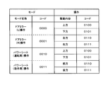
- FIG. 2 is a chart showing an example of the mode information 21b.
- the mode information 21b includes a mode name representing an operation related to the vehicle equipment to be controlled, and a code corresponding to the mode name.
- the mode name representing the operation of the door mirror 6 located on the left side when viewed from the driver's seat of the vehicle 100
- the door mirror (R) operation representing the operation of the door mirror 6 located on the right side.
- Power seat (driver's seat) operation representing the operation of the power seat 7 disposed in the driver's seat portion
- Power seat (passenger seat) operation representing the operation of the power seat 7 disposed in the passenger seat portion.
- the code corresponding to each mode name is, for example, “0000” for door mirror (L) operation.
- the mode information 21b includes driving contents by a specific operation for each mode name and a code corresponding to the driving contents.
- the driving contents are driving in the upward, downward, leftward and rightward directions.
- the power seat (driver's seat) operation and the power seat (passenger seat) operation the driving contents are the upward, downward, forward, and backward driving.
- the code corresponding to the drive content is "0100" for driving upward, common to the door mirror (L) operation, door mirror (R) operation, power seat (driver's seat) operation and power seat (passenger seat) operation, The driving to is “0101”.
- the code common to the left drive in the door mirror (L) operation and the door mirror (R) operation and the forward drive in the power seat (driver seat) operation and power seat (passenger seat) operation is “0110”. Yes.
- the code common to the rightward drive in the door mirror (L) operation and the door mirror (R) operation and the backward drive in the power seat (driver seat) operation and power seat (passenger seat) operation is “0111”. Yes.
- the mode information 21b is commonly recognized between the ECU 2 and the remote controller 3, and as will be described later, the remote controller 3 wirelessly transmits an operation signal with a code added thereto, and the ECU 2 receives the operation signal from the remote controller 3. Then, the code is read, and processing corresponding to the read code is performed.
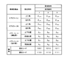
- FIG. 3 is a chart showing an example of the setting information 21c of the usage state of the vehicle equipment.
- the setting information 21c includes a vehicle equipment item, a setting item relating to a usage mode of the vehicle equipment item, a usage mode set by a passenger, and a storage number as index information.
- a storage code for storing a usage mode in association with each storage number and a read code for reading the usage mode associated with each storage number are defined. Note that the storage code and the read code are not included in the setting information 21c itself.
- Vehicle equipment included in the setting information 21c includes a door mirror (L) and a door mirror (R) corresponding to the door mirror 6, and a power seat (driver's seat) and a power seat (passenger seat) corresponding to the power seat 7.
- the setting items for the door mirror (L) and the door mirror (R) are the upper and lower angles and the left and right angles, respectively, and the setting items for the power seat (driver seat) and the power seat (passenger seat) are the upper and lower positions and the front and rear positions.
- the usage mode set by the passenger is stored in association with the storage number. As shown in FIG.
- the position ZD1 and the front / rear position XD1, the vertical position ZN1 and the front / rear position XN1 of the power seat (passenger seat) are stored.
- a storage number may be assigned to each occupant who drives the vehicle 100, and the storage number assigned to each passenger may be used.
- the usage mode stored in the setting information 21c will be described by taking the door mirror (L) and the door mirror 6 corresponding to the door mirror (R) as an example.
- An occupant who drives the vehicle 100 sits in the driver's seat and sets the vertical and horizontal angles of the mirror surface, which is the usage mode of the left and right door mirrors 6, according to his / her physique and preference.
- the vertical and horizontal angles of the mirror surface of the door mirror 6 set by the passenger are detected by the angle sensor 62a and the angle sensor 62b and input to the input / output unit 23 of the ECU 2.
- the CPU 20 when the CPU 20 receives the storage code corresponding to the storage number 1, the CPU 20 stores the vertical and horizontal angles of the mirror surface of the door mirror 6 input to the input / output unit 23 in the setting information 21c as usage modes.
- the power seat (passenger seat) is not a passenger driving the vehicle 100 but is set by the passenger to use the vehicle. The passenger seated in the driver seat and driving the vehicle 100 is separated from the passenger seated in the passenger seat.
- the usage state of the power seat (passenger seat) is stored corresponding to the storage number assigned to the passenger driving the vehicle 100.
- the usage mode of the power seat (passenger seat) may be excluded from the usage mode stored in the setting information 21c.
- the storage code is uniquely determined according to the storage number. Specifically, a storage code “1001” corresponding to storage number 1, a storage code “1010” corresponding to storage number 2, and a storage code “1011” corresponding to storage number 3 are determined. Considering the relationship in which the storage number is uniquely determined by the storage code, it can be said that the storage code, that is, index information associated with the usage mode is potentially included in the storage code as information. Similarly, the read code is uniquely determined corresponding to the storage number, and the relationship between the read code and the storage number is equivalent to the relationship between the storage code and the storage number.
- the input / output unit 23 is connected to the actuators 61a and 61b and the angle sensors 62a and 62b of the door mirrors 6, and the actuators 71a and 71b and the position sensors 72a and 72b of the power seats 7.
- the CPU 20 outputs drive signals to the actuators 61 a and 61 b of each door mirror 6 and the actuators 71 a and 71 b of each power seat 7 via the input / output unit 23. Further, the CPU 20 acquires detection signals from the angle sensors 62 a and 62 b of each door mirror 6 and the position sensors 72 a and 72 b of each power seat 7 via the input / output unit 23.
- the wireless receiving unit 24 conforms to a wireless communication standard such as Bluetooth (registered trademark), receives an operation signal transmitted from the remote controller 3, and gives the operation signal to the CPU 20. However, as long as the operation signal from the remote controller 3 can be received, the wireless reception unit 24 and the remote controller 3 may perform wireless communication based on a wireless specification uniquely determined.
- the wireless receiver 24 has a receiving antenna 24a.
- the receiving range by the receiving antenna 24a may be in the passenger compartment of the vehicle 100.
- a reception antenna extending outside the vehicle for example, by adding a reception antenna for the outside of the vehicle, is set to a certain range outside the vehicle, for example, a range of several meters from the vehicle. It should be widened.
- FIG. 4 is a block diagram showing the configuration of the remote controller 3
- FIG. 5 is a perspective view showing the appearance of the remote controller 3.
- the remote controller 3 includes an operation unit 30, a power storage unit 35, a signal processing unit 36, a transmission unit 37, and the like.
- the operation unit 30 includes a read operation unit 31, a save operation unit 32, a change operation unit 33, and a mode operation unit 34.
- the operation unit 30 receives an operation by a passenger using the vehicle 100, generates electric power, and supplies power to the power storage unit 35. At the same time, an operation is detected and output to the signal processing unit 36.
- the read operation unit 31 has read buttons 31a, 31b, and 31c corresponding to the storage numbers 1 to 3, respectively.
- the readout buttons 31a, 31b, and 31c are provided so that a part thereof protrudes from a hole provided on one surface of the casing 38 of the remote controller 3 together with other buttons.
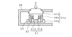
- FIG. 6 is a cross-sectional view showing the configuration of the readout button 31a.
- 6A is a cross-sectional view showing a configuration of a readout button 31a having a piezoelectric element
- FIG. 6B is a cross-sectional view showing a configuration of a readout button 31a having an induction power generation element.
- the readout buttons 31a, 31b, 31c function as operation buttons in the present invention.
- the 6A includes a switch 41a, a piezoelectric element 42a, and a holder 43a.
- the holder 43a is fixed in the housing 38, and has a recess for fixing the positions of the switch 41a and the piezoelectric element 42a.
- the piezoelectric element 42a is fitted and fixed in the concave portion of the holder 43a.
- the piezoelectric element is also called a piezoelectric element.
- the piezoelectric element 42a generates electric power when an external force is applied to the piezoelectric body disposed inside.
- a switch 41a is arranged so as to be laminated on the piezoelectric element 42a.
- the switch 41a is, for example, a press-type mechanical switch, but may be any switch that can be turned on / off by a press operation.
- a force P is applied.
- the switch 41a detects the push operation and is turned on, and the piezoelectric element 42a generates power.
- the switch 41a is connected to the signal processing unit 36, and the on / off state of the switch 41a is detected by the signal processing unit.
- the piezoelectric element 42 a is connected to the power storage unit 35, and the electric power generated by the piezoelectric element 42 a is supplied to the power storage unit 35.
- the piezoelectric element 42a functions as a power generation unit in the present invention.
- the 6B includes a switch 41a, an induction power generation element 44a, and a holder 43a.
- the holder 43a is fixed in the housing 38, and has a recess for fixing the positions of the switch 41a and the induction power generating element 44a.
- the induction power generation element 44a is fitted in the concave portion of the holder 43a, and the position in the housing 38 is fixed.
- the induction power generation element 44 a includes a magnetic circuit 51, a coil 52, and an urging member 53.
- the magnetic circuit 51 includes a magnet 51a disposed at the approximate center of the bottom of the recess provided in the holder 43a, and an iron core 51b disposed opposite to the magnet 51a with a gap.
- the urging member 53 is made of an elastic body such as rubber, and is arranged so as to surround the magnet 51a in a cylindrical shape.
- a step portion is provided on the inner surface in the axial direction of the urging member 53, and the coil 52 is fixed to the step portion.
- the iron core 51 b has a flange on the side opposite to the magnet 51 a, and the flange is in contact with one end surface of the biasing member 53 and is supported by the biasing member 53.
- the coil 52 has an annular shape, and a plurality of coils 52 are wound around the iron core 51b.
- the switch 41a is the same as in FIG.
- the induction power generation element 44a functions as a power generation unit in the present invention.
- the switch 41a When a force P is applied by the occupant pushing the read button 31a, the switch 41a detects the push operation and is turned on.
- the switch 41a is connected to the signal processing unit 36, and the on / off state of the switch 41a is detected by the signal processing unit.
- the force P due to the pushing operation is applied to the iron core 51b of the induction power generating element 44a, and the iron core 51b approaches the magnet 51a against the elastic force of the biasing member 53 that is compressed in the axial direction.
- the magnetic flux in the iron core 51b changes and the magnetic flux density increases, and an induced electromotive force is generated in the coil 52 accordingly.
- the coil 52 of the induction power generation element 44 a is connected to the power storage unit 35, and power generated by the coil 52 is supplied to the power storage unit 35.
- the force P is removed, and the iron core 51b is separated from the magnet 51a and returned to the original position by the restoring force of the urging member 53.
- a thin elastic sheet may be provided as a buffer material between the magnet 51a and the iron core 51b.
- the read buttons 31b and 31c have the same configuration as the read button 31a.
- the push operation is detected by the switch of each button, and the switch is turned on. Is detected by the signal processing unit.
- electric power is generated and applied to the power storage unit 35 by applying force generated by the occupant's pushing operation to the piezoelectric element or the induction power generation element included in each button.
- the save operation unit 32 has save buttons 32a, 32b, and 32c corresponding to the save numbers 1 to 3, respectively.
- the save buttons 32a, 32b, and 32c are provided so that a part of the save buttons 32a, 32b, and 32c protrudes from a hole provided on one surface of the casing 38 of the remote controller 3 together with other buttons.
- the save buttons 32a, 32b, and 32c are configured similarly to the read button 31a shown in FIG.
- buttons 32a, 32b, and 32c function as the second operation button in the present invention.
- the change operation unit 33 has change buttons 33a, 33b, 33c, and 33d corresponding to the driving contents for changing the usage mode of the vehicle equipment.
- the change button 33a corresponds to the upward drive
- the change button 33b corresponds to the downward drive
- the change button 33c corresponds to the left or forward drive
- the change button 33d corresponds to the right or backward drive.
- the change buttons 33a, 33b, 33c, and 33d are provided so that a part of the change buttons 33a, 33b, 33c, and 33d protrudes from a hole provided on one surface of the casing 38 of the remote controller 3.
- the change buttons 33a, 33b, 33c, and 33d are configured similarly to the read button 31a shown in FIG.
- the change buttons 33a, 33b, 33c, and 33d When the occupant pushes the change buttons 33a, 33b, 33c, and 33d, the push operation is detected by the switch of each button, and the ON state of the switch is detected by the signal processing unit. In addition, electric power is generated and applied to the power storage unit 35 by applying force generated by the occupant's pushing operation to the piezoelectric element or the induction power generation element included in each button.
- the change buttons 33a, 33b, 33c, and 33d function as the third operation button in the present invention.
- the mode operation unit 34 has mode buttons 34a, 34b, 34c, and 34d corresponding to each vehicle equipment.
- the mode button 34a corresponds to the door mirror (L)
- the mode button 34b corresponds to the door mirror (R)
- the mode button 34c corresponds to the power seat (driver's seat)
- the mode button 34d corresponds to the power seat (passenger seat).
- the mode buttons 34a, 34b, 34c, and 34d are provided so that a part of the mode buttons 34a, 34b, 34c, and 34d protrudes from a hole provided on one surface of the casing 38 of the remote controller 3 together with the other buttons.
- the mode buttons 34a, 34b, 34c, and 34d are configured in the same manner as the readout button 31a shown in FIG.
- the push operation is detected by the switch of each button, and the ON state of the switch is detected by the signal processing unit.
- electric power is generated and applied to the power storage unit 35 by applying force generated by the occupant's pushing operation to the piezoelectric element or the induction power generation element included in each button.
- the mode buttons 34a, 34b, 34c, 34d function as the fourth operation button in the present invention.
- the power storage unit 35 includes a rectifier circuit using a diode or the like and a smoothing circuit using a capacitor or the like, and rectifies and smoothes the electric power supplied from each operation button of the operation unit 30 and accumulates it.
- the power storage unit 35 supplies the stored power to the signal processing unit 36 and the transmission unit 37.
- a constant voltage circuit using a Zener diode or the like may be provided in the power storage unit 35 to supply power to the signal processing unit 36 and the transmission unit 37 with a constant voltage.
- the signal processing unit 36 detects which switch of each button of the operation unit 30 is in the on state, and outputs a code corresponding to the button in the on state to the transmission unit 37.
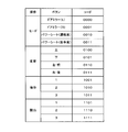
- FIG. 7 is a chart showing an example of codes corresponding to the buttons of the operation unit 30.
- the mode button 34 a corresponds to the door mirror (L) operation mode
- the signal processing unit 36 outputs the code “0000” to the transmission unit 37 when the mode button 34 a is pressed.
- the code used in the remote controller 3 shown in FIG. 7 is the same as the code used in the ECU 2 shown in FIGS.
- the signal processing unit 36 may be a ROM having a code stored therein, a microcomputer having a CPU that detects the ON state of each button, reads out the corresponding code from the ROM, and outputs it, or is an analog circuit using discrete components. May be.
- the analog circuit uses a circuit that connects a DC power source provided from the switch, resistor, and power storage unit 35 of each button in series and outputs a voltage generated at both ends of the resistor, according to a code corresponding to each button.
- a code generation circuit for generating high / low signals at the four output terminals is provided, and the four output terminals of the code generation circuit of each button are combined corresponding to the bit positions, and are used as four parallel output terminals to the transmission unit 37. That's fine.
- the configuration of the analog circuit is not limited to that described above.
- the transmission unit 37 operates based on the power supplied from the power storage unit 35 and generates an operation signal to which a code input from the signal processing unit 36 is added.
- the operation signal may include only the code from the signal processing unit 36, or may further include a signal for synchronization and identification, and a signal added to comply with the wireless communication standard.
- the transmission unit 37 generates a carrier wave by an oscillation circuit (not shown), modulates the carrier wave with an operation signal, and transmits the modulated carrier wave.
- the operation signal may be encoded by, for example, Manchester encoding.
- a transmission signal output from the transmission unit 37 is wirelessly transmitted via the antenna 39.
- the operation unit 30 of the remote controller 3 is operated by a passenger boarding the vehicle 100.
- a mode button 34a corresponding to, for example, the door mirror (L) among the buttons of the mode operation unit 34 is pressed
- power is supplied to the power storage unit 35, and the switch of the mode button 34a is turned on.
- the signal processing unit 36 receives power supply from the power storage unit 35, detects the on state of the switch included in the mode button 34 a, and outputs a corresponding code (in this case, “0000”) to the transmission unit 37.
- the transmission unit 37 generates a carrier wave based on the electric power supplied from the power storage unit 35, generates an operation signal to which the code input from the signal processing unit 36 is added, modulates the carrier wave with the operation signal, and converts the ECU 2 Send to.
- the buttons of the change operation unit 33, the save operation unit 32, and the read operation unit 31 are operated by the power storage unit 35, the signal processing unit 36, and the transmission unit 37, and codes corresponding to the pressed buttons are added.
- the operation signal thus transmitted is transmitted from the remote controller 3.
- FIG. 8 is a flowchart showing a procedure of operation processing in the ECU 2.
- the CPU 20 of the ECU 2 receives the operation signal transmitted from the remote controller 3 by the wireless reception unit 24 (step S1).
- the CPU 20 determines whether or not the received operation signal is a signal related to reading based on a code included in the operation signal (step S2).
- the operation signal is a signal related to reading (S2: YES)
- the usage mode of the storage number corresponding to the code included in the received operation signal is read from the setting information 21c stored in the ROM 21 (step S3). Based on the usage mode, the door mirror 6 and the power seat 7 are instructed to drive (step S4).
- the CPU 20 outputs drive signals for driving the door mirror (L) and the door mirror (R) corresponding to the door mirror 6, and reads the vertical and horizontal angles of each mirror detected by the angle sensors 62a and 62b. Continue to drive until the desired usage. Further, the CPU 20 outputs drive signals for driving the power seat (driver's seat) and the power seat (passenger seat) corresponding to the power seat 7, and the vertical position and front / rear position of each seat detected by the position sensors 72a and 72b are determined. The driving is continued until the read usage state is obtained.
- the CPU 20 determines whether or not the received operation signal is a signal related to storage based on a code included in the operation signal (step S5).
- the operation signal is a signal related to storage (S5: YES)
- each usage mode of the vehicle equipment at the current time point is acquired based on the detection signals of the angle sensors 62a and 62b and the position sensors 72a and 72b.
- the acquired usage state is stored in the storage unit 21 in association with the storage number corresponding to the code included in the stored information in the setting information 21c (step S6).
- the CPU 20 ends the process.
- the CPU 20 determines whether or not the received operation signal is a signal related to the change, based on a code included in the operation signal (step S7).
- the CPU 20 commands the drive corresponding to the code included in the operation signal. For example, when the code included in the operation signal is “0100”, the CPU 20 is driven upward of any one of the door mirror (L), the door mirror (R), the power seat (driver's seat), or the power seat (passenger seat). (Step S8), and after the command, the process is terminated.
- the operation signal related to the mode before the operation signal related to the change Is received by the CPU 20, and the vehicle equipment must be selected and the vehicle equipment to be driven must be specified. If no vehicle equipment has been selected and the vehicle equipment to be driven cannot be specified, and a signal related to the change is received, the CPU 20 ends the processing as an error.
- the CPU 20 determines whether or not the received operation signal is a signal related to the mode based on the code included in the operation signal (step S9).
- the CPU 20 selects the vehicle equipment corresponding to the code included in the operation signal (step S10), and should be driven when the change signal is received next. Identify vehicle equipment. Specifically, when the code included in the operation signal is “0010”, the power seat (driver's seat) is selected, and the code “0010” corresponding to the selected vehicle equipment is temporarily stored in the RAM 22. The vehicle equipment to be driven is specified.
- the drive command by the CPU 20 in the above-described step S8 is performed on the corresponding vehicle equipment with reference to the code indicating the specific vehicle equipment temporarily stored in the RAM 22.
- the CPU 20 temporarily stores the code corresponding to the vehicle equipment in the RAM 22 and then ends the process.
- the CPU 20 determines that the received operation signal does not correspond to any of the signals related to reading, saving, changing and mode, and operating the occupant again.
- Voice guidance for outputting a message such as "Please operate again" from a speaker (not shown) is performed (step S11), and the process is terminated.
- the door mirror (L), the door mirror (R), and the power seat (driver's seat) are sequentially selected by pressing the buttons on the mode operation unit 34 of the remote controller 3. Then, by pressing the button of the change operation unit 33, the usage mode of the currently selected on-vehicle equipment is changed according to its own physique and preference.
- the usage mode of the power seat (passenger seat) is changed by the passenger seated in the passenger seat.
- the button of the storage operation unit 32 is pushed by the occupant, and the usage mode of each vehicle equipment is stored in the storage unit in association with the storage number corresponding to the pressed button.
- the information is stored in the setting information 21c.
- a storage number is assigned to each occupant seated in the driver's seat, and the usage mode of each vehicle equipment is stored in the setting information 21c corresponding to the storage number.
- the passenger presses the button on the reading operation unit 31 to read out the usage mode of each vehicle equipment stored when the user sat in the driver's seat from the setting information 21c.
- the CPU 20 automatically sets the vehicle equipment according to the read usage mode.
- the ECU 2 stores the vehicle equipment that can take different usage modes, for example, the usage mode of the door mirror 6, the power seat 7, etc., in association with the storage number as index information. Control is performed to change the usage mode of the vehicle equipment based on the usage mode.
- the remote controller 3 accepts an operation by the occupant and transmits an operation signal related to the operation to the ECU 2 by radio.
- the remote controller 3 accepts an operation associated with the storage number via the operation unit 30.
- a code corresponding to the storage number associated with the operation received by the operation unit 30 is added using the generated power by receiving power from the operation unit 30 to generate power using a power generation element such as the piezoelectric element 42a and the induction power generation element 44a.
- the operation signal is transmitted by the transmission unit 37.
- the ECU 2 stores the usage state of the vehicle equipment in the ROM 21 in association with the storage number, and receives the operation signal by the wireless reception unit 24.
- the CPU 20 reads the usage mode corresponding to the storage number from the setting information 21c of the ROM 21 based on the code added to the operation signal received by the wireless reception unit 24, and changes the usage mode of the vehicle equipment to the read usage mode. Control. Thereby, the usage mode of the vehicle equipment can be set by wirelessly transmitting the operation signal using the generated power.
- the operation unit 30 since the operation unit 30 has the read buttons 31a, 31b, 31c for each storage number as index information, by operating the read buttons 31a, 31b, 31c provided on the remote controller 3,
- the usage mode of the vehicle equipment associated with a plurality of storage numbers can be set. For example, a separate storage number is assigned to each of a plurality of occupants, and the usage mode of the vehicle equipment can be set for each occupant with one remote controller 3.
- the operation unit 30 has the save buttons 32a, 32b, and 32c for each save number as index information, and the use mode of the vehicle equipment is stored in the ROM 21 by the save buttons 32a, 32b, and 32c.
- the operation to be accepted is accepted.
- the transmission unit 37 transmits an operation signal to which a code designating that the usage mode corresponding to the storage number related to the storage button for which the operation is accepted is stored in the ROM 21 is added.
- the CPU 20 stores the usage mode of the vehicle equipment in the ROM 21 based on the code added to the operation signal received by the wireless reception unit 24.
- the save buttons 32a, 32b, and 32c for each save number provided on the remote controller 3 the usage mode of the vehicle equipment can be stored in the ROM 21 in association with a plurality of save numbers.
- the operation unit 30 has the change buttons 33a, 33b, 33c, and 33d, and accepts an operation for changing the usage state of the vehicle equipment by the change buttons 33a, 33b, 33c, and 33d.
- the transmission unit 37 transmits an operation signal to which a code specifying that the usage mode of the vehicle equipment related to the change button for which the operation has been received is changed is added.
- the CPU 20 performs control to change the usage mode of the vehicle equipment based on the code added to the operation signal received by the wireless reception unit 24. Thereby, the usage mode of the vehicle equipment can be changed by operating the change buttons 33a, 33b, 33c and 33d provided on the remote controller 3.
- the operation unit 30 has the mode button 34a
- An operation for selecting (specifying) the vehicle equipment is accepted by 34b, 34c, and 34d.
- the transmission unit 37 transmits an operation signal to which a code for identifying the vehicle equipment related to the mode button for which the operation has been accepted is added. Based on the code added to the operation signal received by the wireless reception unit 24, the CPU 20 specifies and controls one vehicle equipment item from the plurality of vehicle equipment items.
- the mode buttons 34a, 34b, 34c, and 34d provided on the remote controller 3 it is possible to perform control for specifying one vehicle equipment from a plurality of vehicle equipment and changing the use mode. .
- the usage mode of the vehicle equipment can be changed by operating the remote controller 3, it is not necessary to provide an operation switch for changing the usage mode of the vehicle equipment in the vehicle 100, and the wire harness for the operation switch is saved.
- the remote controller 3 has the piezoelectric element 42a as the power generation unit for each button of the operation unit 30, and the piezoelectric element 42a generates power by receiving the force by the operation on the operation unit 30. An operation signal is transmitted from the remote controller 3 using the generated power.
- the remote controller 3 has the induction power generation element 44 a including the magnetic circuit 51 and the coil 52 as the power generation unit for each button of the operation unit 30, and the magnetic flux of the magnetic circuit 51 is operated by operating the operation unit 30. Changes, and an electromotive force is induced in the coil 52 in accordance with the change in the magnetic flux of the magnetic circuit 51. Therefore, an operation signal is transmitted from the remote controller 3 using the electromotive force induced in the coil 52.
- the door mirror 6 is provided with the angle sensors 62a and 62b, and the power seat 7 is provided with the position sensors 72a and 72b.
- the angle sensor and the position sensor may not be provided.
- the one-side limit position of the driving range is determined as the home position, and the vertical and horizontal angles of the door mirror are determined by the driving amount from the home position.
- the driving amount from the home position may be stored in the setting information 21c as a usage mode of the door mirror 6, and the CPU 20 reads the driving amount from the setting information 21c, and based on the read driving amount, Lower and left and right corners can be set. The same applies to the power seat 7.
- the switch 41a is provided for each button of the operation unit 30.
- a resistor is connected to the piezoelectric element 42a, and a voltage change between both ends of the resistor is detected.
- An operation detector that detects that the operation has been performed may be substituted for the switch 41a, and detection information of the operation detector may be input to the signal processing unit 36.
- the signal processing unit 36 may output a code corresponding to the operation based on the detection information of the operation detector, as in the above-described embodiment.
- a power generation element such as a piezoelectric element or an induction power generation element is provided for each button of the operation unit 30.
- a plurality of adjacent buttons are grouped, and a power generation element is provided for each group. May be.
- the remote control 3 includes a power generation element such as a piezoelectric element or an induction power generation element, and operates by generating electric power by the remote control 3 itself by an occupant's operation.
- a button battery may be incorporated.
- the switch of the button of the operation unit 30 is turned on by a pressing operation, power is temporarily supplied from the built-in battery to the power storage unit 35, and the rise time of the power accumulated in the power storage unit 35 is set. By shortening, the time delay until the operation signal is transmitted is reduced, and there is a possibility that the feeling of operation by the occupant can be improved.
- the remote controller 3 may include a solar battery as an auxiliary power source instead of a small battery.
- Vehicle equipment control system ECU (control device) 20 CPU (control unit) 21 ROM (storage unit) 24 Wireless receiver (receiver) 3 Remote control (transmitter) 30 Operation part 31a, 31b, 31c Reading button (operation button) 32a, 32b, 32c Save button (second operation button) 33a, 33b, 33c, 33d Change button (third operation button) 34a, 34b, 34c, 34d Mode button (fourth operation button) 37 Transmitter 42a Piezoelectric Element (Power Generator) 44a Induction power generation element (power generation section) 51 Magnetic circuit 52 Coil
Landscapes
- Engineering & Computer Science (AREA)
- Mechanical Engineering (AREA)
- Selective Calling Equipment (AREA)
Abstract
発電した電力を用いて操作信号を無線で送信することで車輌装備品の使用態様を設定することができ、更にはワイヤーハーネスを省線化することができる車輌装備品制御システムを提供する。ECU2は車輌装備品、例えばドアミラー6、パワーシート7等の使用態様を保存番号に対応付けて記憶し、使用態様を変更する制御を行う。リモコン3は、保存番号に対応付けられた操作を受け付けるとともに、操作により力を受けて発電素子で発電し、保存番号に対応するコードを付加した操作信号を送信する。ECU2は、無線受信部24により受信した操作信号に付加されたコードに基づいて、保存番号に対応する使用態様をROM21の設定情報21cから読み出し、車輌装備品の使用態様を変更する制御を行う。
Description
本発明は、車輌装備品の使用態様を制御する車輌装備品制御システムに関する。
従来、ドアミラー、シート等の車輌装備品は、乗員が、体格、好み等に合わせて個別に角度、位置等の使用態様を設定している。同一の乗員は、毎回、車輌装備品をほぼ同一の使用態様にする。そこで、乗員が乗車する都度、車輌装備品の使用態様を設定する手間を省くために、使用態様の設定を自動化する車輌装備品制御システムが案出されるに至っている。
例えば、特許文献1には、シート等の位置を変更するための駆動装置と、乗員毎に携帯されるキーレスリモコンと、シート等の位置情報を記憶する記憶部を有し、該キーレスリモコンの開錠操作に基づき、該記憶部に記憶された位置情報を呼び出して駆動装置を動作せしめ、シート等を記憶された位置に自動で設定する制御を行う制御装置とを備える従来の車輌装備品制御システムが記載されている。
この従来の車輌装備品制御システムは、キーレスリモコン毎に固有のリモコンIDが付けられており、該リモコンIDに対応付けてシート等の位置情報を記憶部に記憶する。車輌を利用する複数の乗員は、夫々別のリモコンIDが付されたキーレスリモコンを携帯する。制御装置は、リモコンIDを取得すると、該リモコンIDに対応付けて記憶部に記憶している位置情報を読み出し、シート等の位置を自動設定する制御を行う。
しかしながら、特許文献1に記載の従来の車輌装備品制御システムでは、複数の乗員が交代で車輌を運転するような場合には、乗員各自が別個のキーレスリモコンを所持していなければならず、所持し忘れた場合にはシート等の車輌装備品の自動設定を利用できないという問題点があった。
通常、キーレスリモコンは電池で動作するため、電池が切れると車輌装備品の自動設定を利用できない。また、1台の車輌を利用する乗員が多人数である場合には、キーレスリモコンを多数用意しなければならなくなるとともに、電池交換の手間も増える。
また、従来の車輌装備品制御システムでは、車輌装備品の使用態様の調整及び変更を行うための操作スイッチが設けられており、該操作スイッチと制御装置とを電気的に接続するためのワイヤーハーネスが必要となり、車輌内にワイヤーハーネスを配索するための経路及び空間を確保しなければならないという制約が生じるという問題点があった。
本発明は斯かる事情に鑑みてなされたものであり、発電した電力を用いて操作信号を無線で送信することで車輌装備品の使用態様を設定することができ、更にはワイヤーハーネスを省線化することができる車輌装備品制御システムを提供することを目的とする。
本発明に係る車輌装備品制御システムは、異なる使用態様をとり得る車輌装備品の使用態様を索引情報に対応付けて記憶し、記憶している使用態様に基づいて前記車輌装備品の使用態様を変更する制御を行う制御装置と、操作を受け付け、該操作に係る操作信号を無線により前記制御装置へ送信する送信機とを備える車輌装備品制御システムにおいて、前記送信機は、前記索引情報に対応付けられた操作を受け付ける操作部、該操作部に対する操作により力を受けて発電する発電部、及び該発電部により発電した電力を用い、前記操作部により受け付けた操作に係る索引情報に対応する情報を付加した操作信号を送信する送信部を有し、前記制御装置は、前記索引情報に対応付けて前記車輌装備品の使用態様を記憶する記憶部、前記操作信号を受信する受信部、及び該受信部により受信した操作信号に付加された情報に基づく索引情報に対応する使用態様を前記記憶部から読み出し、読み出した使用態様に前記車輌装備品の使用態様を変更する制御を行う制御部を有することを特徴とする。
本発明にあっては、制御装置が、異なる使用態様をとり得る車輌装備品の使用態様を索引情報に対応付けて記憶し、記憶している使用態様に基づいて車輌装備品の使用態様を変更する制御を行う。送信機は、操作を受け付け、該操作に係る操作信号を無線により制御装置へ送信する。送信機は、操作部により索引情報に対応付けられた操作を受け付け、操作部に対する操作により力を受けて発電部により発電し、発電した電力を用い、操作部により受け付けた操作に係る索引情報に対応する情報を付加した操作信号を送信部により送信する。制御装置は、索引情報に対応付けて車輌装備品の使用態様を記憶部に記憶し、受信部により操作信号を受信する。制御部は、受信部により受信した操作信号に付加された情報に基づく索引情報に対応する使用態様を記憶部から読み出し、読み出した使用態様に車輌装備品の使用態様を変更する制御を行う。これにより、発電した電力を用いて操作信号を無線で送信することで車輌装備品の使用態様を設定することができる。
本発明に係る車輌装備品制御システムは、前記操作部が、前記索引情報毎に操作釦を有することを特徴とする。
本発明にあっては、操作部が索引情報毎に操作釦を有するので、送信機に設けられた索引情報毎の操作釦を操作することで、複数の索引情報に対応付けられた車輌装備品の使用態様を設定することができる。例えば、複数の乗員毎に別個の索引情報を割り当て、1台の送信機で乗員毎に車輌装備品の使用態様を設定することができる。
本発明に係る車輌装備品制御システムは、前記操作部が、前記索引情報毎に、前記記憶部に前記車輌装備品の使用態様を記憶させる操作を受け付ける第2操作釦を有し、前記送信部は、操作が受け付けられた第2操作釦に係る索引情報に対応する使用態様を前記記憶部に記憶させることを指定する情報を付加した操作信号を送信し、前記制御部は、前記受信部により受信した操作信号に付加された情報に基づき、車輌装備品の使用態様を前記記憶部に記憶させるようにしてあることを特徴とする。
本発明にあっては、操作部が索引情報毎に第2操作釦を有し、該第2操作釦により、記憶部に車輌装備品の使用態様を記憶させる操作を受け付ける。送信部は、操作が受け付けられた第2操作釦に係る索引情報に対応する使用態様を記憶部に記憶させることを指定する情報を付加した操作信号を送信する。制御部は、受信部により受信した操作信号に付加された情報に基づき、車輌装備品の使用態様を記憶部に記憶させる。これにより、送信機に設けられた索引情報毎の第2操作釦を操作することで、複数の索引情報に対応付けて車輌装備品の使用態様を記憶部に記憶させることができる。
本発明に係る車輌装備品制御システムは、前記操作部が、前記車輌装備品の使用態様を変更する操作を受け付ける第3操作釦を有し、前記送信部は、操作が受け付けられた第3操作釦に係る前記車輌装備品の使用態様を変更することを指定する情報を付加した操作信号を送信し、前記制御部は、前記受信部により受信した操作信号に付加された情報に基づき、前記車輌装備品の使用態様を変更する制御を行うようにしてあることを特徴とする。
本発明にあっては、操作部が第3操作釦を有し、該第3操作釦により、車輌装備品の使用態様を変更する操作を受け付ける。送信部は、操作が受け付けられた第3操作釦に係る車輌装備品の使用態様を変更することを指定する情報を付加した操作信号を送信する。制御部は、受信部により受信した操作信号に付加された情報に基づき、車輌装備品の使用態様を変更する制御を行う。これにより、送信機に設けられた第3操作釦を操作することで、車輌装備品の使用態様を変更することができる。また、車輌装備品の使用態様の変更を送信機の操作で行えるので、車輌に車輌装備品の使用態様を変更するための操作スイッチを設ける必要が無く、操作スイッチ用のワイヤーハーネスを省線化することができる。
本発明に係る車輌装備品制御システムは、前記車輌装備品が複数であり、前記操作部は、前記車輌装備品を特定する操作を受け付ける第4操作釦を有し、前記送信部は、操作が受け付けられた第4操作釦に係る前記車輌装備品を特定する情報を付加した操作信号を送信し、前記制御部は、前記受信部により受信した操作信号に付加された情報に基づき、複数の前記車輌装備品から一の車輌装備品を特定して制御を行うようにしてあることを特徴とする。
本発明にあっては、車輌装備品が複数であり、操作部が第4操作釦により車輌装備品を特定する操作を受け付ける。送信部は、操作が受け付けられた第4操作釦に係る車輌装備品を特定する情報を付加した操作信号を送信する。制御部は、受信部により受信した操作信号に付加された情報に基づき、複数の前記車輌装備品から一の車輌装備品を特定して制御を行う。これにより、送信機に設けられた第4操作釦を操作することで、複数の車輌装備品から一の車輌装備品を特定して使用態様を変更する制御を行うことができる。
本発明に係る車輌装備品制御システムは、前記発電部が、前記操作部に対する操作により力を受けて発電する圧電素子を有することを特徴とする。
本発明にあっては、発電部は圧電素子を有し、操作部に対する操作により力を受けて該圧電素子が発電するので、発電された電力を用いて送信機から操作信号を送信される。
本発明に係る車輌装備品制御システムは、前記発電部が、前記操作部に対する操作により磁束が変化する磁気回路、及び該磁気回路の磁束の変化に応じて起電力が誘導されるコイルを有することを特徴とする。
本発明にあっては、発電部が磁気回路とコイルを有し、操作部に対する操作により磁気回路の磁束が変化し、該磁気回路の磁束の変化に応じてコイルに起電力が誘導されるので、コイルに誘導された起電力を用いて送信機から操作信号を送信される。
本発明によれば、制御装置は、異なる使用態様をとり得る車輌装備品の使用態様を索引情報に対応付けて記憶し、記憶している使用態様に基づいて車輌装備品の使用態様を変更する制御を行う。送信機は、操作を受け付け、該操作に係る操作信号を無線により制御装置へ送信する。送信機は、操作部により索引情報に対応付けられた操作を受け付け、操作部に対する操作により力を受けて発電部により発電し、発電した電力を用い、操作部により受け付けた操作に係る索引情報に対応する情報を付加した操作信号を送信部により送信する。制御装置は、索引情報に対応付けて車輌装備品の使用態様を記憶部に記憶し、受信部により操作信号を受信する。制御部は、受信部により受信した操作信号に付加された情報に基づく索引情報に対応する使用態様を記憶部から読み出し、読み出した使用態様に車輌装備品の使用態様を変更する制御を行う。このため、発電した電力を用いて操作信号を無線で送信することで車輌装備品の使用態様を設定することができる。
以下、本発明をその実施の形態を示す図面に基づき具体的に説明する。図1は本発明の実施の形態に係る車輌装備品制御システム1の構成を示すブロック図である。車輌装備品制御システム1は、車輌100に搭載されたECU(Electronic Control Unit)2及びリモートコントローラ(以下、リモコンと表記する。)3を備え、乗員による操作をリモコン3で受け付け、ECU2により車輌装備品の使用態様に係る選択(特定)、変更、保存及び読出等の制御を行う。図1には、乗員が自身の体格、好み等に合わせて個別に異なる使用態様を設定する車輌装備品の例として、車輌100の左右に配置されているドアミラー6,6、運転席及び助手席部分に配置されているパワーアシストシート(以下、パワーシートと表記する。)7,7を示す。図1に示す以外にも、乗員が個別に使用態様を設定する車輌装備品として、例えば車輌100後方を視認するためのルームミラー、操向用のステアリングハンドル、ヘッドレスト、カーナビゲーション装置等が挙げられる。本実施の形態では、ドアミラー6及びパワーシート7を車載装備品の例として説明するが、上述のルームミラー等についても同様に本発明を適用する車載装備品とすることができる。尚、ECU2は本発明における制御装置として機能し、リモコン3は本発明における送信機として機能する。
まず、車輌装備品について説明する。ドアミラー6は、鏡面(図示略)が向く方向の上下角を可変とするアクチュエータ61a、左右角を可変とするアクチュエータ61b、上下角を検出する角度センサ62a、及び左右角を検出する角度センサ62bを備える。アクチュエータ61a及び61bは例えば回転モータであり、ECU2に接続され、ECU2からの駆動信号に基づいて動作する。アクチェータ61aはドアミラー6の鏡面が向く方向を上下方向に駆動し、アクチュエータ61bはドアミラー6の鏡面が向く方向を左右方向に駆動する。
角度センサ62a及び62bは例えばポテンショメータであり、ECU2に接続され、抵抗値の変化により検出対象の角度を検出してECU2へ出力する。角度センサ62aはドアミラー6の鏡面の上下角を、角度センサ62bはドアミラー6の鏡面の左右角を検出する。
パワーシート7は、シートを上下方向に昇降駆動するアクチュエータ71a、車輌100の前後方向に摺動駆動するアクチュエータ71b、上下方向の位置を検出する位置センサ72a、及び前後方向の位置を検出する位置センサ72bを備える。アクチュエータ71aは例えばシートを上下に昇降させるリフトアップ機構及び該機構に駆動力を与える回転モータ(図示略)で構成されており、ECU2からの駆動信号に基づいて動作する。アクチュエータ71bは例えばシートを前後に摺動させるスライド機構及び該機構に駆動力を与える回転モータで構成されており、ECU2からの駆動信号に基づいて動作する。
位置センサ72a及び72bは例えばポテンショメータであり、ECU2に接続され、抵抗値の変化により検出対象の位置を検出してECU2へ出力する。位置センサ72aは、シートを上下に昇降するリフトアップ機構を駆動する回転モータの回転角を検出することで、シートの上下位置を検出する。シート昇降の下限及び上限間で回転モータの出力軸が1回転以上回転する場合には、減速ギアを位置センサ72aに取り付けることで位置センサ72a上は1回転に相当するようにする。位置センサ72bは、シートを前後に摺動するスライド機構を駆動する回転モータの回転角を検出することで、シートの前後位置を検出する。シート摺動の前側限界及び後側限界間で回転モータの出力軸が1回転以上回転する場合には、減速ギアを位置センサ72bに取り付けることで位置センサ72b上は1回転に相当するようにする。
次に車輌装備品制御システム1におけるECU2について説明する。ECU2は、CPU(Central Processing Unit)20と、フラッシュメモリ、EPROM(Erasable Programmable Read Only Memory)、EEPROM(Electrically EPROM)等の不揮発性メモリを利用したROM21と、DRAM(Dynamic Random Access Memory)、SRAM(Static Random Access Memory)等のメモリを利用したRAM22と、車輌装備品との間でセンサ信号及び駆動信号を入出力する入出力部23と、リモコン3が送信する操作信号を無線により受信する無線受信部24とを備える。CPU20、ROM21、RAM22、入出力部23及び無線受信部24はバスMで接続されており、相互に信号の入出力を行うことができる。CPU20、ROM21、RAM22、入出力部23、無線受信部24及びバスMでマイクロコンピュータを構成してもよい。尚、CPU20は本発明における制御部として機能し、ROM21は本発明における記憶部として機能し、無線受信部24は本発明における受信部として機能する。
ROM21には、CPU20が読み出して実行する制御プログラム21a、リモコン3による操作に係るモード情報21b、及び乗員によって設定された車輌装備品の使用態様を索引情報に対応付けて保存する設定情報21cが記憶されている。設定情報21cは、乗員の操作によって情報の保存が随時可能となるように、書き込みが可能で不揮発性の記憶領域に保存されるものとする。RAM22には、CPU20の処理の過程で発生する情報が一時的に記憶される。
図2はモード情報21bの例を示す図表である。モード情報21bは、制御の対象とする車輌装備品に係る操作を表わすモード名称、該モード名称に対応するコードを含む。図2に示す例では、モード名称として、車輌100の運転席から見て左側に位置するドアミラー6の操作を表わすドアミラー(L)操作、右側に位置するドアミラー6の操作を表わすドアミラー(R)操作、運転席部分に配置されているパワーシート7の操作を表わすパワーシート(運転席)操作、助手席部分に配置されているパワーシート7の操作を表わすパワーシート(助手席)操作が挙げられている。各モード名称に対応するコードは、例えばドアミラー(L)操作につき「0000」などとしている。
さらにモード情報21bには、各モード名称に対する具体的な操作による駆動内容、及び該駆動内容に対応するコードを含む。ドアミラー(L)操作及びドアミラー(R)操作について、駆動内容は上方、下方、左方、及び右方への各駆動である。また、パワーシート(運転席)操作及びパワーシート(助手席)操作について、駆動内容は上方、下方、前方、及び後方への各駆動である。駆動内容に対応するコードは、ドアミラー(L)操作、ドアミラー(R)操作、パワーシート(運転席)操作及びパワーシート(助手席)操作に共通して、上方への駆動を「0100」、下方への駆動を「0101」としている。また、ドアミラー(L)操作及びドアミラー(R)操作における左方への駆動、並びにパワーシート(運転席)操作及びパワーシート(助手席)操作における前方への駆動に共通するコードを「0110」としている。また、ドアミラー(L)操作及びドアミラー(R)操作における右方への駆動、並びにパワーシート(運転席)操作及びパワーシート(助手席)操作における後方への駆動に共通するコードを「0111」としている。
モード情報21bはECU2とリモコン3との間で共通して認識されており、後述するようにリモコン3はコードを付加した操作信号を無線で送信し、ECU2は、リモコン3からの操作信号を受信してコードを読出し、読出したコードに対応する処理を行う。
図3は車輌装備品の使用態様の設定情報21cの例を示す図表である。設定情報21cは、車輌装備品、該車輌装備品の使用態様に係る設定項目、及び乗員により設定された使用態様、索引情報としての保存番号が含まれている。また、各保存番号に対応付けて使用態様を保存する保存コード、及び各保存番号に対応付けられた使用態様を読み出す読出コードが定められている。尚、保存コード及び読出コードは設定情報21c自体に含まれるものではない。
設定情報21cに含まれる車輌装備品は、ドアミラー6に対応するドアミラー(L)及びドアミラー(R)、並びにパワーシート7に対応するパワーシート(運転席)及びパワーシート(助手席)である。ドアミラー(L)及びドアミラー(R)夫々の設定項目は上下角、左右角であり、パワーシート(運転席)及びパワーシート(助手席)夫々の設定項目は上下位置、前後位置である。乗員により設定された使用態様は保存番号に対応付けて保存される。図3に示すように、例えば保存番号1に対応して、ドアミラー(L)の上下角θLV1 及び左右角θLH1 、ドアミラー(R)の上下角θRV1 及び左右角θRH1 、パワーシート(運転席)の上下位置ZD1 及び前後位置XD1 、及びパワーシート(助手席)の上下位置ZN1 及び前後位置XN1が保存される。保存番号2、保存番号3についても同様である。尚、保存番号の利用に関しては、車輌100を運転する乗員夫々に保存番号を割り当てておき、乗員毎に自身に割り当てられた保存番号を利用するようにすればよい。
設定情報21cに保存する使用態様について、ドアミラー(L)及びドアミラー(R)に対応するドアミラー6を例にして説明する。車輌100を運転する乗員は、運転席に着座して自身の体格や好みに合わせて左右のドアミラー6の使用態様である鏡面の上下角及び左右角を設定する。乗員によって設定されたドアミラー6の鏡面の上下角及び左右角は、角度センサ62a及び角度センサ62bによって検出され、ECU2の入出力部23に入力される。CPU20は、例えば保存番号1に対応する保存コードを受け付けると、入出力部23に入力されているドアミラー6の鏡面の上下角及び左右角を使用態様として設定情報21cに保存する。パワーシート(運転席)についても同様である。パワーシート(助手席)は、車輌100を運転する乗員ではなく、同乗者が使用態様を設定するものであるが、運転席に着座して車輌100を運転する乗員と、助手席に着座する別の乗員とが毎回概ね同じとなる場合を考慮して、車輌100を運転する乗員に割り当てられた保存番号に対応してパワーシート(助手席)の使用態様を保存する。尚、パワーシート(助手席)の使用態様は、設定情報21cに保存する使用態様から除外しても良い。
保存コードは保存番号に対応して一意に定められている。具体的には保存番号1に対応して保存コード「1001」、保存番号2に対応して保存コード「1010」、保存番号3に対応して保存コード「1011」のように定める。保存コードにより保存番号が一意に決まる関係を考慮すると、保存番号、即ち使用態様が対応付けられる索引情報が保存コードに潜在的に情報として含まれているといえる。同様に、読出コードは保存番号に対応して一意に定められており、読出コードと保存番号との関係は保存コードと保存番号との関係と同等である。
入出力部23には、各ドアミラー6のアクチュエータ61a及び61b、並びに角度センサ62a及び62bが、更に各パワーシート7のアクチュエータ71a及び71b、並びに位置センサ72a及び72bが接続されている。CPU20は、入出力部23を介して、各ドアミラー6のアクチュエータ61a及び61b、並びに各パワーシート7のアクチュエータ71a及び71bへ駆動信号を出力する。また、CPU20は、入出力部23を介して、各ドアミラー6の角度センサ62a及び62b、並びに各パワーシート7の位置センサ72a及び72bから検出信号を取得する。
無線受信部24は、bluetooth(登録商標)等の無線通信規格に準拠し、リモコン3から送信される操作信号を受信し、CPU20に操作信号を与える。ただし、リモコン3からの操作信号を受信することができる限りにおいて、無線受信部24及びリモコン3は独自に定める無線仕様に基づく無線通信を行うようにしてもよい。無線受信部24は受信アンテナ24aを有する。受信アンテナ24aによる受信範囲は車輌100の車室内とすればよい。更に車輌100に乗員が搭乗する前にリモコン3の操作を有効にするためには、車外向けの受信アンテナを付加するなどして、車外の一定範囲、例えば車輌から数mの範囲まで受信範囲を広げるようにすればよい。
次にリモコン3について説明する。図4はリモコン3の構成を示すブロック図であり、図5はリモコン3の外観を示す斜視図である。リモコン3は、操作部30、蓄電部35、信号処理部36及び送信部37等を備える。操作部30は、読出操作部31、保存操作部32、変更操作部33及びモード操作部34を備え、車輌100を利用する乗員による操作を受け付けて、電力を発生して蓄電部35へ給電するとともに、操作を検知して信号処理部36へ出力する。
読出操作部31は、保存番号1~3に夫々対応する読出ボタン31a、31b、31cを有する。読出ボタン31a、31b、31cは、他のボタンとともにリモコン3の筐体38の一面に設けた孔から一部が突起するように設けられている。図6は読出ボタン31aの構成を示す断面図である。図6Aは圧電素子を有する読出ボタン31aの構成を示す断面図であり、図6Bは誘導発電素子を有する読出ボタン31aの構成を示す断面図である。尚、読出ボタン31a、31b、31cは本発明における操作釦として機能する。
図6Aに示す読出ボタン31aは、スイッチ41a、圧電素子42a、及びホルダ43aを有する。ホルダ43aは筐体38内に固定されており、スイッチ41a、圧電素子42aの位置を固定するための凹部を有する。圧電素子42aはホルダ43aの前記凹部に嵌め込まれて固定してある。圧電素子はピエゾ素子とも呼称される。圧電素子42aは内部に配された圧電体に外部からの力が加わることで発電する。圧電素子42aに積層するようにスイッチ41aを配置している。スイッチ41aは例えば押下型の機械式スイッチであるが、この他、押下操作によりオン・オフするスイッチであればよい。読出ボタン31aに対して乗員が押し操作することで力Pが加わり、スイッチ41aが押し操作を検知してオン状態になるとともに、圧電素子42aが発電する。図4を参照し、スイッチ41aは信号処理部36に接続されており、スイッチ41aのオン・オフ状態が信号処理部で検出される。また、圧電素子42aは蓄電部35に接続されており、圧電素子42aで発生した電力が蓄電部35に供給される。尚、圧電素子42aは本発明における発電部として機能する。
図6Bに示す読出ボタン31aは、スイッチ41a、誘導発電素子44a、及びホルダ43aを有する。ホルダ43aは筐体38内に固定されており、スイッチ41a、誘導発電素子44aの位置を固定するための凹部を有する。誘導発電素子44aはホルダ43aの前記凹部に嵌め込まれて筐体38内での位置が固定されている。誘導発電素子44aは磁気回路51、コイル52、付勢部材53を有する。磁気回路51は、ホルダ43aに設けられた前記凹部の底の略中心に配置した磁石51a、及び該磁石51aに隙間を空けて対向配置した鉄心51bを有する。付勢部材53はゴム等の弾性体でなり、筒状をなして磁石51aを囲繞するように配置されている。付勢部材53の軸方向の中途部内面に段差部が設けてあり、該段差部にコイル52が固定されている。鉄心51bは磁石51aと反対側に鍔部を有し、該鍔部が付勢部材53の一端面に接触することで、付勢部材53により支持されている。コイル52は円環状をなし、鉄心51b周りに複数巻きしてある。スイッチ41aは図6Aと同様であり説明を省略する。尚、誘導発電素子44aは本発明における発電部として機能する。
読出ボタン31aに対して乗員が押し操作することで力Pが加わると、スイッチ41aが押し操作を検知してオン状態になる。スイッチ41aは信号処理部36に接続されており、スイッチ41aのオン・オフ状態が信号処理部で検出される。押し操作による力Pは誘導発電素子44aの鉄心51bに加わり、軸方向に圧縮を受ける付勢部材53の弾性力に抗して、鉄心51bが磁石51aへ接近する。鉄心51bが磁石51aに接近することで鉄心51b内の磁束が変化して磁束密度が大きくなり、これに伴ってコイル52に誘導起電力が生じる。誘導発電素子44aのコイル52は蓄電部35に接続されており、コイル52で発生した電力が蓄電部35に供給される。乗員が押し操作を止めると力Pが除去され、付勢部材53の復元力によって、鉄心51bが磁石51aから離反して元の位置に戻る。尚、磁石51aと鉄心51bとの間に薄い弾性体シートを緩衝材として設けるようにしてもよい。
読出ボタン31b及び31cも読出ボタン31aと同等の構成としており、読出ボタン31b及び31cに対して乗員が押し操作することで、各ボタンが有するスイッチにより押し操作が検知されて、該スイッチのオン状態が信号処理部で検出される。また、各ボタンが有する圧電素子又は誘導発電素子に対して乗員の押し操作による力が加わることで電力が発生し、蓄電部35に供給される。
保存操作部32は、保存番号1~3に夫々対応する保存ボタン32a,32b,32cを有する。保存ボタン32a,32b,32cは、他のボタンとともにリモコン3の筐体38の一面に設けた孔から一部が突起するように設けられている。保存ボタン32a,32b,32cは、図6に示す読出ボタン31aと同様に構成する。保存ボタン32a,32b,32cに対して乗員が押し操作することで、各ボタンが有するスイッチにより押し操作が検知されて、該スイッチのオン状態が信号処理部で検出される。また、各ボタンが有する圧電素子又は誘導発電素子に対して乗員の押し操作による力が加わることで電力が発生し、蓄電部35に供給される。尚、保存ボタン32a,32b,32cは本発明における第2操作釦として機能する。
変更操作部33は、車輌装備品の使用態様を変更する駆動内容に対応する変更ボタン33a,33b,33c,33dを有する。具体的には、変更ボタン33aが上方への駆動、変更ボタン33bが下方への駆動、変更ボタン33cが左方又は前方への駆動、変更ボタン33dが右方又は後方への駆動に対応している。変更ボタン33a,33b,33c,33dは、他のボタンとともにリモコン3の筐体38の一面に設けた孔から一部が突起するように設けられている。変更ボタン33a,33b,33c,33dは、図6に示す読出ボタン31aと同様に構成する。変更ボタン33a,33b,33c,33dに対して乗員が押し操作することで、各ボタンが有するスイッチにより押し操作が検知されて、該スイッチのオン状態が信号処理部で検出される。また、各ボタンが有する圧電素子又は誘導発電素子に対して乗員の押し操作による力が加わることで電力が発生し、蓄電部35に供給される。尚、変更ボタン33a,33b,33c,33dは本発明における第3操作釦として機能する。
モード操作部34は、各車輌装備品に対応するモードボタン34a,34b,34c,34dを有する。具体的には、モードボタン34aがドアミラー(L)に、モードボタン34bがドアミラー(R)に、モードボタン34cがパワーシート(運転席)に、モードボタン34dがパワーシート(助手席)に対応している。モードボタン34a,34b,34c,34dは、他のボタンとともにリモコン3の筐体38の一面に設けた孔から一部が突起するように設けられている。モードボタン34a,34b,34c,34dは、図6に示す読出ボタン31aと同様に構成する。モードボタン34a,34b,34c,34dに対して乗員が押し操作することで、各ボタンが有するスイッチにより押し操作が検知されて、該スイッチのオン状態が信号処理部で検出される。また、各ボタンが有する圧電素子又は誘導発電素子に対して乗員の押し操作による力が加わることで電力が発生し、蓄電部35に供給される。尚、モードボタン34a,34b,34c,34dは本発明における第4操作釦として機能する。
蓄電部35は、ダイオード等による整流回路、コンデンサ等による平滑化回路を有し、操作部30の各操作ボタンから供給される電力を整流及び平滑化して蓄積する。蓄電部35は蓄積した電力を信号処理部36及び送信部37へ供給する。尚、蓄電部35にツェナーダイオード等による定電圧回路を設け、信号処理部36及び送信部37へ定電圧で給電するようにしてもよい。
信号処理部36は、操作部30の各ボタンが有するスイッチのいずれがオン状態になっているかを検出し、オン状態になっているボタンに対応するコードを送信部37へ出力する。図7は操作部30の各ボタンに対応するコードの例を示す図表である。例えばモードボタン34aはドアミラー(L)操作モードに対応しており、信号処理部36はモードボタン34aが押下された場合には、コード「0000」を送信部37へ出力する。図7に示すリモコン3で用いるコードは、図2及び図3に示すECU2で用いるコードと共通である。信号処理部36は、コードを記憶したROM、各ボタンのオン状態を検知して対応するコードをROMから読み出して出力するCPUを有するマイクロコンピュータであってもよいし、ディスクリート部品によるアナログ回路であってもよい。アナログ回路は、各ボタンのスイッチ、抵抗器、蓄電部35から与えられる直流電源を直列に接続し、抵抗器の両端に生じる電圧を出力する回路を用いて、各ボタン毎に対応するコードに応じたハイ/ロー信号を4出力端に生起するコード生成回路を設け、各ボタンのコード生成回路の4出力端をビット位置に対応して合成し、送信部37への4つのパラレル出力端子とすればよい。尚、アナログ回路の構成は、上述のものに限られるものではない。
送信部37は、蓄電部35から供給される電力を基に動作し、信号処理部36から入力されるコードを付加した操作信号を生成する。操作信号は信号処理部36からのコードのみを含むものであってもよいし、更に同期、識別等のための信号、無線通信規格に準拠するべく付加する信号を含むものであってもよい。送信部37は、発振回路(図示略)により搬送波を生成し、操作信号により搬送波を変調して送信する。尚、操作信号は、例えばマンチェスタ符号化等により符号化したものであってもよい。送信部37が出力する送信信号はアンテナ39を介して無線送信される。
次にECU2及びリモコン3の動作について説明する。車輌100に搭乗する乗員によって、リモコン3の操作部30が操作される。モード操作部34の各ボタンのうち例えばドアミラー(L)に対応するモードボタン34aが押し操作されることで、蓄電部35に電力が供給され、モードボタン34aが有するスイッチがオン状態となる。信号処理部36は、蓄電部35から電力供給を受けて、モードボタン34aが有するスイッチのオン状態を検出し、対応するコード(この場合、「0000」)を送信部37へ出力する。
送信部37は、蓄電部35から供給される電力を基に搬送波を生成するとともに、信号処理部36から入力されたコードが付加された操作信号を生成し、搬送波を操作信号により変調してECU2へ送信する。変更操作部33、保存操作部32及び読出操作部31の各ボタンについても、同様に蓄電部35、信号処理部36、送信部37が動作して、押し操作されたボタンに対応するコードが付加された操作信号がリモコン3から送信される。
図8はECU2における操作処理の手順を示すフローチャートである。ECU2のCPU20は、リモコン3から送信された操作信号を無線受信部24により受信する(ステップS1)。CPU20は受信した操作信号が読出に係る信号であるか否かを操作信号に含まれるコードにより判定する(ステップS2)。操作信号が読出に係る信号である場合(S2:YES)、受信した操作信号に含まれるコードに対応する保存番号の使用態様をROM21に記憶された設定情報21cから読出し(ステップS3)、読出した使用態様に基づきドアミラー6及びパワーシート7へ駆動を指令する(ステップS4)。
具体的には、CPU20は、ドアミラー6に対応するドアミラー(L)及びドアミラー(R)を駆動する駆動信号を出力し、角度センサ62a,62bが検出する各ミラーの上下角及び左右角が、読出した使用態様になるまで駆動を続ける。また、CPU20は、パワーシート7に対応するパワーシート(運転席)及びパワーシート(助手席)を駆動する駆動信号を出力し、位置センサ72a,72bが検出する各シートの上下位置、前後位置が、読出した使用態様になるまで駆動を続ける。CPU20は、読み出した使用態様に各車輌装備品を設定し終えると処理を終了する。
操作信号が読出に係る信号ではない場合(S2:NO)、CPU20は受信した操作信号が保存に係る信号であるか否かを操作信号に含まれるコードにより判定する(ステップS5)。操作信号が保存に係る信号である場合(S5:YES)、現在時点の車輌装備品の各使用態様を角度センサ62a,62b、及び位置センサ72a,72bの検出信号に基づいて取得し、操作信号に含まれるコードに対応する保存番号に対応付けて、取得した使用態様を記憶部21に記憶することで設定情報21cに保存する(ステップS6)。保存が終了すると、CPU20は処理を終了する。
操作信号が保存に係る信号ではない場合(S5:NO)、CPU20は受信した操作信号が変更に係る信号であるか否かを操作信号に含まれるコードにより判定する(ステップS7)。操作信号が変更に係る信号である場合(S7:YES)、CPU20は操作信号に含まれるコードに対応する駆動を指令する。例えば、操作信号に含まれるコードが「0100」であった場合、ドアミラー(L)、ドアミラー(R)、パワーシート(運転席)又はパワーシート(助手席)のいずれかの上方への駆動がCPU20によって指令され(ステップS8)、指令した後、処理を終了する。ここで、ドアミラー(L)、ドアミラー(R)、パワーシート(運転席)又はパワーシート(助手席)のいずれが駆動されるかについては、変更に係る操作信号の前に、モードに係る操作信号をCPU20で受け付けて、車輌装備品が選択されて駆動すべき車輌装備品を特定した状態になっている必要がある。車輌装備品が選択されておらず、駆動すべき車輌装備品を特定できない状態で、変更に係る信号が受信された場合には、CPU20はエラーであるとして処理を終了する。
操作信号が変更に係る信号ではない場合(S7:NO)、CPU20は受信した操作信号がモードに係る信号であるか否かを操作信号に含まれるコードにより判定する(ステップS9)。操作信号がモードに係る信号である場合(S9:YES)、CPU20は操作信号に含まれるコードに対応する車輌装備品を選択し(ステップS10)、次に変更信号を受け付けた場合に駆動すべき車輌装備品を特定する。具体的には、操作信号に含まれるコードが「0010」であった場合、パワーシート(運転席)が選択され、RAM22に選択中の車輌装備品に対応するコード「0010」が一時記憶されて、駆動すべき車輌装備品を特定される。上述のステップS8におけるCPU20による駆動の指令は、RAM22に一時記憶された特定の車輌装備品を示すコードを参照して、該当する車輌装備品に対して行われる。CPU20は車輌装備品に対応するコードをRAM22に一時記憶した後、処理を終了する。
操作信号がモードに係る信号ではない場合(S9:NO)、CPU20は受信した操作信号が読出、保存、変更及びモードに係る信号のいずれにも該当していない判断し、再度乗員に操作することを促すべく、「もう一度操作して下さい」等のメッセージをスピーカ(図示略)から出力する音声ガイダンスを行い(ステップS11)、処理を終了する。
例えば、車輌100を運転する乗員は運転席に着座した後、ドアミラー(L)、ドアミラー(R)、パワーシート(運転席)をリモコン3のモード操作部34のボタンを押し操作して順次選択し、変更操作部33のボタンを押し操作して、選択中の車載装備品の使用態様を自身の体格や好みに合わせて変更する。パワーシート(助手席)の使用態様は、助手席に着座した乗員によって使用態様が変更される。車輌装備品の使用態様の変更が終わると、乗員により保存操作部32のボタンが押し操作され、押し操作されたボタンに対応する保存番号に対応付けて、各車輌装備品の使用態様が記憶部21に記憶されることで設定情報21cに保存される。運転席に着座する乗員毎に保存番号を割り当て、各車輌装備品の使用態様を保存番号に対応して設定情報21cに保存しておく。再び運転席に着座したときには、乗員が読出操作部31のボタンを押し操作することで、以前に運転席に着座した際に保存していた各車輌装備品の使用態様が設定情報21cから読出され、CPU20は読出した使用態様により車輌装備品を自動的に設定する。
以上より、本実施形態によれば、ECU2は異なる使用態様をとり得る車輌装備品、例えばドアミラー6、パワーシート7等の使用態様を索引情報としての保存番号に対応付けて記憶し、記憶している使用態様に基づいて車輌装備品の使用態様を変更する制御を行う。リモコン3は、乗員による操作を受け付け、該操作に係る操作信号を無線によりECU2へ送信する。リモコン3は、操作部30により、保存番号に対応付けられた操作を受け付ける。操作部30に対する操作により力を受けて圧電素子42a、誘導発電素子44a等の発電素子で発電し、発電した電力を用い、操作部30により受け付けた操作に係る保存番号に対応するコードを付加した操作信号を送信部37により送信する。ECU2は、保存番号に対応付けて車輌装備品の使用態様をROM21に記憶し、無線受信部24により操作信号を受信する。CPU20は、無線受信部24により受信した操作信号に付加されたコードに基づいて、保存番号に対応する使用態様をROM21の設定情報21cから読み出し、読み出した使用態様に車輌装備品の使用態様を変更する制御を行う。これにより、発電した電力を用いて操作信号を無線で送信することで車輌装備品の使用態様を設定することができる。
また本実施形態によれば、操作部30が索引情報としての保存番号毎に読出ボタン31a,31b,31cを有するので、リモコン3に設けられた読出ボタン31a,31b,31cを操作することで、複数の保存番号に対応付けられた車輌装備品の使用態様を設定することができる。例えば、複数の乗員毎に別個の保存番号を割り当て、1台のリモコン3で乗員毎に車輌装備品の使用態様を設定することができる。
また本実施形態によれば、操作部30が索引情報としての保存番号毎に保存ボタン32a,32b,32cを有し、保存ボタン32a,32b,32cにより、ROM21に車輌装備品の使用態様を記憶させる操作を受け付ける。送信部37は、操作が受け付けられた保存ボタンに係る保存番号に対応する使用態様をROM21に記憶させることを指定するコードを付加した操作信号を送信する。CPU20は、無線受信部24により受信した操作信号に付加されたコードに基づき、車輌装備品の使用態様をROM21に記憶させる。これにより、リモコン3に設けられた保存番号毎の保存ボタン32a,32b,32cを操作することで、複数の保存番号に対応付けて車輌装備品の使用態様をROM21に記憶させることができる。
また本実施形態によれば、操作部30が変更ボタン33a,33b,33c,33dを有し、該変更ボタン33a,33b,33c,33dにより、車輌装備品の使用態様を変更する操作を受け付ける。送信部37は、操作が受け付けられた変更ボタンに係る車輌装備品の使用態様を変更することを指定するコードを付加した操作信号を送信する。CPU20は、無線受信部24により受信した操作信号に付加されたコードに基づき、車輌装備品の使用態様を変更する制御を行う。これにより、リモコン3に設けられた変更ボタン33a,33b,33c,33dを操作することで、車輌装備品の使用態様を変更することができる。
また本実施形態によれば、車輌装備品が例えばドアミラー(L)、ドアミラー(R)、パワーシート(運転席)及びパワーシート(助手席)のように複数あり、操作部30がモードボタン34a,34b,34c,34dにより車輌装備品を選択(特定)する操作を受け付ける。送信部37は、操作が受け付けられたモードボタンに係る車輌装備品を特定するコードを付加した操作信号を送信する。CPU20は、無線受信部24により受信した操作信号に付加されたコードに基づき、複数の車輌装備品から一の車輌装備品を特定して制御を行う。これにより、リモコン3に設けられたモードボタン34a,34b,34c,34dを操作することで、複数の車輌装備品から一の車輌装備品を特定して使用態様を変更する制御を行うことができる。また、車輌装備品の使用態様の変更をリモコン3の操作で行えるので、車輌100に車輌装備品の使用態様を変更するための操作スイッチを設ける必要が無く、操作スイッチ用のワイヤーハーネスを省線化することができる。
また本実施形態によれば、リモコン3は発電部としての圧電素子42aを操作部30の各ボタン毎に有し、操作部30に対する操作により力を受けて圧電素子42aが発電するので、発電された電力を用いてリモコン3から操作信号を送信される。
また本実施形態によれば、リモコン3は発電部として、磁気回路51、コイル52を含む誘導発電素子44aを操作部30の各ボタン毎に有し、操作部30に対する操作により磁気回路51の磁束が変化し、磁気回路51の磁束の変化に応じてコイル52に起電力が誘導されるので、コイル52に誘導された起電力を用いてリモコン3から操作信号を送信される。
上述の実施形態では、ドアミラー6に角度センサ62a及び62bを設け、パワーシート7に位置センサ72a及び72bを設ける構成としたが、これらの角度センサ及び位置センサを設けない構成としてもよい。例えば、ドアミラー6において、駆動範囲の片側限界位置などをホームポジションとして定めておき、ホームポジションからの駆動量でドアミラーの上下角及び左右角を定めるようにする。この場合、ドアミラー6の使用態様として設定情報21cにホームポジションからの駆動量を保存しておけばよく、CPU20は設定情報21cから駆動量を読出して、読み出した駆動量に基づいてドアミラー6の上下角及び左右角を設定することができる。パワーシート7についても同様である。
また、上述の実施形態では、操作部30の各ボタン毎にスイッチ41aを設けたが、例えば圧電素子42aに抵抗器を接続し、該抵抗器の両端間の電圧変化を検知することで、操作がされたことを検知する操作検知器でスイッチ41aを代用し、該操作検知器の検知情報を信号処理部36に入力するようにしてもよい。尚、信号処理部36は上述の実施形態と同様に、該操作検知器の検知情報に基づいて、操作に対応するコードを出力するようにすればよい。
また、上述の実施形態では、操作部30の各ボタン毎に圧電素子、誘導発電素子等の発電素子を設けたが、例えば近接する複数のボタンをグループ化し、グループ毎に発電素子を設けるようにしてもよい。
また、上述の実施形態では、リモコン3は、圧電素子、誘導発電素子等の発電素子を内蔵し、乗員の操作によりリモコン3自身で電力を生成して動作するが、補助的に小型の電池(例えばボタン電池)を内蔵していてもよい。例えば、操作部30のボタンが有するスイッチが押し操作によってオン状態となったときに、一時的に内蔵電池から蓄電部35へ電力を供給して、蓄電部35に蓄積される電力の立ち上がり時間を短縮することで、操作信号を送信するまでの時間遅れが少なくなり、乗員による操作感が改善できる可能性がある。リモコン3に内蔵する電池は補助的に使用するので、電池の交換までの時間は、従来の内蔵電池で動作するリモコン装置に比較して長くなり、電池交換の頻度が減るので保守面での煩わしさが改善される。リモコン3は、補助的な電源として、小型電池の代わりに太陽電池を内蔵するようにしてもよい。
以上、発明を実施するための形態について説明したが、開示された実施の形態は、全ての点で例示であって制限的なものではないと考えられるべきである。本発明の範囲は上述の説明ではなく特許請求の範囲によって示され、特許請求の範囲と均等の意味及び範囲内での全ての変更が含まれることが意図される。
1 車輌装備品制御システム
2 ECU(制御装置)
20 CPU(制御部)
21 ROM(記憶部)
24 無線受信部(受信部)
3 リモコン(送信機)
30 操作部
31a,31b,31c 読出ボタン(操作釦)
32a,32b,32c 保存ボタン(第2操作釦)
33a,33b,33c,33d 変更ボタン(第3操作釦)
34a,34b,34c,34d モードボタン(第4操作釦)
37 送信部
42a 圧電素子(発電部)
44a 誘導発電素子(発電部)
51 磁気回路
52 コイル
2 ECU(制御装置)
20 CPU(制御部)
21 ROM(記憶部)
24 無線受信部(受信部)
3 リモコン(送信機)
30 操作部
31a,31b,31c 読出ボタン(操作釦)
32a,32b,32c 保存ボタン(第2操作釦)
33a,33b,33c,33d 変更ボタン(第3操作釦)
34a,34b,34c,34d モードボタン(第4操作釦)
37 送信部
42a 圧電素子(発電部)
44a 誘導発電素子(発電部)
51 磁気回路
52 コイル
Claims (7)
- 異なる使用態様をとり得る車輌装備品の使用態様を索引情報に対応付けて記憶し、記憶している使用態様に基づいて前記車輌装備品の使用態様を変更する制御を行う制御装置と、操作を受け付け、該操作に係る操作信号を無線により前記制御装置へ送信する送信機とを備える車輌装備品制御システムにおいて、
前記送信機は、
前記索引情報に対応付けられた操作を受け付ける操作部、
該操作部に対する操作により力を受けて発電する発電部、及び
該発電部により発電した電力を用い、前記操作部により受け付けた操作に係る索引情報に対応する情報を付加した操作信号を送信する送信部を有し、
前記制御装置は、
前記索引情報に対応付けて前記車輌装備品の使用態様を記憶する記憶部、
前記操作信号を受信する受信部、及び
該受信部により受信した操作信号に付加された情報に基づく索引情報に対応する使用態様を前記記憶部から読み出し、読み出した使用態様に前記車輌装備品の使用態様を変更する制御を行う制御部を有する
ことを特徴とする車輌装備品制御システム。 - 前記操作部は、前記索引情報毎に操作釦を有することを特徴とする請求項1に記載の車輌装備品制御システム。
- 前記操作部は、前記索引情報毎に、前記記憶部に前記車輌装備品の使用態様を記憶させる操作を受け付ける第2操作釦を有し、
前記送信部は、操作が受け付けられた第2操作釦に係る索引情報に対応する使用態様を前記記憶部に記憶させることを指定する情報を付加した操作信号を送信し、
前記制御部は、前記受信部により受信した操作信号に付加された情報に基づき、車輌装備品の使用態様を前記記憶部に記憶させるようにしてあることを特徴とする請求項1又は請求項2に記載の車輌装備品制御システム。 - 前記操作部は、前記車輌装備品の使用態様を変更する操作を受け付ける第3操作釦を有し、
前記送信部は、操作が受け付けられた第3操作釦に係る前記車輌装備品の使用態様を変更することを指定する情報を付加した操作信号を送信し、
前記制御部は、前記受信部により受信した操作信号に付加された情報に基づき、前記車輌装備品の使用態様を変更する制御を行うようにしてあることを特徴とする請求項1から請求項3のいずれか1つに記載の車輌装備品制御システム。 - 前記車輌装備品は複数であり、
前記操作部は、前記車輌装備品を特定する操作を受け付ける第4操作釦を有し、
前記送信部は、操作が受け付けられた第4操作釦に係る前記車輌装備品を特定する情報を付加した操作信号を送信し、
前記制御部は、前記受信部により受信した操作信号に付加された情報に基づき、複数の前記車輌装備品から一の車輌装備品を特定して制御を行うようにしてあることを特徴とする請求項1から請求項4のいずれか1つに記載の車輌装備品制御システム。 - 前記発電部は、
前記操作部に対する操作により力を受けて発電する圧電素子を有する
ことを特徴とする請求項1から請求項5のいずれか1つに記載の車輌装備品制御システム。 - 前記発電部は、
前記操作部に対する操作により磁束が変化する磁気回路、及び
該磁気回路の磁束の変化に応じて起電力が誘導されるコイルを有する
ことを特徴とする請求項1から請求項5のいずれか1つに記載の車輌装備品制御システム。
Applications Claiming Priority (2)
| Application Number | Priority Date | Filing Date | Title |
|---|---|---|---|
| JP2013033560A JP2014162303A (ja) | 2013-02-22 | 2013-02-22 | 車輌装備品制御システム |
| JP2013-033560 | 2013-02-22 |
Publications (1)
| Publication Number | Publication Date |
|---|---|
| WO2014129296A1 true WO2014129296A1 (ja) | 2014-08-28 |
Family
ID=51391093
Family Applications (1)
| Application Number | Title | Priority Date | Filing Date |
|---|---|---|---|
| PCT/JP2014/052404 Ceased WO2014129296A1 (ja) | 2013-02-22 | 2014-02-03 | 車輌装備品制御システム |
Country Status (2)
| Country | Link |
|---|---|
| JP (1) | JP2014162303A (ja) |
| WO (1) | WO2014129296A1 (ja) |
Citations (9)
| Publication number | Priority date | Publication date | Assignee | Title |
|---|---|---|---|---|
| JPS63106149A (ja) * | 1986-10-24 | 1988-05-11 | Jidosha Denki Kogyo Co Ltd | 電動シ−ト装置 |
| JPS63234695A (ja) * | 1987-03-23 | 1988-09-29 | Alps Electric Co Ltd | 自動車の遠隔操作装置 |
| JP2000356962A (ja) * | 1999-06-15 | 2000-12-26 | Yazaki Corp | 車両用マルチ表示スイッチ |
| JP2003224315A (ja) * | 2002-01-30 | 2003-08-08 | Sony Corp | 起電装置、電源装置、遠隔操作装置、及び電子機器 |
| JP2005096656A (ja) * | 2003-09-25 | 2005-04-14 | Calsonic Kansei Corp | 車両用マルチファンクションスイッチ |
| JP2005186719A (ja) * | 2003-12-25 | 2005-07-14 | Nissan Motor Co Ltd | シートポジション制御装置 |
| JP2005276719A (ja) * | 2004-03-26 | 2005-10-06 | Nobuya Sasaki | 発電スイッチ |
| JP2006143122A (ja) * | 2004-11-24 | 2006-06-08 | Denso Corp | 車両の可動装備品の調整安全装置 |
| JP2006186545A (ja) * | 2004-12-27 | 2006-07-13 | Casio Comput Co Ltd | リモコン送信装置およびリモコン送信装置の電源供給方法 |
-
2013
- 2013-02-22 JP JP2013033560A patent/JP2014162303A/ja active Pending
-
2014
- 2014-02-03 WO PCT/JP2014/052404 patent/WO2014129296A1/ja not_active Ceased
Patent Citations (9)
| Publication number | Priority date | Publication date | Assignee | Title |
|---|---|---|---|---|
| JPS63106149A (ja) * | 1986-10-24 | 1988-05-11 | Jidosha Denki Kogyo Co Ltd | 電動シ−ト装置 |
| JPS63234695A (ja) * | 1987-03-23 | 1988-09-29 | Alps Electric Co Ltd | 自動車の遠隔操作装置 |
| JP2000356962A (ja) * | 1999-06-15 | 2000-12-26 | Yazaki Corp | 車両用マルチ表示スイッチ |
| JP2003224315A (ja) * | 2002-01-30 | 2003-08-08 | Sony Corp | 起電装置、電源装置、遠隔操作装置、及び電子機器 |
| JP2005096656A (ja) * | 2003-09-25 | 2005-04-14 | Calsonic Kansei Corp | 車両用マルチファンクションスイッチ |
| JP2005186719A (ja) * | 2003-12-25 | 2005-07-14 | Nissan Motor Co Ltd | シートポジション制御装置 |
| JP2005276719A (ja) * | 2004-03-26 | 2005-10-06 | Nobuya Sasaki | 発電スイッチ |
| JP2006143122A (ja) * | 2004-11-24 | 2006-06-08 | Denso Corp | 車両の可動装備品の調整安全装置 |
| JP2006186545A (ja) * | 2004-12-27 | 2006-07-13 | Casio Comput Co Ltd | リモコン送信装置およびリモコン送信装置の電源供給方法 |
Also Published As
| Publication number | Publication date |
|---|---|
| JP2014162303A (ja) | 2014-09-08 |
Similar Documents
| Publication | Publication Date | Title |
|---|---|---|
| CN104246834B (zh) | 具有手势识别的无按键的车辆钥匙 | |
| JP5245851B2 (ja) | 車両用自動設定装置、自動設定システム、車両用自動設定方法 | |
| CN106163882B (zh) | 车辆用的便携终端操作系统 | |
| JP2003011734A (ja) | 車両用電気機器取付構造 | |
| JP5175663B2 (ja) | 運転環境設定システム、車載装置、及び携帯装置 | |
| JP2006089946A (ja) | 携帯機 | |
| JP2009148108A (ja) | 車両用非接触式充電装置 | |
| US10123631B2 (en) | Operating system for, and a method of, operating an article of furniture | |
| JP2009275427A (ja) | 車両用通信制御システム | |
| KR20200075941A (ko) | 디스플레이를 구비한 스마트키를 이용한 차량용 제어 장치 및 그 제어 방법 | |
| US11299923B2 (en) | Drive arrangement for a closure element of a motor vehicle | |
| US11014532B2 (en) | Vehicle control module for smart home control system | |
| US20130271380A1 (en) | Display integrated control systems and display integrated input device | |
| US11660964B2 (en) | System and method for controlling functions of a vehicle using a detachable control device | |
| JP6211387B2 (ja) | シフト装置 | |
| US7417396B2 (en) | Manual operation device for automotive vehicle | |
| WO2014129296A1 (ja) | 車輌装備品制御システム | |
| JP2009208592A (ja) | 移動体搭載機器設定システム、及び移動体搭載機器設定システム用サーバ装置 | |
| CN114900380B (zh) | 信息处理装置、信息处理方法和记录介质 | |
| KR100667058B1 (ko) | 좌석위치와 연동되는 블루투스폰 연결시스템 | |
| EP2332788B1 (en) | Antitheft apparatus for equipment with prime mover | |
| JP6048162B2 (ja) | 車輌施錠システム | |
| CN114103832A (zh) | 用于自动驾驶车辆的多功能开关系统及其操作方法 | |
| WO2014129542A1 (ja) | 制御装置、無線送信機及び無線制御システム | |
| JP3794490B2 (ja) | カスタマイズ装置 |
Legal Events
| Date | Code | Title | Description |
|---|---|---|---|
| 121 | Ep: the epo has been informed by wipo that ep was designated in this application |
Ref document number: 14754664 Country of ref document: EP Kind code of ref document: A1 |
|
| NENP | Non-entry into the national phase |
Ref country code: DE |
|
| 122 | Ep: pct application non-entry in european phase |
Ref document number: 14754664 Country of ref document: EP Kind code of ref document: A1 |