WO2014129072A1 - ノズル付きヒーター及び乾燥炉 - Google Patents
ノズル付きヒーター及び乾燥炉 Download PDFInfo
- Publication number
- WO2014129072A1 WO2014129072A1 PCT/JP2013/084028 JP2013084028W WO2014129072A1 WO 2014129072 A1 WO2014129072 A1 WO 2014129072A1 JP 2013084028 W JP2013084028 W JP 2013084028W WO 2014129072 A1 WO2014129072 A1 WO 2014129072A1
- Authority
- WO
- WIPO (PCT)
- Prior art keywords
- infrared
- heater
- nozzle
- exposed surface
- infrared transmission
- Prior art date
- Legal status (The legal status is an assumption and is not a legal conclusion. Google has not performed a legal analysis and makes no representation as to the accuracy of the status listed.)
- Ceased
Links
Images

Classifications
-
- H—ELECTRICITY
- H05—ELECTRIC TECHNIQUES NOT OTHERWISE PROVIDED FOR
- H05B—ELECTRIC HEATING; ELECTRIC LIGHT SOURCES NOT OTHERWISE PROVIDED FOR; CIRCUIT ARRANGEMENTS FOR ELECTRIC LIGHT SOURCES, IN GENERAL
- H05B3/00—Ohmic-resistance heating
- H05B3/0033—Heating devices using lamps
- H05B3/0038—Heating devices using lamps for industrial applications
-
- F—MECHANICAL ENGINEERING; LIGHTING; HEATING; WEAPONS; BLASTING
- F26—DRYING
- F26B—DRYING SOLID MATERIALS OR OBJECTS BY REMOVING LIQUID THEREFROM
- F26B3/00—Drying solid materials or objects by processes involving the application of heat
- F26B3/28—Drying solid materials or objects by processes involving the application of heat by radiation, e.g. from the sun
- F26B3/283—Drying solid materials or objects by processes involving the application of heat by radiation, e.g. from the sun in combination with convection
-
- F—MECHANICAL ENGINEERING; LIGHTING; HEATING; WEAPONS; BLASTING
- F26—DRYING
- F26B—DRYING SOLID MATERIALS OR OBJECTS BY REMOVING LIQUID THEREFROM
- F26B3/00—Drying solid materials or objects by processes involving the application of heat
- F26B3/28—Drying solid materials or objects by processes involving the application of heat by radiation, e.g. from the sun
- F26B3/30—Drying solid materials or objects by processes involving the application of heat by radiation, e.g. from the sun from infrared-emitting elements
-
- H—ELECTRICITY
- H01—ELECTRIC ELEMENTS
- H01K—ELECTRIC INCANDESCENT LAMPS
- H01K1/00—Details
- H01K1/02—Incandescent bodies
- H01K1/04—Incandescent bodies characterised by the material thereof
- H01K1/08—Metallic bodies
-
- H—ELECTRICITY
- H01—ELECTRIC ELEMENTS
- H01K—ELECTRIC INCANDESCENT LAMPS
- H01K1/00—Details
- H01K1/28—Envelopes; Vessels
- H01K1/32—Envelopes; Vessels provided with coatings on the walls; Vessels or coatings thereon characterised by the material thereof
-
- H—ELECTRICITY
- H01—ELECTRIC ELEMENTS
- H01K—ELECTRIC INCANDESCENT LAMPS
- H01K1/00—Details
- H01K1/28—Envelopes; Vessels
- H01K1/34—Double wall vessels
-
- H—ELECTRICITY
- H01—ELECTRIC ELEMENTS
- H01K—ELECTRIC INCANDESCENT LAMPS
- H01K1/00—Details
- H01K1/58—Cooling arrangements
-
- F—MECHANICAL ENGINEERING; LIGHTING; HEATING; WEAPONS; BLASTING
- F26—DRYING
- F26B—DRYING SOLID MATERIALS OR OBJECTS BY REMOVING LIQUID THEREFROM
- F26B13/00—Machines and apparatus for drying fabrics, fibres, yarns, or other materials in long lengths, with progressive movement
- F26B13/10—Arrangements for feeding, heating or supporting materials; Controlling movement, tension or position of materials
-
- H—ELECTRICITY
- H05—ELECTRIC TECHNIQUES NOT OTHERWISE PROVIDED FOR
- H05B—ELECTRIC HEATING; ELECTRIC LIGHT SOURCES NOT OTHERWISE PROVIDED FOR; CIRCUIT ARRANGEMENTS FOR ELECTRIC LIGHT SOURCES, IN GENERAL
- H05B2203/00—Aspects relating to Ohmic resistive heating covered by group H05B3/00
- H05B2203/032—Heaters specially adapted for heating by radiation heating
-
- Y—GENERAL TAGGING OF NEW TECHNOLOGICAL DEVELOPMENTS; GENERAL TAGGING OF CROSS-SECTIONAL TECHNOLOGIES SPANNING OVER SEVERAL SECTIONS OF THE IPC; TECHNICAL SUBJECTS COVERED BY FORMER USPC CROSS-REFERENCE ART COLLECTIONS [XRACs] AND DIGESTS
- Y02—TECHNOLOGIES OR APPLICATIONS FOR MITIGATION OR ADAPTATION AGAINST CLIMATE CHANGE
- Y02B—CLIMATE CHANGE MITIGATION TECHNOLOGIES RELATED TO BUILDINGS, e.g. HOUSING, HOUSE APPLIANCES OR RELATED END-USER APPLICATIONS
- Y02B20/00—Energy efficient lighting technologies, e.g. halogen lamps or gas discharge lamps
Definitions
- the present invention relates to a heater with a nozzle and a drying furnace.
- Patent Document 1 describes a nozzle-equipped heater in which a slit-shaped blower nozzle and a rod-shaped heater are arranged side by side. It is described that a quartz glass medium wavelength infrared heater using a carbon filament as a heating element is used as the rod heater.
- this heater with a nozzle by providing a nozzle and a heater, the heater is heated to be dried, and components such as water volatilized by the heating are removed by blowing air from the nozzle, so that drying can be performed efficiently. Yes.
- the heater with nozzle of Patent Document 1 has a problem that the surface of the infrared heater is exposed to the outside, and this exposed surface may be overheated by its own infrared rays.
- the surface of the infrared heater is overheated, for example, the drying target or the drying atmosphere may be overheated.
- the distance between the drying object and the nozzle heater is increased in order to suppress overheating of the drying object or the drying atmosphere, the drying efficiency may be lowered.
- the present invention has been made to solve such a problem, and a main object of the heater with a nozzle is to further suppress overheating of the surface exposed to the outside.
- the heater with a nozzle of the present invention is An infrared heater having a heating element that emits electromagnetic waves including infrared when heated; One or more nozzles that can blow a fluid for drying the drying target to the outside, and an infrared transmission exposed surface that is exposed to the outside and transmits at least a part of the infrared rays of the electromagnetic waves to irradiate the drying target. And an outer peripheral portion covering at least a part of the periphery of the infrared heater, A refrigerant channel through which a refrigerant for cooling the infrared transmission exposed surface can flow; It is equipped with.
- the infrared transmission exposed surface exposed to the outside of the outer peripheral portion transmits at least part of the infrared rays to the outside. Irradiate. Further, the fluid is blown to the outside from one or more nozzles of the outer peripheral portion. Thereby, infrared irradiation and ventilation can be performed with respect to the drying target. At this time, the infrared transmission exposed surface can be cooled by the refrigerant flowing through the refrigerant flow path. Thereby, the overheating of the infrared transmission exposed surface which is a surface exposed outside can be further suppressed.
- the electromagnetic wave may have a peak wavelength in the infrared region (for example, a region having a wavelength of 0.7 ⁇ m to 8 ⁇ m), or a peak wavelength in the near infrared region (for example, a wavelength of 0.7 ⁇ m to 3 .mu.m). It may be in a region of 5 ⁇ m.
- the heater with a nozzle of this invention is good also as what is provided with the flow volume adjustment means which adjusts the quantity of the refrigerant
- the outer peripheral portion may have a tubular member that covers the periphery of the infrared heater, and at least a part of the tubular member may be the infrared transmission exposed surface.
- the tubular member may be a member integrally formed with an infrared transmitting material capable of transmitting at least a part of infrared rays.
- the tubular member covers the flat plate portion forming the infrared transmission exposed surface and covers the opposite side of the heating element from the infrared transmission exposure surface when viewed from the heating element.
- a curved portion having a curved shape in a cross section perpendicular to the longitudinal direction.
- the outer peripheral portion may have a nozzle forming member that does not cover the infrared transmission exposed surface and forms the nozzle.
- the outer peripheral portion may include a sealing member that seals between the nozzle forming member and the member having the infrared transmission exposed surface. If it carries out like this, since it can suppress more that the ventilation from a nozzle enters between a nozzle formation member and the member which has the said infrared rays transmission exposure surface, it can ventilate to drying object efficiently.
- the nozzle may be formed on the infrared transmission exposed surface.
- the heater with a nozzle of the present invention may be provided with a reflective layer provided on the side opposite to the infrared transmission exposed surface as viewed from the heating element and reflecting at least a part of infrared rays of the electromagnetic waves.
- the infrared ray directly exposed from the heating element and the infrared ray reflected by the reflecting layer are radiated to the infrared transmission exposed surface, and more infrared rays can be emitted from the infrared transmission exposed surface to the outside. , Drying target can be dried more efficiently.
- the reflective layer may be a curved plate-like member having a cross-sectional shape such as an arc, or may be a flat plate-like member.
- the heating element When the cross section of the reflective layer is curved, the heating element may be disposed at the focal position or the center position of the curved surface of the reflective layer. By doing so, the effect of releasing more infrared rays from the infrared transmission exposed surface to the outside is enhanced.
- the said outer peripheral part is the structure which has the said tubular member, the said reflection layer may be formed in the inner peripheral surface of this tubular member, and may be formed in an outer peripheral surface.
- the infrared heater has an inner wall that is disposed between the infrared transmission exposed surface and the heating element and is capable of transmitting at least a part of infrared rays of the electromagnetic wave, and the refrigerant flow path.
- the refrigerant flowing through the refrigerant flow path may directly cool the infrared transmission exposed surface, for example, by cooling an object between the infrared transmission exposed surface such as an inner wall and the heating element.
- the infrared transmission exposed surface may be indirectly cooled.
- the infrared heater has an outer wall that is disposed between the inner wall and the infrared transmission exposed surface and is capable of transmitting at least a part of infrared rays of the electromagnetic wave, and the refrigerant flow path. May be a space between the outer wall and the inner wall.
- the infrared transmission exposed surface may be a curved surface that is convex on the side opposite to the heating element, a curved surface that is convex on the heating element side, or a flat surface.
- the drying furnace of the present invention is provided with the nozzle-equipped heater according to any one of the above-described aspects. Therefore, the drying furnace of the present invention can achieve the same effect as the heater with nozzle of the present invention, for example, the effect of further suppressing overheating of the infrared transmission exposed surface that is a surface exposed to the outside.
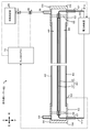
- FIG. 1 is a longitudinal sectional view of a drying furnace 10.
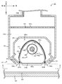
- FIG. It is an expanded sectional view of heater 30 with a nozzle.
- FIG. 3 is a cross-sectional view of the infrared heater 40 included in the nozzle-equipped heater 30 of FIG.
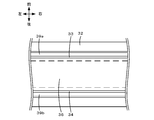
- FIG. 3 is a BB view of the nozzle-equipped heater 30 of FIG. 2 as viewed from the BB plane.
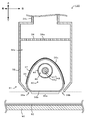
- It is sectional drawing of the heater 130 with a nozzle of a modification.
- It is sectional drawing of the heater with a nozzle 230 of a modification.
- FIG. 1 is a longitudinal sectional view of a drying furnace 10 equipped with a nozzle-equipped heater 30 according to an embodiment of the present invention.
- the drying furnace 10 performs drying of the coating film 82 applied on the sheet 80 by using infrared rays and cold air, and the upper air blower having the furnace body 14, the conveyance path 19, and the plurality of heaters 30 with nozzles. 20a, the lower air blower 20b, and a controller 70.
- the drying furnace 10 includes a roll 84 provided on the left side (front) of the furnace body 14 in FIG. 1 and a roll 86 provided on the right side (rear) of the furnace body 14 in FIG.
- the drying furnace 10 is configured as a roll-to-roll type drying furnace in which a sheet 80 on which a coating film 82 to be dried is formed is continuously conveyed by rolls 84 and 86 and dried.
- a plurality of heaters 30 with nozzles are arranged in the furnace body 14, and the heaters 30 with nozzles arranged on the upper side of the sheet 80 are arranged from the front end face 15 side.
- the heaters 30a to 30e with first to fifth nozzles are also referred to in order.
- the four nozzle-equipped heaters 30 arranged on the lower side of the sheet 80 are also referred to as sixth to ninth heaters 30f to 30i in order from the front end face 15 side.
- the furnace body 14 is a heat insulating structure formed in a substantially rectangular parallelepiped shape, and has openings 17 and 18 on the front end face 15 and the rear end face 16, respectively.
- the furnace body 14 has a length from the front end face 15 to the rear end face 16 of, for example, 2 to 10 m.
- the conveyance passage 19 is a passage from the opening 17 to the opening 18 and penetrates the furnace body 14 in the horizontal direction (left-right direction in FIG. 1).
- the sheet 80 on which the coating film 82 is applied on one side passes through the conveyance path 19.
- the sheet 80 is carried in from the opening 17 with the surface to which the coating film 82 is applied facing upward, proceeds in the furnace body 14 in the horizontal direction, and is carried out from the opening 18.
- the upper blower 20a is a device that blows cool air toward the coating film 82 and the sheet 80 that pass through the furnace body 14.
- the upper blower 20a includes an air supply fan 22a, a pipe structure 24a, and heaters 30a to 30e with first to fifth nozzles among the plurality of heaters 30 with nozzles.
- the upper blower 20a not only blows cool air but also irradiates the coating film 82 (sheet 80) with infrared rays by the heater 30 with nozzle.
- the air supply fan 22a is disposed outside the furnace body 14, is attached to the pipe structure 24a, and supplies cold air to the inside of the pipe structure 24a.
- the cold air is, for example, air at normal temperature or 50 ° C. or lower.
- the air supply fan 22a can adjust the amount of cold air generated. Air volume of cold air is not particularly limited and can be adjusted in the range of, for example, 5Nm 3 / h ⁇ 100Nm 3 / h.
- the pipe structure 24a serves as a passage for cold air from the air supply fan 22a.
- the pipe structure 24 a forms a passage from the air supply fan 22 a through the ceiling of the furnace body 14 to the inside of the furnace body 14.
- the pipe structure 24a is branched into a plurality of (five in FIG. 1) passages outside the furnace body 14, and each passage penetrates the furnace body 14 to the first to fifth heaters 30a to 30e with nozzles. Each is connected.
- the first to fifth nozzle-equipped heaters 30a to 30e are arranged substantially evenly on the upper side of the sheet 80 from the front end face 15 side to the rear end face 16 side.
- the lower blower 20 b is a device that blows cool air toward the coating film 82 and the sheet 80 that pass through the furnace body 14.
- the lower blower 20b includes an air supply fan 22b, a pipe structure 24b, and sixth to ninth heaters 30f to 30i among the plurality of heaters 30 with nozzles.
- the lower air blower 20b performs not only cool air blowing but also irradiation of infrared rays onto the coating film 82 (sheet 80) by the nozzle-equipped heater 30.
- the air supply fan 22b is disposed outside the furnace body 14, is attached to the pipe structure 24b, and supplies cold air to the inside of the pipe structure 24b.
- the cold air is, for example, air at normal temperature or 50 ° C. or lower.
- the air supply fan 22b can adjust the amount of cold air generated. Air volume of cold air is not particularly limited and can be adjusted in the range of, for example, 5Nm 3 / h ⁇ 100Nm 3 / h.
- the pipe structure 24b serves as a passage for cold air from the air supply fan 22b.
- the pipe structure 24 b forms a passage from the air supply fan 22 b through the bottom of the furnace body 14 to the inside of the furnace body 14.
- the pipe structure 24b is branched into a plurality of (four in FIG. 1) passages outside the furnace body 14, and each passage penetrates the furnace body 14 to the sixth to ninth heaters 30f to 30i with nozzles. Each is connected.
- the sixth to ninth nozzle-equipped heaters 30f to 30i are arranged substantially evenly on the lower side of the sheet 80 from the front end face 15 side to the rear end face 16 side.
- the plurality of heaters with nozzles 30 have the same configuration, and are attached so that the longitudinal direction is orthogonal to the conveyance direction (front-rear direction) of the sheet 80. It has been. Also, the heaters 30a to 30e with the first to fifth nozzles arranged on the upper side of the sheet 80 and the heaters 30f to 30i with the sixth to ninth nozzles arranged on the lower side of the sheet 80 are shifted in the conveying direction. Are alternately arranged. Therefore, the sixth to ninth nozzle-equipped heaters 30f to 30i do not exist immediately below the first to fifth nozzle-equipped heaters 30a to 30e. Hereinafter, the configuration of one nozzle-equipped heater 30 will be described.
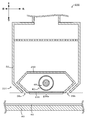
- FIG. 2 is an enlarged cross-sectional view of the heater 30 with a nozzle.
- FIG. 3 is a cross-sectional view taken along line AA of the infrared heater 40 provided in the nozzle-equipped heater 30 of FIG. 4 is a BB view of the nozzle-equipped heater 30 shown in FIG. 2 as viewed from the BB plane. 2 to 4 show the configuration of the nozzle-equipped heater 30 (the first to fifth nozzle-equipped heaters 30a to 30e) disposed above the sheet 80.
- the nozzle-equipped heater 30 (sixth to ninth nozzle-equipped heaters 30f to 30i) arranged on the lower side of the sheet 80 has a configuration in which the nozzle heater 30 arranged on the upper side of the sheet 80 is turned upside down (horizontal plane is changed). A plane-symmetric configuration). As shown in FIG. 2, the nozzle-equipped heater 30 includes an infrared heater 40 having a filament 41 that is a heating element, and an outer peripheral portion 31 that covers the infrared heater 40.
- the infrared heater 40 is a device that irradiates the coating film 82 passing through the furnace body 14 with infrared rays through the infrared transmission exposed surface 36a.
- the infrared heater 40 includes a heater body 43 formed so that an inner tube 42 surrounds a filament 41 made of tungsten, and is provided outside the heater body 43 and surrounds the inner tube 42.
- the outer tube 44 is formed as described above, and caps 50 are attached to both ends thereof.
- a space between the inner pipe 42 and the outer pipe 44 is a refrigerant flow path 49 through which a refrigerant (for example, air) can flow.
- the infrared heater 40 includes a temperature sensor 59 that detects the surface temperature of the outer tube 44 (FIG. 3).
- the inner tube 42 and the outer tube 44 are arranged concentrically, and the filament 41 is positioned at the center of the circle.
- the heater body 43 is supported at both ends by holders 55 arranged inside the cap 50.
- the heater body 43 includes infrared rays when power is supplied to the filament 41 from a power supply source 60 disposed outside the furnace body 14 and the filament 41 is heated to a predetermined temperature (eg, 1200 to 1700 ° C.). Radiates electromagnetic waves.
- the electromagnetic wave radiated by the filament 41 is not particularly limited.
- the peak wavelength is in the infrared region (the wavelength is 0.7 ⁇ m to 8 ⁇ m) or the near infrared region (the wavelength is 0.7 ⁇ m to 3.5 ⁇ m).
- an electromagnetic wave having a peak wavelength of about 3 ⁇ m is emitted.
- the inner tube 42 is a tube having a circular cross section surrounding the filament 41, and is formed of an infrared transmitting material that absorbs part of the electromagnetic waves radiated from the filament 41 and transmits infrared rays.
- the infrared transmitting material used for the inner tube 42 include germanium, silicon, sapphire, calcium fluoride, barium fluoride, zinc selenide, zinc sulfide, chalcogenide glass, and transparent alumina ceramics. Examples include transmissive quartz glass.
- the inner tube 42 is formed of quartz glass that absorbs infrared light having a wavelength exceeding 3.5 ⁇ m as a part of the electromagnetic wave and transmits infrared light having a wavelength of 3.5 ⁇ m or less as a part of the electromagnetic wave. It was supposed to be. Further, the inside of the inner tube 42 is a vacuum atmosphere or a halogen atmosphere.
- the electric wiring 41 a connected to the filament 41 is drawn out to the outside airtightly via a wiring drawing portion 57 provided in the cap 50, and is connected to the power supply source 60.
- the cap 50 is formed by integrally molding a disc-shaped lid 54 and a cylindrical portion 52 erected on the lid 54. The left and right ends of the outer tube 44 are fixed to the cylindrical portion 52.
- the outer tube 44 is a tube formed of the above-described infrared transmitting material. In the present embodiment, like the inner tube 42, it is formed of quartz glass that absorbs infrared light having a wavelength exceeding 3.5 ⁇ m and transmits infrared light having a wavelength of 3.5 ⁇ m or less.
- the outer tube 44 can be cooled to, for example, 200 ° C. or less by the refrigerant flowing through the refrigerant flow path 49.
- the refrigerant channel 49 is a space between the inner tube 42 and the outer tube 44, and the refrigerant can flow through the fluid inlet / outlet 58 provided in the cap 50.
- the refrigerant is a fluid such as air.
- the fluid inlet / outlet port 58 is disposed outside the furnace body 14 via a member such as a silicon tube that penetrates the outer peripheral portion 31 (the tubular member 36a, the fourth member 35, and the first member 32).
- a refrigerant supply source 65 is connected. The refrigerant supplied from the refrigerant supply source 65 flows into the refrigerant channel 49 from one fluid inlet / outlet 58, flows through the refrigerant channel 49, and flows out from the other fluid inlet / outlet 58.
- the refrigerant flowing through the refrigerant flow path 49 serves to directly lower the temperature of the outer tube 44 that is the outer surface of the infrared heater 40, or indirectly reduces the temperature of the infrared transmission exposed surface 36a by lowering the temperature of the outer tube 44. Play the role of lowering.
- the outer peripheral portion 31 includes first to fourth members 32 to 35, a tubular member 36 having an infrared transmission exposed surface 36a, a reflective layer 37, a rectifying plate 38, first and second members. Nozzles 39a and 39b and sealing members 90a and 90b are provided.
- the 1st member 32 is a member which constitutes the outermost periphery of heater 30 with a nozzle, and has an opening up and down. The upper opening of the first member 32 is connected to the inside of the pipe structure 24a. From the lower opening of the first member 32, the lower ends of the second and third members 33 and 34 and the infrared transmission exposed surface 36a are exposed.
- the second member 33 and the third member 34 are bent plate-like members, and are disposed between the first member 32 and the tubular member 36, respectively, and are tubular between the second member 33 and the third member 34. It arrange
- the fourth member 35 is a plate-like member that is bent so that the lower side is open, and covers the upper side of the tubular member 36 and also covers the upper side and the front and rear (left and right in FIG. 2) of the infrared heater 40. The lower end of the front side (left side shown in FIG. 2) of the fourth member 35 is joined to the upper end of the second member 33, and the lower end of the rear side (right side of FIG.
- a space 32a surrounded by the inner peripheral surface of the first member 32 and the outer peripheral surfaces of the second to fourth members 33 to 35 serves as a cool air flow path from the pipe structure 24a.
- the space 32a is divided into upper and lower portions by a current plate 38.
- the rectifying plate 38 is a flat plate member having a large number of punch holes 38a, and rectifies the cool air from the pipe structure 24a and guides it to the lower first and second nozzles 39a, 39b.
- the 1st member 32 has a side part in the edge part of the left-right direction (FIG. 4 left-right direction), and the left-right direction of the space (space 32a, 35a) inside the 1st member 32 is shown. The end is closed by this side. Further, the end portions of the second to fourth members 33 to 35 and the current plate 38 in the left-right direction are welded to the side portions.
- the first to fourth members 32 to 35 and the current plate 38 are made of metal, for example.
- the first to fourth members 32 to 35 are preferably formed of an infrared reflecting material that reflects at least infrared rays among electromagnetic waves radiated from the infrared heater 40. Examples of the infrared reflecting material include SUS304 and aluminum.
- the first nozzle 39 a is formed by the first and second members 32 and 33.
- the second nozzle 39 b is formed by the first and third members 32 and 34. That is, the first and second members 32 and 33 are nozzle forming members that form the first nozzle 39a, and the first and third members 32 and 34 are nozzle forming members that form the second nozzle 39b. Yes. Specifically, the front (left in FIG. 2) lower end of the first member 32 and the lower end of the second member 33 are separated from each other, so that the longitudinal direction is the left-right direction (left and right in FIG. 4) as shown in FIG. A slit-like first nozzle 39a parallel to the direction) is formed on the front side (upper side in FIG. 4) of the infrared transmission exposed surface 36a.
- the rear lower end of the first member 32 (right in FIG. 2) and the lower end of the third member 34 are separated from each other, so that the longitudinal direction is the left-right direction (left-right direction in FIG. 4) as shown in FIG.
- a slit-like second nozzle 39b that is parallel to the rear surface is formed on the rear side (lower side in FIG. 4) of the infrared transmission exposed surface 36a.
- the surface which faces the lower end part of the 2nd member 33 among the front lower end parts of the 1st member 32, and the surface which opposes the front lower end part of the 1st member 32 among the lower end parts of the 2nd member 33 Also, as it goes downward, it is inclined from the vertical direction (vertical direction in FIG.
- the cool air flowing through the space 32a and flowing from the first nozzle 39a mainly flows out downward and downward (downward right in FIG. 2) along this inclination.
- the surface facing the lower end portion of the third member 34 in the rear lower end portion of the first member 32 and the surface facing the rear lower end portion of the first member 32 in the lower end portion of the third member 34 are: All of them are inclined from the vertical direction (vertical direction in FIG. 2) so as to approach the infrared transmission exposed surface 36a side (front side) as it goes downward. Thereby, the cool air flowing through the space 32a and flowing from the second nozzle 39b mainly flows out downward and forward (downward left in FIG. 2) along this inclination.
- the tubular member 36 is a tubular member that covers the periphery of the infrared heater 40.
- the tubular member 36 is a member that is capable of transmitting at least a part of infrared rays among electromagnetic waves from the infrared heater 40 and is integrally formed with the above-described infrared transmitting material.
- the tubular member 36 is quartz glass that absorbs infrared light having a wavelength exceeding 3.5 ⁇ m and transmits infrared light having a wavelength of 3.5 ⁇ m or less, like the outer tube 44 and the inner tube 42 of the infrared heater 40. It was assumed that it was formed.
- the tubular member 36 has an infrared transmission exposed surface 36a on the lower side.
- the infrared transmission exposed surface 36a is formed in a planar shape, and the plane is a surface parallel to the horizontal direction (the left-right direction in FIG. 2).
- the infrared transmission exposed surface 36a and the lower ends of the first to third members 32 to 34 are located on the same horizontal plane (the vertical height is the same).
- the upper side of the tubular member 36 has a curved shape such as a parabola, an elliptical arc, or a circular arc, for example. In the present embodiment, it is assumed that it has a parabolic shape.
- the tubular member 36 has the flat plate part 36b which forms the infrared rays transmission exposure surface 36a on the lower side.
- the tubular member 36 covers a side of the filament 41 opposite to the infrared transmission exposed surface 36a as viewed from the filament 41, and a cross section perpendicular to the longitudinal direction of the filament 41 (cross section shown in FIG. 2) is a curved shape (parabolic shape). It has a curved portion 36c on the upper side.
- the tubular member 36 has a side portion at the end portion in the left-right direction (left-right direction in FIG. 4), and the end portion in the left-right direction is substantially closed by the side portion in the space inside the tubular member 36.
- the cap 50 (FIG.
- a reflective layer 37 is formed on the upper outer surface of the tubular member 36 (the outer peripheral surface of the curved portion 36c).
- the reflection layer 37 is provided on the side opposite to the infrared transmission exposed surface 36a when viewed from the filament 41, and is formed of an infrared reflection material that reflects at least a part of infrared rays among electromagnetic waves radiated from the filament 41. .
- the infrared reflecting material examples include gold, platinum, and aluminum.
- the reflective layer 37 can be formed by forming an infrared reflective material on the surface of the tubular member 36 by using a film forming method such as coating and drying, sputtering, CVD, or thermal spraying. Since the reflective layer 37 is formed on the upper surface of the tubular member 36, the cross section has a shape along the curved shape on the upper side of the tubular member 36. And the infrared heater 40 (filament 41) is arrange
- the infrared rays emitted from the filament 41 is reflected by the reflection layer 37, passes through the infrared transmission exposed surface 36a, and is efficiently irradiated onto the coating film 82.
- the tubular member 36 and the reflective layer 37 are parabolic, the infrared light reflected by the reflective layer 37 proceeds in parallel to the vertical downward direction (the downward direction in FIG. 2). The region directly below the transmission exposed surface 36a is irradiated.
- the sealing members 90a and 90b are members that seal the space 35a surrounded by the second to fourth members 33 to 35.
- the sealing member 90a is a rod-shaped member whose longitudinal direction is parallel to the left-right direction, and a lower front portion of the second member 33 and a front lower side (lower left side in FIG. 2) of the tubular member 36 having the infrared transmission exposed surface 36a. A slit-shaped opening between the two is sealed.
- the sealing member 90b is a rod-like member whose longitudinal direction is parallel to the left-right direction, and the lower rear side of the tubular member 36 having the lower end portion of the third member 34 and the infrared ray transmitting exposed surface 36a (lower right side in FIG. 2).
- the slit-shaped opening between the two is sealed.
- the sealing members 90a and 90b suppress the cold air from the first and second nozzles 39a and 39b from entering the space 35a.
- the sealing members 90a and 90b are elastic bodies, such as resin, for example.
- the sealing members 90a and 90b may be solid members with solid contents, or may be hollow members such as tubes.
- the controller 70 is configured as a microprocessor centered on a CPU.
- the controller 70 outputs control signals to the air supply fans 22a and 22b of the upper air blower 20a and the lower air blower 20b, and individually controls the temperature and air volume of the cold air generated by the air supply fans 22a and 22b.
- the controller 70 inputs the temperature of the outer pipe 44 detected by the temperature sensor 59 that is a thermocouple, and the on-off valve 67 and the flow rate provided in the middle of the pipe connecting the refrigerant supply source 65 and the fluid inlet / outlet 58.
- a control signal is output to the regulating valve 68 to individually control the flow rate of the refrigerant flowing through the refrigerant flow path 49 of the infrared heater 40 (see FIG.
- controller 70 outputs a control signal for adjusting the magnitude of the power supplied from the power supply source 60 to the filament 41 to the power supply source 60 to individually control the filament temperature of the infrared heater 40 ( (See FIG. 3). Further, the controller 70 can adjust the passage time of the coating film 82 in the furnace body 14 by controlling the rotation speed of the rolls 84 and 86.
- the sheet 80 is not particularly limited, but is a metal sheet such as aluminum or copper, for example.
- the coating film 82 on the sheet 80 is used as an electrode for a battery after drying, for example, and is not particularly limited, but is a coating film that becomes an electrode for a lithium ion secondary battery, for example.
- Examples of the coating film 82 include an electrode material paste obtained by kneading an electrode material (positive electrode active material or negative electrode active material), a binder, a conductive material, and a solvent together on the sheet 80.
- the electrode material include lithium cobaltate as the positive electrode active material, and carbon materials such as graphite as the negative electrode active material.
- the binder include polyvinylidene fluoride (PVDF).
- Examples of the conductive material include carbon powder.
- Examples of the solvent include N-methyl-2-pyrrolidone (NMP).
- the thickness of the coating film is not particularly limited, but is, for example, 20 to 1000 ⁇ m.
- the sheet 80 is unwound from the roll 84 arranged at the left end of the drying furnace 10, and a coating film 82 is applied to the upper surface by a coater (not shown) immediately before being loaded into the furnace body 14 of the drying furnace 10. Then, it is carried into the furnace body 14 through the opening 17 of the furnace body 14. Subsequently, the sheet 80 passes through the furnace body 14. At this time, the cold air from the nozzle-equipped heater 30 strikes the sheet 80 from above and below, so that the sheet 80 is conveyed while being supported in the furnace body 14 by the pressure from the cold air.
- the solvent evaporated from the coating film 82 is removed from the vicinity of the coating film 82 by the cold air from the first and second nozzles 39a and 39b of the heater 30 with nozzle, and is discharged to the outside through the openings 17 and 18.
- the coating film 82 is finally carried out from the opening 18 of the furnace body 14 and wound together with the sheet 80 on a roll 86 installed at the right end of the drying furnace 10. Further, since the cold air from the nozzle-equipped heater 30 hits the sheet 80 from above and below, the sheet 80 is supported in the furnace body 14 by the pressure from the cold air.
- both the irradiation of the infrared coating film 82 and the blowing of cold air are performed by the heater 30 with the nozzle.
- the first nozzle 39a blows cold air toward the lower right direction in FIG. 2
- the second nozzle 39b blows cold air toward the lower left direction in FIG.
- Cold air is directly applied from the first and second nozzles 39a, 39b to the region through which the coating film 82 is irradiated with infrared rays (the region immediately below the infrared transmission exposed surface 36a in FIG. 2 and the surrounding region).
- the region of the coating film 82 that is irradiated with infrared rays and the region that is directly exposed to the cold air overlap.
- the inclination angle of the lower end portions of the first to third members 32 to 34 and the distance between the nozzle-equipped heater 30 and the coating film 82 are adjusted in advance. Thereby, the solvent evaporated by infrared rays can be efficiently removed by cold air.
- the infrared heater 40 emits infrared rays, but the temperature of the outer surface of the infrared heater 40 is kept relatively low. Thereby, the overheating of the infrared transmission exposed surface 36a exposed to the outside in the heater 30 with the nozzle can be further suppressed.
- the filament 41 of the present embodiment corresponds to a heating element of the present invention
- the infrared heater 40 corresponds to an infrared heater
- the first and second nozzles 39a and 39b correspond to nozzles
- the infrared transmission exposure surface 36a is infrared transmission exposure. It corresponds to the surface
- the outer peripheral portion 31 corresponds to the outer peripheral portion
- the refrigerant flow path 49 corresponds to the refrigerant flow path.
- the tubular member 36 corresponds to a tubular member
- the first to third members 32 to 34 correspond to nozzle forming members
- the reflective layer 37 corresponds to a reflective layer
- the inner tube 42 corresponds to an inner wall.
- an example of the drying furnace of the present invention is also clarified by describing the drying furnace 10 including the nozzle-equipped heater 30.
- the infrared transmission exposed surface 36a exposed to the outside of the outer peripheral portion 31 transmits at least part of the infrared rays of the electromagnetic waves. And irradiate the outside. Moreover, the cool air as a fluid is ventilated outside from the 1st, 2nd nozzle 39a, 39b which the outer peripheral part 31 has. Thereby, infrared irradiation and ventilation can be performed with respect to the coating film 82 as a drying target. At this time, the infrared transmission exposed surface 36 a can be indirectly cooled by the refrigerant flowing through the refrigerant flow path 49.
- overheating of the infrared transmission exposed surface 36a which is a surface exposed outside can be further suppressed.
- the overheating of the drying target and the drying atmosphere is further suppressed, or the distance between the nozzle-equipped heater 30 and the coating film 82 is further reduced to improve the drying efficiency. You can make it.
- the distance between the nozzle-equipped heater 30 and the coating film 82 for example, even if the amount of cold air from the first and second nozzles 39a, 39b is reduced, the infrared rays from the infrared heater 40 are sufficient. Drying efficiency can be obtained.
- the outer peripheral portion 31 has a tubular member 36 that covers the periphery of the infrared heater 40, and at least a part of the tubular member 36 is an infrared transmission exposed surface 36 a. Thereby, the infrared heater 40 can be protected by the tubular member 36, for example, the dry atmosphere in the furnace body 14 is difficult to reach the infrared heater 40.
- first to third members 32 to 34 as nozzle forming members that do not cover the infrared transmitting exposed surface 36a and form the first and second nozzles 39a and 39b are provided.
- Sealing members 90a and 90b are provided for sealing between the tubular member 36, which is a member having the surface 36a. Thereby, since it can suppress more that the ventilation from the 1st, 2nd nozzle 39a, 39b enters into the space 35a between the nozzle formation member and the tubular member 36, it can ventilate to drying object efficiently.
- the infrared heater 40 is provided on the side opposite to the infrared transmission exposed surface 36a when viewed from the filament 41, and includes a reflective layer 37 that reflects at least a part of the infrared rays of the electromagnetic waves.
- a reflective layer 37 that reflects at least a part of the infrared rays of the electromagnetic waves.
- the cross section of the reflective layer 37 is curved and the filament 41 is disposed at the focal position or the center position of the curved surface of the reflective layer, more infrared rays can be emitted from the infrared transmission exposed surface 36a to the outside. Will increase.
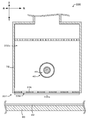
- FIG. 5 is a cross-sectional view of a nozzle heater 130 according to a modification of this case.
- the outer peripheral portion 31 does not include the second to fourth members 33 to 35, slit-shaped gaps between the first member 32 and the tubular member 36 are formed between the first nozzle 39a and the second nozzle 39b.
- the nozzle-equipped heater 130 having this configuration also has the effect of further suppressing overheating of the infrared transmission exposed surface 36a, which is a surface exposed to the outside by the refrigerant flowing through the refrigerant flow path 49, as in the present embodiment.
- the dimensional accuracy of the second and third members 32 and 33 is easier than the tubular member 36.
- a part of the integrally formed tubular member 36 is the infrared transmission exposed surface 36a, but is not limited thereto.
- the member constituting the infrared transmission exposed surface 36a may be a flat plate member, and the flat plate member and other members may be combined to surround the infrared heater 40.
- FIG. 6 is a cross-sectional view of a nozzle heater 230 according to a modification of this case. As shown in FIG. 6, in the heater 230 with the nozzle, the outer peripheral portion 231 is different from the outer peripheral portion 31 and does not include the second to fourth members 33 to 35 and the tubular member 36. Instead, the second member 233 and the flat plate member 236 are provided. It has.
- the second member 233 is a member that opens on the lower side and covers the front and rear (left and right in FIG. 6) and the upper side of the infrared heater 40.
- a flat plate member 236 is attached to the lower opening of the second member 233 so as to close the opening.
- the flat plate member 236 is formed of the above-described infrared transmitting material, and the lower surface is an infrared transmitting exposed surface 236a.
- the second member 233 and the flat plate member 236 may be bonded with an organic adhesive such as a resin to seal the gap between them.
- the first nozzle 39a is formed as a slit-like gap between the front lower end of the first member 32 (the left lower end in FIG.
- the second nozzle 39b is formed as a slit-like gap between the rear lower end of the first member 32 (the right lower end in FIG. 6) and the rear lower end of the second member 233 (the right lower end in FIG. 6).
- the nozzle-equipped heater 230 with this configuration also has the effect of further suppressing overheating of the infrared transmission exposed surface 236a, which is a surface exposed to the outside by the refrigerant flowing through the refrigerant flow path 49, as in the present embodiment.
- the infrared heater 40 is surrounded by the second member 233 and the flat plate member 236, the drying atmosphere of the furnace body 14 may enter through a slight gap between the second member 233 and the flat plate member 236. Therefore, in order to protect the infrared heater 40, it is preferable to cover the periphery of the infrared heater 40 with an integrally molded member like the tubular member 36 of the above-described embodiment.
- a reflective layer made of an infrared reflective material may be provided on the upper surface of the second member 233 (the surface facing the upper side of the infrared heater 40).
- the outer peripheral portion 31 has the first to third members 32 to 34 as nozzle forming members in addition to the tubular member 36 having the infrared transmission exposed surface 36a, but the infrared transmission exposed surface 36a. You may form a nozzle in the member which has.
- FIG. 7 is a cross-sectional view of a heater 330 with a nozzle according to a modified example in this case. As shown in FIG. 7, in the nozzle-equipped heater 330, the outer peripheral portion 331 is different from the outer peripheral portion 31 and does not include the second to fourth members 33 to 35 and the tubular member 36, and instead is provided at the opening of the first member 32. An attached flat plate member 336 is provided.
- the flat plate member 336 is formed of the infrared transmitting material described above, and the lower surface is an infrared transmitting exposed surface 336a.
- the flat plate member 336 has a number of punch holes 339, which serve as nozzles for blowing cool air.
- the nozzle-equipped heater 330 in which the nozzles are formed on the infrared transmission exposed surface in this manner also prevents overheating of the infrared transmission exposed surface 336a, which is a surface exposed to the outside by the refrigerant flowing through the refrigerant flow path 49, as in the present embodiment. A more suppressing effect can be obtained.
- the first member 32 and the flat plate member 36 may be members formed by integrally molding an infrared transmitting material. In this case, since there is no gap between the first member 32 and the flat plate member 336, it is possible to protect the infrared heater 40 by suppressing the dry atmosphere of the furnace body 14 from entering the space 332 a inside the first member 32. Can do.
- the refrigerant flow path 49 is a space between the inner tube 42 and the outer tube 44, but is not limited to this as long as the infrared transmission exposed surface 36 a can be cooled directly or indirectly.
- a space between the tubular member 36 and the outer tube 44 may be used as the refrigerant flow path.
- the direct or indirect cooling of the infrared transmissive exposed surface 36a by the refrigerant flowing through the coolant channel 49 may be performed, for example, so that the infrared transmissive exposed surface 36a is 200 ° C. or lower.
- the reflective layer 37 is formed on the outer surface on the upper side of the tubular member 36.
- the reflective layer 37 is formed on the side opposite to the infrared transmission exposed surface 36a when viewed from the infrared heater 40 (filament 41), It is not limited to this.
- it may be formed on the upper inner surface of the tubular member 36.
- the reflecting member is not limited to the one that forms a reflective layer on the surface of the tubular member 36.
- the outer tube 44 or the inner tube 42 reflects on the outer surface or inner surface opposite to the infrared transmission exposed surface 36a when viewed from the infrared heater 40.
- a layer may be formed.
- the reflective layer is not limited to the one formed on the surface of another member, and may be an independent member.
- a flat reflective layer may be disposed between the infrared heater 40 and the tubular member 36 or between the inner tube 42 and the outer tube 44.
- the reflective layer 37 since the reflective layer 37 has a parabolic shape, the infrared light reflected by the reflective layer 37 advances in parallel to the vertical downward direction (the downward direction in FIG. 2), and the infrared transmission exposed surface of the coating film 82. Although it irradiates the area
- the shape of the reflective layer 37 and the position of the filament 41 may be adjusted so that infrared rays reflected by the reflective layer 37 have a focal point. In this case, it is preferable that the distance from the filament 41 to the focal point is equal to or greater than the distance from the filament 41 to the coating film 82 (the focal point is farther from the coating film 82 when viewed from the filament 41). Is more preferably equal to the distance from the filament 41 to the coating film 82 (the focal point is located on the coating film 82).
- the inclination angle of the lower end portions of the first to third members 32 to 34 is overlapped so that the region of the coating film 82 irradiated with infrared rays from the infrared heater 40 and the region directly exposed to cold air overlap.
- the distance between the nozzle-equipped heater 30 and the coating film 82 is adjusted in advance, but is not limited thereto.
- the nozzles 39a and 39b may be formed so that the cool air is blown in the vertical direction (the vertical direction in FIG. 2) so that the region irradiated with infrared rays and the region directly hit by the cool air may not overlap.
- the region irradiated with infrared rays in the coating film 82 as in this embodiment (particularly, the region immediately below the infrared transmission exposed surface 36a). ) And an area directly hit by cold air are preferably overlapped.
- the focus of the infrared rays reflected by the reflection layer 37 described above is located on the coating film 82, the focus of the infrared rays is located on the extension of the cool air outflow direction from the first nozzle 39a and the second nozzle 39b. You may do it.
- the sheet 80 is supported in the furnace body 14 by the cold air from the heater 30 with the nozzle, but is not limited thereto.
- a plurality of support rollers that support the sheet 80 from below may be provided in the furnace body 14.
- W tungsten
- Mo molybdenum
- Ta molybdenum
- Fe—Cr—Al alloy molybdenum
- Ni—Cr alloy molybdenum
- cool air is blown from the first and second nozzles 39a and 39b, but hot air (for example, air of 50 ° C. to 200 ° C.) may be blown.
- hot air for example, air of 50 ° C. to 200 ° C.
- air is used as the refrigerant flowing through the refrigerant flow path 49 and the cold air, but an inert gas such as nitrogen may be used.
- the coating film 82 that is an electrode for the lithium ion secondary battery is illustrated as the coating film 82 that is the drying target of the heater 30 with the nozzle, but the drying target is not limited thereto.
- the sheet 80 may be made of a PET film, and the coating film 82 may be used as a thin film for MLCC (multilayer ceramic capacitor) after drying.
- the coating film 82 in this case includes, for example, ceramic powder or metal powder, an organic binder, and an organic solvent.
- the coating film 82 may be used as a thin film for LTCC (low temperature fired ceramics) or other green sheets.
- the present invention relates to industries that require heating and drying using an infrared heating device such as an infrared heater that emits infrared rays, such as the battery industry that manufactures electrode coatings for lithium ion secondary batteries, and multilayer ceramic sintered bodies.
- an infrared heating device such as an infrared heater that emits infrared rays
- the present invention can be used in the ceramic industry for manufacturing the provided multilayer ceramic capacitor.
Landscapes
- Engineering & Computer Science (AREA)
- Life Sciences & Earth Sciences (AREA)
- Microbiology (AREA)
- Mechanical Engineering (AREA)
- General Engineering & Computer Science (AREA)
- Chemical & Material Sciences (AREA)
- Combustion & Propulsion (AREA)
- Drying Of Solid Materials (AREA)
Abstract
赤外線ヒーター40のフィラメント41が電磁波を放出すると、外周部31のうち外部に露出する赤外線透過露出面36aが電磁波のうち少なくとも赤外線の一部を透過して外部に照射する。また、外周部31が有する第1,第2ノズル39a,39bから流体としての冷風を外部に送風する。このとき、赤外線透過露出面36aは冷媒流路49を流通する冷媒によって間接的に冷却が可能となっている。外周部31は、赤外線ヒーター40の周囲を覆う管状部材36を有し、管状部材36の少なくとも一部が赤外線透過露出面36aになっている。
Description
本発明は、ノズル付きヒーター及び乾燥炉に関する。
従来、送風のためのノズルとヒーターとを備えたノズル付きヒーターが知られている。例えば、特許文献1には、スリット状送風ノズルと棒状ヒーターとを並べて配置したノズル付きヒーターが記載されている。棒状ヒーターとしては、カーボンフィラメントを発熱体とする石英硝子中波長赤外線ヒーターを用いることが記載されている。このノズル付きヒーターでは、ノズルとヒーターとを備えることにより、ヒーターで乾燥対象の加熱を行うと共に、加熱により揮発した水などの成分の除去をノズルからの送風により行って、効率よく乾燥ができるとしている。
しかしながら、特許文献1のノズル付きヒーターでは、赤外線ヒーターの表面が外部に露出しており、この露出面が自身の赤外線により過熱する場合があるという問題があった。そして、赤外線ヒーターの表面の過熱が生じると、例えば乾燥対象や乾燥雰囲気が過熱する場合があった。また、乾燥対象や乾燥雰囲気の過熱を抑制するために乾燥対象とノズル付きヒーターとの距離を大きくすると、乾燥効率が低下する場合があった。
本発明はこのような課題を解決するためになされたものであり、ノズル付きヒーターにおいて、外部に露出する面の過熱をより抑制することを主目的とする。
本発明のノズル付きヒーターは、
加熱されると赤外線を含む電磁波を放出する発熱体を有する赤外線ヒーターと、
乾燥対象を乾燥させる流体を外部に送風可能な1以上のノズルと、外部に露出し前記電磁波のうち少なくとも赤外線の一部を透過して前記乾燥対象に照射可能な赤外線透過露出面と、を有し、前記赤外線ヒーターの周囲の少なくとも一部を覆う外周部と、
前記赤外線透過露出面を冷却する冷媒が流通可能な冷媒流路と、
を備えたものである。
加熱されると赤外線を含む電磁波を放出する発熱体を有する赤外線ヒーターと、
乾燥対象を乾燥させる流体を外部に送風可能な1以上のノズルと、外部に露出し前記電磁波のうち少なくとも赤外線の一部を透過して前記乾燥対象に照射可能な赤外線透過露出面と、を有し、前記赤外線ヒーターの周囲の少なくとも一部を覆う外周部と、
前記赤外線透過露出面を冷却する冷媒が流通可能な冷媒流路と、
を備えたものである。
この本発明のノズル付きヒーターでは、赤外線ヒーターの発熱体が赤外線を含む電磁波を放出すると、外周部のうち外部に露出する赤外線透過露出面が電磁波のうち少なくとも赤外線の一部を透過して外部に照射する。また、外周部が有する1以上のノズルから流体を外部に送風する。これにより、乾燥対象に対して赤外線の照射と送風とが可能となっている。また、このとき、赤外線透過露出面は冷媒流路を流通する冷媒によって冷却が可能となっている。これにより、外部に露出する面である赤外線透過露出面の過熱をより抑制することができる。そして、赤外線透過露出面の過熱をより抑制することで、例えば乾燥対象や乾燥雰囲気の過熱をより抑制したり、ノズル付きヒーターと乾燥対象との距離をより小さくして乾燥効率を向上させたりすることができる。ここで、前記電磁波は、ピーク波長が赤外線領域(例えば、波長が0.7μm~8μmの領域)にあるものとしてもよいし、ピーク波長が近赤外線領域(例えば、波長が0.7μm~3.5μmの領域)にあるものとしてもよい。また、本発明のノズル付きヒーターは、前記冷媒流路に流す冷媒の量を調整する流量調整手段を備えるものとしてもよい。
本発明のノズル付きヒーターにおいて、前記外周部は、前記赤外線ヒーターの周囲を覆う管状部材を有し、該管状部材の少なくとも一部が前記赤外線透過露出面になっていてもよい。こうすれば、例えば乾燥雰囲気が赤外線ヒーターに到達しにくくなるなど、赤外線ヒーターを管状部材で保護することができる。この場合において、前記管状部材は、少なくとも赤外線の一部を透過可能な赤外線透過材料を一体成形した部材であるものとしてもよい。こうすれば、例えば管状部材が複数の部材を接合して形成した部材である場合に比べて、接合による隙間などが形成されないため、赤外線ヒーターを保護する効果が高まる。この場合において、前記管状部材は、平面状の前記赤外線透過露出面を形成する平板部と、前記発熱体のうち該発熱体からみて前記赤外線透過露出面とは反対側を覆い且つ前記発熱体の長手方向に垂直な断面が曲線形状をしている湾曲部と、を有していてもよい。さらに、前記湾曲部の内周面又は外周面に設けられ、前記電磁波のうち少なくとも赤外線の一部を反射する反射層を有していてもよい。
本発明のノズル付きヒーターにおいて、前記外周部は、前記赤外線透過露出面を覆わず且つ前記ノズルを形成するノズル形成部材を有していてもよい。この場合において、前記外周部は、前記ノズル形成部材と前記赤外線透過露出面を有する部材との間を封止する封止部材を有してもよい。こうすれば、ノズルからの送風がノズル形成部材と前記赤外線透過露出面を有する部材との間に入り込むことをより抑制できるため、乾燥対象に効率よく送風することができる。
本発明のノズル付きヒーターにおいて、前記ノズルは、前記赤外線透過露出面に形成されていてもよい。
本発明のノズル付きヒーターにおいて、前記発熱体からみて前記赤外線透過露出面とは反対側に設けられ、該電磁波のうち少なくとも赤外線の一部を反射する反射層、を備えたものとしてもよい。こうすれば、赤外線透過露出面には、発熱体から直接放出される赤外線と反射層により反射された赤外線とが放射されることになり、赤外線透過露出面から外部へより多くの赤外線を放出でき、乾燥対象をより効率よく乾燥できる。この場合において、前記反射層は、例えば断面形状が円弧等の曲線状の板状部材であってもよいし、平板状の部材であってもよい。反射層の断面が曲線状である場合には、反射層の曲面の焦点位置又は中心位置に前記発熱体が配置されているものとしてもよい。こうすることで、赤外線透過露出面から外部へより多くの赤外線を放出できる効果が高まる。また、前記外周部が前記管状部材を有する構成の場合には、前記反射層は、該管状部材の内周面に形成してもよいし、外周面に形成してもよい。
本発明のノズル付きヒーターにおいて、前記赤外線ヒーターは、前記赤外線透過露出面と前記発熱体との間に配置され前記電磁波のうち少なくとも赤外線の一部を透過可能な内壁を有し、前記冷媒流路は、前記赤外線透過露出面と前記内壁との間の空間の少なくとも一部に設けられた流路としてもよい。この場合において、前記冷媒流路を流通する冷媒は、赤外線透過露出面を直接的に冷却するものとしてもよいし、例えば内壁など赤外線透過露出面と発熱体との間の物体を冷却することで赤外線透過露出面を間接的に冷却するものとしてもよい。間接的に冷却する場合、例えば、前記赤外線ヒーターは、前記内壁と前記赤外線透過露出面との間に配置され前記電磁波のうち少なくとも赤外線の一部を透過可能な外壁を有し、前記冷媒流路は、前記外壁と前記内壁との間の空間としてもよい。
本発明のノズル付きヒーターにおいて、前記赤外線透過露出面は、前記発熱体とは反対側に凸となる曲面としてもよいし、前記発熱体側に凸となる曲面としてもよいし、平面としてもよい。
本発明の乾燥炉は、上述したいずれかの態様の本発明のノズル付きヒーターを備えたものである。そのため、本発明の乾燥炉は、本発明のノズル付きヒーターと同様の効果、例えば、外部に露出する面である赤外線透過露出面の過熱をより抑制する効果が得られる。
次に、本発明の実施形態について、図面を用いて説明する。図1は、本発明の一実施形態であるノズル付きヒーター30を備えた乾燥炉10の縦断面図である。乾燥炉10は、シート80上に塗布された塗膜82の乾燥を赤外線及び冷風を用いて行うものであり、炉体14と、搬送通路19と、複数のノズル付きヒーター30を有する上側送風装置20a及び下側送風装置20bと、コントローラー70と、を備えている。また、乾燥炉10は、炉体14の図1における左側(前方)に設けられたロール84と、炉体14の図1における右側(後方)に設けられたロール86と、を備えている。乾燥炉10は、乾燥対象となる塗膜82が上面に形成されたシート80を、ロール84,86により連続的に搬送して乾燥を行うロールトゥロール方式の乾燥炉として構成されている。なお、ノズル付きヒーター30は、炉体14内に複数本(図1では9本)配置されており、そのうちシート80の上側に配置された5本のノズル付きヒーター30は、前端面15側から順に第1~第5ノズル付きヒーター30a~30eとも称する。また、シート80の下側に配置された4本のノズル付きヒーター30は、前端面15側から順に第6~第9ノズル付きヒーター30f~30iとも称する。
炉体14は、略直方体に形成された断熱構造体であり、前端面15及び後端面16にそれぞれ開口17,18を有している。この炉体14は、前端面15から後端面16までの長さが例えば2~10mである。
搬送通路19は、開口17から開口18に至る通路であり、炉体14を水平方向(図1の左右方向)に貫通している。片面に塗膜82が塗布されたシート80は、この搬送通路19を通過していく。シート80は、塗膜82が塗布された面を上にして、開口17から搬入され、炉体14の内部を水平方向に進行し、開口18から搬出される。
上側送風装置20aは、炉体14内を通過する塗膜82やシート80に向けて冷風を送風する装置である。上側送風装置20aは、給気ファン22aと、パイプ構造体24aと、複数のノズル付きヒーター30のうち第1~第5ノズル付きヒーター30a~30eと、を備えている。この上側送風装置20aは、冷風の送風だけでなく、ノズル付きヒーター30による塗膜82(シート80)への赤外線の照射も行う。給気ファン22aは、炉体14の外部に配置され、パイプ構造体24aに取り付けられており、冷風をパイプ構造体24aの内部へ供給するものである。冷風は、例えば常温や50℃以下の空気である。給気ファン22aは、発生させる冷風の風量の調節が可能となっている。冷風の風量は、特に限定するものではないが、例えば5Nm3/h~100Nm3/hの範囲で調節可能である。パイプ構造体24aは、給気ファン22aからの冷風の通路となるものである。パイプ構造体24aは、給気ファン22aから炉体14の天井を貫通して炉体14の内部までの通路を形成している。パイプ構造体24aは、炉体14の外部において複数(図1では5つ)の通路に分岐しており、各通路が炉体14を貫通して第1~第5ノズル付きヒーター30a~30eにそれぞれ接続されている。第1~第5ノズル付きヒーター30a~30eは、シート80の上側において前端面15側から後端面16側にわたって略均等に配置されている。
下側送風装置20bは、炉体14内を通過する塗膜82やシート80に向けて冷風を送風する装置である。下側送風装置20bは、給気ファン22bと、パイプ構造体24bと、複数のノズル付きヒーター30のうち第6~第9ノズル付きヒーター30f~30iと、を備えている。この下側送風装置20bは、冷風の送風だけでなく、ノズル付きヒーター30による塗膜82(シート80)への赤外線の照射も行う。給気ファン22bは、炉体14の外部に配置され、パイプ構造体24bに取り付けられており、冷風をパイプ構造体24bの内部へ供給するものである。冷風は、例えば常温や50℃以下の空気である。給気ファン22bは、発生させる冷風の風量の調節が可能となっている。冷風の風量は、特に限定するものではないが、例えば5Nm3/h~100Nm3/hの範囲で調節可能である。パイプ構造体24bは、給気ファン22bからの冷風の通路となるものである。パイプ構造体24bは、給気ファン22bから炉体14の底部を貫通して炉体14の内部までの通路を形成している。パイプ構造体24bは、炉体14の外部において複数(図1では4つ)の通路に分岐しており、各通路が炉体14を貫通して第6~第9ノズル付きヒーター30f~30iにそれぞれ接続されている。第6~第9ノズル付きヒーター30f~30iは、シート80の下側において前端面15側から後端面16側にわたって略均等に配置されている。
複数のノズル付きヒーター30(第1~第9ノズル付きヒーター30a~30i)は、同様の構成を有しており、いずれも長手方向がシート80の搬送方向(前後方向)と直交するように取り付けられている。また、シート80の上側に配置された第1~第5ノズル付きヒーター30a~30eと、シート80の下側に配置された第6~第9ノズル付きヒーター30f~30iとは、搬送方向にずれて交互に配置されている。そのため、第1~第5ノズル付きヒーター30a~30eの真下には第6~第9ノズル付きヒーター30f~30iは存在しない。以下、1つのノズル付きヒーター30の構成について説明する。
図2は、ノズル付きヒーター30の拡大断面図である。また、図3は、図2のノズル付きヒーター30が備える赤外線ヒーター40のA-A断面図である。図4は、図2のノズル付きヒーター30をB-B面から見たBB視図である。なお、図2~4は、いずれもシート80の上側に配置されたノズル付きヒーター30(第1~第5ノズル付きヒーター30a~30e)の構成を示している。シート80の下側に配置されたノズル付きヒーター30(第6~第9ノズル付きヒーター30f~30i)は、シート80の上側に配置されたノズル付きヒーター30の上下を逆にした構成(水平面を対称面として面対称な構成)を有している。ノズル付きヒーター30は、図2に示すように、発熱体であるフィラメント41を有する赤外線ヒーター40と、赤外線ヒーター40を覆う外周部31と、を備えている。
赤外線ヒーター40は、炉体14内を通過する塗膜82に赤外線透過露出面36aを介して赤外線を照射する装置である。赤外線ヒーター40は、図2,図3に示すように、タングステン製のフィラメント41を内管42が囲むように形成されたヒーター本体43と、このヒーター本体43の外側に設けられ内管42を囲むように形成された外管44と、を備えており、これらの両端にはキャップ50が取り付けられている。内管42と外管44との間の空間は、冷媒(例えば空気)を流通可能な冷媒流路49となっている。また、赤外線ヒーター40は、外管44の表面温度を検出する温度センサ59を備えている(図3)。なお、内管42,外管44は同心円状に配置されており、その円の中心にフィラメント41が位置するようになっている。
ヒーター本体43は、両端がキャップ50の内部に配置されたホルダー55に支持されている。このヒーター本体43は、炉体14の外部に配置された電力供給源60からフィラメント41へ電力が供給されて、フィラメント41が所定温度(例えば1200~1700℃)に加熱されると、赤外線を含む電磁波を放射する。フィラメント41が放射する電磁波は、特に限定するものではないが、例えば、ピーク波長が赤外線領域(波長が0.7μm~8μmの領域)や近赤外線領域(波長が0.7μm~3.5μmの領域)にあるものである。本実施形態では、ピーク波長が3μm付近の電磁波を放射するものとした。内管42は、フィラメント41を囲む断面円形の管であり、フィラメント41から放射された電磁波の一部を吸収し且つ赤外線を透過する赤外線透過材料で形成されている。内管42に用いるこのような赤外線透過材料としては、例えば、ゲルマニウム、シリコン、サファイア、フッ化カルシウム、フッ化バリウム、セレン化亜鉛、硫化亜鉛、カルコゲナイドガラス、透過性アルミナセラミックスなどのほか、赤外線を透過可能な石英ガラスなどが挙げられる。本実施形態では、内管42は、上述した赤外線透過材料のうち、電磁波の一部として波長が3.5μmを超える赤外線を吸収し且つ3.5μm以下の赤外線については透過する石英ガラスで形成されているものとした。また、内管42の内部は、真空雰囲気又はハロゲン雰囲気となっている。このフィラメント41に接続された電気配線41aは、キャップ50に設けられた配線引出部57を介して気密に外部へ引き出され、電力供給源60に接続されている。キャップ50は、図3に示すように、円盤状の蓋54と、その蓋54に立設された円筒部52とを一体成形したものである。外管44の左右両端は、円筒部52に固定されている。
外管44は、上述した赤外線透過材料で形成された管である。本実施形態では、内管42と同様に、波長が3.5μmを超える赤外線を吸収し且つ3.5μm以下の赤外線については透過する石英ガラスで形成されているものとした。なお、外管44は、冷媒流路49を流れる冷媒によって、例えば200℃以下に冷却可能になっている。
冷媒流路49は、内管42と外管44との間の空間であり、キャップ50に設けられた流体出入口58を通じて冷媒が流通可能となっている。冷媒は、例えば空気などの流体である。流体出入口58は、図示は省略するが外周部31(管状部材36a,第4部材35,第1部材32)を貫通する例えばシリコンチューブなどの部材を介して、炉体14の外部に配置された冷媒供給源65と接続されている。この冷媒供給源65から供給された冷媒は、一方の流体出入口58から冷媒流路49内に流入し、冷媒流路49内を流通して他方の流体出入口58から流出する。冷媒流路49を流通する冷媒は、赤外線ヒーター40の外面である外管44の温度を直接的に下げる役割や、外管44の温度を下げることで赤外線透過露出面36aの温度を間接的に下げる役割を果たす。
外周部31は、図2に示すように、第1~第4部材32~35と、赤外線透過露出面36aを有する管状部材36と、反射層37と、整流板38と、第1,第2ノズル39a,39bと、封止部材90a,90bと、を備えている。第1部材32は、ノズル付きヒーター30の最外周を構成する部材であり、上下に開口を有している。第1部材32の上側の開口は、パイプ構造体24aの内部に接続されている。第1部材32の下側の開口からは、第2,第3部材33,34の下端及び赤外線透過露出面36aが露出している。第2部材33,第3部材34は、屈曲した板状の部材であり、それぞれ第1部材32と管状部材36との間に配置されると共に、第2部材33と第3部材34とで管状部材36を前後(図2の左右)から挟むように配置されている。第4部材35は、下側が開口するように屈曲した板状の部材であり、管状部材36の上側を覆うと共に赤外線ヒーター40の上側及び前後(図2の左右)を覆っている。第4部材35は、前側(図2に示す左側)の下端が第2部材33の上端と接合され、後側(図2の右側)の下端が第3部材34の上端と接合されている。第4部材35と第2部材33,第3部材34とは、例えば溶接などにより接合されている。これにより、第1部材32の内周面と第2~第4部材33~35の外周面とで囲まれる空間32aは、パイプ構造体24aからの冷風の流路となっている。この空間32aは、整流板38により上下に区切られている。整流板38は、多数のパンチ孔38aが空けられた平板状の部材であり、パイプ構造体24aからの冷風を整流して下方の第1,第2ノズル39a,39bへ導く。なお、図示は省略するが、第1部材32は左右方向(図4の左右方向)の端部に側部を有し、第1部材32の内部の空間(空間32a,35a)の左右方向の端部はこの側部により閉じられている。また、第2~第4部材33~35,整流板38の左右方向の端部は、この側部に溶接されている。第1~第4部材32~35及び整流板38の材料は例えば金属である。また、第1~第4部材32~35は、赤外線ヒーター40から放射される電磁波のうち少なくとも赤外線を反射する赤外線反射材料で形成することが好ましい。赤外線反射材料としては、例えばSUS304やアルミニウムなどが挙げられる。
第1ノズル39aは、第1,第2部材32,33により形成されている。第2ノズル39bは、第1,第3部材32,34により形成されている。すなわち、第1,第2部材32,33は第1ノズル39aを形成するノズル形成部材となっており、第1,第3部材32,34は第2ノズル39bを形成するノズル形成部材となっている。具体的には、第1部材32の前(図2の左)下端と第2部材33の下端とは離間しており、これにより図4に示すように長手方向が左右方向(図4の左右方向)と平行なスリット状の第1ノズル39aが赤外線透過露出面36aの前側(図4の上側)に形成されている。同様に、第1部材32の後(図2の右)下端と第3部材34の下端とは離間しており、これにより図4に示すように長手方向が左右方向(図4の左右方向)と平行なスリット状の第2ノズル39bが赤外線透過露出面36aの後側(図4の下側)に形成されている。また、第1部材32の前下端部のうち第2部材33の下端部に対向する面と、第2部材33の下端部のうち第1部材32の前下端部に対向する面とは、いずれも下方に進むにつれて赤外線透過露出面36a側(後方)に近づくように垂直方向(図2の上下方向)から傾斜している。これにより、空間32aを通過して第1ノズル39aから流れる冷風は、この傾斜に沿って主に後方下向き(図2の右下方向)に流出する。同様に、第1部材32の後下端部のうち第3部材34の下端部に対向する面と、第3部材34の下端部のうち第1部材32の後下端部に対向する面とは、いずれも下方に進むにつれて赤外線透過露出面36a側(前方)に近づくように垂直方向(図2の上下方向)から傾斜している。これにより、空間32aを通過して第2ノズル39bから流れる冷風は、この傾斜に沿って主に前方下向き(図2の左下方向)に流出する。
管状部材36は、赤外線ヒーター40の周囲を覆う管状の部材である。管状部材36は、赤外線ヒーター40からの電磁波のうち少なくとも赤外線の一部を透過可能であり、上述した赤外線透過材料を一体成形した部材である。本実施形態では、管状部材36は、赤外線ヒーター40の外管44及び内管42と同様に、波長が3.5μmを超える赤外線を吸収し且つ3.5μm以下の赤外線については透過する石英ガラスで形成されているものとした。この管状部材36は、下側に赤外線透過露出面36aを有している。赤外線透過露出面36aは、平面状に形成されており、その平面は水平方向(図2の左右方向)と平行な面になっている。赤外線透過露出面36aと、第1~第3部材32~34の下端とは、同じ水平面上に位置している(鉛直方向の高さが同じになっている)。また、管状部材36の上側は、断面形状が例えばパラボラ、楕円の弧、円弧等の曲線形状となっている。本実施形態では、パラボラ形状になっているものとした。このように、管状部材36は、赤外線透過露出面36aを形成する平板部36bを下側に有している。また、管状部材36は、フィラメント41のうちフィラメント41からみて赤外線透過露出面36aとは反対側を覆い且つフィラメント41の長手方向に垂直な断面(図2に示す断面)が曲線形状(パラボラ形状)をしている湾曲部36cを上側に有している。管状部材36は、図示は省略するが左右方向(図4の左右方向)の端部に側部を有し、管状部材36の内部の空間は左右方向の端部がこの側部によりほぼ閉じられている。また、赤外線ヒーター40のキャップ50(図3)は管状部材36の側部を貫通しており、この側部が赤外線ヒーター40を支持している。さらに、管状部材36は、この両端の側部が第1部材32の両端の側部に挟まれており、第1部材32の側部によって管状部材36が保持されている。管状部材36の上側の外表面(湾曲部36cの外周面)には、反射層37が形成されている。この反射層37は、フィラメント41からみて赤外線透過露出面36aとは反対側に設けられており、フィラメント41から放射される電磁波のうち少なくとも赤外線の一部を反射する赤外線反射材料で形成されている。赤外線反射材料としては、例えば金,白金,アルミニウムなどが挙げられる。反射層37は、管状部材36の表面に塗布乾燥、スパッタリングやCVD、溶射といった成膜方法を用いて赤外線反射材料を成膜することで形成することができる。反射層37は、管状部材36の上側の表面に形成されているため、断面は管状部材36の上側の曲線形状に沿った形状をしている。そして、その曲線形状の焦点もしくは中心位置に赤外線ヒーター40(フィラメント41)が配置されている。そのため、フィラメント41から発せられた赤外線の一部は、反射層37で反射され、赤外線透過露出面36aを透過して効率的に塗膜82へ照射される。本実施形態では、管状部材36及び反射層37がパラボラ形状であるため、反射層37で反射した赤外線は鉛直下方向(図2の下方向)に平行に進んでいき、塗膜82のうち赤外線透過露出面36aの直下の領域に照射される。
封止部材90a,90bは、第2~第4部材33~35で囲まれる空間35aを封止する部材である。封止部材90aは、長手方向が左右方向と平行な棒状の部材であり、第2部材33の下端部と赤外線透過露出面36aを有する管状部材36の前下側(図2の左下側)との間のスリット状の開口を封止している。封止部材90bは、長手方向が左右方向と平行な棒状の部材であり、第3部材34の下端部と赤外線透過露出面36aを有する管状部材36の後下側(図2の右下側)との間のスリット状の開口を封止している。これにより、封止部材90a,90bは、第1,第2ノズル39a,39bからの冷風が空間35a内に進入するのを抑制している。封止部材90a,90bは、例えば樹脂などの弾性体である。なお、封止部材90a,90bは中身の詰まった中実の部材であってもよいし、例えばチューブ状など中空の部材であってもよい。
コントローラー70は、CPUを中心とするマイクロプロセッサーとして構成されている。このコントローラー70は、上側送風装置20a,下側送風装置20bの給気ファン22a,22bに制御信号を出力して、給気ファン22a,22bで発生させる冷風の温度及び風量を個別に制御する。また、コントローラー70は、熱電対である温度センサ59が検出した外管44の温度を入力したり、冷媒供給源65と流体出入口58とを接続する配管の途中に設けられた開閉弁67及び流量調整弁68に制御信号を出力したりして、赤外線ヒーター40の冷媒流路49を流れる冷媒の流量を個別に制御する(図3参照)。更に、コントローラー70は、電力供給源60からフィラメント41へ供給される電力の大きさを調整するための制御信号を電力供給源60へ出力して、赤外線ヒーター40のフィラメント温度を個別に制御する(図3参照)。また、コントローラー70は、ロール84,86の回転速度を制御することで炉体14内の塗膜82の通過時間を調整することができる。
シート80は、特に限定するものではないが、例えば、アルミニウムや銅等の金属シートである。また、シート80上の塗膜82は、例えば乾燥後に電池用の電極として用いられるものであり、特に限定するものではないが、例えばリチウムイオン二次電池用の電極となる塗膜である。塗膜82としては、例えば、電極材(正極活物質又は負極活物質)とバインダーと導電材と溶剤とを共に混練した電極材ペーストを、シート80上に塗布したもの等が挙げられる。電極材は、正極活物質としてはコバルト酸リチウムなどが挙げられ、負極活物質としてはグラファイトなどの炭素材が挙げられる。バインダーとしては、ポリフッ化ビニリデン(PVDF)などが挙げられる。導電材としては、カーボン粉末などが挙げられる。溶剤としては、N-メチル-2-ピロリドン(NMP)などが挙げられる。塗膜の厚みは、特に限定するものではないが、例えば20~1000μmである。
次に、こうして構成された乾燥炉10を用いて塗膜82を乾燥する様子について説明する。まず、図1において、乾燥炉10の左端に配置されたロール84からシート80が巻き外され、乾燥炉10の炉体14に搬入される直前に図示しないコーターによって上面に塗膜82が塗布され、炉体14の開口17を通って炉体14内へ搬入される。続いて、シート80は、炉体14内を通過する。このとき、ノズル付きヒーター30からの冷風が、シート80に上下から当たることで、この冷風からの圧力により炉体14内でシート80が支持されつつ搬送される。そして、その間にノズル付きヒーター30からの赤外線や冷風の作用により塗膜82から溶剤が蒸発する。塗膜82から蒸発した溶剤はノズル付きヒーター30の第1,第2ノズル39a,39bからの冷風により塗膜82付近から除去され、開口17,18から外部へ排出される。塗膜82は、最終的に炉体14の開口18から搬出され、乾燥炉10の右端に設置されたロール86にシート80とともに巻き取られる。また、ノズル付きヒーター30からの冷風は、シート80に上下から当たるため、この冷風からの圧力により炉体14内でシート80が支持される。
このようにして塗膜82を乾燥する際、ノズル付きヒーター30によって赤外線の塗膜82への照射と冷風の送風の両方が行われる。しかも、第1ノズル39aは図2の右下方向に向かって冷風を送風し、第2ノズル39bは図2の左下方向に向かって冷風を送風するから、赤外線ヒーター40から赤外線透過露出面36aを透過して塗膜82に赤外線が照射される領域(図2における赤外線透過露出面36aの直下の領域及びその周辺の領域)に第1,第2ノズル39a,39bから直接冷風が当たることになる。換言すると、本実施形態では、塗膜82のうち赤外線が照射される領域と冷風が直接当たる領域(第1ノズル39a,第2ノズル39bからの冷風の流出方向の延長上の領域)とが重なるように、第1~第3部材32~34の下端部の傾斜角やノズル付きヒーター30と塗膜82との距離が予め調整されている。これにより、赤外線により蒸発した溶剤を冷風によって効率よく除去できる。また、冷媒流路49を流れる冷媒によって外管44が直接冷却されているため、赤外線ヒーター40から赤外線は放射されるものの赤外線ヒーター40の外表面の温度は比較的低温に保たれる。これにより、ノズル付きヒーター30のうち外部に露出する赤外線透過露出面36aの過熱をより抑制することができる。
ここで、本実施形態の構成要素と本発明の構成要素との対応関係を明らかにする。本実施形態のフィラメント41が本発明の発熱体に相当し、赤外線ヒーター40が赤外線ヒーターに相当し、第1,第2ノズル39a,39bがノズルに相当し、赤外線透過露出面36aが赤外線透過露出面に相当し、外周部31が外周部に相当し、冷媒流路49が冷媒流路に相当する。また、管状部材36が管状部材に相当し、第1~第3部材32~34がノズル形成部材に相当し、反射層37が反射層に相当し、内管42が内壁に相当する。なお、本実施形態では、ノズル付きヒーター30を備えた乾燥炉10についても説明することにより、本発明の乾燥炉の一例も明らかにしている。
以上説明した本実施形態のノズル付きヒーター30では、赤外線ヒーター40のフィラメント41が電磁波を放出すると、外周部31のうち外部に露出する赤外線透過露出面36aが電磁波のうち少なくとも赤外線の一部を透過して外部に照射する。また、外周部31が有する第1,第2ノズル39a,39bから流体としての冷風を外部に送風する。これにより、乾燥対象としての塗膜82に対して赤外線の照射と送風とが可能となっている。また、このとき、赤外線透過露出面36aは冷媒流路49を流通する冷媒によって間接的に冷却が可能となっている。これにより、外部に露出する面である赤外線透過露出面36aの過熱をより抑制することができる。なお、赤外線透過露出面36aの加熱をより抑制することで、例えば乾燥対象や乾燥雰囲気の過熱をより抑制したり、ノズル付きヒーター30と塗膜82との距離をより小さくして乾燥効率を向上させたりすることができる。また、ノズル付きヒーター30と塗膜82との距離をより小さくすることで、例えば第1,第2ノズル39a,39bからの冷風の風量をより小さくしても赤外線ヒーター40からの赤外線により十分な乾燥効率を得ることができる。さらに、第1,第2ノズル39a,39bからの冷風の風量をより小さくすることで、炉体14内を通過する塗膜82(シート80)が冷風で撓むのをより抑制することができる。
また、外周部31は、赤外線ヒーター40の周囲を覆う管状部材36を有し、管状部材36の少なくとも一部が赤外線透過露出面36aになっている。これにより、例えば炉体14内の乾燥雰囲気が赤外線ヒーター40に到達しにくくなるなど、赤外線ヒーター40を管状部材36で保護することができる。
さらに、赤外線透過露出面36aを覆わず且つ第1,第2ノズル39a,39bを形成するノズル形成部材としての第1~第3部材32~34を有しており、ノズル形成部材と赤外線透過露出面36aを有する部材である管状部材36との間を封止する封止部材90a,90bを有している。これにより、第1,第2ノズル39a,39bからの送風がノズル形成部材と管状部材36との間の空間35aに入り込むことをより抑制できるため、乾燥対象に効率よく送風することができる。
さらにまた、赤外線ヒーター40は、フィラメント41からみて赤外線透過露出面36aとは反対側に設けられ、電磁波のうち少なくとも赤外線の一部を反射する反射層37を備えている。これにより、赤外線透過露出面36aには、フィラメント41から直接放出される赤外線と反射層37により反射された赤外線とが放射されることになり、赤外線透過露出面36aから外部へより多くの赤外線を放出でき、塗膜82をより効率よく乾燥できる。しかも、反射層37の断面は曲線状であって、反射層の曲面の焦点位置又は中心位置にフィラメント41が配置されているため、赤外線透過露出面36aから外部へより多くの赤外線を放出できる効果が高まる。
なお、本発明は上述した実施形態に何ら限定されることはなく、本発明の技術的範囲に属する限り種々の態様で実施し得ることはいうまでもない。
例えば、上述した実施形態において、外周部31が第2~第4部材33~35を備えないものとしてもよい。図5は、この場合の変形例のノズル付きヒーター130の断面図である。図5に示すように、外周部31が第2~第4部材33~35を備えない場合、第1部材32と管状部材36とのスリット状の隙間が第1ノズル39a,第2ノズル39bとなる。この構成のノズル付きヒーター130でも、本実施形態と同様に、冷媒流路49を流れる冷媒により外部に露出する面である赤外線透過露出面36aの過熱をより抑制する効果が得られる。ただし、例えば管状部材36を石英ガラスで形成する場合、管状部材36よりも第2,第3部材32,33の方が寸法精度を高くしやすい。そのため、図5において第1部材32と管状部材36との間隔(=第1ノズル39aや第2ノズル39bノズルの開口の大きさ)が一定値になるように調整するよりも、図2において第1部材32と第2部材33との間隔や第1部材32と第2部材34との間隔が一定値になるよう調整する方が比較的容易である。したがって、本実施形態のように外周部31が第2~第3部材33~34を備えるなど、赤外線透過露出面を構成する部材以外の部材でノズルを形成する方が、ノズルの開口の寸法精度を高くしやすい。
上述した実施形態では、一体成形された管状部材36の一部が赤外線透過露出面36aとなっていたが、これに限られない。例えば、赤外線透過露出面36aを構成する部材は平板状の部材とし、この平板状の部材と他の部材とを併せて赤外線ヒーター40を囲むものとしてもよい。図6は、この場合の変形例のノズル付きヒーター230の断面図である。図6に示すように、ノズル付きヒーター230では、外周部231が外周部31とは異なり第2~第4部材33~35及び管状部材36を備えず、代わりに第2部材233及び平板部材236を備えている。第2部材233は、下側が開口し赤外線ヒーター40の前後(図6の左右)及び上側を覆う部材である。第2部材233の下側の開口には、開口を塞ぐように平板部材236が取り付けられている。この平板部材236は、上述した赤外線透過材料で形成されており、下面が赤外線透過露出面236aとなっている。なお、第2部材233と平板部材236とを例えば樹脂などの有機接着剤で接着して、両者の隙間を封止するものとしてもよい。また、第1ノズル39aは、第1部材32の前下端(図6の左下端)と第2部材233の前下端(図6の左下端)とのスリット状の隙間として形成されている。第2ノズル39bは、第1部材32の後下端(図6の右下端)と第2部材233の後下端(図6の右下端)とのスリット状の隙間として形成されている。この構成のノズル付きヒーター230でも、本実施形態と同様に、冷媒流路49を流れる冷媒により外部に露出する面である赤外線透過露出面236aの過熱をより抑制する効果が得られる。ただし、赤外線ヒーター40は第2部材233と平板部材236とで囲まれているものの、第2部材233と平板部材236とのわずかな隙間から炉体14の乾燥雰囲気が入り込む場合がある。そのため、赤外線ヒーター40を保護するためには、上述した実施形態の管状部材36のように、赤外線ヒーター40の周囲を一体成形された部材で覆うことが好ましい。なお、第2部材233の上面(赤外線ヒーター40の上側と対向する面)に赤外線反射材料で形成された反射層を設けてもよい。
上述した実施形態では、外周部31は、赤外線透過露出面36aを有する管状部材36とは別にノズル形成部材としての第1~第3部材32~34を有するものとしたが、赤外線透過露出面36aを有する部材にノズルを形成してもよい。図7は、この場合の変形例のノズル付きヒーター330の断面図である。図7に示すように、ノズル付きヒーター330では、外周部331が外周部31とは異なり第2~第4部材33~35及び管状部材36を備えず、代わりに第1部材32の開口部に取り付けられた平板部材336を備えている。この平板部材336は、上述した赤外線透過材料で形成されており、下面が赤外線透過露出面336aとなっている。また、平板部材336には、多数のパンチ孔339が形成されており、このパンチ孔339が冷風を送風するノズルとなっている。このように赤外線透過露出面にノズルを形成した態様のノズル付きヒーター330でも、本実施形態と同様に、冷媒流路49を流れる冷媒により外部に露出する面である赤外線透過露出面336aの過熱をより抑制する効果が得られる。なお、この場合において、第1部材32と平板部材36とが、赤外線透過材料を一体成形した部材であるものとしてもよい。こうすれば、第1部材32と平板部材336との隙間がないため、炉体14の乾燥雰囲気が第1部材32の内部である空間332aに入り込むことを抑制して赤外線ヒーター40を保護することができる。
上述した実施形態では、冷媒流路49は内管42と外管44との間の空間であるものとしたが、直接的又は間接的に赤外線透過露出面36aを冷却できれば、これに限られない。例えば、管状部材36と外管44との間の空間を冷媒流路としてもよい。なお、冷媒流路49を流れる冷媒による直接的又は間接的な赤外線透過露出面36aの冷却は、例えば赤外線透過露出面36aが200℃以下になるように行うものとしてもよい。
上述した実施形態では、反射層37は、管状部材36の上側の外表面に形成するものとしたが、赤外線ヒーター40(フィラメント41)からみて赤外線透過露出面36aとは反対側に形成すれば、これに限られない。例えば、管状部材36の上側の内表面に形成してもよい。あるいは、管状部材36の表面に反射層を形成するものに限らず、例えば外管44又は内管42のうち赤外線ヒーター40からみて赤外線透過露出面36aとは反対側の外表面又は内表面に反射層を形成してもよい。また、反射層は他の部材の表面に形成したものに限らず、独立した部材であってもよい。例えば、赤外線ヒーター40と管状部材36との間や内管42と外管44との間などに平板状の反射層を配置するものとしてもよい。
上述した実施形態では、反射層37がパラボラ形状であるため、反射層37で反射した赤外線は鉛直下方向(図2の下方向)に平行に進んでいき、塗膜82のうち赤外線透過露出面36aの直下の領域に照射されるものとしたが、これに限られない。例えば、反射層37で反射した赤外線が焦点を持つように、反射層37の形状やフィラメント41の位置を調整してもよい。この場合、フィラメント41から焦点までの距離がフィラメント41から塗膜82までの距離以上となるようにする(フィラメント41から見て塗膜82よりも焦点が遠い)ことが好ましく、フィラメント41から焦点までの距離がフィラメント41から塗膜82までの距離と等しく(焦点が塗膜82上に位置する)なるようにすることがより好ましい。
上述した実施形態では、塗膜82のうち赤外線ヒーター40からの赤外線が照射される領域と冷風が直接当たる領域とが重なるように、第1~第3部材32~34の下端部の傾斜角やノズル付きヒーター30と塗膜82との距離が予め調整されているものとしたが、これに限られない。例えば、冷風が垂直方向(図2の上下方向)に送風されるようにノズル39a,39bを形成し、赤外線が照射される領域と冷風が直接当たる領域とが重ならないようにしてもよい。ただし、赤外線により蒸発した溶剤を冷風によって効率よく除去する効果がより高くなるため、本実施形態のように塗膜82のうち赤外線が照射される領域(特に、赤外線透過露出面36aの直下の領域)と冷風が直接当たる領域とが重なるようにすることが好ましい。なお、上述した反射層37で反射した赤外線の焦点が塗膜82上に位置する場合には、第1ノズル39a,第2ノズル39bからの冷風の流出方向の延長上に赤外線の焦点が位置するようにしてもよい。
上述した実施形態では、ノズル付きヒーター30からの冷風により炉体14内でシート80を支持するものとしたが、これに限られない。例えば、炉体14内には、シート80を下方から支える支持ローラーを複数個設けてもよい。
上述した実施形態では、発熱体であるフィラメント41の材料としてW(タングステン)を例示したが、加熱すると赤外線を含む電磁波を放出するものであれば特に限定されない。例えば、Mo,Ta,Fe-Cr-Al合金及びNi-Cr合金でもよい。
上述した実施形態では、第1,第2ノズル39a,39bからは冷風を送風するものとしたが、熱風(例えば50℃~200℃の空気)を送風するものとしてもよい。
上述した実施形態では、冷媒流路49を流れる冷媒や冷風として空気を用いたが、窒素などの不活性ガスを用いてもよい。
上述した実施形態では、ノズル付きヒーター30の乾燥対象である塗膜82として、リチウムイオン二次電池用の電極となる塗膜を例示したが、乾燥対象はこれに限られない。例えば、シート80がPETフィルムからなるものとし、塗膜82は、乾燥後にMLCC(積層セラミックコンデンサ)用の薄膜として用いられるものとしてもよい。この場合の塗膜82は、例えば例えばセラミック粉末又は金属粉末と、有機バインダーと、有機溶剤とを含むものである。あるいは、塗膜82は、LTCC(低温焼成セラミックス)やその他のグリーンシート用の薄膜として用いられるものとしてもよい。
この出願は、2013年2月20日に出願された日本国特許出願第2013-031395号を優先権主張の基礎としており、引用によりその内容の全てが本明細書に含まれる。
本発明は、赤外線を放出する赤外線ヒーターなどの赤外線加熱装置を用いた加熱や乾燥が必要な産業、例えばリチウムイオン二次電池の電極塗膜を製造する電池産業や複数層のセラミック焼結体を備えた積層セラミックコンデンサを製造するセラミック産業などに利用可能である。
10 乾燥炉、14 炉体、15 前端面、16 後端面、17,18 開口、19 搬送通路、20a 上側送風装置、20b 下側送風装置、22a,22b 給気ファン、24a,24b パイプ構造体、30,130,230,330 ノズル付きヒーター、30a~30i 第1~第9ノズル付きヒーター、31,231,331 外周部、32 第1部材、32a,332a 空間、33,233 第2部材、34 第3部材、35 第4部材、35a 空間、36 管状部材、36a,236a,336a 赤外線透過露出面、36b 平板部、36c 湾曲部、37 反射層、38 整流板、38a パンチ孔、39a 第1ノズル、39b 第2ノズル、40 赤外線ヒーター、41 フィラメント、41a 電気配線、42 内管、43 ヒーター本体、44 外管、49 冷媒流路、50 キャップ、52 円筒部、54 蓋、55 ホルダー、57 配線引出部、58 流体出入口、59 温度センサ、60 電力供給源、65 冷媒供給源、67 開閉弁、68 流量調整弁、70 コントローラー、80 シート、82 塗膜、84,86 ロール、90a,90b 封止部材、236,336 平板部材、339 パンチ孔。
Claims (11)
- 加熱されると赤外線を含む電磁波を放出する発熱体を有する赤外線ヒーターと、
乾燥対象を乾燥させる流体を外部に送風可能な1以上のノズルと、外部に露出し前記電磁波のうち少なくとも赤外線の一部を透過して前記乾燥対象に照射可能な赤外線透過露出面と、を有し、前記赤外線ヒーターの周囲の少なくとも一部を覆う外周部と、
前記赤外線透過露出面を冷却する冷媒が流通可能な冷媒流路と、
を備えたノズル付きヒーター。 - 前記外周部は、前記赤外線ヒーターの周囲を覆う管状部材を有し、該管状部材の少なくとも一部が前記赤外線透過露出面になっている、
請求項1に記載のノズル付きヒーター。 - 前記管状部材は、少なくとも赤外線の一部を透過可能な赤外線透過材料を一体成形した部材である、
請求項2に記載のノズル付きヒーター。 - 前記管状部材は、平面状の前記赤外線透過露出面を形成する平板部と、前記発熱体のうち該発熱体からみて前記赤外線透過露出面とは反対側を覆い且つ前記発熱体の長手方向に垂直な断面が曲線形状をしている湾曲部と、を有している、
請求項3に記載のノズル付きヒーター。 - 請求項4に記載のノズル付きヒーターであって、
前記湾曲部の内周面又は外周面に設けられ、前記電磁波のうち少なくとも赤外線の一部を反射する反射層、
を備えたノズル付きヒーター。 - 前記外周部は、前記赤外線透過露出面を覆わず且つ前記ノズルを形成するノズル形成部材を有している、
請求項1~5のいずれか1項に記載のノズル付きヒーター。 - 前記外周部は、前記ノズル形成部材と前記赤外線透過露出面を有する部材との間を封止する封止部材を有している、
請求項6に記載のノズル付きヒーター。 - 前記ノズルは、前記赤外線透過露出面に形成されている、
請求項1~3のいずれか1項に記載のノズル付きヒーター。 - 請求項1~8のいずれか1項に記載のノズル付きヒーターであって、
前記発熱体からみて前記赤外線透過露出面とは反対側に設けられ、該電磁波のうち少なくとも赤外線の一部を反射する反射層、
を備えたノズル付きヒーター。 - 前記赤外線ヒーターは、前記赤外線透過露出面と前記発熱体との間に配置され前記電磁波のうち少なくとも赤外線の一部を透過可能な内壁を有し、
前記冷媒流路は、前記赤外線透過露出面と前記内壁との間の空間の少なくとも一部に設けられた流路である、
請求項1~9のいずれか1項に記載のノズル付きヒーター。 - 請求項1~10のいずれか1項に記載のノズル付きヒーターを備えた乾燥炉。
Priority Applications (1)
| Application Number | Priority Date | Filing Date | Title |
|---|---|---|---|
| JP2015501295A JPWO2014129072A1 (ja) | 2013-02-20 | 2013-12-19 | ノズル付きヒーター及び乾燥炉 |
Applications Claiming Priority (2)
| Application Number | Priority Date | Filing Date | Title |
|---|---|---|---|
| JP2013-031395 | 2013-02-20 | ||
| JP2013031395 | 2013-02-20 |
Publications (1)
| Publication Number | Publication Date |
|---|---|
| WO2014129072A1 true WO2014129072A1 (ja) | 2014-08-28 |
Family
ID=51390884
Family Applications (1)
| Application Number | Title | Priority Date | Filing Date |
|---|---|---|---|
| PCT/JP2013/084028 Ceased WO2014129072A1 (ja) | 2013-02-20 | 2013-12-19 | ノズル付きヒーター及び乾燥炉 |
Country Status (3)
| Country | Link |
|---|---|
| JP (1) | JPWO2014129072A1 (ja) |
| TW (1) | TW201447207A (ja) |
| WO (1) | WO2014129072A1 (ja) |
Cited By (16)
| Publication number | Priority date | Publication date | Assignee | Title |
|---|---|---|---|---|
| JP2016103408A (ja) * | 2014-11-28 | 2016-06-02 | 日本碍子株式会社 | 赤外線処理装置及び赤外線ヒーター |
| KR20160065034A (ko) * | 2014-11-28 | 2016-06-08 | 엔지케이 인슐레이터 엘티디 | 적외선 히터 및 적외선 처리 장치 |
| JP2018509583A (ja) * | 2015-02-26 | 2018-04-05 | ビーエーエスエフ コーティングス ゲゼルシャフト ミット ベシュレンクテル ハフツングBASF Coatings GmbH | 制御された脱気及び硬化作業のための器具 |
| JP2018073692A (ja) * | 2016-11-01 | 2018-05-10 | ウシオ電機株式会社 | 加熱用光源ユニット |
| JP2018132272A (ja) * | 2017-02-17 | 2018-08-23 | 日本碍子株式会社 | 乾燥装置及び乾燥体の製造方法 |
| CN108885056A (zh) * | 2016-03-28 | 2018-11-23 | 日本碍子株式会社 | 低温干燥装置 |
| JP2019163931A (ja) * | 2015-03-26 | 2019-09-26 | 日本碍子株式会社 | 乾燥方法、セラミックス部品の製造方法、及び乾燥システム |
| WO2021227675A1 (en) | 2020-05-09 | 2021-11-18 | Sz Zuvi Technology Co., Ltd. | Apparatuses and methods for drying an object |
| WO2022261993A1 (en) * | 2021-06-18 | 2022-12-22 | Sz Zuvi Technology Co., Ltd. | Apparatuses and methods for drying an object |
| CN116261297A (zh) * | 2020-05-09 | 2023-06-13 | 深圳汝原科技有限公司 | 干燥设备 |
| JP2023169761A (ja) * | 2022-05-17 | 2023-11-30 | キヤノン株式会社 | 画像処理装置、印刷システム、画像処理方法、及びプログラム |
| JP2024008369A (ja) * | 2022-07-08 | 2024-01-19 | ウシオ電機株式会社 | 加熱用ランプ、加熱用光源ユニット及び光加熱装置 |
| GB2610538B (en) * | 2020-05-09 | 2024-11-06 | Sz Zuvi Tech Co Ltd | Apparatus and methods for drying an object |
| US12402704B2 (en) | 2020-05-09 | 2025-09-02 | Sz Zuvi Technology Co., Ltd. | Apparatuses and methods for safely drying an object |
| JP2025529557A (ja) * | 2023-03-07 | 2025-09-04 | エルジー エナジー ソリューション リミテッド | 電極乾燥装置 |
| EP4741746A1 (en) * | 2024-11-12 | 2026-05-13 | Samsung Sdi Co., Ltd. | Drying apparatus for drying an electrode |
Families Citing this family (2)
| Publication number | Priority date | Publication date | Assignee | Title |
|---|---|---|---|---|
| CN113544452A (zh) * | 2020-02-17 | 2021-10-22 | 日本碍子株式会社 | 热处理炉 |
| KR102935776B1 (ko) * | 2022-12-22 | 2026-03-06 | 주식회사 엘지에너지솔루션 | 열원 장치 |
Citations (3)
| Publication number | Priority date | Publication date | Assignee | Title |
|---|---|---|---|---|
| JP2001330368A (ja) * | 2000-05-25 | 2001-11-30 | Toppan Printing Co Ltd | 乾燥ノズル及びそれを配列した乾燥装置及び乾燥方法 |
| JP2002015711A (ja) * | 2000-06-30 | 2002-01-18 | Matsushita Electric Ind Co Ltd | 赤外線電球及びそれを用いた装置 |
| JP2012132662A (ja) * | 2010-04-30 | 2012-07-12 | Ngk Insulators Ltd | 塗膜乾燥炉 |
Family Cites Families (1)
| Publication number | Priority date | Publication date | Assignee | Title |
|---|---|---|---|---|
| JPH0490888U (ja) * | 1990-12-12 | 1992-08-07 |
-
2013
- 2013-12-19 JP JP2015501295A patent/JPWO2014129072A1/ja active Pending
- 2013-12-19 WO PCT/JP2013/084028 patent/WO2014129072A1/ja not_active Ceased
- 2013-12-24 TW TW102147897A patent/TW201447207A/zh unknown
Patent Citations (3)
| Publication number | Priority date | Publication date | Assignee | Title |
|---|---|---|---|---|
| JP2001330368A (ja) * | 2000-05-25 | 2001-11-30 | Toppan Printing Co Ltd | 乾燥ノズル及びそれを配列した乾燥装置及び乾燥方法 |
| JP2002015711A (ja) * | 2000-06-30 | 2002-01-18 | Matsushita Electric Ind Co Ltd | 赤外線電球及びそれを用いた装置 |
| JP2012132662A (ja) * | 2010-04-30 | 2012-07-12 | Ngk Insulators Ltd | 塗膜乾燥炉 |
Cited By (24)
| Publication number | Priority date | Publication date | Assignee | Title |
|---|---|---|---|---|
| KR102435770B1 (ko) * | 2014-11-28 | 2022-08-23 | 엔지케이 인슐레이터 엘티디 | 적외선 히터 및 적외선 처리 장치 |
| KR20160065034A (ko) * | 2014-11-28 | 2016-06-08 | 엔지케이 인슐레이터 엘티디 | 적외선 히터 및 적외선 처리 장치 |
| JP2016103408A (ja) * | 2014-11-28 | 2016-06-02 | 日本碍子株式会社 | 赤外線処理装置及び赤外線ヒーター |
| JP2018509583A (ja) * | 2015-02-26 | 2018-04-05 | ビーエーエスエフ コーティングス ゲゼルシャフト ミット ベシュレンクテル ハフツングBASF Coatings GmbH | 制御された脱気及び硬化作業のための器具 |
| JP2019163931A (ja) * | 2015-03-26 | 2019-09-26 | 日本碍子株式会社 | 乾燥方法、セラミックス部品の製造方法、及び乾燥システム |
| CN108885056A (zh) * | 2016-03-28 | 2018-11-23 | 日本碍子株式会社 | 低温干燥装置 |
| JP2018073692A (ja) * | 2016-11-01 | 2018-05-10 | ウシオ電機株式会社 | 加熱用光源ユニット |
| JP2018132272A (ja) * | 2017-02-17 | 2018-08-23 | 日本碍子株式会社 | 乾燥装置及び乾燥体の製造方法 |
| EP4132319A4 (en) * | 2020-05-09 | 2023-10-04 | SZ Zuvi Technology Co., Ltd. | DEVICES AND METHOD FOR DRYING AN OBJECT |
| CN116261297A (zh) * | 2020-05-09 | 2023-06-13 | 深圳汝原科技有限公司 | 干燥设备 |
| WO2021227675A1 (en) | 2020-05-09 | 2021-11-18 | Sz Zuvi Technology Co., Ltd. | Apparatuses and methods for drying an object |
| EP4146037A4 (en) * | 2020-05-09 | 2023-11-01 | SZ Zuvi Technology Co., Ltd. | DEVICES AND METHODS FOR SAFELY DRYING AN OBJECT |
| WO2021227957A1 (en) | 2020-05-09 | 2021-11-18 | Sz Zuvi Technology Co., Ltd. | Apparatuses and methods for safely drying an object |
| GB2610538B (en) * | 2020-05-09 | 2024-11-06 | Sz Zuvi Tech Co Ltd | Apparatus and methods for drying an object |
| US12402704B2 (en) | 2020-05-09 | 2025-09-02 | Sz Zuvi Technology Co., Ltd. | Apparatuses and methods for safely drying an object |
| US12480709B2 (en) | 2021-06-18 | 2025-11-25 | Sz Zuvi Technology Co., Ltd. | Apparatuses and methods for drying an object |
| WO2022261993A1 (en) * | 2021-06-18 | 2022-12-22 | Sz Zuvi Technology Co., Ltd. | Apparatuses and methods for drying an object |
| JP2023169761A (ja) * | 2022-05-17 | 2023-11-30 | キヤノン株式会社 | 画像処理装置、印刷システム、画像処理方法、及びプログラム |
| US12579636B2 (en) | 2022-05-17 | 2026-03-17 | Canon Kabushiki Kaisha | Image processing device, printing system, image processing method, and non-transitory computer-readable storage medium |
| JP2024008369A (ja) * | 2022-07-08 | 2024-01-19 | ウシオ電機株式会社 | 加熱用ランプ、加熱用光源ユニット及び光加熱装置 |
| JP7862773B2 (ja) | 2022-07-08 | 2026-05-20 | ウシオ電機株式会社 | 加熱用ランプ、加熱用光源ユニット及び光加熱装置 |
| JP2025529557A (ja) * | 2023-03-07 | 2025-09-04 | エルジー エナジー ソリューション リミテッド | 電極乾燥装置 |
| EP4571869A4 (en) * | 2023-03-07 | 2026-03-25 | Lg Energy Solution Ltd | ELECTRODE DRYING DEVICE |
| EP4741746A1 (en) * | 2024-11-12 | 2026-05-13 | Samsung Sdi Co., Ltd. | Drying apparatus for drying an electrode |
Also Published As
| Publication number | Publication date |
|---|---|
| TW201447207A (zh) | 2014-12-16 |
| JPWO2014129072A1 (ja) | 2017-02-02 |
Similar Documents
| Publication | Publication Date | Title |
|---|---|---|
| JPWO2014129072A1 (ja) | ノズル付きヒーター及び乾燥炉 | |
| KR101704946B1 (ko) | 적외선 가열 장치 및 건조로 | |
| JP4790092B1 (ja) | 塗膜乾燥炉 | |
| JP5775224B2 (ja) | 赤外線加熱ユニット,赤外線加熱装置及び乾燥装置 | |
| JP6072900B2 (ja) | 脱水装置 | |
| WO2014168229A1 (ja) | 乾燥炉 | |
| KR102383920B1 (ko) | 저온 건조 장치 | |
| JPWO2013111647A1 (ja) | 乾燥炉ユニット及び乾燥炉 | |
| JP2015036590A (ja) | 赤外線処理装置及び赤外線処理方法 | |
| KR101030421B1 (ko) | 광조사 장치 | |
| CN105657872B (zh) | 红外线加热器和红外线处理装置 | |
| WO2015022857A1 (ja) | 赤外線放射装置及び赤外線処理装置 | |
| JP5810074B2 (ja) | 乾燥装置 | |
| JP2016040496A (ja) | 赤外線処理装置 | |
| CN105431276B (zh) | 吹膜挤出装置和用于温度调节的方法 | |
| WO2015005207A1 (ja) | 乾燥炉 | |
| JP6704764B2 (ja) | 赤外線処理装置 | |
| JP2011177926A (ja) | 近赤外線ヒータとプリフォームの加熱方法 | |
| JP2017003169A (ja) | 赤外線ヒーター及び赤外線処理装置 | |
| JP6293509B2 (ja) | 赤外線ヒーター及び赤外線ヒーターユニット | |
| JP2014035086A (ja) | 乾燥炉 |
Legal Events
| Date | Code | Title | Description |
|---|---|---|---|
| 121 | Ep: the epo has been informed by wipo that ep was designated in this application |
Ref document number: 13876047 Country of ref document: EP Kind code of ref document: A1 |
|
| ENP | Entry into the national phase |
Ref document number: 2015501295 Country of ref document: JP Kind code of ref document: A |
|
| NENP | Non-entry into the national phase |
Ref country code: DE |
|
| 122 | Ep: pct application non-entry in european phase |
Ref document number: 13876047 Country of ref document: EP Kind code of ref document: A1 |