WO2014128997A1 - Cooling fan motor/inverter system for vehicles and control method and program therefor - Google Patents
Cooling fan motor/inverter system for vehicles and control method and program therefor Download PDFInfo
- Publication number
- WO2014128997A1 WO2014128997A1 PCT/JP2013/073079 JP2013073079W WO2014128997A1 WO 2014128997 A1 WO2014128997 A1 WO 2014128997A1 JP 2013073079 W JP2013073079 W JP 2013073079W WO 2014128997 A1 WO2014128997 A1 WO 2014128997A1
- Authority
- WO
- WIPO (PCT)
- Prior art keywords
- motor
- vehicle
- cooling fan
- control means
- control
- Prior art date
Links
Images

Classifications
-
- H—ELECTRICITY
- H02—GENERATION; CONVERSION OR DISTRIBUTION OF ELECTRIC POWER
- H02P—CONTROL OR REGULATION OF ELECTRIC MOTORS, ELECTRIC GENERATORS OR DYNAMO-ELECTRIC CONVERTERS; CONTROLLING TRANSFORMERS, REACTORS OR CHOKE COILS
- H02P27/00—Arrangements or methods for the control of AC motors characterised by the kind of supply voltage
- H02P27/04—Arrangements or methods for the control of AC motors characterised by the kind of supply voltage using variable-frequency supply voltage, e.g. inverter or converter supply voltage
- H02P27/06—Arrangements or methods for the control of AC motors characterised by the kind of supply voltage using variable-frequency supply voltage, e.g. inverter or converter supply voltage using dc to ac converters or inverters
- H02P27/08—Arrangements or methods for the control of AC motors characterised by the kind of supply voltage using variable-frequency supply voltage, e.g. inverter or converter supply voltage using dc to ac converters or inverters with pulse width modulation
-
- B—PERFORMING OPERATIONS; TRANSPORTING
- B60—VEHICLES IN GENERAL
- B60H—ARRANGEMENTS OF HEATING, COOLING, VENTILATING OR OTHER AIR-TREATING DEVICES SPECIALLY ADAPTED FOR PASSENGER OR GOODS SPACES OF VEHICLES
- B60H1/00—Heating, cooling or ventilating [HVAC] devices
- B60H1/00421—Driving arrangements for parts of a vehicle air-conditioning
- B60H1/00428—Driving arrangements for parts of a vehicle air-conditioning electric
-
- B—PERFORMING OPERATIONS; TRANSPORTING
- B60—VEHICLES IN GENERAL
- B60H—ARRANGEMENTS OF HEATING, COOLING, VENTILATING OR OTHER AIR-TREATING DEVICES SPECIALLY ADAPTED FOR PASSENGER OR GOODS SPACES OF VEHICLES
- B60H1/00—Heating, cooling or ventilating [HVAC] devices
- B60H1/00642—Control systems or circuits; Control members or indication devices for heating, cooling or ventilating devices
- B60H1/00814—Control systems or circuits characterised by their output, for controlling particular components of the heating, cooling or ventilating installation
- B60H1/00821—Control systems or circuits characterised by their output, for controlling particular components of the heating, cooling or ventilating installation the components being ventilating, air admitting or air distributing devices
- B60H1/00828—Ventilators, e.g. speed control
-
- F—MECHANICAL ENGINEERING; LIGHTING; HEATING; WEAPONS; BLASTING
- F01—MACHINES OR ENGINES IN GENERAL; ENGINE PLANTS IN GENERAL; STEAM ENGINES
- F01P—COOLING OF MACHINES OR ENGINES IN GENERAL; COOLING OF INTERNAL-COMBUSTION ENGINES
- F01P7/00—Controlling of coolant flow
- F01P7/02—Controlling of coolant flow the coolant being cooling-air
- F01P7/04—Controlling of coolant flow the coolant being cooling-air by varying pump speed, e.g. by changing pump-drive gear ratio
- F01P7/048—Controlling of coolant flow the coolant being cooling-air by varying pump speed, e.g. by changing pump-drive gear ratio using electrical drives
-
- F—MECHANICAL ENGINEERING; LIGHTING; HEATING; WEAPONS; BLASTING
- F04—POSITIVE - DISPLACEMENT MACHINES FOR LIQUIDS; PUMPS FOR LIQUIDS OR ELASTIC FLUIDS
- F04D—NON-POSITIVE-DISPLACEMENT PUMPS
- F04D25/00—Pumping installations or systems
- F04D25/02—Units comprising pumps and their driving means
- F04D25/06—Units comprising pumps and their driving means the pump being electrically driven
-
- F—MECHANICAL ENGINEERING; LIGHTING; HEATING; WEAPONS; BLASTING
- F04—POSITIVE - DISPLACEMENT MACHINES FOR LIQUIDS; PUMPS FOR LIQUIDS OR ELASTIC FLUIDS
- F04D—NON-POSITIVE-DISPLACEMENT PUMPS
- F04D25/00—Pumping installations or systems
- F04D25/02—Units comprising pumps and their driving means
- F04D25/08—Units comprising pumps and their driving means the working fluid being air, e.g. for ventilation
-
- F—MECHANICAL ENGINEERING; LIGHTING; HEATING; WEAPONS; BLASTING
- F04—POSITIVE - DISPLACEMENT MACHINES FOR LIQUIDS; PUMPS FOR LIQUIDS OR ELASTIC FLUIDS
- F04D—NON-POSITIVE-DISPLACEMENT PUMPS
- F04D27/00—Control, e.g. regulation, of pumps, pumping installations or pumping systems specially adapted for elastic fluids
- F04D27/004—Control, e.g. regulation, of pumps, pumping installations or pumping systems specially adapted for elastic fluids by varying driving speed
-
- Y—GENERAL TAGGING OF NEW TECHNOLOGICAL DEVELOPMENTS; GENERAL TAGGING OF CROSS-SECTIONAL TECHNOLOGIES SPANNING OVER SEVERAL SECTIONS OF THE IPC; TECHNICAL SUBJECTS COVERED BY FORMER USPC CROSS-REFERENCE ART COLLECTIONS [XRACs] AND DIGESTS
- Y02—TECHNOLOGIES OR APPLICATIONS FOR MITIGATION OR ADAPTATION AGAINST CLIMATE CHANGE
- Y02B—CLIMATE CHANGE MITIGATION TECHNOLOGIES RELATED TO BUILDINGS, e.g. HOUSING, HOUSE APPLIANCES OR RELATED END-USER APPLICATIONS
- Y02B30/00—Energy efficient heating, ventilation or air conditioning [HVAC]
- Y02B30/70—Efficient control or regulation technologies, e.g. for control of refrigerant flow, motor or heating
-
- Y—GENERAL TAGGING OF NEW TECHNOLOGICAL DEVELOPMENTS; GENERAL TAGGING OF CROSS-SECTIONAL TECHNOLOGIES SPANNING OVER SEVERAL SECTIONS OF THE IPC; TECHNICAL SUBJECTS COVERED BY FORMER USPC CROSS-REFERENCE ART COLLECTIONS [XRACs] AND DIGESTS
- Y02—TECHNOLOGIES OR APPLICATIONS FOR MITIGATION OR ADAPTATION AGAINST CLIMATE CHANGE
- Y02T—CLIMATE CHANGE MITIGATION TECHNOLOGIES RELATED TO TRANSPORTATION
- Y02T10/00—Road transport of goods or passengers
- Y02T10/80—Technologies aiming to reduce greenhouse gasses emissions common to all road transportation technologies
- Y02T10/88—Optimized components or subsystems, e.g. lighting, actively controlled glasses
Definitions
- the present invention relates to a cooling fan motor / inverter system for a vehicle, a control method thereof, and a program.
- a fan control device for controlling a cooling fan of an on-vehicle heat exchanger is disposed under a vehicle ECU (Electronic Control Unit), and the cooling fan control is performed by PWM (pulse width) output from the vehicle ECU Motor rotational speed control is performed according to the duty ratio of the modulation signal.
- the motor rotational speed is controlled based on the vehicle speed, the engine coolant temperature, and the AC pressure.
- the air conditioner ECU calculates necessary fan control based on the pressure signal of the air conditioner and the vehicle speed signal received from the vehicle side, and outputs it to the vehicle ECU.
- the vehicle ECU further adds the vehicle speed and the engine coolant temperature to the signal to determine the rotational speed of the fan motor, and outputs a fan drive PWM signal.
- the vehicle ECU determines the fan rotational speed based on the vehicle speed and the engine coolant temperature, and outputs a fan drive PWM signal.
- the present invention has been made to solve the above problems, and can efficiently drive a fan motor and can detect a malfunction of the fan motor on the vehicle side, and a cooling fan motor / inverter system for the vehicle and the same It aims at providing a control method and a program.
- the present invention adopts the following means.
- a first aspect of the present invention is a vehicle cooling fan motor / inverter system for controlling a three-phase motor for driving a cooling fan for supplying air to a vehicle-mounted heat exchanger, comprising a switching element and high voltage
- a motor control device for converting DC power supplied from a power supply into three-phase AC power and supplying power to the three-phase motor, first control means for controlling the motor control device, and power supplied from a low voltage power supply
- Communication control means for communicating with the second control means on the vehicle side above the cooling fan motor / inverter system for the vehicle, a low voltage system to which power is supplied from the low voltage power supply, and the high voltage
- an insulating means for electrically insulating the high voltage system to which power is supplied from the voltage power supply, wherein the first control means has an abnormality in the switching element.
- a cooling fan motor / inverter system for a vehicle which outputs abnormality information notifying that control of the three-phase motor is abnormal to the second control means through the communication control means when detected. It
- the motor control device having the switching element which converts the DC power supplied from the high voltage power source into the three-phase AC power and supplies the power to the three-phase motor is controlled by the first control means.
- the communication control means is connected to the second control means connected to the second vehicle control means on the upper side of the cooling fan motor / inverter system for the vehicle.
- the first control means notifies that the switching element has an abnormality.
- the safety of the passenger (on board the vehicle) against the high voltage is secured.
- the abnormality information is notified to the vehicle side via the communication control means, so that the abnormality of the three-phase motor driving the cooling fan can be detected on the vehicle side, It can be used to investigate the cause of the abnormality.
- a three-phase motor for driving the cooling fan low loss and high efficiency driving can be achieved.
- a high voltage power supply for example, 200 to 400 V
- a low voltage that is a battery for example, 12 V
- the switching element is a power transistor composed of a semiconductor element, and, for example, a MOSFET (Metal-Oxide-Semiconductor Field-Effect Transistor), a bipolar transistor, an IGBT (Insulated Gate Bipolar Transistor) or the like is used.
- a MOSFET Metal-Oxide-Semiconductor Field-Effect Transistor
- a bipolar transistor an IGBT (Insulated Gate Bipolar Transistor) or the like
- IGBT Insulated Gate Bipolar Transistor
- a semiconductor material a Si (silicon) based semiconductor or a SiC (silicon carbide) based semiconductor is used as a semiconductor material.
- the vehicle cooling fan motor / inverter system is operated by the power supplied from the low voltage power supply, and performs PWM (pulse width modulation) control in response to the duty to control the switching element of the motor control device.
- PWM control means may be provided, and the first control means may obtain the rotational speed instruction of the three-phase motor via at least one of the PWM control means and the communication control means.
- the three-phase motor of the cooling fan enables both control by the PWM duty by the PWM control means and control by the communication control means of the vehicle.
- the cooling fan motor / inverter system for a vehicle comprises a measuring means for measuring and outputting at least one of a temperature value, a current value and a voltage value of the switching element of the motor control device,
- the control means may include determination means for determining the presence or absence of an abnormality of the switching element based on at least one of the temperature value, the current value, and the voltage value acquired from the measurement means.
- a second aspect of the present invention is a control method of a cooling fan motor / inverter system for a vehicle for controlling a three-phase motor driving a cooling fan for supplying air to a heat exchanger mounted on a vehicle, the cooling fan for the vehicle
- the motor / inverter system has a switching element, converts DC power supplied from a high voltage power source into three-phase AC power, and controls the motor controller for supplying power to the three-phase motor and the motor controller.
- First control means communication control means operable by power supplied from a low voltage power source, and communicating with a second control means on the vehicle side above the cooling fan motor / inverter system for the vehicle; Electrical isolation between a low voltage system to which power is supplied from a power supply and a high voltage system to which power is supplied from the high voltage power supply And, when an abnormality is detected in the switching element, the second control means indicates that there is an abnormality in the control of the three-phase motor via the communication control means. It is the control method of the cooling fan motor inverter system for vehicles which outputs the abnormal information to notify.
- a third aspect of the present invention is a control program for a vehicle cooling fan motor / inverter system for controlling a three-phase motor for driving a cooling fan for supplying air to a vehicle-mounted heat exchanger, the vehicle cooling fan
- the motor / inverter system has a switching element, converts DC power supplied from a high voltage power source into three-phase AC power, and controls the motor controller for supplying power to the three-phase motor and the motor controller.
- First control means communication control means operable by power supplied from a low voltage power source, and communicating with a second control means on the vehicle side above the cooling fan motor / inverter system for the vehicle; Electrically isolated between the low voltage system to which power is supplied from the power supply and the high voltage system to which power is supplied from the high voltage power supply And, when an abnormality is detected in the switching element, there is an abnormality in the control of the three-phase motor with respect to the second control means via the communication control means. It is a control program of the cooling fan motor inverter system for vehicles which outputs the unusual information which notifies that.
- the fan motor can be driven with high efficiency, and an abnormality of the fan motor can be detected on the vehicle side.
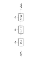
- FIG. 1 is a schematic configuration diagram of a motor control system 1 in the present embodiment.
- a motor control system 1 controls driving of a three-phase motor 3 serving as a driving source of a cooling fan for a heat exchanger (radiator) mounted on a vehicle.
- the motor control system 1 includes a three-phase motor 3 and an inverter system (cooling fan motor-inverter system for vehicle) 2.
- the inverter system 2 includes a motor control device 21 having a switching element 22, a measurement unit (measurement means) 23, a first control unit (first control means) 24, and an insulation unit (insulation means) 8. .
- the motor control device 21 converts a direct current supplied from a high voltage power source 4 such as a high voltage battery or a generator into a three phase alternating current to drive the three phase motor 3.
- the high voltage power supply 4 is, for example, a voltage of 200 [V] or 400 [V], and supplies power to the motor control device 21 through the HV filter 26.
- the switching element 22 is a power transistor formed of a semiconductor element, and, for example, a MOSFET, a bipolar transistor, an IGBT or the like is used.
- a semiconductor material a Si-based semiconductor or a SiC-based semiconductor is used.
- the low voltage power supply 5 is an onboard battery power supply or the like, and supplies, for example, a voltage of 12 [V].
- the motor control system 1 is connected to a vehicle network CAN (Controller Area Network) 7 which is a vehicle network as a communication form with the vehicle side.
- vehicle network CAN Controller Area Network
- the inverter system 2 is provided with an isolated CAN driver (communication control means) 82 constituting a control communication circuit, and a host vehicle-side ECU (Electric Control Unit) (second
- the communication cable from the control means 6 is configured to be connectable.
- the vehicle network is described using CAN as an example.
- the present invention is not limited to this.
- other systems such as LIN (Local Interconnect Network) and FlexRay are used. It may be present and is not particularly limited.
- the insulating unit 8 electrically insulates the low voltage system 9 to which power is supplied from the low voltage power supply 5 and the high voltage system 10 to which power is supplied from the high voltage power supply 4. In addition, the insulating unit 8 operates by the power supplied from the low voltage power supply 5. Specifically, the insulating unit 8 is an isolated DC-DC converter 81, an isolated CAN driver 82, and an isolated PWM driver (PWM control means) And 83.
- the isolated DC-DC converter 81 supplies the power of the low voltage power supply 5 to the motor control device 21 and the first control unit 24.
- the insulation type DC-DC converter 81 is used as a drive voltage (for example, 5 [V]) of the first control unit 24 and a drive voltage (for example, 15 [V]) of the motor control device 21.
- the isolated CAN driver 82 is connected to the vehicle network CAN 7, is connected to the vehicle ECU 6 via the vehicle network CAN 7, and exchanges information between the vehicle ECU 6 and the first control unit 24.
- the isolated PWM driver 83 is operated by the power supplied from the low voltage power supply 5, performs PWM control in response to the duty, and controls the switching element 22 of the motor control device 21.
- the isolated PWM driver 83 is configured to include a photocoupler 83a, an inverter 83b, and a low pass filter 83c.
- the PWM command is input to the photocoupler 83a, an analog value of 0 to 5 [V] indicating a duty is converted and output to the first control unit 24 as a rotation speed command.
- the first control unit 24 controls the motor control device 21. Specifically, the first control unit 24 acquires the rotational speed instruction of the three-phase motor 3 via at least one of the isolated PWM driver 83 and the isolated CAN driver 82, and acquires the acquired rotational speed instruction. Control the three-phase motor 3 based on The first control unit 24 includes a determination unit 25.
- the determination unit 25 determines the presence or absence of abnormality of the switching element 22 based on at least one of the temperature value, the current value, and the voltage value acquired from the measurement unit 23. Specifically, the determination unit 25 has a threshold value related to the temperature value, the current value, and the voltage value, and determines an abnormality when exceeding a predetermined threshold value, and determines the determination result as a vehicle via the vehicle network CAN7. Output to the side ECU 6 In addition, when an abnormality is detected in the switching element 22, the first control unit 24 notifies the vehicle-side ECU 6 that there is an abnormality in the switching element 22 via the isolated CAN driver 82. Output to the side
- the measuring unit 23 measures at least one of the temperature value, the current value, and the voltage value of the switching element 22 of the motor control device 21, and outputs the measured value to the first control unit 24. For example, when the three-phase motor 3 or the switching element 22 of the motor control device 21 is broken, the temperature of the switching element 22 becomes high, so the measuring unit 23 detects a temperature change of the switching element 22 to perform the first control. The unit 24 determines whether there is a failure.
- the direct current power supplied from the high voltage power supply 4 mounted on the vehicle to the motor control device 21 is converted into a three-phase alternating current and supplied to the three-phase motor 3 to drive the three-phase motor 3.
- the rotational speed instruction of the three-phase motor 3 acquired from the vehicle side ECU 6 provided on the vehicle side via the isolated CAN driver 82 or the rotational speed instruction for PWM control acquired via the isolated PWM driver 83 Based on this, the inverter system 2 is controlled. Thereby, the three-phase motor 3 is rotationally driven, and the radiator cooling fan operates.
- the temperature value, current value, and voltage value of the switching element 22 are measured, and the measurement result is output to the first control unit 24. Then, the determination result of the first control unit 24 compares the measurement result with a predetermined threshold value, and when it exceeds the predetermined threshold value, the abnormality information is sent to the vehicle-side ECU 6 via the vehicle network CAN7. Be notified.
- abnormality information is acquired from the inverter system 2 via the vehicle network CAN 7 in the vehicle side ECU 6 which is a control circuit on the vehicle side, occurrence of an abnormality in the radiator cooling fan is detected. By presenting that the abnormality has occurred in the cooling fan for the radiator via the presentation unit (not shown) or the like, the driver of the vehicle can grasp the abnormality.
- the abnormality information is transmitted to the vehicle via the isolated CAN driver 82. Since the notification is made, the vehicle side can detect an abnormality in the three-phase motor 3 that drives the cooling fan, which can be useful for investigating the cause of the abnormality. In addition, by using the three-phase motor 3 for driving the cooling fan, low loss and high efficiency driving can be achieved. Further, power is supplied from a high voltage power supply (for example, 200 to 400 [V]) 4 to drive the three-phase motor 3.
- a high voltage power supply for example, 200 to 400 [V]
- the low voltage power supply 5 which is a battery having a small battery capacity (for example, 12 V) of the vehicle. No need to worry about battery consumption.
- Motor control system Inverter system (cooling fan motor and inverter system for vehicles) 3 Three-phase motor 6 Vehicle-side ECU (second control means) 7 Vehicle Network CAN 8 Insulation (insulation means) 21 motor controller 22 switching element 23 measuring unit (measuring means) 24 First control unit (first control means) 81 Isolated DC-DC converter 82 Isolated CAN driver (communication control means) 83 Isolated PWM Driver (PWM Control Means)
Abstract
Description
モータ回転数は、車速、エンジン冷却水温、AC圧力に基づき速度制御される。エアコンがオン状態の場合は、エアコンの圧力信号と車両側から受けた車速信号とに基づき、エアコンECUで必要ファン制御を演算し、車両用ECUに出力する。車両用ECUはその信号に、さらに車速とエンジン冷却水温とを加味してファンモータの回転数を決定し、ファン駆動用PWM信号を出力する。一方、エアコンがオフ状態の場合は、車速とエンジン冷却水温とに基づき車両用ECUでファン回転数を決定し、ファン駆動用PWM信号を出力する。 Conventionally, a fan control device for controlling a cooling fan of an on-vehicle heat exchanger is disposed under a vehicle ECU (Electronic Control Unit), and the cooling fan control is performed by PWM (pulse width) output from the vehicle ECU Motor rotational speed control is performed according to the duty ratio of the modulation signal.
The motor rotational speed is controlled based on the vehicle speed, the engine coolant temperature, and the AC pressure. When the air conditioner is in the on state, the air conditioner ECU calculates necessary fan control based on the pressure signal of the air conditioner and the vehicle speed signal received from the vehicle side, and outputs it to the vehicle ECU. The vehicle ECU further adds the vehicle speed and the engine coolant temperature to the signal to determine the rotational speed of the fan motor, and outputs a fan drive PWM signal. On the other hand, when the air conditioner is off, the vehicle ECU determines the fan rotational speed based on the vehicle speed and the engine coolant temperature, and outputs a fan drive PWM signal.
このように、モータ制御装置に異常が検出された場合には、通信制御手段を介して異常情報を車両側に通知するので、車両側でクーリングファンを駆動する三相モータの異常を検出でき、その異常の原因究明に役立てることができる。また、クーリングファンの駆動に三相モータを用いることにより、低損失、高効率駆動が可能となる。また、三相モータの駆動には高電圧電源(例えば、200~400〔V〕)から電力が供給されるので、車両の有する電池容量の小さいバッテリ(例えば、12〔V〕)である低電圧電源から電力供給する場合と比較して、バッテリの消費量を気にする必要がなくなる。
ここで、スイッチング素子は、半導体素子で構成されるパワートランジスタであり、例えば、MOSFET(Metal-Oxide-Semiconductor Field-Effect Transistor)、バイポーラトランジスタ、及びIGBT(Insulated Gate Bipolar Transistor)等が使用される。また、半導体材料としては、Si(シリコン)系半導体やSiC(炭化珪素)系半導体が用いられる。 According to this configuration, the motor control device having the switching element, which converts the DC power supplied from the high voltage power source into the three-phase AC power and supplies the power to the three-phase motor is controlled by the first control means. When an abnormality is detected in the switching element of the motor control device, the communication control means is connected to the second control means connected to the second vehicle control means on the upper side of the cooling fan motor / inverter system for the vehicle. The first control means notifies that the switching element has an abnormality. In addition, by electrically insulating the low voltage system and the high voltage system, the safety of the passenger (on board the vehicle) against the high voltage is secured.
As described above, when an abnormality is detected in the motor control device, the abnormality information is notified to the vehicle side via the communication control means, so that the abnormality of the three-phase motor driving the cooling fan can be detected on the vehicle side, It can be used to investigate the cause of the abnormality. In addition, by using a three-phase motor for driving the cooling fan, low loss and high efficiency driving can be achieved. In addition, since power is supplied from a high voltage power supply (for example, 200 to 400 V) to drive the three-phase motor, a low voltage that is a battery (for example, 12 V) having a small battery capacity of the vehicle There is no need to worry about battery consumption as compared to the case where power is supplied from a power supply.
Here, the switching element is a power transistor composed of a semiconductor element, and, for example, a MOSFET (Metal-Oxide-Semiconductor Field-Effect Transistor), a bipolar transistor, an IGBT (Insulated Gate Bipolar Transistor) or the like is used. In addition, as a semiconductor material, a Si (silicon) based semiconductor or a SiC (silicon carbide) based semiconductor is used.
図1は、本実施形態におけるモータ制御システム1の概略構成図である。
図1に示されるように、本実施形態に係るモータ制御システム1は、車載の熱交換器(ラジエータ)用のクーリングファンの駆動源となる三相モータ3の駆動を制御するものである。 In the present embodiment, a case where the vehicle cooling fan motor / inverter system is applied to a three-phase motor for driving a cooling fan that supplies air to a vehicle-mounted heat exchanger will be described as an example.
FIG. 1 is a schematic configuration diagram of a motor control system 1 in the present embodiment.
As shown in FIG. 1, a motor control system 1 according to the present embodiment controls driving of a three-
インバータシステム2は、スイッチング素子22を有するモータ制御装置21と、計測部(計測手段)23と、第1制御部(第1制御手段)24と、絶縁部(絶縁手段)8とを備えている。モータ制御装置21は、高電圧バッテリや発電機等の高電圧電源4から供給される直流電流を三相の交流電流に変換し、三相モータ3を駆動する。高電圧電源4は、例えば、200〔V〕や400〔V〕の電圧であり、HVフィルタ26を介してモータ制御装置21に電力供給している。
ここで、スイッチング素子22は、半導体素子で構成されるパワートランジスタであり、例えば、MOSFET、バイポーラトランジスタ、及びIGBT等が使用される。また、半導体材料としては、Si系半導体やSiC系半導体が用いられる。 The motor control system 1 includes a three-
The
Here, the
モータ制御システム1は、車両側との通信フォームとして車両ネットワークである車両ネットワークCAN(Controller Area Network)7と接続されている。このため、インバータシステム2は、制御通信回路を構成する絶縁型CANドライバ(通信制御手段)82が設けられており、車両側に設けられている上位の車両側ECU(Electric Control Unit)(第2制御手段)6からの通信ケーブルが接続可能に構成されている。
なお、本実施形態においては、車両ネットワークにCANを利用するものであることを例に挙げて説明するがこれに限定されず、例えば、LIN(Local Interconnect Network)や、FlexRay等の他の方式であってもよく、特に限定されない。 The low
The motor control system 1 is connected to a vehicle network CAN (Controller Area Network) 7 which is a vehicle network as a communication form with the vehicle side. For this reason, the
In the present embodiment, the vehicle network is described using CAN as an example. However, the present invention is not limited to this. For example, other systems such as LIN (Local Interconnect Network) and FlexRay are used. It may be present and is not particularly limited.
絶縁型CANドライバ82は、車両ネットワークCAN7と接続されており、車両ネットワークCAN7を介して車両側ECU6に接続され、車両側ECU6と第1制御部24との間で情報を授受する。
絶縁型PWMドライバ83は、低電圧電源5から供給される電力によって作動し、デューティに応答してPWM制御を行って、モータ制御装置21のスイッチング素子22を制御する。図2には、絶縁型PWMドライバ83の一例が示されている。図2に示されるように、絶縁型PWMドライバ83は、フォトカプラ83a、インバータ83b、及びローパスフィルタ83cを備えて構成されている。フォトカプラ83aにPWMコマンドが入力されると、デューティを示す0から5〔V〕のアナログ値が変換され、第1制御部24に回転数指令として出力される。 The isolated DC-
The
The
第1制御部24は、判定部25を備えている。判定部25は、計測部23から取得した温度値、電流値、及び電圧値のうち少なくともいずれか一に基づいて、スイッチング素子22の異常有無を判定する。具体的には、判定部25は、温度値、電流値、及び電圧値に関する閾値を有しており、所定の閾値を超過した場合に異常と判定し、車両ネットワークCAN7を介して判定結果を車両側ECU6に出力する。
また、第1制御部24は、スイッチング素子22に異常が検出された場合に、絶縁型CANドライバ82を介して、車両側ECU6に対して、スイッチング素子22に異常がある旨を通知する異常情報を出力する。 The
The
In addition, when an abnormality is detected in the switching
車両に搭載される高電圧電源4からモータ制御装置21に供給された直流電力は、三相の交流電流に変換され、三相モータ3に給電されて三相モータ3を駆動させる。絶縁型CANドライバ82を介して車両側に設けられている車両側ECU6から取得される三相モータ3の回転数指示、または絶縁型PWMドライバ83を介して取得されるPWM制御する回転数指示に基づいて、インバータシステム2が制御される。
これにより、三相モータ3が回転駆動され、ラジエータ用クーリングファンが作動する。 Next, the operation of the motor control system 1 according to the present embodiment will be described.
The direct current power supplied from the high
Thereby, the three-
車両側の制御回路である車両側ECU6において、車両ネットワークCAN7を介してインバータシステム2から異常情報が取得されると、ラジエータ用クーリングファンにおいて異常が発生したことが検出される。提示部(図示略)等を介してラジエータ用クーリングファンに異常が発生したことが提示されることにより、車両の運転者によって異常を把握させることができる。 The temperature value, current value, and voltage value of the switching
When abnormality information is acquired from the
2 インバータシステム(車両用クーリングファンモータ・インバータシステム)
3 三相モータ
6 車両側ECU(第2制御手段)
7 車両ネットワークCAN
8 絶縁部(絶縁手段)
21 モータ制御装置
22 スイッチング素子
23 計測部(計測手段)
24 第1制御部(第1制御手段)
81 絶縁型DC-DCコンバータ
82 絶縁型CANドライバ(通信制御手段)
83 絶縁型PWMドライバ(PWM制御手段) 1
3 Three-
7 Vehicle Network CAN
8 Insulation (insulation means)
21
24 First control unit (first control means)
81 Isolated DC-
83 Isolated PWM Driver (PWM Control Means)
Claims (5)
- 車載の熱交換器に空気を供給するクーリングファンを駆動する三相モータを制御する車両用クーリングファンモータ・インバータシステムであって、
スイッチング素子を有し、高電圧電源から供給される直流電力を三相交流電力に変換し、前記三相モータに電力供給するモータ制御装置と、
前記モータ制御装置を制御する第1制御手段と、
低電圧電源から供給される電力によって作動し、当該車両用クーリングファンモータ・インバータシステムの上位の車両側の第2制御手段と情報を授受する通信制御手段と、
前記低電圧電源から電力が供給される低電圧系統と、前記高電圧電源から電力が供給される高電圧系統とを電気的に絶縁させる絶縁手段と、
を具備し、
前記第1制御手段は、前記スイッチング素子に異常が検出された場合に、前記通信制御手段を介して、前記第2制御手段に対して、前記三相モータの制御に異常がある旨を通知する異常情報を出力する車両用クーリングファンモータ・インバータシステム。 A cooling fan motor / inverter system for a vehicle that controls a three-phase motor driving a cooling fan that supplies air to a vehicle-mounted heat exchanger, comprising:
A motor control device having a switching element, which converts DC power supplied from a high voltage power supply into three-phase AC power and supplies the power to the three-phase motor;
First control means for controlling the motor control device;
Communication control means which is operated by the electric power supplied from the low voltage power source and exchanges information with the second control means on the vehicle side higher than the vehicle cooling fan motor-inverter system;
An insulation means for electrically insulating a low voltage system to which power is supplied from the low voltage power supply and a high voltage system to which power is supplied from the high voltage power supply;
Equipped with
The first control means notifies the second control means that there is an abnormality in the control of the three-phase motor via the communication control means when an abnormality is detected in the switching element. Cooling fan motor / inverter system for vehicles that outputs error information. - 前記低電圧電源から供給される電力によって作動し、デューティに応答してPWM(pulse width modulation)制御を行って、前記モータ制御装置の前記スイッチング素子を制御するPWM制御手段を具備し、
前記第1制御手段は、前記PWM制御手段及び前記通信制御手段のうち少なくともどちらか一方を介して、前記三相モータの回転数指示を取得する請求項1に記載の車両用クーリングファンモータ・インバータシステム。 The motor control apparatus comprises PWM control means which operates by power supplied from the low voltage power supply, performs PWM (pulse width modulation) control in response to a duty, and controls the switching element of the motor control device.
The vehicle cooling fan motor / inverter according to claim 1, wherein said first control means acquires a rotation speed instruction of said three-phase motor via at least one of said PWM control means and said communication control means. system. - 前記モータ制御装置の前記スイッチング素子の温度値、電流値、及び電圧値のうち少なくともいずれか一を計測し、出力する計測手段を具備し、
前記第1制御手段は、前記計測手段から取得した前記温度値、電流値、及び電圧値のうち少なくともいずれか一に基づいて、前記スイッチング素子の異常有無を判定する判定手段を具備する請求項1または請求項2に記載の車両用クーリングファンモータ・インバータシステム。 The motor control device further includes a measuring unit that measures and outputs at least one of a temperature value, a current value, and a voltage value of the switching element of the motor control device.
The first control means comprises determination means for determining the presence or absence of abnormality of the switching element based on at least one of the temperature value, current value, and voltage value acquired from the measurement means. The vehicle cooling fan motor / inverter system according to claim 2 or 3. - 車載の熱交換器に空気を供給するクーリングファンを駆動する三相モータを制御する車両用クーリングファンモータ・インバータシステムの制御方法であって、
前記車両用クーリングファンモータ・インバータシステムは、スイッチング素子を有し、高電圧電源から供給される直流電力を三相交流電力に変換し、前記三相モータに電力供給するモータ制御装置と、前記モータ制御装置を制御する第1制御手段と、低電圧電源から供給される電力によって作動し、当該車両用クーリングファンモータ・インバータシステムの上位の車両側の第2制御手段と情報を授受する通信制御手段と、前記低電圧電源から電力が供給される低電圧系統と、前記高電圧電源から電力が供給される高電圧系統とを電気的に絶縁させる絶縁手段と、を具備する場合に、
前記スイッチング素子に異常が検出された場合に、前記通信制御手段を介して、前記第2制御手段に対して、前記三相モータの制御に異常がある旨を通知する異常情報を出力する車両用クーリングファンモータ・インバータシステムの制御方法。 A control method of a cooling fan motor / inverter system for a vehicle for controlling a three-phase motor driving a cooling fan for supplying air to a heat exchanger mounted on a vehicle, comprising:
The vehicle cooling fan motor-inverter system has a switching element, converts DC power supplied from a high voltage power source into three-phase AC power, and supplies the three-phase motor with the motor control device, and the motor Communication control means that operates with the first control means for controlling the control device and the power supplied from the low voltage power supply, and exchanges information with the second control means on the vehicle side above the cooling fan motor / inverter system for the vehicle And a low voltage system to which power is supplied from the low voltage power supply, and an insulating means for electrically insulating the high voltage system to which power is supplied from the high voltage power supply,
For vehicles that output abnormality information notifying that there is an abnormality in the control of the three-phase motor to the second control means via the communication control means when an abnormality is detected in the switching element Control method of cooling fan motor and inverter system. - 車載の熱交換器に空気を供給するクーリングファンを駆動する三相モータを制御する車両用クーリングファンモータ・インバータシステムの制御プログラムであって、
前記車両用クーリングファンモータ・インバータシステムは、スイッチング素子を有し、高電圧電源から供給される直流電力を三相交流電力に変換し、前記三相モータに電力供給するモータ制御装置と、前記モータ制御装置を制御する第1制御手段と、低電圧電源から供給される電力によって作動し、当該車両用クーリングファンモータ・インバータシステムの上位の車両側の第2制御手段と情報を授受する通信制御手段と、前記低電圧電源から電力が供給される低電圧系統と、前記高電圧電源から電力が供給される高電圧系統とを電気的に絶縁させる絶縁手段と、を具備する場合に、
前記スイッチング素子に異常が検出された場合に、前記通信制御手段を介して、前記第2制御手段に対して、前記三相モータの制御に異常がある旨を通知する異常情報を出力する車両用クーリングファンモータ・インバータシステムの制御プログラム。 A control program for a cooling fan motor / inverter system for a vehicle that controls a three-phase motor driving a cooling fan that supplies air to an on-vehicle heat exchanger, the control program comprising:
The vehicle cooling fan motor-inverter system has a switching element, converts DC power supplied from a high voltage power source into three-phase AC power, and supplies the three-phase motor with the motor control device, and the motor Communication control means that operates with the first control means for controlling the control device and the power supplied from the low voltage power supply, and exchanges information with the second control means on the vehicle side above the cooling fan motor / inverter system for the vehicle And a low voltage system to which power is supplied from the low voltage power supply, and an insulating means for electrically insulating the high voltage system to which power is supplied from the high voltage power supply,
For vehicles that output abnormality information notifying that there is an abnormality in the control of the three-phase motor to the second control means via the communication control means when an abnormality is detected in the switching element Control program for cooling fan motor and inverter system.
Priority Applications (3)
| Application Number | Priority Date | Filing Date | Title |
|---|---|---|---|
| US14/764,891 US10050577B2 (en) | 2013-02-22 | 2013-08-29 | Vehicle cooling-fan motor/inverter system, control method therefor, and program therefor |
| DE112013006719.6T DE112013006719B4 (en) | 2013-02-22 | 2013-08-29 | Vehicle cooling fan motor / inverter system with fault detection of the electrical control of the motor, control method and program for it |
| CN201380073185.2A CN105074156B (en) | 2013-02-22 | 2013-08-29 | The inverter system and its control method and system of vehicle motor for cooling fan |
Applications Claiming Priority (2)
| Application Number | Priority Date | Filing Date | Title |
|---|---|---|---|
| JP2013-033581 | 2013-02-22 | ||
| JP2013033581A JP6012506B2 (en) | 2013-02-22 | 2013-02-22 | Cooling fan motor / inverter system for vehicle, control method and program thereof |
Publications (1)
| Publication Number | Publication Date |
|---|---|
| WO2014128997A1 true WO2014128997A1 (en) | 2014-08-28 |
Family
ID=51390815
Family Applications (1)
| Application Number | Title | Priority Date | Filing Date |
|---|---|---|---|
| PCT/JP2013/073079 WO2014128997A1 (en) | 2013-02-22 | 2013-08-29 | Cooling fan motor/inverter system for vehicles and control method and program therefor |
Country Status (5)
| Country | Link |
|---|---|
| US (1) | US10050577B2 (en) |
| JP (1) | JP6012506B2 (en) |
| CN (1) | CN105074156B (en) |
| DE (1) | DE112013006719B4 (en) |
| WO (1) | WO2014128997A1 (en) |
Cited By (1)
| Publication number | Priority date | Publication date | Assignee | Title |
|---|---|---|---|---|
| JP2017056912A (en) * | 2015-09-18 | 2017-03-23 | 株式会社デンソー | Control module for vehicle |
Families Citing this family (7)
| Publication number | Priority date | Publication date | Assignee | Title |
|---|---|---|---|---|
| JP6558854B2 (en) * | 2016-02-04 | 2019-08-14 | 株式会社ミツバ | Cooling fan control device |
| KR101886104B1 (en) * | 2016-10-26 | 2018-08-07 | 현대자동차 주식회사 | Control apparatus and method for cooling fan of vehicle |
| CN108930654A (en) * | 2018-09-06 | 2018-12-04 | 天台华鑫电器有限公司 | A kind of DC electronic water pump |
| CN110103715A (en) * | 2019-06-04 | 2019-08-09 | 上海华羿汽车系统集成有限公司 | A kind of electric commercial vehicle and method for controlling power supply |
| US11376922B2 (en) * | 2019-09-09 | 2022-07-05 | Thermo King Corporation | Transport climate control system with a self-configuring matrix power converter |
| CN113131440B (en) * | 2019-12-31 | 2022-09-06 | 比亚迪股份有限公司 | Motor control system and motor control device |
| JP2023172653A (en) * | 2022-05-24 | 2023-12-06 | 三菱重工サーマルシステムズ株式会社 | Operation recording system, vehicle, operation recording method, and operation recording program |
Citations (2)
| Publication number | Priority date | Publication date | Assignee | Title |
|---|---|---|---|---|
| JP2005069160A (en) * | 2003-08-27 | 2005-03-17 | Calsonic Kansei Corp | Motor-driven fan control device |
| JP2006182114A (en) * | 2004-12-27 | 2006-07-13 | Denso Corp | Vehicular electric fan system |
Family Cites Families (18)
| Publication number | Priority date | Publication date | Assignee | Title |
|---|---|---|---|---|
| US4667480A (en) * | 1986-09-22 | 1987-05-26 | General Electric Company | Method and apparatus for controlling an electrically driven automotive air conditioner |
| US5825972A (en) * | 1995-02-17 | 1998-10-20 | Dell Usa, L.P. | Direct current fan motor speed controller |
| JP3351330B2 (en) * | 1997-12-26 | 2002-11-25 | 松下電器産業株式会社 | Inverter system for air conditioning |
| JP2001020741A (en) | 1999-07-01 | 2001-01-23 | Denyo Co Ltd | Cooling device for radiator in engine-driven work machine |
| JP2002199773A (en) * | 2000-12-27 | 2002-07-12 | Sanden Corp | Drive control method for compressor motor and inverter for driving compressor |
| JP2005299407A (en) | 2004-04-07 | 2005-10-27 | Toyota Motor Corp | Cooling system, method for controlling the same, and automobile |
| JP2006042446A (en) * | 2004-07-23 | 2006-02-09 | Yamaha Motor Co Ltd | Abnormality-monitoring apparatus for motor control system |
| JP2006050779A (en) * | 2004-08-04 | 2006-02-16 | Toyota Motor Corp | Motor driving device |
| DE102005057989A1 (en) | 2004-12-06 | 2006-06-14 | Denso Corp., Kariya | Electric fan system for a vehicle |
| JP2007137299A (en) * | 2005-11-21 | 2007-06-07 | Toyota Motor Corp | Power supply control device |
| JP4839109B2 (en) | 2006-03-17 | 2011-12-21 | 株式会社オートネットワーク技術研究所 | In-vehicle database system |
| JP5095955B2 (en) * | 2006-05-11 | 2012-12-12 | トヨタ自動車株式会社 | Vehicle and control method thereof |
| JP4939355B2 (en) * | 2007-09-28 | 2012-05-23 | 三菱重工業株式会社 | Inverter system for automotive air conditioners |
| JP5473212B2 (en) | 2007-12-06 | 2014-04-16 | 三菱重工業株式会社 | Inverter system for in-vehicle air conditioner |
| DE112009000439T8 (en) | 2008-02-29 | 2012-01-19 | Autonetworks Technologies, Ltd. | A vehicle information recording device, a vehicle information communication system, and a vehicle information communication method |
| JP5130142B2 (en) | 2008-07-25 | 2013-01-30 | 本田技研工業株式会社 | Inverter generator |
| JP4947045B2 (en) * | 2008-12-19 | 2012-06-06 | トヨタ自動車株式会社 | Cooling device and vehicle equipped with the same |
| IT1404232B1 (en) | 2010-12-16 | 2013-11-15 | Gate Srl | ROTATION SPEED CONTROL SYSTEM OF AN ELECTRIC FAN ASSOCIATED WITH HEAT EXCHANGERS OF A MOTOR VEHICLE |
-
2013
- 2013-02-22 JP JP2013033581A patent/JP6012506B2/en not_active Expired - Fee Related
- 2013-08-29 WO PCT/JP2013/073079 patent/WO2014128997A1/en active Application Filing
- 2013-08-29 DE DE112013006719.6T patent/DE112013006719B4/en not_active Expired - Fee Related
- 2013-08-29 US US14/764,891 patent/US10050577B2/en not_active Expired - Fee Related
- 2013-08-29 CN CN201380073185.2A patent/CN105074156B/en not_active Expired - Fee Related
Patent Citations (2)
| Publication number | Priority date | Publication date | Assignee | Title |
|---|---|---|---|---|
| JP2005069160A (en) * | 2003-08-27 | 2005-03-17 | Calsonic Kansei Corp | Motor-driven fan control device |
| JP2006182114A (en) * | 2004-12-27 | 2006-07-13 | Denso Corp | Vehicular electric fan system |
Cited By (1)
| Publication number | Priority date | Publication date | Assignee | Title |
|---|---|---|---|---|
| JP2017056912A (en) * | 2015-09-18 | 2017-03-23 | 株式会社デンソー | Control module for vehicle |
Also Published As
| Publication number | Publication date |
|---|---|
| JP2014162307A (en) | 2014-09-08 |
| DE112013006719B4 (en) | 2019-10-24 |
| US20150365039A1 (en) | 2015-12-17 |
| US10050577B2 (en) | 2018-08-14 |
| CN105074156A (en) | 2015-11-18 |
| CN105074156B (en) | 2018-06-01 |
| DE112013006719T5 (en) | 2015-11-12 |
| JP6012506B2 (en) | 2016-10-25 |
Similar Documents
| Publication | Publication Date | Title |
|---|---|---|
| WO2014128997A1 (en) | Cooling fan motor/inverter system for vehicles and control method and program therefor | |
| US10110154B2 (en) | Controller and a method to drive an inverter circuit for a permanent-magnet synchronous motor | |
| EP2164162B1 (en) | Electric compressor control device | |
| US9667169B2 (en) | Power conversion apparatus | |
| US10044297B2 (en) | Method and apparatus for controlling an electric motor of a cooling fan | |
| KR101592780B1 (en) | Method for detecting connector interlock in eco-friendly vehicle | |
| JP6252244B2 (en) | Motor drive device | |
| US7977900B2 (en) | Inverter system for vehicle-mounted air conditioner | |
| JP6259975B2 (en) | Overvoltage protection measures for active rectifiers during load shedding | |
| JP2004336907A (en) | Inverter system | |
| EP2189733B1 (en) | Heater Controller and method for operating a heater controller | |
| JP7061060B2 (en) | Control circuit, drive system and inverter control method | |
| JP5473212B2 (en) | Inverter system for in-vehicle air conditioner | |
| JP2010093934A (en) | Vehicle-mounted apparatus | |
| US9421847B2 (en) | Vehicle-cooling-fan control system and control method therefor | |
| JP5111208B2 (en) | Power converter | |
| JP2003009312A (en) | Control device for electric vehicle | |
| JP2013255297A (en) | Vehicular inverter device | |
| KR100384171B1 (en) | Device and method for driving a motor of electric vehicle in a state of emergency | |
| JP7174657B2 (en) | Abnormality detection device for power conversion circuit | |
| CN112937301A (en) | Dissipation circuit for electric vehicle | |
| CN115395813A (en) | Inverter device | |
| JP2020150744A (en) | Power control unit | |
| JP2010136502A (en) | Controller of electric motor and vehicle | |
| JPH07336801A (en) | Control and driving apparatus for car |
Legal Events
| Date | Code | Title | Description |
|---|---|---|---|
| WWE | Wipo information: entry into national phase |
Ref document number: 201380073185.2 Country of ref document: CN |
|
| 121 | Ep: the epo has been informed by wipo that ep was designated in this application |
Ref document number: 13875470 Country of ref document: EP Kind code of ref document: A1 |
|
| WWE | Wipo information: entry into national phase |
Ref document number: 14764891 Country of ref document: US |
|
| WWE | Wipo information: entry into national phase |
Ref document number: 1120130067196 Country of ref document: DE Ref document number: 112013006719 Country of ref document: DE |
|
| 122 | Ep: pct application non-entry in european phase |
Ref document number: 13875470 Country of ref document: EP Kind code of ref document: A1 |