WO2014128938A1 - Permanent magnet embedded motor, compressor, and refrigeration air conditioner - Google Patents
Permanent magnet embedded motor, compressor, and refrigeration air conditioner Download PDFInfo
- Publication number
- WO2014128938A1 WO2014128938A1 PCT/JP2013/054610 JP2013054610W WO2014128938A1 WO 2014128938 A1 WO2014128938 A1 WO 2014128938A1 JP 2013054610 W JP2013054610 W JP 2013054610W WO 2014128938 A1 WO2014128938 A1 WO 2014128938A1
- Authority
- WO
- WIPO (PCT)
- Prior art keywords
- stator core
- permanent magnet
- electric motor
- frame
- motor according
- Prior art date
Links
Images


Classifications
-
- H—ELECTRICITY
- H02—GENERATION; CONVERSION OR DISTRIBUTION OF ELECTRIC POWER
- H02K—DYNAMO-ELECTRIC MACHINES
- H02K1/00—Details of the magnetic circuit
- H02K1/06—Details of the magnetic circuit characterised by the shape, form or construction
- H02K1/12—Stationary parts of the magnetic circuit
- H02K1/14—Stator cores with salient poles
- H02K1/146—Stator cores with salient poles consisting of a generally annular yoke with salient poles
- H02K1/148—Sectional cores
-
- H—ELECTRICITY
- H02—GENERATION; CONVERSION OR DISTRIBUTION OF ELECTRIC POWER
- H02K—DYNAMO-ELECTRIC MACHINES
- H02K1/00—Details of the magnetic circuit
- H02K1/06—Details of the magnetic circuit characterised by the shape, form or construction
- H02K1/12—Stationary parts of the magnetic circuit
- H02K1/18—Means for mounting or fastening magnetic stationary parts on to, or to, the stator structures
- H02K1/185—Means for mounting or fastening magnetic stationary parts on to, or to, the stator structures to outer stators
-
- H—ELECTRICITY
- H02—GENERATION; CONVERSION OR DISTRIBUTION OF ELECTRIC POWER
- H02K—DYNAMO-ELECTRIC MACHINES
- H02K2213/00—Specific aspects, not otherwise provided for and not covered by codes H02K2201/00 - H02K2211/00
- H02K2213/03—Machines characterised by numerical values, ranges, mathematical expressions or similar information
Definitions
- the present invention relates to a permanent magnet embedded electric motor, a compressor, and a refrigeration air conditioner.
- An embedded permanent magnet electric motor is used as an electric motor for driving a compressor.
- the stator core (stator core) of an electric motor is often fixed to the inner peripheral portion of a cylindrical airtight container (frame) by shrink fitting. That is, a frame having an inner diameter slightly smaller than the outer diameter of the stator core is manufactured, and this frame is heated and thermally expanded so that the inner diameter of the frame is larger than the outer diameter of the stator core. And after inserting a stator core in an inner diameter part of a frame, it cools to normal temperature. As a result, the inner diameter of the frame is reduced, and the stator core is held on the frame by the tightening force of the frame.
- stator core When the stator core is fixed to the frame by shrink fitting, a pressing force directed from the inner peripheral surface (frame inner peripheral portion) of the frame toward the axial center acts on the outer peripheral surface (stator outer peripheral portion) of the stator core.
- the aforementioned pressing force is applied to the entire periphery of the stator outer periphery, and substantially the entire region in the circumferential direction of the stator outer periphery is subjected to compressive stress. receive.
- the magnetic permeability of the electromagnetic steel sheet constituting the stator core is reduced, the amount of magnetic flux flowing through the electromagnetic steel sheet (that is, the stator core) is reduced, and the torque of the electric motor is reduced.
- the iron loss density of the electromagnetic steel sheet increases, the iron loss at the time of driving the motor increases, and the efficiency of the motor decreases.
- a contact surface between the stator outer peripheral portion and the frame inner peripheral portion, and the stator outer peripheral portion and the frame are disposed between the stator outer peripheral portion and the frame inner peripheral portion.
- a gap (non-contact surface) between the inner peripheral portion and the inner peripheral portion is formed, and the center angle of the contact surface is set within a range of 130 degrees.
- the axial length of the inner periphery of the frame is formed smaller than the axial length of the stator core. Furthermore, this prior art has a fitting part formed so that the inner diameter dimension of the frame is smaller than the outer diameter dimension of the stator core. And the part facing the fitting part of the stator outer peripheral part is fitted with this fitting part, and the part other than the part facing the fitting part of the stator outer peripheral part (non-opposing part of the stator outer peripheral part) A gap is formed, and a part of the outer periphery of the stator is held on the frame by stator holding means (such as arc spot welding).
- stator holding means such as arc spot welding
- the present invention has been made in view of the above, and provides a highly reliable embedded permanent magnet electric motor, a compressor, and a refrigeration air conditioner while ensuring a removal load of a stator core composed of split cores.
- the purpose is to obtain.
- the present invention provides a stator core in which three or more divided cores arranged at equal central angles are arranged in an annular shape, and the stator core
- a permanent magnet embedded type electric motor including a rotor disposed on an inner diameter portion of the rotor and a frame containing the split cores, and an outer peripheral portion of each split core includes a center of the stator core and the split cores.
- a plurality of projecting protrusions are formed from the outer peripheral portion toward the inner peripheral portion of the frame at a position symmetrical in the circumferential direction with respect to the central axis connecting the center of the core, and a divisor of the total number of divided cores n (n is an integer of 3 or more) divided by 360, and the outer periphery of the split core provided at equal intervals in the circumferential direction at a central angle is a position other than the position where the protrusion is formed, and Front from the inner periphery at a position symmetrical in the circumferential direction with respect to the central axis A plurality of recess reces shaped as a collision in the direction of the outer peripheral portion is formed, characterized by.
- FIG. 1 is a longitudinal sectional view of a compressor provided with a permanent magnet embedded electric motor according to an embodiment of the present invention.
- 2 is a cross-sectional view taken along arrow AA shown in FIG.
- FIG. 3 is a detailed view of a main part of the permanent magnet embedded motor shown in FIG.
- FIG. 4 is a cross-sectional view taken along the line AA shown in FIG. 1 (cross-sectional view of the permanent magnet embedded electric motor excluding the frame).
- FIG. 5 is a cross-sectional view taken along line BB shown in FIG.
- FIG. 6 is a cross-sectional view taken along the line BB shown in FIG. 1 (cross-sectional view of the permanent magnet embedded electric motor excluding the frame).
- FIG. 7 is a detailed view of the stator core.
- FIG. 1 is a longitudinal sectional view of a compressor provided with a permanent magnet embedded electric motor according to an embodiment of the present invention.
- 2 is a cross-sectional view taken along arrow AA shown in FIG
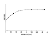
- FIG. 8 is a diagram illustrating the relationship between the shrink-fitting allowance and the iron loss.
- FIG. 9 is a diagram showing a comparison result between the iron loss ratio at the time of driving the conventional permanent magnet embedded electric motor and the iron loss ratio at the time of driving the embedded permanent magnet electric motor according to the embodiment of the present invention. It is.
- FIG. 10 is a first side view of the stator core.
- FIG. 11 is a second side view of the stator core.
- FIG. 1 is a longitudinal sectional view of a compressor provided with a permanent magnet embedded electric motor according to an embodiment of the present invention.
- 2 is a cross-sectional view taken along arrow AA shown in FIG.
- FIG. 3 is a detailed view of a main part of the permanent magnet embedded motor shown in FIG.
- FIG. 4 is a cross-sectional view taken along the line AA shown in FIG. 1 (cross-sectional view of the permanent magnet embedded electric motor excluding the frame).
- FIG. 5 is a cross-sectional view taken along line BB shown in FIG.
- FIG. 6 is a cross-sectional view taken along the line BB shown in FIG. 1 (cross-sectional view of the permanent magnet embedded electric motor excluding the frame).
- FIG. 1 is a longitudinal sectional view of a compressor provided with a permanent magnet embedded electric motor according to an embodiment of the present invention.
- 2 is a cross-sectional view taken along arrow AA shown in FIG.
- FIG. 3 is a detailed view of a main part
- FIG. 7 is a detailed view of the stator core.
- FIG. 8 is a diagram illustrating the relationship between the shrink-fitting allowance and the iron loss.
- FIG. 9 is a diagram showing a comparison result between the iron loss ratio at the time of driving the conventional permanent magnet embedded electric motor and the iron loss ratio at the time of driving the embedded permanent magnet electric motor according to the embodiment of the present invention. It is.
- FIG. 10 is a side view of the stator core.
- FIG. 11 is a second side view of the stator core.
- the frame 6 of the rotary compressor 1 is provided with an embedded permanent magnet electric motor 7 (hereinafter “electric motor 7”) and a compression element 14.
- the electric motor 7 includes a stator 80, a rotor 22, and a rotating shaft 10, and is, for example, a brushless DC motor.
- the stator 80 includes a stator core 8 and a stator winding 29, and the rotating shaft 10 is disposed near the center of the stator core 8.
- the electric motor 7 is used as an electric element of the hermetic rotary compressor 1, but the electric motor 7 can also be applied as an electric element of any device other than the rotary compressor 1.
- the compression element 14 includes, as main elements, a cylinder 12 provided in a vertically stacked state, a rotating shaft 10 that is rotated by the electric motor 7, a piston 13 that is fitted into the rotating shaft 10, and a cylinder 12 that compresses the inside of the cylinder 12 to the suction side. Attached to the upper frame 17, a vane (not shown) that is divided into a side, a pair of upper and lower frames (an upper frame 17 and a lower frame 16) that are rotatably inserted into the rotary shaft 10 and closes the axial end surface of the cylinder 12.
- the upper discharge muffler 11 and the lower discharge muffler 15 attached to the lower frame 16 are provided.
- the frame 6 is formed into a cylindrical shape by drawing a steel plate having a thickness of about 3 mm. Refrigerating machine oil (not shown) that lubricates each sliding portion of the compression element 14 is stored at the bottom of the frame 6. .
- the rotor 22 is disposed via a gap 26 (see FIG. 2) on the inner diameter side of the stator 8.
- the rotary shaft 10 is held in a freely rotatable state by bearing portions (upper frame 17 and lower frame 16) provided at the lower portion of the rotary compressor 1.
- the stator core 8 is held on the frame inner periphery 6b (see FIG. 3) by shrink fitting, for example. Electric power from the glass terminal 4 fixed to the frame 6 is supplied to the stator winding 29 wound around the stator core 8.
- the outer diameter of the stator core 8 is set larger than the inner diameter of the frame 6.
- a high temperature for example, 300 ° C.
- the frame 6 expands, and the expanded inner diameter of the frame 6 becomes larger than the outer diameter of the stator core 8 at normal temperature.
- the normal temperature stator core 8 is inserted into the high temperature frame 6.
- the frame 6 contracts, and the stator core 8 is fixed to the frame 6.
- shrink fitting In the stator core 8 after shrink fitting, a compressive stress is generated by the tightening force of the frame 6. Due to this compressive stress, the magnetic permeability of the electrical steel sheet constituting the stator core 8 is lowered and the iron loss is increased.
- FIG. 8 shows the relationship between the iron loss and the difference between the inner diameter dimension of the frame 6 and the outer diameter dimension of the stator core 8 at room temperature (shrink-fitting allowance).
- the stator core 8 has a donut shape whose outer diameter is slightly larger than the inner diameter of the frame 6.
- the shrink-fitting allowance at normal temperature varies depending on the weight of the stator core 8, but the larger the weight of the stator core 8, the greater the shrink-fitting allowance, which is about several tens to several hundreds of micrometers. For example, a compressive stress corresponding to a tightening force generated by contraction of the frame 6 at the time of shrink fitting is generated on the outer peripheral portion of the stator core 8.
- the compressive stress increases as the shrink-fit allowance increases.
- the iron loss of the electromagnetic steel plate which comprises the stator core 8 increases with this compressive stress as FIG. 8 shows.
- the iron loss due to compressive stress has a characteristic (saturation characteristic) that increases greatly with increasing compressive stress until the compressive stress reaches about 70 MPa, but decreases with increasing compressive stress.
- the iron loss with respect to the shrink-fitting allowance greatly increases in the region where the shrink-fitting allowance is 60 ⁇ m or less, and is saturated in the region where it is 60 ⁇ m or more.
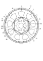
- FIG. 2 shows an electric motor 7 including a stator core 8 composed of a split core 8A and a rotor 22.
- a stator core 8 composed of a split core 8A and a rotor 22.
- six magnet insertion holes having a substantially regular hexagon are formed in the vicinity of the outer periphery thereof, and N poles and S poles are alternately attached to the magnet insertion holes.
- Six magnetized flat-plate rare earth permanent magnets (neodymium, iron, and boron as main components) are inserted.
- a shaft hole 21 is formed at the center of the rotor core 23, and a rotating shaft 10 (see FIG. 1) for transmitting rotational energy is connected to the shaft hole 21 by shrink fitting, press fitting, or the like.
- a plurality of air holes 25 serving as a refrigerant flow path are provided between the magnet insertion hole and the shaft hole 21, a plurality of air holes 25 serving as a refrigerant flow path are provided.
- the number of magnetic poles of the rotor 22 may be any number as long as it is two or more, but here, a case where the number of magnetic poles of the rotor 22 is six is illustrated.
- an Nd—Fe—B (neodymium-iron-boron) rare earth magnet is used as the permanent magnet, but the type of permanent magnet is not limited to this.
- the rare earth magnet used for the rotor 22 of the compressor electric motor 7 has a heavy rare earth element amount of Dy (dysprosium) in order to suppress a decrease in coercive force and a decrease in demagnetization characteristics at high temperatures. ) Is added.
- the electric motor 7 using the rotor 22 of the present embodiment performs variable speed drive by PWM control by an inverter of a drive circuit (not shown), thereby enabling high-efficiency operation in accordance with required product load conditions. It is carried out.
- the electric motor 7 using the rotor 22 of this Embodiment is mounted in the compressor of an air conditioner, for example, and guarantees the use in a high temperature atmosphere of 100 degreeC or more.
- a gap 26 is formed between the outer peripheral surface of the rotor core 23 and the inner peripheral surface of the stator core 8.
- the air gap 26 is 0.3 mm to 1 mm.
- the stator core 8 is an annular body arranged in an annular shape by punching a magnetic steel sheet having a thickness of about 0.1 mm to 0.7 mm into a predetermined shape, and connecting a plurality of punched divided core pieces with a connecting portion 27. Multiple sheets are stacked.
- the connection part 27 is comprised by a joint wrap or a thin connection part, for example.
- an electromagnetic steel sheet having a thickness of 0.35 mm is used.
- the stator core 8 is subjected to an annealing process after the electromagnetic steel sheets are laminated in order to alleviate distortion at the time of punching.
- Each divided core 8A constituting the stator core 8 is formed by laminating a plurality of divided core pieces, and is formed in a substantially T shape.
- the split core 8A includes a yoke 8A1, a magnetic pole tooth 8A2, and a tooth tip 8A3.
- a slot 8B is formed by a space defined by the yoke 8A1, the magnetic pole teeth 8A2, and the tooth tip 8A3.
- nine slots 8B arranged at substantially equal intervals in the circumferential direction are formed radially.
- the magnetic pole teeth 8A2 extend from the yoke 8A1 toward the center of the electric motor 7, and the width in the circumferential direction is formed to be substantially equal from the yoke 8A1 to the tooth tip 8A3.
- a stator winding 29 (see FIG. 1) that generates a rotating magnetic field is wound around the magnetic teeth 8A2.
- Teeth tip 8A3 is formed in an umbrella shape with both sides extending in the circumferential direction.
- the stator winding 29 is formed by winding a magnet wire directly around the magnetic pole teeth 8A2 via the insulating portion 9 (see FIG. 1). This winding method is called concentrated winding.
- the stator winding 29 is connected to a three-phase Y connection. The number of turns and the wire diameter of the stator winding 29 are determined in accordance with required characteristics (rotation speed, torque, etc.), voltage specifications, and slot cross-sectional area.
- the split core 8A is expanded in a strip shape so that the stator winding 29 can be easily wound, and a magnet wire having a wire diameter of about 0.8 mm is wound around each magnetic pole tooth 8A2 for about 100 turns, and then the split core
- the stator core 8 is formed by rounding and welding 8A in a ring shape.
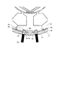
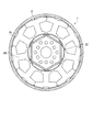
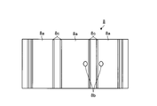
- Two protrusions 8c are provided on the outer peripheral portion 8a of the split core 8A.
- the center position of the stator core 8 is C
- the center position of the yoke 8A1 in the circumferential direction is D
- the line connecting the center position C and the center position D is the teeth center axis 30.
- each of the divided cores 8A is provided with two protrusions 8c at positions symmetrical with respect to the teeth central axis 30 in the circumferential direction.
- each protrusion 8 c is provided from one end of the stator core 8 in the axial direction to the other end.
- the protrusion 8c cannot be effectively used as a magnetic path when the electric motor 7 is driven, it is desirable that the height (step) from the tip of the protrusion 8c to the outer periphery 8a is small.
- the step is a distance about twice as large as the shrink-fitting allowance so that the portion of the outer peripheral portion 8a of the split core 8A that is not provided with the protruding portion 8c does not come into contact with the frame 6 when shrink-fitted. It is formed as follows.
- stator core 8 When the stator core 8 is incorporated into the frame 6, the stator core 8 is first temporarily fixed by shrink fitting with the frame 6 so that the protrusion 8 c fits with the frame inner peripheral portion 6 b (see FIG. 3).
- the split core 8 ⁇ / b> A constituting the stator core 8 is provided with two protrusions 8 c at positions that are symmetrical in the circumferential direction with respect to the tooth center axis 30. Therefore, each divided core 8A is shrink-fitted with an equal force from the outer peripheral side toward the axis center in this step, and a gap (divided gap) between adjacent divided cores 8A is reduced to ensure roundness. be able to.
- the roundness of the stator core 8 can be improved by providing a large number of the protrusions 8c that are evenly distributed in the circumferential direction.
- the stator core 8 shown in FIG. 2 has 18 protrusions 8c as an example. However, in order to improve the roundness, more protrusions 8c may be evenly distributed. desirable.
- the protrusion 8 c has an area on the frame inner peripheral part 6 b side (part where the protrusion 8 c contacts the frame inner peripheral part 6 b). It is desirable to form so that it may become 20% or less of the total area of the part 8a.
- the shrinkage allowance is 60 ⁇ m or less. This is because, as shown in FIG. 8, when the shrinkage allowance exceeds 60 ⁇ m, the increase in iron loss against the compressive stress is saturated. That is, if the difference between the inner diameter dimension of the frame 6 and the outer diameter dimension of the stator core 8 (shrink-fitting allowance) is 60 ⁇ m or less, the increase in iron loss after shrink-fitting can be greatly reduced. .
- a plurality of hollow portions 8b are provided in the outer peripheral portion 8a of the split core 8A.
- the position where the hollow portion 8b is formed is, for example, an angle obtained by dividing 360 by the divisor n (n is an integer of 3 or more) of the total number of the divided cores 8A among all the divided cores 8A in the circumferential direction. It is the outer peripheral part 8a of the split core 8A provided at equal intervals.
- the divisor n is 3 or 9.
- the divisor n is 3, and the three divided cores 8A denoted by reference symbols a, b, and c in FIG.
- Each of the divided cores 8A is provided with two recessed portions 8b.
- the recessed portion 8b is provided at a position symmetrical in the circumferential direction with respect to the tooth center axis 30 in the outer peripheral portion 8a of the divided core 8A.
- the recess 8b is provided only in the vicinity of the center between one end and the other end of the split core 8A with respect to the axial direction of the split core 8A.
- the hollow part 8b becomes a factor which narrows the magnetic path of the stator core 8 and deteriorates the magnetic characteristic of the electric motor 7, it is desirable to comprise so that the magnitude
- the recess 8b is formed with a circumferential width of about 4 mm, an axial length of about 5 mm, and a radial depth of about 2 mm. The depth in the radial direction is the length from the bottom 8d (see FIG. 3) of the recess 8b to the outer periphery 8a.
- hollow part 8b of the example of illustration is provided in the outer side between the two projection parts 8c formed in the division
- the pressing jig 24 having substantially the same size as or slightly smaller than the recessed portion 8 b and having a planar shape at the tip is attached to the outside of the frame 6.
- the frame 6 between the frame outer peripheral portion 6a pressed by the pressing jig 24 and the recess portion 8b is plastically deformed, and the deformed portion (pressing portion 6e) is sheared to the recess portion 8b.
- a concave portion 6c is formed in the frame outer peripheral portion 6a, and the columnar projection 6d (that is, the fixing portion 28) is closely engaged with the recess portion 8b, whereby the frame 6 and the stator core 8 are mutually connected.
- a fixing portion 28 for fixing the is formed.
- the divided core 8A is configured to come into contact with the frame inner peripheral portion 6b by the protrusion 8c. Therefore, the recessed portion 8b for locally fixing the stator core 8 to the frame 6 does not have to be formed in all the divided cores 8A constituting the stator core 8. That is, the locally fixed number can be made smaller than the total number of the divided cores 8A.
- the recessed portions 8 b may be provided near both end portions in the axial direction of the stator core 8 (both near one end and near the other end). .
- the stator core 8 is not easily displaced in the axial direction, and high reliability can be obtained.
- the circumferential position of the protrusion 8c is provided so that the central angle with respect to the teeth central axis 30 is 3 degrees to 10 degrees (A degree in the figure). desirable. Further, it is desirable that the circumferential position of the recess 8b is provided so that the central angle with respect to the tooth central axis 30 is 10 degrees to 15 degrees (B degrees in the figure). With this configuration, a uniform tightening force is applied to the split core 8A, and local fixing can be performed without reducing roundness.
- the stator core 8 configured in this way is shrink-fitted with an equal force from the outer peripheral side toward the axis center, and is locally fixed in a state where roundness is ensured. Accordingly, it is possible to prevent the divided core 8A from being fixed in a greatly distorted state due to the local tightening force at the time of local fixing. It can be fixed to 6b.
- the electric motor 7 according to the present embodiment has a good roundness, it can reduce vibration. Furthermore, the holding force necessary for fixing the stator core 8 to the frame 6 can be sufficiently secured by performing the local fixing.
- a local fixing method for example, a method of fixing the stator core 8 to the frame 6 by arc spot welding may be used.
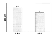
- FIG. 9 shows the iron loss ratio at the time of driving the conventional electric motor and the iron loss ratio at the time of driving the electric motor 7 according to the embodiment of the present invention.
- the configuration of the electric motor 7 according to the present embodiment is the same as that of the conventional electric motor except for the stator core 8.
- the electric motor 7 according to the present embodiment can reduce the iron loss by 19% compared to the conventional electric motor, and the efficiency of the electric motor 7 is greatly improved. I understand.
- the stress deterioration of iron loss is greater as the magnetic flux density is higher.
- Electric elements that use concentrated windings with high winding density and that use rare earth permanent magnets for the rotor have a high magnetic flux density, which is particularly effective in reducing iron loss by reducing compressive stress due to shrink fitting. growing.
- an electric motor using a rare earth magnet having a Dy content of 3% or less has a high magnetic flux density, the effect of improving the efficiency is particularly increased by using the stator core 8 according to the present embodiment.
- the performance improvement can also be directed to reducing the amount of magnets used.
- the refrigerant gas supplied from the accumulator 2 is sucked into the cylinder 12 through the suction pipe 3 fixed to the frame 6.
- the electric motor 7 is rotated by energization of the inverter, the piston 13 fitted to the rotating shaft 10 is rotated in the cylinder 12.
- the refrigerant is compressed in the cylinder 12.
- the refrigerant ascends in the frame 6 through the air holes of the electric motor 7. At this time, refrigeration oil is mixed in the compressed refrigerant.
- the mixture of the refrigerant and the refrigerating machine oil passes through the air hole provided in the rotor core, the separation of the refrigerant and the refrigerating machine oil is promoted, and the refrigerating machine oil can be prevented from flowing into the discharge pipe 5. In this way, the compressed refrigerant is supplied to the high pressure side of the refrigeration cycle through the discharge pipe 5 provided in the frame 6.
- R410A, R407C, R22 and the like are used as the refrigerant of the rotary compressor 1, but any refrigerant such as a low GWP (global warming potential) refrigerant can be applied. From the viewpoint of preventing global warming, a low GWP refrigerant is desired.
- a low GWP refrigerant there are the following refrigerants.
- HFO is an abbreviation for Hydro-Fluoro-Olefin
- Olefin is an unsaturated hydrocarbon having one double bond.
- the GFO of HFO-1234yf is 4.
- Hydrocarbon having a carbon double bond in the composition for example, R1270 (propylene).
- GWP is 3, which is smaller than HFO-1234yf, but flammability is larger than HFO-1234yf.
- stator core 8 is fixed to the frame 6 by shrink fitting.
- a method other than shrink fitting for example, cold fitting (method for cooling the stator 8), or press fitting is used.
- a brushless DC motor has been described as an example of the electric motor 7.
- the fixing method of the stator core 8 according to the present embodiment is an electric motor other than the brushless DC motor, for example, a permanent magnet of an induction motor.
- the present invention can also be applied to motors that are not used, and similar effects can be obtained with these motors.
- the electric motor 7 includes the stator core 8 in which three or more divided cores 8A arranged at equal central angles are arranged in an annular shape, and the stator core.
- 8 is a permanent magnet embedded type electric motor including a rotor 22 disposed on an inner diameter portion of the motor 8 and a frame 6 containing the split core 8A.
- the outer periphery 8a of each split core 8A includes a stator core 8 A plurality of protruding portions 8c projecting from the outer peripheral portion 8a toward the inner peripheral portion 6b of the frame at a position symmetrical in the circumferential direction with respect to a central axis (teeth central axis 30) connecting the center of the divided core 8A and the center of the divided core 8A
- the outer peripheral portion 8a of the divided core 8A provided at equal intervals in the circumferential direction at a central angle obtained by dividing 360 by the divisor n (n is an integer of 3 or more) of the total number of the divided cores 8A, At a position other than the position where the protrusion 8c is formed, and at the central axis In symmetrical positions in the circumferential direction and a plurality of depressed portions 8b direction becomes collision the dent shape of the outer peripheral portion 8a is formed from the frame inner periphery portion 6b.
- stator core 8 configured in this manner is temporarily fixed to the frame inner peripheral portion 6b by shrink fitting, the roundness of the stator core 8 is improved as compared with the prior art. Furthermore, by fixing the stator 8 locally to the inner periphery 6b of the frame after shrink fitting, it is possible to secure the pull-out load of the stator 8 and to minimize the places where the compressive stress is generated inside the core. Therefore, a reduction in efficiency of the electric motor 7 can be suppressed as compared with the prior art, and the electric motor 7 having high efficiency and high reliability can be obtained. In particular, it is highly effective in improving the efficiency of a rare earth-saving motor with a high magnetic flux density, and the performance improvement can be directed to reducing the amount of magnets used. By using the electric motor 7 described above, it is possible to configure a highly efficient compressor and refrigeration air conditioner with low noise and high reliability.
- the embodiment of the present invention shows an example of the contents of the present invention, and can be combined with another known technique, and a part thereof is not deviated from the gist of the present invention. Of course, it is possible to change the configuration such as omission.
- the present invention can be applied to a permanent magnet embedded electric motor, a compressor, and a refrigeration air conditioner, and in particular, as an invention that can improve reliability while securing a removal load of a stator core. Useful.
Abstract
A plurality of projections (8c) projecting from the outer periphery of divided cores (8A) toward the inner periphery of a frame is formed on the outer periphery of the divided cores (8A) at the position circumferentially symmetrical with respect to a central axis connecting the center of a stator core (8) and the center of the divided cores (8A). A plurality of recesses (8b) projecting from the inner periphery of the frame toward the outer periphery of the divided cores (8A) is formed on the outer periphery of the divided cores (8A) equidistantly provided in the circumferential direction at a center angle having a value obtained by dividing 360 by a divisor n (n is an integer of three or more) of the total number of the divided cores (8A) at the position circumferentially symmetrical with respect to the central axis.
Description
本発明は、永久磁石埋込型電動機、圧縮機、および冷凍空調装置に関するものである。
The present invention relates to a permanent magnet embedded electric motor, a compressor, and a refrigeration air conditioner.
圧縮機を駆動する電動機として永久磁石埋込型電動機が用いられている。圧縮機では、電動機の固定子鉄心(固定子コア)が円筒状の密閉容器(フレーム)の内周部に焼き嵌めで固定されることが多い。すなわち、固定子コアの外径よりわずかに小さい内径のフレームを製造し、このフレームを加熱して、フレーム内径が固定子コアの外径より大きくなるように熱膨張させる。そして、フレーム内径部に固定子コアを挿入した後、常温まで冷却する。これにより、フレーム内径が縮小し、フレームの締め付け力によって固定子コアがフレームに保持される。
An embedded permanent magnet electric motor is used as an electric motor for driving a compressor. In a compressor, the stator core (stator core) of an electric motor is often fixed to the inner peripheral portion of a cylindrical airtight container (frame) by shrink fitting. That is, a frame having an inner diameter slightly smaller than the outer diameter of the stator core is manufactured, and this frame is heated and thermally expanded so that the inner diameter of the frame is larger than the outer diameter of the stator core. And after inserting a stator core in an inner diameter part of a frame, it cools to normal temperature. As a result, the inner diameter of the frame is reduced, and the stator core is held on the frame by the tightening force of the frame.
焼き嵌めによって固定子コアをフレームに固定する場合、フレームの内周面(フレーム内周部)から軸中心方向へ向かう押圧力が固定子コアの外周面(固定子外周部)へ作用する。このとき、固定子外周部の全体がフレーム内周部に接している場合、前述した押圧力が固定子外周部の全周に加わり、固定子外周部の周方向の略全領域が圧縮応力を受ける。固定子外周部が圧縮応力を受けた場合、固定子コアを構成する電磁鋼板の透磁率が低下し、電磁鋼板(すなわち固定子コア)を流れる磁束量が減少して電動機のトルクが減少する。トルクの減少を補償するためには、固定子巻線に流す電流を増加させることで、固定子コアに流れる磁束量を増大させる必要があり、銅損およびインバータの通電損失が増加する。また圧縮応力を受けた場合、電磁鋼板の鉄損密度が増加し、電動機駆動時の鉄損が増大し、電動機の効率が低下する。
When the stator core is fixed to the frame by shrink fitting, a pressing force directed from the inner peripheral surface (frame inner peripheral portion) of the frame toward the axial center acts on the outer peripheral surface (stator outer peripheral portion) of the stator core. At this time, when the entire outer periphery of the stator is in contact with the inner periphery of the frame, the aforementioned pressing force is applied to the entire periphery of the stator outer periphery, and substantially the entire region in the circumferential direction of the stator outer periphery is subjected to compressive stress. receive. When the outer peripheral portion of the stator is subjected to compressive stress, the magnetic permeability of the electromagnetic steel sheet constituting the stator core is reduced, the amount of magnetic flux flowing through the electromagnetic steel sheet (that is, the stator core) is reduced, and the torque of the electric motor is reduced. In order to compensate for the decrease in torque, it is necessary to increase the amount of magnetic flux flowing through the stator core by increasing the current flowing through the stator winding, which increases copper loss and inverter energization loss. Further, when subjected to compressive stress, the iron loss density of the electromagnetic steel sheet increases, the iron loss at the time of driving the motor increases, and the efficiency of the motor decreases.
下記特許文献1に記される従来技術では、固定子外周部とフレーム内周部との間に、固定子外周部とフレーム内周部とが当接する当接面と、固定子外周部とフレーム内周部との間の空隙(非当接面)とが形成され、当接面の中心角度が130度の範囲内に設定されている。この構成により、焼き嵌めによって固定子コアをフレームに固定しながら効率の低下を抑制している。
In the related art described in Patent Document 1 below, a contact surface between the stator outer peripheral portion and the frame inner peripheral portion, and the stator outer peripheral portion and the frame are disposed between the stator outer peripheral portion and the frame inner peripheral portion. A gap (non-contact surface) between the inner peripheral portion and the inner peripheral portion is formed, and the center angle of the contact surface is set within a range of 130 degrees. With this configuration, the decrease in efficiency is suppressed while the stator core is fixed to the frame by shrink fitting.
また、下記特許文献2に記される従来技術では、フレーム内周部の軸方向長さが固定子コアの軸方向長さよりも小さく形成されている。さらに、この従来技術は、フレームの内径寸法が固定子コアの外径寸法よりも小さく形成された嵌合部を有する。そして、固定子外周部の嵌合部と対向する部分がこの嵌合部と嵌め合わされ、固定子外周部の嵌合部と対向する部分以外の部分(固定子外周部の非対向部)には隙間が形成され、さらに、固定子外周部の一部が固定子保持手段(アークスポット溶接など)によってフレームに保持されている。
In the prior art described in Patent Document 2 below, the axial length of the inner periphery of the frame is formed smaller than the axial length of the stator core. Furthermore, this prior art has a fitting part formed so that the inner diameter dimension of the frame is smaller than the outer diameter dimension of the stator core. And the part facing the fitting part of the stator outer peripheral part is fitted with this fitting part, and the part other than the part facing the fitting part of the stator outer peripheral part (non-opposing part of the stator outer peripheral part) A gap is formed, and a part of the outer periphery of the stator is held on the frame by stator holding means (such as arc spot welding).
しかしながら、上記特許文献1に記される従来技術では、固定子外周部とフレーム内周部との間の空隙により、固定子コアに作用する締め付け力が緩和されるものの、フレームが固定子コアを保持する力が低下するという課題があった。
However, in the prior art described in Patent Document 1, the gap between the outer periphery of the stator and the inner periphery of the frame reduces the tightening force acting on the stator core, but the frame does not support the stator core. There existed a subject that the power to hold | maintain fell.
また、上記特許文献2に記される従来技術では、嵌合部を形成することによって、圧縮応力の発生を抑制して高効率な電動機を得ることができる。ただし、この従来技術では、固定子外周部の非対向部がフレームと接触しないため、分割コアで構成された固定子コアをフレームに組み込む場合、局所的な外力が印加されると、この固定子コアには局所的な締め付け力が作用する。その結果、この固定子コアを構成する分割コアの一部が歪んだ状態で固定され、固定子コアの真円度が従来の接触構造のもの(焼き嵌めによる固定子コア)と比べて悪化し、音振動の要因となっていた。
Further, in the conventional technique described in Patent Document 2, by forming the fitting portion, it is possible to obtain a highly efficient electric motor by suppressing the generation of compressive stress. However, in this prior art, since the non-opposing portion of the outer periphery of the stator does not contact the frame, when a stator core composed of split cores is incorporated into the frame, the stator is subjected to a local external force applied. A local clamping force acts on the core. As a result, a part of the split core constituting the stator core is fixed in a distorted state, and the roundness of the stator core is worse than that of the conventional contact structure (stator core by shrink fitting). It was a factor of sound vibration.
本発明は、上記に鑑みてなされたものであって、分割コアで構成された固定子コアの抜け荷重を確保しつつ信頼性の高い永久磁石埋込型電動機、圧縮機、および冷凍空調装置を得ることを目的とする。
The present invention has been made in view of the above, and provides a highly reliable embedded permanent magnet electric motor, a compressor, and a refrigeration air conditioner while ensuring a removal load of a stator core composed of split cores. The purpose is to obtain.
上述した課題を解決し、目的を達成するために、本発明は、相互に等しい中心角で配置された3つ以上の分割コアが環状に配設されて成る固定子コアと、前記固定子コアの内径部に配置される回転子と、分割コアを内包するフレームとを備えた永久磁石埋込型電動機であって、前記各分割コアの外周部には、前記固定子コアの中心と前記分割コアの中心とを結ぶ中心軸に対して周方向に対称な位置において、前記外周部から前記フレームの内周部に向かって突状の複数の突起部が形成され、分割コアの総数の約数n(nは3以上の整数)で360を除した値の中心角で周方向に等間隔に設けられた分割コアの外周部には、前記突起部が形成される位置以外の位置、かつ、前記中心軸に対して周方向に対称な位置において、前記内周部から前記外周部の方向に突となる窪み状の複数の窪み部が形成されていること、を特徴とする。
In order to solve the above-described problems and achieve the object, the present invention provides a stator core in which three or more divided cores arranged at equal central angles are arranged in an annular shape, and the stator core A permanent magnet embedded type electric motor including a rotor disposed on an inner diameter portion of the rotor and a frame containing the split cores, and an outer peripheral portion of each split core includes a center of the stator core and the split cores. A plurality of projecting protrusions are formed from the outer peripheral portion toward the inner peripheral portion of the frame at a position symmetrical in the circumferential direction with respect to the central axis connecting the center of the core, and a divisor of the total number of divided cores n (n is an integer of 3 or more) divided by 360, and the outer periphery of the split core provided at equal intervals in the circumferential direction at a central angle is a position other than the position where the protrusion is formed, and Front from the inner periphery at a position symmetrical in the circumferential direction with respect to the central axis A plurality of recess recess shaped as a collision in the direction of the outer peripheral portion is formed, characterized by.
この発明によれば、分割コアで構成された固定子コアの抜け荷重を確保しつつ信頼性を高めることができる、という効果を奏する。
According to the present invention, there is an effect that the reliability can be improved while securing the removal load of the stator core constituted by the split cores.
以下に、本発明に係る永久磁石埋込型電動機、圧縮機、および冷凍空調装置の実施の形態を図面に基づいて詳細に説明する。なお、この実施の形態によりこの発明が限定されるものではない。
Hereinafter, embodiments of an embedded permanent magnet electric motor, a compressor, and a refrigerating and air-conditioning apparatus according to the present invention will be described in detail with reference to the drawings. Note that the present invention is not limited to the embodiments.
実施の形態.
図1は、本発明の実施の形態に係る永久磁石埋込型電動機を備えた圧縮機の縦断面図である。図2は、図1に示されるA-A矢視の断面図である。図3は、図2に示される永久磁石埋込型電動機の要部詳細図である。図4は、図1に示されるA-A矢視の断面図(フレームを除いた永久磁石埋込型電動機の断面図)である。図5は、図1に示されるB-B矢視の断面図である。図6は、図1に示されるB-B矢視の断面図(フレームを除いた永久磁石埋込型電動機の断面図)である。図7は、固定子コアの詳細図である。図8は、焼嵌締め代と鉄損との関係を示す図である。図9は、従来の永久磁石埋込型電動機の駆動時における鉄損比率と、と本発明の実施の形態に係る永久磁石埋込型電動機の駆動時における鉄損比率との比較結果を示す図である。図10は、固定子コアの側面図である。図11は、固定子コアの第2の側面図である。 Embodiment.
FIG. 1 is a longitudinal sectional view of a compressor provided with a permanent magnet embedded electric motor according to an embodiment of the present invention. 2 is a cross-sectional view taken along arrow AA shown in FIG. FIG. 3 is a detailed view of a main part of the permanent magnet embedded motor shown in FIG. FIG. 4 is a cross-sectional view taken along the line AA shown in FIG. 1 (cross-sectional view of the permanent magnet embedded electric motor excluding the frame). FIG. 5 is a cross-sectional view taken along line BB shown in FIG. FIG. 6 is a cross-sectional view taken along the line BB shown in FIG. 1 (cross-sectional view of the permanent magnet embedded electric motor excluding the frame). FIG. 7 is a detailed view of the stator core. FIG. 8 is a diagram illustrating the relationship between the shrink-fitting allowance and the iron loss. FIG. 9 is a diagram showing a comparison result between the iron loss ratio at the time of driving the conventional permanent magnet embedded electric motor and the iron loss ratio at the time of driving the embedded permanent magnet electric motor according to the embodiment of the present invention. It is. FIG. 10 is a side view of the stator core. FIG. 11 is a second side view of the stator core.
ロータリ圧縮機1のフレーム6には、永久磁石埋込型電動機7(以下「電動機7」)と圧縮要素14とが設けられている。電動機7は、固定子80と回転子22と回転軸10とから成り、例えばブラシレスDCモータである。固定子80は、固定子コア8と固定子巻線29とから成り、固定子コア8の中心付近には回転軸10が配置される。なお、本実施の形態では、密閉型のロータリ圧縮機1の電動要素として電動機7が用いられているが、電動機7は、ロータリ圧縮機1以外のあらゆる装置の電動要素としても適用可能である。
The frame 6 of the rotary compressor 1 is provided with an embedded permanent magnet electric motor 7 (hereinafter “electric motor 7”) and a compression element 14. The electric motor 7 includes a stator 80, a rotor 22, and a rotating shaft 10, and is, for example, a brushless DC motor. The stator 80 includes a stator core 8 and a stator winding 29, and the rotating shaft 10 is disposed near the center of the stator core 8. In the present embodiment, the electric motor 7 is used as an electric element of the hermetic rotary compressor 1, but the electric motor 7 can also be applied as an electric element of any device other than the rotary compressor 1.
圧縮要素14は、主な要素として、上下積層状態に設けられたシリンダ12と、電動機7により回転する回転軸10と、回転軸10に嵌挿されるピストン13と、シリンダ12内を吸入側と圧縮側に分けるベーン(図示せず)と、回転軸10が回転自在に嵌挿されシリンダ12の軸方向端面を閉塞する上下一対のフレーム(上部フレーム17および下部フレーム16)と、上部フレーム17に装着された上部吐出マフラ11と、下部フレーム16に装着された下部吐出マフラ15とを備える。フレーム6は、厚さ3mm程度の鋼板を絞り加工により円筒形状に形成され、フレーム6の底部には、圧縮要素14の各摺動部を潤滑する冷凍機油(図示せず)が貯留されている。
The compression element 14 includes, as main elements, a cylinder 12 provided in a vertically stacked state, a rotating shaft 10 that is rotated by the electric motor 7, a piston 13 that is fitted into the rotating shaft 10, and a cylinder 12 that compresses the inside of the cylinder 12 to the suction side. Attached to the upper frame 17, a vane (not shown) that is divided into a side, a pair of upper and lower frames (an upper frame 17 and a lower frame 16) that are rotatably inserted into the rotary shaft 10 and closes the axial end surface of the cylinder 12. The upper discharge muffler 11 and the lower discharge muffler 15 attached to the lower frame 16 are provided. The frame 6 is formed into a cylindrical shape by drawing a steel plate having a thickness of about 3 mm. Refrigerating machine oil (not shown) that lubricates each sliding portion of the compression element 14 is stored at the bottom of the frame 6. .
回転子22は、固定子8の内径側の空隙26(図2参照)を介して配置されている。回転軸10は、ロータリ圧縮機1の下部に設けた軸受け部(上部フレーム17および下部フレーム16)により回転自在な状態で保持されている。固定子コア8は、例えば焼き嵌めによりフレーム内周部6b(図3参照)に保持される。固定子コア8に巻回された固定子巻線29には、フレーム6に固定されるガラス端子4からの電力が供給される。
The rotor 22 is disposed via a gap 26 (see FIG. 2) on the inner diameter side of the stator 8. The rotary shaft 10 is held in a freely rotatable state by bearing portions (upper frame 17 and lower frame 16) provided at the lower portion of the rotary compressor 1. The stator core 8 is held on the frame inner periphery 6b (see FIG. 3) by shrink fitting, for example. Electric power from the glass terminal 4 fixed to the frame 6 is supplied to the stator winding 29 wound around the stator core 8.
以下、焼き嵌めについて説明する。常温において、固定子コア8の外径はフレーム6の内径よりも大きく設定される。このフレーム6を高温(例えば、300℃)に加熱することによってフレーム6が膨張し、膨張したフレーム6の内径寸法は、常温時の固定子コア8の外径寸法よりも大きくなる。この状態で常温の固定子コア8が高温のフレーム6に挿入される。その後、フレーム6の温度が下がるとフレーム6が収縮するため、フレーム6に固定子コア8が固定される。これを焼き嵌めという。焼き嵌め後の固定子コア8には、フレーム6の締め付け力によって圧縮応力が生じる。この圧縮応力により、固定子コア8を構成する電磁鋼板の透磁率が低下し、かつ、鉄損が増加する。
Hereinafter, shrink fitting will be described. At normal temperature, the outer diameter of the stator core 8 is set larger than the inner diameter of the frame 6. When the frame 6 is heated to a high temperature (for example, 300 ° C.), the frame 6 expands, and the expanded inner diameter of the frame 6 becomes larger than the outer diameter of the stator core 8 at normal temperature. In this state, the normal temperature stator core 8 is inserted into the high temperature frame 6. Thereafter, when the temperature of the frame 6 decreases, the frame 6 contracts, and the stator core 8 is fixed to the frame 6. This is called shrink fitting. In the stator core 8 after shrink fitting, a compressive stress is generated by the tightening force of the frame 6. Due to this compressive stress, the magnetic permeability of the electrical steel sheet constituting the stator core 8 is lowered and the iron loss is increased.
図8には、常温におけるフレーム6の内径寸法と固定子コア8の外径寸法との差(焼嵌締め代)と鉄損との関係が示されている。固定子コア8は、その外径寸法がフレーム6の内径寸法よりも僅かに大きいドーナツ形状である。常温における焼嵌締め代は、固定子コア8の重量によっても異なるが、固定子コア8の重量が大きいほど焼嵌締め代も大きく、数十から数百μm程度である。固定子コア8の外周部には、例えば焼き嵌め時におけるフレーム6の収縮で発生する締め付け力に応じた圧縮応力が発生する。
FIG. 8 shows the relationship between the iron loss and the difference between the inner diameter dimension of the frame 6 and the outer diameter dimension of the stator core 8 at room temperature (shrink-fitting allowance). The stator core 8 has a donut shape whose outer diameter is slightly larger than the inner diameter of the frame 6. The shrink-fitting allowance at normal temperature varies depending on the weight of the stator core 8, but the larger the weight of the stator core 8, the greater the shrink-fitting allowance, which is about several tens to several hundreds of micrometers. For example, a compressive stress corresponding to a tightening force generated by contraction of the frame 6 at the time of shrink fitting is generated on the outer peripheral portion of the stator core 8.
この締め付け力は、焼嵌締め代が大きくなるため、圧縮応力は焼嵌締め代が大きくなるほど大きくなる。そして、この圧縮応力により固定子コア8を構成する電磁鋼板の鉄損が図8に示されるように増加する。すなわち、圧縮応力による鉄損は、圧縮応力が70MPa程度までは圧縮応力の増加に対して大きく増加していくが、それ以上の圧縮応力に対しては小さくなる特性(飽和特性)を持つ。そのため、焼嵌締め代に対する鉄損は、焼嵌締め代が60μm以下の領域では大きく増加し、60μm以上の領域では飽和する。
Since this tightening force increases the shrink-fit allowance, the compressive stress increases as the shrink-fit allowance increases. And the iron loss of the electromagnetic steel plate which comprises the stator core 8 increases with this compressive stress as FIG. 8 shows. In other words, the iron loss due to compressive stress has a characteristic (saturation characteristic) that increases greatly with increasing compressive stress until the compressive stress reaches about 70 MPa, but decreases with increasing compressive stress. For this reason, the iron loss with respect to the shrink-fitting allowance greatly increases in the region where the shrink-fitting allowance is 60 μm or less, and is saturated in the region where it is 60 μm or more.
以下、この圧縮応力を低減する構成例を説明する。
Hereinafter, a configuration example for reducing the compressive stress will be described.
図2には、分割コア8Aで構成される固定子コア8と回転子22から成る電動機7が示されている。回転子22の回転子コア23には、その外周部近傍に略正六角形をなす6個の磁石挿入穴が形成され、各磁石挿入穴にはN極とS極とが交互になるように着磁された6枚の平板形状の希土類永久磁石(ネオジウム、鉄、ボロンを主成分とするもの)が挿入されている。また回転子コア23にはその中心にシャフト孔21が形成され、シャフト孔21には回転エネルギーを伝達するための回転軸10(図1参照)が焼き嵌めや圧入等により連結されている。磁石挿入孔とシャフト孔21との間には、冷媒の流路となる風穴25が複数設けられている。
FIG. 2 shows an electric motor 7 including a stator core 8 composed of a split core 8A and a rotor 22. In the rotor core 23 of the rotor 22, six magnet insertion holes having a substantially regular hexagon are formed in the vicinity of the outer periphery thereof, and N poles and S poles are alternately attached to the magnet insertion holes. Six magnetized flat-plate rare earth permanent magnets (neodymium, iron, and boron as main components) are inserted. A shaft hole 21 is formed at the center of the rotor core 23, and a rotating shaft 10 (see FIG. 1) for transmitting rotational energy is connected to the shaft hole 21 by shrink fitting, press fitting, or the like. Between the magnet insertion hole and the shaft hole 21, a plurality of air holes 25 serving as a refrigerant flow path are provided.
なお、回転子22の磁極数は、2極以上であればいくつでもよいが、ここでは、回転子22の磁極数が6極の場合を例示している。また本実施の形態では永久磁石としてNd-Fe-B(ネオジム-鉄-ボロン)系の希土類磁石を用いているが、永久磁石の種類はこれに限るものではない。また、圧縮機用の電動機7の回転子22に用いる希土類磁石には、高温時に保磁力が低下して減磁特性が低下するのを抑制するため、重希土類元素量であるDy(ディスプロシウム)を添加する。希土類磁石にDyを添加すると、保磁力が向上する反面、残留磁束密度が低下する特性を持ち、ここでは、希土類磁石のDy含有量が2%のものを使用している。また、本実施の形態の回転子22を用いた電動機7は、駆動回路(図示せず)のインバータによるPWM制御で可変速駆動を行うことにより、要求の製品負荷条件に合わせた高効率な運転を行っている。また、本実施の形態の回転子22を用いた電動機7は、例えば、空気調和機の圧縮機に搭載され、100℃以上の高温雰囲気中での使用を保証する。
The number of magnetic poles of the rotor 22 may be any number as long as it is two or more, but here, a case where the number of magnetic poles of the rotor 22 is six is illustrated. In this embodiment, an Nd—Fe—B (neodymium-iron-boron) rare earth magnet is used as the permanent magnet, but the type of permanent magnet is not limited to this. In addition, the rare earth magnet used for the rotor 22 of the compressor electric motor 7 has a heavy rare earth element amount of Dy (dysprosium) in order to suppress a decrease in coercive force and a decrease in demagnetization characteristics at high temperatures. ) Is added. When Dy is added to the rare earth magnet, the coercive force is improved, but the residual magnetic flux density is reduced. Here, a rare earth magnet having a Dy content of 2% is used. Further, the electric motor 7 using the rotor 22 of the present embodiment performs variable speed drive by PWM control by an inverter of a drive circuit (not shown), thereby enabling high-efficiency operation in accordance with required product load conditions. It is carried out. Moreover, the electric motor 7 using the rotor 22 of this Embodiment is mounted in the compressor of an air conditioner, for example, and guarantees the use in a high temperature atmosphere of 100 degreeC or more.
回転子コア23の外周面と固定子コア8の内周面との間には空隙26が形成される。この空隙26は0.3mmから1mmである。指令回転数に同期した周波数の電流を固定子コア8に通電することにより回転磁界が発生し、回転子コア23が回転する。
A gap 26 is formed between the outer peripheral surface of the rotor core 23 and the inner peripheral surface of the stator core 8. The air gap 26 is 0.3 mm to 1 mm. When a current having a frequency synchronized with the command rotational speed is applied to the stator core 8, a rotating magnetic field is generated, and the rotor core 23 rotates.
固定子コア8は、厚さ0.1mmから0.7mm程度の電磁鋼板を所定の形状に打ち抜き、打ち抜かれた複数の分割コア片を連結部27で連結することによって環状に配列した環状体が複数枚積層されたものである。連結部27は、例えば、ジョイントラップもしくは薄肉連結部で構成される。ここでは、板厚が0.35mmの電磁鋼板を用いている。固定子コア8は、電磁鋼板を積層後に、打ち抜き時の歪みを緩和するために焼鈍処理が行われる。
The stator core 8 is an annular body arranged in an annular shape by punching a magnetic steel sheet having a thickness of about 0.1 mm to 0.7 mm into a predetermined shape, and connecting a plurality of punched divided core pieces with a connecting portion 27. Multiple sheets are stacked. The connection part 27 is comprised by a joint wrap or a thin connection part, for example. Here, an electromagnetic steel sheet having a thickness of 0.35 mm is used. The stator core 8 is subjected to an annealing process after the electromagnetic steel sheets are laminated in order to alleviate distortion at the time of punching.
固定子コア8を構成する各分割コア8Aは、分割コア片が複数枚積層されたものであり、概略T字状に形成されている。分割コア8Aは、ヨーク8A1、磁極ティース8A2、およびティース先端部8A3を有して構成されている。ヨーク8A1、磁極ティース8A2、およびティース先端部8A3で区画される空間によってスロット8Bが形成される。
Each divided core 8A constituting the stator core 8 is formed by laminating a plurality of divided core pieces, and is formed in a substantially T shape. The split core 8A includes a yoke 8A1, a magnetic pole tooth 8A2, and a tooth tip 8A3. A slot 8B is formed by a space defined by the yoke 8A1, the magnetic pole teeth 8A2, and the tooth tip 8A3.
図示例では、周方向に略等間隔に配置された9個のスロット8Bが放射状に形成されている。磁極ティース8A2は、ヨーク8A1から電動機7の中心の方向に延び、その周方向の幅は、ヨーク8A1からティース先端部8A3にかけて略等しくなるように形成されている。磁極ティース8A2には、回転磁界を発生させる固定子巻線29(図1参照)が巻かれている。ティース先端部8A3は両サイドが周方向に広がる傘状に形成される。
In the illustrated example, nine slots 8B arranged at substantially equal intervals in the circumferential direction are formed radially. The magnetic pole teeth 8A2 extend from the yoke 8A1 toward the center of the electric motor 7, and the width in the circumferential direction is formed to be substantially equal from the yoke 8A1 to the tooth tip 8A3. A stator winding 29 (see FIG. 1) that generates a rotating magnetic field is wound around the magnetic teeth 8A2. Teeth tip 8A3 is formed in an umbrella shape with both sides extending in the circumferential direction.
固定子巻線29は、マグネットワイヤを、絶縁部9(図1参照)を介して磁極ティース8A2に直接巻き付けて形成される。この巻線方式を集中巻線という。そして、固定子巻線29は3相Y結線に結線される。固定子巻線29のターン数や線径は、要求される特性(回転数やトルク等)、電圧仕様、スロットの断面積に応じて定まる。本実施の形態では、固定子巻線29が巻き易いように、分割コア8Aを帯状に展開し、線径φ0.8mm程度のマグネットワイヤを各磁極ティース8A2に100ターン程度巻き付け、その後に分割コア8Aを環状に丸めて溶接し、固定子コア8を構成している。
The stator winding 29 is formed by winding a magnet wire directly around the magnetic pole teeth 8A2 via the insulating portion 9 (see FIG. 1). This winding method is called concentrated winding. The stator winding 29 is connected to a three-phase Y connection. The number of turns and the wire diameter of the stator winding 29 are determined in accordance with required characteristics (rotation speed, torque, etc.), voltage specifications, and slot cross-sectional area. In the present embodiment, the split core 8A is expanded in a strip shape so that the stator winding 29 can be easily wound, and a magnet wire having a wire diameter of about 0.8 mm is wound around each magnetic pole tooth 8A2 for about 100 turns, and then the split core The stator core 8 is formed by rounding and welding 8A in a ring shape.
分割コア8Aの外周部8aには2つの突起部8cが設けられている。図7において、例えば固定子コア8の中心位置をCとし、ヨーク8A1の周方向における中心位置をDとし、中心位置Cと中心位置Dとを結ぶ線をティース中心軸30とする。このとき、各分割コア8Aには、ティース中心軸30に対して周方向に対称な位置に2つの突起部8cが設けられている。また、図10に示されるように、各突起部8cは、固定子コア8の軸方向の一端から他端に渡って設けられている。
Two protrusions 8c are provided on the outer peripheral portion 8a of the split core 8A. 7, for example, the center position of the stator core 8 is C, the center position of the yoke 8A1 in the circumferential direction is D, and the line connecting the center position C and the center position D is the teeth center axis 30. At this time, each of the divided cores 8A is provided with two protrusions 8c at positions symmetrical with respect to the teeth central axis 30 in the circumferential direction. Further, as shown in FIG. 10, each protrusion 8 c is provided from one end of the stator core 8 in the axial direction to the other end.
なお、突起部8cは、電動機7が駆動する際の磁路として有効に利用することができないため、突起部8cの先端から外周部8aまでの高さ(段差)は、小さいことが望ましい。本実施の形態では、分割コア8Aの外周部8aの内、突起部8cを設けていない部分が焼き嵌め時にフレーム6と接触しないように、段差が焼嵌締め代の2倍程度の距離となるように形成されている。
In addition, since the protrusion 8c cannot be effectively used as a magnetic path when the electric motor 7 is driven, it is desirable that the height (step) from the tip of the protrusion 8c to the outer periphery 8a is small. In the present embodiment, the step is a distance about twice as large as the shrink-fitting allowance so that the portion of the outer peripheral portion 8a of the split core 8A that is not provided with the protruding portion 8c does not come into contact with the frame 6 when shrink-fitted. It is formed as follows.
固定子コア8をフレーム6に組み込む場合、突起部8cがフレーム内周部6b(図3参照)と嵌め合うように、まず固定子コア8がフレーム6によって焼き嵌めで仮止めされる。固定子コア8を構成する分割コア8Aには、ティース中心軸30に対して周方向に対称な位置に、2つの突起部8cが設けられている。そのため、各分割コア8Aは、本工程により、外周側からの軸中心に向かう均等な力で焼き嵌めされ、隣接する分割コア8Aの間の隙間(分割隙間)が縮まり、真円度を確保することができる。
When the stator core 8 is incorporated into the frame 6, the stator core 8 is first temporarily fixed by shrink fitting with the frame 6 so that the protrusion 8 c fits with the frame inner peripheral portion 6 b (see FIG. 3). The split core 8 </ b> A constituting the stator core 8 is provided with two protrusions 8 c at positions that are symmetrical in the circumferential direction with respect to the tooth center axis 30. Therefore, each divided core 8A is shrink-fitted with an equal force from the outer peripheral side toward the axis center in this step, and a gap (divided gap) between adjacent divided cores 8A is reduced to ensure roundness. be able to.
なお、突起部8cが周方向に均等に分散して数多く設けられている方が固定子コア8の真円度を向上させることができる。図2に示される固定子コア8には一例として18個の突起部8cが設けられているが、真円度の向上を図る観点ではより多くの突起部8cを均等に分散して設けることが望ましい。
In addition, the roundness of the stator core 8 can be improved by providing a large number of the protrusions 8c that are evenly distributed in the circumferential direction. The stator core 8 shown in FIG. 2 has 18 protrusions 8c as an example. However, in order to improve the roundness, more protrusions 8c may be evenly distributed. desirable.
また、仮止めとしての焼き嵌めでは、固定子コア8が抜けないような大きな力を与えるのではなく、分割隙間を吸収する程度の力が固定子コア8に与えられる。このことにより、固定子コア8の内部には、従来の焼き嵌め時のような大きな圧縮応力が発生しない。固定子コア8に大きな圧縮応力を加えないようにするため、突起部8cは、フレーム内周部6b側(突起部8cがフレーム内周部6bと接する部分)の面積が各分割コア8Aの外周部8aの総面積の20%以下となるように形成することが望ましい。
Further, in shrink fitting as temporary fixing, a large force that does not allow the stator core 8 to come off is given, but a force that absorbs the split gap is given to the stator core 8. As a result, a large compressive stress is not generated inside the stator core 8 as in the case of conventional shrink fitting. In order not to apply a large compressive stress to the stator core 8, the protrusion 8 c has an area on the frame inner peripheral part 6 b side (part where the protrusion 8 c contacts the frame inner peripheral part 6 b). It is desirable to form so that it may become 20% or less of the total area of the part 8a.
また、固定子コア8に大きな圧縮応力を加えないようにするためには、焼嵌締め代が60μm以下となることが望ましい。これは、図8に示したように焼嵌締め代が60μmを超えると圧縮応力に対する鉄損増加が飽和してしまうためである。すなわち、フレーム6の内径寸法と固定子コア8の外径寸法との差(焼嵌締め代)が60μm以下となるように構成すれば、焼き嵌め後の鉄損増加を大きく低減することができる。
Further, in order not to apply a large compressive stress to the stator core 8, it is desirable that the shrinkage allowance is 60 μm or less. This is because, as shown in FIG. 8, when the shrinkage allowance exceeds 60 μm, the increase in iron loss against the compressive stress is saturated. That is, if the difference between the inner diameter dimension of the frame 6 and the outer diameter dimension of the stator core 8 (shrink-fitting allowance) is 60 μm or less, the increase in iron loss after shrink-fitting can be greatly reduced. .
次に窪み部8bを説明する。図2において、分割コア8Aの外周部8aには複数の窪み部8bが設けられている。窪み部8bが形成される位置は、例えば、全ての分割コア8Aの内、分割コア8Aの総数の約数n(nは3以上の整数)で360を除した値の角度で、周方向に等間隔に設けられた分割コア8Aの外周部8aである。分割コア8Aの総数が9個の場合、約数nが3または9となる。本実施の形態では約数nを3としており、図2において符号a,b,cが付された3つの分割コア8Aは、120度で周方向に等間隔に設けられている。これらの分割コア8Aには、それぞれ2つの窪み部8bが設けられている。窪み部8bは、分割コア8Aの外周部8aにおいて、ティース中心軸30に対して周方向に対称な位置に設けられている。
Next, the depression 8b will be described. In FIG. 2, a plurality of hollow portions 8b are provided in the outer peripheral portion 8a of the split core 8A. The position where the hollow portion 8b is formed is, for example, an angle obtained by dividing 360 by the divisor n (n is an integer of 3 or more) of the total number of the divided cores 8A among all the divided cores 8A in the circumferential direction. It is the outer peripheral part 8a of the split core 8A provided at equal intervals. When the total number of the divided cores 8A is 9, the divisor n is 3 or 9. In the present embodiment, the divisor n is 3, and the three divided cores 8A denoted by reference symbols a, b, and c in FIG. 2 are provided at equal intervals in the circumferential direction at 120 degrees. Each of the divided cores 8A is provided with two recessed portions 8b. The recessed portion 8b is provided at a position symmetrical in the circumferential direction with respect to the tooth center axis 30 in the outer peripheral portion 8a of the divided core 8A.
また、図10に示されるように、窪み部8bは、分割コア8Aの軸方向に対して、分割コア8Aの一端と他端との間の中心付近のみに設けられている。なお、窪み部8bは、固定子コア8の磁路を狭くして電動機7の磁気特性を悪化させる要因となるため、その大きさが小さくなるように構成することが望ましい。窪み部8bは、例えば周方向の幅が約4mm、軸方向の長さが約5mm、径方向の深さが約2mmで形成されている。径方向の深さは、窪み部8bの底部8d(図3参照)から外周部8aまでの長さである。
Further, as shown in FIG. 10, the recess 8b is provided only in the vicinity of the center between one end and the other end of the split core 8A with respect to the axial direction of the split core 8A. In addition, since the hollow part 8b becomes a factor which narrows the magnetic path of the stator core 8 and deteriorates the magnetic characteristic of the electric motor 7, it is desirable to comprise so that the magnitude | size may become small. For example, the recess 8b is formed with a circumferential width of about 4 mm, an axial length of about 5 mm, and a radial depth of about 2 mm. The depth in the radial direction is the length from the bottom 8d (see FIG. 3) of the recess 8b to the outer periphery 8a.
なお、図示例の窪み部8bは、分割コア8Aに形成された2つの突起部8cの間(図7の中心位置D付近)の外側に設けられているが、2つの突起部8cの間に設けてもよい。
In addition, although the hollow part 8b of the example of illustration is provided in the outer side between the two projection parts 8c formed in the division | segmentation core 8A (near center position D of FIG. 7), it is between two projection parts 8c. It may be provided.
焼き嵌め後に固定子コア8を固定する場合、図3に示されるように、窪み部8bと略同一寸法または僅かに小さく、かつ、先端が平面形状である押付け治具24を、フレーム6の外側から窪み部8bの底部8dに向けて押し付ける。このことにより、押付け治具24で押されたフレーム外周部6aと窪み部8bとの間のフレーム6が塑性変形し、この変形した部分(押付部6e)がせん断された状態で窪み部8bに入り込む。その結果、フレーム外周部6aには凹部6cが形成され、円柱状の突部6d(すなわち固定部28)が窪み部8bと緊密に係合することによって、フレーム6と固定子コア8とを相互を固定する固定部28が形成される。
When the stator core 8 is fixed after shrink fitting, as shown in FIG. 3, the pressing jig 24 having substantially the same size as or slightly smaller than the recessed portion 8 b and having a planar shape at the tip is attached to the outside of the frame 6. To the bottom 8d of the depression 8b. As a result, the frame 6 between the frame outer peripheral portion 6a pressed by the pressing jig 24 and the recess portion 8b is plastically deformed, and the deformed portion (pressing portion 6e) is sheared to the recess portion 8b. Get in. As a result, a concave portion 6c is formed in the frame outer peripheral portion 6a, and the columnar projection 6d (that is, the fixing portion 28) is closely engaged with the recess portion 8b, whereby the frame 6 and the stator core 8 are mutually connected. A fixing portion 28 for fixing the is formed.
本実施の形態では、突起部8cによって分割コア8Aがフレーム内周部6bに接触するように構成されている。そのため、フレーム6に固定子コア8を局所固定するための窪み部8bは、固定子コア8を構成する全ての分割コア8Aに形成する必要はない。すなわち、局所固定の数は分割コア8Aの総数よりも少なくすることができる。
In the present embodiment, the divided core 8A is configured to come into contact with the frame inner peripheral portion 6b by the protrusion 8c. Therefore, the recessed portion 8b for locally fixing the stator core 8 to the frame 6 does not have to be formed in all the divided cores 8A constituting the stator core 8. That is, the locally fixed number can be made smaller than the total number of the divided cores 8A.
また、局所固定による保持力の観点では、図11に示されるように、窪み部8bは固定子コア8の軸方向の両端部付近(一端付近と他端付近との双方)に設けてもよい。この構成により、固定子コア8が軸方向にずれ難くなり、高い信頼性を得ることができる。
Further, from the viewpoint of the holding force by local fixation, as shown in FIG. 11, the recessed portions 8 b may be provided near both end portions in the axial direction of the stator core 8 (both near one end and near the other end). . With this configuration, the stator core 8 is not easily displaced in the axial direction, and high reliability can be obtained.
また、図7に示されるように、突起部8cの周方向の位置は、ティース中心軸30に対する中心角が3度から10度(図中のA度)となるように設けられていることが望ましい。また、窪み部8bの周方向の位置は、ティース中心軸30に対する中心角が10度から15度(図中のB度)となるように設けられていることが望ましい。この構成により、分割コア8Aに均等な締め付け力が印加され、真円度を低下させることなく局所固定することができる。
Further, as shown in FIG. 7, the circumferential position of the protrusion 8c is provided so that the central angle with respect to the teeth central axis 30 is 3 degrees to 10 degrees (A degree in the figure). desirable. Further, it is desirable that the circumferential position of the recess 8b is provided so that the central angle with respect to the tooth central axis 30 is 10 degrees to 15 degrees (B degrees in the figure). With this configuration, a uniform tightening force is applied to the split core 8A, and local fixing can be performed without reducing roundness.
このように構成された固定子コア8は、外周側からの軸中心に向かう均等な力で焼き嵌めされ、真円度が確保された状態で局所固定される。従って、局所固定時の局所的な締め付け力によって分割コア8Aが大きく歪んだ状態で固定されるということを抑制することができ、固定子コア8は、真円度の良い状態でフレーム内周部6bに固定することができる。
The stator core 8 configured in this way is shrink-fitted with an equal force from the outer peripheral side toward the axis center, and is locally fixed in a state where roundness is ensured. Accordingly, it is possible to prevent the divided core 8A from being fixed in a greatly distorted state due to the local tightening force at the time of local fixing. It can be fixed to 6b.
また、固定子コア8の内周部には、焼き嵌めによる従来の圧縮応力よりも小さい圧縮応力が生じる。また、局所固定による応力も部分的なものである。そのため、従来の固定方法に比べて、電動機全体での圧縮応力が小さくなり、固定子コア8の固定に伴う鉄損の増加が小さくなる。
Also, a compressive stress smaller than the conventional compressive stress due to shrink fitting is generated in the inner peripheral portion of the stator core 8. Moreover, the stress by local fixation is also partial. Therefore, compared with the conventional fixing method, the compressive stress in the whole electric motor becomes small, and the increase in the iron loss accompanying fixing of the stator core 8 becomes small.
また、本実施の形態に係る電動機7は、真円度も良いため低振動化を図ることができる。さらに、局所固定を行うことによって、固定子コア8をフレーム6に固定させるために必要な保持力も十分に確保することができる。なお、局所固定の方法としては、例えばアークスポット溶接によって固定子コア8をフレーム6に固定する方法を用いてもよい。
Moreover, since the electric motor 7 according to the present embodiment has a good roundness, it can reduce vibration. Furthermore, the holding force necessary for fixing the stator core 8 to the frame 6 can be sufficiently secured by performing the local fixing. As a local fixing method, for example, a method of fixing the stator core 8 to the frame 6 by arc spot welding may be used.
図9には、従来の電動機の駆動時の鉄損比率と、本発明の実施の形態に係る電動機7の駆動時における鉄損比率とが示されている。なお、本実施の形態に係る電動機7の構成は、固定子コア8を除き、従来の電動機の構成と同一である。図9の比較結果からも明らかなように、本実施の形態に係る電動機7は、従来の電動機に比べ鉄損を19%低減することができ、電動機7の効率が大幅に改善していることが分かる。鉄損の応力劣化は磁束密度が高い程大きい。巻線の密度が高い集中巻線を採用し、かつ、回転子に希土類永久磁石を使用した電動要素では、磁束密度が高いため、焼き嵌めによる圧縮応力を低減したことによる鉄損低減効果が特に大きくなる。特に、Dy含有量が3%以下の希土類磁石を用いた電動機では磁束密度が高いため、本実施の形態に係る固定子コア8を用いることによって効率改善の効果が特に大きくなる。また、性能改善分は磁石使用量の削減に振り向けることもできる。
FIG. 9 shows the iron loss ratio at the time of driving the conventional electric motor and the iron loss ratio at the time of driving the electric motor 7 according to the embodiment of the present invention. The configuration of the electric motor 7 according to the present embodiment is the same as that of the conventional electric motor except for the stator core 8. As is clear from the comparison results of FIG. 9, the electric motor 7 according to the present embodiment can reduce the iron loss by 19% compared to the conventional electric motor, and the efficiency of the electric motor 7 is greatly improved. I understand. The stress deterioration of iron loss is greater as the magnetic flux density is higher. Electric elements that use concentrated windings with high winding density and that use rare earth permanent magnets for the rotor have a high magnetic flux density, which is particularly effective in reducing iron loss by reducing compressive stress due to shrink fitting. growing. In particular, since an electric motor using a rare earth magnet having a Dy content of 3% or less has a high magnetic flux density, the effect of improving the efficiency is particularly increased by using the stator core 8 according to the present embodiment. The performance improvement can also be directed to reducing the amount of magnets used.
次に、係るロータリ圧縮機1の動作について説明する。アキュームレータ2から供給された冷媒ガスは、フレーム6に固定された吸入パイプ3よりシリンダ12内へ吸入される。インバータの通電によって電動機7が回転されていることで、回転軸10に嵌合されたピストン13がシリンダ12内で回転される。それにより、シリンダ12内では冷媒の圧縮が行われる。冷媒は、マフラを経た後、電動機7の風穴等を通ってフレーム6内を上昇する。このとき、圧縮された冷媒には冷凍機油が混入している。この冷媒と冷凍機油の混合物は、ロータ鉄心に設けた風穴を通過する際に、冷媒と冷凍機油との分離を促進され、冷凍機油が吐出パイプ5へ流入するのを防止できる。このようにして、圧縮された冷媒が、フレーム6に設けられた吐出パイプ5を通って冷凍サイクルの高圧側へと供給される。
Next, the operation of the rotary compressor 1 will be described. The refrigerant gas supplied from the accumulator 2 is sucked into the cylinder 12 through the suction pipe 3 fixed to the frame 6. When the electric motor 7 is rotated by energization of the inverter, the piston 13 fitted to the rotating shaft 10 is rotated in the cylinder 12. Thereby, the refrigerant is compressed in the cylinder 12. After passing through the muffler, the refrigerant ascends in the frame 6 through the air holes of the electric motor 7. At this time, refrigeration oil is mixed in the compressed refrigerant. When the mixture of the refrigerant and the refrigerating machine oil passes through the air hole provided in the rotor core, the separation of the refrigerant and the refrigerating machine oil is promoted, and the refrigerating machine oil can be prevented from flowing into the discharge pipe 5. In this way, the compressed refrigerant is supplied to the high pressure side of the refrigeration cycle through the discharge pipe 5 provided in the frame 6.
なお、ロータリ圧縮機1の冷媒には、従来からR410A、R407C、R22等が用いられているが、低GWP(地球温暖化係数)の冷媒等などいかなる冷媒も適用できる。地球温暖化防止の観点からは、低GWP冷媒が望まれている。低GWP冷媒の代表例として、以下の冷媒がある。
(1)組成中に炭素の二重結合を有するハロゲン化炭化水素:例えば、HFO-1234yf(CF3CF=CH2)である。HFOは、Hydro-Fluoro-Olefinの略で、Olefinは、二重結合を一つ持つ不飽和炭化水素のことである。尚、HFO-1234yfのGWPは4である。
(2)組成中に炭素の二重結合を有する炭化水素:例えば、R1270(プロピレン)である。尚、GWPは3で、HFO-1234yfより小さいが、可燃性はHFO-1234yfより大きい。
(3)組成中に炭素の二重結合を有するハロゲン化炭化水素または組成中に炭素の二重結合を有する炭化水素の少なくともいずれかを含む混合物:例えば、HFO-1234yfとR32との混合物等である。HFO-1234yfは、低圧冷媒のため圧損が大きくなり、冷凍サイクル(特に、蒸発器において)の性能が低下しやすい。そのため、HFO-1234yfより高圧冷媒であるR32又はR41等との混合物が実用上は有力になる。 Conventionally, R410A, R407C, R22 and the like are used as the refrigerant of therotary compressor 1, but any refrigerant such as a low GWP (global warming potential) refrigerant can be applied. From the viewpoint of preventing global warming, a low GWP refrigerant is desired. As typical examples of the low GWP refrigerant, there are the following refrigerants.
(1) Halogenated hydrocarbon having a carbon double bond in the composition: for example, HFO-1234yf (CF3CF = CH2). HFO is an abbreviation for Hydro-Fluoro-Olefin, and Olefin is an unsaturated hydrocarbon having one double bond. The GFO of HFO-1234yf is 4.
(2) Hydrocarbon having a carbon double bond in the composition: for example, R1270 (propylene). GWP is 3, which is smaller than HFO-1234yf, but flammability is larger than HFO-1234yf.
(3) a mixture containing at least one of a halogenated hydrocarbon having a carbon double bond in the composition or a hydrocarbon having a carbon double bond in the composition: for example, a mixture of HFO-1234yf and R32 is there. Since HFO-1234yf is a low-pressure refrigerant, its pressure loss is large, and the performance of the refrigeration cycle (especially in an evaporator) tends to deteriorate. Therefore, a mixture with R32 or R41, which is a high-pressure refrigerant, is more effective than HFO-1234yf in practical use.
(1)組成中に炭素の二重結合を有するハロゲン化炭化水素:例えば、HFO-1234yf(CF3CF=CH2)である。HFOは、Hydro-Fluoro-Olefinの略で、Olefinは、二重結合を一つ持つ不飽和炭化水素のことである。尚、HFO-1234yfのGWPは4である。
(2)組成中に炭素の二重結合を有する炭化水素:例えば、R1270(プロピレン)である。尚、GWPは3で、HFO-1234yfより小さいが、可燃性はHFO-1234yfより大きい。
(3)組成中に炭素の二重結合を有するハロゲン化炭化水素または組成中に炭素の二重結合を有する炭化水素の少なくともいずれかを含む混合物:例えば、HFO-1234yfとR32との混合物等である。HFO-1234yfは、低圧冷媒のため圧損が大きくなり、冷凍サイクル(特に、蒸発器において)の性能が低下しやすい。そのため、HFO-1234yfより高圧冷媒であるR32又はR41等との混合物が実用上は有力になる。 Conventionally, R410A, R407C, R22 and the like are used as the refrigerant of the
(1) Halogenated hydrocarbon having a carbon double bond in the composition: for example, HFO-1234yf (CF3CF = CH2). HFO is an abbreviation for Hydro-Fluoro-Olefin, and Olefin is an unsaturated hydrocarbon having one double bond. The GFO of HFO-1234yf is 4.
(2) Hydrocarbon having a carbon double bond in the composition: for example, R1270 (propylene). GWP is 3, which is smaller than HFO-1234yf, but flammability is larger than HFO-1234yf.
(3) a mixture containing at least one of a halogenated hydrocarbon having a carbon double bond in the composition or a hydrocarbon having a carbon double bond in the composition: for example, a mixture of HFO-1234yf and R32 is there. Since HFO-1234yf is a low-pressure refrigerant, its pressure loss is large, and the performance of the refrigeration cycle (especially in an evaporator) tends to deteriorate. Therefore, a mixture with R32 or R41, which is a high-pressure refrigerant, is more effective than HFO-1234yf in practical use.
以上のように構成されたロータリ圧縮機1に電動機7を用いることによって高効率で信頼性の高い圧縮機を得ることができる。また、冷凍空調装置にこのロータリ圧縮機1を用いることによって、高効率かつ低騒音で信頼性の高い冷凍空調装置を得ることができる。
By using the electric motor 7 for the rotary compressor 1 configured as described above, a highly efficient and highly reliable compressor can be obtained. Moreover, by using this rotary compressor 1 for a refrigeration air conditioner, a highly efficient refrigeration air conditioner with low noise and high reliability can be obtained.
なお、本実施の形態では、焼き嵌めによって固定子コア8をフレーム6に固定する例を説明したが、焼き嵌め以外の方法、例えば、冷し嵌め(固定子8を冷却する方法)、あるいは圧入等の方法を適用してもよい。また、本実施の形態では、電動機7としてブラシレスDCモータを例に説明したが、本実施の形態に係る固定子コア8の固定方法は、ブラシレスDCモータ以外の電動機、例えば誘導電動機の永久磁石を用いないモータにも適用でき、これらのモータにおいても同様の効果を得ることができる。
In this embodiment, the example in which the stator core 8 is fixed to the frame 6 by shrink fitting has been described. However, a method other than shrink fitting, for example, cold fitting (method for cooling the stator 8), or press fitting is used. Such a method may be applied. In the present embodiment, a brushless DC motor has been described as an example of the electric motor 7. However, the fixing method of the stator core 8 according to the present embodiment is an electric motor other than the brushless DC motor, for example, a permanent magnet of an induction motor. The present invention can also be applied to motors that are not used, and similar effects can be obtained with these motors.
以上に説明したように、本実施の形態に係る電動機7は、相互に等しい中心角で配置された3つ以上の分割コア8Aが環状に配設されて成る固定子コア8と、固定子コア8の内径部に配置される回転子22と、分割コア8Aを内包するフレーム6とを備えた永久磁石埋込型電動機であって、各分割コア8Aの外周部8aには、固定子コア8の中心と分割コア8Aの中心とを結ぶ中心軸(ティース中心軸30)に対して周方向に対称な位置において、外周部8aからフレーム内周部6bに向かって突状の複数の突起部8cが形成され、分割コア8Aの総数の約数n(nは3以上の整数)で360を除した値の中心角で周方向に等間隔に設けられた分割コア8Aの外周部8aには、突起部8cが形成される位置以外の位置、かつ、前記中心軸に対して周方向に対称な位置において、フレーム内周部6bから外周部8aの方向に突となる窪み状の複数の窪み部8bが形成されている。この構成ように構成された固定子コア8は、焼き嵌めでフレーム内周部6bに仮止めされるため、従来技術よりも固定子コア8の真円度が向上する。さらに、焼き嵌め後に固定子8をフレーム内周部6bに局所固定することによって、固定子8の抜け荷重を確保し、かつ、コア内部の圧縮応力発生箇所を最小限に止めることができる。従って、従来技術に比べて電動機7の効率の低下を抑制することができ、高効率で信頼性の高い電動機7を得ることができる。特に、磁束密度の高い省レアアースモータの効率改善に効果が高く、性能改善分を磁石使用量の削減に振り向けることもできる。上記の電動機7を用いることにより、高効率かつ低騒音な信頼性の高い圧縮機や冷凍空調機を構成することができる。
As described above, the electric motor 7 according to the present embodiment includes the stator core 8 in which three or more divided cores 8A arranged at equal central angles are arranged in an annular shape, and the stator core. 8 is a permanent magnet embedded type electric motor including a rotor 22 disposed on an inner diameter portion of the motor 8 and a frame 6 containing the split core 8A. The outer periphery 8a of each split core 8A includes a stator core 8 A plurality of protruding portions 8c projecting from the outer peripheral portion 8a toward the inner peripheral portion 6b of the frame at a position symmetrical in the circumferential direction with respect to a central axis (teeth central axis 30) connecting the center of the divided core 8A and the center of the divided core 8A The outer peripheral portion 8a of the divided core 8A provided at equal intervals in the circumferential direction at a central angle obtained by dividing 360 by the divisor n (n is an integer of 3 or more) of the total number of the divided cores 8A, At a position other than the position where the protrusion 8c is formed, and at the central axis In symmetrical positions in the circumferential direction and a plurality of depressed portions 8b direction becomes collision the dent shape of the outer peripheral portion 8a is formed from the frame inner periphery portion 6b. Since the stator core 8 configured in this manner is temporarily fixed to the frame inner peripheral portion 6b by shrink fitting, the roundness of the stator core 8 is improved as compared with the prior art. Furthermore, by fixing the stator 8 locally to the inner periphery 6b of the frame after shrink fitting, it is possible to secure the pull-out load of the stator 8 and to minimize the places where the compressive stress is generated inside the core. Therefore, a reduction in efficiency of the electric motor 7 can be suppressed as compared with the prior art, and the electric motor 7 having high efficiency and high reliability can be obtained. In particular, it is highly effective in improving the efficiency of a rare earth-saving motor with a high magnetic flux density, and the performance improvement can be directed to reducing the amount of magnets used. By using the electric motor 7 described above, it is possible to configure a highly efficient compressor and refrigeration air conditioner with low noise and high reliability.
また、本発明の実施の形態は、本発明の内容の一例を示すものであり、更なる別の公知技術と組み合わせることも可能であるし、本発明の要旨を逸脱しない範囲で、一部を省略する等、変更して構成することも可能であることは無論である。
Further, the embodiment of the present invention shows an example of the contents of the present invention, and can be combined with another known technique, and a part thereof is not deviated from the gist of the present invention. Of course, it is possible to change the configuration such as omission.
以上のように、本発明は、永久磁石埋込型電動機、圧縮機、および冷凍空調装置に適用可能であり、特に、固定子コアの抜け荷重を確保しつつ信頼性を高めることができる発明として有用である。
As described above, the present invention can be applied to a permanent magnet embedded electric motor, a compressor, and a refrigeration air conditioner, and in particular, as an invention that can improve reliability while securing a removal load of a stator core. Useful.
1 ロータリ圧縮機、2 アキュームレータ、3 吸入パイプ、4 ガラス端子、5 吐出パイプ、6 フレーム、6a フレーム外周部、6b フレーム内周部、6c 凹部、6d 突部、6e 押付部、7 永久磁石埋込型電動機、8 固定子コア、8a 外周部、8b 窪み部、8c 突起部、8d 底部、8A 分割コア、8A1 ヨーク、8A2 磁極ティース、8A3 ティース先端部、8B スロット、9 絶縁部、10 回転軸、11 上部吐出マフラ、12 シリンダ、13 ピストン、14 圧縮要素、15 下部吐出マフラ、16 下部フレーム、17 上部フレーム、21 シャフト孔、22 回転子、23 回転子コア、24 押付け治具、25 風穴、26 空隙、27 連結部、28 固定部、29 固定子巻線、30 ティース中心軸、80 固定子。
1 Rotary compressor, 2 accumulator, 3 suction pipe, 4 glass terminal, 5 discharge pipe, 6 frame, 6a frame outer peripheral part, 6b frame inner peripheral part, 6c concave part, 6d protruding part, 6e pressing part, 7 permanent magnet embedded Type motor, 8 stator core, 8a outer periphery, 8b recess, 8c protrusion, 8d bottom, 8A split core, 8A1 yoke, 8A2 magnetic teeth, 8A3 teeth tip, 8B slot, 9 insulation, 10 rotating shaft, 11 Upper discharge muffler, 12 cylinder, 13 piston, 14 compression element, 15 lower discharge muffler, 16 lower frame, 17 upper frame, 21 shaft hole, 22 rotor, 23 rotor core, 24 pressing jig, 25 air hole, 26 Air gap, 27 connecting part, 28 fixing part, 29 fixing Winding, 30 teeth central axis 80 the stator.
Claims (13)
- 相互に等しい中心角で配置された3つ以上の分割コアが環状に配設されて成る固定子コアと、前記固定子コアの内径部に配置される回転子と、分割コアを内包するフレームとを備えた永久磁石埋込型電動機であって、
前記各分割コアの外周部には、前記固定子コアの中心と前記分割コアの中心とを結ぶ中心軸に対して周方向に対称な位置において、前記外周部から前記フレームの内周部に向かって突状の複数の突起部が形成され、
分割コアの総数の約数n(nは3以上の整数)で360を除した値の中心角で周方向に等間隔に設けられた分割コアの外周部には、前記突起部が形成される位置以外の位置、かつ、前記中心軸に対して周方向に対称な位置において、前記内周部から前記外周部の方向に突となる窪み状の複数の窪み部が形成されていること、を特徴とする永久磁石埋込型電動機。 A stator core formed by annularly arranging three or more divided cores arranged at equal central angles to each other; a rotor arranged at an inner diameter portion of the stator core; and a frame including the divided cores Embedded permanent magnet electric motor with
The outer peripheral portion of each split core is directed from the outer peripheral portion toward the inner peripheral portion of the frame at a position symmetrical in the circumferential direction with respect to a central axis connecting the center of the stator core and the center of the split core. A plurality of protruding protrusions are formed,
The protrusions are formed on the outer peripheral portions of the split cores provided at equal intervals in the circumferential direction at a central angle obtained by dividing 360 by the divisor n (n is an integer of 3 or more) of the total number of split cores. A plurality of dents in the form of dents that protrude from the inner peripheral part toward the outer peripheral part at positions other than the position and symmetrical with respect to the central axis in the circumferential direction. Features a permanent magnet embedded motor. - 前記突起部は、前記固定子コアの軸方向の一端から他端に渡って設けられ、
前記窪み部は、前記一端から前記他端までの間の中心付近のみに設けられていることを特徴とする請求項1に記載の永久磁石埋込型電動機。 The protrusion is provided from one end to the other end in the axial direction of the stator core,
2. The embedded permanent magnet electric motor according to claim 1, wherein the recess is provided only in the vicinity of the center between the one end and the other end. - 前記突起部は、前記固定子コアの軸方向の一端から他端に渡って設けられ、
前記窪み部は、前記一端付近と前記他端付近とに設けられていることを特徴とする請求項1に記載の永久磁石埋込型電動機。 The protrusion is provided from one end to the other end in the axial direction of the stator core,
The embedded permanent magnet electric motor according to claim 1, wherein the recess is provided in the vicinity of the one end and in the vicinity of the other end. - 前記突起部は、前記フレームの内周部側の面積が前記各分割コアの外周部の総面積の20%以下となるように形成されていることを特徴とする請求項1に記載の永久磁石埋込型電動機。 2. The permanent magnet according to claim 1, wherein the protrusion is formed so that an area on an inner peripheral portion side of the frame is 20% or less of a total area of an outer peripheral portion of each of the divided cores. Embedded electric motor.
- 前記フレームの内径寸法と前記固定子コアの外径寸法との差が60μm以下であることを特徴とする請求項1に記載の永久磁石埋込型電動機。 The embedded permanent magnet electric motor according to claim 1, wherein the difference between the inner diameter of the frame and the outer diameter of the stator core is 60 µm or less.
- 前記固定子コアの外周部に設けられた前記突起部の数が18以上であることを特徴とする請求項1に記載の永久磁石埋込型電動機。 The embedded permanent magnet electric motor according to claim 1, wherein the number of the protrusions provided on the outer periphery of the stator core is 18 or more.
- 前記突起部の周方向の位置は、前記中心軸に対する中心角が3度から10度となるように設けられていることを特徴とする請求項1に記載の永久磁石埋込型電動機。 The embedded permanent magnet electric motor according to claim 1, wherein the circumferential position of the protrusion is provided such that a central angle with respect to the central axis is 3 to 10 degrees.
- 前記窪み部の周方向の位置は、前記中心軸に対する中心角が0度から15度となるように設けられていることを特徴とする請求項1に記載の永久磁石埋込型電動機。 2. The embedded permanent magnet electric motor according to claim 1, wherein the circumferential position of the hollow portion is provided such that a central angle with respect to the central axis is 0 to 15 degrees.
- 前記固定子コアと前記フレームとは、アークスポット溶接で固定されていることを特徴とする請求項1に記載の永久磁石埋込型電動機。 2. The embedded permanent magnet electric motor according to claim 1, wherein the stator core and the frame are fixed by arc spot welding.
- 前記固定子コアは、前記各分割コアをジョイントラップにより連結して成ることを特徴とする請求項1に記載の永久磁石埋込型電動機。 2. The embedded permanent magnet electric motor according to claim 1, wherein the stator core is formed by connecting the divided cores with joint wraps.
- 前記回転子を構成する希土類磁石は、Dy(ディスプロシウム)含有量が3%以下であることを特徴とする請求項1に記載の永久磁石埋込型電動機。 The embedded permanent magnet electric motor according to claim 1, wherein the rare earth magnet constituting the rotor has a Dy (dysprosium) content of 3% or less.
- 請求項1から11に記載の永久磁石埋込型電動機を搭載したことを特徴とする圧縮機。 A compressor having the permanent magnet embedded motor according to any one of claims 1 to 11 mounted thereon.
- 請求項12に記載の圧縮機を搭載したことを特徴とする冷凍空調装置。 A refrigeration air conditioner equipped with the compressor according to claim 12.
Priority Applications (3)
| Application Number | Priority Date | Filing Date | Title |
|---|---|---|---|
| JP2015501201A JP6053910B2 (en) | 2013-02-22 | 2013-02-22 | Permanent magnet embedded motor, compressor, and refrigeration air conditioner |
| PCT/JP2013/054610 WO2014128938A1 (en) | 2013-02-22 | 2013-02-22 | Permanent magnet embedded motor, compressor, and refrigeration air conditioner |
| CN201420077207.4U CN203859662U (en) | 2013-02-22 | 2014-02-21 | Permanent magnet embedded motor, compressor and refrigeration air conditioner |
Applications Claiming Priority (1)
| Application Number | Priority Date | Filing Date | Title |
|---|---|---|---|
| PCT/JP2013/054610 WO2014128938A1 (en) | 2013-02-22 | 2013-02-22 | Permanent magnet embedded motor, compressor, and refrigeration air conditioner |
Publications (1)
| Publication Number | Publication Date |
|---|---|
| WO2014128938A1 true WO2014128938A1 (en) | 2014-08-28 |
Family
ID=51390761
Family Applications (1)
| Application Number | Title | Priority Date | Filing Date |
|---|---|---|---|
| PCT/JP2013/054610 WO2014128938A1 (en) | 2013-02-22 | 2013-02-22 | Permanent magnet embedded motor, compressor, and refrigeration air conditioner |
Country Status (3)
| Country | Link |
|---|---|
| JP (1) | JP6053910B2 (en) |
| CN (1) | CN203859662U (en) |
| WO (1) | WO2014128938A1 (en) |
Cited By (11)
| Publication number | Priority date | Publication date | Assignee | Title |
|---|---|---|---|---|
| EP2854257A3 (en) * | 2013-09-27 | 2015-11-25 | Mahle International GmbH | Stator assembly for an electric motor |
| WO2016063576A1 (en) * | 2014-10-22 | 2016-04-28 | 三菱電機株式会社 | Compressor and method for manufacturing compressor |
| CN105545746A (en) * | 2014-10-23 | 2016-05-04 | 三菱电机株式会社 | Compressor manufacturing device and compression manufacturing method |
| WO2016076166A1 (en) * | 2014-11-11 | 2016-05-19 | 株式会社ミツバ | Brushless wiper motor |
| JP2016092187A (en) * | 2014-11-04 | 2016-05-23 | Jfeスチール株式会社 | Iron loss prediction method of non-oriented electrical steel sheet after processing |
| JP2018023232A (en) * | 2016-08-04 | 2018-02-08 | 三菱電機株式会社 | Rotary electric machine and manufacturing method therefor |
| CN108702043A (en) * | 2016-02-29 | 2018-10-23 | 株式会社安川电机 | The manufacturing method of electric rotating machine and electric rotating machine |
| US10284030B2 (en) | 2013-10-29 | 2019-05-07 | Mitsubishi Electric Corporation | Permanent magnet embedded electric motor, compressor, and a refrigerating and air conditioning device |
| JP2019221035A (en) * | 2018-06-18 | 2019-12-26 | 三菱電機株式会社 | Rotary electric machine and rotary electric machine manufacturing method |
| JPWO2019150858A1 (en) * | 2018-02-01 | 2020-11-19 | 日立オートモティブシステムズ株式会社 | Rotating machine, stator |
| WO2022064706A1 (en) * | 2020-09-28 | 2022-03-31 | 三菱電機株式会社 | Motor, compressor, refrigeration cycle device, and method for manufacturing motor |
Families Citing this family (3)
| Publication number | Priority date | Publication date | Assignee | Title |
|---|---|---|---|---|
| FR3029711B1 (en) * | 2014-10-20 | 2018-05-25 | Valeo Systemes De Controle Moteur | CONFIGURED ELECTRIC MACHINE FOR LIMITING SOUND NUISANCES |
| JP6578180B2 (en) * | 2015-09-30 | 2019-09-18 | 日本電産サンキョー株式会社 | Stator, motor and pump device |
| WO2021002629A1 (en) | 2019-07-02 | 2021-01-07 | 삼성전자주식회사 | Motor and compressor comprising same |
Citations (10)
| Publication number | Priority date | Publication date | Assignee | Title |
|---|---|---|---|---|
| JPH02131340A (en) * | 1988-11-08 | 1990-05-21 | Hitachi Ltd | Stator securing structure and method thereof |
| JPH0614482A (en) * | 1992-06-22 | 1994-01-21 | Fuji Electric Co Ltd | Stator iron core of rotary electrical equipment |
| JPH11341717A (en) * | 1998-05-28 | 1999-12-10 | Matsushita Seiko Co Ltd | Stator of motor and its manufacture |
| JP2002238192A (en) * | 2001-02-13 | 2002-08-23 | Sanyo Electric Co Ltd | Compressor motor for mounting on vehicle |
| JP2004293446A (en) * | 2003-03-27 | 2004-10-21 | Mitsubishi Electric Corp | Hermetic compressor |
| JP2005080451A (en) * | 2003-09-02 | 2005-03-24 | Matsushita Electric Ind Co Ltd | Electric motor |
| JP2007043845A (en) * | 2005-08-04 | 2007-02-15 | Toyota Motor Corp | Stator structure and manufacturing method thereof |
| JP2009052503A (en) * | 2007-08-28 | 2009-03-12 | Toshiba Carrier Corp | Method for manufacturing hermetic compressor |
| JP2010178589A (en) * | 2009-02-02 | 2010-08-12 | Mazda Motor Corp | Rotating electrical machine |
| JP2011259661A (en) * | 2010-06-11 | 2011-12-22 | Nippon Soken Inc | Stator core |
-
2013
- 2013-02-22 WO PCT/JP2013/054610 patent/WO2014128938A1/en active Application Filing
- 2013-02-22 JP JP2015501201A patent/JP6053910B2/en active Active
-
2014
- 2014-02-21 CN CN201420077207.4U patent/CN203859662U/en not_active Expired - Lifetime
Patent Citations (10)
| Publication number | Priority date | Publication date | Assignee | Title |
|---|---|---|---|---|
| JPH02131340A (en) * | 1988-11-08 | 1990-05-21 | Hitachi Ltd | Stator securing structure and method thereof |
| JPH0614482A (en) * | 1992-06-22 | 1994-01-21 | Fuji Electric Co Ltd | Stator iron core of rotary electrical equipment |
| JPH11341717A (en) * | 1998-05-28 | 1999-12-10 | Matsushita Seiko Co Ltd | Stator of motor and its manufacture |
| JP2002238192A (en) * | 2001-02-13 | 2002-08-23 | Sanyo Electric Co Ltd | Compressor motor for mounting on vehicle |
| JP2004293446A (en) * | 2003-03-27 | 2004-10-21 | Mitsubishi Electric Corp | Hermetic compressor |
| JP2005080451A (en) * | 2003-09-02 | 2005-03-24 | Matsushita Electric Ind Co Ltd | Electric motor |
| JP2007043845A (en) * | 2005-08-04 | 2007-02-15 | Toyota Motor Corp | Stator structure and manufacturing method thereof |
| JP2009052503A (en) * | 2007-08-28 | 2009-03-12 | Toshiba Carrier Corp | Method for manufacturing hermetic compressor |
| JP2010178589A (en) * | 2009-02-02 | 2010-08-12 | Mazda Motor Corp | Rotating electrical machine |
| JP2011259661A (en) * | 2010-06-11 | 2011-12-22 | Nippon Soken Inc | Stator core |
Cited By (24)
| Publication number | Priority date | Publication date | Assignee | Title |
|---|---|---|---|---|
| EP2854257A3 (en) * | 2013-09-27 | 2015-11-25 | Mahle International GmbH | Stator assembly for an electric motor |
| US10284030B2 (en) | 2013-10-29 | 2019-05-07 | Mitsubishi Electric Corporation | Permanent magnet embedded electric motor, compressor, and a refrigerating and air conditioning device |
| KR101892405B1 (en) | 2014-10-22 | 2018-08-27 | 미쓰비시덴키 가부시키가이샤 | Compressor and method for manufacturing compressor |
| WO2016063576A1 (en) * | 2014-10-22 | 2016-04-28 | 三菱電機株式会社 | Compressor and method for manufacturing compressor |
| KR20170029582A (en) * | 2014-10-22 | 2017-03-15 | 미쓰비시덴키 가부시키가이샤 | Compressor and method for manufacturing compressor |
| JPWO2016063576A1 (en) * | 2014-10-22 | 2017-04-27 | 三菱電機株式会社 | Compressor and compressor manufacturing method |
| CN105545746A (en) * | 2014-10-23 | 2016-05-04 | 三菱电机株式会社 | Compressor manufacturing device and compression manufacturing method |
| JP2016092187A (en) * | 2014-11-04 | 2016-05-23 | Jfeスチール株式会社 | Iron loss prediction method of non-oriented electrical steel sheet after processing |
| US10533969B2 (en) | 2014-11-04 | 2020-01-14 | Jfe Steel Corporation | Method for predicting iron loss of non-oriented electrical steel sheet after shearing |
| WO2016076166A1 (en) * | 2014-11-11 | 2016-05-19 | 株式会社ミツバ | Brushless wiper motor |
| EP3220513A4 (en) * | 2014-11-11 | 2018-06-27 | Mitsuba Corporation | Brushless wiper motor |
| US10336299B2 (en) | 2014-11-11 | 2019-07-02 | Mitsuba Corporation | Brushless wiper motor |
| JPWO2016076166A1 (en) * | 2014-11-11 | 2017-08-17 | 株式会社ミツバ | Brushless wiper motor |
| US20180342913A1 (en) * | 2016-02-29 | 2018-11-29 | Kabushiki Kaisha Yaskawa Denki | Rotating electrical machine and producing method of rotating electrical machine |
| CN108702043A (en) * | 2016-02-29 | 2018-10-23 | 株式会社安川电机 | The manufacturing method of electric rotating machine and electric rotating machine |
| EP3425770A4 (en) * | 2016-02-29 | 2019-09-11 | Kabushiki Kaisha Yaskawa Denki | Rotating electric machine and rotating electric machine manufacturing method |
| US10855120B2 (en) | 2016-02-29 | 2020-12-01 | Kabushiki Kaisha Yaskawa Denki | Rotating electrical machine and producing method of rotating electrical machine |
| JP2018023232A (en) * | 2016-08-04 | 2018-02-08 | 三菱電機株式会社 | Rotary electric machine and manufacturing method therefor |
| JPWO2019150858A1 (en) * | 2018-02-01 | 2020-11-19 | 日立オートモティブシステムズ株式会社 | Rotating machine, stator |
| JP7030140B2 (en) | 2018-02-01 | 2022-03-04 | 日立Astemo株式会社 | Rotating machine, stator |
| US11368061B2 (en) | 2018-02-01 | 2022-06-21 | Hitachi Astemo, Ltd. | Rotating electric machine and stator having slanted portions |
| JP2019221035A (en) * | 2018-06-18 | 2019-12-26 | 三菱電機株式会社 | Rotary electric machine and rotary electric machine manufacturing method |
| JP7209480B2 (en) | 2018-06-18 | 2023-01-20 | 三菱電機株式会社 | Rotating electric machine and manufacturing method of rotating electric machine |
| WO2022064706A1 (en) * | 2020-09-28 | 2022-03-31 | 三菱電機株式会社 | Motor, compressor, refrigeration cycle device, and method for manufacturing motor |
Also Published As
| Publication number | Publication date |
|---|---|
| JP6053910B2 (en) | 2016-12-27 |
| JPWO2014128938A1 (en) | 2017-02-02 |
| CN203859662U (en) | 2014-10-01 |
Similar Documents
| Publication | Publication Date | Title |
|---|---|---|
| JP6667591B2 (en) | Permanent magnet embedded motor, compressor, and refrigeration and air conditioning system | |
| JP6053910B2 (en) | Permanent magnet embedded motor, compressor, and refrigeration air conditioner | |
| JP6169286B1 (en) | Permanent magnet embedded electric motor, compressor and refrigeration air conditioner | |
| JP6537623B2 (en) | Stator, motor, compressor, and refrigeration air conditioner | |
| US9634531B2 (en) | Electric motor with embedded permanent magnet, compressor, and refrigeration/air-conditioning device | |
| US20160181877A1 (en) | Embedded permanent magnet type electric motor, compressor, and refrigeration air-conditioning device | |
| JP6328257B2 (en) | Permanent magnet embedded electric motor, compressor, and refrigeration air conditioner | |
| JP7003267B2 (en) | Motors, compressors and air conditioners | |
| WO2017208291A1 (en) | Stator, electric motor, compressor, refrigeration air-conditioner | |
| JP6656429B2 (en) | Stator, electric motor, compressor, and refrigeration air conditioner | |
| JP6339103B2 (en) | Permanent magnet embedded electric motor, compressor and refrigeration air conditioner | |
| JP7038827B2 (en) | Stator, motor, compressor and air conditioner | |
| JP7105999B2 (en) | Electric motor, compressor, air conditioner, and method for manufacturing electric motor | |
| US10608486B2 (en) | Interior permanent magnet electric motor, compressor, and refrigerating and air-conditioning device | |
| WO2015198444A1 (en) | Interior permanent magnet electric motor, compressor, and refrigerating and air-conditioning device |
Legal Events
| Date | Code | Title | Description |
|---|---|---|---|
| 121 | Ep: the epo has been informed by wipo that ep was designated in this application |
Ref document number: 13875391 Country of ref document: EP Kind code of ref document: A1 |
|
| ENP | Entry into the national phase |
Ref document number: 2015501201 Country of ref document: JP Kind code of ref document: A |
|
| NENP | Non-entry into the national phase |
Ref country code: DE |
|
| 122 | Ep: pct application non-entry in european phase |
Ref document number: 13875391 Country of ref document: EP Kind code of ref document: A1 |