JP6656429B2 - Stator, electric motor, compressor, and refrigeration air conditioner - Google Patents

Stator, electric motor, compressor, and refrigeration air conditioner Download PDF

Info

Publication number
JP6656429B2
JP6656429B2 JP2018564043A JP2018564043A JP6656429B2 JP 6656429 B2 JP6656429 B2 JP 6656429B2 JP 2018564043 A JP2018564043 A JP 2018564043A JP 2018564043 A JP2018564043 A JP 2018564043A JP 6656429 B2 JP6656429 B2 JP 6656429B2
Authority
JP
Japan
Prior art keywords
core
yoke
iron core
tooth
stator
Prior art date
Legal status (The legal status is an assumption and is not a legal conclusion. Google has not performed a legal analysis and makes no representation as to the accuracy of the status listed.)
Active
Application number
JP2018564043A
Other languages
Japanese (ja)
Other versions
JPWO2018138866A1 (en
Inventor
馬場 和彦
和彦 馬場
Current Assignee (The listed assignees may be inaccurate. Google has not performed a legal analysis and makes no representation or warranty as to the accuracy of the list.)
Mitsubishi Electric Corp
Original Assignee
Mitsubishi Electric Corp
Priority date (The priority date is an assumption and is not a legal conclusion. Google has not performed a legal analysis and makes no representation as to the accuracy of the date listed.)
Filing date
Publication date
Application filed by Mitsubishi Electric Corp filed Critical Mitsubishi Electric Corp
Publication of JPWO2018138866A1 publication Critical patent/JPWO2018138866A1/en
Application granted granted Critical
Publication of JP6656429B2 publication Critical patent/JP6656429B2/en
Active legal-status Critical Current
Anticipated expiration legal-status Critical

Links

Images

Classifications

    • HELECTRICITY
    • H02GENERATION; CONVERSION OR DISTRIBUTION OF ELECTRIC POWER
    • H02KDYNAMO-ELECTRIC MACHINES
    • H02K1/00Details of the magnetic circuit
    • H02K1/02Details of the magnetic circuit characterised by the magnetic material
    • HELECTRICITY
    • H02GENERATION; CONVERSION OR DISTRIBUTION OF ELECTRIC POWER
    • H02KDYNAMO-ELECTRIC MACHINES
    • H02K1/00Details of the magnetic circuit
    • H02K1/06Details of the magnetic circuit characterised by the shape, form or construction
    • H02K1/12Stationary parts of the magnetic circuit
    • H02K1/18Means for mounting or fastening magnetic stationary parts on to, or to, the stator structures
    • HELECTRICITY
    • H02GENERATION; CONVERSION OR DISTRIBUTION OF ELECTRIC POWER
    • H02KDYNAMO-ELECTRIC MACHINES
    • H02K1/00Details of the magnetic circuit
    • H02K1/06Details of the magnetic circuit characterised by the shape, form or construction
    • H02K1/22Rotating parts of the magnetic circuit
    • H02K1/27Rotor cores with permanent magnets

Description

本発明は、固定子、電動機、圧縮機、および冷凍空調装置に関する。   The present invention relates to a stator, an electric motor, a compressor, and a refrigeration and air conditioning device.

従来より、固定子の軸方向中央部に、厚さの薄い第1の電磁鋼板を積層した第1部位を配置し、固定子の軸方向両端部に、厚さの厚い第2の電磁鋼板を積層した第2部位を配置した電動機が知られている(例えば、特許文献1参照)。   Conventionally, a first portion in which a first electromagnetic steel sheet having a small thickness is laminated is disposed at an axial center portion of a stator, and a second electromagnetic steel sheet having a large thickness is provided at both axial end portions of the stator. 2. Description of the Related Art There is known an electric motor in which stacked second portions are arranged (for example, see Patent Document 1).

特開2005−151648号公報(段落0014〜0016参照)JP 2005-151648 A (see paragraphs 0014 to 0016)

上記の構成では、第1部位を構成する第1の電磁鋼板が薄く、鉄損が小さいため、回転子の永久磁石からの磁束が第1部位に多く流れることで、鉄損が減少する。しかしながら、第2部位を構成する第2の電磁鋼板は厚く、透磁率が高いため、回転子の永久磁石からの磁束は第2部位にも流れやすい。そのため、鉄損の低減効果を十分に得ることができない。   In the above configuration, since the first magnetic steel sheet forming the first portion is thin and has a small iron loss, a large amount of magnetic flux from the permanent magnet of the rotor flows to the first portion, so that the iron loss is reduced. However, since the second electromagnetic steel sheet forming the second portion is thick and has high magnetic permeability, the magnetic flux from the permanent magnet of the rotor easily flows to the second portion. Therefore, the effect of reducing iron loss cannot be sufficiently obtained.

本発明は、上記の課題を解決するためになされたものであり、鉄損をより効果的に低減することができる固定子を提供することを目的とする。   The present invention has been made to solve the above-described problem, and has as its object to provide a stator that can reduce iron loss more effectively.

本発明の固定子は、軸線を中心とする周方向に延在する第1のヨークと、第1のヨークから軸線に向かって延在する第1のティースとを有する第1の鉄心と、第1のヨークに対して軸線の方向に隣接する第2のヨークと、第1のティースに対して軸線の方向に隣接する第2のティースとを有する第2の鉄心とを備える。第1の鉄心は、電磁鋼板の積層体で構成される。第2の鉄心は、アモルファス金属またはナノ結晶金属の薄帯の積層体、若しくはアモルファス金属またはナノ結晶金属の粉体の圧縮成形体で構成される。第1のティースは、当該軸線を中心とする径方向における内側端部に、周方向に突出する第1の突出部を有し、第2のティースは、径方向における内側端部に、周方向に突出する第2の突出部を有する。第1のヨークの軸線を中心とする径方向の幅をY1とし、第2のヨークの径方向の幅をY2とし、第1のティースの周方向の幅をT1とし、第2のティースの周方向の幅をT2とすると、Y1<Y2およびT1<T2の少なくとも一方が成立する。第1の突出部の径方向の幅P1は、第2の突出部の径方向のP2よりも小さい。 A stator according to the present invention includes a first iron core having a first yoke extending in a circumferential direction about an axis, a first tooth extending from the first yoke toward the axis, A second yoke having an axial direction adjacent to the first yoke and a second tooth having an axial direction adjacent to the first tooth; The first iron core is formed of a laminate of electromagnetic steel sheets. The second iron core is formed of a laminate of amorphous metal or nanocrystalline metal ribbon, or a compression molded product of amorphous metal or nanocrystalline metal powder. The first tooth has a first protruding portion that protrudes in the circumferential direction at an inner end in the radial direction about the axis, and the second tooth has a first protruding portion in the inner end in the radial direction. And a second protruding portion that protrudes from The radial width around the axis of the first yoke is Y1, the radial width of the second yoke is Y2, the circumferential width of the first teeth is T1, and the circumferential width of the second teeth is T1. Assuming that the width in the direction is T2, at least one of Y1 <Y2 and T1 <T2 is satisfied. The radial width P1 of the first protrusion is smaller than the radial width P2 of the second protrusion.

本発明の固定子は、また、軸線を中心とする周方向に延在する第1のヨークと、第1のヨークから軸線に向かって延在する第1のティースとを有する第1の鉄心と、第1のヨークに対して軸線の方向に隣接する第2のヨークと、第1のティースに対して軸線の方向に隣接する第2のティースとを有する第2の鉄心とを備える。第1の鉄心は、第1の電磁鋼板の積層体で構成される。第2の鉄心は、第1の電磁鋼板よりも薄い第2の電磁鋼板の積層体で構成される。第1のティースは、当該軸線を中心とする径方向における内側端部に、周方向に突出する第1の突出部を有し、第2のティースは、径方向における内側端部に、周方向に突出する第2の突出部を有する。第1のヨークの軸線を中心とする径方向の幅をY1とし、第2のヨークの径方向の幅をY2とし、第1のティースの周方向の幅をT1とし、第2のティースの周方向の幅をT2とすると、Y1<Y2およびT1<T2の少なくとも一方が成立する。第1の突出部の径方向の幅P1は、第2の突出部の径方向のP2よりも小さい。 The stator according to the present invention also includes a first iron core having a first yoke extending in a circumferential direction about the axis, and a first tooth extending from the first yoke toward the axis. , A second yoke adjacent in the axial direction to the first yoke, and a second iron core having second teeth adjacent in the axial direction to the first teeth. The first iron core is formed of a laminate of the first magnetic steel sheets. The second iron core is formed of a laminate of a second electromagnetic steel sheet that is thinner than the first electromagnetic steel sheet. The first tooth has a first protruding portion that protrudes in the circumferential direction at an inner end in the radial direction about the axis, and the second tooth has a first protruding portion in the inner end in the radial direction. And a second protruding portion that protrudes from The radial width around the axis of the first yoke is Y1, the radial width of the second yoke is Y2, the circumferential width of the first teeth is T1, and the circumferential width of the second teeth is T1. Assuming that the width in the direction is T2, at least one of Y1 <Y2 and T1 <T2 is satisfied. The radial width P1 of the first protrusion is smaller than the radial width P2 of the second protrusion.

この発明では、第1のヨークの幅Y1が第2のヨークの幅Y2よりも小さく(Y1<Y2)、または、第1のティースの幅T1が第2のティースの幅T2よりも小さく(T1<T2)、若しくはその両方が成立するため、回転子の永久磁石からの磁束は第2の鉄心に流れやすい。そのため、鉄損を効果的に低減することができる。   In the present invention, the width Y1 of the first yoke is smaller than the width Y2 of the second yoke (Y1 <Y2), or the width T1 of the first tooth is smaller than the width T2 of the second tooth (T1). Since <T2) or both are satisfied, the magnetic flux from the permanent magnet of the rotor easily flows to the second iron core. Therefore, iron loss can be effectively reduced.

実施の形態1における電動機を示す断面図である。FIG. 2 is a cross-sectional view illustrating the electric motor according to the first embodiment. 実施の形態1における電動機を示す断面図である。FIG. 2 is a cross-sectional view illustrating the electric motor according to the first embodiment. 実施の形態1における第1の鉄心を示す平面図である。FIG. 3 is a plan view showing a first iron core in the first embodiment. 実施の形態1における第1の分割鉄心部を示す平面図である。FIG. 3 is a plan view showing a first split core part according to the first embodiment. 実施の形態1における第2の鉄心を示す平面図である。FIG. 3 is a plan view showing a second iron core in the first embodiment. 実施の形態1における第2の分割鉄心部を示す平面図である。FIG. 3 is a plan view showing a second split core part according to the first embodiment. 実施の形態1における分割コア、インシュレータおよび巻線の一例(A)および他の例(B)を示す図である。FIG. 3 is a diagram illustrating an example (A) and another example (B) of a split core, an insulator, and a winding according to the first embodiment. 実施の形態1における第1の鉄心を帯状に展開した状態を示す図である。FIG. 3 is a diagram showing a state in which the first iron core according to the first embodiment is developed in a belt shape. 実施の形態1における巻線工程を説明するための模式図(A)、(B)である。FIGS. 5A and 5B are schematic diagrams for explaining a winding step in the first embodiment. FIGS. 実施の形態1における電動機の作用を説明するための断面図である。FIG. 4 is a cross-sectional view for explaining an operation of the electric motor according to the first embodiment. 実施の形態1の第1の変形例の電動機の構成を示す断面図である。FIG. 3 is a cross-sectional view illustrating a configuration of a motor according to a first modification of the first embodiment. 実施の形態1の第2の変形例の電動機の構成を示す断面図である。FIG. 4 is a cross-sectional view illustrating a configuration of a motor according to a second modification of the first embodiment. 実施の形態2における電動機の第2の鉄心を示す平面図である。FIG. 15 is a plan view showing a second iron core of the electric motor according to the second embodiment. 実施の形態3における電動機を示す断面図である。FIG. 13 is a cross-sectional view illustrating an electric motor according to a third embodiment. 実施の形態3における電動機を示す断面図である。FIG. 13 is a cross-sectional view illustrating an electric motor according to a third embodiment. 実施の形態4における電動機を示す断面図(A)、および電動機の回転子を示す断面図(B)、(C)である。It is sectional drawing (A) which shows the electric motor in Embodiment 4, and sectional drawing (B) which shows the rotor of an electric motor, (C). 実施の形態5における第1の鉄心の第1の構成例を示す平面図である。FIG. 21 is a plan view showing a first configuration example of a first iron core according to a fifth embodiment. 実施の形態5における第1の鉄心の第2の構成例を示す平面図である。FIG. 21 is a plan view showing a second configuration example of the first iron core in the fifth embodiment. 実施の形態5における第1の鉄心の第3の構成例を示す平面図である。FIG. 35 is a plan view showing a third configuration example of the first iron core in the fifth embodiment. 実施の形態5における第1の鉄心の第4の構成例を示す平面図である。FIG. 35 is a plan view showing a fourth configuration example of the first iron core in the fifth embodiment. 実施の形態6における第1の鉄心の第1の構成例を示す平面図である。FIG. 21 is a plan view showing a first configuration example of a first iron core according to a sixth embodiment. 実施の形態6における第1の鉄心の第2の構成例を示す平面図である。FIG. 20 is a plan view showing a second configuration example of the first iron core in the sixth embodiment. 実施の形態6における第1の鉄心の第3の構成例を示す平面図である。FIG. 21 is a plan view showing a third configuration example of the first iron core in the sixth embodiment. 実施の形態6における第1の鉄心の第4の構成例を示す平面図である。FIG. 21 is a plan view showing a fourth configuration example of the first iron core in the sixth embodiment. 実施の形態6における第1の鉄心の第5の構成例を示す平面図である。FIG. 21 is a plan view showing a fifth configuration example of the first iron core in the sixth embodiment. 各実施の形態の電動機が適用可能なロータリ圧縮機の構成を示す断面図である。It is a sectional view showing the composition of the rotary compressor to which the electric motor of each embodiment can be applied. 図26のロータリ圧縮機を備えた冷凍空調装置の構成を示す図である。It is a figure which shows the structure of the refrigerating air conditioner provided with the rotary compressor of FIG.

実施の形態1.
<電動機の構成>
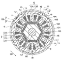
本発明の実施の形態1の電動機100について説明する。図1は、本発明の実施の形態1における電動機100の構成を示す断面図である。この電動機100は、回転子2に永久磁石25が埋め込まれた永久磁石埋込型電動機であり、例えばロータリ圧縮機500(図26参照)に用いられる。
Embodiment 1 FIG.
<Structure of electric motor>
The electric motor 100 according to Embodiment 1 of the present invention will be described. FIG. 1 is a cross-sectional view illustrating a configuration of electric motor 100 according to Embodiment 1 of the present invention. The electric motor 100 is a permanent magnet embedded type electric motor in which a permanent magnet 25 is embedded in a rotor 2, and is used, for example, in a rotary compressor 500 (see FIG. 26).

電動機100は、インナーロータ型と呼ばれる電動機であり、固定子1と、固定子1の内側に回転可能に設けられた回転子2とを有する。固定子1と回転子2との間には、例えば0.3〜1.0mmのエアギャップが形成されている。なお、図1は、回転子2の回転軸(軸線C1)に直交する面における断面図である。   The electric motor 100 is an electric motor called an inner rotor type, and includes a stator 1 and a rotor 2 rotatably provided inside the stator 1. An air gap of, for example, 0.3 to 1.0 mm is formed between the stator 1 and the rotor 2. FIG. 1 is a cross-sectional view in a plane orthogonal to the rotation axis (axis C1) of the rotor 2.

以下では、回転子2の回転軸である軸線C1の方向を、単に「軸方向」と称する。また。軸線C1を中心とする周方向を、単に「周方向」と称する。また、軸線C1を中心とする固定子1および回転子2の半径方向を、単に「径方向」と称する。他の図においても、矢印C1は軸方向を示し、矢印R1は周方向を示す。   Hereinafter, the direction of the axis C1 that is the rotation axis of the rotor 2 is simply referred to as “axial direction”. Also. A circumferential direction around the axis C1 is simply referred to as a “circumferential direction”. The radial direction of the stator 1 and the rotor 2 about the axis C1 is simply referred to as “radial direction”. Also in the other figures, the arrow C1 indicates the axial direction, and the arrow R1 indicates the circumferential direction.

固定子1は、固定子鉄心10と、固定子鉄心10に巻き付けられた巻線3とを有する。固定子鉄心10は、第1の鉄心10Aおよび第2の鉄心10B(図3)を有するが、これについては後述する。   The stator 1 has a stator core 10 and windings 3 wound around the stator core 10. The stator core 10 has a first core 10A and a second core 10B (FIG. 3), which will be described later.

固定子鉄心10は、軸線C1を中心とする環状のヨーク12と、ヨーク12から径方向内側(すなわち軸線C1に向かう方向)に延在する複数のティース11とを有している。ティース11の径方向内側の端部には、回転子2の外周面に対向するティース先端部13が形成されている。ティース先端部13は、幅(周方向の長さ)がティース11の他の部分よりも広く形成されている。すなわち、ティース先端部13は、周方向の両側に突出する突出部14を有している。   The stator core 10 has an annular yoke 12 centered on the axis C1, and a plurality of teeth 11 extending radially inward from the yoke 12 (that is, in a direction toward the axis C1). At a radially inner end of the tooth 11, a tooth tip 13 facing the outer peripheral surface of the rotor 2 is formed. The tooth tip 13 has a width (length in the circumferential direction) wider than other portions of the tooth 11. That is, the tooth tip 13 has the protrusions 14 protruding on both sides in the circumferential direction.

ここでは、9つのティース11が周方向に一定間隔で配置されているが、ティース11の数は2以上であればよい。周方向に隣り合うティース11の間には、巻線3を配置する空間であるスロットが形成される。   Here, nine teeth 11 are arranged at regular intervals in the circumferential direction, but the number of teeth 11 may be two or more. A slot, which is a space in which the windings 3 are arranged, is formed between the teeth 11 that are adjacent in the circumferential direction.

また、固定子鉄心10は、ティース11毎に複数(ここでは9つ)の分割コア5が周方向に連結された構成を有している。分割コア5は、ヨーク12の外周側の端部に設けられた連結部15で互いに連結されている。連結部15は、例えば、塑性変形可能な薄肉部で形成されている。   Further, the stator core 10 has a configuration in which a plurality of (here, nine) divided cores 5 are connected in the circumferential direction for each tooth 11. The split cores 5 are connected to each other at a connecting portion 15 provided at an outer peripheral end of the yoke 12. The connecting portion 15 is formed of, for example, a plastically deformable thin portion.

回転磁界を発生させる巻線3は、例えばマグネットワイヤを、絶縁部であるインシュレータ30(図2)を介してティース11に巻き付けたものである。巻線3の巻き数および直径(線径)は、要求される特性(回転数、トルク等)、印加電圧およびスロットの断面積に応じて決定される。巻線3は、集中巻きで巻かれ、Y結線により結線されている。   The winding 3 for generating a rotating magnetic field is formed, for example, by winding a magnet wire around the teeth 11 via an insulator 30 (FIG. 2) as an insulating portion. The number of turns and the diameter (wire diameter) of the winding 3 are determined according to required characteristics (rotational speed, torque, etc.), applied voltage and slot cross-sectional area. The winding 3 is wound by concentrated winding and connected by Y connection.

回転子2は、円筒状の回転子鉄心21と、回転子鉄心21に取り付けられた永久磁石25と、回転子鉄心21の中央部に配置されたシャフト60とを有する。シャフト60は、例えば、ロータリ圧縮機500(図26)のシャフトである。回転子鉄心21は、複数の電磁鋼板を軸方向に積層し、その軸方向の両端部を固定部材41,42(図3)で締結したものである。回転子鉄心21を構成する電磁鋼板の厚さtrは、例えば0.1〜0.7mmである。   The rotor 2 has a cylindrical rotor core 21, a permanent magnet 25 attached to the rotor core 21, and a shaft 60 arranged at the center of the rotor core 21. The shaft 60 is, for example, the shaft of the rotary compressor 500 (FIG. 26). The rotor core 21 is formed by laminating a plurality of electromagnetic steel plates in the axial direction, and fastening both ends in the axial direction of the magnetic steel plates with fixing members 41 and 42 (FIG. 3). The thickness tr of the electromagnetic steel sheet forming the rotor core 21 is, for example, 0.1 to 0.7 mm.

回転子鉄心21の外周面に沿って、永久磁石25が挿入される複数(ここでは6つ)の磁石挿入孔22が形成されている。磁石挿入孔22は、回転子鉄心21を軸方向に貫通する貫通孔である。磁石挿入孔22の数(すなわち磁極数)は6に限らず、2以上であればよい。隣り合う磁石挿入孔22の間は、極間となる。   A plurality (here, six) of magnet insertion holes 22 into which the permanent magnets 25 are inserted are formed along the outer peripheral surface of the rotor core 21. The magnet insertion hole 22 is a through hole that penetrates the rotor core 21 in the axial direction. The number of magnet insertion holes 22 (that is, the number of magnetic poles) is not limited to six, and may be two or more. The space between adjacent magnet insertion holes 22 is a gap.

永久磁石25は、軸方向に長い平板状の部材であり、回転子鉄心21の周方向に幅を有し、径方向に厚さを有している。永久磁石25の厚さは、例えば2mmである。永久磁石25は、例えば、ネオジウム(Nd)、鉄(Fe)およびボロン(B)を主成分とする希土類磁石で構成されている。永久磁石25は、厚さ方向に着磁されている。   The permanent magnet 25 is a plate-shaped member that is long in the axial direction, has a width in the circumferential direction of the rotor core 21, and has a thickness in the radial direction. The thickness of the permanent magnet 25 is, for example, 2 mm. The permanent magnet 25 is made of, for example, a rare earth magnet mainly containing neodymium (Nd), iron (Fe), and boron (B). The permanent magnet 25 is magnetized in the thickness direction.

ここでは、1つの磁石挿入孔22に1つの永久磁石25を配置しているが、1つの磁石挿入孔22に複数の永久磁石25を周方向に並べて配置してもよい。この場合、同じ磁石挿入孔22内の複数の永久磁石25は、互いに同一の極が径方向外側を向くように着磁される。   Here, one permanent magnet 25 is arranged in one magnet insertion hole 22, but a plurality of permanent magnets 25 may be arranged in one magnet insertion hole 22 in the circumferential direction. In this case, the plurality of permanent magnets 25 in the same magnet insertion hole 22 are magnetized such that the same poles face outward in the radial direction.

磁石挿入孔22の周方向両端部には、フラックスバリア(漏れ磁束抑制穴)23が形成されている。フラックスバリア23は、隣り合う永久磁石25の間の漏れ磁束を抑制するものである。フラックスバリア23と回転子鉄心21の外周との間の鉄心部分は、隣り合う永久磁石25の間の磁束の短絡を抑制するため、薄肉部となっている。薄肉部の厚さは、回転子鉄心21を構成する電磁鋼板の厚さと同じであることが望ましい。   Flux barriers (leakage flux suppressing holes) 23 are formed at both circumferential ends of the magnet insertion hole 22. The flux barrier 23 suppresses leakage magnetic flux between the adjacent permanent magnets 25. The core portion between the flux barrier 23 and the outer periphery of the rotor core 21 is a thin portion in order to suppress a short circuit of the magnetic flux between the adjacent permanent magnets 25. The thickness of the thin portion is desirably the same as the thickness of the electromagnetic steel sheet forming the rotor core 21.

図2は、電動機100の構成を示す、軸線C1を含む面における断面図である。固定子鉄心10は、電磁鋼板の積層体で構成される第1の鉄心10Aと、アモルファス金属またはナノ結晶金属の薄帯の積層体で構成される第2の鉄心10Bとを有している。第1の鉄心10Aおよび第2の鉄心10Bは、軸方向(軸線C1の方向)に交互に配置されている。特に、固定子鉄心10の少なくとも軸方向の両端部に、第1の鉄心10Aが配置されている。   FIG. 2 is a cross-sectional view showing a configuration of the electric motor 100 in a plane including the axis C1. The stator core 10 has a first iron core 10A formed of a laminated body of electromagnetic steel sheets, and a second iron core 10B formed of a thin laminated body of an amorphous metal or a nanocrystalline metal. The first iron core 10A and the second iron core 10B are alternately arranged in the axial direction (the direction of the axis C1). In particular, the first core 10 </ b> A is arranged at least at both ends in the axial direction of the stator core 10.

ここでは、固定子鉄心10の軸方向の両端部と中央部に、第1の鉄心10Aがそれぞれ配置されている。そして、軸方向に隣り合う第1の鉄心10Aに挟み込まれるように、第2の鉄心10Bが配置されている。   Here, the first cores 10A are arranged at both ends and the center of the stator core 10 in the axial direction, respectively. The second iron core 10B is disposed so as to be sandwiched between the first iron cores 10A adjacent in the axial direction.

固定子鉄心10の軸方向一端部(図2における上端部)に配置される第1の鉄心10Aの厚さ(軸方向の長さ)をL1とし、これに隣接する第2の鉄心10Bの厚さをL2とする。固定子鉄心10の軸方向中央に配置される第1の鉄心10Aの厚さをL3とし、これに隣接する第2の鉄心10Bの厚さをL4とし、固定子鉄心10の軸方向他端部(図3における下端部)に配置される第1の鉄心10Aの厚さをL5とする。   The thickness (length in the axial direction) of the first iron core 10A disposed at one axial end (the upper end in FIG. 2) of the stator core 10 is L1, and the thickness of the second iron core 10B adjacent thereto is L1. Is L2. The thickness of the first iron core 10A disposed at the axial center of the stator core 10 is L3, the thickness of the second iron core 10B adjacent to the first iron core 10B is L4, and the other end of the stator iron core 10 in the axial direction is L3. The thickness of the first iron core 10A disposed at (the lower end in FIG. 3) is L5.

第1の鉄心10Aの厚さの合計(=L1+L3+L5)は、第2の鉄心10Bの厚さ(=L2+L4)の合計よりも小さい。回転子2の永久磁石25からの磁束が第2の鉄心10Bに流れやすくするためである。なお、第1の鉄心10Aの厚さと第2の鉄心10Bの厚さの合計L0は、ここでは回転子鉄心21の軸方向の長さL6と同じであるが、必ずしも同じである必要は無い(後述する図12参照)。   The sum of the thicknesses of the first cores 10A (= L1 + L3 + L5) is smaller than the sum of the thicknesses of the second cores 10B (= L2 + L4). This is to make it easier for the magnetic flux from the permanent magnet 25 of the rotor 2 to flow to the second iron core 10B. In addition, the total L0 of the thickness of the first core 10A and the thickness of the second core 10B is the same as the axial length L6 of the rotor core 21 here, but is not necessarily required to be the same ( (See FIG. 12 described later.)

固定子鉄心10のうち、第1の鉄心10Aは、第2の鉄心10Bよりも径方向外側に突出している。第1の鉄心10Aは、電動機100の円筒状のフレーム6の内側に、焼き嵌め、圧入または溶接等によって組み込まれている。このフレーム6は、例えば、ロータリ圧縮機500(図26)の密閉容器の一部である。   Of the stator cores 10, the first core 10A projects radially outward from the second core 10B. The first iron core 10 </ b> A is incorporated inside the cylindrical frame 6 of the electric motor 100 by shrink fitting, press fitting, welding, or the like. The frame 6 is, for example, a part of a closed container of the rotary compressor 500 (FIG. 26).

図3は、第1の鉄心10Aを示す平面図である。第1の鉄心10Aは、厚さ(t1)が0.35〜1.00mmの電磁鋼板を軸方向に積層した積層体で構成される。電磁鋼板としては、例えば無方向性電磁鋼板が用いられるが、これに限定されるものではない。   FIG. 3 is a plan view showing the first iron core 10A. The first iron core 10A is formed of a laminate in which electromagnetic steel sheets having a thickness (t1) of 0.35 to 1.00 mm are laminated in the axial direction. As the magnetic steel sheet, for example, a non-oriented magnetic steel sheet is used, but it is not limited to this.

第1の鉄心10Aは、周方向に延在するヨーク12A(第1のヨーク)と、ヨーク12Aから径方向内側に延在する複数のティース11A(第1のティース)とを有している。ヨーク12Aは、フレーム6(図2)の内周面に当接する外周面16Aを有している。ティース11Aの数は、ここでは9つである。   The first iron core 10A has a yoke 12A (first yoke) extending in the circumferential direction, and a plurality of teeth 11A (first teeth) extending radially inward from the yoke 12A. The yoke 12A has an outer peripheral surface 16A that contacts the inner peripheral surface of the frame 6 (FIG. 2). Here, the number of the teeth 11A is nine.

第1の鉄心10Aのうち、分割コア5に相当する部分(それぞれ1つのティース11Aを含む部分)を、第1の分割鉄心部5Aと称する。すなわち、第1の鉄心10Aは、周方向に複数(ここでは9つ)の第1の分割鉄心部5Aに分割されている。   In the first core 10A, a portion corresponding to the split core 5 (a portion including one tooth 11A) is referred to as a first split core portion 5A. That is, the first core 10A is divided into a plurality (here, nine) of the first divided core portions 5A in the circumferential direction.

ヨーク12Aの外周側の端部には、例えば薄肉部で構成された連結部15が形成されている。連結部15は、それぞれの第1の分割鉄心部5Aの周方向の一端部に配置されている。連結部15は、周方向に隣り合う第1の分割鉄心部5Aを互いに連結する部分である。   At an end on the outer peripheral side of the yoke 12A, a connecting portion 15 formed of, for example, a thin portion is formed. The connecting portion 15 is disposed at one circumferential end of each of the first split core portions 5A. The connecting portion 15 is a portion that connects the first divided core portions 5A adjacent to each other in the circumferential direction.

この構成により、第1の鉄心10Aを構成する複数の第1の分割鉄心部5Aは、連結部15を中心として回動可能に連結される。すなわち、第1の鉄心10Aを帯状に展開し(図8参照)、また環状に組み合わせることができる。連結部15は、ここでは、塑性変形可能な薄肉部であるが、薄肉部に限らず、例えば円形のカシメ部であってもよい。   With this configuration, the plurality of first divided core portions 5A that constitute the first core 10A are rotatably connected around the connection portion 15. That is, the first iron core 10A can be developed in a belt shape (see FIG. 8) and can be combined in an annular shape. Here, the connecting portion 15 is a thin portion that can be plastically deformed, but is not limited to the thin portion, and may be, for example, a circular caulked portion.

図4は、第1の分割鉄心部5A(第1の鉄心10A)を示す平面図である。第1の分割鉄心部5Aでは、ヨーク12Aの周方向の中央部がティース11Aと連続している。ティース11Aの径方向内側には、回転子2の外周面に対向するティース先端部13Aが形成されている。ティース先端部13Aは、ティース11Aの他の部分よりも幅が広く、周方向の両側に突出部14A(第1の突出部)を有している。   FIG. 4 is a plan view showing the first split core part 5A (first core 10A). In the first split core portion 5A, the circumferential central portion of the yoke 12A is continuous with the teeth 11A. A tooth tip 13A facing the outer peripheral surface of the rotor 2 is formed radially inward of the tooth 11A. The tooth tip 13A is wider than the other parts of the tooth 11A, and has protrusions 14A (first protrusions) on both sides in the circumferential direction.

また、第1の分割鉄心部5Aでは、ヨーク12Aが、周方向の一端をなす端面17Aと、周方向の他端をなす端面18Aとを有している。なお、上記の連結部15は、外周面16Aと端面18Aとの間に形成されている。端面17A,18Aは、分割面に相当する。   In the first split core part 5A, the yoke 12A has an end face 17A forming one end in the circumferential direction and an end face 18A forming the other end in the circumferential direction. The connecting portion 15 is formed between the outer peripheral surface 16A and the end surface 18A. The end faces 17A and 18A correspond to division surfaces.

第1の鉄心10Aを図3に示したように環状に組み合わせると、第1の分割鉄心部5Aのヨーク12Aの端面17A,18Aは、それぞれ、周方向に隣接する第1の分割鉄心部5Aのヨーク12Aの端面18A,17Aに当接する。   When the first cores 10A are combined in an annular shape as shown in FIG. 3, the end faces 17A and 18A of the yoke 12A of the first split core 5A are respectively connected to the first split cores 5A adjacent in the circumferential direction. It comes into contact with the end surfaces 18A and 17A of the yoke 12A.

端面17A,18Aは、ヨーク12Aの内周面から外周面16Aに向けて径方向外側に延在するが、外周面16Aには到達しない。端面18Aの終端(すなわち径方向外側の端部)には、穴105が形成されている。ヨーク12Aの穴105と外周面16Aとの間の薄肉部は塑性変形可能な部分であり、この薄肉部が連結部15を構成する。   The end surfaces 17A and 18A extend radially outward from the inner peripheral surface of the yoke 12A toward the outer peripheral surface 16A, but do not reach the outer peripheral surface 16A. A hole 105 is formed at the end of the end face 18A (that is, at the outer end in the radial direction). The thin portion between the hole 105 of the yoke 12A and the outer peripheral surface 16A is a portion that can be plastically deformed, and this thin portion constitutes the connecting portion 15.

ヨーク12Aの外周面16Aには、凹部(切り欠き部)19が形成されている。凹部19は、後述する巻線工程(図9)において、固定子1を治具でチャックする部分である。   A concave portion (notch portion) 19 is formed on the outer peripheral surface 16A of the yoke 12A. The concave portion 19 is a portion where the stator 1 is chucked with a jig in a later-described winding step (FIG. 9).

ティース11Aの径方向の中央部には、カシメ部(ティースカシメ部)101が形成されている。ヨーク12Aの凹部19の周方向の両側には、カシメ部(ヨークカシメ部)102,103が形成されている。   A caulking portion (teeth caulking portion) 101 is formed at the radial center of the tooth 11A. On both sides in the circumferential direction of the concave portion 19 of the yoke 12A, caulked portions (yoke caulked portions) 102 and 103 are formed.

ティース11のカシメ部101およびヨーク12のカシメ部102,103は、軸方向に隣り合う電磁鋼板を互いに固定するものである。ティース11のカシメ部101およびヨーク12のカシメ部102,103で電磁鋼板を固定することにより、第1の鉄心10A(ティース11Aおよびヨーク12A)の高い寸法精度および高い剛性が得られる。   The caulked portion 101 of the tooth 11 and the caulked portions 102 and 103 of the yoke 12 are for fixing the electromagnetic steel sheets adjacent in the axial direction to each other. By fixing the electromagnetic steel plate at the caulked portion 101 of the tooth 11 and the caulked portions 102 and 103 of the yoke 12, high dimensional accuracy and high rigidity of the first iron core 10A (the tooth 11A and the yoke 12A) can be obtained.

なお、カシメ部101は、ティース11Aの中央部に限らず、例えば、ティース先端部13の周方向両端部、あるいはティース先端部13の周方向中央部に設けてもよい。   The caulking portion 101 is not limited to the central portion of the tooth 11A, and may be provided, for example, at both ends of the tooth tip 13 in the circumferential direction or at the central portion of the tooth tip 13 in the circumferential direction.

図5は、第2の鉄心10Bの構成を示す平面図である。第2の鉄心10Bは、アモルファス金属またはナノ結晶金属で構成されている。また、第2の鉄心10Bは、厚さが0.02mm〜0.05mmの薄帯を軸方向に積層した積層体で構成されている。第2の鉄心10Bは、接着剤または樹脂によって第1の鉄心10A(図3)に固定される。   FIG. 5 is a plan view showing the configuration of the second iron core 10B. The second iron core 10B is made of an amorphous metal or a nanocrystalline metal. The second iron core 10B is formed of a laminate in which thin ribbons having a thickness of 0.02 mm to 0.05 mm are laminated in the axial direction. Second iron core 10B is fixed to first iron core 10A (FIG. 3) by an adhesive or a resin.

アモルファス金属またはナノ結晶金属の薄帯を積層する場合には、電磁鋼板のようなカシメ部による固定は難しいため、積層する薄帯の間に接着剤を供給することで、複数の薄帯を互いに固定する。この場合、積層される薄帯の間に接着剤が介在するため、渦電流損を抑制する効果も得られる。   When laminating ribbons of amorphous metal or nanocrystalline metal, it is difficult to fix them by caulking parts such as electromagnetic steel sheets. Fix it. In this case, since the adhesive is interposed between the laminated ribbons, an effect of suppressing eddy current loss can be obtained.

なお、第2の鉄心10Bを、アモルファス金属の薄帯の積層体によって形成する場合、成形時に生じた歪の除去と磁気特性の向上のため、第2の鉄心10Bを焼鈍してもよい。   When the second core 10B is formed of a laminate of amorphous metal ribbons, the second core 10B may be annealed in order to remove distortion generated during molding and improve magnetic properties.

また、第2の鉄心10Bは、アモルファス金属またはナノ結晶金属の薄帯の積層体に限らず、アモルファス金属またはナノ結晶金属の粉体の圧縮成形体(図12参照)で構成してもよい。   Further, the second iron core 10B is not limited to a laminate of amorphous metal or nanocrystalline metal ribbons, but may be formed of a compression molded body of amorphous metal or nanocrystalline metal powder (see FIG. 12).

第2の鉄心10Bは、周方向に延在するヨーク12B(第2のヨーク)と、ヨーク12Bから径方向内側に延在する複数のティース11B(第2のティース)とを有している。ヨーク12Bは、フレーム6(図3)の内周面に対向する外周面16Bを有している。ティース11Bの数は、ここでは9つである。   The second iron core 10B has a yoke 12B (second yoke) extending in the circumferential direction, and a plurality of teeth 11B (second teeth) extending radially inward from the yoke 12B. The yoke 12B has an outer peripheral surface 16B facing the inner peripheral surface of the frame 6 (FIG. 3). Here, the number of the teeth 11B is nine.

第2の鉄心10Bのうち、分割コア5に対応する部分(それぞれ1つのティース11Bを含む部分)を、第2の分割鉄心部5Bと称する。すなわち、第2の鉄心10Bは、周方向に複数(ここでは9つ)の第2の分割鉄心部5Bに分割されている。周方向に隣り合う第2の分割鉄心部5Bは、0.1mm以下の空隙Gによって互いに隔てられている。   In the second core 10B, a portion corresponding to the split core 5 (a portion including one tooth 11B) is referred to as a second split core 5B. That is, the second core 10B is divided into a plurality of (here, nine) second divided core portions 5B in the circumferential direction. The second divided core portions 5B adjacent in the circumferential direction are separated from each other by a gap G of 0.1 mm or less.

図6は、第2の分割鉄心部5B(第2の鉄心10B)を示す平面図である。第2の分割鉄心部5Bでは、ヨーク12Bの周方向の中央部がティース11Bと連続している。ティース11Bの径方向内側には、回転子2の外周面に対向するティース先端部13Bが形成されている。ティース先端部13Bは、ティース11Bの他の部分よりも幅が広く、周方向の両側に突出部14B(第2の突出部)を有している。   FIG. 6 is a plan view showing a second split core part 5B (second core 10B). In the second split core portion 5B, the central portion in the circumferential direction of the yoke 12B is continuous with the teeth 11B. A tooth tip 13B facing the outer peripheral surface of the rotor 2 is formed radially inward of the tooth 11B. The tooth tip 13B is wider than other portions of the tooth 11B, and has projections 14B (second projections) on both sides in the circumferential direction.

ヨーク12Bの外周面16Bは、ヨーク12Aの外周面16A(図4)よりも径方向内側に位置している。また、第2の分割鉄心部5Bにおけるヨーク12Bの周方向の端面17B,18Bは、第1の分割鉄心部5Aにおけるヨーク12Aの端面17A,18A(図4)よりも、それぞれ周方向内側に位置している。なお、第2の鉄心10Bのティース11Bおよびヨーク12Bには、第1の鉄心10Aのカシメ部101,102,103(図4(A))は設けられていない。   The outer peripheral surface 16B of the yoke 12B is located radially inward of the outer peripheral surface 16A (FIG. 4) of the yoke 12A. The circumferential end faces 17B and 18B of the yoke 12B in the second split core part 5B are located on the circumferential inner side than the end faces 17A and 18A (FIG. 4) of the yoke 12A in the first split core part 5A. are doing. The teeth 11B and the yoke 12B of the second core 10B are not provided with the swaging portions 101, 102, and 103 (FIG. 4A) of the first core 10A.

図7(A)は、分割コア5(第1の分割鉄心部5Aおよび第2の分割鉄心部5B)、インシュレータ30および巻線3を示す図である。図7(A)において、第1の分割鉄心部5Aのティース11Aの周方向の幅をT1とし、ヨーク12Aの径方向の幅をY1とする。また、第2の分割鉄心部5Bのティース11Bの周方向の幅をT2とし、ヨーク12Bの径方向の幅をY2とする。   FIG. 7A is a diagram illustrating the split core 5 (the first split core portion 5A and the second split core portion 5B), the insulator 30 and the winding 3. In FIG. 7A, the circumferential width of the teeth 11A of the first split core portion 5A is T1 and the radial width of the yoke 12A is Y1. Further, the circumferential width of the teeth 11B of the second divided core portion 5B is T2, and the radial width of the yoke 12B is Y2.

この実施の形態の固定子鉄心10は、ティース11Aの幅T1がティース11Bの幅T2よりも小さく(T1<T2)、または、ヨーク12Aの幅Y1がヨーク12Bの幅Y2よりも小さく(Y1<Y2)、若しくはその両方が成立するように構成されている。すなわち、第1の鉄心10Aは、第2の鉄心10Bよりも、磁路が狭くなるように構成されている。   In the stator core 10 of this embodiment, the width T1 of the teeth 11A is smaller than the width T2 of the teeth 11B (T1 <T2), or the width Y1 of the yoke 12A is smaller than the width Y2 of the yoke 12B (Y1 < Y2), or both. That is, the first iron core 10A is configured such that the magnetic path is narrower than the second iron core 10B.

なお、図7(A)に示した例では、ティース11Aの幅T1がティース11Bの幅T2よりも小さく、なお且つ、ヨーク12Aの幅Y1がヨーク12Bの幅Y2よりも小さい(すなわち、T1<T2、且つY1<Y2)。   In the example shown in FIG. 7A, the width T1 of the teeth 11A is smaller than the width T2 of the teeth 11B, and the width Y1 of the yoke 12A is smaller than the width Y2 of the yoke 12B (that is, T1 < T2, and Y1 <Y2).

加えて、ティース11Aの周方向の突出部14Aの径方向の幅をP1とし、ティース11Bの周方向の突出部14Bの径方向の幅をP2とする。ここでは、ティース11Aの突出部14Aの径方向の幅P1が、ティース11Bの突出部14Bの径方向の幅P2よりも小さい(P1<P2)。   In addition, the radial width of the circumferential protrusion 14A of the teeth 11A is P1 and the radial width of the circumferential protrusion 14B of the teeth 11B is P2. Here, the radial width P1 of the protruding portion 14A of the tooth 11A is smaller than the radial width P2 of the protruding portion 14B of the tooth 11B (P1 <P2).

また、ヨーク12Bの外周面16Bは、ヨーク12Aの外周面16Aに対して径方向内側に位置している。言い換えると、軸線C1からヨーク12Aの外周面16Aまでの距離r1(図3)は、軸線C1からヨーク12Bの外周面16B(図5)までの距離r2よりも大きい(r1>r2)。   The outer peripheral surface 16B of the yoke 12B is located radially inward of the outer peripheral surface 16A of the yoke 12A. In other words, the distance r1 from the axis C1 to the outer peripheral surface 16A of the yoke 12A (FIG. 3) is greater than the distance r2 from the axis C1 to the outer peripheral surface 16B of the yoke 12B (FIG. 5) (r1> r2).

ティース先端部13Aの径方向内側の端面(回転子2に対向する端面)は、ティース先端部13Bの径方向値側の端面と同一面上に位置している。但し、このような構成に限定されるものではなく、ティース先端部13Aの端面の方が回転子2から離間していてもよい(図14参照)。   The radially inner end face (the end face facing the rotor 2) of the tooth tip 13A is located on the same plane as the radial value side end face of the tooth tip 13B. However, the configuration is not limited to such a configuration, and the end surface of the tooth tip 13A may be separated from the rotor 2 (see FIG. 14).

ティース11(ティース11Aおよびティース11B)には、インシュレータ30を介して、巻線3が巻き付けられている。インシュレータ30は、ティース11の周方向の両側面111(より具体的にはティース11Bの側面111B)に形成された周壁部31と、ヨーク12の内周面121(より具体的にはヨーク12Bの内周面121B)に形成された外側壁部32と、突出部14の径方向外側の面に形成された内側壁部33とを有している。   The windings 3 are wound around the teeth 11 (the teeth 11A and the teeth 11B) via the insulator 30. The insulator 30 includes a peripheral wall portion 31 formed on both side surfaces 111 of the teeth 11 in the circumferential direction (more specifically, side surfaces 111B of the teeth 11B), and an inner peripheral surface 121 of the yoke 12 (more specifically, the yoke 12B). An outer wall portion 32 is formed on the inner peripheral surface 121B), and an inner wall portion 33 is formed on a radially outer surface of the protrusion 14.

インシュレータ30の周壁部31と外側壁部32と内側壁部33とで囲まれた領域に、巻線3が配置される。また、インシュレータ30の周壁部31は、ティース11の軸方向における両端面にも形成されている(図2参照)。各ティース11には、インシュレータ30を介して、例えば直径1.0mmのマグネットワイヤが80ターン巻き付けられ、巻線3を構成する。   The winding 3 is arranged in a region surrounded by the peripheral wall portion 31, the outer wall portion 32, and the inner wall portion 33 of the insulator 30. The peripheral wall portion 31 of the insulator 30 is also formed on both end surfaces of the teeth 11 in the axial direction (see FIG. 2). A magnet wire having a diameter of, for example, 1.0 mm is wound around each of the teeth 11 via the insulator 30 for 80 turns to form the winding 3.

上述したように、ティース11Aの幅T1がティース11Bの幅T2よりも小さく、ヨーク12Aの幅Y1がヨーク12Bの幅Y2よりも小さいため、ティース11Aの側面111Aおよびヨーク12Aの内周面121Aとインシュレータ30との間には、空隙Sが形成される。   As described above, since the width T1 of the teeth 11A is smaller than the width T2 of the teeth 11B and the width Y1 of the yoke 12A is smaller than the width Y2 of the yoke 12B, the side surface 111A of the teeth 11A and the inner peripheral surface 121A of the yoke 12A A gap S is formed between the insulator 30 and the insulator 30.

但し、図7(B)に示すように、ティース11Aの側面111Aおよびヨーク12Aの内周面121Aとインシュレータ30との間に、樹脂35を充填してもよい。このようにすれば、より強固にインシュレータ30を保持することができる。   However, as shown in FIG. 7B, the resin 35 may be filled between the insulator 30 and the side surface 111A of the teeth 11A and the inner peripheral surface 121A of the yoke 12A. By doing so, the insulator 30 can be more firmly held.

上記の通り、ヨーク12Bの外周面16Bは、ヨーク12Aの外周面16Aに対して径方向内側に位置している。そのため、図2に示すように、ヨーク12Aの外周面16Aはフレーム6に当接するが、ヨーク12Bの外周面16Bはフレーム6から離間している。従って、第1の鉄心10Aにはフレーム6からの外力が作用するが、第2の鉄心10Bにはフレーム6からの外力は作用しない。   As described above, the outer peripheral surface 16B of the yoke 12B is located radially inward of the outer peripheral surface 16A of the yoke 12A. Therefore, as shown in FIG. 2, the outer peripheral surface 16A of the yoke 12A contacts the frame 6, but the outer peripheral surface 16B of the yoke 12B is separated from the frame 6. Therefore, the external force from the frame 6 acts on the first core 10A, but the external force from the frame 6 does not act on the second iron core 10B.

また、第2の分割鉄心部5Bにおけるヨーク12Bの端面17B,18B(図4)は、第1の分割鉄心部5Aにおけるヨーク12Aの端面17A,18A(図6)よりもそれぞれ周方向内側に位置している。そのため、周方向に隣り合う第2の分割鉄心部5Bの間には、空隙G(図5)が形成される。従って、第2の分割鉄心部5Bには、隣接する第2の分割鉄心部5Bからの外力が作用しない。   Further, the end faces 17B, 18B of the yoke 12B in the second split core part 5B (FIG. 4) are respectively located inward in the circumferential direction from the end faces 17A, 18A (FIG. 6) of the yoke 12A in the first split core part 5A. are doing. Therefore, a gap G (FIG. 5) is formed between the second divided core portions 5B adjacent in the circumferential direction. Therefore, no external force from the adjacent second split core 5B acts on the second split core 5B.

なお、第1の鉄心10Aは、ヨーク12Aの外周側の連結部15で連結された複数の第1の分割鉄心部5Aに分割されている。これに対し、第2の鉄心10Bは、空隙Gを介して互いに離間した複数の第2の分割鉄心部5Bに分割されている。   The first core 10A is divided into a plurality of first divided core portions 5A connected by a connection portion 15 on the outer peripheral side of the yoke 12A. On the other hand, the second core 10B is divided into a plurality of second divided core portions 5B separated from each other via the gap G.

<電動機の製造工程>
次に、電動機100の製造工程について説明する。まず、電磁鋼板から、ティース11Aとヨーク12Aとを有する形状の複数の鋼板部分を打ち抜く。ここでは、図8に示したように帯状につながった鋼板部分が打ち抜かれる。次に、打ち抜かれた鋼板部分を軸方向に複数枚積層し、カシメ部101,102,103で互いに固定する。
<Electric motor manufacturing process>
Next, the manufacturing process of the electric motor 100 will be described. First, a plurality of steel plate portions each having a shape including the teeth 11A and the yoke 12A are punched from an electromagnetic steel plate. Here, as shown in FIG. 8, a steel plate portion connected in a strip shape is punched. Next, a plurality of punched steel plate portions are laminated in the axial direction, and are fixed to each other by caulking portions 101, 102, and 103.

また、アモルファス金属またはナノ結晶金属の薄帯から、ティース11Bとヨーク12Bとを有する形状の複数の薄帯部分を打ち抜く。次に、打ち抜かれた薄帯部分を軸方向に複数枚積層し、接着により互いに固定することにより、図6に示した第2の分割鉄心部5Bを形成する。そして、複数の第2の分割鉄心部5Bを、第1の鉄心10A(図8)に固定する。これにより、分割コア5を帯状に配列した固定子鉄心10が形成される。   In addition, a plurality of thin ribbon portions each having a tooth 11B and a yoke 12B are punched from a thin ribbon of an amorphous metal or a nanocrystalline metal. Next, a plurality of punched thin ribbon portions are laminated in the axial direction and fixed to each other by bonding to form the second split core portion 5B shown in FIG. Then, the plurality of second divided core portions 5B are fixed to the first core 10A (FIG. 8). Thereby, the stator core 10 in which the divided cores 5 are arranged in a strip shape is formed.

次に、固定子鉄心10にインシュレータ30(図7)を形成する。インシュレータ30は、例えば、固定子鉄心10を金型内にセットして樹脂を充填することにより固定子鉄心10と一体に成形してもよく、あるいは、予め成型した樹脂成型体を固定子鉄心10に嵌め込んで形成してもよい。   Next, the insulator 30 (FIG. 7) is formed on the stator core 10. The insulator 30 may be formed integrally with the stator core 10 by, for example, setting the stator core 10 in a mold and filling a resin, or a pre-molded resin molded body may be used as the stator core 10. It may be formed by being fitted into a.

固定子鉄心10にインシュレータ30を形成したのち、巻線を行う。図9(A)および(B)は、巻線工程を説明するための模式図である。まず、図9(B)に示すように、複数の分割コア5を帯状に配列した固定子鉄心10のうち、巻線を行う分割コア5を巻線位置に治具で固定し、その両側の分割コア5を、隣り合うティース11の間隔が広がるように、連結部15を中心として回動させる。これにより、巻線を行うティース11の周囲に広い空間を形成する。   After forming the insulator 30 in the stator core 10, winding is performed. FIGS. 9A and 9B are schematic diagrams for explaining a winding step. First, as shown in FIG. 9 (B), among the stator cores 10 in which a plurality of divided cores 5 are arranged in a belt shape, the divided cores 5 for performing winding are fixed at the winding positions with jigs. The split core 5 is rotated about the connecting portion 15 so that the interval between the adjacent teeth 11 is increased. Thereby, a wide space is formed around the teeth 11 for winding.

この状態で、巻線位置に固定した分割コア5のティース11の周囲に、巻線装置の巻線ノズル7を用いて巻線3を巻き付ける。巻線ノズル7は、図9(B)に矢印R2で示すようにティース11の周囲を回転し、ティース11の周囲に巻線3を巻き付ける。   In this state, the winding 3 is wound around the teeth 11 of the split core 5 fixed at the winding position using the winding nozzle 7 of the winding device. The winding nozzle 7 rotates around the tooth 11 as indicated by an arrow R2 in FIG. 9B, and winds the winding 3 around the tooth 11.

各ティース11に巻線3を巻き付けたのち、図9(A)に示すように、固定子鉄心10を環状に組み立てる。このとき、固定子鉄心10の両端の分割コア5の突き合わせ部(図1に符号Wで示す)を互いに突き合わせ、溶接する。   After winding the winding 3 around each tooth 11, the stator core 10 is assembled in a ring shape as shown in FIG. 9 (A). At this time, the butting portions (indicated by W in FIG. 1) of the split cores 5 at both ends of the stator core 10 are butted and welded to each other.

これにより、固定子鉄心10とインシュレータ30と巻線3とを備えた固定子1が完成する。その後、固定子1をフレーム6の内側に、焼き嵌め、圧入、または溶接によって組み込む。上述したように、固定子鉄心10のうち、第1の鉄心10Aはフレーム6に当接するが、第2の鉄心10Bはフレーム6に当接しない。   Thus, the stator 1 including the stator core 10, the insulator 30, and the windings 3 is completed. Thereafter, the stator 1 is assembled into the frame 6 by shrink fitting, press fitting, or welding. As described above, among the stator cores 10, the first core 10A contacts the frame 6, but the second core 10B does not contact the frame 6.

また、電磁鋼板から、磁石挿入孔22、フラックスバリア23および中心孔26を有する回転子鉄心21の形状を有する鋼板部分を打ち抜く。次に、打ち抜かれた鋼板部分を軸方向に複数枚積層し、固定部材41,42(図2)で軸方向両側から固定することにより、図2に示した回転子鉄心21を形成する。   Further, a steel plate portion having the shape of the rotor core 21 having the magnet insertion hole 22, the flux barrier 23 and the center hole 26 is punched from the electromagnetic steel plate. Next, a plurality of punched steel plates are laminated in the axial direction, and fixed from both sides in the axial direction by fixing members 41 and 42 (FIG. 2), thereby forming the rotor core 21 shown in FIG.

さらに、回転子鉄心21の磁石挿入孔22に永久磁石25を挿入し、中心孔26にシャフト60を挿入することにより、回転子2を形成する。その後、回転子2を、フレーム6内に取り付けられた固定子1の内側に挿入する。これにより、図1に示した電動機100が完成する。   Further, the rotor 2 is formed by inserting the permanent magnet 25 into the magnet insertion hole 22 of the rotor core 21 and inserting the shaft 60 into the center hole 26. Thereafter, the rotor 2 is inserted inside the stator 1 mounted in the frame 6. Thereby, the electric motor 100 shown in FIG. 1 is completed.

<固定子の作用>
図10は、この実施の形態の固定子1の作用を説明するための断面図である。上記の通り、固定子鉄心10のうち、電磁鋼板で構成された第1の鉄心10Aは、焼き嵌め、圧入または溶接等によって、フレーム6の内側に固定されている。一方、アモルファス金属またはナノ結晶金属で構成された第2の鉄心10Bは、フレーム6から離間している。
<Operation of stator>
FIG. 10 is a cross-sectional view for explaining the operation of the stator 1 of this embodiment. As described above, of the stator core 10, the first iron core 10A made of an electromagnetic steel plate is fixed to the inside of the frame 6 by shrink fitting, press fitting, welding, or the like. On the other hand, the second iron core 10 </ b> B made of an amorphous metal or a nanocrystalline metal is separated from the frame 6.

固定子鉄心10(第1の鉄心10Aおよび第2の鉄心10B)は、回転子2の外周面に対向している。回転子2の永久磁石25からの磁束は、ティース先端部13(図1)からティース11に流入し、ティース11内を径方向外側に向かって流れる。ティース11内を流れた磁束は、ヨーク12に流入し、さらにヨーク12内を周方向に流れる。このようにして、ティース11およびヨーク12を通る磁束の通路(磁路)が形成され、磁束と巻線3を流れる電流との作用により、回転子2を回転させるトルクが発生する。   The stator core 10 (the first core 10A and the second core 10B) faces the outer peripheral surface of the rotor 2. The magnetic flux from the permanent magnet 25 of the rotor 2 flows into the tooth 11 from the tooth tip 13 (FIG. 1), and flows inside the tooth 11 radially outward. The magnetic flux flowing in the teeth 11 flows into the yoke 12 and further flows in the yoke 12 in the circumferential direction. In this manner, a magnetic flux path (magnetic path) passing through the teeth 11 and the yoke 12 is formed, and a torque for rotating the rotor 2 is generated by the action of the magnetic flux and the current flowing through the winding 3.

ティース11を構成するティース11A,11Bのうち、ティース11Aの幅T1はティース11Bの幅T2よりも小さい(T1<T2)。また、ティース11Aの突出部14Aの幅P1は、ティース11Bの突出部14Bの幅P2よりも小さい(P1<P2)。そのため、回転子2の永久磁石25からの磁束は、ティース11Aよりもティース11Bに流入しやすい。   Of the teeth 11A and 11B constituting the tooth 11, the width T1 of the tooth 11A is smaller than the width T2 of the tooth 11B (T1 <T2). The width P1 of the protrusion 14A of the tooth 11A is smaller than the width P2 of the protrusion 14B of the tooth 11B (P1 <P2). Therefore, the magnetic flux from the permanent magnet 25 of the rotor 2 flows into the teeth 11B more easily than the teeth 11A.

第2の鉄心10Bはアモルファス金属またはナノ結晶金属で構成されているが、アモルファス金属は原子が非晶質で方向性を持たず、ナノ結晶金属は結晶粒が10μmオーダーまで微細化されているため、いずれも磁気特性に優れ、磁気抵抗が小さい。そのため、回転子2の永久磁石25からの磁束がティース11Aよりもティース11Bに多く流れることで、鉄損が減少する。   The second iron core 10B is made of an amorphous metal or a nanocrystalline metal. However, since the amorphous metal has atoms which are amorphous and has no directionality, and the crystal grains of the nanocrystalline metal are refined to the order of 10 μm. , All have excellent magnetic properties and low magnetic resistance. Therefore, more magnetic flux from the permanent magnet 25 of the rotor 2 flows to the teeth 11B than to the teeth 11A, so that iron loss is reduced.

また、ティース11を流れた磁束は、その外周側のヨーク12に流入する。ヨーク12を構成するヨーク12A,12Bのうち、ヨーク12Aの幅Y1は、ヨーク12Bの幅Y2よりも小さいため(Y1<Y2)、磁束はヨーク12Aよりもヨーク12Bに多く流れ、これにより鉄損が減少する。   The magnetic flux flowing through the teeth 11 flows into the yoke 12 on the outer peripheral side. Of the yokes 12A and 12B constituting the yoke 12, the width Y1 of the yoke 12A is smaller than the width Y2 of the yoke 12B (Y1 <Y2), so that more magnetic flux flows to the yoke 12B than to the yoke 12A, thereby causing iron loss. Decrease.

加えて、第1の鉄心10Aの厚さの合計(図3に示したL1+L3+L5)は、第2の鉄心10Bの厚さの合計(L2+L4)よりも小さいため、ティース11Aが回転子2に対向する面積よりも、ティース11Bが回転子2に対向する面積の方が大きい。そのため、回転子2の永久磁石25からの磁束は、第1の鉄心10Aよりも第2の鉄心10Bに流れやすく、鉄損をさらに低減することができる。   In addition, since the sum of the thicknesses of the first cores 10A (L1 + L3 + L5 shown in FIG. 3) is smaller than the sum of the thicknesses of the second cores 10B (L2 + L4), the teeth 11A face the rotor 2. The area where the teeth 11B face the rotor 2 is larger than the area. Therefore, the magnetic flux from the permanent magnet 25 of the rotor 2 flows more easily to the second iron core 10B than to the first iron core 10A, and the iron loss can be further reduced.

さらに、第1の鉄心10Aを構成する電磁鋼板は、アモルファス金属ほど顕著ではないものの、圧縮応力を受けると磁気抵抗が増加する性質を有する。そのため、第1の鉄心10Aにフレーム6からの圧縮応力が加わると、回転子2の永久磁石25からの磁束が、第1の鉄心10Aには流れにくくなる。その結果、アモルファス金属またはナノ結晶金属で構成された(従って磁気抵抗が小さい)第2の鉄心10Bに流れる磁束が増加し、鉄損をさらに低減することができる。   Further, the electromagnetic steel sheet constituting the first iron core 10A has a property that the magnetic resistance increases when it is subjected to compressive stress, although it is not so remarkable as amorphous metal. Therefore, when compressive stress from the frame 6 is applied to the first iron core 10A, the magnetic flux from the permanent magnet 25 of the rotor 2 hardly flows to the first iron core 10A. As a result, the magnetic flux flowing through the second iron core 10B made of the amorphous metal or the nanocrystalline metal (therefore, the magnetic resistance is small) increases, and the iron loss can be further reduced.

第2の鉄心10Bを構成するアモルファス金属またはナノ結晶金属は、圧縮応力を受けた際の磁気抵抗の低下が、電磁鋼板よりも顕著である。しかしながら、第2の鉄心10Bは第1の鉄心10Aよりも外径が小さく、フレーム6に当接しないため、第2の鉄心10Bに加わる圧縮応力を抑制することができる。そのため、第2の鉄心10Bの磁気抵抗の増加を抑制することができる。   The amorphous metal or the nanocrystalline metal constituting the second iron core 10B has a more remarkable decrease in magnetic resistance when subjected to compressive stress than the electromagnetic steel sheet. However, since the second core 10B has a smaller outer diameter than the first core 10A and does not come into contact with the frame 6, the compressive stress applied to the second core 10B can be suppressed. Therefore, an increase in the magnetic resistance of second core 10B can be suppressed.

また、第2の鉄心10Bをアモルファス金属粉体の圧縮成形体で構成した場合には、第2の鉄心10Bの機械的強度が低下する可能性があるが、この実施の形態1では、第2の鉄心10Bがフレーム6に当接しないため、第2の鉄心10Bの損傷を抑制することができる。   Further, when the second iron core 10B is formed of a compression-molded body of amorphous metal powder, the mechanical strength of the second iron core 10B may decrease. The core 10B does not contact the frame 6, so that the damage to the second core 10B can be suppressed.

さらに、電磁鋼板で構成された第1の鉄心10A(ティース11Aおよびヨーク12A)によって第2の鉄心10B(ティース11Bおよびヨーク12B)を保持することができるため、固定子1の剛性を高めることができる。   Further, since the second iron core 10B (the teeth 11B and the yoke 12B) can be held by the first iron core 10A (the teeth 11A and the yoke 12A) made of an electromagnetic steel plate, the rigidity of the stator 1 can be increased. it can.

<実施の形態の効果>
以上説明したように、本発明の実施の形態1によれば、固定子鉄心10が、ティース11Aおよびヨーク12Aを有する第1の鉄心10Aと、ティース11Bおよびヨーク12Bを有する第2の鉄心10Bとを備える。第1の鉄心10Aは電磁鋼板の積層体で構成され、第2の鉄心10Bがアモルファス金属またはナノ結晶金属の薄帯の積層体、若しくはアモルファス金属の粉体またはナノ結晶金属の粉体の圧縮成形体で構成される。また、ティース11Aの幅T1、ティース11Bの幅T2、ヨーク12Aの幅Y1およびヨーク12Bの幅Y2の間に、T1<T2、Y1<Y2、またはその両方が成立する。そのため、回転子2の永久磁石25からの磁束が第2の鉄心10Bに流れやすくなり、鉄損を低減することができる。
<Effects of Embodiment>
As described above, according to Embodiment 1 of the present invention, stator core 10 includes first core 10A having teeth 11A and yoke 12A, and second core 10B having teeth 11B and yoke 12B. Is provided. The first iron core 10A is formed of a laminated body of electromagnetic steel sheets, and the second iron core 10B is formed of a thin laminated body of an amorphous metal or a nanocrystalline metal, or a compression molding of an amorphous metal powder or a nanocrystalline metal powder. It is composed of the body. In addition, T1 <T2, Y1 <Y2, or both are established between the width T1 of the teeth 11A, the width T2 of the teeth 11B, the width Y1 of the yoke 12A, and the width Y2 of the yoke 12B. Therefore, the magnetic flux from the permanent magnet 25 of the rotor 2 easily flows to the second iron core 10B, and the iron loss can be reduced.

また、第1の鉄心10A(ティース11Aおよびヨーク12A)によって第2の鉄心10B(ティース11Bおよびヨーク12B)を保持することができるため、固定子鉄心10の剛性を高めることができ、振動および騒音を抑制することができる。   Further, since the second iron core 10B (the teeth 11B and the yoke 12B) can be held by the first iron core 10A (the teeth 11A and the yoke 12A), the rigidity of the stator iron core 10 can be increased, and vibration and noise can be obtained. Can be suppressed.

さらに、ティース11Aの突出部14Aの幅P1がティース11Bの突出部14Bの幅P2よりも小さい(P1<P2)ため、回転子2の永久磁石25からの磁束は、ティース11Aよりもティース11Bに流入しやすい。そのため、鉄損を効果的に低減することができる。   Furthermore, since the width P1 of the protrusion 14A of the tooth 11A is smaller than the width P2 of the protrusion 14B of the tooth 11B (P1 <P2), the magnetic flux from the permanent magnet 25 of the rotor 2 is more concentrated on the tooth 11B than on the tooth 11A. Easy to flow. Therefore, iron loss can be effectively reduced.

また、アモルファス金属およびナノ結晶金属は、圧縮応力を受けると磁気抵抗が増加する性質を有するが、第2の鉄心10Bの外径が第1の鉄心10Aの外径よりも小さいため、固定子鉄心10をフレーム6に焼嵌め等によって組み込むと、フレーム6からの外力を第1の鉄心10Aで受けることができる。そのため、第2の鉄心10Bの磁気抵抗の増加を抑制することができ、鉄損を効果的に低減することができる。   The amorphous metal and the nanocrystalline metal have a property of increasing the magnetic resistance when subjected to a compressive stress. However, since the outer diameter of the second core 10B is smaller than the outer diameter of the first iron core 10A, the stator core When the frame 10 is assembled into the frame 6 by shrink fitting or the like, external force from the frame 6 can be received by the first iron core 10A. Therefore, an increase in the magnetic resistance of second core 10B can be suppressed, and iron loss can be effectively reduced.

また、第1の鉄心10Aの軸方向の長さ(厚さの合計)が、第2の鉄心10Bの軸方向の長さよりも小さいため、ティース11Aが回転子2に対向する面積よりも、ティース11Bが回転子2に対向する面積の方が大きくなる。その結果、回転子2の永久磁石25からの磁束が、固定子鉄心10のうち第2の鉄心10Bに流れやすくなり、鉄損を効果的に低減することができる。   Further, since the axial length (total thickness) of the first iron core 10A is smaller than the axial length of the second iron core 10B, the teeth 11A are smaller than the area of the teeth 11A facing the rotor 2. The area where 11B faces the rotor 2 is larger. As a result, the magnetic flux from the permanent magnet 25 of the rotor 2 easily flows to the second core 10B of the stator core 10, and iron loss can be effectively reduced.

また、第1の鉄心10Aが、固定子鉄心10の軸方向の両端部および中央部に配置されているため、固定子鉄心10の十分な強度を得ることができる。   Further, since the first iron core 10A is disposed at both ends and the center of the stator core 10 in the axial direction, sufficient strength of the stator core 10 can be obtained.

また、第1の鉄心10Aは、隣り合うティース11Aの間に形成された分割面(17A,18A)で複数に分割され、ヨーク12Aの外周面側の連結部15で連結されている。そのため、巻線工程において、連結部15を中心として分割コア5を回動させ、ティース11の周囲に広い空間を形成することができ、巻線工程が簡単になる。また、スロットの断面積に対して高密度の巻線が可能になり、高効率の電動機100が得られる。   Further, the first iron core 10A is divided into a plurality of parts by dividing surfaces (17A, 18A) formed between adjacent teeth 11A, and is connected by a connecting part 15 on the outer peripheral surface side of the yoke 12A. Therefore, in the winding process, the divided core 5 can be rotated around the connecting portion 15 to form a wide space around the teeth 11, thereby simplifying the winding process. In addition, high-density winding is possible with respect to the cross-sectional area of the slot, and the motor 100 with high efficiency is obtained.

また、第2の鉄心10Bが、隣り合うティース11Bの間に形成された空隙Gを隔てて周方向に分割されているため、隣り合う第2の分割鉄心部5Bの間に外力が作用しない。そのため、鉄損の増加を抑制することができる。   Further, since the second iron core 10B is divided in the circumferential direction with a gap G formed between the adjacent teeth 11B, no external force acts between the adjacent second divided iron core portions 5B. Therefore, an increase in iron loss can be suppressed.

また、第2の鉄心10Bが、複数の薄帯を積層した積層体、または粉体の圧縮成形体で構成されているため、第2の鉄心10Bの製造が容易になる。また、複数の薄帯の間に接着剤を介在させることで、第2の鉄心10Bをそれぞれ強固に一体化させ、また、渦電流損を低減することができる。また、アモルファス金属の薄帯の積層体を焼鈍することで、成形時に生じた歪を除去し、磁気特性を向上することができる。   Further, since the second iron core 10B is formed of a laminated body in which a plurality of thin ribbons are stacked or a compression-molded body of powder, the manufacture of the second iron core 10B becomes easy. In addition, by interposing an adhesive between a plurality of ribbons, the second iron cores 10B can be firmly integrated with each other, and eddy current loss can be reduced. Further, by annealing the laminate of the amorphous metal ribbon, distortion generated during molding can be removed, and the magnetic characteristics can be improved.

第1の変形例.
図11は、実施の形態1の第1の変形例の電動機の構成を示す断面図である。実施の形態1の固定子鉄心10は、軸方向の両端部と中央部に第1の鉄心10Aを有していた(図2)。これに対し、この第1の変形例の固定子鉄心10は、軸方向の両端部のみに第1の鉄心10Aを有している。第2の鉄心10Bは、2つの第1の鉄心10Aの間に配置されている。
First modified example.
FIG. 11 is a cross-sectional view illustrating a configuration of a motor according to a first modification of the first embodiment. The stator core 10 of the first embodiment has the first core 10A at both ends and the center in the axial direction (FIG. 2). On the other hand, the stator core 10 of the first modified example has the first core 10A only at both ends in the axial direction. The second core 10B is arranged between the two first cores 10A.

固定子鉄心10の第1の鉄心10Aの厚さをそれぞれL11,L13とし、回転子鉄心21の厚さをL12とすると、第1の鉄心10Aの厚さの合計(L11+L13)は、第2の鉄心10Bの厚さ(L12)よりも小さい。すなわち、回転子2の永久磁石25からの磁束は第2の鉄心10Bに流れやすい。   Assuming that the thickness of the first core 10A of the stator core 10 is L11 and L13, respectively, and the thickness of the rotor core 21 is L12, the total thickness (L11 + L13) of the first core 10A is the second thickness. It is smaller than the thickness (L12) of the iron core 10B. That is, the magnetic flux from the permanent magnet 25 of the rotor 2 easily flows to the second iron core 10B.

この第1の変形例では、固定子鉄心10の軸方向の両端部を除く部分が第2の鉄心10Bで構成されているため、回転子2の永久磁石25からの磁束が第2の鉄心10Bに流れやすい。そのため、鉄損をより効果的に低減することができる。また、固定子鉄心10の軸方向の両端部に第1の鉄心10Aが配置されているため、固定子鉄心10の十分な強度を得ることができる。   In the first modified example, since the portion excluding both ends in the axial direction of the stator core 10 is constituted by the second core 10B, the magnetic flux from the permanent magnet 25 of the rotor 2 is applied to the second core 10B. Easy to flow. Therefore, iron loss can be reduced more effectively. Further, since the first iron cores 10A are arranged at both ends in the axial direction of the stator core 10, sufficient strength of the stator iron core 10 can be obtained.

第2の変形例.
図12は、実施の形態1の第2の変形例の電動機の構成を示す断面図である。実施の形態1では、固定子鉄心10の軸方向の長さが、回転子鉄心21の軸方向の長さと同じであった(図3)。これに対し、この第2の変形例では、固定子鉄心10の軸方向の長さが、回転子鉄心21の軸方向の長さよりも長い。
Second modified example.
FIG. 12 is a cross-sectional view illustrating a configuration of a motor according to a second modification of the first embodiment. In the first embodiment, the axial length of stator core 10 is the same as the axial length of rotor core 21 (FIG. 3). On the other hand, in the second modification, the axial length of the stator core 10 is longer than the axial length of the rotor core 21.

すなわち、この第2の変形例では、固定子鉄心10の軸方向両端部の第1の鉄心10Aは、回転子鉄心21の軸方向両端部よりも軸方向外側に配置されている。そのため、回転子鉄心21と第2の鉄心10Bとが対向する面積は、実施の形態1よりも大きい。なお、第1の鉄心10Aの厚さの合計が第2の鉄心10Bの厚さの合計よりも小さい点は、実施の形態1と同様である。   That is, in the second modified example, the first cores 10 </ b> A at both ends in the axial direction of the stator core 10 are arranged outside the both ends in the axial direction of the rotor core 21 in the axial direction. Therefore, the area where rotor core 21 and second core 10B face each other is larger than in the first embodiment. Note that the point that the total thickness of first core 10A is smaller than the total thickness of second core 10B is the same as in the first embodiment.

なお、図12では、第2の鉄心10Bを、アモルファス金属またはナノ結晶金属の粉体を圧縮成形した成形体(圧縮成形体)で構成した例を示しているが、アモルファス金属またはナノ結晶金属の薄帯の積層体で構成してもよい。   FIG. 12 shows an example in which the second iron core 10B is formed of a compact (compressed compact) obtained by compression-molding an amorphous metal or nanocrystalline metal powder. You may comprise a laminated body of a ribbon.

この第2の変形例では、固定子鉄心10の軸方向両端部の第1の鉄心10Aが、回転子鉄心21の軸方向両端部よりも軸方向外側に配置されているため、回転子鉄心21と第2の鉄心10Bとの対向する面積を大きくすることができる。そのため、回転子2の永久磁石25からの磁束が第2の鉄心10Bに流れやすくなり、鉄損をより効果的に低減することができる。   In the second modified example, the first cores 10A at both ends in the axial direction of the stator core 10 are disposed axially outside the both ends in the axial direction of the rotor core 21. And the area facing the second iron core 10B can be increased. Therefore, the magnetic flux from the permanent magnet 25 of the rotor 2 easily flows to the second iron core 10B, and the iron loss can be reduced more effectively.

図12では、固定子鉄心10の軸方向の両端部と中央部に第1の鉄心10Aを設けているが、第1の変形例(図11)と同様に、固定子鉄心10の軸方向の両端部のみに第1の鉄心10Aを設けてもよい。   In FIG. 12, the first core 10A is provided at both ends and the center of the stator core 10 in the axial direction. However, as in the first modified example (FIG. 11), the first core 10A is provided in the axial direction. The first core 10A may be provided only at both ends.

実施の形態2.
図13は、実施の形態2の電動機の第2の鉄心10Cを示す平面図である。上述した実施の形態1では、第2の鉄心10Bがアモルファス金属またはナノ結晶金属で形成されていた。これに対し、この実施の形態2では、第2の鉄心10Cが電磁鋼板の積層体で構成されている。
Embodiment 2 FIG.
FIG. 13 is a plan view showing a second iron core 10C of the electric motor according to the second embodiment. In Embodiment 1 described above, the second iron core 10B is formed of an amorphous metal or a nanocrystalline metal. On the other hand, in the second embodiment, second iron core 10C is formed of a laminate of electromagnetic steel sheets.

第2の鉄心10Cを構成する電磁鋼板は、例えば、高純度な鉄(Fe)に3%〜6.5%のケイ素(Si)を添加した無方向性電磁鋼板である。第2の鉄心10Cを構成する電磁鋼板(第2の電磁鋼板とも称する)の厚さt2は、第1の鉄心10Aを構成する電磁鋼板(第1の電磁鋼板とも称する)の厚さt1以下である。具体的には、第2の鉄心10Cを構成する電磁鋼板の厚さt2は、0.1mm≦t2<0.35mmの範囲にある。   The electrical steel sheet constituting the second iron core 10C is, for example, a non-oriented electrical steel sheet obtained by adding 3% to 6.5% of silicon (Si) to high-purity iron (Fe). The thickness t2 of the electromagnetic steel sheet (also referred to as the second electromagnetic steel sheet) constituting the second core 10C is equal to or less than the thickness t1 of the electromagnetic steel sheet (also referred to as the first electromagnetic steel sheet) constituting the first iron core 10A. is there. Specifically, the thickness t2 of the electromagnetic steel sheet forming second iron core 10C is in the range of 0.1 mm ≦ t2 <0.35 mm.

第2の鉄心10Cは、周方向に延在するヨーク12C(第2のヨーク)と、ヨーク12Cから径方向内側に延在する複数のティース11C(第2のティース)とを有している。ヨーク12Cは、フレーム6(図2)の内周面に当接する外周面16Cを有している。ティース11Cの数は、ここでは9つである。   The second iron core 10C has a yoke 12C (second yoke) extending in the circumferential direction and a plurality of teeth 11C (second teeth) extending radially inward from the yoke 12C. The yoke 12C has an outer peripheral surface 16C that contacts the inner peripheral surface of the frame 6 (FIG. 2). Here, the number of the teeth 11C is nine.

第2の鉄心10Cのうち、分割コア5に対応する部分(それぞれ1つのティース11Cを含む部分)を、第2の分割鉄心部5Cと称する。すなわち、第2の鉄心10Cは、周方向に複数(ここでは9つ)の第2の分割鉄心部5Cに分割されている。第2の分割鉄心部5Cにおけるヨーク12Cの周方向の端面17C,18Cは、第2の鉄心10Cの分割面をなしている。   In the second core 10C, a portion corresponding to the split core 5 (a portion including one tooth 11C) is referred to as a second split core 5C. That is, the second core 10C is divided into a plurality of (here, nine) second divided core portions 5C in the circumferential direction. The circumferential end faces 17C and 18C of the yoke 12C in the second split core portion 5C form a split surface of the second core 10C.

第2の鉄心10Cのそれぞれの第2の分割鉄心部5Cは、ヨーク12Cの外周部に設けられた連結部15Cによって互いに連結されている。連結部15Cは、実施の形態1の連結部15(図3)と同様、薄肉部で形成されている。第2の鉄心10Cは電磁鋼板で形成されているため、上記のように複数の第2の分割鉄心部5Cが連結部15Cで連結された構成を実現することができる。   The second divided core portions 5C of the second core 10C are connected to each other by a connection portion 15C provided on the outer peripheral portion of the yoke 12C. The connecting portion 15C is formed of a thin portion, similarly to the connecting portion 15 (FIG. 3) of the first embodiment. Since the second core 10C is formed of an electromagnetic steel plate, a configuration in which the plurality of second divided core portions 5C are connected by the connection portion 15C as described above can be realized.

第2の鉄心10Cのティース11Cおよびヨーク12Cには、第1の鉄心10Aと同様のカシメ部101,102,103が形成されている。カシメ部101,102,103は、軸方向に隣り合う電磁鋼板を互いに固定するものである。カシメ部101,102,103で電磁鋼板を固定することにより、第2の鉄心10Cの高い寸法精度および高い剛性が得られる。この実施の形態2では、第1の鉄心10Aと第2の鉄心10Cとをカシメ部101,102,103で固定できるため、第1の鉄心10Aと第2の鉄心10Cとの接着は不要である。   On the teeth 11C and the yoke 12C of the second iron core 10C, crimping portions 101, 102, and 103 similar to the first iron core 10A are formed. The caulking portions 101, 102, and 103 fix the electromagnetic steel plates adjacent to each other in the axial direction. By fixing the magnetic steel sheet with the caulking portions 101, 102, 103, high dimensional accuracy and high rigidity of the second iron core 10C can be obtained. In the second embodiment, the first iron core 10A and the second iron core 10C can be fixed by the caulking portions 101, 102, 103, so that the first iron core 10A and the second iron core 10C do not need to be bonded. .

ティース11Bの周方向の幅T2は、ティース11Aの周方向の幅T1(図4)よりも大きい(T1<T2)。また、ヨーク12Bの径方向の幅Y2は、ヨーク12Aの径方向の幅Y1(図4)よりも大きい(Y1<Y2)。また、ティース11Bの突出部14Bの径方向の幅P2は、ティース11Aの突出部14Aの径方向の幅P1よりも大きい(P1<P2)。すなわち、第2の鉄心10Cは、第1の鉄心10Aよりも磁路が広くなるように構成されている。   The circumferential width T2 of the teeth 11B is larger than the circumferential width T1 (FIG. 4) of the teeth 11A (T1 <T2). The radial width Y2 of the yoke 12B is larger than the radial width Y1 of the yoke 12A (FIG. 4) (Y1 <Y2). The radial width P2 of the protruding portion 14B of the tooth 11B is larger than the radial width P1 of the protruding portion 14A of the tooth 11A (P1 <P2). That is, the second iron core 10C is configured to have a wider magnetic path than the first iron core 10A.

なお、実施の形態2の電動機の構成は、第2の鉄心10Cを除き、実施の形態1の電動機と同様である。   The configuration of the electric motor according to the second embodiment is the same as that of the electric motor according to the first embodiment except for a second iron core 10C.

第2の鉄心10Cを構成する電磁鋼板の厚さt2は、第1の鉄心10Aを構成する電磁鋼板の厚さt1以下であり、また、第2の鉄心10Cは第1の鉄心10Aよりも磁路が広いため、回転子2の永久磁石25からの磁束は、第1の鉄心10Aよりも第2の鉄心10Cに流れやすい。その結果、鉄損を低減することができる。   The thickness t2 of the electromagnetic steel sheet forming the second core 10C is equal to or less than the thickness t1 of the electromagnetic steel sheet forming the first iron core 10A, and the second iron core 10C is more magnetic than the first iron core 10A. Since the path is wide, the magnetic flux from the permanent magnet 25 of the rotor 2 flows more easily to the second core 10C than to the first core 10A. As a result, iron loss can be reduced.

このように、本発明の実施の形態2によれば、固定子鉄心10が、ティース11Aおよびヨーク12Aを有する第1の鉄心10Aと、ティース11Bおよびヨーク12Bを有する第2の鉄心10Cとを備える。第1の鉄心10Aは、厚さt1の第1の電磁鋼板の積層体で構成され、第2の鉄心10Cは、厚さt2(<t1)の第2の電磁鋼板の積層体で構成される。また、ティース11Aの幅T1、ティース11Bの幅T2、ヨーク12Aの幅Y1およびヨーク12Bの幅Y2の間に、T1<T2、Y1<Y2、またはその両方が成立する。そのため、回転子2の永久磁石25からの磁束が第2の鉄心10Bに流れやすくなり、鉄損を低減することができる。   Thus, according to the second embodiment of the present invention, stator core 10 includes first core 10A having teeth 11A and yoke 12A, and second core 10C having teeth 11B and yoke 12B. . The first iron core 10A is formed of a laminate of a first magnetic steel sheet having a thickness of t1, and the second iron core 10C is formed of a laminate of a second electromagnetic steel sheet having a thickness of t2 (<t1). . In addition, T1 <T2, Y1 <Y2, or both are established between the width T1 of the teeth 11A, the width T2 of the teeth 11B, the width Y1 of the yoke 12A, and the width Y2 of the yoke 12B. Therefore, the magnetic flux from the permanent magnet 25 of the rotor 2 easily flows to the second iron core 10B, and the iron loss can be reduced.

また、実施の形態2では、第2の鉄心10Cが電磁鋼板で構成されているため、アモルファス金属またはナノ結晶金属で構成した場合よりも高強度の固定子鉄心10を得ることができる。また、電磁鋼板は加工(例えばプレス加工)が容易であるため、生産性が向上し、製造コストを低減することができる。   Further, in the second embodiment, since second iron core 10C is made of an electromagnetic steel sheet, stator iron core 10 having a higher strength can be obtained as compared with the case where it is made of an amorphous metal or a nanocrystalline metal. Further, since the magnetic steel sheet can be easily processed (for example, pressed), the productivity is improved, and the manufacturing cost can be reduced.

なお、実施の形態2に、第1の変形例(図11)または第2の変形例(図12)で説明した第1の鉄心10Aの軸方向における配置を適用してもよい。   Note that the axial arrangement of the first iron core 10A described in the first modification (FIG. 11) or the second modification (FIG. 12) may be applied to the second embodiment.

実施の形態3.
図14は、本発明の実施の形態3における電動機を示す、軸線C1に直交する面における断面図である。図15は、実施の形態3における電動機を示す、軸線C1を含む断面における断面図である。
Embodiment 3 FIG.
FIG. 14 is a cross-sectional view of the electric motor according to Embodiment 3 of the present invention, taken along a plane orthogonal to axis C1. FIG. 15 is a cross-sectional view of the electric motor according to Embodiment 3 in a cross-section including axis C1.

上述した実施の形態1では、第1の鉄心10Aのティース先端部13Aの内周端面(径方向内側の端面)と第2の鉄心10Bのティース先端部13Bの内周端面とが、同一面状に位置していた(図7(A))。これに対し、この実施の形態3では、図14に示すように、ティース先端部13Aの内周端面が、ティース先端部13Bの内周端面よりも径方向外側に位置している。   In the first embodiment described above, the inner peripheral end face (radially inner end face) of tooth tip 13A of first iron core 10A and the inner peripheral end face of tooth tip 13B of second iron core 10B are flush with each other. (FIG. 7A). On the other hand, in the third embodiment, as shown in FIG. 14, the inner peripheral end face of the tooth tip 13A is located radially outside the inner peripheral end face of the tooth tip 13B.

すなわち、図15に示すように、回転子2の外周面200とティース先端部13Aの内周端面との隙間は、回転子2の外周面200とティース先端部13Bの内周端面との隙間よりも大きい。そのため、回転子2の永久磁石25からの磁束は、第1の鉄心10Aに流れにくく、第2の鉄心10Bに流れやすくなる。その結果、アモルファス金属またはナノ結晶金属で構成された第2の鉄心10Bに磁束が多く流れ、これにより鉄損を低減することができる。   That is, as shown in FIG. 15, the gap between the outer peripheral surface 200 of the rotor 2 and the inner peripheral end surface of the teeth tip 13A is larger than the gap between the outer peripheral surface 200 of the rotor 2 and the inner peripheral end face of the teeth tip 13B. Is also big. Therefore, the magnetic flux from the permanent magnet 25 of the rotor 2 does not easily flow to the first iron core 10A, and easily flows to the second iron core 10B. As a result, a large amount of magnetic flux flows through the second iron core 10B made of an amorphous metal or a nanocrystalline metal, whereby iron loss can be reduced.

実施の形態3の電動機の構成は、ティース先端部13A,13Bの構成を除き、実施の形態1の電動機と同様である。   The configuration of the electric motor according to the third embodiment is the same as that of the electric motor according to the first embodiment except for the configuration of teeth tip portions 13A and 13B.

この実施の形態3では、ティース先端部13Aの内周端面が、ティース先端部13Bの内周端面よりも径方向外側に位置しているため、回転子2の永久磁石25からの磁束は第1の鉄心10Aよりも第2の鉄心10Bに流れやすくなる。そのため、効果的に鉄損を低減することができる。   In the third embodiment, since the inner peripheral end face of the tooth tip 13A is located radially outside the inner peripheral end face of the tooth tip 13B, the magnetic flux from the permanent magnet 25 of the rotor 2 is the first magnetic flux. Flows more easily to the second iron core 10B than to the iron core 10A. Therefore, iron loss can be effectively reduced.

なお、実施の形態3に、第1の変形例(図11)または第2の変形例(図12)で説明した第1の鉄心10Aの軸方向における配置を適用してもよい。また、第2の鉄心10Bは、アモルファス金属またはナノ結晶金属(薄帯の積層体または粉体の圧縮成形体)で構成されているが、実施の形態2のように、第1の鉄心10Aの電磁鋼板よりも薄い電磁鋼板の積層体で構成してもよい。   Note that the axial arrangement of the first iron core 10A described in the first modification (FIG. 11) or the second modification (FIG. 12) may be applied to the third embodiment. Further, the second core 10B is made of an amorphous metal or a nanocrystalline metal (thin laminate or powder compact), but as in the second embodiment, the first core 10A It may be composed of a laminate of electromagnetic steel sheets thinner than the electromagnetic steel sheets.

実施の形態4.
図16(A)は、本発明の実施の形態4における電動機を示す、軸線C1を含む面における断面図である。実施の形態4では、回転子鉄心21が、軸方向に、第1の鉄心21Aと第2の鉄心21Bとを有している。第1の鉄心21Aは、固定子鉄心10の第1の鉄心10Aに対向し、第2の鉄心21Bは、固定子鉄心10の第2の鉄心10Bに対向する。
Embodiment 4 FIG.
FIG. 16A is a cross-sectional view of the electric motor according to Embodiment 4 of the present invention, taken along a plane including axis C1. In the fourth embodiment, rotor core 21 has first core 21A and second core 21B in the axial direction. The first core 21A faces the first core 10A of the stator core 10, and the second core 21B faces the second core 10B of the stator core 10.

第1の鉄心21Aの外周面201は、第2の鉄心21Bの外周面202よりも径方向内側(固定子1から離れる側)に退避した位置に形成されている。すなわち、第1の鉄心21Aの外周面201と第1の鉄心10Aの内周面(すなわち、図4に示したティース先端部13Aの内周端面)との隙間は、第2の鉄心21Bの外周面202と第2の鉄心10Bの内周面(すなわち、図6に示したティース先端部13Bの内周端面)との隙間よりも広い。   The outer peripheral surface 201 of the first iron core 21A is formed at a position retracted radially inward (on the side away from the stator 1) from the outer peripheral surface 202 of the second iron core 21B. That is, the gap between the outer peripheral surface 201 of the first iron core 21A and the inner peripheral surface of the first iron core 10A (that is, the inner peripheral end surface of the tooth tip 13A shown in FIG. 4) is equal to the outer peripheral surface of the second iron core 21B. It is wider than the gap between the surface 202 and the inner peripheral surface of the second iron core 10B (that is, the inner peripheral end surface of the tooth tip 13B shown in FIG. 6).

図16(B)は、回転子2の第2の鉄心21Bにおける断面図である。図16(C)は、回転子2の第1の鉄心21Aにおける断面図である。図16(B)に示すように、第2の鉄心21Bの外周面202は、軸線C1を中心とする円周状に形成されている。これに対し、図16(C)に示すように、第1の鉄心21Aの外周面201は、極中心(永久磁石25の周方向における中心部)に対して、極間(永久磁石25の周方向における端部)が径方向外側に突出する形状を有している。   FIG. 16B is a cross-sectional view of the second core 21 </ b> B of the rotor 2. FIG. 16C is a cross-sectional view of the first iron core 21 </ b> A of the rotor 2. As shown in FIG. 16B, the outer peripheral surface 202 of the second iron core 21B is formed in a circular shape around the axis C1. On the other hand, as shown in FIG. 16C, the outer peripheral surface 201 of the first iron core 21 </ b> A is located between the poles (the peripheral part of the End in the direction) protrudes radially outward.

このように、回転子鉄心21の第1の鉄心21Aの外周面201と固定子鉄心10の内周面との隙間は、回転子鉄心21の第2の鉄心21Bの外周面202と固定子鉄心10の内周面との隙間よりも大きい。そのため、回転子2の永久磁石25からの磁束は、第1の鉄心10Aには流れにくく、第2の鉄心10Bには流れやすくなる。その結果、アモルファス金属またはナノ結晶金属で構成された第2の鉄心10Bに磁束が多く流れ、これにより鉄損を低減することができる。   Thus, the gap between the outer peripheral surface 201 of the first iron core 21A of the rotor core 21 and the inner peripheral surface of the stator core 10 is equal to the outer peripheral surface 202 of the second iron core 21B of the rotor core 21 and the stator core. 10 is larger than the gap with the inner peripheral surface. Therefore, the magnetic flux from the permanent magnet 25 of the rotor 2 hardly flows to the first iron core 10A, and easily flows to the second iron core 10B. As a result, a large amount of magnetic flux flows through the second iron core 10B made of an amorphous metal or a nanocrystalline metal, whereby iron loss can be reduced.

実施の形態4の電動機の構成は、回転子鉄心21の構成を除き、実施の形態1の電動機と同様である。   The configuration of the motor of the fourth embodiment is the same as that of the first embodiment except for the configuration of rotor core 21.

この実施の形態4では、固定子鉄心10の第1の鉄心10Aに対向する回転子鉄心21の第1の鉄心21Aが、固定子鉄心10の第2の鉄心10Bに対向する回転子鉄心21の第2の鉄心21Bよりも径方向内側に退避している。そのため、回転子2の永久磁石25からの磁束は第1の鉄心10Aよりも第2の鉄心10Bに流れやすくなる。これにより、効果的に鉄損を低減することができる。   In the fourth embodiment, the first core 21A of the rotor core 21 facing the first core 10A of the stator core 10 is the same as the first core 21A of the rotor core 21 facing the second core 10B of the stator core 10. It retracts radially inward from the second iron core 21B. Therefore, the magnetic flux from the permanent magnet 25 of the rotor 2 flows more easily to the second iron core 10B than to the first iron core 10A. Thereby, iron loss can be effectively reduced.

なお、実施の形態4に、第1の変形例(図11)または第2の変形例(図12)で説明した第1の鉄心10Aの軸方向における配置を適用してもよい。また、第2の鉄心10Bは、アモルファス金属またはナノ結晶金属(薄帯の積層体または粉体の圧縮成形体)で構成されているが、実施の形態2のように電磁鋼板で構成していてもよい。また、実施の形態3で説明したように、ティース先端部13Aの内周端面がティース先端部13Bの内周端面よりも径方向外側に位置している固定子鉄心10の構成(図14)と、実施の形態4の回転子鉄心21の構成とを組み合わせてもよい。   Note that the axial arrangement of the first iron core 10A described in the first modification (FIG. 11) or the second modification (FIG. 12) may be applied to the fourth embodiment. Further, the second iron core 10B is made of an amorphous metal or a nanocrystalline metal (thin laminate or powder compact), but is made of an electromagnetic steel sheet as in the second embodiment. Is also good. Further, as described in the third embodiment, the configuration of stator core 10 in which the inner peripheral end face of tooth tip 13A is located radially outward from the inner peripheral end face of tooth tip 13B (FIG. 14). Alternatively, the configuration of rotor core 21 of the fourth embodiment may be combined.

実施の形態5.
図17は、本発明の実施の形態5における固定子鉄心10の第1の鉄心10Aの第1の構成例を示す平面図である。なお、図17には、第1の分割鉄心部5Aに相当する第1の鉄心10Aを示している。
Embodiment 5 FIG.
FIG. 17 is a plan view showing a first configuration example of first iron core 10A of stator iron core 10 according to Embodiment 5 of the present invention. FIG. 17 shows a first iron core 10A corresponding to the first split iron core portion 5A.

図17の構成例では、第1の鉄心10Aのティース先端部13Aに、長孔300(空隙部)が形成されている。長孔300は、周方向に延在する穴である。長孔300は、径方向外側および径方向内側においてそれぞれ円弧状に延在する端縁301,302と、これら端縁301,302の周方向両端に位置する一対の端縁303とを有している。   In the configuration example of FIG. 17, a long hole 300 (gap) is formed in the tooth tip 13A of the first iron core 10A. The long hole 300 is a hole extending in the circumferential direction. The elongated hole 300 has edges 301 and 302 extending in an arc shape on the radially outer side and the radially inner side, respectively, and a pair of edges 303 located at both circumferential ends of the edges 301 and 302. I have.

図18は、実施の形態5の第1の鉄心10Aの第2の構成例を示す平面図である。図18の構成例では、ティース先端部13Aに、図17に示した長孔300の代わりに、複数の孔310(空隙部)が形成されている。孔310は、例えば円形の穴であるが、円形に限定されるものではない。この複数の孔310は、ティース先端部13Aの内周端面に沿って周方向に配列されている。   FIG. 18 is a plan view showing a second configuration example of the first iron core 10A of the fifth embodiment. In the configuration example of FIG. 18, a plurality of holes 310 (voids) are formed in the tooth tip 13A instead of the long holes 300 shown in FIG. The hole 310 is, for example, a circular hole, but is not limited to a circular shape. The plurality of holes 310 are circumferentially arranged along the inner peripheral end surface of the tooth tip 13A.

図19は、実施の形態5の第1の鉄心10Aの第3の構成例を示す平面図である。図19の構成例では、ティース先端部13Aの内周端面に、溝320(空洞部)が形成されている。溝320は、周方向に延在する端縁321と、端縁321の両端に位置する一対の端縁322とを有している。   FIG. 19 is a plan view showing a third configuration example of the first iron core 10A of the fifth embodiment. In the configuration example of FIG. 19, a groove 320 (hollow portion) is formed on the inner peripheral end surface of the tooth tip 13A. The groove 320 has an edge 321 extending in the circumferential direction, and a pair of edges 322 located at both ends of the edge 321.

図20は、実施の形態5の第1の鉄心10Aの第4の構成例を示す平面図である。図20の構成例では、ティース先端部13Aの内周端面に、複数の溝330(空洞部)が形成されている。溝330は、例えば半円形状の溝であるが、半円形に限定されるものではない。これら複数の溝330は、ティース先端部13Aの内周端面に沿って周方向に配列されている。   FIG. 20 is a plan view showing a fourth configuration example of the first iron core 10A of the fifth embodiment. In the configuration example of FIG. 20, a plurality of grooves 330 (cavities) are formed in the inner peripheral end surface of the tooth tip 13A. The groove 330 is, for example, a semicircular groove, but is not limited to a semicircle. The plurality of grooves 330 are circumferentially arranged along the inner peripheral end face of the tooth tip 13A.

実施の形態5の電動機の構成は、第1の鉄心10Aのティース先端部13Aに空洞部が形成されていることを除き、実施の形態1の電動機と同様である。   The configuration of the electric motor according to the fifth embodiment is the same as that of the electric motor according to the first embodiment, except that a hollow portion is formed in tooth tip portion 13A of first iron core 10A.

この実施の形態5では、図17〜図20に示したように、ティース先端部13Aに空洞部が形成されているため、第1の鉄心10Aの磁気抵抗が増加し、回転子2の永久磁石25の磁束が第1の鉄心10Aに流れにくくなる。その結果、回転子2の永久磁石25の磁束は、第2の鉄心10B(図2)により多く流れるようになり、鉄損を低減することができる。   In the fifth embodiment, as shown in FIGS. 17 to 20, since a hollow portion is formed in tooth tip portion 13 </ b> A, the magnetic resistance of first iron core 10 </ b> A increases, and permanent magnet of rotor 2 increases. It becomes difficult for the magnetic flux of 25 to flow to the first iron core 10A. As a result, more magnetic flux of the permanent magnet 25 of the rotor 2 flows to the second iron core 10B (FIG. 2), and iron loss can be reduced.

また、第1の鉄心10Aの内径と第2の鉄心10Bの内径とを同じにできるため、第1の鉄心10Aと第2の鉄心10Bとを内径基準で組み立てることが可能となり、組み立て性および組立精度が向上する。   Further, since the inner diameter of the first iron core 10A and the inner diameter of the second iron core 10B can be made the same, the first iron core 10A and the second iron core 10B can be assembled on the basis of the inner diameter. The accuracy is improved.

ティース先端部13Aの空洞部の形状は、図17〜図20に示された例に限らず、回転子2の永久磁石25の磁束をティース先端部13Aに流れにくくする形状であればよい。   The shape of the cavity of the tooth tip 13A is not limited to the examples shown in FIGS. 17 to 20 and may be any shape that makes it difficult for the magnetic flux of the permanent magnet 25 of the rotor 2 to flow to the tooth tip 13A.

なお、実施の形態5に、第1の変形例(図11)または第2の変形例(図12)で説明した第1の鉄心10Aの軸方向における配置を適用してもよい。また、第2の鉄心10Bは、アモルファス金属またはナノ結晶金属(薄帯の積層体または粉体の圧縮成形体)で構成されているが、実施の形態2のように電磁鋼板で構成していてもよい。また、実施の形態3で説明した固定子鉄心10の構成(図14)を適用しても良く、実施の形態4で説明した回転子鉄心21の構成(図16)を適用してもよい。   Note that the axial arrangement of the first iron core 10A described in the first modification (FIG. 11) or the second modification (FIG. 12) may be applied to the fifth embodiment. Further, the second iron core 10B is made of an amorphous metal or a nanocrystalline metal (thin laminate or powder compact), but is made of an electromagnetic steel sheet as in the second embodiment. Is also good. Further, the configuration of stator core 10 described in Embodiment 3 (FIG. 14) may be applied, and the configuration of rotor core 21 described in Embodiment 4 (FIG. 16) may be applied.

実施の形態6.
図21は、本発明の実施の形態6における固定子鉄心10の第1の鉄心10Aの第1の構成例を示す平面図である。なお、図21には、第1の分割鉄心部5Aに相当する第1の鉄心10Aを示している。
Embodiment 6 FIG.
FIG. 21 is a plan view showing a first configuration example of first iron core 10A of stator iron core 10 according to Embodiment 6 of the present invention. FIG. 21 shows a first iron core 10A corresponding to the first split iron core portion 5A.

図21の構成例では、第1の鉄心10Aのティース11Aに、径方向に延在する3つの長孔340(空洞部)が形成されている。これら3つの長孔340は、周方向に間隔をあけて配列されている。   In the configuration example of FIG. 21, three elongated holes 340 (cavities) extending in the radial direction are formed in the teeth 11A of the first iron core 10A. These three long holes 340 are arranged at intervals in the circumferential direction.

各長孔340は、径方向に延在する一対の端縁341と、周方向に延在する一対の端縁342とを有している。なお、長孔340の数は3つに限らず、1つ以上であればよい。長孔340は、ティース11Aの径方向の全域に亘って、すなわちティース先端部13Aからヨーク12Aに達するまで延在している。但し、長孔340の延在する範囲は、ティース11Aの磁気抵抗を増加させることができる範囲であればよい。   Each long hole 340 has a pair of edges 341 extending in the radial direction and a pair of edges 342 extending in the circumferential direction. The number of the long holes 340 is not limited to three, and may be one or more. The long hole 340 extends over the entire area in the radial direction of the tooth 11A, that is, from the tooth tip 13A to the yoke 12A. However, the range in which the elongated holes 340 extend may be any range as long as the magnetic resistance of the teeth 11A can be increased.

図22は、実施の形態6の第1の鉄心10Aの第2の構成例を示す平面図である。図22の構成例では、ティース11Aに、周方向に延在する4つの長孔350(空洞部)が形成されている。4つの長孔350は、径方向に間隔をあけて配列されている。   FIG. 22 is a plan view showing a second configuration example of the first iron core 10A of the sixth embodiment. In the configuration example of FIG. 22, four long holes 350 (cavities) extending in the circumferential direction are formed in the teeth 11A. The four long holes 350 are arranged at intervals in the radial direction.

各長孔350は、周方向に延在する一対の端縁351と、径方向に延在する一対の端縁352とを有している。なお、長孔350の数は4つに限らず、1つ以上であればよい。長孔350は、ティース11Aの径方向の全域に亘って、すなわちティース先端部13Aからヨーク12Aに達する範囲に形成されている。但し、長孔350の形成される範囲は、ティース11Aの磁気抵抗を増加させることができる範囲であればよい。   Each long hole 350 has a pair of edges 351 extending in the circumferential direction and a pair of edges 352 extending in the radial direction. The number of the long holes 350 is not limited to four, and may be one or more. The long hole 350 is formed over the entire area in the radial direction of the tooth 11A, that is, in a range from the tooth tip 13A to the yoke 12A. However, the range in which the long holes 350 are formed may be any range as long as the magnetic resistance of the teeth 11A can be increased.

図23は、実施の形態6の第1の鉄心10Aの第3の構成例を示す平面図である。図23の構成例では、ヨーク12Aに、径方向に延在する7つの長孔360(空洞部)が形成されている。7つの長孔360は、周方向に間隔をあけて配列されている。   FIG. 23 is a plan view showing a third configuration example of the first iron core 10A according to the sixth embodiment. In the configuration example of FIG. 23, seven long holes 360 (cavities) extending in the radial direction are formed in the yoke 12A. The seven long holes 360 are arranged at intervals in the circumferential direction.

各長孔360は、径方向に延在する一対の端縁361と、周方向に延在する一対の端縁362とを有している。なお、長孔360の数は7つに限らず、1つ以上であればよい。長孔360は、ヨーク12Aの周方向の全域に亘って形成されている。但し、長孔360の形成される範囲は、ヨーク12Aの磁気抵抗を増加させることができる範囲であればよい。   Each long hole 360 has a pair of edges 361 extending in the radial direction and a pair of edges 362 extending in the circumferential direction. The number of the long holes 360 is not limited to seven, but may be one or more. The long hole 360 is formed over the entire area in the circumferential direction of the yoke 12A. However, the range in which the long hole 360 is formed may be any range as long as the magnetic resistance of the yoke 12A can be increased.

図24は、実施の形態6の第1の鉄心10Aの第4の構成例を示す平面図である。図24の構成例では、ヨーク12Aに、周方向に延在する2つの長孔370(空洞部)が形成されている。2つの長孔370は、径方向に間隔をあけて配列されている。   FIG. 24 is a plan view showing a fourth configuration example of the first iron core 10A according to the sixth embodiment. In the configuration example of FIG. 24, two long holes 370 (cavities) extending in the circumferential direction are formed in the yoke 12A. The two long holes 370 are arranged at intervals in the radial direction.

各長孔370は、周方向に延在する一対の端縁371と、径方向に延在する一対の端縁372とを有している。なお、長孔370の数は2つに限らず、1つ以上であればよい。長孔370は、ヨーク12Aの周方向の全域に亘って形成されている。但し、長孔370の形成される範囲は、ヨーク12Aの磁気抵抗を増加させることができる範囲であればよい。   Each long hole 370 has a pair of edges 371 extending in the circumferential direction and a pair of edges 372 extending in the radial direction. The number of the long holes 370 is not limited to two, and may be one or more. The long hole 370 is formed over the entire area in the circumferential direction of the yoke 12A. However, the range in which the long holes 370 are formed may be any range as long as the magnetic resistance of the yoke 12A can be increased.

図25は、実施の形態6の他の構成例を示す平面図である。図25の構成例では、ティース11Aからヨーク12Aに亘って、L字状の2つの長孔400(空洞部)およびT字状の1つの長孔410(空洞部)が形成されている。   FIG. 25 is a plan view showing another configuration example of the sixth embodiment. In the configuration example of FIG. 25, two L-shaped long holes 400 (hollow portions) and one T-shaped long hole 410 (hollow portions) are formed from the teeth 11A to the yoke 12A.

長孔400は、ティース11A内で径方向に延在する第1部分401と、ヨーク12A内で周方向に延在する第2部分402とを有し、第1部分401と第2部分402とは端部でつながっている。第1部分401は、ティース11Aの側面111Aに沿って延在し、第2部分402は、ヨーク12Aの内周面121Aに沿って延在している。   The long hole 400 has a first portion 401 extending in the radial direction in the teeth 11A and a second portion 402 extending in the circumferential direction in the yoke 12A. Are connected at the ends. The first portion 401 extends along the side surface 111A of the tooth 11A, and the second portion 402 extends along the inner peripheral surface 121A of the yoke 12A.

長孔410は、ティース11A内を径方向に延在する第1部分411と、ヨーク12A内を周方向の両側に延在する第2部分412とを有し、第1部分411の端部は第2部分412の周方向中央部につながっている。   The long hole 410 has a first portion 411 extending in the tooth 11A in the radial direction and second portions 412 extending in the yoke 12A on both sides in the circumferential direction. The second portion 412 is connected to the center in the circumferential direction.

ティース11A内では、2つの長孔400の第1部分401の間に、長孔410の第1部分411が形成されている。ヨーク12A内では、長孔400の第2部分402よりも径方向外側に、長孔410の第2部分412が形成されている。   In the teeth 11A, a first portion 411 of the long hole 410 is formed between the first portions 401 of the two long holes 400. In the yoke 12A, a second portion 412 of the long hole 410 is formed radially outside the second portion 402 of the long hole 400.

なお、ここでは合計3つの長孔(2つの長孔400と1つの長孔410)が設けられているが、長孔の数は1つ以上であればよい。また、長孔400,410の形成される範囲は、ティース11Aおよびヨーク12Aの磁気抵抗を増加させることができる範囲であればよい。   Here, a total of three long holes (two long holes 400 and one long hole 410) are provided, but the number of long holes may be one or more. The range in which the long holes 400 and 410 are formed may be any range as long as the magnetic resistance of the teeth 11A and the yoke 12A can be increased.

実施の形態6の電動機の構成は、第1の鉄心10Aのティース11Aおよびヨーク12Aのうちの少なくとも一方に空洞部が形成されていることを除き、実施の形態1の電動機と同様である。   The configuration of the electric motor of the sixth embodiment is the same as that of the electric motor of the first embodiment except that a cavity is formed in at least one of teeth 11A and yoke 12A of first iron core 10A.

この実施の形態6では、図21〜図25に示したように、ティース11Aおよびヨーク12Aのうちの少なくとも一方に空洞部が形成されているため、第1の鉄心10Aの磁気抵抗が増加し、回転子2の永久磁石25の磁束が第1の鉄心10Aに流れにくくなる。その結果、回転子2の永久磁石25の磁束は、第2の鉄心10B(図2)により多く流れるようになり、鉄損を低減することができる。   In the sixth embodiment, as shown in FIGS. 21 to 25, since a cavity is formed in at least one of the teeth 11A and the yoke 12A, the magnetic resistance of the first iron core 10A increases, It becomes difficult for the magnetic flux of the permanent magnet 25 of the rotor 2 to flow to the first iron core 10A. As a result, more magnetic flux of the permanent magnet 25 of the rotor 2 flows to the second iron core 10B (FIG. 2), and iron loss can be reduced.

ティース11Aおよびヨーク12Aの空洞部の形状は、図21〜図25に示された例に限らず、回転子2の永久磁石25の磁束を第1の鉄心10Aに流れにくくする形状であればよい。   The shapes of the cavities of the teeth 11A and the yoke 12A are not limited to the examples shown in FIGS. .

なお、実施の形態6に、第1の変形例(図11)または第2の変形例(図12)で説明した第1の鉄心10Aの軸方向における配置を適用してもよい。また、第2の鉄心10Bは、アモルファス金属またはナノ結晶金属(薄帯の積層体または粉体の圧縮成形体)で構成されているが、実施の形態2のように電磁鋼板で構成していてもよい。また、実施の形態3で説明した固定子鉄心10の構成(図14)を適用しても良く、実施の形態4で説明した回転子鉄心21の構成(図16)を適用してもよい。   Note that the axial arrangement of the first iron core 10A described in the first modification (FIG. 11) or the second modification (FIG. 12) may be applied to the sixth embodiment. Further, the second iron core 10B is made of an amorphous metal or a nanocrystalline metal (thin laminate or powder compact), but is made of an electromagnetic steel sheet as in the second embodiment. Is also good. Further, the configuration of stator core 10 described in Embodiment 3 (FIG. 14) may be applied, and the configuration of rotor core 21 described in Embodiment 4 (FIG. 16) may be applied.

<ロータリ圧縮機>
次に、上述した各実施の形態および各変形例の電動機100が適用可能なロータリ圧縮機500について説明する。図26は、ロータリ圧縮機500の構成を示す断面図である。ロータリ圧縮機500は、密閉容器507と、密閉容器507内に配設された圧縮要素501と、圧縮要素501を駆動する電動機100とを備えている。
<Rotary compressor>
Next, a rotary compressor 500 to which the electric motor 100 of each of the above-described embodiments and modifications is applicable will be described. FIG. 26 is a cross-sectional view illustrating a configuration of the rotary compressor 500. The rotary compressor 500 includes an airtight container 507, a compression element 501 provided in the airtight container 507, and the electric motor 100 that drives the compression element 501.

圧縮要素501は、シリンダ室503を有するシリンダ502と、電動機100によって回転するシャフト60と、シャフト60に固定されたローリングピストン504と、シリンダ室503内を吸入側と圧縮側に分けるベーン(図示せず)と、シャフト60が挿入されてシリンダ室503の軸方向端面を閉鎖する上部フレーム505および下部フレーム506とを有する。上部フレーム505および下部フレーム506には、上部吐出マフラ508および下部吐出マフラ509がそれぞれ装着されている。   The compression element 501 includes a cylinder 502 having a cylinder chamber 503, a shaft 60 rotated by the electric motor 100, a rolling piston 504 fixed to the shaft 60, and a vane (not shown) that divides the interior of the cylinder chamber 503 into a suction side and a compression side. And an upper frame 505 and a lower frame 506 into which the shaft 60 is inserted to close the axial end surface of the cylinder chamber 503. An upper discharge muffler 508 and a lower discharge muffler 509 are mounted on the upper frame 505 and the lower frame 506, respectively.

密閉容器507は、例えば厚さ3mmの鋼板を絞り加工して形成された円筒状の容器である。密閉容器507の底部には、圧縮要素501の各摺動部を潤滑する冷凍機油(図示せず)が貯留されている。シャフト60は、軸受部としての上部フレーム505および下部フレーム506によって回転可能に保持されている。   The closed container 507 is a cylindrical container formed by drawing a 3 mm-thick steel plate, for example. Refrigeration oil (not shown) for lubricating each sliding portion of the compression element 501 is stored at the bottom of the sealed container 507. The shaft 60 is rotatably held by an upper frame 505 and a lower frame 506 as bearings.

シリンダ502は、内部にシリンダ室503を備えており、ローリングピストン504は、シリンダ室503内で偏心回転する。シャフト60は偏心軸部を有しており、その偏心軸部にローリングピストン504が嵌合している。   The cylinder 502 has a cylinder chamber 503 inside, and the rolling piston 504 rotates eccentrically in the cylinder chamber 503. The shaft 60 has an eccentric shaft portion, and the rolling piston 504 is fitted to the eccentric shaft portion.

密閉容器507は、円筒状のフレーム6を有している。電動機100の固定子1は、焼き嵌め、圧入または溶接等の方法により、フレーム6の内側に組み込まれている。固定子1の巻線3には、密閉容器507に固定されたガラス端子511から電力が供給される。シャフト60は、回転子2の回転子鉄心21(図1)の中央に形成された中心孔26に固定されている。   The closed container 507 has a cylindrical frame 6. The stator 1 of the electric motor 100 is incorporated inside the frame 6 by a method such as shrink fitting, press fitting or welding. Electric power is supplied to the winding 3 of the stator 1 from a glass terminal 511 fixed to the closed container 507. The shaft 60 is fixed to a center hole 26 formed at the center of the rotor core 21 (FIG. 1) of the rotor 2.

密閉容器507の外部には、冷媒ガスを貯蔵するアキュムレータ510が取り付けられている。密閉容器507には吸入パイプ513が固定され、この吸入パイプ513を介してアキュムレータ510からシリンダ502に冷媒ガスが供給される。また、密閉容器507の上部には、冷媒を外部に吐出する吐出パイプ512が設けられている。   An accumulator 510 that stores the refrigerant gas is mounted outside the closed container 507. A suction pipe 513 is fixed to the closed container 507, and the refrigerant gas is supplied from the accumulator 510 to the cylinder 502 via the suction pipe 513. Further, a discharge pipe 512 for discharging the refrigerant to the outside is provided on the upper part of the sealed container 507.

冷媒としては、例えば、R410A、R407CまたはR22等を用いることができる。また、地球温暖化防止の観点からは、低GWP(地球温暖化係数)の冷媒を用いることが望ましい。   As the refrigerant, for example, R410A, R407C, R22, or the like can be used. From the viewpoint of preventing global warming, it is desirable to use a refrigerant having a low GWP (global warming potential).

ロータリ圧縮機500の動作は、以下の通りである。アキュムレータ510から供給された冷媒ガスは、吸入パイプ513を通ってシリンダ502のシリンダ室503内に供給される。インバータの通電によって電動機100が駆動されて回転子2が回転すると、回転子2と共にシャフト60が回転する。そして、シャフト60に嵌合するローリングピストン504がシリンダ室503内で偏心回転し、シリンダ室503内で冷媒が圧縮される。シリンダ室503で圧縮された冷媒は、吐出マフラ508,509を通り、さらに回転子鉄心21に設けられた穴(図示せず)を通って密閉容器507内を上昇する。密閉容器507内を上昇した冷媒は、吐出パイプ512から吐出され、冷凍サイクルの高圧側に供給される。   The operation of the rotary compressor 500 is as follows. The refrigerant gas supplied from the accumulator 510 is supplied into the cylinder chamber 503 of the cylinder 502 through the suction pipe 513. When the motor 100 is driven by energization of the inverter and the rotor 2 rotates, the shaft 60 rotates together with the rotor 2. Then, the rolling piston 504 fitted to the shaft 60 rotates eccentrically in the cylinder chamber 503, and the refrigerant is compressed in the cylinder chamber 503. The refrigerant compressed in the cylinder chamber 503 passes through the discharge mufflers 508 and 509, and further rises in the closed container 507 through a hole (not shown) provided in the rotor core 21. The refrigerant that has risen inside the closed container 507 is discharged from the discharge pipe 512 and supplied to the high-pressure side of the refrigeration cycle.

なお、シリンダ室503で圧縮された冷媒には冷凍機油が混入しているが、回転子鉄心21に設けられた穴を通過する際に、冷媒と冷凍機油との分離が促進され、冷凍機油の吐出パイプ512への流入が防止される。   The refrigerant compressed in the cylinder chamber 503 contains refrigerating machine oil. However, when the refrigerant passes through a hole provided in the rotor core 21, separation of the refrigerating machine oil from the refrigerant is promoted. Inflow to the discharge pipe 512 is prevented.

このロータリ圧縮機500は、各実施の形態および各変形例で説明した電動機100が適用可能であり、電動機100は鉄損が小さく十分な強度を有している。そのため、ロータリ圧縮機500のエネルギー効率および信頼性を向上することができる。   The electric motor 100 described in each embodiment and each modified example can be applied to the rotary compressor 500, and the electric motor 100 has small iron loss and sufficient strength. Therefore, the energy efficiency and reliability of the rotary compressor 500 can be improved.

なお、各実施の形態および各変形例の電動機100は、ロータリ圧縮機500に限らず、他の種類の圧縮機にも利用することができる。   In addition, the electric motor 100 of each embodiment and each modification can be used not only for the rotary compressor 500 but also for other types of compressors.

<冷凍空調装置>
次に、上述したロータリ圧縮機500を備えた冷凍空調装置600について説明する。図27は、冷凍空調装置600の構成を示す図である。図27に示した冷凍空調装置600は、圧縮機(ロータリ圧縮機)500と、四方弁601と、凝縮器602と、減圧装置(膨張器)603と、蒸発器604と、冷媒配管605と、制御部606とを備えている。圧縮機500、凝縮器602、減圧装置603および蒸発器604は、冷媒配管605によって連結され、冷凍サイクルを構成している。
<Refrigeration air conditioner>
Next, a refrigeration / air-conditioning apparatus 600 including the rotary compressor 500 described above will be described. FIG. 27 is a diagram showing a configuration of the refrigeration / air-conditioning apparatus 600. The refrigeration / air-conditioning apparatus 600 shown in FIG. 27 includes a compressor (rotary compressor) 500, a four-way valve 601, a condenser 602, a pressure reducing device (expander) 603, an evaporator 604, a refrigerant pipe 605, And a control unit 606. The compressor 500, the condenser 602, the pressure reducing device 603, and the evaporator 604 are connected by a refrigerant pipe 605 to form a refrigeration cycle.

冷凍空調装置600の動作は、次の通りである。圧縮機500は、吸入した冷媒を圧縮して高温高圧のガス冷媒として送り出す。四方弁601は、冷媒の流れ方向を切り換えるものであるが、図27に示した状態では、圧縮機500から送り出された冷媒を凝縮器602に流す。凝縮器602は、圧縮機500から送り出された冷媒と空気(例えば、室外の空気)との熱交換を行い、冷媒を凝縮して液化させて送り出す。減圧装置603は、凝縮器602から送り出された液冷媒を膨張させて、低温低圧の液冷媒として送り出す。   The operation of the refrigeration / air-conditioning apparatus 600 is as follows. The compressor 500 compresses the sucked refrigerant and sends it out as a high-temperature and high-pressure gas refrigerant. The four-way valve 601 switches the flow direction of the refrigerant. In the state shown in FIG. 27, the four-way valve 601 causes the refrigerant sent from the compressor 500 to flow to the condenser 602. The condenser 602 exchanges heat between the refrigerant sent from the compressor 500 and air (for example, outdoor air), condenses and liquefies the refrigerant, and sends it out. The decompression device 603 expands the liquid refrigerant sent from the condenser 602 and sends it out as a low-temperature and low-pressure liquid refrigerant.

蒸発器604は、減圧装置603から送り出された低温低圧の液冷媒と空気(例えば、室内の空気)との熱交換を行い、冷媒に空気の熱を奪わせて蒸発(気化)させ、ガス冷媒として送り出す。蒸発器604で熱が奪われた空気は、図示しない送風機により、対象空間(例えば室内)に供給される。なお、四方弁601および圧縮機500の動作は、制御部606によって制御される。   The evaporator 604 performs heat exchange between the low-temperature and low-pressure liquid refrigerant sent from the decompression device 603 and air (for example, indoor air), causes the refrigerant to deprive the heat of the air, evaporates (vaporizes) the gas refrigerant, Send out as. The air whose heat has been removed by the evaporator 604 is supplied to a target space (for example, a room) by a blower (not shown). The operations of the four-way valve 601 and the compressor 500 are controlled by the control unit 606.

冷凍空調装置600の圧縮機500は、各実施の形態および各変形例で説明した電動機100が適用可能であり、電動機100は鉄損が小さく十分な強度を有している。そのため、冷凍空調装置600のエネルギー効率および信頼性を向上することができる。   The electric motor 100 described in each embodiment and each modification can be applied to the compressor 500 of the refrigeration / air-conditioning apparatus 600, and the electric motor 100 has small iron loss and sufficient strength. Therefore, the energy efficiency and reliability of the refrigeration / air-conditioning device 600 can be improved.

なお、冷凍空調装置600における圧縮機500以外の構成要素は、上述した構成例に限定されるものではない。   Note that components other than the compressor 500 in the refrigeration / air-conditioning apparatus 600 are not limited to the above-described configuration example.

以上、本発明の望ましい実施の形態について具体的に説明したが、本発明は上記の実施の形態に限定されるものではなく、本発明の要旨を逸脱しない範囲において、各種の改良または変形を行なうことができる。   Although the preferred embodiments of the present invention have been specifically described above, the present invention is not limited to the above-described embodiments, and various improvements or modifications may be made without departing from the spirit of the present invention. be able to.

1 固定子、 2 回転子、 3 巻線、 5 分割コア、 5A 第1の分割鉄心部、 5B,5C 第2の分割鉄心部、 6 フレーム、 7 巻線ノズル、 10 固定子鉄心、 10A 第1の鉄心、 10B 第2の鉄心、 11 ティース、 11A ティース(第1のティース)、 11B,11C ティース(第2のティース)、 12 ヨーク、 12A ヨーク(第1のヨーク)、 12B,12C ヨーク(第2のヨーク)、 13,13A,13B,13C ティース先端部、 15 連結部(カシメ部)、 16A,16B,16C 外周面、 17A,18A 端面(分割面)、 17B,18B 端面、 21 回転子鉄心、 21A 第1の鉄心、 21B 第2の鉄心、 22 磁石挿入孔、 23 フラックスバリア、 25 永久磁石、 26 中心孔、 30 インシュレータ、 41,42 固定部材、 60 シャフト、 100 電動機、 101,102,103 カシメ部、 105 穴、 201,202 外周面、 300 長孔(空洞部)、 310 孔(空洞部)、 320,330 溝(空洞部)、 340,350,360,370,400,410 長孔(空洞部)、 500 ロータリ圧縮機(圧縮機)、 600 冷凍空調装置。   Reference Signs List 1 stator, 2 rotor, 3 winding, 5 split core, 5A first split core, 5B, 5C second split core, 6 frame, 7 winding nozzle, 10 stator core, 10A first Iron core, 10B Second iron core, 11 teeth, 11A teeth (first teeth), 11B, 11C teeth (second teeth), 12 yokes, 12A yokes (first yokes), 12B, 12C yokes (first teeth) 2, 13A, 13B, 13C Teeth tip, 15 Connecting portion (caulking portion), 16A, 16B, 16C outer peripheral surface, 17A, 18A end surface (divided surface), 17B, 18B end surface, 21 rotor core , 21A first iron core, 21B second iron core, 22 magnet insertion hole, 23 flux barrier, 25 permanent magnet, 2 6 center hole, 30 insulator, 41, 42 fixing member, 60 shaft, 100 electric motor, 101, 102, 103 caulking portion, 105 hole, 201, 202 outer peripheral surface, 300 long hole (hollow portion), 310 hole (hollow portion) , 320, 330 Groove (cavity), 340, 350, 360, 370, 400, 410 Slot (cavity), 500 Rotary compressor (compressor), 600 Refrigeration air conditioner.

Claims (21)

軸線を中心とする周方向に延在する第1のヨークと、前記第1のヨークから前記軸線に向かって延在する第1のティースとを有する第1の鉄心と、
前記第1のヨークに対して前記軸線の方向に隣接する第2のヨークと、前記第1のティースに対して前記軸線の方向に隣接する第2のティースとを有する第2の鉄心と
を備え、
前記第1の鉄心は、電磁鋼板の積層体で構成され、
前記第2の鉄心は、アモルファス金属またはナノ結晶金属の薄帯の積層体、若しくはアモルファス金属またはナノ結晶金属の粉体の圧縮成形体で構成され、
前記第1のティースは、前記軸線を中心とする径方向における内側端部に、前記周方向に突出する第1の突出部を有し、
前記第2のティースは、前記径方向における内側端部に、前記周方向に突出する第2の突出部を有し、
前記第1のヨークの前記径方向の幅をY1とし、前記第2のヨークの前記径方向の幅をY2とし、前記第1のティースの前記周方向の幅をT1とし、前記第2のティースの前記周方向の幅をT2とすると、Y1<Y2およびT1<T2の少なくとも一方が成立し、
前記第1の突出部の前記径方向の幅P1は、前記第2の突出部の前記径方向のP2よりも小さい
固定子。
A first iron core having a first yoke extending in a circumferential direction about an axis, and a first tooth extending from the first yoke toward the axis;
A second yoke adjacent to the first yoke in the direction of the axis, and a second iron core having a second tooth adjacent to the first tooth in the direction of the axis. ,
The first iron core is formed of a laminate of electromagnetic steel sheets,
The second iron core is formed of a laminate of a thin ribbon of an amorphous metal or a nanocrystalline metal, or a compression molded body of an amorphous metal or a nanocrystalline metal powder,
The first tooth has a first protruding portion that protrudes in the circumferential direction at an inner end portion in a radial direction about the axis,
The second tooth has a second protrusion protruding in the circumferential direction at an inner end in the radial direction,
The radial width of the first yoke is defined as Y1, the radial width of the second yoke is defined as Y2, the circumferential width of the first teeth is defined as T1, and the second teeth is defined as T1. Is defined as T2, at least one of Y1 <Y2 and T1 <T2 is satisfied,
The stator, wherein the radial width P1 of the first protrusion is smaller than the radial width P2 of the second protrusion.
軸線を中心とする周方向に延在する第1のヨークと、前記第1のヨークから前記軸線に向かって延在する第1のティースとを有する第1の鉄心と、
前記第1のヨークに対して前記軸線の方向に隣接する第2のヨークと、前記第1のティースに対して前記軸線の方向に隣接する第2のティースとを有する第2の鉄心と
を備え、
前記第1の鉄心は、第1の電磁鋼板の積層体で構成され、
前記第2の鉄心は、前記第1の電磁鋼板よりも薄い第2の電磁鋼板の積層体で構成され、
前記第1のティースは、前記軸線を中心とする径方向における内側端部に、前記周方向に突出する第1の突出部を有し、
前記第2のティースは、前記径方向における内側端部に、前記周方向に突出する第2の突出部を有し、
前記第1のヨークの前記径方向の幅をY1とし、前記第2のヨークの前記径方向の幅をY2とし、前記第1のティースの前記周方向の幅をT1とし、前記第2のティースの前記周方向の幅をT2とすると、Y1<Y2およびT1<T2の少なくとも一方が成立し、
前記第1の突出部の前記径方向の幅P1は、前記第2の突出部の前記径方向のP2よりも小さい
固定子。
A first iron core having a first yoke extending in a circumferential direction about an axis, and a first tooth extending from the first yoke toward the axis;
A second yoke adjacent to the first yoke in the direction of the axis, and a second iron core having a second tooth adjacent to the first tooth in the direction of the axis. ,
The first iron core is formed of a laminate of a first electromagnetic steel sheet,
The second core is configured by a laminate of a second electromagnetic steel sheet that is thinner than the first electromagnetic steel sheet,
The first tooth has a first protruding portion that protrudes in the circumferential direction at an inner end portion in a radial direction about the axis,
The second tooth has a second protrusion protruding in the circumferential direction at an inner end in the radial direction,
The radial width of the first yoke is defined as Y1, the radial width of the second yoke is defined as Y2, the circumferential width of the first teeth is defined as T1, and the second teeth is defined as T1. Is defined as T2, at least one of Y1 <Y2 and T1 <T2 is satisfied,
The stator, wherein the radial width P1 of the first protrusion is smaller than the radial width P2 of the second protrusion.
前記軸線から前記第2のヨークの外周面までの距離は、前記軸線から前記第1のヨークの外周面までの距離よりも小さい
請求項1または2に記載の固定子。
The stator according to claim 1, wherein a distance from the axis to the outer peripheral surface of the second yoke is smaller than a distance from the axis to the outer peripheral surface of the first yoke.
前記固定子は、円筒状のフレームの内周側に取り付けられ、
前記第1のヨークは前記フレームに嵌合し、前記第2のヨークは前記フレームから離間している
請求項3に記載の固定子。
The stator is attached to an inner peripheral side of a cylindrical frame,
The stator according to claim 3, wherein the first yoke is fitted to the frame, and the second yoke is separated from the frame.
前記軸線から前記第1のティースまでの距離は、前記軸線から前記第2のティースまでの距離よりも小さい
請求項1から4までの何れか1項に記載の固定子。
The stator according to any one of claims 1 to 4, wherein a distance from the axis to the first tooth is smaller than a distance from the axis to the second tooth.
前記軸線の方向における前記第1の鉄心の長さが、前記軸線の方向における前記第2の鉄心の長さよりも小さい
請求項1から5までの何れか1項に記載の固定子。
The stator according to any one of claims 1 to 5, wherein a length of the first core in the direction of the axis is smaller than a length of the second core in the direction of the axis.
前記第1の鉄心は、前記軸線の方向において前記固定子の少なくとも両端部に配置され、
前記第2の鉄心は、前記第1の鉄心に挟み込まれるように配置されている
請求項1から6までの何れか1項に記載の固定子。
The first core is disposed at least at both ends of the stator in the direction of the axis,
The stator according to any one of claims 1 to 6, wherein the second core is disposed so as to be sandwiched between the first cores.
前記第2の鉄心は、周方向に互いに離間した2以上の分割鉄心部に分割されている
請求項1から7までの何れか1項に記載の固定子。
The stator according to any one of claims 1 to 7, wherein the second core is divided into two or more divided core portions that are separated from each other in a circumferential direction.
前記第2の鉄心は、前記第1のヨークの外周側で互いに連結された2以上の分割鉄心部に分割されている
請求項1から7までの何れか1項に記載の固定子。
The stator according to any one of claims 1 to 7, wherein the second core is divided into two or more divided core portions connected to each other on an outer peripheral side of the first yoke.
前記第1のティースおよび前記第1のヨークのうちの少なくとも一方には、空隙部が形成されている
請求項1から9までの何れか1項に記載の固定子。
The stator according to any one of claims 1 to 9, wherein a gap is formed in at least one of the first teeth and the first yoke.
前記空隙部は、前記第1のティースの前記径方向における内側端部に形成されている
請求項10に記載の固定子。
The stator according to claim 10, wherein the gap is formed at an inner end of the first tooth in the radial direction.
前記空隙部は、前記周方向に延在する長孔、前記周方向に配列された2以上の孔、前記周方向に延在する溝、または前記周方向に配列された2以上の溝である
請求項11に記載の固定子。
The gap portion is a long hole extending in the circumferential direction, two or more holes arranged in the circumferential direction, a groove extending in the circumferential direction, or two or more grooves arranged in the circumferential direction. The stator according to claim 11.
前記空隙部は、前記第1のティースに形成された、前記径方向または前記周方向に延在する長孔である
請求項10に記載の固定子。
The stator according to claim 10, wherein the gap is a long hole formed in the first tooth and extending in the radial direction or the circumferential direction.
前記空隙部は、前記第1のヨークに形成された、前記径方向または前記周方向に延在する長孔である
請求項10に記載の固定子。
The stator according to claim 10, wherein the gap is a long hole formed in the first yoke and extending in the radial direction or the circumferential direction.
前記空隙部は、前記第1のティースから前記第1のヨークに亘って形成された、前記径方向に延在する部分と前記周方向に延在する部分とを有する長孔である
請求項10に記載の固定子。
The said gap part is a long hole formed from the said 1st tooth to the said 1st yoke and having the part extended in the said radial direction, and the said circumferential direction. The stator according to 1.
請求項1から15までの何れか1項に記載の固定子と、前記固定子の内側に設けられた回転子とを備えた
電動機。
An electric motor comprising: the stator according to any one of claims 1 to 15; and a rotor provided inside the stator.
前記回転子は、回転子鉄心と、前記回転子鉄心に取り付けられた永久磁石とを備える
請求項16に記載の電動機。
The electric motor according to claim 16, wherein the rotor includes a rotor core and a permanent magnet attached to the rotor core.
前記回転子鉄心は、前記第1のティースに対向する第1の鉄心と、前記第2のティースに対応する第2の鉄心とを有し、
前記軸線から前記第1の鉄心の外周面までの距離は、前記軸線から前記第2の鉄心の外周面までの距離よりも短い
請求項17に記載の電動機。
The rotor core has a first core facing the first teeth, and a second core corresponding to the second teeth,
The electric motor according to claim 17, wherein a distance from the axis to the outer peripheral surface of the first core is shorter than a distance from the axis to the outer peripheral surface of the second core.
電動機と、前記電動機によって駆動される圧縮要素とを備え、
前記電動機は、請求項1から15までの何れか1項に記載の固定子と、前記固定子の内側に設けられた回転子とを備えた
圧縮機。
An electric motor, comprising a compression element driven by the electric motor,
A compressor comprising: the stator according to any one of claims 1 to 15; and a rotor provided inside the stator.
円筒状のフレームを更に備え、
前記第1のヨークは前記フレームに嵌合し、前記第2のヨークは前記フレームから離間している
請求項19に記載の圧縮機。
Further comprising a cylindrical frame,
The compressor according to claim 19, wherein the first yoke is fitted to the frame, and the second yoke is separated from the frame.
圧縮機、凝縮器、減圧装置および蒸発器を備え、
前記圧縮機は、電動機と、前記電動機によって駆動される圧縮要素とを備え、
前記電動機は、請求項1から15までの何れか1項に記載の固定子と、前記固定子の内側に設けられた回転子とを備えた
冷凍空調装置。
Equipped with a compressor, condenser, decompression device and evaporator,
The compressor includes an electric motor, and a compression element driven by the electric motor,
A refrigerating air conditioner, comprising: the motor according to any one of claims 1 to 15; and a rotor provided inside the stator.
JP2018564043A 2017-01-27 2017-01-27 Stator, electric motor, compressor, and refrigeration air conditioner Active JP6656429B2 (en)

Applications Claiming Priority (1)

Application Number Priority Date Filing Date Title
PCT/JP2017/002896 WO2018138866A1 (en) 2017-01-27 2017-01-27 Stator, electric motor, compressor, and refrigerating/air conditioning device

Publications (2)

Publication Number Publication Date
JPWO2018138866A1 JPWO2018138866A1 (en) 2019-03-14
JP6656429B2 true JP6656429B2 (en) 2020-03-04

Family

ID=62978169

Family Applications (1)

Application Number Title Priority Date Filing Date
JP2018564043A Active JP6656429B2 (en) 2017-01-27 2017-01-27 Stator, electric motor, compressor, and refrigeration air conditioner

Country Status (2)

Country Link
JP (1) JP6656429B2 (en)
WO (1) WO2018138866A1 (en)

Families Citing this family (5)

* Cited by examiner, † Cited by third party
Publication number Priority date Publication date Assignee Title
JP6841975B1 (en) * 2019-09-27 2021-03-10 三菱電機株式会社 Armature Iron core, armature and electric motor
JP2021061677A (en) * 2019-10-07 2021-04-15 三菱電機株式会社 Rotary electric machine
WO2021117175A1 (en) * 2019-12-12 2021-06-17 三菱電機株式会社 Stator, motor, compressor, and air conditioner
JP7082301B2 (en) * 2020-09-30 2022-06-08 ダイキン工業株式会社 motor
CN114294326B (en) * 2021-12-27 2023-01-10 珠海格力电器股份有限公司 Magnetic suspension radial bearing and motor

Family Cites Families (10)

* Cited by examiner, † Cited by third party
Publication number Priority date Publication date Assignee Title
JPS49130304U (en) * 1973-03-09 1974-11-08
JP2003284276A (en) * 2002-03-25 2003-10-03 Mitsubishi Electric Corp Dynamo-electric machine
DE10245691A1 (en) * 2002-09-30 2004-04-08 Robert Bosch Gmbh Stand for an electrical machine
JP4383058B2 (en) * 2003-01-22 2009-12-16 株式会社ゲネシス Reluctance motor
US7230361B2 (en) * 2003-01-31 2007-06-12 Light Engineering, Inc. Efficient high-speed electric device using low-loss materials
JP4474903B2 (en) * 2003-11-12 2010-06-09 ダイキン工業株式会社 Motor, motor manufacturing method, drive device, compressor, and movable body
JP2006101673A (en) * 2004-09-30 2006-04-13 Hitachi Industrial Equipment Systems Co Ltd Rotating machine with permanent magnet and method for manufacturing teeth of stator iron core of the same
JP2006296010A (en) * 2005-04-06 2006-10-26 Matsushita Electric Ind Co Ltd Closed compressor
JP5896937B2 (en) * 2013-02-08 2016-03-30 三菱電機株式会社 Divided iron core, stator using the divided iron core, and rotating electric machine equipped with the stator
JP2015211603A (en) * 2014-04-30 2015-11-24 三菱電機株式会社 Motor, sealed type compressor, and refrigerating cycle device

Also Published As

Publication number Publication date
WO2018138866A1 (en) 2018-08-02
JPWO2018138866A1 (en) 2019-03-14

Similar Documents

Publication Publication Date Title
JP6656428B2 (en) Stator, electric motor, compressor, and refrigeration air conditioner
JP6667591B2 (en) Permanent magnet embedded motor, compressor, and refrigeration and air conditioning system
JP6656429B2 (en) Stator, electric motor, compressor, and refrigeration air conditioner
JP6636144B2 (en) Stator, electric motor, compressor, and refrigeration air conditioner
JP6053910B2 (en) Permanent magnet embedded motor, compressor, and refrigeration air conditioner
WO2018207277A1 (en) Stator, electric motor, compressor, refrigeration air conditioning device, and method for producing stator
JP7003267B2 (en) Motors, compressors and air conditioners
JP2010068600A (en) Permanent magnet motor and hermetic compressor
JP6651019B2 (en) Electric motor, compressor, refrigeration air conditioner, and method of manufacturing electric motor
JP6689449B2 (en) Rotors, electric motors, compressors, blowers, and air conditioners
JP6339103B2 (en) Permanent magnet embedded electric motor, compressor and refrigeration air conditioner
JP7105999B2 (en) Electric motor, compressor, air conditioner, and method for manufacturing electric motor
JP7038827B2 (en) Stator, motor, compressor and air conditioner
WO2023248466A1 (en) Stator, electric motor, compressor, refrigeration cycle device, and method of producing electric motor
JP6961106B2 (en) How to manufacture rotors, motors, compressors, air conditioners and rotors
WO2023112078A1 (en) Stator, motor, compressor, and refrigeration cycle device
WO2015198444A1 (en) Interior permanent magnet electric motor, compressor, and refrigerating and air-conditioning device
WO2020245903A1 (en) Magnetization ring, magnetization method, magnetization device, rotor, electric motor, compressor, and air-conditioning device

Legal Events

Date Code Title Description
A521 Request for written amendment filed

Free format text: JAPANESE INTERMEDIATE CODE: A523

Effective date: 20181109

A621 Written request for application examination

Free format text: JAPANESE INTERMEDIATE CODE: A621

Effective date: 20181109

A131 Notification of reasons for refusal

Free format text: JAPANESE INTERMEDIATE CODE: A131

Effective date: 20190917

A521 Request for written amendment filed

Free format text: JAPANESE INTERMEDIATE CODE: A523

Effective date: 20191030

TRDD Decision of grant or rejection written
A01 Written decision to grant a patent or to grant a registration (utility model)

Free format text: JAPANESE INTERMEDIATE CODE: A01

Effective date: 20200107

A61 First payment of annual fees (during grant procedure)

Free format text: JAPANESE INTERMEDIATE CODE: A61

Effective date: 20200204

R150 Certificate of patent or registration of utility model

Ref document number: 6656429

Country of ref document: JP

Free format text: JAPANESE INTERMEDIATE CODE: R150

R250 Receipt of annual fees

Free format text: JAPANESE INTERMEDIATE CODE: R250

R250 Receipt of annual fees

Free format text: JAPANESE INTERMEDIATE CODE: R250