WO2014128765A1 - 循環装置、制御装置及び情報処理方法 - Google Patents
循環装置、制御装置及び情報処理方法 Download PDFInfo
- Publication number
- WO2014128765A1 WO2014128765A1 PCT/JP2013/001065 JP2013001065W WO2014128765A1 WO 2014128765 A1 WO2014128765 A1 WO 2014128765A1 JP 2013001065 W JP2013001065 W JP 2013001065W WO 2014128765 A1 WO2014128765 A1 WO 2014128765A1
- Authority
- WO
- WIPO (PCT)
- Prior art keywords
- level
- evaluation parameter
- circulation
- blood
- value
- Prior art date
- Legal status (The legal status is an assumption and is not a legal conclusion. Google has not performed a legal analysis and makes no representation as to the accuracy of the status listed.)
- Ceased
Links
Images



Classifications
-
- A—HUMAN NECESSITIES
- A61—MEDICAL OR VETERINARY SCIENCE; HYGIENE
- A61M—DEVICES FOR INTRODUCING MEDIA INTO, OR ONTO, THE BODY; DEVICES FOR TRANSDUCING BODY MEDIA OR FOR TAKING MEDIA FROM THE BODY; DEVICES FOR PRODUCING OR ENDING SLEEP OR STUPOR
- A61M1/00—Suction or pumping devices for medical purposes; Devices for carrying-off, for treatment of, or for carrying-over, body-liquids; Drainage systems
- A61M1/36—Other treatment of blood in a by-pass of the natural circulatory system, e.g. temperature adaptation, irradiation ; Extra-corporeal blood circuits
- A61M1/3621—Extra-corporeal blood circuits
- A61M1/3626—Gas bubble detectors
-
- A—HUMAN NECESSITIES
- A61—MEDICAL OR VETERINARY SCIENCE; HYGIENE
- A61M—DEVICES FOR INTRODUCING MEDIA INTO, OR ONTO, THE BODY; DEVICES FOR TRANSDUCING BODY MEDIA OR FOR TAKING MEDIA FROM THE BODY; DEVICES FOR PRODUCING OR ENDING SLEEP OR STUPOR
- A61M1/00—Suction or pumping devices for medical purposes; Devices for carrying-off, for treatment of, or for carrying-over, body-liquids; Drainage systems
- A61M1/36—Other treatment of blood in a by-pass of the natural circulatory system, e.g. temperature adaptation, irradiation ; Extra-corporeal blood circuits
- A61M1/3621—Extra-corporeal blood circuits
- A61M1/3643—Priming, rinsing before or after use
-
- A—HUMAN NECESSITIES
- A61—MEDICAL OR VETERINARY SCIENCE; HYGIENE
- A61M—DEVICES FOR INTRODUCING MEDIA INTO, OR ONTO, THE BODY; DEVICES FOR TRANSDUCING BODY MEDIA OR FOR TAKING MEDIA FROM THE BODY; DEVICES FOR PRODUCING OR ENDING SLEEP OR STUPOR
- A61M1/00—Suction or pumping devices for medical purposes; Devices for carrying-off, for treatment of, or for carrying-over, body-liquids; Drainage systems
- A61M1/36—Other treatment of blood in a by-pass of the natural circulatory system, e.g. temperature adaptation, irradiation ; Extra-corporeal blood circuits
- A61M1/3621—Extra-corporeal blood circuits
- A61M1/3666—Cardiac or cardiopulmonary bypass, e.g. heart-lung machines
Definitions
- the present invention relates to a control technique in a circulation device.
- an interlock operation control function that interlocks and closes the clamp and stops blood feeding to the subject Is incorporated.
- the interlock operation control function blood supply can be stopped immediately when air bubbles related to the life and death of the subject are detected, and adverse effects on the subject can be reliably avoided.
- the cause of bubbles is removed while blood supply is stopped and blood supply can be resumed immediately, the risk of death of the subject can be reduced.
- the present invention has been made in view of the above problems, and provides a circulator capable of reliably avoiding adverse effects on a subject and shortening the blood sending stop time regardless of the form of bubbles.
- the purpose is to do.
- the circulation device has the following configuration. That is, A circulation device that circulates the blood of a subject outside the body using a circulation circuit, Detecting means arranged in the circulation circuit and outputting a signal corresponding to the size of each bubble mixed in the circulated blood; Calculation means for calculating an evaluation parameter corresponding to a cumulative value of the volume of each bubble mixed based on the signal output from the detection means; Informing means for informing when the value of the evaluation parameter calculated by the calculating means reaches a first level during a predetermined time; When the value of the evaluation parameter calculated by the calculation means reaches a second level higher than the first level during the predetermined time, the stop for stopping blood circulation in the circulation circuit Means.
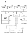
- FIG. 1 is a diagram showing an overall configuration of an extracorporeal circulation device according to an embodiment of the present invention.
- FIG. 2 is a diagram illustrating an example of a functional configuration of the controller of the extracorporeal circulation apparatus.
- FIG. 3 is a diagram illustrating an example of the output signal of the bubble sensor and the change over time of the evaluation parameter.
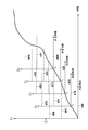
- FIG. 4 is a diagram for explaining the relationship between the time change of the evaluation parameter and the interlocking operation.
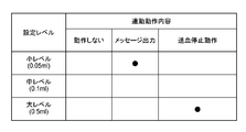
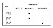
- FIG. 5 is a diagram illustrating an example of the setting contents of the interlocking operation.
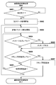
- FIG. 6 is a flowchart showing the flow of the linked operation control process in the controller.
- FIG. 7 is a diagram illustrating an example of setting contents of the interlocking operation.
- FIG. 8 is a diagram illustrating an example of setting contents of the interlocking operation.
- FIG. 1 is a diagram illustrating an example of the overall configuration of an extracorporeal circulation device 100 according to an embodiment of the present invention.
- the extracorporeal circulation device 100 is called PCPS (percutaneous cardiopulmonary support) and performs cardiopulmonary assist operations (extracorporeal circulation operation, priming operation).
- the extracorporeal circulation apparatus 100 has a blood extracorporeal circuit (hereinafter referred to as a circulation circuit) indicated by an arrow in the figure.
- a circulation circuit blood extracorporeal circuit
- the blood of the subject 130 is circulated extracorporeally using this circulation circuit.
- the priming operation refers to an operation of removing bubbles in the circuit by circulating the priming solution in the circulation circuit in a state where the circulation circuit is sufficiently filled with the priming solution (for example, physiological saline).
- the priming solution for example, physiological saline
- the extracorporeal circulation device 100 includes a controller 110 that functions as a control device, a drive motor 111, a centrifugal pump 112, an oxygenator 113, an oxygen supply source 117, a catheter (venous side) 119, and a catheter (arterial side) 120.
- the catheter (arterial side) 120 pumps blood toward the body of the subject 130, and the catheter (venous side) 119 performs blood removal from the body of the subject 130.
- the centrifugal pump 112 is also called a centrifugal artificial heart, drives a rotating body provided inside, applies pressure to the blood, and circulates the blood in the circulation circuit.
- the drive motor 111 gives a rotational driving force to the rotating body of the centrifugal pump 112.
- the artificial lung 113 performs blood circulation and blood gas exchange (oxygen addition, carbon dioxide removal, etc.).
- the oxygen supply source 117 is realized by, for example, an oxygen cylinder and supplies oxygen to be added to blood.
- the oxygen supplied from the oxygen supply source 117 is used at the time of gas exchange by the artificial lung 113.
- the bubble sensor 114 detects bubbles contained in the priming liquid or blood flowing in the circulation circuit during the priming operation and the extracorporeal circulation operation by a predetermined detection method (ultrasonic wave, light, etc.).
- the blood filter 116 filters blood or removes bubbles in the blood.
- the flow sensor 115 includes, for example, a built-in ultrasonic transceiver, and detects the flow rate of the priming liquid or blood in the circulation circuit.
- the clamp 122 is a member for closing the tube so as to forcibly stop the blood supply toward the body of the subject 130 during the extracorporeal circulation operation.
- the clamp 122 is set to a linked operation control mode that automatically performs a closing operation in conjunction with the clamp 122 when it is determined based on the output signal from the bubble sensor 114 that an abnormality that immediately stops blood feeding has occurred. It is possible to operate in case.
- the branch line 118 switches the flow path of the circulation circuit. Specifically, during an extracorporeal circulation operation in which the blood of the subject 130 is circulated extracorporeally, a circulation circuit passing through the body of the subject 130 is constructed as shown in 1A of FIG. Circulate blood. During the priming operation, as shown in 1B of FIG. 1, the circuit of the circulation circuit to the inside of the body of the subject 130 is blocked by the branch line 118 (in other words, the circulation circuit that passes only the outside of the subject 130 (in other words, the subject A circulation circuit that does not pass through the body of the person 130 is constructed, and the circulation circuit is filled with the priming liquid (without passing through the body of the subject) to circulate the priming liquid.
- one or a plurality of bubble discharge ports for discharging bubbles are provided on the circulation circuit.
- the bubbles in the circulation circuit are circulated. It will be discharged from the bubble discharge port.
- the controller 110 comprehensively controls the extracorporeal circulation operation and the priming operation in the extracorporeal circulation device 100.
- the centrifugal motor 112 is driven by controlling the drive motor 111.
- the bubble sensor 114 is controlled to acquire an output signal from the bubble sensor 114, or the flow rate sensor 115 is controlled to acquire a flow rate value.
- the clamp 122 is closed.
- the controller 110 controls the execution of the priming operation.
- a circulation circuit that does not pass through the body of the subject 130 is constructed by the branch line 118 as shown in 1B of FIG.
- the priming liquid supply source 121 is connected to the branch line 118, and the priming liquid is supplied from the priming liquid supply source 121 into the circulation circuit.
- the circulation circuit is filled with the priming liquid.
- the centrifugal pump 112 is driven by the control of the controller 110, and the priming liquid circulates in the circulation circuit a plurality of times. Bubbles in the circulation circuit are discharged from the bubble discharge port or the like with this circulation. Further, the bubble sensor 114 may detect the presence or absence of bubbles flowing in the circulation circuit during the priming operation.
- the user who confirms that the priming is completed switches the branch line 118 and constructs a circulation circuit that passes through the body of the subject 130 as shown in FIG. 1A. Thereby, the blood of the subject 130 is circulated extracorporeally.
- the extracorporeal circulation operation starts, blood that has been removed from the catheter (vein side) 119 enters the oxygenator 113 via the centrifugal pump 112.
- gas exchange that is, processing such as oxygen addition and carbon dioxide removal is performed.
- the filtered blood is sent from the catheter (arterial side) 120 into the body of the subject 130 through the blood filter 116 and the like.
- the blood flow of the subject 130 from the catheter (vein side) 119 to the catheter (arterial side) 120 is continuously performed.
- the bubble sensor 114 detects bubbles in the circulation circuit even during the extracorporeal circulation operation, and when it is necessary to stop the blood supply, the clamp 122 is closed. .
- the controller 110 has, as its functional configuration, a control unit (computer) 201, an operation unit 202, a display unit 203, a timer unit 204, a storage unit (computer-readable recording medium) 205, and an I / F unit 206. And a communication unit 207.
- the control unit 201 includes, for example, a CPU (Central Processing Unit), a ROM (Read Only Memory), a RAM (Random Access Memory), and the like, and various programs for realizing the above-described cardiopulmonary assist operation are stored in the ROM. (The description is omitted here).
- a CPU Central Processing Unit
- ROM Read Only Memory
- RAM Random Access Memory
- the operation unit 202 is realized by, for example, various buttons and inputs an instruction from a medical worker.
- the display unit 203 is realized by, for example, a display such as a monitor (including an output unit that outputs an alarm sound), and displays various types of information (including a message) to the user. Note that a part or all of the operation unit 202 and the display unit 203 may be realized as a touch panel with an audio speaker, for example.
- the timer unit 204 measures various times.
- the storage unit 205 is realized by, for example, a ROM and a RAM, and is executed by the control unit 201 in the interlocking operation control mode, and stops extracorporeal circulation based on an output signal from the bubble sensor 114 during the extracorporeal circulation operation.
- a program that functions as the interlocking operation control unit 210 is stored. Further, an output signal output from the bubble sensor 114 during the extracorporeal circulation operation is stored as the bubble data 211.
- the details of the interlocking operation control process realized by the control unit 201 executing a program that functions as the interlocking operation control unit 210 will be described later.
- the storage unit 205 may be mounted in the control unit 201.
- the I / F unit 206 exchanges various signals with an external device. Note that an output signal from the bubble sensor 114 or the like is taken into the controller 110 via the I / F unit 206. Further, the centrifugal pump 112, the clamp 122, and the like are controlled by the controller 110 via the I / F unit 206.
- the communication unit 207 communicates with the communication unit 220 attached to the medical staff.
- the communication between the communication unit 207 and the communication unit 220 may be short-range wireless communication such as Bluetooth (registered trademark) or wireless communication using a wireless LAN such as Wi-Fi.
- 3a in FIG. 3 schematically shows the time change of the output signal output from the bubble sensor 114 during the extracorporeal circulation operation.
- a signal such as an ultrasonic wave or light
- the signal strength of the received signal decreases when bubbles pass through the tube.
- the degree of decrease in the signal intensity is approximately proportional to the size of the bubble passing through the tube, and therefore corresponds to the volume of the bubble by calculating the area of the region where the signal intensity is lower than the predetermined threshold. Values (v 1 to v 12 ) can be calculated.
- the bubbles mixed in the circulation circuit during the extracorporeal circulation operation are divided and flow as many small bubble groups depending on the blood feeding speed (flow velocity). For this reason, the volume (v 1 to v 12 ) of each bubble is also a small value.
- the extracorporeal circulation device 100 a value obtained by accumulating the volume (v 1 to v 12 ) of each of the small divided bubbles is used as the evaluation parameter ⁇ v in the interlocking operation control process. .
- 3b of FIG. 3 schematically shows how the evaluation parameter ⁇ v in the interlocking operation control process changes within a predetermined time. As shown in 3b of FIG. 3, the evaluation parameter ⁇ v gradually increases with time.
- the clamp 122 is closed when the evaluation parameter ⁇ v reaches a predetermined level. Further, before the clamp 122 is closed, the message is output when the evaluation parameter ⁇ v reaches a predetermined level lower than the level at which the clamp 122 is closed.
- the medical staff can recognize the abnormality before the clamp 122 performs the closing operation, and can secure time for searching for the cause of the generation of bubbles.
- FIG. 4 is a diagram for explaining the algorithm of the interlocking operation control process.
- the horizontal axis indicates the elapsed time after the start of extracorporeal circulation operation
- the vertical axis indicates the evaluation parameter ⁇ v.
- the evaluation parameter ⁇ v increases with the passage of time. Therefore, in the extracorporeal circulation apparatus 100 according to the present embodiment, the evaluation parameter ⁇ v has reached a level at which a message should be output or has reached a level at which the clamp 122 is closed in a predetermined time (for example, 10 minutes). Monitor whether you did. Note that the starting point for counting a predetermined time to be monitored and the evaluation parameter ⁇ v are sequentially updated.
- the evaluation parameter ⁇ v indicates whether or not the evaluation parameter ⁇ v has reached the message output level 401 and the clamp occlusion operation level 402 during a predetermined time (for example, 10 minutes) after the start of the extracorporeal circulation operation. It shows how to monitor. However, when the message output level 401 and the clamp closing operation level 402 are reached after the elapse of a predetermined time (for example, 10 minutes), the message output and the clamp 122 are not blocked.
- a predetermined time for example, 10 minutes
- a predetermined time has elapsed time T 1 (e.g., 10 minutes) until elapses
- evaluation parameters ⁇ v is, messaging level 411 and the clamp It shows a state of monitoring whether or not the closing operation level 412 has been reached.
- T 1 e.g. 10 minutes
- the message output level 401 and the clamp closing operation level 402 are reached after a lapse of a predetermined time (for example, 10 minutes) after the time T 1 has elapsed, the message output becomes invalid and the clamp 122 is blocked. Do not do.
- the clamp 122 By controlling the interlocking operation by such an algorithm, when a large number of divided small bubbles flow within a predetermined time, the clamp 122 can be surely closed, and medical personnel can It is possible to notify that the possibility of the closing operation of the clamp 122 is increasing.
- FIG. 5 is a diagram showing an example of a setting screen for setting the message output level and the clamp closing operation level.
- 501 indicates the level of the evaluation parameter ⁇ v.
- the cumulative value 0.05 ml of the volume of bubbles flowing per predetermined time (for example, 10 minutes) is set as the small level. Yes.
- a cumulative value of 0.1 ml of the volume of bubbles flowing per predetermined time (for example, 10 minutes) is set.
- a cumulative value of 0.5 ml of the volume of bubbles flowing per predetermined time (for example, 10 minutes) is set.
- Reference numeral 502 denotes an area where “does not operate” is set as the contents of the interlocking operation.
- the evaluation parameter ⁇ v is set to a low level (the cumulative value of the volume of bubbles flowing per predetermined time is 0.05 ml). ) Is set so that no operation is performed even if it has reached.
- Reference numeral 503 denotes an area in which “message output” is set as the contents of the interlocking operation.
- the evaluation parameter ⁇ v is an intermediate level (the cumulative value of the volume of bubbles flowing per predetermined time is 0. 1 ml), a message is output.
- Reference numeral 504 denotes an area in which “blood sending stop operation” is set as the contents of the interlocking operation.
- the evaluation parameter ⁇ v is set to a large level (the cumulative value of the volume of bubbles flowing per predetermined time is When reaching 0.5 ml), the clamp 122 is closed to stop blood feeding.
- FIG. 6 is a flowchart showing the flow of the interlocking operation control process in the extracorporeal circulation device 100.
- step S601 when the interlocking operation control process is activated, it is determined in step S601 whether a message output level or a clamp closing operation level is set. If it is determined in step S601 that the message output level or the clamp closing operation level is not set, the medical staff waits until it is set.
- step S601 If it is determined in step S601 that it has been set, the process proceeds to step S602 to start acquisition of bubble data, and in step S603, calculation of the evaluation parameter ⁇ v is started.
- step S604 it is determined whether or not the evaluation parameter ⁇ v has reached the message output level. If it is determined in step S604 that the message output level has been reached, the process proceeds to step S605, where a message indicating that the accumulated value of the volume of bubbles has increased and the clamp 122 may be closed is output. Then, the process proceeds to step S606.
- step S604 determines whether the message output level has been reached (or if the message output level is not set). If it is determined in step S604 that the message output level has not been reached (or if the message output level is not set), the process proceeds directly to step S606.
- step S606 it is determined whether or not the evaluation parameter ⁇ v has reached the clamp closing operation level. If it is determined in step S606 that the clamp closing operation level has not been reached, the process advances to step S608 to determine whether or not a predetermined time has elapsed.
- step S608 If it is determined in step S608 that the predetermined time has not elapsed, the process returns to step S604, and whether the evaluation parameter ⁇ v has reached the message output level or has reached the clamp closing operation level. Monitor whether or not.
- step S608 if it is determined in step S608 that the predetermined time has elapsed, the process returns to step S603, the start point for counting the predetermined time is shifted, and the evaluation parameter ⁇ v is calculated. Specifically, among the plurality of values v constituting the evaluation parameter ⁇ v, the old value v is subtracted and the newly calculated value v is added.
- step S606 determines whether the evaluation parameter ⁇ v has reached the clamp closing operation level. If it is determined in step S606 that the evaluation parameter ⁇ v has reached the clamp closing operation level, the process proceeds to step S607, and after closing the clamp 122, the interlocking operation control process is terminated.
- the extracorporeal circulation device 100 calculates a cumulative value of the volume of bubbles as an evaluation parameter based on the output signal of the bubble sensor, and based on the evaluation parameter ⁇ v.
- the clamp is closed.
- the extracorporeal circulation device 100 has a configuration in which a message output level can be set in addition to the clamp blockage level. This makes it possible to notify the medical staff that there is a possibility that the clamp closing operation may be performed before the evaluation parameter ⁇ v reaches the clamp closing operation level. As a result, since the medical staff can recognize the abnormality before the clamp closing operation is executed, it is possible to shorten the blood sending stop time associated with the clamp closing operation.
- the message output is set to the medium level
- the blood sending stop operation is set to the large level. It is not limited to this.
- a message output may be set to a small level and a blood sending stop operation may be set to a large level.
- the message output is 1 to It may be configured to be automatically set to one of the (m ⁇ 1) th levels. Or it is good also as a structure which prohibits setting a message output from the mth to the nth.
- the blood sending stop operation is automatically set to any one of the (m + 1) th to nth levels. It may be configured. Or it is good also as a structure which prohibits setting a blood-feed stop operation
- the selection range of the other level is maintained so that the relationship between the message output level and the clamp closing operation level is maintained. May be configured to be defined.
- FIG. 8 shows that when three levels (small level, medium level, large level) are set as the level 501 of the evaluation parameter ⁇ v, a plurality of message output levels (small level and medium level) are set. Is shown.
- the first message is output when the evaluation parameter ⁇ v reaches a small level, and when the evaluation parameter ⁇ v reaches a medium level, the first message is different from the first message. 2 messages can be output.
- the second message is a message indicating that the clamp 122 is approaching the closing operation, and is output in a different notification mode (color, character size, etc.) from the first message. Shall.
- the level 501 of the evaluation parameter ⁇ v is individually set on the setting screen for setting the message output level and the clamp closing operation level.
- the present invention is not limited to this. For example, when a large level is set, a value obtained by multiplying the large level by a predetermined coefficient (a value smaller than 1) is automatically set as a medium level or a small level. Also good.
- a value obtained by multiplying the small level by a predetermined coefficient (a value greater than 1) is automatically set as a medium level or a large level. May be.
- the present invention is not limited to this, and for example, the rotational speed of the drive motor 111 of the centrifugal pump 112 It may be a lowering operation.
Landscapes
- Health & Medical Sciences (AREA)
- Heart & Thoracic Surgery (AREA)
- Vascular Medicine (AREA)
- Biomedical Technology (AREA)
- Engineering & Computer Science (AREA)
- Anesthesiology (AREA)
- Cardiology (AREA)
- Hematology (AREA)
- Life Sciences & Earth Sciences (AREA)
- Animal Behavior & Ethology (AREA)
- General Health & Medical Sciences (AREA)
- Public Health (AREA)
- Veterinary Medicine (AREA)
- External Artificial Organs (AREA)
- Infusion, Injection, And Reservoir Apparatuses (AREA)
Abstract
気泡の態様によらず、被検者への悪影響を確実に回避でき、かつ、送血停止時間を短縮することが可能な体外循環装置を提供することを目的とする。本発明は、体外循環装置であって、気泡センサと、前記気泡センサより出力された信号に基づいて、混入した各気泡の体積の累積値に対応する評価パラメータを算出する手段と、所定時間の間に、前記算出される前記評価パラメータの値が、第1のレベルに到達した場合に、メッセージを出力する手段と、前記所定時間の間に、前記算出される前記評価パラメータの値が、前記第1のレベルよりも高い第2のレベルに到達した場合に、クランプを閉塞動作させる手段とを備えることを特徴とする。
Description
本発明は、循環装置における制御技術に関するものである。
一般に、体外循環や補助循環等を行う循環装置では、所定の大きさの気泡が検出された場合に、連動してクランプを閉塞動作させ、被検者への送血を停止させる連動動作制御機能が組み込まれている。当該連動動作制御機能を用いれば、被検者の生死に関わるような気泡が検出された場合に、ただちに送血を停止させることができ、被検者に及ぼす悪影響を確実に回避することができる。また、送血を停止させている間に気泡の発生原因を取り除き、ただちに送血を再開させることができれば、被検者の死亡リスクを低減させることもできる。
しかしながら、循環装置の場合、送血速度(流速)によっては、混入した気泡が、循環回路内を大きなかたまりとして流れるのではなく、分裂して、多数の小さな気泡群として流れていく。このため、それぞれの気泡の大きさは、ただちにクランプを閉塞動作させるレベルにはないが、一定時間連続した場合には、気泡の総量が、被検者に悪影響を及ぼすレベルに至るといった事態が生じえる。このようなことから、連動動作制御機能を構築するにあたっては、多数の小さな気泡群が流れるケースを考慮しておくことが望ましい。
また、従来の循環装置では、クランプを閉塞動作させてから、医療従事者等が気泡の発生原因を探し出し、取り除くといった作業フローになっていたため、送血停止時間が長くなってしまうといった問題もあった。このようなことから、連動動作制御機能を構築するにあたっては、更に、クランプを閉塞動作させる前に、気泡の発生原因を探し出すことができるような構成になっていることが望ましい。
本発明は上記課題に鑑みてなされたものであり、気泡の態様によらず、被検者への悪影響を確実に回避でき、かつ、送血停止時間を短縮することが可能な循環装置を提供することを目的とする。
上記の目的を達成するために、本発明に係る循環装置は以下のような構成を備える。即ち、
被検者の血液を循環回路を用いて体外で循環させる循環装置であって、
前記循環回路に配され、循環される血液に混入する各気泡の大きさに応じた信号を出力する検出手段と、
前記検出手段より出力された信号に基づいて、混入した各気泡の体積の累積値に対応する評価パラメータを算出する算出手段と、
所定時間の間に、前記算出手段により算出される前記評価パラメータの値が、第1のレベルに到達した場合に、報知する報知手段と、
前記所定時間の間に、前記算出手段により算出される前記評価パラメータの値が、前記第1のレベルよりも高い第2のレベルに到達した場合に、前記循環回路における血液の循環を停止する停止手段とを備えることを特徴とする。
被検者の血液を循環回路を用いて体外で循環させる循環装置であって、
前記循環回路に配され、循環される血液に混入する各気泡の大きさに応じた信号を出力する検出手段と、
前記検出手段より出力された信号に基づいて、混入した各気泡の体積の累積値に対応する評価パラメータを算出する算出手段と、
所定時間の間に、前記算出手段により算出される前記評価パラメータの値が、第1のレベルに到達した場合に、報知する報知手段と、
前記所定時間の間に、前記算出手段により算出される前記評価パラメータの値が、前記第1のレベルよりも高い第2のレベルに到達した場合に、前記循環回路における血液の循環を停止する停止手段とを備えることを特徴とする。
本発明によれば、気泡の態様によらず、被検者への悪影響を確実に回避でき、かつ、送血停止時間を短縮することが可能な循環装置を提供できるようになる。
本発明のその他の特徴及び利点は、添付図面を参照とした以下の説明により明らかになるであろう。なお、添付図面においては、同じ若しくは同様の構成には、同じ参照番号を付す。
添付図面は明細書に含まれ、その一部を構成し、本発明の実施の形態を示し、その記述と共に本発明の原理を説明するために用いられる。
図1は、本発明の一実施形態に係る体外循環装置の全体構成を示す図である。
図2は、体外循環装置のコントローラの機能構成の一例を示す図である。
図3は、気泡センサの出力信号の一例及び評価パラメータの時間変化を示す図である。
図4は、評価パラメータの時間変化と、連動動作との関係を説明するための図である。
図5は、連動動作の設定内容の一例を示す図である。
図6は、コントローラにおける連動動作制御処理の流れを示すフローチャートである。
図7は、連動動作の設定内容の一例を示す図である。
図8は、連動動作の設定内容の一例を示す図である。
以下、本発明の各実施形態について添付図面を参照しながら詳細に説明する。なお、以下に述べる実施の形態は、本発明の好適な具体例であるから、技術的に好ましい種々の限定が付されているが、本発明の範囲は、以下の説明において特に本発明を限定する旨の記載がない限り、これらの態様に限られるものではない。
[第1の実施形態]
<1.体外循環装置の全体構成>
はじめに本発明の一実施形態に係る体外循環装置の全体構成について説明する。図1の1Aは、本発明の一実施形態に係る体外循環装置100の全体構成の一例を示す図である。
<1.体外循環装置の全体構成>
はじめに本発明の一実施形態に係る体外循環装置の全体構成について説明する。図1の1Aは、本発明の一実施形態に係る体外循環装置100の全体構成の一例を示す図である。
体外循環装置100は、PCPS(percutaneous cardiopulmonary support)などと呼ばれ、心肺補助動作(体外循環動作、プライミング動作)を行う。体外循環装置100は、図中矢印で示す血液体外循環回路(以下、循環回路と呼ぶ)を有している。体外循環装置100では、プライミング動作を行った後、この循環回路を用いて被検者130の血液を体外循環させる。
なお、プライミング動作とは、プライミング液(例えば、生理食塩水)で循環回路を十分に満たした状態で、循環回路内でプライミング液を循環させ、当該回路内の気泡を除去する動作をいう。
体外循環装置100は、制御装置として機能するコントローラ110と、ドライブモータ111と、遠心ポンプ112と、人工肺113と、酸素供給源117と、カテーテル(静脈側)119と、カテーテル(動脈側)120と、気泡センサ114と、流量センサ115と、血液フィルタ116と、分岐ライン118と、クランプ122とを備える。なお、これら各構成の間は、柔軟性を有するチューブ等によって接続されており、当該チューブの内腔が血液またはプライミング液の流路を構成している。
カテーテル(動脈側)120は、被検者130の体内に向けて送血し、カテーテル(静脈側)119は、被検者130の体内から脱血を行う。
遠心ポンプ112は、遠心式人工心臓とも呼ばれ、内部に設けられた回転体を駆動させて血液に圧力を与え、循環回路内で血液を循環させる。ドライブモータ111は、遠心ポンプ112の回転体に回転駆動力を与える。
人工肺113は、血液の循環と血液のガス交換(酸素付加、二酸化炭素除去等)とを行う。酸素供給源117は、例えば、酸素ボンベ等で実現され、血液に付加する酸素を供給する。酸素供給源117から供給される酸素は、人工肺113によるガス交換時に使用される。
気泡センサ114は、プライミング動作時及び体外循環動作時に循環回路内を流れるプライミング液あるいは血液に含まれる気泡を所定の検出方法(超音波、光等)により検出する。血液フィルタ116は、血液をろ過したり、血液中の気泡を除去したりする。流量センサ115は、例えば、超音波の送受信器を内蔵して構成され、循環回路内のプライミング液あるいは血液の流量を検出する。
クランプ122は、体外循環動作時に、被検者130の体内に向けての送血を強制的に停止させるべく、チューブを閉塞させるための部材である。クランプ122は、気泡センサ114からの出力信号に基づいて、送血をただちに停止させる異常が発生したと判定した場合に、連動して自動的に閉塞動作を行う連動動作制御モードが設定されている場合に動作させることが可能である。
分岐ライン118は、循環回路の流路を切り替える。具体的には、被検者130の血液を体外循環させる体外循環動作時には、図1の1Aに示すように、被検者130の体内を通る循環回路を構築し、被検者130の体外で血液を循環させる。プライミング動作時には、図1の1Bに示すように、分岐ライン118によって被検者130の体内への循環回路の経路を遮断して被検者130の体外のみを通る循環回路(言い換えれば、被検者130の体内を通らない循環回路)を構築し、プライミング液で循環回路内を満たして(被検者の体内を通らずに)プライミング液を循環させる。循環回路上には、気泡を排出するための1又は複数の気泡排出ポート(不図示)が設けられており、循環回路内でプライミング液を複数周循環させることにより、循環回路内の気泡が当該気泡排出ポートから排出されることとなる。
コントローラ110は、体外循環装置100における体外循環動作及びプライミング動作を統括制御する。コントローラ110においては、例えば、ドライブモータ111を制御して遠心ポンプ112を駆動させる。また、気泡センサ114を制御して気泡センサ114からの出力信号を取得したり、流量センサ115を制御して流量値を取得したりする。更に、連動動作制御モードにあっては、気泡センサ114からの出力信号に基づいて、送血を停止させる必要がある異常を検出した場合には、クランプ122を閉塞動作させる。
次に、図1の1A及び1Bに示す体外循環装置100を用いて心肺補助動作(体外循環動作、プライミング動作)を行う際の処理の流れについて簡単に説明する。
心肺補助動作が開始されると、コントローラ110は、プライミング動作の実行を制御する。プライミング動作時には、図1の1Bに示すように、分岐ライン118によって被検者130の体内を通らない循環回路が構築される。また、このとき、プライミング液供給源121が分岐ライン118に接続され、当該プライミング液供給源121から循環回路内にプライミング液が供給される。これにより、循環回路内は、プライミング液で満たされることになる。
そして、コントローラ110の制御によって遠心ポンプ112が駆動し、プライミング液が循環回路内を複数周循環する。循環回路内の気泡は、この循環とともに気泡排出ポート等から排出される。また、プライミング動作時に気泡センサ114によって当該循環回路内を流れる気泡の有無を検出してもよい。
プライミングが完了したことを確認したユーザは、分岐ライン118を切り替え、図1の1Aに示すように、被検者130の体内を通る循環回路を構築する。これにより、被検者130の血液が体外循環される。
体外循環動作が始まると、カテーテル(静脈側)119から脱血されてくる血液が、遠心ポンプ112を経て人工肺113に入る。人工肺113では、上述した通り、ガス交換、すなわち、酸素付加や二酸化炭素除去等の処理が行われる。その後、血液フィルタ116等を経て、ろ過された血液が、カテーテル(動脈側)120から被検者130の体内に送血される。このカテーテル(静脈側)119~カテーテル(動脈側)120までの被検者130の血液の流れが連続的に行われる。なお、連動動作制御モードにあっては、体外循環動作時にも気泡センサ114によって循環回路内の気泡の検出が行われ、送血を停止させる必要がある場合には、クランプ122の閉塞動作を行う。
以上が、本実施形態に係る体外循環装置100の全体構成及び心肺補助動作の流れの一例についての説明である。なお、図1の1A及び1Bに示す体外循環装置100の構成は、あくまでも一例にすぎず、その構成は適宜変更されてもよい。
<2.コントローラの機能構成>
次に、図2を用いて、図1に示すコントローラ110の機能構成の一例について説明する。
次に、図2を用いて、図1に示すコントローラ110の機能構成の一例について説明する。
コントローラ110は、その機能構成として、制御部(コンピュータ)201と、操作部202と、表示部203と、タイマ部204と、記憶部(コンピュータ読取可能な記録媒体)205と、I/F部206と、通信部207とを備える。
制御部201は、例えば、CPU(Central Processing Unit)、ROM(Read Only Memory)及びRAM(Random Access Memory)等で構成され、ROMには、上述した心肺補助動作を実現するための各種プログラムが格納されているものとする(なお、ここでは説明を省略する)。
操作部202は、例えば、各種ボタン等で実現され、医療従事者からの指示を入力する。表示部203は、例えば、モニタ等の表示器(警報を音声出力する出力部を含む)で実現され、各種情報(メッセージを含む)をユーザに向けて表示する。なお、操作部202及び表示部203の一部又は全部は、例えば、音声スピーカ付のタッチパネルとして実現されてもよい。
タイマ部204は、各種時間の計時を行う。記憶部205は、例えば、ROM及びRAM等で実現されており、連動動作制御モードにおいて、制御部201において実行され、体外循環動作中の気泡センサ114からの出力信号に基づいて、体外循環を停止させる連動動作制御部210として機能するプログラムを格納している。また、体外循環動作中に気泡センサ114から出力された出力信号を、気泡データ211として格納している。なお、連動動作制御部210として機能するプログラムが制御部201により実行されることにより実現される連動動作制御処理の詳細は後述する。また、記憶部205は制御部201の中に搭載されていてもよい。
I/F部206は、外部装置との間で各種信号の授受を行う。なお、気泡センサ114等からの出力信号は、I/F部206を介してコントローラ110に取り込まれる。また、遠心ポンプ112やクランプ122等は、I/F部206を介してコントローラ110により制御される。
通信部207は、医療従事者に装着された通信部220との間で通信を行う。なお、通信部207と通信部220との間の通信は、Bluetooth(登録商標)等の近距離無線通信であっても、Wi-Fi等の無線LANによる無線通信であってもよい。
以上が、コントローラ110についての機能構成の一例についての説明である。なお、図2に示す機能構成はあくまでも一例であり、新たな構成が追加されてもよいし、また、不要な構成が適宜省略されても良い。
<3.気泡センサからの出力信号の説明と連動動作制御処理の概要>
次に、気泡センサ114からの出力信号と、当該出力信号に基づいて実行される連動動作制御処理の概要について説明する。
次に、気泡センサ114からの出力信号と、当該出力信号に基づいて実行される連動動作制御処理の概要について説明する。
図3の3aは、体外循環動作中に気泡センサ114から出力される出力信号の時間変化を模式的に示したものである。図3の3aに示すように、超音波や光等の信号を循環回路を形成するチューブに対して送信した場合、受信信号は、チューブ内を気泡が通過した場合に、信号強度が低下する。
ここで、信号強度の低下度合いは、チューブ内を通過する気泡の大きさに概ね比例することから、信号強度が所定の閾値よりも低い領域の面積を算出することにより、気泡の体積に対応する値(v1~v12)を算出することができる。
上述したように、体外循環動作時に循環回路に混入する気泡は、送血速度(流速)によっては、分裂して多数の小さな気泡群として流れていく。このため、それぞれの気泡の体積(v1~v12)も小さな値となる。
しかし、このような体積の小さな気泡であっても、多数が気泡群として連続して流れた場合、体積の累積値は大きなものとなり、被検者に対して悪影響を及ぼすことが考えられる。そこで、本実施形態に係る体外循環装置100では、小さく分裂された気泡それぞれの体積(v1~v12)を累積して得られる値を、連動動作制御処理における評価パラメータΣvとして用いることとした。
図3の3bは、連動動作制御処理における評価パラメータΣvの所定時間内における変化の様子を模式的に示したものである。図3の3bに示すように、時間経過とともに、評価パラメータΣvは、徐々に大きくなっていく。
ここで、本実施形態に係る体外循環装置100では、評価パラメータΣvが所定のレベルに到達した場合に、クランプ122を閉塞動作させる。更に、クランプ122を閉塞動作させる前であって、評価パラメータΣvが、クランプ122を閉塞動作させるレベルよりも低い所定のレベルに到達した場合に、メッセージを出力する。
このように、評価パラメータΣvが、所定のレベルに到達した場合に、直ちに、クランプ122を閉塞動作させるのではなく、クランプ122の閉塞動作させるレベルに近づいていることを、予め、メッセージとして出力する構成とすることで、医療従事者は、クランプ122が閉塞動作するよりも前に、異常を認識することが可能となり、気泡の発生原因を探し出す時間を確保することが可能となる。
つまり、従来のように、クランプの閉塞動作が実行されてから、気泡の発生原因を探し出す場合と比較して、クランプ閉塞動作に伴う送血停止時間を短縮させることが可能となる。
<4.連動動作制御処理のアルゴリズムの説明>
次に、上記連動動作制御処理のアルゴリズムについて簡単に説明する。図4は、連動動作制御処理のアルゴリズムを説明するための図である。図4において、横軸は、体外循環動作開始後の経過時間を示しており、縦軸は、評価パラメータΣvを示している。
次に、上記連動動作制御処理のアルゴリズムについて簡単に説明する。図4は、連動動作制御処理のアルゴリズムを説明するための図である。図4において、横軸は、体外循環動作開始後の経過時間を示しており、縦軸は、評価パラメータΣvを示している。
図4に示すように、体外循環動作開始後、評価パラメータΣvは、時間の経過とともに増加していく。そこで、本実施形態に係る体外循環装置100では、所定時間(例えば、10分間)内に、評価パラメータΣvが、メッセージ出力すべきレベルに到達したか、あるいは、クランプ122を閉塞動作させるレベルに到達したかを監視する。なお、監視対象となる所定時間をカウントする開始点及び評価パラメータΣvは、逐次更新されていくものとする。
図4の400は、体外循環動作開始後から所定時間(例えば、10分)が経過するまでの間に、評価パラメータΣvが、メッセージ出力レベル401及びクランプ閉塞動作レベル402に到達したか否かを監視する様子を示したものである。ただし、所定時間(例えば、10分)経過以降にメッセージ出力レベル401及びクランプ閉塞動作レベル402に到達した場合には無効となり、メッセージ出力及びクランプ122の閉塞は行わない。
同様に、図4の410は、体外循環動作開始後、時間T1が経過してから所定時間(例えば、10分)が経過するまでの間に、評価パラメータΣvが、メッセージ出力レベル411及びクランプ閉塞動作レベル412に到達したか否かを監視する様子を示したものである。また、同様に、時間T1が経過してから所定時間(例えば、10分)経過以降にメッセージ出力レベル401及びクランプ閉塞動作レベル402に到達した場合には無効となり、メッセージ出力及びクランプ122の閉塞は行わない。
以下、同様に、図4の420、430、440は、それぞれ、体外循環動作開始後、時間T2、T3、T4が経過してから、所定時間(例えば、10分)が経過するまでの間に、評価パラメータΣvが、メッセージ出力レベル421、431、441及びクランプ閉塞動作レベル422、432、442に到達したか否かを監視する様子を示したものである。また、同様に、時間T2、T3、T4が経過してから所定時間(例えば、10分)経過以降にメッセージ出力レベル401及びクランプ閉塞動作レベル402に到達した場合には無効となり、メッセージ出力及びクランプ122の閉塞は行わない。
このようアルゴリズムにより、連動動作を制御することにより、分裂した小さな気泡群が所定時間内に多数流れた場合に、確実に、クランプ122を閉塞動作させることができるとともに、医療従事者に事前に、クランプ122の閉塞動作の可能性が高まっていることを報知することが可能となる。
<5.連動動作設定内容>
次に、医療従事者が操作部202を介して、メッセージ出力レベル及びクランプ閉塞動作レベルを設定するための設定画面について説明する。
次に、医療従事者が操作部202を介して、メッセージ出力レベル及びクランプ閉塞動作レベルを設定するための設定画面について説明する。
図5は、メッセージ出力レベル及びクランプ閉塞動作レベルを設定するための設定画面の一例を示す図である。
図5において、501は評価パラメータΣvのレベルを示しており、図5の例では、小レベルとして、所定時間(例えば、10分)あたりに流れる気泡の体積の累積値0.05mlが設定されている。また、中レベルとして、所定時間(例えば、10分)あたりに流れる気泡の体積の累積値0.1mlが設定されている。更に、大レベルとして、所定時間(例えば、10分)あたりに流れる気泡の体積の累積値0.5mlが設定されている。
502は、連動動作の内容として、“動作しない”ことを設定する領域であり、図5の例では、評価パラメータΣvが、小レベル(所定時間あたりに流れる気泡の体積の累積値が0.05ml)に到達した場合であっても、何も動作しない設定となっている。
503は、連動動作の内容として、“メッセージ出力”することを設定する領域であり、図5の例では、評価パラメータΣvが、中レベル(所定時間あたりに流れる気泡の体積の累積値が0.1ml)に到達した場合に、メッセージ出力を行う設定となっている。
504は、連動動作の内容として、“送血停止動作”することを設定する領域であり、図5の例では、評価パラメータΣvが、大レベル(所定時間あたりに流れる気泡の体積の累積値が0.5ml)に到達した場合に、クランプ122を閉塞動作させ、送血を停止させる設定となっている。
<6.連動動作制御処理の流れ>
次に、本実施形態に係る体外循環装置100における連動動作制御処理の流れについて説明する。図6は、体外循環装置100における連動動作制御処理の流れを示すフローチャートである。
次に、本実施形態に係る体外循環装置100における連動動作制御処理の流れについて説明する。図6は、体外循環装置100における連動動作制御処理の流れを示すフローチャートである。
図6に示すように、連動動作制御処理が起動されると、ステップS601では、メッセージ出力レベルまたはクランプ閉塞動作レベルが設定されているか否かを判定する。ステップS601において、メッセージ出力レベルまたはクランプ閉塞動作レベルが設定されていないを判定された場合には、医療従事者により、設定されるまで待機する。
ステップS601において、設定されたと判定された場合には、ステップS602に進み、気泡データの取得を開始し、ステップS603では、評価パラメータΣvの算出を開始する。
ステップS604では、評価パラメータΣvが、メッセージ出力レベルに到達したか否かを判定する。ステップS604において、メッセージ出力レベルに到達したと判定された場合には、ステップS605に進み、気泡の体積の累積値が増加しており、クランプ122を閉塞動作させる可能性がある旨のメッセージを出力し、ステップS606に進む。
一方、ステップS604において、メッセージ出力レベルに到達していないと判定された場合(あるいは、メッセージ出力レベルが設定されていない場合も含む)には、直接、ステップS606に進む。
ステップS606では、評価パラメータΣvが、クランプ閉塞動作レベルに到達したか否かを判定する。ステップS606において、クランプ閉塞動作レベルに到達していないと判定された場合に、ステップS608に進み、所定時間が経過したか否かを判定する。
ステップS608において、所定時間が経過していないと判定された場合には、ステップS604に戻り、引き続き、評価パラメータΣvが、メッセージ出力レベルに到達したか否か、あるいはクランプ閉塞動作レベルに到達したか否かを監視する。
一方、ステップS608において、所定時間が経過したと判定された場合には、ステップS603に戻り、所定時間をカウントする開始点をずらした上で、評価パラメータΣvの算出を行う。具体的には、評価パラメータΣvを構成する複数の値vのうち、古い値vを減算して、新たに算出された値vを加算する。
一方、ステップS606において、評価パラメータΣvが、クランプ閉塞動作レベルに到達したと判定された場合には、ステップS607に進み、クランプ122を閉塞動作させた後に、連動動作制御処理を終了する。
以上の説明から明らかなように、本実施形態に係る体外循環装置100では、気泡センサの出力信号に基づいて、評価パラメータとして、気泡の体積の累積値を算出し、当該評価パラメータΣvに基づいて、クランプを閉塞動作させる構成とした。これにより、気泡が分裂して多数の小さな気泡群として流れた場合であっても(つまり、気泡の態様によらず)、被検者に対して気泡が悪影響を及ぼす事態を確実に回避することが可能となった。
また、本実施形態に係る体外循環装置100では、クランプ閉塞レベルに加えて、メッセージ出力レベルを設定できる構成とした。これにより、評価パラメータΣvがクランプ閉塞動作レベルに到達するよりも前に、医療従事者に対して、クランプの閉塞動作が行われる可能性がある旨を報知することが可能となった。この結果、医療従事者は、クランプ閉塞動作が実行されるよりも前に、異常を認識することが可能となるため、クランプ閉塞動作に伴う送血停止時間を短縮させることが可能となった。
[第2の実施形態]
上記第1の実施形態では、メッセージ出力レベル及びクランプ閉塞動作レベルを設定する設定画面において、中レベルにメッセージ出力を設定し、大レベルに送血停止動作を設定することとしたが、本発明はこれに限定されない。
上記第1の実施形態では、メッセージ出力レベル及びクランプ閉塞動作レベルを設定する設定画面において、中レベルにメッセージ出力を設定し、大レベルに送血停止動作を設定することとしたが、本発明はこれに限定されない。
例えば、図7に示すように、小レベルにメッセージ出力を設定し、大レベルに送血停止動作を設定するように構成してもよい。
また、例えば、評価パラメータΣvのレベル501として、n個のレベルが設定されており、送血停止動作を、m番目のレベルに選択的に設定した場合にあっては、メッセージ出力は、1~(m-1)番目のレベルのいずれかに自動的に設定されるように構成してもよい。あるいは、メッセージ出力を、m番目からn番目までに設定することを禁止する構成としてもよい。
同様に、メッセージ出力を、m番目のレベルに選択的に設定した場合にあっては、送血停止動作を、(m+1)番目からn番目のレベルのいずれかに自動的に設定されるように構成してもよい。あるいは、送血停止動作を、1番目からm番目までに設定することを禁止する構成としてもよい。
つまり、メッセージ出力レベルまたはクランプ閉塞動作レベルのいずれか一方のレベルが選択的に設定された場合、メッセージ出力レベルとクランプ閉塞動作レベルの高低の関係が維持されるように、他方のレベルの選択範囲が規定されるように構成してもよい。
[第3の実施形態]
上記第1及び第2の実施形態では、メッセージ出力レベル及びクランプ閉塞動作レベルを設定する設定画面において、メッセージ出力レベルを1つのみ設定する場合について説明したが、本発明はこれに限定されない。評価パラメータΣvのレベル501として複数のレベルが設定されている場合にあっては、メッセージ出力レベルを複数設定できるように構成してもよい。
上記第1及び第2の実施形態では、メッセージ出力レベル及びクランプ閉塞動作レベルを設定する設定画面において、メッセージ出力レベルを1つのみ設定する場合について説明したが、本発明はこれに限定されない。評価パラメータΣvのレベル501として複数のレベルが設定されている場合にあっては、メッセージ出力レベルを複数設定できるように構成してもよい。
図8は、評価パラメータΣvのレベル501として、3つのレベル(小レベル、中レベル、大レベル)が設定されている場合において、メッセージ出力レベルを、複数(小レベルと中レベル)に設定した様子を示している。
このように、メッセージ出力レベルを複数設定することで、評価パラメータΣvが小レベルに到達した際に、第1のメッセージを出力し、中レベルに到達した際に、第1のメッセージとは異なる第2のメッセージを出力することが可能となる。
なお、第2のメッセージは、クランプ122の閉塞動作の実行に、より近づいていることを示すメッセージであり、第1のメッセージとは異なる報知態様(色、文字の大きさ等)により出力されるものとする。
[第4の実施形態]
上記第1乃至第3の実施形態では、メッセージ出力レベル及びクランプ閉塞動作レベルを設定する設定画面において、評価パラメータΣvのレベル501を個別に設定する構成としたが、本発明はこれに限定されない。例えば、大レベルを設定した場合には、当該大レベルに所定の係数(1より小さい値)を乗算して得られた値を、中レベルまたは小レベルとして自動的に設定するように構成してもよい。
上記第1乃至第3の実施形態では、メッセージ出力レベル及びクランプ閉塞動作レベルを設定する設定画面において、評価パラメータΣvのレベル501を個別に設定する構成としたが、本発明はこれに限定されない。例えば、大レベルを設定した場合には、当該大レベルに所定の係数(1より小さい値)を乗算して得られた値を、中レベルまたは小レベルとして自動的に設定するように構成してもよい。
あるいは、小レベルを設定した場合には、当該小レベルに所定の係数(1よりも大きい値)を乗算して得られた値を、中レベルまたは大レベルとして自動的に設定するように構成してもよい。
[第5の実施形態]
上記第1乃至第4の実施形態では、送血停止動作としてクランプ122の閉塞動作を前提に説明したが、本発明はこれに限定されず、例えば、遠心ポンプ112のドライブモータ111の回転数を下げる動作であってもよい。
上記第1乃至第4の実施形態では、送血停止動作としてクランプ122の閉塞動作を前提に説明したが、本発明はこれに限定されず、例えば、遠心ポンプ112のドライブモータ111の回転数を下げる動作であってもよい。
[その他の実施形態]
本発明は上記実施の形態に制限されるものではなく、本発明の精神及び範囲から離脱することなく、様々な変更及び変形が可能である。従って、本発明の範囲を公にするために、以下の請求項を添付する。
本発明は上記実施の形態に制限されるものではなく、本発明の精神及び範囲から離脱することなく、様々な変更及び変形が可能である。従って、本発明の範囲を公にするために、以下の請求項を添付する。
Claims (10)
- 被検者の血液を循環回路を用いて体外で循環させる循環装置であって、
前記循環回路に配され、循環される血液に混入する各気泡の大きさに応じた信号を出力する検出手段と、
前記検出手段より出力された信号に基づいて、混入した各気泡の体積の累積値に対応する評価パラメータを算出する算出手段と、
所定時間の間に、前記算出手段により算出される前記評価パラメータの値が、第1のレベルに到達した場合に、報知する報知手段と、
前記所定時間の間に、前記算出手段により算出される前記評価パラメータの値が、前記第1のレベルよりも高い第2のレベルに到達した場合に、前記循環回路における血液の循環を停止する停止手段と
を備えることを特徴とする循環装置。 - 前記算出手段は、前記所定時間の開始点を逐次ずらしながら、前記所定時間の間の前記評価パラメータを算出することを特徴とする請求項1に記載の循環装置。
- 前記第1のレベル及び前記第2のレベルを設定する設定手段を更に備え、
前記設定手段は、
互いに異なる複数のレベルから、前記第1のレベル及び前記第2のレベルを選択的に設定するよう構成されており、
前記第1のレベルまたは前記第2のレベルのいずれか一方のレベルが選択された場合、前記第1のレベルと前記第2のレベルの高低の関係が維持されるように、他方のレベルの選択範囲が規定されることを特徴とする請求項2に記載の循環装置。 - 前記設定手段は、前記第1のレベルを複数設定できるように構成されており、
前記報知手段は、前記第1のレベルが複数設定されている場合、前記評価パラメータの値が、該複数の第1のレベルそれぞれに到達した場合に、互いに異なる報知態様により報知を行うことを特徴とする請求項3に記載の循環装置。 - 前記設定手段は、前記複数のレベルは、いずれか1つのレベルを設定した場合に、該設定したレベルに所定の係数を乗算することにより設定されることを特徴とする請求項3または4に記載の循環装置。
- 前記停止手段は、前記循環回路に配されたクランプを閉塞動作させることで、血液の循環を停止させることを特徴とする請求項1に記載の循環装置。
- 被検者の血液を循環回路を用いて体外で循環させる循環装置における制御装置であって、
前記循環回路に配され、循環される血液に混入する各気泡の大きさに応じて出力された信号に基づいて、該混入した各気泡の体積の累積値に対応する評価パラメータを算出する算出手段と、
所定時間の間に、前記算出手段により算出される前記評価パラメータの値が、第1のレベルに到達した場合に、報知する報知手段と、
前記所定時間の間に、前記算出手段により算出される前記評価パラメータの値が、前記第1のレベルよりも高い第2のレベルに到達した場合に、前記循環回路における血液の循環を停止させる制御手段と
を備えることを特徴とする制御装置。 - 被検者の血液を循環回路を用いて体外で循環させる循環装置における制御装置における情報処理方法であって、
前記循環回路に配され、循環される血液に混入する各気泡の大きさに応じて出力された信号に基づいて、該混入した各気泡の体積の累積値に対応する評価パラメータを算出する算出工程と、
所定時間の間に、前記算出工程において算出される前記評価パラメータの値が、第1のレベルに到達した場合に、報知する報知工程と、
前記所定時間の間に、前記算出工程において算出される前記評価パラメータの値が、前記第1のレベルよりも高い第2のレベルに到達した場合に、前記循環回路における血液の循環を停止させる制御工程と
を備えることを特徴とする情報処理方法。 - コンピュータを、請求項7に記載の制御装置の各手段として機能させるためのプログラム。
- コンピュータを、請求項7に記載の制御装置の各手段として機能させるためのプログラムを格納したコンピュータ読取可能の記録媒体。
Priority Applications (2)
| Application Number | Priority Date | Filing Date | Title |
|---|---|---|---|
| JP2015501073A JP5947450B2 (ja) | 2013-02-25 | 2013-02-25 | 循環装置、制御装置及び情報処理方法 |
| PCT/JP2013/001065 WO2014128765A1 (ja) | 2013-02-25 | 2013-02-25 | 循環装置、制御装置及び情報処理方法 |
Applications Claiming Priority (1)
| Application Number | Priority Date | Filing Date | Title |
|---|---|---|---|
| PCT/JP2013/001065 WO2014128765A1 (ja) | 2013-02-25 | 2013-02-25 | 循環装置、制御装置及び情報処理方法 |
Publications (1)
| Publication Number | Publication Date |
|---|---|
| WO2014128765A1 true WO2014128765A1 (ja) | 2014-08-28 |
Family
ID=51390611
Family Applications (1)
| Application Number | Title | Priority Date | Filing Date |
|---|---|---|---|
| PCT/JP2013/001065 Ceased WO2014128765A1 (ja) | 2013-02-25 | 2013-02-25 | 循環装置、制御装置及び情報処理方法 |
Country Status (2)
| Country | Link |
|---|---|
| JP (1) | JP5947450B2 (ja) |
| WO (1) | WO2014128765A1 (ja) |
Cited By (1)
| Publication number | Priority date | Publication date | Assignee | Title |
|---|---|---|---|---|
| JP2018122151A (ja) * | 2018-05-02 | 2018-08-09 | テルモ株式会社 | 体外循環装置 |
Families Citing this family (1)
| Publication number | Priority date | Publication date | Assignee | Title |
|---|---|---|---|---|
| DE3824037A1 (de) | 1988-07-15 | 1990-01-18 | Thomson Brandt Gmbh | Transformator fuer ein schaltnetzteile |
Citations (4)
| Publication number | Priority date | Publication date | Assignee | Title |
|---|---|---|---|---|
| JP2002131288A (ja) * | 2000-10-24 | 2002-05-09 | Toray Ind Inc | 気泡検出クランパおよび人工透析装置 |
| JP2005046404A (ja) * | 2003-07-30 | 2005-02-24 | Jms Co Ltd | 気泡検出システム、該気泡検出システムを備えた血液透析回路 |
| JP2005185832A (ja) * | 2003-12-03 | 2005-07-14 | Ethicon Endo Surgery Inc | 気泡監視投薬アセンブリ、医療システム、および気泡監視方法 |
| JP2012513285A (ja) * | 2008-12-22 | 2012-06-14 | カリディアンビーシーティー、インコーポレーテッド | 気泡検出器を備えた血液処理装置 |
Family Cites Families (2)
| Publication number | Priority date | Publication date | Assignee | Title |
|---|---|---|---|---|
| US5394732A (en) * | 1993-09-10 | 1995-03-07 | Cobe Laboratories, Inc. | Method and apparatus for ultrasonic detection of air bubbles |
| SE529519C2 (sv) * | 2005-03-24 | 2007-09-04 | Sifr 2000 Ab | Kontroll av bubbelbildning vid extrakorporeal cikulation |
-
2013
- 2013-02-25 WO PCT/JP2013/001065 patent/WO2014128765A1/ja not_active Ceased
- 2013-02-25 JP JP2015501073A patent/JP5947450B2/ja not_active Expired - Fee Related
Patent Citations (4)
| Publication number | Priority date | Publication date | Assignee | Title |
|---|---|---|---|---|
| JP2002131288A (ja) * | 2000-10-24 | 2002-05-09 | Toray Ind Inc | 気泡検出クランパおよび人工透析装置 |
| JP2005046404A (ja) * | 2003-07-30 | 2005-02-24 | Jms Co Ltd | 気泡検出システム、該気泡検出システムを備えた血液透析回路 |
| JP2005185832A (ja) * | 2003-12-03 | 2005-07-14 | Ethicon Endo Surgery Inc | 気泡監視投薬アセンブリ、医療システム、および気泡監視方法 |
| JP2012513285A (ja) * | 2008-12-22 | 2012-06-14 | カリディアンビーシーティー、インコーポレーテッド | 気泡検出器を備えた血液処理装置 |
Cited By (1)
| Publication number | Priority date | Publication date | Assignee | Title |
|---|---|---|---|---|
| JP2018122151A (ja) * | 2018-05-02 | 2018-08-09 | テルモ株式会社 | 体外循環装置 |
Also Published As
| Publication number | Publication date |
|---|---|
| JPWO2014128765A1 (ja) | 2017-02-02 |
| JP5947450B2 (ja) | 2016-07-06 |
Similar Documents
| Publication | Publication Date | Title |
|---|---|---|
| JP6005844B2 (ja) | 循環装置及びその制御方法 | |
| JP6517023B2 (ja) | 血液浄化装置 | |
| JP5997368B2 (ja) | 循環装置及びその制御方法 | |
| JP5851616B2 (ja) | 制御装置、循環装置及び制御方法 | |
| JP5947450B2 (ja) | 循環装置、制御装置及び情報処理方法 | |
| JP6296815B2 (ja) | 体外循環装置及び体外循環装置の制御方法 | |
| JP6170603B2 (ja) | 循環装置及びその制御方法 | |
| JP4433717B2 (ja) | 気泡検出システム、該気泡検出システムを備えた血液透析回路 | |
| JP5913598B2 (ja) | 体外循環装置及びその作動方法 | |
| JP5852248B2 (ja) | 体外循環装置、制御装置及びその制御方法 | |
| JP5918364B2 (ja) | 体外循環装置及びプライミング方法 | |
| WO2014162359A1 (ja) | 体外循環装置、体外循環装置の制御方法及び記憶媒体 | |
| WO2015141622A1 (ja) | 警報装置、体外循環装置及び警報装置の制御方法 | |
| WO2014162358A1 (ja) | 体外循環装置 | |
| JP5869684B2 (ja) | 生命維持装置のためのコントローラ及びその制御方法 | |
| WO2014128763A1 (ja) | 循環装置、制御装置及び情報処理方法 | |
| WO2014128764A1 (ja) | 循環装置、制御装置及び情報処理方法 | |
| WO2014162328A1 (ja) | 体外循環装置及び制御方法 | |
| JP2016047473A (ja) | 血液浄化装置 |
Legal Events
| Date | Code | Title | Description |
|---|---|---|---|
| 121 | Ep: the epo has been informed by wipo that ep was designated in this application |
Ref document number: 13875772 Country of ref document: EP Kind code of ref document: A1 |
|
| ENP | Entry into the national phase |
Ref document number: 2015501073 Country of ref document: JP Kind code of ref document: A |
|
| NENP | Non-entry into the national phase |
Ref country code: DE |
|
| 122 | Ep: pct application non-entry in european phase |
Ref document number: 13875772 Country of ref document: EP Kind code of ref document: A1 |