WO2014125939A1 - 無線通信装置及びシステム、並びに放射線撮影システム - Google Patents
無線通信装置及びシステム、並びに放射線撮影システム Download PDFInfo
- Publication number
- WO2014125939A1 WO2014125939A1 PCT/JP2014/052246 JP2014052246W WO2014125939A1 WO 2014125939 A1 WO2014125939 A1 WO 2014125939A1 JP 2014052246 W JP2014052246 W JP 2014052246W WO 2014125939 A1 WO2014125939 A1 WO 2014125939A1
- Authority
- WO
- WIPO (PCT)
- Prior art keywords
- unit
- signal
- transmission
- frequency band
- reception
- Prior art date
- Legal status (The legal status is an assumption and is not a legal conclusion. Google has not performed a legal analysis and makes no representation as to the accuracy of the status listed.)
- Ceased
Links
Images





Classifications
-
- A—HUMAN NECESSITIES
- A61—MEDICAL OR VETERINARY SCIENCE; HYGIENE
- A61B—DIAGNOSIS; SURGERY; IDENTIFICATION
- A61B6/00—Apparatus or devices for radiation diagnosis; Apparatus or devices for radiation diagnosis combined with radiation therapy equipment
- A61B6/56—Details of data transmission or power supply, e.g. use of slip rings
- A61B6/563—Details of data transmission or power supply, e.g. use of slip rings involving image data transmission via a network
-
- H—ELECTRICITY
- H04—ELECTRIC COMMUNICATION TECHNIQUE
- H04N—PICTORIAL COMMUNICATION, e.g. TELEVISION
- H04N25/00—Circuitry of solid-state image sensors [SSIS]; Control thereof
- H04N25/30—Circuitry of solid-state image sensors [SSIS]; Control thereof for transforming X-rays into image signals
-
- A—HUMAN NECESSITIES
- A61—MEDICAL OR VETERINARY SCIENCE; HYGIENE
- A61B—DIAGNOSIS; SURGERY; IDENTIFICATION
- A61B6/00—Apparatus or devices for radiation diagnosis; Apparatus or devices for radiation diagnosis combined with radiation therapy equipment
- A61B6/42—Arrangements for detecting radiation specially adapted for radiation diagnosis
- A61B6/4283—Arrangements for detecting radiation specially adapted for radiation diagnosis characterised by a detector unit being housed in a cassette
-
- A—HUMAN NECESSITIES
- A61—MEDICAL OR VETERINARY SCIENCE; HYGIENE
- A61B—DIAGNOSIS; SURGERY; IDENTIFICATION
- A61B6/00—Apparatus or devices for radiation diagnosis; Apparatus or devices for radiation diagnosis combined with radiation therapy equipment
- A61B6/54—Control of apparatus or devices for radiation diagnosis
- A61B6/542—Control of apparatus or devices for radiation diagnosis involving control of exposure
Definitions
- the present invention relates to a radio communication apparatus and system used for radiography, and a radiography system.
- the X-ray imaging system includes an X-ray irradiation apparatus and an X-ray imaging apparatus.
- the X-ray irradiation apparatus irradiates X-rays toward a subject.
- the X-ray imaging apparatus includes an X-ray image detection apparatus, an imaging control apparatus that controls the X-ray image detection apparatus, and a console that has a function of displaying an X-ray image.
- the X-ray image detection apparatus detects an X-ray image of a subject by converting an X-ray dose transmitted through the subject into an electrical signal.
- the X-ray image detection apparatus is often used in the form of an electronic cassette that can be attached to and detached from an imaging stand or the like.
- This electronic cassette has a built-in battery and enables image data and control signals to be transmitted wirelessly by radio waves so that it can be used for, for example, an imaging table on which an X-ray film cassette is mounted. (See JP 2010-249572 A and JP 2011-153876 A).
- a wireless communication device is provided in each of the X-ray image detection device and the console, and a wireless communication system is configured by these wireless communication devices. Image data is wirelessly transmitted from the detection device to the console.
- a communication method of the wireless communication system for example, a wireless LAN communication method compliant with the IEEE 802.11b / g communication standard is used.
- An X-ray imaging system described in Japanese Patent Application Laid-Open No. 2011-153876 includes a wireless communication system including a wireless communication device and an access point.
- the wireless communication device is provided in each of the X-ray image detection device and the X-ray irradiation device.
- the access point relays communication between each wireless communication device.
- this X-ray imaging system has an automatic exposure control (AEC: Automatic Exposure Control) function.
- AEC Automatic Exposure Control
- the automatic exposure control function detects the X-ray dose transmitted through the subject in the X-ray image detection apparatus in order to appropriately and minimize the exposure dose of the subject, and when the accumulated X-ray dose reaches a predetermined value, This is a function for stopping the X-ray irradiation by transmitting an exposure control signal from the line image detection apparatus to the X-ray irradiation apparatus.
- an exposure control signal such as an irradiation stop signal is wirelessly transmitted from the X-ray image detection apparatus to the X-ray irradiation apparatus by a wireless communication system.
- each X-ray imaging system is often installed in a plurality of adjacent imaging rooms. If multiple radiographing systems are accidentally performed at the same time, the radio communication system provided in each radiographing room performs radio communication at the same time, which may cause radio wave interference and unstable communication. is there.
- a frequency search carrier sense
- an empty channel another wireless communication system
- a communication link is established using an empty channel detected by the search.
- a frequency search is performed at the start of communication, it takes time until the communication link is established, and thus there is a problem that data cannot be wirelessly transmitted quickly.
- the first communication pair takes over the frequency band occupied by the second communication pair, but the first communication pair When handing over the frequency band to the pair, the second communication pair temporarily stops communication and releases the frequency band, so that the released frequency band is detected as a free channel by frequency search by another wireless communication system. , May be occupied.
- the first communication pair uses the same frequency band as that occupied by another wireless communication system, radio wave interference occurs and stable communication cannot be performed. If communication is not stable, it is necessary to retransmit data, and data transmission is delayed. Furthermore, power is unnecessarily consumed by retransmitting data many times.
- communication stability is particularly required.
- an exposure control signal is transmitted as data.
- the transmission of the exposure control signal is delayed, and the irradiation stop timing is set. Be late.
- the irradiation stop timing is delayed, proper exposure control of the X-ray image is not performed, and the subject is excessively exposed by irradiating the subject with more X-rays than necessary.
- An object of the present invention is to provide a radio communication apparatus and system capable of stable radio communication, and a radiation imaging system.
- a wireless communication system of the present invention is used in a radiation imaging system, and is provided in a first communication unit provided in a first device and a second device.
- the first communication unit includes a first transmission unit, a first reception unit, and a first transmission / reception control unit.
- the first transmission unit transmits the first radio wave signal in the first frequency band.
- the first receiving unit receives a second radio signal in a second frequency band different from the first frequency band.
- the first transmission / reception control unit controls the first transmission unit and the first reception unit, and the first transmission unit partially overlaps the period in which the first reception unit receives the second radio wave signal. To transmit the first radio signal.
- the second communication unit includes a second transmission unit, a second reception unit, and a second transmission / reception control unit.
- the second transmission unit transmits a second radio wave signal.
- the second receiving unit receives the first radio wave signal.
- the second transmission / reception control unit controls the second transmission unit and the second reception unit, and the second transmission unit partially overlaps the period in which the second reception unit receives the first radio wave signal. To transmit the second radio signal.
- the first apparatus is a radiological image detection apparatus that detects a radiographic image
- the second apparatus is a radiation irradiation apparatus that irradiates a subject with radiation or an imaging control apparatus that controls the radiographic image detection apparatus.
- the first radio wave signal transmitted by the apparatus using the first transmission unit includes a signal for exposure control of a radiation image.
- the exposure control signal is preferably a countdown signal representing the remaining time until the irradiation stop timing at which radiation irradiation should be stopped.
- the radiological image detection apparatus includes a plurality of normal pixels arranged two-dimensionally on the imaging surface, and a plurality of detection pixels arranged instead of the normal pixels so as to be uniformly distributed on the imaging surface, It is preferable that the normal pixel detects a radiation image and the detection pixel detects a radiation dose.
- the radiological image detection apparatus periodically measures the instantaneous value of the radiation dose at each detection pixel during radiography of the subject, obtains an average value of the cumulative dose, and a signal integration unit that calculates the cumulative dose for each detection pixel, It is preferable to have a countdown signal generation unit that calculates the countdown signal by predicting the time until the average value reaches the target value.
- the first communication period for transmitting and receiving the first radio wave signal and the second communication period for transmitting and receiving the second radio wave signal are repeated in the same period, and the period is 0.3 msec to 0.5 msec. Preferably there is.
- the sum of the bandwidth of the first frequency band, the bandwidth of the second frequency band, and the interval between the first frequency band and the second frequency band is the per channel defined by the wireless LAN communication standard. It is preferably smaller than the wireless LAN channel bandwidth.
- the first and second frequency bands are preferably set within the range of the wireless LAN channel bandwidth.
- the wireless LAN channel bandwidth is preferably 10 MHz to 25 MHz.
- the bandwidth of the first and second frequency bands is preferably 1 MHz to 5 MHz.
- the first transmission / reception control unit can change the first frequency band
- the second transmission / reception control unit can change the second frequency band
- the first and second transmission / reception control units can control the reception sensitivities of the first and second reception units, respectively.
- the radiation imaging system of the present invention includes a radiation irradiation device that irradiates a subject with radiation, a radiation image detection device that detects a radiation image of the subject using radiation, and an imaging control device that controls the radiation image detection device.
- Wireless communication is performed between the first and second communication units provided in any one of the detection device, the imaging control device, and the radiation irradiation device.
- the first communication unit includes a first transmission unit, a first reception unit, and a first transmission / reception control unit.
- the first transmission unit transmits the first radio wave signal in the first frequency band.
- the first receiving unit receives a second radio signal in a second frequency band different from the first frequency band.
- the first transmission / reception control unit controls the first transmission unit and the first reception unit, and the first transmission unit partially overlaps the period in which the first reception unit receives the second radio wave signal.
- the second communication unit includes a second transmission unit, a second reception unit, and a second transmission / reception control unit.
- the second transmission unit transmits a second radio wave signal.
- the second receiving unit receives the first radio wave signal.
- the second transmission / reception control unit controls the second transmission unit and the second reception unit, and the second transmission unit partially overlaps the period in which the second reception unit receives the first radio wave signal. To transmit the second radio signal.
- the wireless communication apparatus of the present invention is used in a radiation imaging system that captures a radiographic image of a subject, and includes a first transmission unit, a first reception unit, and a first transmission / reception control unit.
- the first transmission unit transmits the first radio wave signal in the first frequency band.
- the first receiving unit receives a second radio signal in a second frequency band different from the first frequency band.
- the first transmission / reception control unit controls the first transmission unit and the first reception unit, and the first transmission unit partially overlaps the period in which the first reception unit receives the second radio wave signal. To transmit the first radio signal.
- the radio signal having a different frequency band is transmitted partially overlapping the period of receiving the radio signal, so that it is prevented from being detected as an empty channel by carrier sense by another radio communication system, Stable wireless communication can be performed.
- the X-ray imaging system 2 includes an X-ray irradiation apparatus 10 and an X-ray imaging apparatus 11.
- the X-ray irradiation apparatus 10 includes an X-ray source 15 that irradiates an X-ray XR toward a subject (patient) H, and a radiation source control device 16 that controls the operation of the X-ray source 15.
- the X-ray imaging apparatus 11 includes an X-ray image detection apparatus 12, an imaging control apparatus 13, and a console 14.
- the X-ray image detection device 12 is a portable electronic cassette and is mounted on the standing position imaging stand 17.
- the standing imaging stand 17 has a slot (not shown) to which the X-ray image detection device 12 is detachably attached, and the incident surface 12a on which the X-ray XR is incident faces the X-ray source 15 in an attitude.
- the image detection device 12 is held.
- the subject H is disposed such that the imaging region is located between the X-ray irradiation device 10 and the X-ray image detection device 12.
- the console 14 receives an input of an examination order from an order management system (not shown) such as a hospital information system (HIS) or a radiation information system (RIS) connected via a network.
- the examination order includes requester information (doctor ID, department name, etc.), patient information (patient name, patient ID, etc.), imaging region (head, chest, abdomen, etc.), imaging direction (front, side, oblique) Etc.) are included.
- the console 14 has a display 14a and a keyboard 14b.
- the inspection order can be directly input by an operator (radiologist or doctor) using the keyboard 14b or the like.
- the inspection order input to the console 14 is displayed on the display 14a.
- the X-ray source 15 includes an X-ray tube 15a that generates X-ray XR, and an irradiation field limiter (collimator) 15b that limits an irradiation field that irradiates the subject H with the X-ray XR generated by the X-ray tube 15a.
- the X-ray tube 15a is composed of a filament (cathode), a target (anode), a grid electrode, etc. (all not shown).
- the radiation source controller 16 includes a voltage generator 16a that generates a voltage to be applied to each electrode of the X-ray tube 15a, and a voltage controller 16b that controls the voltage generated by the voltage generator 16a.
- the filament generates thermoelectrons according to the voltage (tube voltage) applied between the filament and the target and emits it toward the target.
- the grid electrode is disposed between the filament and the target, and controls the flow rate of thermoelectrons (tube current) from the filament toward the target by an applied voltage.
- the target is made of tungsten or the like, and emits X-rays XR when thermal electrons collide.
- the irradiation field limiter 15b has four lead plates (not shown) that shield X-rays XR arranged on each side of a quadrangle, and an irradiation opening that allows X-rays XR to pass through is formed at the center. .
- the position of each lead plate By changing the position of each lead plate, the size and position of the irradiation opening are changed, and the irradiation field of the X-ray XR is changed.
- the radiation source control device 16 Connected to the radiation source control device 16 are an operation panel 18a for an operator to set imaging conditions and an irradiation switch 18b for starting X-ray XR irradiation.
- the imaging conditions include tube voltage, tube current, X-ray XR irradiation time, and the like.
- the voltage control unit 16b controls the application voltage and the application time from the voltage generation unit 16a to each electrode of the X-ray tube 15a based on the imaging conditions set by the operation panel 18a.
- the procedure for setting shooting conditions is, for example, as follows.
- the operator determines the imaging conditions (tube voltage, tube current, X-ray XR irradiation time, etc.) in consideration of the imaging region included in the inspection order, and inputs the imaging conditions to the console 14 through the keyboard 14b.
- the imaging conditions input to the console 14 are used as supplementary information to be attached in association with a captured X-ray image or inspection order.
- the X-ray image detection device 12 has an automatic exposure control (AEC: Automatic Exposure Control) function.
- AEC Automatic Exposure Control
- the irradiation time and tube current in the imaging conditions are used for calculating the target value of the irradiation dose when the AEC function of the X-ray image detection apparatus 12 is used.
- the same conditions as the imaging conditions input to the console 14 by the operator are set in the radiation source control device 16 through the operation panel 18a.
- an irradiation time longer than the irradiation time set in the console 14 is set in the radiation source control device 16. This is because, in AEC, the X-ray imaging apparatus 11 determines the X-ray XR irradiation stop timing, so that the X-ray irradiation is prevented from being stopped by the radiation source control device 16 before the irradiation stop timing. is there.
- the radiation control device 16 is preset with a maximum irradiation time allowed for safety regulations.
- the preset maximum irradiation time may be set as the irradiation time without setting the irradiation time in the radiation source control device 16 for each photographing.
- the irradiation switch 18b is a two-stage pressing type, which generates a warm-up start signal when pressed down to the first stage (so-called half-press) and generates an irradiation start signal when pressed down to the second stage (so-called full press). To do.
- the warm-up start signal and the irradiation start signal are input to the voltage control unit 16b.
- the voltage control unit 16b controls the voltage generation unit 16a to apply a predetermined voltage to the filament and preheat it. At this time, the first voltage is applied to the grid electrode so that the thermoelectrons generated in the filament do not reach the target.
- the voltage control unit 16b controls the voltage generation unit 16a to apply a voltage corresponding to the set value of the tube voltage to the target, and then sets the tube electrode to the set value of the tube current. A corresponding second voltage is applied. Thereby, the thermoelectrons generated in the filament collide with the target and X-rays XR are emitted. The preheating of the filament is performed in order to stably emit the X-ray XR simultaneously with the input of the irradiation start signal (application of the second voltage to the grid electrode).
- the voltage control unit 16b stops the emission of the X-ray XR based on the irradiation stop signal input from the imaging control device 13 by the AEC function. Specifically, when an irradiation stop signal is input, the voltage controller 16b switches the grid electrode from the second voltage to the first voltage, then stops the voltage application to the target, and finally the voltage to the filament. Stop application. The voltage control unit 16b also controls the voltage even when the irradiation time set by the operation panel 18a or the preset maximum irradiation time elapses (timeout) without receiving the irradiation stop signal from the imaging control device 13. The unit 16b is controlled to stop the emission of the X-ray XR.
- the radiation source control device 16 is connected to the imaging control device 13 via a synchronization signal cable 19 and includes a synchronization signal transmission unit 16c.
- the synchronization signal transmission unit 16c receives the synchronization signal cable 19 Then, a shooting start signal is transmitted to the shooting control device 13.
- the imaging control device 13 and the X-ray image detection device 12 perform wireless communication.
- the imaging control device 13 wirelessly transmits the imaging start signal to the X-ray image detection device 12.
- the X-ray image detection device 12 starts an X-ray detection operation when an imaging start signal is input.
- the X-ray image detection device 12 acquires an irradiation dose (so-called mAs value) represented by the product of the tube current set by the console 14 and the irradiation time of the X-ray XR from the imaging control device 13.
- the X-ray image detection apparatus 12 starts the X-ray detection operation, detects the incident dose of the X-ray XR irradiated from the X-ray source 15 by the AEC function, and the accumulated dose is a target value (corresponding to the irradiation dose).
- the remaining time until the value is reached is predicted at regular intervals. This remaining time is wirelessly transmitted as a countdown signal to the imaging control device 13 at regular intervals.
- the imaging control device 13 includes an irradiation stop signal transmission unit 13a and a communication unit 13b.
- the irradiation stop signal transmission unit 13a acquires a countdown signal periodically input from the X-ray image detection device 12 via the communication unit 13b.
- the irradiation stop signal transmitter 13a predicts in advance the time when the remaining time becomes zero based on the acquired countdown signal, and transmits the irradiation stop signal to the radiation source controller 16 via the synchronization signal cable 19 at that time. To do.
- the predicted time is recalculated and updated based on the latest countdown signal.
- the irradiation stop signal transmission unit 13a predicts the stop time every time the countdown signal is acquired, it has already been received even if transmission of the countdown signal from the X-ray image detection device 12 is interrupted during the X-ray detection operation.
- An irradiation stop signal can be generated and transmitted based on the countdown signal.
- the X-ray image detection device 12 ends the X-ray detection operation when the accumulated dose reaches the target value, generates image data, and wirelessly transmits the image data to the imaging control device 13.
- the imaging control device 13 receives the image data transmitted from the X-ray image detection device 12 and transfers it to the console 14.
- the console 14 transmits imaging conditions to the imaging control device 13 and performs various image processing such as gamma correction and frequency processing on the image data transmitted from the imaging control device 13.
- the image processed image data is displayed on the display 14a and is stored in an image server (not shown) connected to the console 14 via a network.
- This image data is stored after being added to the information such as imaging conditions and patient information as supplementary information, converted into a file of a medical image format such as DICOM (Digital Imaging and COmmunication in Medicine).
- DICOM Digital Imaging and COmmunication in Medicine
- the X-ray image detection apparatus 12 includes a detection panel 20, a control board 21, a battery 22, a communication unit 23, and a casing 24 that houses them.
- the casing 24 has a flat rectangular shape, and the size is the same as, for example, a conventional film cassette or an IP (Imaging Plate) cassette. For this reason, the X-ray image detection apparatus 12 can be attached to an existing imaging table for a film cassette or an IP cassette.
- the casing 24 is made of an X-ray transparent material such as carbon.
- the battery 22 supplies power to each part of the X-ray image detection apparatus 12 through a power supply circuit (not shown).
- the battery 22 can be taken out from the housing 24 and can be charged by being set in a dedicated charger (not shown).
- the communication unit 23 transmits and receives various signals (the above-described shooting start signal, countdown signal, shooting conditions, etc.) and image data to and from the shooting control device 13.
- the detection panel 20 includes a scintillator (phosphor) 25 and a light detection substrate 26.
- the scintillator 25 and the light detection substrate 26 are laminated in this order from the incident surface 12a side of the X-ray XR.
- the scintillator 25 has a phosphor such as CsI: Tl (thallium activated cesium iodide) or Gd 2 O 2 S: Tb (terbium activated gadolinium oxysulfide), and converts incident X-ray XR into visible light and emits it. To do.
- the light detection board 26 detects visible light emitted from the scintillator 25 and converts it into an electrical signal.
- the control board 21 controls the light detection board 26 and generates image data based on the electrical signal generated by the light detection board 26.
- the light detection substrate 26 has one surface of a glass substrate (not shown) as an imaging surface 33, on which a plurality of pixels 30, a plurality of scanning lines 31, and a plurality of signal lines 32 are provided.
- the scanning lines 31 extend in the X direction and are arranged at a predetermined pitch in the Y direction.
- the signal lines 32 extend in the Y direction and are arranged at a predetermined pitch in the X direction.
- the scanning lines 31 and the signal lines 32 intersect with each other, and the pixels 30 are provided corresponding to the respective intersections.
- the pixels 30 are arranged in a two-dimensional matrix of n rows ⁇ m columns (for example, 1024 rows ⁇ 1024 columns).
- Each pixel 30 includes a photodiode 35 as a photoelectric conversion element and a TFT (Thin-Film Transistor) 36 as a switching element.
- the photodiode 35 includes a semiconductor layer (not shown) that generates an amount of electron-hole pairs corresponding to the amount of incident light upon incidence of visible light, and an upper electrode and a lower electrode (not shown) disposed above and below the semiconductor layer. Z).
- the TFT 36 has a gate electrode connected to the scanning line 31, a source electrode connected to the signal line 32, and a drain electrode connected to the photodiode 35.
- the photodiode 35 has a TFT 36 connected to the lower electrode and a bias line (not shown) connected to the upper electrode.
- the semiconductor layer is, for example, a PIN type, and an N-type layer is formed on the upper electrode side and a P-type layer is formed on the lower electrode side.
- a positive voltage is applied to the bias line, and the photodiode 35 is used in a reverse bias state.
- the lower electrode is called a pixel collection electrode for collecting signal charges for each pixel 30.
- the pixel 30 is divided into a normal pixel 30a for image detection and an AEC pixel (detection pixel) 30b for X-ray irradiation dose detection.
- the TFT 36 of the AEC pixel 30 b is short-circuited by connecting the source electrode and the drain electrode by a short-circuit line 37.
- the source and drain electrodes of the TFT 36 of the normal pixel 30a are not short-circuited.
- the TFT 36 is always on regardless of the voltage applied to the gate electrode because the source and drain electrodes are short-circuited. To the signal line 32.
- the signal charge collected on the pixel collection electrode is read out to the signal line 32 in accordance with the voltage applied to the gate electrode of the TFT 36.
- the AEC pixel 30b can be configured by directly connecting the photodiode 35 to the signal line 32 without providing the TFT 36, but in this embodiment, the structure and characteristics of the normal pixel 30a and the AEC pixel 30b are included.
- the AEC pixel 30b is formed by short-circuiting the source and drain electrodes with the short-circuit line 37 after providing the TFT 36 in the same manner as the normal pixel 30a so that no difference occurs.
- the number of AEC pixels 30b is about one millionth to one hundredth of the total number of pixels 30.
- the signal line 32 is divided into a first signal line 32a in which one AEC pixel 30b and a plurality of normal pixels 30a are connected, and a second signal line 32b in which only the normal pixels 30a are connected.
- the first signal lines 32a are provided periodically with about 1 to 3 (in this embodiment, two) second signal lines 32b interposed therebetween.
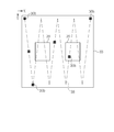
- the position of the AEC pixel 30 b in the Y direction is changed for each second signal line 32 b, whereby the AEC pixels 30 b are uniformly distributed on the imaging surface 33.
- the AEC pixel 30 b is arranged so as to draw a zigzag locus 38 that is symmetrical with respect to the center of the imaging surface 33.
- a lighting field 39 described later is set on the imaging surface 33.
- the above-described control board 21 is provided with a gate driver 40, a signal processing circuit 41, a memory 42, an AEC unit 43, and a control unit 44 for controlling them.
- the gate driver 40 is connected to the end of each scanning line 31.
- the gate driver 40 sequentially applies to each scanning line 31 at the time of “reading operation” for reading out signal charges from the normal pixels 30 a and at the time of “reset operation” for reading out unnecessary charges from the normal pixels 30 a and resetting (discarding) them.
- a gate pulse is applied to turn on the TFT 36 of the normal pixel 30a connected to each scanning line 31.
- the gate driver 40 does not apply a gate pulse to any of the scanning lines 31 during the “accumulation operation” for accumulating signal charges in the normal pixel 30a.
- a signal processing circuit 41 is connected to the end of each signal line 32.
- the signal processing circuit 41 includes an integrating amplifier 45, a gain amplifier 46, a CDS (Correlated Double Sampling) circuit 47, a multiplexer (MUX) 48, and an A / D converter 49.
- the integrating amplifier 45 includes an operational amplifier 45a, a capacitor 45b, and a reset switch 45c, and is provided for each signal line 32.
- the operational amplifier 45a has two input terminals, one of which is connected to the signal line 32 and the other is connected to the ground line.
- the capacitor 45b and the reset switch 45c are connected in parallel between the input terminal to which the signal line 32 of the operational amplifier 45a is connected and the output terminal.
- the integrating amplifier 45 integrates the signal charge input from the signal line 32 by accumulating in the capacitor 45b, and outputs an analog voltage value (signal voltage) corresponding to the integrated value.
- the reset switch 45c is controlled by the control unit 44 and is turned off during integration. By turning on the reset switch 45c, the signal charge accumulated in the capacitor 45b is reset (discarded).
- the gain amplifier 46 is connected to the output terminal of the operational amplifier 45a, and amplifies the signal voltage output from the integrating amplifier 45 by a predetermined gain value. This gain value is set by the control unit 44 based on the shooting conditions.
- the CDS circuit 47 is connected to the output terminal of the gain amplifier 46, performs a known correlated double sampling process on the signal voltage amplified by the gain amplifier 46, and removes noise from the signal voltage.
- the CDS circuit 47 has two sample and hold circuits (not shown) and one difference circuit (not shown).
- One sample and hold circuit samples and holds the signal voltage output from the gain amplifier 46, and the other sample and hold circuit samples the noise signal output from the gain amplifier 46 when the integration amplifier 45 is reset. And hold. By taking the difference between the two by the difference circuit, a signal voltage from which noise has been removed is obtained.
- the MUX 48 is connected to the output terminal of each CDS circuit 47, selects the CDS circuit 47 one by one in order, and serially inputs the signal voltage output from each CDS circuit 47 to the A / D converter 49. .
- the A / D converter 49 performs a known A / D conversion process on the input signal voltage and outputs a digital signal voltage.
- the control unit 44 drives the gate driver 40, the integration amplifier 45, the CDS circuit 47, the MUX 48, and the A / D converter 49 at predetermined cycles, and sequentially selects the scanning lines 31,
- the signal voltage output from the / D converter 49 is sequentially stored in the memory 42.
- the signal voltage for one frame stored in the memory 42 is wirelessly transmitted as image data by the communication unit 23 after correction processing described later is performed by the control unit 44. .
- the integration amplifier 45, the CDS circuit 47, the MUX 48, and the A / D converter 49 are driven at a predetermined sampling period for AEC even during the accumulation operation after the start of imaging (however, The gate driver 40 is not driven), and the output value of the A / D converter 49 is sequentially stored in the memory 42.
- This output value corresponds to the signal charge output from each AEC pixel 30b, and represents an instantaneous value (dose incident in one sampling period) of the X-ray XR incident on the imaging surface 33.
- the AEC unit 43 includes a lighting field setting unit 50, a signal integration unit 51, and a countdown signal generation unit 52.
- the daylighting field setting unit 50 sets a daylighting field 39 (see FIG. 4) for detecting the incident dose of the X-ray XR in the imaging surface 33.
- the daylighting field 39 is a region of interest at the time of diagnosis. For example, when the imaging region is the chest and the lung state is diagnosed, the left and right lung fields are used.
- the lighting field 39 is set based on the inspection order. Further, the daylight field setting unit 50 obtains the one corresponding to the AEC pixel 30 b included in the daylight field 39 from the instantaneous value of the dose stored in the memory 42 and inputs it to the signal integration unit 51.
- the signal integrating unit 51 integrates the instantaneous value for each AEC pixel 30b included in the lighting field 39 to obtain a cumulative dose.
- the countdown signal generation unit 52 obtains an average value of the cumulative dose in the lighting field 39, and predicts the time when the average value of the cumulative dose reaches the target value by performing extrapolation based on the time series of the average value. And a countdown signal is generated.
- an interpolation line L1 is calculated by linearly interpolating the average value of accumulated doses obtained from the accumulation start time (imaging start time) T0 to the current time T1.
- a straight line obtained by extending the insertion line L1 after the current time T1 is defined as an extrapolation line L2.
- an expected arrival time T2 at which the average value of the accumulated dose reaches the target value ST is obtained.
- a difference (remaining time RT) between the estimated arrival time T2 and the current time T1 is obtained, and a countdown signal representing this remaining time RT (for example, 0.1 second) is generated.
- the target value ST is set based on the irradiation dose included in the imaging conditions input from the imaging control device 13.
- the countdown signal generation unit 52 performs the above calculation every time a cumulative dose is input from the signal integration unit 51, and generates a countdown signal.
- the communication unit 23 wirelessly transmits the countdown signal to the imaging control device 13 every time the countdown signal generation unit 52 generates the countdown signal.
- This countdown signal is input to the irradiation stop signal transmission unit 13a as described above, and the irradiation stop signal is transmitted at the time when the remaining time RT becomes zero.
- control unit 44 stops the accumulation operation of the detection panel 20 and generates the image data by performing the above-described reading operation.
- the control unit 44 is provided with a correction processing unit (not shown).
- the correction processing unit performs known offset correction, defective pixel correction, and the like on the image data.
- image data (offset data) is acquired in advance by performing pre-imaging in a non-X-ray irradiation state.
- the offset correction the offset data is subtracted from the image data obtained in the main imaging that performs X-ray irradiation.
- the defective pixel correction the defective pixel is interpolated using the pixel value of the surrounding normal pixel 30a based on the defective pixel information held in advance.
- This defective pixel also includes the AEC pixel 30b, and interpolation processing is performed using the pixel values of the normal pixels 30a around the AEC pixel 30b.
- a communication unit (hereinafter referred to as a first communication unit) 23 of the X-ray image detection apparatus 12 includes a first transmission unit 60, a first reception unit 61, and a first transmission / reception control unit 62.
- the communication unit (hereinafter referred to as a second communication unit) 13b of the imaging control device 13 includes a second transmission unit 70, a second reception unit 71, and a second transmission / reception control unit 72.
- the first communication unit 23 and the second communication unit 13b constitute a wireless communication system 73.
- the first transmission unit 60 includes a known modulation processing unit, amplification unit, and the like (none of which are shown), and a first transmission antenna 60a.
- the first transmission unit 60 modulates the transmission data supplied from the first transmission / reception control unit 62 using the first frequency band f1 (for example, BPSK (Binary Phase Shift Keying)),
- the radio signal 63 is transmitted as a radio signal from the first transmitting antenna 60a.
- a carrier wave (carrier) in the first frequency band f1 is modulated according to transmission data and transmitted.
- the second reception unit 71 includes a well-known demodulation processing unit, amplification unit, and the like (none of which are shown), and a second reception antenna 71a.
- the second receiving antenna 71a can receive radio signals in a predetermined band including the first frequency band f1.
- the second receiving unit 71 receives the first radio wave signal 63 wirelessly transmitted from the first transmitting unit 60 by the second receiving antenna 71a, performs demodulation processing or the like, and reproduces data.
- the second transmission unit 70 includes a known modulation processing unit, amplification unit, and the like (none of which are shown), and a second transmission antenna 70a.
- the second transmission unit 70 modulates transmission data supplied from the second transmission / reception control unit 72 using the second frequency band f2 (for example, BPSK) to form the second radio signal 64, Wireless transmission is performed from the second transmission antenna 70a.
- the carrier wave of the second frequency band f2 is modulated according to the transmission data and transmitted.
- the first reception unit 61 includes a well-known demodulation processing unit, amplification unit, and the like (none of which are shown), and a first reception antenna 61a.
- the first receiving antenna 61a can receive radio signals in a predetermined band including the second frequency band f2.
- the first receiving unit 61 receives the second radio wave signal 64 wirelessly transmitted from the second transmitting unit 70 by the first receiving antenna 61a, performs demodulation processing or the like, and reproduces data.
- the first transmission unit 60 and the second reception unit 71 constitute a first communication pair 65 that transmits data from the X-ray image detection device 12 to the imaging control device 13.
- the second transmission unit 70 and the first reception unit 61 constitute a second communication pair 66 that transmits data from the imaging control device 13 to the X-ray image detection device 12.
- 13 communication channels (frequency channels) CH1 to CH13 are provided at a frequency band of 2.4 GHz at intervals of about 5 MHz.
- One or more communication channels are selected and used from these.
- the occupied frequency bandwidth (wireless LAN channel bandwidth) per channel is about 22 MHz.
- the wireless LAN channel bandwidth can take a range of 10 MHz to 25 MHz.
- the first and second frequency bands f1 and f2 of the present embodiment are set so as to be included in at least one communication channel CHn as shown in FIG.
- the sum of the bandwidth W1 of the first frequency band f1, the bandwidth W2 of the second frequency band f2, and the interval GP between the first frequency band f1 and the second frequency band f2 is Smaller than the wireless LAN channel bandwidth.
- the bandwidth W1, the bandwidth W2, and the interval GP are about 1 MHz to 2 MHz, respectively.
- the bandwidths W1, W2 are preferably between 1 MHz and 5 MHz.
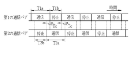
- the first and second communication pairs 65 and 66 alternately repeat communication and stop when performing data transmission. Specifically, the first communication pair 65 alternately repeats the first communication period T1a and the first stop period T1b. The second communication pair 66 alternately repeats the second communication period T2a and the second stop period T2b.
- the first and second communication periods T1a and T2a are periods in which communication links are established in the first and second communication pairs 65 and 66, respectively, and at least carrier waves are transmitted and received.
- the first and second stop periods T1b and T2b are periods in which the communication link is disconnected in the first and second communication pairs 65 and 66, respectively, and transmission and reception of carrier waves are stopped, respectively.
- the first and second frequency bands f1 and f2 are open.
- the first communication period T1a and the second communication period T2a have the same length, and the first stop period T1b and the second stop period T2b have the same length.
- the first stop period T1b is shorter than the first communication period T1a.
- the sum (one period) of the first communication period T1a and the first stop period T1b is preferably in the range of 0.3 msec to 0.5 msec in consideration of transmission / reception of the countdown signal. This is because the operation time of AEC is usually several msec to several hundred msec, and it is desired to perform the stop process in a short time of several msec.
- Each countdown signal has a data amount of about 3 bytes, and can be transmitted and received within one cycle (T1a + T1b).
- the first communication period T1a and the second communication period T2a overlap each other by time Tc. That is, the first transmission / reception control unit 62 transmits the first radio wave signal f1 to the first transmission unit 60 partially overlapping with the period in which the first reception unit 61 receives the second radio wave signal f2. Let The second transmission / reception control unit 72 causes the second transmission unit 70 to transmit the second radio wave signal f2 partially overlapping the period in which the first reception unit 71 receives the first radio wave signal f1. For this reason, at the time of data transmission, at least one of the first and second communication pairs 65 is communicating, and there is no period in which both are stopped.
- the frequency band in the communication channel CHn is changed. There is no period to release. For this reason, when another wireless communication system having a relatively wide frequency band required for one channel performs carrier sense (frequency search), the occupied frequency band and the adjacent frequency band are considered as empty channels. Since the possibility of detection is low, radio wave interference is prevented and stable communication can be performed.
- the first and second communication pairs 65 and 66 transmit data (countdown signal) from the first communication unit 23 of the X-ray image detection device 12 to the second communication unit 13 b of the imaging control device 13.
- the first communication unit 23 transmits a transmission request (RTS: Request13To ⁇ ⁇ Send) signal to the second communication unit 13b.
- RTS transmission request
- CTS reception preparation completion
- the first communication unit 23 When receiving the CTS signal, the first communication unit 23 transmits data (DATA) to the second communication unit 13b.
- the second communication unit 13b When the second communication unit 13b receives the data, the second communication unit 13b transmits a reception completion (ACK) signal to the first communication unit 23. The above sequence is repeated until transmission of data of a predetermined size is completed from the first communication unit 23 to the second communication unit 13b.
- each countdown signal represents the remaining time RT at the time of transmission.
- the first and second communication pairs 65 and 66 stop operating after transmitting / receiving the countdown signal CDn corresponding to zero remaining time RT.
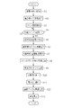
- the operator sets imaging conditions (tube voltage, tube current, X-ray XR irradiation time, etc.) based on the inspection order (step S1). This imaging condition is set for each of the console 14 and the radiation source control device 16.
- the imaging conditions set in the console 14 are wirelessly transmitted from the imaging control device 13 to the X-ray image detection device 12 using the wireless communication system 73 (step S2).
- the X-ray image detection device 12 receives the imaging conditions and the like, it starts the above-described reset operation (step S3).
- This reset operation is an operation (shooting preparation operation) for discharging unnecessary charges from the normal pixel 30a and discarding the accumulated charges of the integration amplifier 45, and is repeated periodically.
- step S5 When the subject H is disposed between the X-ray irradiation apparatus 10 and the X-ray image detection apparatus 12, and the irradiation switch 18b is half-pressed by the operator and then fully pressed (YES determination in step S4), the irradiation switch 18b. Thus, an irradiation start signal is generated (step S5). This irradiation start signal is supplied to the synchronization signal transmitter 16c and the voltage controller 16b of the radiation source controller 16.
- the synchronization signal transmission unit 16 c When the irradiation start signal is input, the synchronization signal transmission unit 16 c generates an imaging start signal and transmits it to the imaging control device 13 via the synchronization signal cable 19. This imaging start signal is wirelessly transmitted from the imaging control device 13 to the X-ray image detection device 12 using the wireless communication system 73 (step S6).
- the voltage control unit 16 b controls the voltage generation unit 16 a to irradiate the subject H with the X-ray XR from the X-ray source 15.
- the X-ray image detection apparatus 12 stops the reset operation in response to the input of the imaging start signal, and starts the accumulation operation almost simultaneously with the start of X-ray irradiation (step S7).
- the X-ray image detection apparatus 12 periodically measures the instantaneous value of the incident dose of X-ray XR.
- the signal integration unit 51 integrates instantaneous values for each AEC pixel 30b.
- the countdown signal generator 52 obtains the average value from the accumulated dose of the AEC pixels 30b in the lighting field 39. Based on this time series of average values, as shown in FIG. 6, a countdown signal representing the remaining time RT until the end of irradiation is generated.
- the countdown signal is wirelessly transmitted from the X-ray image detection device 12 to the imaging control device 13 as shown in FIG. 12 (step S8).
- the countdown signal is periodically received, and the irradiation stop signal transmission unit 13 a generates an irradiation stop signal at the time when the remaining time RT becomes zero, and the radiation source control is performed via the synchronization signal cable 19. It is transmitted to the device 16 (step S9).
- the voltage control unit 16b controls the voltage generation unit 16a to stop the X-ray irradiation from the X-ray source 15 (step S9). Note that when the irradiation stop signal is not input from the imaging control device 13, the radiation source control device 16 stops the irradiation of the X-ray XR based on a preset irradiation time.
- a read operation is performed following the end of the accumulation operation (step S11).
- image data is generated, and the image data is subjected to offset correction and defective pixel correction by the control unit 44, and then the first and second communication from the X-ray image detection device 12 to the imaging control device 13.
- Wireless transmission is performed using the pairs 65 and 66 (step S6).
- the image data transmitted to the imaging control device 13 is transferred to the console 14 and subjected to image processing such as gamma correction and frequency processing, and then displayed on the display 14a (step S13).
- every time data (DATA) is transmitted / received between the first communication unit 23 and the second communication unit 13b, the RTS signal and the CTS signal are transmitted.
- transmission / reception is performed, as shown in FIG. 14, only transmission / reception of data and an ACK signal may be repeated until the final data is transmitted / received after the RTS signal and the CTS signal are transmitted / received once.
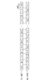
- the countdown signals CD1 to CDn are transmitted and received, as shown in FIG.
- the first communication pair 65 transmits and receives the RTS signal
- the second communication pair 66 transmits and receives the CTS signal
- the first communication Transmission / reception of the countdown signal by the pair 65 and the ACK signal by the second communication pair 66 are repeatedly performed.
- the first and second frequency bands f1 and f2 used by the wireless communication system 73 are fixed.
- the first and second frequency bands f1 and f2 are determined according to the type of signal to be transmitted and received. May be changed.
- wireless transmission of the above-described shooting conditions (step S2), wireless transmission of a shooting start signal (step S6), wireless transmission of a countdown signal (step S8), and wireless transmission of image data (step S12) The first and second frequency bands f1 and f2 are changed.
- the first and second transmission / reception control units 62 and 72 function as a frequency changing unit.
- the first and second transmission / reception control units 62 and 72 monitor the communication state (signal level, etc.) of the wireless communication system 73 and control the amplification units of the first and second reception units 61 and 72 to receive signals. It is also preferable to adjust the sensitivity. Moreover, when the 1st and 2nd transmission / reception control parts 62 and 72 change the 1st and 2nd frequency bands f1 and f2 as mentioned above, it is also preferable to change a receiving sensitivity collectively.
- the countdown signal generation unit 52 generates the countdown signal based on the time series of the average value of the cumulative dose corresponding to the plurality of AEC pixels 30b included in the lighting field 39.
- a countdown signal may be generated based on a time series such as the maximum value, mode value, and median value of the accumulated dose corresponding to the plurality of AEC pixels 30b included in the lighting field 39.
- the countdown signal generation unit 52 generates the interpolation line L1 and the extrapolation line L2 by linear interpolation, but generates the interpolation line L1 and the extrapolation line L2 by nonlinear interpolation using a polynomial or the like. May be.
- the daylighting field 39 is set to a region corresponding to the region of interest based on the inspection order, but the pixel values (instantaneous values or cumulative doses of incident doses) of the plurality of AEC pixels 30b are imaged, and the pattern is obtained.
- the daylighting field 39 may be set by specifying a region of interest by recognition or the like.
- a countdown signal indicating the remaining time until the accumulated dose reaches the target value is wirelessly transmitted from the X-ray image detection device 12 to the imaging control device 13.
- the accumulated dose and instantaneous value are controlled by the X-ray image detection device 12. It may be wirelessly transmitted to the device 13.
- the irradiation stop signal transmission unit 13a generates an irradiation stop signal based on the received cumulative dose or instantaneous value.
- the irradiation stop signal transmitter 13a for generating the irradiation stop signal is provided in the imaging control device 13
- the irradiation stop signal transmitter 13a may be provided in the radiation source controller 16.
- the countdown signal wirelessly transmitted from the X-ray image detection device 12 to the imaging control device 13 is transferred from the imaging control device 13 to the radiation source control device 16 via the synchronization signal cable 19.
- the irradiation stop signal transmission unit 13 a may be provided in the X-ray image detection device 12, and the irradiation stop signal may be wirelessly transmitted from the X-ray image detection device 12 to the imaging control device 13.
- the wireless communication system 73 transmits and receives dummy data (random data or fixed data in which meaningless data is enumerated) and the like from the time when the X-ray image detection apparatus 12 receives the imaging start signal, thereby communicating with the communication link. It is preferable to transmit the irradiation stop signal when the irradiation stop signal is generated by the irradiation stop signal transmitter 13a.
- the wireless communication system 73 establishes a communication link after the countdown signal generation unit 52 generates the countdown signal and starts transmission / reception of the countdown signal, but the countdown signal generation unit 52 receives the countdown signal.
- the communication link is established before generation (for example, when the X-ray image detection device 12 receives the imaging start signal), and the communication link is continuously established by transmitting / receiving dummy data or the like until transmission / reception of the countdown signal is started. It is also preferable. Thereby, transmission / reception of the countdown signal can be started without delay.
- the exposure control signal wirelessly transmitted from the X-ray image detection device 12 to the imaging control device 13 may be a dose value (instantaneous value or cumulative dose value) in addition to the countdown signal and the irradiation stop signal.
- wireless communication is performed between the X-ray image detection device 12 and the imaging control device 13 by the wireless communication system 73, but wireless communication is performed between the X-ray image detection device 12 and the X-ray irradiation device 10. Communication may be possible, and an X-ray image detection device 12 may wirelessly transmit an exposure control signal to the X-ray irradiation device 10. In addition, wireless communication may be enabled between the imaging control device 13 and the X-ray irradiation device 10, and an exposure control signal may be wirelessly transmitted from the imaging control device 13 to the X-ray irradiation device 10.
- all data such as exposure control signals and image data are transmitted and received between the X-ray image detection device 12 and the imaging control device 13 using the wireless communication system 73.
- another wireless communication system using a well-known wireless LAN communication standard or the like may be provided, and image data may be transmitted and received by this other wireless communication system.
- the image data is transmitted using a communication channel having a wider bandwidth than that used in the wireless communication system 73, the transmission speed is increased.
- the imaging control device 13 and the console 14 are separated, but the imaging control device 13 and the console 14 may be integrated.
- the incident dose of the X-ray XR to the X-ray image detection device 12 is detected by the AEC pixel 30b provided in the imaging surface 33. Instead of this, the X-ray XR is detected by a known ion chamber (ionization chamber). The dose may be detected.
- the scintillator 25 is disposed on the X-ray incident side of the light detection substrate 26, but the scintillator 25 may be disposed on the opposite side of the light detection substrate 26 from the X-ray incidence side. In this case, the scintillator 25 absorbs the X-ray XR that has passed through the light detection substrate 26 to generate visible light, and the light detection substrate 26 photoelectrically converts the visible light to generate a signal charge.
- the detection panel 20 is an indirect conversion type that converts the X-ray XR into visible light and then converts the visible light into signal charge. It may be a direct conversion type.
- X-rays are used as radiation, but radiation such as gamma rays may be used.
Landscapes
- Engineering & Computer Science (AREA)
- Health & Medical Sciences (AREA)
- Life Sciences & Earth Sciences (AREA)
- Medical Informatics (AREA)
- Pathology (AREA)
- Heart & Thoracic Surgery (AREA)
- Computer Networks & Wireless Communication (AREA)
- Biophysics (AREA)
- High Energy & Nuclear Physics (AREA)
- Signal Processing (AREA)
- Nuclear Medicine, Radiotherapy & Molecular Imaging (AREA)
- Optics & Photonics (AREA)
- Multimedia (AREA)
- Radiology & Medical Imaging (AREA)
- Biomedical Technology (AREA)
- Physics & Mathematics (AREA)
- Molecular Biology (AREA)
- Surgery (AREA)
- Animal Behavior & Ethology (AREA)
- General Health & Medical Sciences (AREA)
- Public Health (AREA)
- Veterinary Medicine (AREA)
- Apparatus For Radiation Diagnosis (AREA)
- Measurement Of Radiation (AREA)
- Radiography Using Non-Light Waves (AREA)
Abstract
安定した無線通信を行うことを可能とする無線通信装置及びシステム、並びに放射線撮影システムを提供する。 放射線撮影システムは、放射線照射装置、放射線画像検出装置、制御装置を備える。放射線画像検出装置は、第1の通信部を有している。制御装置は、第2の通信部を有している。第1の通信部は、第1の周波数帯の第1の電波信号を無線送信する第1の送信部と、第1の周波数帯とは異なる第2の周波数帯の第2の電波信号を受信する第1の受信部と、これらを制御する第1の送受信制御部とを有している。第2の通信部は、第2の電波信号を無線送信する第2の送信部と、第1の電波信号を受信する第2の受信部と、これらを制御する第2の送受信制御部とを有する。第1及び第2の送受信制御部は、第1の電波信号を送受信する第1の通信期間と、第2の電波信号を送受信する第2の通信期間とを、交互に一部重複させて通信を行う。
Description
本発明は、放射線撮影に用いられる無線通信装置及びシステム、並びに放射線撮影システムに関する。
医療分野において、放射線、例えばX線により被写体(患者)を撮影するX線撮影システムが普及している。X線撮影システムは、X線照射装置と、X線撮影装置とを備えている。X線照射装置は、X線を被写体に向けて照射する。X線撮影装置は、X線画像検出装置と、X線画像検出装置を制御する撮影制御装置と、X線画像を表示する機能を備えたコンソールとを有する。X線画像検出装置は、被写体を透過したX線の線量を電気信号に変換して被写体のX線画像を検出する。
X線画像検出装置は、撮影台等に着脱自在な電子カセッテの形態で使用されることが多い。この電子カセッテは、例えばX線フィルム用カセッテが装着される撮影台にも利用可能にするために、バッテリを内蔵し、かつ、画像データや制御信号を、電波により無線送信することを可能とするものが知られている(特開2010-249572号公報、特開2011-153876号公報参照)。
特開2010-249572号公報に記載のX線撮影システムでは、X線画像検出装置とコンソールにそれぞれ無線通信装置が設けられており、これらの無線通信装置により無線通信システムが構成され、X線画像検出装置からコンソールに画像データが無線送信される。無線通信システムの通信方式としては、例えば、IEEE802.11b/g通信規格に準拠した無線LANの通信方式が用いられている。
特開2011-153876号公報に記載のX線撮影システムは、無線通信装置とアクセスポイントとで構成された無線通信システムを備えている。無線通信装置は、X線画像検出装置とX線照射装置とのそれぞれに設けられている。アクセスポイントは、各無線通信装置間の通信を中継する。また、このX線撮影システムは、自動露出制御(AEC:Automatic Exposure Control)機能を備えている。自動露出制御機能は、被写体の被曝線量を適正でかつ最小限に抑えるために、X線画像検出装置において被写体を透過したX線量を検出し、累積X線量が所定値に達した場合に、X線画像検出装置からX線照射装置に露出制御用信号を送信して、X線照射を停止させる機能である。このX線撮影システムでは、無線通信システムにより、X線画像検出装置からX線照射装置に、照射停止信号等の露出制御用信号が無線送信される。
ところで、比較的大規模な医療施設は、複数のX線撮影システムを保有しており、各X線撮影システムは、隣接する複数の撮影室にそれぞれ設置されている場合が多い。偶発的に複数のX線撮影システムで同時に撮影が行われると、各撮影室に設けられた無線通信システムが同時に無線通信を行うために、電波に干渉が生じ、通信が不安定になる恐れがある。
このため、無線LANの通信方式を用いた無線通信システムでは、通信開始時にデータを通信するための通信リンクを確立する際に、周波数サーチ(キャリアセンス)を行って空きチャネル(他の無線通信システムが非使用の通信チャネル)の探索を行い、探索により検出された空きチャネルを使用して通信リンクを確立している。しかし、通信開始時に周波数サーチを行うと、通信リンクが確立するまでに時間が要されるため、迅速にデータを無線送信することができないという問題がある。
この問題に対処するために、特開2010-249572号公報に記載の無線通信システムでは、データを送受信する一対の無線通信部(以下、通信ペアという)が2組(第1及び第2の通信ペア)設けられている。この無線通信システムでは、予め、第2の通信ペアで周波数サーチにより空チャネルを探索して通信リンクを確立し、確立した通信リンクでダミーデータなどの送受信を行うことにより1チャネル分の周波数帯を占有しておく。画像データの送信を開始する際には、第2の通信ペアが、通信を停止して占有していた周波数帯を解放するとともに、第1の通信ペアが、第2の通信ペアが解放した周波数帯を使用して通信リンクを確立し、画像データの送信を開始する。このように、特開2010-249572号公報に記載の無線通信システムでは、画像データの送信を開始する際に、周波数サーチを行う必要がないので、迅速なデータ送信が可能である。
しかしながら、特開2010-249572号公報に記載の無線通信システムでは、第1の通信ペアは、第2の通信ペアが占有していた周波数帯を引き継ぐが、第2の通信ペアから第1の通信ペアに周波数帯を引き渡す際に、第2の通信ペアが一旦通信を停止して周波数帯を解放するため、解放された周波数帯が、他の無線通信システムにより周波数サーチによって空きチャネルとして検出されて、占有されてしまう可能性がある。
この場合、第1の通信ペアが、他の無線通信システムにより占有された周波数帯と同じ周波数帯を使用すると電波干渉が発生して安定した通信を行うことができない。通信が安定しないとデータの再送が必要になり、データ送信に遅延が生じてしまう。さらに、データの再送を何度も行うことにより、無駄に電力を消費してしまう。
また、X線撮影システムでは、通信の安定性が特に要求される。例えば、特開2011-153876号公報に記載のX線撮影システムでは、データとして露出制御用信号が送信されるが、通信が安定しないと露出制御用信号の送信が遅延して、照射停止タイミングが遅れる。照射停止タイミングが遅れると、X線画像の適正な露出制御が行われないだけでなく、被写体に必要以上のX線が照射されて過剰に被曝してしまう。
また、特開2010-249572号公報に記載のX線撮影システムでは、データとして画像データが送信されるが、X線画像は高精細化が進んでおりデータサイズが大きいので、通信が安定していない状態で画像データを送信すると、データの再送回数が多くなり、多くの電力を消費してしまう。これは、バッテリ駆動の電子カセッテでは、特に問題である。
本発明は、安定した無線通信が可能な無線通信装置及びシステム、並びに放射線撮影システムを提供することを目的とする。
上記目的を達成するために、本発明の無線通信システムは、放射線撮影システムに用いられるものであって、第1の装置に設けられた第1の通信部と、第2の装置に設けられた第2の通信部とを備える。第1の通信部は、第1の送信部と、第1の受信部と、第1の送受信制御部とを有する。第1の送信部は、第1の周波数帯の第1の電波信号を送信する。第1の受信部は、第1の周波数帯とは異なる第2の周波数帯の第2の電波信号を受信する。第1の送受信制御部は、第1の送信部及び第1の受信部を制御し、第1の受信部が第2の電波信号を受信する期間に一部重複して、第1の送信部に第1の電波信号を送信させる。第2の通信部は、第2の送信部と、第2の受信部と、第2の送受信制御部とを有する。第2の送信部は、第2の電波信号を送信する。第2の受信部は、第1の電波信号を受信する。第2の送受信制御部は、第2の送信部及び第2の受信部を制御し、第2の受信部が第1の電波信号を受信する期間に一部重複して、第2の送信部に第2の電波信号を送信させる。
第1の装置は、放射線画像を検出する放射線画像検出装置であり、第2の装置は、放射線を被写体に照射する放射線照射装置又は放射線画像検出装置を制御する撮影制御装置であり、第1の装置が第1の送信部により送信する第1の電波信号には、放射線画像の露出制御用の信号が含まれることが好ましい。
露出制御用の信号は、放射線の照射を停止すべき照射停止タイミングまでの残り時間を表すカウントダウン信号であることが好ましい。
放射線画像検出装置は、撮像面上に2次元に配置された複数の通常画素と、撮像面上に均一に分布されるように、通常画素に代えて配置された複数の検出画素とを備え、通常画素は放射線画像を検出し、検出画素は放射線量を検出することが好ましい。
放射線画像検出装置は、被写体の放射線撮影中に、各検出画素で放射線量の瞬時値を周期的に計測し、検出画素毎に累積線量を求める信号積算部と、累積線量の平均値を求め、この平均値が目標値に到達するまでの時間を予測してカウントダウン信号を算出するカウントダウン信号生成部とを有することが好ましい。
第1の電波信号を送受信する第1の通信期間と、第2の電波信号を送受信する第2の通信期間とは、それぞれ同一周期で繰り返され、該周期は、0.3msec~0.5msecであることが好ましい。
第1の周波数帯の帯域幅と、第2の周波数帯の帯域幅、第1の周波数帯と第2の周波数帯との間隔との合計が、無線LANの通信規格で規定される1チャネルあたりの無線LANチャネル帯域幅より小さいことが好ましい。
第1及び第2の周波数帯は、無線LANチャネル帯域幅の範囲内でそれぞれ設定されることが好ましい。この無線LANチャネル帯域幅は、10MHz~25MHzであることが好ましい。第1及び第2の周波数帯の帯域幅は、1MHz~5MHzであることが好ましい。
第1の送受信制御部は、第1の周波数帯の変更が可能であり、第2の送受信制御部は、第2の周波数帯の変更が可能であることが好ましい。
第1及び第2の送受信制御部は、第1及び第2の受信部の受信感度をそれぞれ制御可能であることが好ましい。
本発明の放射線撮影システムは、被写体に放射線を照射する放射線照射装置と、放射線により被写体の放射線画像を検出する放射線画像検出装置と、放射線画像検出装置を制御する撮影制御装置とを備え、放射線画像検出装置、撮影制御装置、及び放射線照射装置のいずれか1組の装置に設けられた第1及び第2の通信部の間で無線通信を行う。第1の通信部は、第1の送信部と、第1の受信部と、第1の送受信制御部とを有する。第1の送信部は、第1の周波数帯の第1の電波信号を送信する。第1の受信部は、第1の周波数帯とは異なる第2の周波数帯の第2の電波信号を受信する。第1の送受信制御部は、第1の送信部及び第1の受信部を制御し、第1の受信部が第2の電波信号を受信する期間に一部重複して、第1の送信部に第1の電波信号を送信させる。第2の通信部は、第2の送信部と、第2の受信部と、第2の送受信制御部とを有する。第2の送信部は、第2の電波信号を送信する。第2の受信部は、第1の電波信号を受信する。第2の送受信制御部は、第2の送信部及び第2の受信部を制御し、第2の受信部が第1の電波信号を受信する期間に一部重複して、第2の送信部に第2の電波信号を送信させる。
本発明の無線通信装置は、被写体の放射線画像を撮影する放射線撮影システムに用いられるものであって、第1の送信部と、第1の受信部と、第1の送受信制御部とを備える。第1の送信部は、第1の周波数帯の第1の電波信号を送信する。第1の受信部は、第1の周波数帯とは異なる第2の周波数帯の第2の電波信号を受信する。第1の送受信制御部は、第1の送信部及び第1の受信部を制御し、第1の受信部が第2の電波信号を受信する期間に一部重複して、第1の送信部に第1の電波信号を送信させる。
本発明によれば、電波信号を受信する期間に一部重複して、周波数帯の異なる電波信号を送信させるので、他の無線通信システムによるキャリアセンスにより空チャネルとして検出されることが防止され、安定した無線通信を行うことができる。
図1において、X線撮影システム2は、X線照射装置10とX線撮影装置11とを備えている。X線照射装置10は、被写体(患者)Hに向けてX線XRを照射するX線源15と、X線源15の動作を制御する線源制御装置16とを有する。X線撮影装置11は、X線画像検出装置12と、撮影制御装置13と、コンソール14とを有する。
X線画像検出装置12は、可搬型の電子カセッテであり、立位撮影台17に装着される。立位撮影台17は、X線画像検出装置12が着脱自在に取り付けられるスロット(図示せず)を有し、X線XRが入射する入射面12aがX線源15と対向する姿勢でX線画像検出装置12を保持する。被写体Hは、撮影部位がX線照射装置10とX線画像検出装置12との間に位置するように配置される。
コンソール14は、ネットワークを介して接続された病院情報システム(HIS:Hospital Information System)や放射線情報システム(RIS:Radiology Information System)等のオーダ管理システム(図示せず)から検査オーダの入力を受け付ける。検査オーダには、依頼元情報(医師ID、診療科名など)、患者情報(患者名、患者IDなど)、撮影部位(頭部、胸部、腹部など)、撮影方向(正面、側面、斜位など)等が含まれる。
コンソール14は、ディスプレイ14a及びキーボード14bを有している。検査オーダは、オペレータ(放射線技師や医師)がキーボード14b等を用いて直接入力することも可能である。コンソール14に入力された検査オーダは、ディスプレイ14aに表示される。
X線源15は、X線XRを発生するX線管15aと、X線管15aにより発生されたX線XRを被写体Hに照射する照射野を限定する照射野限定器(コリメータ)15bとを有する。X線管15aは、周知のように、フィラメント(陰極)、ターゲット(陽極)、グリッド電極等(いずれも図示せず)で構成されている。線源制御装置16は、X線管15aの各電極に印加する電圧を発生する電圧発生部16aと、この電圧発生部16aで発生する電圧を制御する電圧制御部16bとを有する。
フィラメントは、フィラメントとターゲットとの間に印加される電圧(管電圧)に応じて熱電子を生成し、ターゲットに向けて放出する。グリッド電極は、フィラメントとターゲットとの間に配置されており、印加される電圧により、フィラメントからターゲットに向かう熱電子の流量(管電流)を制御する。ターゲットは、タングステン等で形成されており、熱電子が衝突することによりX線XRを放出する。
照射野限定器15bは、X線XRを遮蔽する4枚の鉛板(図示せず)を四角形の各辺上に配置し、X線XRを通過させる照射開口が中央部に形成したものである。各鉛板の位置を変更することで、照射開口の大きさ及び位置が変化して、X線XRの照射野が変更される。
線源制御装置16には、オペレータが撮影条件を設定するための操作パネル18aと、X線XRの照射を開始するための照射スイッチ18bとが接続されている。撮影条件には、管電圧、管電流、X線XRの照射時間等が含まれる。電圧制御部16bは、操作パネル18aにより設定された撮影条件に基づいて、電圧発生部16aからX線管15aの各電極への印加電圧、及び印加時間を制御する。
撮影条件の設定手順は、例えば、以下のとおりである。検査オーダに含まれる撮影部位などを考慮して、オペレータが撮影条件(管電圧、管電流、X線XRの照射時間など)を判断し、キーボード14bを通じてコンソール14に撮影条件を入力する。コンソール14に入力された撮影条件は、撮影されたX線画像や検査オーダと関連づけて付帯させる付帯情報として利用される。
X線画像検出装置12は、自動露出制御(AEC:Automatic Exposure Control)機能を有している。撮影条件中の照射時間及び管電流は、X線画像検出装置12のAEC機能を使用する場合に、照射線量の目標値の算出に使用される。
線源制御装置16には、オペレータにより、コンソール14に入力した撮影条件と同じ条件が、操作パネル18aを通じて設定される。ただし、AEC機能を使用する場合には、線源制御装置16には、コンソール14に設定した照射時間よりも長い照射時間が設定される。これは、AECでは、X線XRの照射停止タイミングがX線撮影装置11によって決められるので、その照射停止タイミングより前に線源制御装置16によってX線照射が停止されるのを防止するためである。
また、線源制御装置16には、安全規制上許容される最大照射時間がプリセットされている。AEC機能を使用する場合に、線源制御装置16に撮影毎に照射時間の設定を行わずに、プリセットされた最大照射時間を照射時間として設定してもよい。
照射スイッチ18bは、二段押下型であり、一段目まで押下(いわゆる半押し)されるとウォームアップ開始信号を発生し、二段目まで押下(いわゆる全押し)されると照射開始信号を発生する。ウォームアップ開始信号及び照射開始信号は、電圧制御部16bに入力される。
電圧制御部16bは、ウォームアップ開始信号が入力されると、電圧発生部16aを制御して、フィラメントに所定の電圧を印加させて予熱する。このとき、グリッド電極には、フィラメントで発生した熱電子がターゲットに到達しないように、第1の電圧が印加されている。
電圧制御部16bは、照射開始信号が入力されると、電圧発生部16aを制御して、ターゲットに管電圧の設定値に応じた電圧を印加させた後、グリッド電極に管電流の設定値に応じた第2の電圧を印加させる。これにより、フィラメントで発生した熱電子がターゲットに衝突してX線XRが放出される。フィラメントの予熱は、照射開始信号の入力(グリッド電極への第2の電圧の印加)と同時に、X線XRを安定して放出させるために行われている。
また、電圧制御部16bは、AEC機能により撮影制御装置13から入力される照射停止信号に基づいて、X線XRの放出を停止する。具体的には、電圧制御部16bは、照射停止信号が入力されると、グリッド電極を第2の電圧から第1の電圧に切り替え、続いてターゲットに対する電圧印加を停止し、最後にフィラメントに対する電圧印加を停止する。また、電圧制御部16bは、撮影制御装置13から照射停止信号が入力されないまま、操作パネル18aにより設定された照射時間や、プリセットされた最大照射時間が経過(タイムアウト)した場合においても、電圧制御部16bを制御し、X線XRの放出を停止させる。
線源制御装置16は、撮影制御装置13と同期信号ケーブル19を介して接続されており、同期信号送信部16cを有する。同期信号送信部16cは、X線源15の照射開始タイミングとX線画像検出装置1の撮影開始タイミングとを同期させるために、照射スイッチ18bから照射開始信号が入力されると、同期信号ケーブル19を介して、撮影制御装置13に撮影開始信号を送信する。
撮影制御装置13とX線画像検出装置12とは無線通信を行う。撮影制御装置13は、線源制御装置16から撮影開始信号が入力されると、この撮影開始信号をX線画像検出装置12に無線送信する。X線画像検出装置12は、撮影開始信号が入力されるとX線検出動作を開始する。
X線画像検出装置12は、コンソール14により設定された管電流とX線XRの照射時間との積で表される照射線量(いわゆるmAs値)を、撮影制御装置13から取得する。X線画像検出装置12は、X線検出動作を開始するとともに、AEC機能により、X線源15から照射されたX線XRの入射線量を検出し、その累積線量が目標値(照射線量に対応する値)に達するまでの残時間を、一定期間ごとに予測する。この残時間は、カウントダウン信号として一定期間ごとに撮影制御装置13に無線送信される。
撮影制御装置13は、照射停止信号送信部13aと、通信部13bとを有している。照射停止信号送信部13aは、通信部13bを介してX線画像検出装置12から定期的に入力されるカウントダウン信号を取得する。照射停止信号送信部13aは、取得したカウントダウン信号に基づき、残時間がゼロとなる時刻を事前に予測し、その時刻に照射停止信号を、同期信号ケーブル19を介して線源制御装置16に送信する。予測時刻は、最新のカウントダウン信号に基づいて再計算され更新される。照射停止信号送信部13aは、カウントダウン信号を取得するたびに停止時刻を予測するので、X線検出動作中に、X線画像検出装置12からのカウントダウン信号の送信が万が一途絶えた場合でも、受信済みのカウントダウン信号に基づいて照射停止信号を生成して送信することができる。
X線画像検出装置12は、累積線量が目標値に達するとX線検出動作を終了し、画像データを生成して撮影制御装置13に無線送信する。撮影制御装置13は、X線画像検出装置12から送信された画像データを受信して、コンソール14に転送する。
コンソール14は、撮影制御装置13に対して撮影条件を送信するとともに、撮影制御装置13から送信される画像データに対して、ガンマ補正、周波数処理等の各種画像処理を施す。画像処理済みの画像データは、ディスプレイ14aに画像表示される他、コンソール14とネットワークを介して接続された画像サーバ(図示せず)等に保存される。この画像データは、撮影条件や患者情報などの情報が付帯情報として付加されて、DICOM(Digital Imaging and COmmunication in Medicine)などの医用画像フォーマットのファイルに変換された上で保存される。
図2において、X線画像検出装置12は、検出パネル20と、制御基板21と、バッテリ22と、通信部23と、これらを収納する筐体24とを有する。筐体24は、偏平な矩形状であり、サイズは、例えば、従来のフイルムカセッテやIP(Imaging Plate)カセッテと同一である。このため、X線画像検出装置12は、フイルムカセッテ用やIPカセッテ用の既存の撮影台にも取り付け可能である。筐体24は、カーボン等のX線透過性材料で形成されている。
バッテリ22は、電源回路(図示せず)を通じてX線画像検出装置12の各部に電力を供給する。バッテリ22は、筐体24内から外部に取り出し可能であり、専用の充電器(図示せず)にセットして充電することが可能である。
通信部23は、撮影制御装置13との間で、各種信号(前述の撮影開始信号、カウントダウン信号、撮影条件等)や、画像データを送受信する。
検出パネル20は、シンチレータ(蛍光体)25と、光検出基板26とを有する。シンチレータ25と光検出基板26は、X線XRの入射面12a側からこの順に積層されている。シンチレータ25は、CsI:Tl(タリウム賦活ヨウ化セシウム)やGd2O2S:Tb(テルビウム賦活酸硫化ガドリニウム)等の蛍光体を有し、入射したX線XRを可視光に変換して放出する。
光検出基板26は、シンチレータ25から放出された可視光を検出して電気信号に変換する。制御基板21は、光検出基板26を制御するとともに、光検出基板26により生成された電気信号に基づいて画像データの生成を行う。
図3において、光検出基板26は、ガラス基板(図示せず)の片面を撮像面33とし、この上に複数の画素30と、複数の走査線31と、複数の信号線32とを設けたものである。走査線31は、X方向に延伸し、かつY方向に所定のピッチで配置されている。信号線32は、Y方向に延伸し、かつX方向に所定のピッチで配置されている。走査線31と信号線32とは交差しており、各交差点に対応して画素30が設けられている。画素30は、n行×m列(例えば、1024行×1024列)の2次元マトリクスに配列されている。
各画素30は、光電変換素子としてのフォトダイオード35と、スイッチング素子としてのTFT(Thin-Film Transistor)36とを備える。フォトダイオード35は、可視光の入射によって、その入射量に応じた量の電子・正孔対を発生する半導体層(図示せず)と、その上下に配置された上部電極及び下部電極(図示せず)とを有する。TFT36は、ゲート電極が走査線31に接続され、ソース電極が信号線32に接続され、ドレイン電極がフォトダイオード35に接続されている。
具体的には、フォトダイオード35は、下部電極にTFT36が接続されており、上部電極にバイアス線(図示せず)が接続されている。半導体層は、例えば、PIN型であり、上部電極側にN型層、下部電極側にP型層が形成されている。バイアス線には正電圧が印加され、フォトダイオード35は、逆バイアスの状態で使用される。可視光の入射により半導体層で電子・正孔対が発生すると、電子は上部電極に移動してバイアス線に吸収され、正孔は、下部電極に移動して信号電荷として収集される。このため、下部電極は、画素30毎に信号電荷を収集するための画素収集電極と呼ばれる。
画素30は、画像検出用の通常画素30aと、X線照射線量検出用のAEC画素(検出画素)30bとに分けられる。AEC画素30bのTFT36は、ソース電極とドレイン電極とが短絡線37により接続されて短絡している。通常画素30aのTFT36のソース・ドレイン電極間は、短絡していない。
AEC画素30bでは、TFT36は、ソース・ドレイン電極間が短絡していることにより、ゲート電極の印加電圧に関わらず常時オン状態であり、画素収集電極に収集された信号電荷は、短絡線37を介して信号線32に流出する。一方、通常画素30aでは、画素収集電極に収集された信号電荷は、TFT36のゲート電極の印加電圧に応じて信号線32に読み出される。
AEC画素30bは、TFT36を設けずに、フォトダイオード35を信号線32に直接接続することにより構成することも可能であるが、本実施形態では、通常画素30aとAEC画素30bとで構造及び特性に差異が生じないように、通常画素30aと同様にTFT36を設けた上で、ソース・ドレイン電極間を短絡線37で短絡することにより、AEC画素30bを形成している。
AEC画素30bの数は、全画素30の数に対して、数百万分の1から数百分の1程度である。信号線32は、1つのAEC画素30bと複数の通常画素30aが接続された第1の信号線32aと、通常画素30aのみが接続された第2の信号線32bとに分けられる。第1の信号線32aは、1~3本程度(本実施形態では2本)の第2の信号線32bを挟んで、周期的に設けられている。
AEC画素30bのY方向の位置は、第2の信号線32b毎に変更され、それによりAEC画素30bは撮像面33に均一に分布している。例えば、図4に示すように、AEC画素30bは、撮像面33の中心に関して左右対称なジグザクの軌跡38を描くように配置されている。撮像面33には、後述する採光野39が設定される。
前述の制御基板21には、ゲートドライバ40と、信号処理回路41と、メモリ42と、AEC部43と、これらを制御する制御部44とが設けられている。ゲートドライバ40は、各走査線31の端部に接続されている。このゲートドライバ40は、通常画素30aから信号電荷を読み出す「読み出し動作」時と、通常画素30aから不要電荷を読み出してリセット(破棄)する「リセット動作」時とにおいて、各走査線31に順次にゲートパルスを与え、各走査線31に接続された通常画素30aのTFT36をオン状態とする。ゲートドライバ40は、通常画素30aに信号電荷を蓄積する「蓄積動作」時には、いずれの走査線31にもゲートパルスを与えない。
各信号線32の端部には、信号処理回路41が接続されている。信号処理回路41は、積分アンプ45と、ゲインアンプ46と、CDS(Correlated Double Sampling)回路47と、マルチプレクサ(MUX)48と、A/D変換器49とを有する。積分アンプ45は、オペアンプ45a、キャパシタ45b、及びリセットスイッチ45cを有し、各信号線32ごとに設けられている。
オペアンプ45aは、2つの入力端子を有し、一方に信号線32が接続されており、他方にグランド線が接続されている。キャパシタ45b及びリセットスイッチ45cは、オペアンプ45aの信号線32が接続された入力端子と、出力端子との間に並列して接続されている。
積分アンプ45は、信号線32から入力される信号電荷をキャパシタ45bに蓄積することにより積算し、積算値に対応するアナログの電圧値(信号電圧)を出力する。リセットスイッチ45cは、制御部44により制御され、積算時にはオフ状態とされる。リセットスイッチ45cをオン状態とすることで、キャパシタ45bに蓄積された信号電荷がリセット(破棄)される。
ゲインアンプ46は、オペアンプ45aの出力端子に接続されており、積分アンプ45から出力された信号電圧を、所定のゲイン値により増幅する。このゲイン値は、制御部44により撮影条件に基づいて設定される。
CDS回路47は、ゲインアンプ46の出力端子に接続されており、ゲインアンプ46により増幅された信号電圧に対して周知の相関二重サンプリング処理を施し、信号電圧からノイズを除去する。具体的には、CDS回路47は、2つのサンプルホールド回路(図示せず)と、1つの差分回路(図示せず)とを有している。一方のサンプルホールド回路で、ゲインアンプ46から出力される信号電圧をサンプルして保持し、他方のサンプルホールド回路で、積分アンプ45がリセットされた際にゲインアンプ46から出力されるノイズ信号をサンプルして保持する。差分回路で両者の差分を取ることにより、ノイズが除去された信号電圧が得られる。
MUX48は、各CDS回路47の出力端子に接続されており、CDS回路47を1つずつ順番に選択し、A/D変換器49に各CDS回路47から出力される信号電圧をシリアルに入力する。A/D変換器49は、入力された信号電圧に対して、周知のA/D変換処理を行い、デジタルの信号電圧を出力する。
制御部44は、読み出し動作時には、ゲートドライバ40、積分アンプ45、CDS回路47、MUX48、A/D変換器49を、それぞれ所定の周期で駆動し、走査線31を順次に選択しながら、A/D変換器49から出力された信号電圧を、メモリ42に順次に記憶させる。1フレーム分の読み出し動作が終了すると、メモリ42に記憶された1フレーム分の信号電圧は、制御部44により後述する補正処理が行われた後、画像データとして、通信部23により無線送信される。
本実施形態では、撮影開始後の蓄積動作中においても、AECのために、積分アンプ45、CDS回路47、MUX48、A/D変換器49が、所定のサンプリング周期で駆動されており(ただし、ゲートドライバ40は駆動されていない)、A/D変換器49の出力値が、メモリ42に順次記憶される。この出力値は、各AEC画素30bから出力される信号電荷に対応し、撮像面33に入射するX線XRの線量の瞬時値(1サンプリング周期に入射する線量)を表す。
図5において、AEC部43は、採光野設定部50と、信号積算部51と、カウントダウン信号生成部52とを有する。採光野設定部50は、撮像面33内に、X線XRの入射線量を検出する採光野39(図4参照)を設定する。この採光野39は、診断時の関心領域であり、例えば、撮影部位が胸部で、肺の状態を診断する場合には、左右の肺野である。採光野39は、検査オーダに基づいて設定される。また、採光野設定部50は、メモリ42に記憶された線量の瞬時値から、採光野39に含まれるAEC画素30bに対応するものを取得して、信号積算部51に入力する。
信号積算部51は、採光野設定部50から瞬時値が入力されるたびに、採光野39に含まれるAEC画素30bごとに、瞬時値を積算して累積線量を求める。カウントダウン信号生成部52は、採光野39内の累積線量の平均値を求め、この平均値の時系列に基づいて、外挿演算を行うことにより累積線量の平均値が目標値に達する時刻を予想し、カウントダウン信号を生成する。
具体的には、図6に示すように、まず、蓄積開始時刻(撮影開始時刻)T0から現時刻T1までに得られた累積線量の平均値を線形補間することにより内挿線L1を算出し、この内挿線L1を現時刻T1以降に延伸させた直線を外挿線L2とする。この外挿線L2に基づき、累積線量の平均値が目標値STに達する到達予想時刻T2を求める。そして、到達予想時刻T2と現時刻T1との差(残時間RT)を求め、この残時間RT(例えば、0.1秒)を表すカウントダウン信号を生成する。目標値STは、撮影制御装置13から入力される撮影条件に含まれる照射線量に基づいて設定される。
カウントダウン信号生成部52は、信号積算部51から累積線量が入力されるたびに、上記演算を行い、カウントダウン信号を生成する。通信部23は、カウントダウン信号生成部52によりカウントダウン信号が生成されるたびに、これを撮影制御装置13に無線送信する。このカウントダウン信号は、前述のように照射停止信号送信部13aに入力され、残時間RTがゼロとなる時刻に照射停止信号が送信される。
制御部44は、残時間RTがゼロとなると、検出パネル20の蓄積動作を停止させ、前述の読み出し動作を行わせることにより、画像データを生成する。
制御部44には、補正処理部(図示せず)が設けられている。補正処理部は、画像データに対して、周知のオフセット補正、欠陥画素補正等を行う。オフセット補正のために、X線非照射の状態でプレ撮影を行うことにより画像データ(オフセットデータ)を予め取得する。オフセット補正では、X線照射を行う本撮影で得られた画像データからオフセットデータを減算する。欠陥画素補正では、予め保持している欠陥画素情報に基づき、欠陥画素を、その周囲の通常画素30aの画素値を用いて補間する。この欠陥画素には、AEC画素30bも含まれており、AEC画素30bの周囲の通常画素30aの画素値を用いて補間処理が行われる。
図7において、X線画像検出装置12の通信部(以下、第1の通信部という)23は、第1の送信部60と、第1の受信部61と、第1の送受信制御部62とを有する。同様に、撮影制御装置13の通信部(以下、第2の通信部という)13bは、第2の送信部70と、第2の受信部71と、第2の送受信制御部72とを有する。第1の通信部23と第2の通信部13bが無線通信システム73を構成している。
第1の送信部60は、周知の変調処理部、増幅部等(いずれも図示せず)と、第1の送信アンテナ60aとを有する。この第1の送信部60は、第1の送受信制御部62から供給される送信データを、第1の周波数帯f1を用いて変調(例えば、BPSK(Binary Phase Shift Keying))して第1の電波信号63とし、第1の送信アンテナ60aから無線送信する。具体的には、第1の周波数帯f1の搬送波(キャリア)を、送信データに応じて変調して送信する。
第2の受信部71は、周知の復調処理部、増幅部等(いずれも図示せず)と、第2の受信アンテナ71aとを有する。第2の受信アンテナ71aは、第1の周波数帯f1を含む所定帯域の電波信号を受信可能である。この第2の受信部71は、第1の送信部60から無線送信された第1の電波信号63を第2の受信アンテナ71aで受信し、復調処理等を行ってデータを再生する。
同様に、第2の送信部70は、周知の変調処理部、増幅部等(いずれも図示せず)と、第2の送信アンテナ70aとを有する。この第2の送信部70は、第2の送受信制御部72から供給される送信データを、第2の周波数帯f2を用いて変調(例えば、BPSK)して第2の電波信号64とし、第2の送信アンテナ70aから無線送信する。具体的には、第2の周波数帯f2の搬送波(キャリア)を、送信データに応じて変調して送信する。
第1の受信部61は、周知の復調処理部、増幅部等(いずれも図示せず)と、第1の受信アンテナ61aとを有する。第1の受信アンテナ61aは、第2の周波数帯f2を含む所定帯域の電波信号を受信可能である。この第1の受信部61は、第2の送信部70から無線送信された第2の電波信号64を第1の受信アンテナ61aで受信し、復調処理等を行ってデータを再生する。
第1の送信部60と第2の受信部71とは、X線画像検出装置12から撮影制御装置13にデータ送信を行う第1の通信ペア65を構成している。第2の送信部70と第1の受信部61とは、撮影制御装置13からX線画像検出装置12にデータ送信を行う第2の通信ペア66を構成している。
図8に示すように、一般的なIEEE802.11b/g通信規格準拠の無線LANでは、2.4GHz帯の周波数帯域に約5MHzの間隔で、13個の通信チャネル(周波数チャネル)CH1~CH13が割り当てられており、これらから1以上の通信チャネルが選択されて使用される。1チャネルあたりの占有周波数帯域幅(無線LANチャネル帯域幅)は、約22MHzである。この他にも、無線LANには、IEEE802.11a/n通信規格等も存在するので、無線LANチャネル帯域幅は、10MHz~25MHzの範囲を取り得る。
本実施形態の第1及び第2の周波数帯f1,f2は、図9に示すように、少なくとも1つの通信チャネルCHn内に含まれるように設定される。具体的には、第1の周波数帯f1の帯域幅W1と、第2の周波数帯f2の帯域幅W2と、第1の周波数帯f1と第2の周波数帯f2との間隔GPとの合計が、無線LANチャネル帯域幅より小さい。例えば、帯域幅W1、帯域幅W2、間隔GPは、それぞれ約1MHz~2MHzである。帯域幅W1,W2は、1MHz~5MHzの間であることが好ましい。
図10において、第1及び第2の通信ペア65,66は、データ送信を行う際には、通信と停止とを交互に繰り返す。具体的には、第1の通信ペア65は、第1の通信期間T1aと第1の停止期間T1bとを交互に繰り返す。第2の通信ペア66は、第2の通信期間T2aと第2の停止期間T2bとを交互に繰り返す。
第1及び第2の通信期間T1a,T2aは、それぞれ第1及び第2の通信ペア65,66において通信リンクが確立されている期間であり、少なくとも搬送波が送受信されている。これに対して、第1及び第2の停止期間T1b,T2bは、それぞれ第1及び第2の通信ペア65,66において通信リンクが切断されている期間であり、搬送波の送受信が停止され、それぞれ第1及び第2の周波数帯f1,f2が開放されている。
本実施形態では、第1の通信期間T1aと第2の通信期間T2aとは同じ長さであり、第1の停止期間T1bと第2の停止期間T2bとは同じ長さである。また、第1の停止期間T1bは、第1の通信期間T1aより短い。
第1の通信期間T1aと第1の停止期間T1bとの和(1周期)は、カウントダウン信号の送受信を考慮して、0.3msec~0.5msecの範囲内であることが好ましい。これは、通常、AECの動作時間は、数msec~数100msecであり、停止処理を数msecの短時間で行うことが望まれるためである。各カウントダウン信号は、データ量が3バイト程度であり、この1周期(T1a+T1b)内に送受信可能である。
第1の通信期間T1aと、第2の通信期間T2aとは、時間Tcだけ重複している。すなわち、第1の送受信制御部62は、第1の受信部61が第2の電波信号f2を受信する期間に一部重複して、第1の送信部60に第1の電波信号f1を送信させる。第2の送受信制御部72は、第1の受信部71が第1の電波信号f1を受信する期間に一部重複して、第2の送信部70に第2の電波信号f2を送信させる。このため、データ送信時には、第1及び第2の通信ペア65の少なくともいずれか1つが通信しており、両方が停止している期間は存在しない。
このように、データ送信時には、無線LANにおける1つの通信チャネルCHn内で、第1及び第2の通信ペア65のいずれかが常に周波数帯域を占有しているため、通信チャネルCHn内の周波数帯を解放する期間はない。このため、1チャネルに必要な周波数帯が相対的に広帯域な他の無線通信システムがキャリアセンス(周波数サーチ)を行ったときに、占有している周波数帯とそれに近接した周波数帯が空きチャネルとして検出される可能性が低いので、電波干渉が防止され安定した通信を行うことができる。
図11において、第1及び第2の通信ペア65,66は、例えば、X線画像検出装置12の第1の通信部23から撮影制御装置13の第2の通信部13bに、データ(カウントダウン信号や画像データ等)を送信する場合には、まず、第1の通信部23は、第2の通信部13bに、送信要求(RTS:Request To Send)信号を送信する。第2の通信部13bは、RTS信号を受信すると、第1の通信部23に、受信準備完了(CTS:Clear To Send)信号を送信する。
第1の通信部23は、CTS信号を受信すると、第2の通信部13bにデータ(DATA)を送信する。第2の通信部13bは、データを受信すると、第1の通信部23に受信完了(ACK)信号を送信する。以上のシーケンスは、第1の通信部23から第2の通信部13bに、所定サイズのデータの送信が完了するまで繰り返し行われる。
逆に、第2の通信部13bから第1の通信部23に、データ(撮影開始信号や撮影条件等)を送信する場合には、第1及び第2の通信ペア65,66は、上記とは逆の動作を行う。
具体的に、X線画像検出装置12から撮影制御装置13に、前述のカウントダウン信号を送信する場合には、図12に示すように、複数のカウントダウン信号CD1~CDnを順に送信する。各カウントダウン信号は、送信時点での残時間RTを表している。第1及び第2の通信ペア65,66は、残時間RTがゼロに対応するカウントダウン信号CDnを送受信後、動作を停止する。
次に、以上のように構成されたX線撮影システム2の作用を、図13のフローチャートに沿って説明する。まず、コンソール14が検査オーダを受信すると、オペレータにより、検査オーダに基づき、撮影条件(管電圧、管電流、X線XRの照射時間等)が設定される(ステップS1)。この撮影条件は、コンソール14と線源制御装置16とのそれぞれに設定される。
コンソール14に設定された撮影条件は、撮影制御装置13からX線画像検出装置12に、無線通信システム73を用いて無線送信される(ステップS2)。X線画像検出装置12は、撮影条件等を受信すると、前述のリセット動作を開始する(ステップS3)。このリセット動作は、通常画素30aからの不要電荷の排出と、積分アンプ45の蓄積電荷の破棄とを行う動作(撮影準備動作)であり、周期的に繰り返し行われる。
被写体HをX線照射装置10とX線画像検出装置12との間に配置し、オペレータにより、照射スイッチ18bが半押しされ、その後全押しされると(ステップS4でYES判定)、照射スイッチ18bにより照射開始信号が生成される(ステップS5)。この照射開始信号は、線源制御装置16の同期信号送信部16c及び電圧制御部16bに供給される。
同期信号送信部16cは、照射開始信号が入力されると、撮影開始信号を生成し、同期信号ケーブル19を介して、撮影制御装置13に送信される。この撮影開始信号は、撮影制御装置13からX線画像検出装置12に、無線通信システム73を用いて無線送信される(ステップS6)。
電圧制御部16bは、照射開始信号が入力されると、電圧発生部16aを制御して、X線源15からX線XRを被写体Hに向けて照射させる。このとき、X線画像検出装置12では、撮影開始信号の入力に応じて、リセット動作が停止し、X線照射の開始とほぼ同時に蓄積動作が開始する(ステップS7)。
この蓄積動作が開始すると、X線画像検出装置12では、周期的にX線XRの入射線量の瞬時値の計測が行われる。信号積算部51は、AEC画素30b毎に瞬時値を積算する。カウントダウン信号生成部52は、採光野39内のAEC画素30bの累積線量から、その平均値を求める。この平均値の時系列に基づいて、図6に示すように、照射終了までの残時間RTを表すカウントダウン信号が生成される。このカウントダウン信号は、X線画像検出装置12から撮影制御装置13に、図12に示すように無線送信される(ステップS8)。
撮影制御装置13では、カウントダウン信号を定期的に受信し、照射停止信号送信部13aにより、残時間RTがゼロとなる時刻に照射停止信号が生成され、同期信号ケーブル19を介して、線源制御装置16に送信される(ステップS9)。線源制御装置16は、照射停止信号を受信すると、電圧制御部16bが電圧発生部16aを制御して、X線源15からのX線照射を停止させる(ステップS9)。なお、線源制御装置16は、撮影制御装置13から照射停止信号が入力されない場合には、予め設定された照射時間に基づいてX線XRの照射を停止させる。
X線画像検出装置12では、蓄積動作の終了に続いて読み出し動作が行われる(ステップS11)。これにより、画像データが生成され、この画像データは、制御部44でオフセット補正及び欠陥画素補正が行われてから、X線画像検出装置12から撮影制御装置13に、第1及び第2の通信ペア65,66を用いて無線送信される(ステップS6)。撮影制御装置13に送信された画像データは、コンソール14に転送され、ガンマ補正、周波数処理等の画像処理が施された後、ディスプレイ14aに画像表示される(ステップS13)。
なお、上記実施形態では、図11に示すように、第1の通信部23と第2の通信部13bとの間で、データ(DATA)を一度送受信するたびに、RTS信号とCTS信号とを送受信しているが、図14に示すように、RTS信号とCTS信号を一度送受信した後、最終のデータが送受信されるまでの間、データとACK信号の送受信のみを繰り返す方式としてもよい。この場合、カウントダウン信号CD1~CDnの送受信時には、図15に示すように、第1の通信ペア65によりRTS信号を送受信し、第2の通信ペア66によりCTS信号を送受信した後、第1の通信ペア65によるカウントダウン信号の送受信と、第2の通信ペア66によるACK信号とが繰り返し行われる。
また、上記実施形態では、無線通信システム73が用いる第1及び第2の周波数帯f1,f2は固定されているが、送受信する信号の種類に応じて第1及び第2の周波数帯f1,f2を変更してもよい。例えば、前述の撮影条件の無線送信(ステップS2)と、撮影開始信号の無線送信(ステップS6)と、カウントダウン信号の無線送信(ステップS8)と、画像データの無線送信(ステップS12)とで、第1及び第2の周波数帯f1,f2をそれぞれ変更する。この場合、第1及び第2の送受信制御部62,72が、周波数変更部として機能する。
無線通信システム73は、第1及び第2の通信ペア65,66のいずれかが送受信に失敗した場合(例えば、送信元が送信先から所定期間内にCTSやACKを受信できない場合)に、その周波数帯(第1及び第2の周波数帯f1,f2のいずれか)を変更して、送受信を再度行うことも好ましい。例えば、第1及び第2の周波数帯f1,f2のうちの一方を変更する場合には、変更前後で、他方の周波数帯との間隔GPが同一とするように変更する。具体的には、f1=2420MHz(中心波長)、f2=2440MHz(中心波長)であって、第2の周波数帯f2を変更する場合には、f2=2400MHz(中心波長)とする。
第1及び第2の送受信制御部62,72は、無線通信システム73の通信状態(信号レベル等)を監視し、第1及び第2の受信部61,72の増幅部を制御して、受信感度を調整することも好ましい。また、第1及び第2の送受信制御部62,72は、前述のように第1及び第2の周波数帯f1,f2を変更する際に、受信感度も併せて変更することも好ましい。
上記実施形態では、カウントダウン信号生成部52は、採光野39内に含まれる複数のAEC画素30bに対応する累積線量の平均値の時系列に基づいてカウントダウン信号を生成しているが、平均値に代えて、採光野39内に含まれる複数のAEC画素30bに対応する累積線量の最大値、最頻値、中央値等の時系列に基づいてカウントダウン信号を生成してもよい。
上記実施形態では、カウントダウン信号生成部52は、線形補間により内挿線L1及び外挿線L2を生成しているが、多項式等を用いた非線形補間により内挿線L1及び外挿線L2を生成してもよい。
上記実施形態では、採光野39を、検査オーダに基づき関心領域に対応する領域に設定しているが、複数のAEC画素30bの画素値(入射線量の瞬時値または累積線量)を画像化し、パターン認識等により関心領域を特定することで、採光野39を設定してもよい。
累積線量が目標値に達するまでの残時間を表すカウントダウン信号がX線画像検出装置12から撮影制御装置13に無線送信されているが、累積線量や瞬時値をX線画像検出装置12から撮影制御装置13に無線送信してもよい。この場合には、照射停止信号送信部13aは、受信した累積線量や瞬時値に基づいて照射停止信号を生成する。
照射停止信号を生成する照射停止信号送信部13aが撮影制御装置13内に設けられているが、照射停止信号送信部13aを線源制御装置16内に設けてもよい。この場合には、X線画像検出装置12から撮影制御装置13に無線送信されたカウントダウン信号は、撮影制御装置13から同期信号ケーブル19を介して線源制御装置16に転送される。
照射停止信号送信部13aをX線画像検出装置12内に設け、X線画像検出装置12から撮影制御装置13に照射停止信号を無線送信してもよい。この場合、無線通信システム73は、X線画像検出装置12が撮影開始信号を受信した時点から、ダミーデータ(意味のないデータを羅列したランダムデータや固定データ)等を送受信することにより、通信リンクを確立しておき、照射停止信号送信部13aにより照射停止信号が生成された際に、照射停止信号を送信することが好ましい。
上記実施形態では、無線通信システム73は、カウントダウン信号生成部52がカウントダウン信号を生成してから通信リンクを確立してカウントダウン信号の送受信を開始しているが、カウントダウン信号生成部52がカウントダウン信号を生成する前(例えば、X線画像検出装置12が撮影開始信号を受信した時点)に通信リンクを確立し、カウントダウン信号の送受信を開始するまで、ダミーデータ等を送受信して通信リンクを確立し続けることも好ましい。これにより、カウントダウン信号の送受信の開始を遅延なく行うことができる。
X線画像検出装置12から撮影制御装置13に無線送信する露出制御用の信号は、カウントダウン信号、照射停止信号の他に、線量値(瞬時値または累積線量値)であってもよい。
上記実施形態では、無線通信システム73により、X線画像検出装置12と撮影制御装置13との間で無線通信を行っているが、X線画像検出装置12とX線照射装置10の間で無線通信を可能とし、X線画像検出装置12からX線照射装置10に露出制御用の信号を無線送信してもよい。また、撮影制御装置13とX線照射装置10との間で無線通信を可能とし、撮影制御装置13からX線照射装置10に露出制御用の信号を無線送信してもよい。
上記実施形態では、X線画像検出装置12と撮影制御装置13との間で、露出制御用の信号や画像データ等の全てのデータを、無線通信システム73を用いて送受信しているが、無線通信システム73に加えて、周知の無線LAN通信規格等を用いた別の無線通信システムを設け、この別の無線通信システムにより画像データを送受信してもよい。この場合には、画像データは、無線通信システム73で用いる帯域幅より広い帯域の通信チャネルを用いて送信されるため、送信速度が高速化される。
上記実施形態では、撮影制御装置13とコンソール14とを別体としているが、撮影制御装置13とコンソール14とを一体としてもよい。
X線画像検出装置12へのX線XRの入射線量は、撮像面33内に設けたAEC画素30bにより検出されているが、これに代えて、周知のイオンチャンバ(電離箱)によりX線XRの線量を検出してもよい。
検出パネル20は、シンチレータ25が光検出基板26のX線入射側に配置されているが、シンチレータ25を光検出基板26のX線入射側とは反対側に配置してもよい。この場合には、シンチレータ25は、光検出基板26を透過したX線XRを吸収して可視光を発生し、光検出基板26は、この可視光を光電変換して信号電荷を生成する。
検出パネル20は、X線XRを可視光に変換してから、この可視光を信号電荷に変換する間接変換型であるが、アモルファスセレン等の光導電膜によりX線XRを直接信号電荷に変換する直接変換型でもよい。
また、上記実施形態では、放射線としてX線を用いているが、γ線等の放射線を用いてもよい。
Claims (14)
- 少なくとも第1及び第2の装置により被写体の放射線画像を撮影する放射線撮影システムに用いられ、前記第1の装置に設けられた第1の通信部と、前記第2の装置に設けられた第2の通信部とにより構成された無線通信システムにおいて、
A.前記第1の通信部は、以下を有する:
第1の周波数帯の第1の電波信号を送信する第1の送信部;
前記第1の周波数帯とは異なる第2の周波数帯の第2の電波信号を受信する第1の受信部;及び
前記第1の送信部及び前記第1の受信部を制御し、前記第1の受信部が前記第2の電波信号を受信する期間に一部重複して、前記第1の送信部に前記第1の電波信号を送信させる第1の送受信制御部;
B.前記第2の通信部は、以下を有する:
前記第2の電波信号を送信する第2の送信部;
前記第1の電波信号を受信する第2の受信部;及び
前記第2の送信部及び前記第2の受信部を制御し、前記第2の受信部が前記第1の電波信号を受信する期間に一部重複して、前記第2の送信部に前記第2の電波信号を送信させる第2の送受信制御部。 - 前記第1の装置は、放射線画像を検出する放射線画像検出装置であり、
前記第2の装置は、前記放射線を被写体に照射する放射線照射装置又は前記放射線画像検出装置を制御する撮影制御装置であり、
前記第1の装置が前記第1の送信部により送信する前記第1の電波信号には、前記放射線画像の露出制御用の信号が含まれる請求の範囲第1項に記載の無線通信システム。 - 前記露出制御用の信号は、前記放射線の照射を停止すべき照射停止タイミングまでの残り時間を表すカウントダウン信号である請求の範囲第2項に記載の無線通信システム。
- 前記放射線画像検出装置は、撮像面上に2次元に配置された複数の通常画素と、前記撮像面上に均一に分布されるように、前記通常画素に代えて配置された複数の検出画素とを備え、
前記通常画素は前記放射線画像を検出し、前記検出画素は放射線量を検出する請求の範囲第3項に記載の無線通信システム。 - 前記放射線画像検出装置は、
前記被写体の放射線撮影中に、前記各検出画素で前記放射線量の瞬時値を周期的に計測し、前記検出画素毎に累積線量を求める信号積算部と、
前記累積線量の平均値を求め、この平均値が目標値に到達するまでの時間を予測して前記カウントダウン信号を算出するカウントダウン信号生成部と、
を有する請求の範囲第4項に記載の無線通信システム。 - 前記第1の電波信号を送受信する第1の通信期間と、前記第2の電波信号を送受信する第2の通信期間とは、それぞれ同一周期で繰り返され、該周期は、0.3msec~0.5msecである請求の範囲第2項に記載の無線通信システム。
- 前記第1の周波数帯の帯域幅と、前記第2の周波数帯の帯域幅、前記第1の周波数帯と前記第2の周波数帯との間隔との合計が、無線LANの通信規格で規定される1チャネルあたりの無線LANチャネル帯域幅より小さい請求の範囲第2項に記載の無線通信システム。
- 前記第1及び第2の周波数帯は、前記無線LANチャネル帯域幅の範囲内でそれぞれ設定される請求の範囲第7項に記載の無線通信システム。
- 前記無線LANチャネル帯域幅は、10MHz~25MHzである請求の範囲第8項に記載の無線通信システム。
- 前記第1及び第2の周波数帯の帯域幅は、1MHz~5MHzである請求の範囲第9項に記載の無線通信システム。
- 前記第1の送受信制御部は、前記第1の周波数帯の変更が可能であり、前記第2の送受信制御部は、前記第2の周波数帯の変更が可能である請求の範囲第2項に記載の無線通信システム。
- 前記第1及び第2の送受信制御部は、前記第1及び第2の受信部の受信感度をそれぞれ制御可能である請求の範囲第2項に記載の無線通信システム。
- 被写体に放射線を照射する放射線照射装置と、前記放射線により前記被写体の放射線画像を検出する放射線画像検出装置と、前記放射線画像検出装置を制御する撮影制御装置とを備え、前記放射線画像検出装置、前記撮影制御装置、及び前記放射線照射装置のいずれか1組の装置に設けられた第1及び第2の通信部の間で無線通信を行う放射線撮影システムにおいて、
A.前記第1の通信部は、以下を有する:
第1の周波数帯の第1の電波信号を送信する第1の送信部;
前記第1の周波数帯とは異なる第2の周波数帯の第2の電波信号を受信する第1の受信部;及び
前記第1の送信部及び前記第1の受信部を制御し、前記第1の受信部が前記第2の電波信号を受信する期間に一部重複して、前記第1の送信部に前記第1の電波信号を送信させる第1の送受信制御部;
B.前記第2の通信部は、以下を有する:
前記第2の電波信号を送信する第2の送信部;
前記第1の電波信号を受信する第2の受信部;及び
前記第2の送信部及び前記第2の受信部を制御し、前記第2の受信部が前記第1の電波信号を受信する期間に一部重複して、前記第2の送信部に前記第2の電波信号を送信させる第2の送受信制御部。 - 被写体の放射線画像を撮影する放射線撮影システムに用いられる無線通信装置において、以下を備える:
第1の周波数帯の第1の電波信号を送信する第1の送信部;
前記第1の周波数帯とは異なる第2の周波数帯の第2の電波信号を受信する第1の受信部;及び
前記第1の送信部及び前記第1の受信部を制御し、前記第1の受信部が前記第2の電波信号を受信する期間に一部重複して、前記第1の送信部に前記第1の電波信号を送信させる第1の送受信制御部。
Applications Claiming Priority (2)
| Application Number | Priority Date | Filing Date | Title |
|---|---|---|---|
| JP2013-024090 | 2013-02-12 | ||
| JP2013024090A JP2014151036A (ja) | 2013-02-12 | 2013-02-12 | 無線通信装置及びシステム、並びに放射線撮影システム |
Publications (1)
| Publication Number | Publication Date |
|---|---|
| WO2014125939A1 true WO2014125939A1 (ja) | 2014-08-21 |
Family
ID=51353948
Family Applications (1)
| Application Number | Title | Priority Date | Filing Date |
|---|---|---|---|
| PCT/JP2014/052246 Ceased WO2014125939A1 (ja) | 2013-02-12 | 2014-01-31 | 無線通信装置及びシステム、並びに放射線撮影システム |
Country Status (2)
| Country | Link |
|---|---|
| JP (1) | JP2014151036A (ja) |
| WO (1) | WO2014125939A1 (ja) |
Families Citing this family (4)
| Publication number | Priority date | Publication date | Assignee | Title |
|---|---|---|---|---|
| JP6711595B2 (ja) * | 2015-11-28 | 2020-06-17 | キヤノン株式会社 | 放射線撮像装置、制御装置、放射線撮像システム、および放射線撮像システムの制御方法 |
| JP6594200B2 (ja) * | 2015-12-28 | 2019-10-23 | キヤノン株式会社 | 放射線撮像システム、通信制御方法及びプログラム |
| JP7212530B2 (ja) * | 2019-01-24 | 2023-01-25 | キヤノン株式会社 | 放射線撮影システム、制御装置および制御方法 |
| JP7799725B2 (ja) * | 2023-05-23 | 2026-01-15 | キヤノン株式会社 | 放射線撮像システムおよび情報処理装置 |
Citations (5)
| Publication number | Priority date | Publication date | Assignee | Title |
|---|---|---|---|---|
| JP2005244837A (ja) * | 2004-02-27 | 2005-09-08 | Sharp Corp | 表示装置 |
| JP2009089739A (ja) * | 2007-10-03 | 2009-04-30 | Toshiba Corp | 乳房撮影検査用x線診断装置 |
| JP2010243486A (ja) * | 2009-03-31 | 2010-10-28 | General Electric Co <Ge> | 無線ディジタル画像検出器 |
| JP2010249572A (ja) * | 2009-04-13 | 2010-11-04 | Konica Minolta Medical & Graphic Inc | 放射線画像生成システム及び放射線画像生成装置 |
| JP2012040315A (ja) * | 2010-08-23 | 2012-03-01 | Fujifilm Corp | 放射線撮影装置、放射線撮影システム、及び放射線検出プログラム |
-
2013
- 2013-02-12 JP JP2013024090A patent/JP2014151036A/ja active Pending
-
2014
- 2014-01-31 WO PCT/JP2014/052246 patent/WO2014125939A1/ja not_active Ceased
Patent Citations (5)
| Publication number | Priority date | Publication date | Assignee | Title |
|---|---|---|---|---|
| JP2005244837A (ja) * | 2004-02-27 | 2005-09-08 | Sharp Corp | 表示装置 |
| JP2009089739A (ja) * | 2007-10-03 | 2009-04-30 | Toshiba Corp | 乳房撮影検査用x線診断装置 |
| JP2010243486A (ja) * | 2009-03-31 | 2010-10-28 | General Electric Co <Ge> | 無線ディジタル画像検出器 |
| JP2010249572A (ja) * | 2009-04-13 | 2010-11-04 | Konica Minolta Medical & Graphic Inc | 放射線画像生成システム及び放射線画像生成装置 |
| JP2012040315A (ja) * | 2010-08-23 | 2012-03-01 | Fujifilm Corp | 放射線撮影装置、放射線撮影システム、及び放射線検出プログラム |
Non-Patent Citations (1)
| Title |
|---|
| KENKO OTA ET AL.: "Performance of Sensor Networks Using ZigBee Wireless Systems", IEICE TECHNICAL REPORT, vol. 109, no. 229, 2009, pages 95 - 100 * |
Also Published As
| Publication number | Publication date |
|---|---|
| JP2014151036A (ja) | 2014-08-25 |
Similar Documents
| Publication | Publication Date | Title |
|---|---|---|
| JP5544383B2 (ja) | 放射線画像検出装置および放射線撮影システム | |
| JP5587356B2 (ja) | 放射線撮影システム、放射線撮影システムの駆動制御方法および駆動制御プログラム、並びに放射線画像検出装置 | |
| EP2564783B1 (en) | Radiographing system, method of controlling automatic exposure in radiographing system, and radiological image detection device | |
| EP2837330B1 (en) | X-ray exposure control device, x-ray image detection apparatus, and x-ray image capturing system | |
| CN103841891B (zh) | 放射线摄影系统及其控制方法以及放射线图像检测装置 | |
| JP5925777B2 (ja) | 放射線画像検出装置及びその制御方法 | |
| JP5749609B2 (ja) | 放射線撮影システム、並びに線源制御装置 | |
| US9025729B2 (en) | Radiation image detecting device and drive control method thereof | |
| EP2564784B1 (en) | Radiographing system, method of controlling automatic exposure in radiographing system, and radiological image detection device | |
| JP5675536B2 (ja) | 放射線撮影システムおよび放射線撮影システムの自動露出制御方法、並びに放射線画像検出装置 | |
| JP2014045938A (ja) | 放射線撮影システムおよびその通信方法、並びに放射線画像検出装置 | |
| WO2014125939A1 (ja) | 無線通信装置及びシステム、並びに放射線撮影システム | |
| JP2006068507A (ja) | フォトタイマーおよび放射線撮影装置 | |
| JP2014195480A (ja) | 放射線画像検出装置及び放射線画像検出装置の制御方法 | |
| JP5428751B2 (ja) | 画像処理装置及び画像処理システム | |
| EP2468188A2 (en) | Portable radiographic image capture device, image capture controller and radiographic image capture system | |
| JP2014050418A (ja) | 放射線撮影システム、放射線発生装置およびその作動方法 | |
| JP2015091321A (ja) | 放射線画像検出装置および放射線の照射開始検出方法 | |
| JP6733184B2 (ja) | 放射線動画像撮影装置 | |
| JP2009082195A (ja) | 放射線変換パネル及び放射線画像撮影方法 | |
| JP2014155511A (ja) | 放射線撮影装置 |
Legal Events
| Date | Code | Title | Description |
|---|---|---|---|
| 121 | Ep: the epo has been informed by wipo that ep was designated in this application |
Ref document number: 14751008 Country of ref document: EP Kind code of ref document: A1 |
|
| NENP | Non-entry into the national phase |
Ref country code: DE |
|
| 122 | Ep: pct application non-entry in european phase |
Ref document number: 14751008 Country of ref document: EP Kind code of ref document: A1 |