WO2014125918A1 - 昇華精製装置及び昇華精製方法 - Google Patents
昇華精製装置及び昇華精製方法 Download PDFInfo
- Publication number
- WO2014125918A1 WO2014125918A1 PCT/JP2014/051799 JP2014051799W WO2014125918A1 WO 2014125918 A1 WO2014125918 A1 WO 2014125918A1 JP 2014051799 W JP2014051799 W JP 2014051799W WO 2014125918 A1 WO2014125918 A1 WO 2014125918A1
- Authority
- WO
- WIPO (PCT)
- Prior art keywords
- sublimation
- tube
- group
- pipe
- sublimation purification
- Prior art date
- Legal status (The legal status is an assumption and is not a legal conclusion. Google has not performed a legal analysis and makes no representation as to the accuracy of the status listed.)
- Ceased
Links
- 0 CC(C(*)C(C)=C(C)C1C)C1=C Chemical compound CC(C(*)C(C)=C(C)C1C)C1=C 0.000 description 2
Images


Classifications
-
- B—PERFORMING OPERATIONS; TRANSPORTING
- B01—PHYSICAL OR CHEMICAL PROCESSES OR APPARATUS IN GENERAL
- B01D—SEPARATION
- B01D7/00—Sublimation
-
- C—CHEMISTRY; METALLURGY
- C07—ORGANIC CHEMISTRY
- C07C—ACYCLIC OR CARBOCYCLIC COMPOUNDS
- C07C221/00—Preparation of compounds containing amino groups and doubly-bound oxygen atoms bound to the same carbon skeleton
-
- C—CHEMISTRY; METALLURGY
- C09—DYES; PAINTS; POLISHES; NATURAL RESINS; ADHESIVES; COMPOSITIONS NOT OTHERWISE PROVIDED FOR; APPLICATIONS OF MATERIALS NOT OTHERWISE PROVIDED FOR
- C09B—ORGANIC DYES OR CLOSELY-RELATED COMPOUNDS FOR PRODUCING DYES, e.g. PIGMENTS; MORDANTS; LAKES
- C09B1/00—Dyes with anthracene nucleus not condensed with any other ring
- C09B1/56—Mercapto-anthraquinones
- C09B1/58—Mercapto-anthraquinones with mercapto groups substituted by aliphatic, cycloaliphatic, araliphatic or aryl radicals
- C09B1/585—Mercapto-anthraquinones with mercapto groups substituted by aliphatic, cycloaliphatic, araliphatic or aryl radicals substituted by aryl radicals
-
- C—CHEMISTRY; METALLURGY
- C09—DYES; PAINTS; POLISHES; NATURAL RESINS; ADHESIVES; COMPOSITIONS NOT OTHERWISE PROVIDED FOR; APPLICATIONS OF MATERIALS NOT OTHERWISE PROVIDED FOR
- C09B—ORGANIC DYES OR CLOSELY-RELATED COMPOUNDS FOR PRODUCING DYES, e.g. PIGMENTS; MORDANTS; LAKES
- C09B19/00—Oxazine dyes
- C09B19/02—Bisoxazines prepared from aminoquinones
-
- C—CHEMISTRY; METALLURGY
- C09—DYES; PAINTS; POLISHES; NATURAL RESINS; ADHESIVES; COMPOSITIONS NOT OTHERWISE PROVIDED FOR; APPLICATIONS OF MATERIALS NOT OTHERWISE PROVIDED FOR
- C09B—ORGANIC DYES OR CLOSELY-RELATED COMPOUNDS FOR PRODUCING DYES, e.g. PIGMENTS; MORDANTS; LAKES
- C09B23/00—Methine or polymethine dyes, e.g. cyanine dyes
- C09B23/02—Methine or polymethine dyes, e.g. cyanine dyes the polymethine chain containing an odd number of >CH- or >C[alkyl]- groups
- C09B23/04—Methine or polymethine dyes, e.g. cyanine dyes the polymethine chain containing an odd number of >CH- or >C[alkyl]- groups one >CH- group, e.g. cyanines, isocyanines, pseudocyanines
-
- C—CHEMISTRY; METALLURGY
- C09—DYES; PAINTS; POLISHES; NATURAL RESINS; ADHESIVES; COMPOSITIONS NOT OTHERWISE PROVIDED FOR; APPLICATIONS OF MATERIALS NOT OTHERWISE PROVIDED FOR
- C09B—ORGANIC DYES OR CLOSELY-RELATED COMPOUNDS FOR PRODUCING DYES, e.g. PIGMENTS; MORDANTS; LAKES
- C09B23/00—Methine or polymethine dyes, e.g. cyanine dyes
- C09B23/10—The polymethine chain containing an even number of >CH- groups
- C09B23/105—The polymethine chain containing an even number of >CH- groups two >CH- groups
-
- C—CHEMISTRY; METALLURGY
- C09—DYES; PAINTS; POLISHES; NATURAL RESINS; ADHESIVES; COMPOSITIONS NOT OTHERWISE PROVIDED FOR; APPLICATIONS OF MATERIALS NOT OTHERWISE PROVIDED FOR
- C09B—ORGANIC DYES OR CLOSELY-RELATED COMPOUNDS FOR PRODUCING DYES, e.g. PIGMENTS; MORDANTS; LAKES
- C09B23/00—Methine or polymethine dyes, e.g. cyanine dyes
- C09B23/10—The polymethine chain containing an even number of >CH- groups
- C09B23/107—The polymethine chain containing an even number of >CH- groups four >CH- groups
-
- C—CHEMISTRY; METALLURGY
- C09—DYES; PAINTS; POLISHES; NATURAL RESINS; ADHESIVES; COMPOSITIONS NOT OTHERWISE PROVIDED FOR; APPLICATIONS OF MATERIALS NOT OTHERWISE PROVIDED FOR
- C09B—ORGANIC DYES OR CLOSELY-RELATED COMPOUNDS FOR PRODUCING DYES, e.g. PIGMENTS; MORDANTS; LAKES
- C09B57/00—Other synthetic dyes of known constitution
-
- C—CHEMISTRY; METALLURGY
- C09—DYES; PAINTS; POLISHES; NATURAL RESINS; ADHESIVES; COMPOSITIONS NOT OTHERWISE PROVIDED FOR; APPLICATIONS OF MATERIALS NOT OTHERWISE PROVIDED FOR
- C09B—ORGANIC DYES OR CLOSELY-RELATED COMPOUNDS FOR PRODUCING DYES, e.g. PIGMENTS; MORDANTS; LAKES
- C09B57/00—Other synthetic dyes of known constitution
- C09B57/008—Triarylamine dyes containing no other chromophores
-
- C—CHEMISTRY; METALLURGY
- C07—ORGANIC CHEMISTRY
- C07C—ACYCLIC OR CARBOCYCLIC COMPOUNDS
- C07C2603/00—Systems containing at least three condensed rings
- C07C2603/02—Ortho- or ortho- and peri-condensed systems
- C07C2603/04—Ortho- or ortho- and peri-condensed systems containing three rings
- C07C2603/06—Ortho- or ortho- and peri-condensed systems containing three rings containing at least one ring with less than six ring members
- C07C2603/10—Ortho- or ortho- and peri-condensed systems containing three rings containing at least one ring with less than six ring members containing five-membered rings
- C07C2603/12—Ortho- or ortho- and peri-condensed systems containing three rings containing at least one ring with less than six ring members containing five-membered rings only one five-membered ring
- C07C2603/14—Benz[f]indenes; Hydrogenated benz[f]indenes
Definitions
- the present invention relates to a sublimation purification apparatus and a sublimation purification method.
- a sublimation purification device is a device for purifying a target substance by utilizing the property that a substance in a solid state at normal temperature is vaporized under an appropriate temperature and pressure, and is used to purify a chemical substance with high purity. ing.
- a sublimation purification apparatus is used to refine the material to a higher degree.
- a sublimation purification apparatus usually includes a sublimation pipe having a sublimation section in which a purification target is installed and a collection section for collecting the sublimation purification product, a vacuum pump, and a pipe connecting the sublimation pipe and the vacuum pump. Further, a heat source for heating the sublimation part is provided. When the sublimation part is heated by the heat source, the sample is sublimated, and the vaporized material is cooled while flowing to the vacuum pump side, and solidifies when the temperature is below a certain temperature. In order to solidify and collect the target object in the collection unit, a temperature gradient is appropriately provided along the axial direction of the sublimation tube according to the type of the object to be purified.
- the yield of the purified product is improved by improving the sublimation efficiency of the sublimation purification target object (hereinafter, also referred to as “sublimation crude product” or simply “crude product”) including the purification target product.
- sublimation crude product also referred to as “sublimation crude product” or simply “crude product”
- the present invention provides a sublimation purification apparatus capable of further improving the sublimation efficiency even in the case of using not only a high thermal stability crude body but also a low thermal stability crude body as a sample, and sublimation purification using the same. It is an object to provide a method.
- the present inventors have adopted various gases generated from a rough body (for example, volatile impurities contained in the rough body, and thermal decomposition of the rough body, even if a temperature and reduced pressure conditions suitable for sublimation of the target product are employed.
- a temperature and reduced pressure conditions suitable for sublimation of the target product are employed.
- the present inventors have intensively studied to suppress the above-described decrease in the degree of vacuum.
- a sublimation purification apparatus having a sublimation pipe, a vacuum pump, and a pipe connecting the sublimation pipe and the vacuum pump,
- the conductance K AC from A to C is 0.01 m 3 / sec, where A is the end of the sublimation tube on the side away from the vacuum pump and C is the connection between the pipe and the vacuum pump.
- This is the sublimation purification apparatus.
- a conductance K BC from B to C is 0.02 m 3 / sec or more, where B is a connection portion between the sublimation pipe and the pipe.
- ⁇ 3> is the K AC is 0.02 m 3 / sec or more, sublimation purification apparatus according to ⁇ 1> or ⁇ 2>.
- ⁇ 4> is the K BC is 0.03 m 3 / sec or more, the ⁇ 1> to sublimation purification apparatus according to any one of ⁇ 3>.
- ⁇ 5> The sublimation purification apparatus according to any one of ⁇ 1> to ⁇ 4>, wherein the end portion of the sublimation tube on the side away from the vacuum pump is closed.
- ⁇ 6> A sublimation purification method using the sublimation purification apparatus according to any one of ⁇ 1> to ⁇ 5> above, wherein the mass is reduced when maintained at a sublimation temperature under an inert gas atmosphere at normal pressure for 5 hours.
- the sublimation purification apparatus of the present invention can increase the yield of purified sublimation by performing sublimation purification using this apparatus.
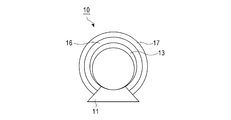
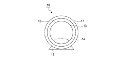
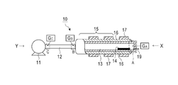
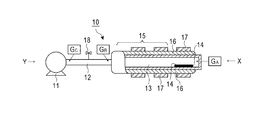
- FIG. 1 is a partially cutaway cross-sectional view schematically showing a cross section along the axial direction of a sublimation tube as viewed from above, with respect to one embodiment of the sublimation purification apparatus of the present invention. It is a schematic diagram when the sublimation refinement
- the Y-side vacuum tube is not shown. It is a figure which shows typically the measuring method of the conductance in the sublimation refinement
- the sublimation purification apparatus of the present invention includes a sublimation pipe (13), a vacuum pump (11), and a pipe (12) connecting the sublimation pipe (13) and the vacuum pump (11). Is provided.
- the conductance from the sublimation pipe to the pipe is increased to a specific level.
- the sublimation purification apparatus shown in each drawing is a schematic diagram for facilitating the understanding of the present invention, and the size or relative size relationship of each member may be changed for convenience of explanation. The relationship is not shown as it is. Moreover, it is not limited to the external shape and shape shown by these drawings except the matter prescribed
- an embodiment in which the inner diameter of the pipe is wider than the inner diameter of the sublimation tube can be preferably used in the present invention.
- the material of the sublimation tube used in the present invention is not particularly limited as long as it can withstand the high heat generated by the heat source during sublimation.
- the sublimation tube is usually heated to about 200 to 600 ° C. Therefore, generally, a sublimation tube made of glass, quartz, metal or the like is used. Of these, it is preferable to use a quartz sublimation tube.
- the shape of the sublimation tube used in the present invention is not particularly limited, and a commonly used shape can be adopted. However, since the inside becomes a high vacuum, the shape of the sublimation tube should be cylindrical from the viewpoint of applying pressure evenly. preferable.
- the term “cylindrical” is used to mean that a cross section perpendicular to the axial direction (hereinafter simply referred to as “cross section”) is circular or elliptical.
- Area of sublimation tube cross-section of the tube is preferably 3 ⁇ 800 cm 2, more preferably 30 ⁇ 500 cm 2, further preferably 100 ⁇ 400 cm 2.
- it satisfies 0.5 to 5, more preferably 0.8 to 3.
- the sublimation tube (13) used in the present invention usually has a terminal portion (also referred to as an X-side terminal portion) on the side away from the vacuum pump (11) or the vicinity thereof.
- the sublimation part (14) which arrange
- the collection part (15) in FIG. 1 shows the area
- the sublimation part is preferably present in a section located at the X-side end or in a section adjacent to this section when the sublimation tube is equally divided into 10 sections along the axial direction and divided into 10 sections.
- the X-side end of the sublimation tube is preferably closed, and the Y-side end is opened and connected to the pipe (12).
- the sublimation tube used in the present invention may have an inner tube disposed therein.
- the purified sublimation product can be collected on the inner wall of the inner tube, so that the purified sublimation product can be easily collected.
- the material of the piping used in the present invention there is no particular limitation on the material of the piping used in the present invention.
- metal, rubber, resin, or glass can be used. It is preferably made of metal from the viewpoint of use in a high vacuum and ease of processing.
- the metal material include stainless steel, aluminum, iron, copper, silver, gold, and metal alloys.
- the shape of the pipe used in the present invention is not particularly limited, and can be appropriately selected according to the shape of the sublimation tube.
- a cross section orthogonal to the fluid flow direction (hereinafter simply referred to as “cross section”). ) Is a circular hose-like pipe.
- the length of the pipe used in the present invention is appropriately determined depending on the arrangement of the sublimation pipe and the vacuum pump, but is preferably as short as possible. Specifically, it is preferably 200 cm or less, and more preferably 30 to 150 cm.
- [pipe length (cm) / axial length of sublimation tube (cm)] is preferably 0.1 to 3, more preferably 0.3 to 2, more preferably 0.5 It is more preferable to satisfy ⁇ 1.5.
- the piping used in the present invention preferably has a shape with as few curved portions as possible and more straight portions.
- the number of curved portions is preferably 0-6, more preferably 1-5, and even more preferably 2-4.
- the pipe used in the present invention is preferably subjected to a treatment for smoothing the inner surface of the pipe from the viewpoint of reducing the amount of gas released from the pipe surface.
- the smoothing method include electrolytic polishing, chemical polishing, and buffing. What was electropolished is preferable. It is also preferable to perform a process after assembling the apparatus, such as a baking process in which the piping is heated while being evacuated.
- the heating mode of the sublimation purification apparatus of the present invention is shown in “Experimental Chemistry Course (continued) 2 Separation and Purification” (Edited by Chemical Society of Japan, Publisher: Maruzen Co., Ltd., January 25, 1967), page 75. ⁇
- the nichrome wire may be wound directly around the sublimation tube, or the sublimation tube is installed in a metal tube with good thermal conductivity as shown in Figs.
- a form in which a heat source is installed and heated may be used. Since the temperature gradient can be changed smoothly, a type in which a sublimation tube is installed in a metal tube is preferable.
- a metal tube For example, stainless steel, aluminum, iron, copper, silver, gold
- a heat source for heating from the outside of the metal tube an arbitrary one such as an electric heater can be used.
- the number and arrangement of the heat sources can be arbitrarily set according to the physical properties of the sample to be purified and the required degree of purification.
- the number of heat sources is preferably 2 or more and 10 or less, more preferably 3 or more and 8 or less, and further preferably 4 or more and 6 or less along the axial direction of the sublimation tube. These heat sources are preferably those that can be independently temperature controlled. Moreover, it can also heat by the electromagnetic induction heating of patent 4866527.
- the sublimation tube is installed in the metal tube (16), and three heat sources (17) are arranged along the axial direction of the sublimation tube so as to surround the outside of the metal tube (16).
- the form is shown.
- the heat source is usually set to a gradually lower temperature from the X side to the Y side.
- the vacuum pump used in the present invention is not particularly limited, and a vacuum pump usually used in sublimation purification can be employed.
- the sublimation purification apparatus of this invention shows the specific conductance mentioned later.
- conductance corresponds to the reciprocal of the flow resistance, and is an index representing the ease of fluid flow.
- Conductance can be measured by a conventional method. For example, in order to calculate the conductance between any two points in the pipe, install a pressure gauge at each position, depressurize the pipe using a vacuum pump, and then move away from the vacuum pump of the sublimation pipe.
- FIG. 5 schematically shows a sublimation purification apparatus for measuring conductance in the sublimation purification apparatus of the present invention.
- a vacuum pump is operated to depressurize the inside of the pipe line to a predetermined level described later, and then a certain amount of argon gas is introduced from the X-side end of the sublimation pipe through the inlet (19) as shown in FIG. , where the value indicated by the pressure gauge G a and G C stable, measure the pressure of the pressure gauge G a ⁇ G C.
- K BC p B q / (p B ⁇ p C ) (2) q: Argon gas introduction flow rate (m 3 / sec) p B: the value of the pressure gauge G B (Pa) p C: the value of the pressure gauge G C (Pa)
- the conductance measurements in the present invention after which the vacuum pump is activated for all the pressure of the pressure gauge G A ⁇ G C stable with the following values 1 ⁇ 10 -2 Pa, (not operate the heat source) at room temperature Argon gas is introduced.
- the values of p A , p B , and p C are in the range of 1 ⁇ 10 ⁇ 4 to 1 ⁇ 10 0 Pa (1 Pa), and the flow rate q of argon gas is 1 ⁇ 10 ⁇ 10. Within the range of ⁇ 1 ⁇ 10 ⁇ 7 m 3 / sec. If the pressure (p A , p B , p C ) and the flow rate q are within the above ranges, K AC and K BC show almost constant values.
- the argon gas introduction flow rate was set to be constant within the range of 1 ⁇ 10 ⁇ 10 to 1 ⁇ 10 ⁇ 7 m 3 / sec, and after all values of the pressure gauges G A to G C were stabilized, Record the pressure gauge value. Further, the measurement is performed in the same procedure by changing the argon gas introduction flow rate within the range of 1 ⁇ 10 ⁇ 10 to 1 ⁇ 10 ⁇ 7 m 3 / sec. This is repeated 3 to 10 times, the conductance of each time is calculated, and the average value of the conductance of each time is defined as the conductance in the present invention.
- each pressure gauge can be installed by making a hole having a diameter of about 1 cm in a pipe or a sublimation pipe, attaching a pressure sensor, and then sealing. If a T-shaped vacuum pipe is used, it is easy to install a pressure gauge on the pipe.
- Argon gas can be introduced using a mass flow meter by opening a hole having a diameter of about 1 cm at the X-side end of the sublimation tube. If a gas inlet as shown in FIG. 5 is installed in advance at the X-side end of the sublimation tube, it is easy to introduce argon gas in a sealed state.
- Whether a certain sublimation purification apparatus is the sublimation purification apparatus of the present invention is determined by installing a pressure gauge as described above, providing an argon gas inlet, introducing argon gas, and calculating conductance from the value of each pressure gauge. It can be examined by measuring.
- the “terminal portion of the sublimation tube” indicates the inside of the compartment located on the most end side when the sublimation tube is divided into 10 sections along the axial direction.
- the “connection portion between the pipe and the vacuum pump” means that the pipe is in contact with the vacuum pump when the pipe is divided into 10 sections along the fluid flow direction (evacuation direction). It is assumed that the inside of the piping side section (ie, closest to the vacuum pump) is shown.
- connection portion between the sublimation pipe and the pipe means that the pipe is divided into 10 parts along the fluid flow direction (evacuation direction) and is divided into 10 sections, and is in contact with the sublimation pipe. (I.e., closest to the sublimation tube) inside the compartment on the piping side.
- the overlapping part for connecting the pipe and the vacuum pump or the overlapping part for connecting the pipe and the sublimation pipe is not included in the “pipe” which is divided into 10 equal parts in the description of each connection part.
- the “pipe” divided into 10 equal parts in the above description is a part of the pipe member of the sublimation purification apparatus excluding the overlapping part with the vacuum pump or the sublimation pipe.
- the K AC is 0.01 m 3 / sec or more.
- K AC is preferably 0.015 m 3 / sec or more, more preferably 0.02 m 3 / sec or more.
- K BC is 0.02 m 3 / sec or more.
- K BC is preferably 0.022 m 3 / sec or more, more preferably 0.03 m 3 / sec or more. Moreover, it is 0.5 m ⁇ 3 > / sec or less normally.
- the sublimation purification apparatus of the present invention may be provided with a control valve (18) in the middle of the piping as shown in FIG.
- the conductance can also be adjusted by changing the degree of opening and closing of the control valve (18).
- the conductance can also be adjusted by installing an obstacle (for example, a cylinder having an outer diameter smaller than the inner diameter of the sublimation tube) in the sublimation tube.
- the form of the sublimation purification apparatus of the present invention is not particularly limited, but is usually a horizontal type.
- the sublimation purification apparatus of the present invention may be in the form of sublimation while flowing gas under reduced pressure described in JP-A-2008-12479, or in the form of purification by a continuous method described in JP-T-2012-515643.
- a sublimation purification apparatus in which one end of a sublimation tube is closed as shown in FIGS.
- sublimation purification can be performed with the highest degree of vacuum in the capacity of the apparatus, and the sublimation temperature is less likely to increase due to a decrease in the degree of vacuum. That is, since thermal decomposition of the sublimation purification target sample accompanying an increase in sublimation temperature can be suppressed, it is particularly effective when a thermally unstable sample is used as a sublimation purification target.
- the sublimation purification apparatus of the present invention is useful even when the sublimation purification target sample is unstable to heat.
- the stability of the sample to be sublimated and purified with respect to heat includes not only the stability of the substance itself but also the effect of a decrease in stability due to the inclusion of an arbitrary impurity.
- the mass reduction rate by thermal mass spectrometry can be used as a guide. That is, it can be said that a sample having a large mass reduction rate when kept at a specific temperature for a certain time under normal pressure in an inert gas (for example, nitrogen, argon, etc.) sample is easily pyrolyzed.
- an inert gas for example, nitrogen, argon, etc.
- the specific temperature at the time of measurement of the mass reduction rate is the temperature of the sublimation part (sublimation temperature) at the time of sublimation purification. Therefore, the temperature at the time of measuring the mass reduction rate varies depending on the sample to be sublimated and purified.
- the mass reduction rate when kept at the sublimation temperature for 5 hours is taken as a measure of the stability to heat.
- mass reduction rate by thermal mass spectrometry (unit:%, calculation formula: 100 ⁇ ⁇ [before heating, when kept at sublimation temperature for 5 hours under normal pressure in an inert gas atmosphere) Mass] ⁇ [Mass after maintaining at sublimation temperature for 5 hours] ⁇ / [Mass before heating]) 2% or more can achieve high sublimation purification efficiency even if the sample is subjected to sublimation purification. Even if the sample is 5% or more, 10% or more, or 15% or more, high sublimation purification efficiency can be achieved.
- the mass reduction rate of the sublimation purification target sample is usually 40% or less, preferably 30% or less.
- the sublimation purification target sample (meaning the purification target product in the sublimation purification target sample here) is a compound represented by the following formula (I).
- D represents a donor group having a hetero atom.
- A represents an acceptor group having a carbonyl group or a cyano group.
- L 2 and L 3 represent a methine group. This methine group may have a substituent.
- the compound represented by the formula (I) is a donor-acceptor type dye compound, and when melted, the donor group D is easily decomposed due to a nucleophilic attack on the acceptor group A. That is, it is a compound having a melting point and a material decomposition temperature close to each other.
- Examples of the hetero atom that D has include a nitrogen atom, an oxygen atom, and a sulfur atom.
- the above D preferably has at least one nitrogen atom as a hetero atom.
- the compound represented by the above formula (I) is preferably a compound represented by the following formula (II).
- Z 1 represents a ring containing at least two carbon atoms and a 5-membered ring, a 6-membered ring, or a condensed ring containing at least one of a 5-membered ring and a 6-membered ring.
- L 1 represents a methine group. This methine group may have a substituent.
- L 2 , L 3 , D 1 and n have the same meanings as L 2 , L 3 , D and n in formula (I), respectively.
- Z 1 preferably has a ring structure which is usually used as an acidic nucleus in a merocyanine dye, and specific examples of this ring structure include the following (a) to (q).
- (A) 1,3-dicarbonyl nucleus for example, 1,3-indandione, 1,3-cyclohexanedione, 5,5-dimethyl-1,3-cyclohexanedione, or 1,3-dioxane-4,6- Zeon.
- (B) pyrazolinone nucleus for example 1-phenyl-2-pyrazolin-5-one, 3-methyl-1-phenyl-2-pyrazolin-5-one, or 1- (2-benzothiazoyl) -3-methyl- 2-pyrazolin-5-one.
- (C) isoxazolinone nucleus for example 3-phenyl-2-isoxazolin-5-one or 3-methyl-2-isoxazolin-5-one.
- this derivative examples include 1-alkyl compounds such as 1-methyl and 1-ethyl; 1,3-dialkyl compounds such as 1,3-dimethyl, 1,3-diethyl and 1,3-dibutyl; 1,3-diphenyl 1,3-diaryl compounds such as 1,3-di (p-chlorophenyl) and 1,3-di (p-ethoxycarbonylphenyl); 1-alkyl-1-aryl compounds such as 1-ethyl-3-phenyl And 1,3-diheterocyclic substituents such as 1,3-di (2-pyridyl).
- 2-thio-2,4-thiazolidinedione nucleus for example, rhodanine and its derivatives.
- this derivative examples include 3-alkylrhodanine such as 3-methylrhodanine, 3-ethylrhodanine and 3-allylrhodanine; 3-arylrhodanine such as 3-phenylrhodanine; and 3- (2-pyridyl). ) 3-position heterocyclic substituted rhodanine such as rhodanine.
- (J) 2,4-thiazolidinedione nucleus for example, 2,4-thiazolidinedione, 3-ethyl-2,4-thiazolidinedione, or 3-phenyl-2,4-thiazolidinedione.
- (K) Thiazolin-4-one nucleus for example 4-thiazolinone or 2-ethyl-4-thiazolinone.
- (M) 2-thio-2,4-imidazolidinedione (2-thiohydantoin) nucleus for example 2-thio-2,4-imidazolidinedione, or 3-ethyl-2-thio-2,4-imidazolidine Zeon etc.
- Benzothiophen-3-one nucleus for example, benzothiophen-3-one, oxobenzothiophen-3-one, or dioxobenzothiophen-3-one.
- Indanone nucleus for example, 1-indanone, 3-phenyl-1-indanone, 3-methyl-1-indanone, 3,3-diphenyl-1-indanone, or 3,3-dimethyl-1-indanone.
- the ring structure represented by Z 1 is preferably a 1,3-dicarbonyl nucleus, a pyrazolinone nucleus, a 2,4,6-triketohexahydropyrimidine nucleus (including a thioketone body, such as barbituric acid, 2-thiobarbiti Tool acid, the same shall apply hereinafter), 2-thio-2,4-thiazolidinedione nucleus, 2-thio-2,4-oxazolidinedione nucleus, 2-thio-2,5-thiazolidinedione nucleus, 2,4-thiazolidinedione Nucleus, 2,4-imidazolidinedione nucleus, 2-thio-2,4-imidazolidinedione nucleus, 2-imidazolin-5-one nucleus, 3,5-pyrazolidinedione nucleus, benzothiophen-3-one nucleus Or a structure of an indanone nucleus, more preferably a 1,3-
- L 1 , L 2 , and L 3 of formula (II) when the methine group has a substituent, the substituents may be bonded to each other to form a ring (eg, a 6-membered ring such as a benzene ring). Examples of the substituent that the methine group may have include the substituent W described later.
- L 1 , L 2 and L 3 are preferably all unsubstituted methine groups.
- n preferably represents an integer of 0 or more and 3 or less, more preferably 0.
- n is increased, the thermal decomposition temperature is lowered.
- D 1 is preferably a group having —NR a (R b ). More preferably, D 1 is an aryl group having —NR a (R b ) as a substituent (preferably a phenyl group or naphthyl group having —NR a (R b ) as a substituent).
- R a and R b each independently represent a hydrogen atom or a substituent, and examples of the substituent represented by R a or R b include the substituent W described later.
- an alkyl group, an aryl group, An alkoxy group, an aryloxy group, a silyl group, or an aromatic heterocyclic group preferably a 5-membered ring, specifically, furan, thiophene, pyrrole, or oxadiazole
- D 1 is preferably an aryl group (preferably a phenyl group) substituted with an amino group (—NR a (R b )) at the para position.
- D 1 is preferably represented by the following formula (II-1).
- R 1 to R 6 each independently represents a hydrogen atom or a substituent. As this substituent, the substituent W mentioned later is mentioned. R 1 and R 2 , R 3 and R 4 , R 5 and R 6 , R 2 and R 5 , and R 4 and R 6 may be bonded to each other to form a ring. Examples of the ring to be formed include ring RI described later. * In the formula (II-1) represents a linking site with L 3 (L 1 when n is 0). R 1 to R 4 are preferably all hydrogen atoms, or R 2 and R 5 or R 4 and R 6 are preferably linked to form a 5-membered ring, more preferably R 1 to R 4. All 4 are hydrogen atoms.
- R 5 and R 6 are preferably an aryl group, and the aryl group may have a substituent.
- the substituent that the aryl group may have, an alkyl group (for example, methyl group, ethyl group) or an aryl group (for example, phenyl group, naphthylene group, phenanthryl group, anthryl group) is preferable.
- R 5 and R 6 are preferably a phenyl group, an alkyl-substituted phenyl group, a phenyl-substituted phenyl group, a naphthyl group, a phenanthryl group, an anthryl group or a fluorenyl group (preferably a 9,9′-dimethyl-2-fluorenyl group).
- D 1 is preferably represented by the following formula (II-2).
- R 811 to R 814 , R 820 to R 824 , and R 830 to R 834 each independently represents a hydrogen atom or a substituent.
- the substituent include a substituent W described later, preferably an alkyl group (for example, a methyl group or an ethyl group) or an aryl group (for example, a phenyl group or a naphthyl group). It may have a substituent W (preferably an aryl group).
- R 820 and R 830 are preferably substituents, and the other R 811 to R 814 , R 821 to R 824 , and R 831 to R 834 are more preferably hydrogen atoms.
- R 811 to R 814 , R 820 to R 824 , and R 830 to R 834 may be bonded to each other to form a ring.
- the ring to be formed include ring RI described later.
- R 811 and R 812 , R 813 and R 814 are bonded to form a benzene ring
- two adjacent R 820 to R 824 R 824 and R 823 , R 823 and R 820 , R 820 and R 821 , R 821 and R 822
- R 830 to R 834 R 834 and R 833 , R 833 and R 830 , R 830 and R 831 , R 831 and R 832
- R 822 and R 834 , R 812 and R 824 , R 814 and R 832 are combined to form a 5-member
- the compound represented by the formula (I) or (II) can be produced according to the synthesis method described in JP-A No. 2000-297068. Specific examples of the compound represented by formula (I) or (II) are shown below, but the present invention is not limited thereto.
- the substituent W is listed below.
- An alkyl group preferably having 1 to 20 carbon atoms, such as methyl, ethyl, isopropyl, t-butyl, pentyl, heptyl, 1-ethylpentyl, benzyl, 2-ethoxyethyl, 1-carboxymethyl, trifluoromethyl, etc.
- Alkenyl groups preferably having 2 to 20 carbon atoms, such as vinyl, allyl, oleyl, etc.
- alkynyl groups preferably having 2 to 20 carbon atoms, such as ethynyl, butadiynyl, phenylethynyl, etc.
- cycloalkyl groups preferably Has 3 to 20 carbon atoms, for example, cyclopropyl, cyclopentyl, cyclohexyl, 4-methylcyclohexyl, etc.
- cycloalkenyl group preferably having 5 to
- alkoxycarbonyl group preferably having 2 to 20 carbon atoms such as ethoxycarbonyl, 2-ethylhexyloxycarbonyl, etc.
- a cycloalkoxycarbonyl group preferably having 4 to 20 carbon atoms such as cyclopropyloxycarbonyl, cyclopentyloxycarbonyl, etc.
- Cyclohexyloxycarbonyl, etc. aryloxycarbonyl groups (preferably having 6 to 20 carbon atoms, such as phenyloxycarbonyl, naphthyloxycarbonyl, etc.)
- amino groups preferably having 0 to 20 carbon atoms, alkylamino groups, alkenyls
- An acyl group (preferably having 1 to 20 carbon atoms such as acetyl, cyclohexylcarbonyl, benzoyl, etc.), an acyloxy group (preferably having 1 to 20 carbon atoms such as acetyloxy, cyclohexylcarbonyl, etc.) Xy, benzoyloxy, etc.), carbamoyl groups (preferably having 1 to 20 carbon atoms, alkyl, cycloalkyl or aryl carbamoyl groups are preferred, such as N, N-dimethylcarbamoyl, N-cyclohexylcarbamoyl, N-phenylcarbamoyl, etc. ),
- An acylamino group (preferably an acylamino group having 1 to 20 carbon atoms, such as acetylamino, cyclohexylcarbonylamino, benzoylamino, etc.), a sulfonamide group (preferably an alkyl, cycloalkyl or aryl sulfonamide having 0 to 20 carbon atoms) Groups such as methanesulfonamide, benzenesulfonamide, N-methylmethanesulfonamide, N-cyclohexylsulfonamide, N-ethylbenzenesulfonamide, etc., alkylthio groups (preferably having 1 to 20 carbon atoms, for example, Methylthio, ethylthio, isopropylthio, benzylthio, etc.), cycloalkylthio groups (preferably having 3 to 20 carbon atoms, such as cyclopropylthio, cyclopen
- a silyl group (preferably a silyl group having 1 to 20 carbon atoms and substituted by alkyl, aryl, alkoxy and aryloxy, such as triethylsilyl, triphenylsilyl, diethylbenzylsilyl, dimethylphenylsilyl, etc.), silyloxy group ( Preferably, it is a silyloxy group having 1 to 20 carbon atoms and substituted with alkyl, aryl, alkoxy and aryloxy, such as triethylsilyloxy, triphenylsilyloxy, diethylbenzylsilyloxy, dimethylphenylsilyloxy, etc.), hydroxyl group , Cyano group, nitro group, halogen atom (for example, fluorine atom, chlorine atom, bromine atom, iodine atom), carboxyl group, sulfo group, phosphonyl group, phosphoryl group, boric acid group.
- a compound or a substituent when a compound or a substituent includes an alkyl group, an alkenyl group, etc., these may be linear or branched, and may be substituted or unsubstituted. When an aryl group, a heterocyclic group, or the like is included, they may be monocyclic or condensed, and may be substituted or unsubstituted.
- substituent W when each group is only described (for example, described as “alkyl group”) The only preferred ranges in the corresponding groups of this substituent W, specific examples apply.
- Ring RI examples include an aromatic or non-aromatic hydrocarbon ring, a heterocyclic ring, and a polycyclic condensed ring formed by further combining these.
- the control valve (18) was provided in piping.
- the sublimation tube was a cylindrical quartz glass tube, the cross-sectional area of the tube was 78.5 cm 2 , and the axial length was 100 cm.
- the said piping employ
- tube was 81 cm ⁇ 2 >, and length was 50 cm.
- TG201C manufactured by Ampere Co.
- argon gas was introduced at a flow rate of 3.3 ⁇ 10 ⁇ 9 m 3 / sec, 6.7 ⁇ 10 ⁇ 9 m 3 / sec, 1.0 ⁇ 10 ⁇ 8 m 3 / sec,
- the pressure gauges G A to G C were read at the respective flow rates set to 0.7 ⁇ 10 ⁇ 8 m 3 / sec and 3.3 ⁇ 10 ⁇ 8 m 3 / sec.
- the obtained values were applied to the above formulas (1) and (2) to determine the conductance K AC between AC and the conductance K BC between BC . Wherein each K AC and K BC were the average of the K AC and K BC in the five flow of the argon gas.
- the coarse body 100g was arrange
- the sublimation part (14) is 325 ° C. using a pipe heater (17) as a heat source.
- the sublimation purification was performed so that the temperature gradually decreased toward the Y side end of the sublimation tube (13) (temperature of the Y side end in the sublimation tube: 100 ° C.).
- the sublimation tube (13) is disposed in a brass metal tube (16), and a heat source (17) is disposed around the metal tube (16). did.
- the heating was stopped, the whole sublimation tube was cooled to room temperature, and then released to the atmosphere.
- the purified sublimation product and the sublimation residue were taken out, and the mass was measured. The results are shown in Table 1.
- the K AC sublimation refining apparatus is set to 0.010 3 / sec or more, it was found that the sublimation purification efficiency is greatly improved. Further, the K BC sublimation refining apparatus is set to 0.02 m 3 / sec or more, it was found that the sublimation purification efficiency is further improved.
- the coarse body 10g was arrange
- the pipe heater (17) is used as a heat source to set the sublimation part (14) in Table 2.
- Sublimation purification was performed by heating to the indicated temperature and gradually decreasing the temperature toward the Y side end of the sublimation tube (13) (temperature of the Y side end in the sublimation tube: 100 ° C.).
- the sublimation tube (13) is disposed in a brass metal tube (16), and a heat source (17) is disposed around the metal tube (16). did.
- the heating was stopped, the whole sublimation tube was cooled to room temperature, and then released to the atmosphere.
- the purified sublimation product and the sublimation residue were taken out, and the mass was measured. The results are shown in Table 2.
- Test Example 3 For compounds A to E, the mass reduction rate was measured using a thermogravimetric apparatus when the compound was maintained at the sublimation temperature of each compound described in Test Example 1 or 2 for 5 hours under a normal pressure nitrogen atmosphere. The results are shown in Table 3.
- Tables 1 and 2 show that the amount of purified sublimation and the amount of sublimation residue are compared between the comparative example not depending on the method of the present invention and the example based on the present invention. 14 to Comparative Examples 1 to 7, Example 15 and Comparative Example 8 for Compound B, Example 16 and Comparative Example 9 for Compound C, and Comparison of Example 17 and Comparative Example 10 for Compound D
- the amount of purified sublimation was significantly increased, and the amount of sublimation residue was significantly decreased. Since Compounds A to D are low thermal stability compounds (Table 3), by using the sublimation purification apparatus of the present invention, sublimation purification can be performed efficiently regardless of the thermal stability of the sublimation purification target sample. It has been shown.
Landscapes
- Chemical & Material Sciences (AREA)
- Organic Chemistry (AREA)
- Chemical Kinetics & Catalysis (AREA)
- Vaporization, Distillation, Condensation, Sublimation, And Cold Traps (AREA)
Abstract
昇華管と、真空ポンプと、該昇華管と該真空ポンプとを繋ぐ配管とを有する昇華精製装置であって、 前記昇華管の、前記真空ポンプから離れた側の末端部をAとし、前記配管と前記真空ポンプとの接続部をCとしたとき、AからCまでのコンダクタンス(KAC)が0.01m3/秒以上である昇華精製装置、及びこれを用いた昇華精製方法。
Description
本発明は、昇華精製装置及び昇華精製方法に関する。
昇華精製装置は、常温で固体状態の物質が適当な温度と圧力の下で気化する特性を利用して目的物質を精製するための装置であり、化学物質を高純度に精製するために用いられている。例えば、有機エレクトロルミネッセンス材料を用いた発光デバイスでは、有機エレクトロルミネッセンス材料中に微量の不純物が含まれるだけでも、発光デバイスの性能が大きく低下する。したがって、材料をより高度に精製するために昇華精製装置が用いられている。
昇華精製装置には、垂直型、水平型等の種々の形態が存在する。昇華精製装置は通常、精製対象物が設置される昇華部と昇華精製物を捕集する捕集部とを備えた昇華管と、真空ポンプと、昇華管と真空ポンプとを繋ぐ配管とを備え、さらに昇華部を加熱するための熱源が配設される。熱源によって昇華部が加熱されると試料が昇華し、気化物は真空ポンプ側に流れながら冷やされ、一定温度以下になると固化する。目的物を捕集部で固化・捕集するために、精製対象物の種類に応じて、昇華管の軸方向に沿って適宜に温度勾配が設けられる。
昇華精製では、精製目的物を含む昇華精製対象物(以下、「昇華粗体」又は単に「粗体」ともいう。)の昇華効率を向上させることで精製物の収率が向上する。しかし、通常は粗体の一部が昇華せずに少なからず残存してしまう。この残存率は粗体の熱安定性が低い場合により高まる傾向にある。
本発明は、熱安定性の高い粗体のみならず、熱安定性の低い粗体を試料とした場合においても、昇華効率をより向上させることができる昇華精製装置、及びこれを用いた昇華精製方法の提供を課題とする。
本発明は、熱安定性の高い粗体のみならず、熱安定性の低い粗体を試料とした場合においても、昇華効率をより向上させることができる昇華精製装置、及びこれを用いた昇華精製方法の提供を課題とする。
本発明者らは、目的物の昇華に適した温度や減圧条件を採用しても、粗体から発生する種々の気体(例えば、粗体に含まれる揮発性不純物や、粗体の熱分解によって生じる気体等)によって昇華管内の真空度が想定よりも低下してしまう現象に着目した。そして、この真空度の低下が粗体の昇華効率を悪化させるとともに粗体の分解をも亢進し、さらに昇華効率を低下させるという悪循環を引き起こしているとの考えに至った。
本発明者らは、上記の真空度の低下を抑制すべく鋭意検討を重ねた。その結果、昇華管から配管にかけてのコンダクタンスを特定のレベルにまで高めた昇華精製装置を用いると、昇華精製時における昇華管内の真空度の過度の低下が抑制され、これにより、昇華残留物が低減され、昇華精製をより高い収率で行えることを見い出した。
本発明はこれらの知見に基づきさらに検討を重ね、完成されるに至ったものである。
本発明者らは、上記の真空度の低下を抑制すべく鋭意検討を重ねた。その結果、昇華管から配管にかけてのコンダクタンスを特定のレベルにまで高めた昇華精製装置を用いると、昇華精製時における昇華管内の真空度の過度の低下が抑制され、これにより、昇華残留物が低減され、昇華精製をより高い収率で行えることを見い出した。
本発明はこれらの知見に基づきさらに検討を重ね、完成されるに至ったものである。
上記の課題は以下の手段により達成された。
<1>昇華管と、真空ポンプと、昇華管と真空ポンプとを繋ぐ配管とを有する昇華精製装置であって、
上記昇華管の、上記真空ポンプから離れた側の末端部をAとし、上記配管と上記真空ポンプとの接続部をCとしたとき、AからCまでのコンダクタンスKACが0.01m3/秒以上である、昇華精製装置。
<2>上記昇華管と上記配管との接続部をBとしたとき、BからCまでのコンダクタンスKBCが0.02m3/秒以上である、上記<1>に記載の昇華精製装置。
<3>上記KACが0.02m3/秒以上である、上記<1>又は<2>に記載の昇華精製装置。
<4>上記KBCが0.03m3/秒以上である、上記<1>~<3>のいずれかに記載の昇華精製装置。
<5>上記昇華管の真空ポンプから離れた側の末端部が閉じている、上記<1>~<4>のいずれかに記載の昇華精製装置。
<6>上記<1>~<5>のいずれかに記載の昇華精製装置を用いた昇華精製方法であって、不活性ガス雰囲気中、常圧下、昇華温度に5時間保ったときの質量減少率が2%以上である試料を昇華精製対象試料とする、昇華精製方法。
<7>上記昇華精製対象試料が、不活性ガス雰囲気中、常圧下、昇華温度に5時間保ったときの質量減少率が10%以上である、<6>に記載の昇華精製方法。
<1>昇華管と、真空ポンプと、昇華管と真空ポンプとを繋ぐ配管とを有する昇華精製装置であって、
上記昇華管の、上記真空ポンプから離れた側の末端部をAとし、上記配管と上記真空ポンプとの接続部をCとしたとき、AからCまでのコンダクタンスKACが0.01m3/秒以上である、昇華精製装置。
<2>上記昇華管と上記配管との接続部をBとしたとき、BからCまでのコンダクタンスKBCが0.02m3/秒以上である、上記<1>に記載の昇華精製装置。
<3>上記KACが0.02m3/秒以上である、上記<1>又は<2>に記載の昇華精製装置。
<4>上記KBCが0.03m3/秒以上である、上記<1>~<3>のいずれかに記載の昇華精製装置。
<5>上記昇華管の真空ポンプから離れた側の末端部が閉じている、上記<1>~<4>のいずれかに記載の昇華精製装置。
<6>上記<1>~<5>のいずれかに記載の昇華精製装置を用いた昇華精製方法であって、不活性ガス雰囲気中、常圧下、昇華温度に5時間保ったときの質量減少率が2%以上である試料を昇華精製対象試料とする、昇華精製方法。
<7>上記昇華精製対象試料が、不活性ガス雰囲気中、常圧下、昇華温度に5時間保ったときの質量減少率が10%以上である、<6>に記載の昇華精製方法。
本発明の昇華精製装置は、これを用いて昇華精製を行うことで、昇華精製物の収率をより高めることができる。
本発明の上記及び他の特徴及び利点は、適宜添付の図面を参照して、下記の記載からより明らかになるであろう。
以下、本発明について詳細に説明する。
本発明の昇華精製装置は、図1~4に示すように、昇華管(13)と、真空ポンプ(11)と、昇華管(13)と真空ポンプ(11)とを繋ぐ配管(12)とを備える。本発明の昇華精製装置は、昇華管から配管にかけてのコンダクタンスが特定のレベルにまで高められている。各図面に示される昇華精製装置は、本発明の理解を容易にするための模式図であり、各部材のサイズないし相対的な大小関係等は説明の便宜上大小を変えている場合があり、実際の関係をそのまま示すものではない。また、本発明で規定する事項以外はこれらの図面に示された外形、形状に限定されるものでもない。例えば、配管の内径が昇華管の内径よりも広い態様も本発明に好ましく用いることができる。
本発明に用いる昇華管の材質は、昇華させる際に熱源が発する高熱に耐えるものであれば特に制限はない。昇華精製では、昇華管は通常、200~600℃程度にまで加熱される。したがって、一般的にはガラス製、石英製、金属製等の昇華管が用いられる。なかでも石英製の昇華管を用いることが好ましい。
本発明に用いる昇華管の形状も特に制限はなく、通常用いられる形状を採用することができるが、内部が高真空になるため、圧力が均等にかかるようにする観点から円筒形であることが好ましい。本明細書において「円筒形」とは、その軸線方向に対し直交する断面(以下、単に「断面」という。)が、円状である他、楕円状のものも包含する意味に用いる。昇華管断面の管内の面積(管内断面積)は、3~800cm2であることが好ましく、30~500cm2であることがより好ましく、100~400cm2であることがさらに好ましい。本発明の装置では、発生する気体による真空度低下にコンダクタンスが影響されやすい、管内断面積のより大きな昇華管を用いることが好ましい。
本発明に用いる昇華管は、軸線方向の長さと、管内断面積とが、[軸線方向の長さ(cm)]/[管内断面積(cm2)]=0.2~50を満たすことが好ましく、0.5~5を満たすことがより好ましく、0.8~3を満たすことがさらに好ましい。
図1~4に示されるように、本発明に用いる昇華管(13)内には、通常は真空ポンプ(11)から離れた側の末端部(X側末端部ともいう。)又はその近傍に粗体を配設する昇華部(14)が設けられ、昇華部(14)から、昇華管の配管側末端部(配管との接続部(Y側末端部ともいう。))までの間の全部又は一部を、昇華によって生じた蒸気を固体として析出させる捕集部(15)とする。なお、図1中の捕集部(15)は昇華管内の領域を示す。
昇華部は、昇華管を軸線方向に沿って10等分して10区画に分けたときに、X側末端に位置する区画内又は、この区画に隣接する区画内に存在することが好ましい。
上記昇華管のX側末端部は閉じていることが好ましく、Y側末端部は開口して配管(12)と接続される。
昇華部は、昇華管を軸線方向に沿って10等分して10区画に分けたときに、X側末端に位置する区画内又は、この区画に隣接する区画内に存在することが好ましい。
上記昇華管のX側末端部は閉じていることが好ましく、Y側末端部は開口して配管(12)と接続される。
本発明に用いる昇華管は、その内部に内管を配設してもよい。内管を設けることで、昇華精製物を内管の内壁に捕集することができるため、昇華精製物の回収が容易となる。
本発明に用いる配管の材質に特に制限はない。例えば、金属製、ゴム製、樹脂製、又はガラス製のものを使用することができる。高真空で使用することおよび加工の容易さの観点から金属製であることが好ましい。この金属の材質としては、例えば、ステンレス、アルミ、鉄、銅、銀、金、金属合金が挙げられる。
本発明に用いる配管の形状も特に制限はなく、昇華管の形状に合わせて適宜選択することができるが、通常には流体の流れる方向に対して直交する断面(以下、単に「断面」という。)が円形のホース状の配管が用いられる。
本発明に用いる配管の長さ(流体が流れる方向の長さ、以下同様)は、昇華管と真空ポンプの配置によって適宜決められるが、可能な限り短くすることが好ましい。具体的には、200cm以下であることが好ましく、30~150cmであることがより好ましい。
さらに、[配管の長さ(cm)/昇華管の軸方向の長さ(cm)]=0.1~3を満たすことが好ましく、0.3~2を満たすことがより好ましく、0.5~1.5を満たすことがさらに好ましい。
また、配管の管内断面積と昇華管の管内断面積との関係は、[配管の管内断面積(cm2)/昇華管の管内断面積(cm2)]=0.3~3を満たすことが好ましく、0.5~2を満たすことがより好ましく、0.8~1.5を満たすことがさらに好ましい。
本発明に用いる配管は、曲線部分が可能な限り少なく直線部分がより多い形状が好ましい。曲線部分の数は0~6箇所が好ましく、1~5箇所がより好ましく、2~4箇所がさらに好ましい。
本発明に用いる配管は、配管表面からの放出ガス量を減少させる観点から配管内側の表面を平滑化する処理が施されていることが好ましい。平滑化処理の方法としては、電解研磨、化学研磨、バフ研磨などが挙げられる。電解研磨したものが好ましい。配管を真空排気しながら加熱するベーキング処理などの装置組み立て後の処理をおこなうことも好ましい。
本発明に用いる配管の長さ(流体が流れる方向の長さ、以下同様)は、昇華管と真空ポンプの配置によって適宜決められるが、可能な限り短くすることが好ましい。具体的には、200cm以下であることが好ましく、30~150cmであることがより好ましい。
さらに、[配管の長さ(cm)/昇華管の軸方向の長さ(cm)]=0.1~3を満たすことが好ましく、0.3~2を満たすことがより好ましく、0.5~1.5を満たすことがさらに好ましい。
また、配管の管内断面積と昇華管の管内断面積との関係は、[配管の管内断面積(cm2)/昇華管の管内断面積(cm2)]=0.3~3を満たすことが好ましく、0.5~2を満たすことがより好ましく、0.8~1.5を満たすことがさらに好ましい。
本発明に用いる配管は、曲線部分が可能な限り少なく直線部分がより多い形状が好ましい。曲線部分の数は0~6箇所が好ましく、1~5箇所がより好ましく、2~4箇所がさらに好ましい。
本発明に用いる配管は、配管表面からの放出ガス量を減少させる観点から配管内側の表面を平滑化する処理が施されていることが好ましい。平滑化処理の方法としては、電解研磨、化学研磨、バフ研磨などが挙げられる。電解研磨したものが好ましい。配管を真空排気しながら加熱するベーキング処理などの装置組み立て後の処理をおこなうことも好ましい。
本発明の昇華精製装置の加熱の形態は、「実験化学講座(続)2 分離と精製」(日本化学会編、発行者:丸善株式会社、1967年1月25日)第75頁の図3・7のように、昇華管にニクロム線を直接巻き付ける形式でもよいし、図3・16のように昇華管を熱伝導性の良い金属管の中に設置し、金属管の外側を取り巻くように熱源を設置して加熱する形式であってもよい。温度勾配を滑らかに変化させられることから、金属管の中に昇華管を設置する形式が好ましい。金属管の材質に制限はなく、例えば、ステンレス、アルミ、鉄、銅、銀、金、金属合金が挙げられる。
金属管の外側から加熱する熱源としては、電熱ヒーターなど任意のものを用いることができる。熱源の個数および配置は、精製する試料の物性および要求される精製度に応じて任意に設定することができる。熱源の個数は、昇華管の軸線方向に沿って2個以上10個以下が好ましく、3個以上8個以下がより好ましく、4個以上6個以下がさらに好ましい。これらの熱源は独立して温度制御できるものが好ましい。また、特許第4866527号に記載の電磁誘導加熱によって加熱することもできる。
図1~6には、昇華管は金属管(16)の中に設置され、金属管(16)の外側を取り巻くように昇華管の軸線方向に沿って3つの熱源(17)が配設された形態が示されている。この場合、熱源は、通常にはX側からY側に向けて段階的に低い温度に設定される。
金属管の外側から加熱する熱源としては、電熱ヒーターなど任意のものを用いることができる。熱源の個数および配置は、精製する試料の物性および要求される精製度に応じて任意に設定することができる。熱源の個数は、昇華管の軸線方向に沿って2個以上10個以下が好ましく、3個以上8個以下がより好ましく、4個以上6個以下がさらに好ましい。これらの熱源は独立して温度制御できるものが好ましい。また、特許第4866527号に記載の電磁誘導加熱によって加熱することもできる。
図1~6には、昇華管は金属管(16)の中に設置され、金属管(16)の外側を取り巻くように昇華管の軸線方向に沿って3つの熱源(17)が配設された形態が示されている。この場合、熱源は、通常にはX側からY側に向けて段階的に低い温度に設定される。
本発明に用いる真空ポンプに特に制限はなく、昇華精製において通常用いられる真空ポンプを採用することができる。
本発明の昇華精製装置は、後述する特定のコンダクタンスを示す。本明細書において「コンダクタンス」とは、流動抵抗の逆数に相当し、流体の流れやすさを表す指標である。
コンダクタンスは常法により測定することができる。例えば、管路中における任意の2点間のコンダクタンスを算出するには、それぞれの位置に圧力計を設置し、管路内を真空ポンプを用いて減圧した後に、昇華管の、真空ポンプから離れた側の末端(X側末端)から微量の気体を流し、この微量の気体を流している状態における各圧力計の値から、「改訂五版 化学工学便覧」(社団法人化学工学協会編、発行所:丸善株式会社、1988年3月1日)、第5章、第311頁の(5・321)式を用いて算出することができる。コンダクタンスの測定方法を、以下に図面を用いてより詳細に説明する。
コンダクタンスは常法により測定することができる。例えば、管路中における任意の2点間のコンダクタンスを算出するには、それぞれの位置に圧力計を設置し、管路内を真空ポンプを用いて減圧した後に、昇華管の、真空ポンプから離れた側の末端(X側末端)から微量の気体を流し、この微量の気体を流している状態における各圧力計の値から、「改訂五版 化学工学便覧」(社団法人化学工学協会編、発行所:丸善株式会社、1988年3月1日)、第5章、第311頁の(5・321)式を用いて算出することができる。コンダクタンスの測定方法を、以下に図面を用いてより詳細に説明する。
図5には、本発明の昇華精製装置におけるコンダクタンスを測定するための昇華精製装置が模式的に示されている。昇華管(13)のX側末端部Aに圧力計GAを、配管(12)と昇華管(13)との接続部Bに圧力計GBを、配管(12)と真空ポンプ(11)との接続部Cに圧力計GCをそれぞれ設置する。
真空ポンプを作動させて管路内を後述の所定のレベルまで減圧してから、昇華管のX側末端部から図5に示されるような導入口(19)を通して一定量のアルゴンガスを導入し、圧力計GA及びGCが示す値が安定したところで、圧力計GA~GCの圧力を測定する。これらの作業はすべて室温下(通常10~30℃)で行われる(熱源を作動させないで行われる)。
なお、図5には昇華部が示されているが、コンダクタンスの測定時には昇華部に粗体は配置しない。
このとき、AからCまでのコンダクタンスKAC(m3/秒)は下記式(1)で求められる。
KAC=pAq/(pA-pC) ・・・式(1)
q:アルゴンガスの導入流量(m3/秒)
pA:圧力計GAの値(Pa)
pC:圧力計GCの値(Pa)
真空ポンプを作動させて管路内を後述の所定のレベルまで減圧してから、昇華管のX側末端部から図5に示されるような導入口(19)を通して一定量のアルゴンガスを導入し、圧力計GA及びGCが示す値が安定したところで、圧力計GA~GCの圧力を測定する。これらの作業はすべて室温下(通常10~30℃)で行われる(熱源を作動させないで行われる)。
なお、図5には昇華部が示されているが、コンダクタンスの測定時には昇華部に粗体は配置しない。
このとき、AからCまでのコンダクタンスKAC(m3/秒)は下記式(1)で求められる。
KAC=pAq/(pA-pC) ・・・式(1)
q:アルゴンガスの導入流量(m3/秒)
pA:圧力計GAの値(Pa)
pC:圧力計GCの値(Pa)
また、上記BからCまでのコンダクタンスKBC(m3/秒)は下記式(2)で求められる。
KBC=pBq/(pB-pC) ・・・式(2)
q:アルゴンガスの導入流量(m3/秒)
pB:圧力計GBの値(Pa)
pC:圧力計GCの値(Pa)
KBC=pBq/(pB-pC) ・・・式(2)
q:アルゴンガスの導入流量(m3/秒)
pB:圧力計GBの値(Pa)
pC:圧力計GCの値(Pa)
本発明におけるコンダクタンスの測定では、真空ポンプを作動させて圧力計GA~GCのすべての圧力が1×10⁻²Pa以下の値で安定した後、室温下で(熱源を作動させないで)アルゴンガスを導入する。また、コンダクタンスの測定に当たり、pA、pB、pCの値は1×10⁻⁴~1×100Pa(1Pa)の範囲内とし、アルゴンガスの導入流量qは、1×10⁻¹⁰~1×10⁻⁷m3/秒の範囲内とする。圧力(pA、pB、pC)と流量qが上記の範囲内であれば、KAC及びKBCはほぼ一定の値を示す。
アルゴンガス導入流量が1×10⁻¹⁰~1×10⁻⁷m3/秒の範囲内で一定になるように設定し、圧力計GA~GCのすべての値が安定してから、それぞれの圧力計の値を記録する。さらに、アルゴンガス導入流量を1×10-10~1×10-7m3/秒の範囲内で変えて同様の手順で測定を行う。これを3~10回繰り返し、各回のコンダクタンスを算出し、各回のコンダクタンスの平均値を本発明におけるコンダクタンスとする。
アルゴンガス導入流量が1×10⁻¹⁰~1×10⁻⁷m3/秒の範囲内で一定になるように設定し、圧力計GA~GCのすべての値が安定してから、それぞれの圧力計の値を記録する。さらに、アルゴンガス導入流量を1×10-10~1×10-7m3/秒の範囲内で変えて同様の手順で測定を行う。これを3~10回繰り返し、各回のコンダクタンスを算出し、各回のコンダクタンスの平均値を本発明におけるコンダクタンスとする。
本発明におけるコンダクタンスの測定では、各圧力計の設置は、配管や昇華管に直径1cm程度の穴を開け、圧力センサーを取り付けた後、密閉することで行うことができる。T字型の真空配管を使用すれば、配管への圧力計の設置が容易である。
また、アルゴンガスの導入は、昇華管のX側末端部に直径1cm程度の穴を開け、マスフローメーターを用いて行うことができる。昇華管のX側末端部に、あらかじめ、図5に示すようなガス導入口を設置しておけば、密閉状態でのアルゴンガスの導入が容易である。
ある昇華精製装置が本発明の昇華精製装置であるか否かは、上記のように圧力計を設置し、アルゴンガスの導入口を設けてアルゴンガスを導入し、各圧力計の値からコンダクタンスを測定することで調べることができる。
また、アルゴンガスの導入は、昇華管のX側末端部に直径1cm程度の穴を開け、マスフローメーターを用いて行うことができる。昇華管のX側末端部に、あらかじめ、図5に示すようなガス導入口を設置しておけば、密閉状態でのアルゴンガスの導入が容易である。
ある昇華精製装置が本発明の昇華精製装置であるか否かは、上記のように圧力計を設置し、アルゴンガスの導入口を設けてアルゴンガスを導入し、各圧力計の値からコンダクタンスを測定することで調べることができる。
本発明において、「昇華管の末端部」とは、昇華管を軸線方向に沿って10等分して10区画に分けたときに、最末端側に位置する区画内を示すものとする。なお、昇華管のX側末端部(閉じた末端部)がドーム状の丸みを帯びた形態である場合には、その部分も含めて10等分する。
また、本発明において、「配管と真空ポンプとの接続部」とは、配管を流体の流れる方向(真空引き方向)に沿って10等分して10区画に分けたときに、真空ポンプと接触している(すなわち、最も真空ポンプに近い)配管側の区画内を示すものとする。
また、本発明において「昇華管と配管との接続部」とは、配管を流体の流れる方向(真空引き方向)に沿って10等分し、10区画に分けたときに、昇華管と接触している(すなわち、最も昇華管に近い)配管側の区画内を示すものとする。
配管と真空ポンプとの接続のための重なり部分、又は配管と昇華管との接続のための重なり部分は、上記各接続部の説明において10等分される「配管」には含まれないこととする。すなわち、上記説明において10等分される「配管」は、昇華精製装置の配管部材のうち、真空ポンプあるいは昇華管との重なり部分を除いた部分である。
また、本発明において、「配管と真空ポンプとの接続部」とは、配管を流体の流れる方向(真空引き方向)に沿って10等分して10区画に分けたときに、真空ポンプと接触している(すなわち、最も真空ポンプに近い)配管側の区画内を示すものとする。
また、本発明において「昇華管と配管との接続部」とは、配管を流体の流れる方向(真空引き方向)に沿って10等分し、10区画に分けたときに、昇華管と接触している(すなわち、最も昇華管に近い)配管側の区画内を示すものとする。
配管と真空ポンプとの接続のための重なり部分、又は配管と昇華管との接続のための重なり部分は、上記各接続部の説明において10等分される「配管」には含まれないこととする。すなわち、上記説明において10等分される「配管」は、昇華精製装置の配管部材のうち、真空ポンプあるいは昇華管との重なり部分を除いた部分である。
本発明の昇華精製装置において、上記KACは0.01m3/秒以上である。KACが0.01m3/秒以上であると、昇華精製において粗体が効率的に昇華し、昇華残留物を減らすことができるとともに、昇華精製された目的物質の収率も向上する。本発明の昇華精製装置において、KACは好ましくは0.015m3/秒以上であり、より好ましくは0.02m3/秒以上である。また、通常には0.1m3/秒以下である。
また、本発明の昇華精製装置において、上記KBCは0.02m3/秒以上である。KBCが0.02m3/秒以上であると、昇華精製において粗体がより効率的に昇華し、昇華残留物をより減らすことができるとともに、昇華精製された目的物質の収率もより向上する。本発明の昇華精製装置において、KBCは好ましくは0.022m3/秒以上であり、より好ましくは0.03m3/秒以上である。また、通常には0.5m3/秒以下である。
また、本発明の昇華精製装置において、上記KBCは0.02m3/秒以上である。KBCが0.02m3/秒以上であると、昇華精製において粗体がより効率的に昇華し、昇華残留物をより減らすことができるとともに、昇華精製された目的物質の収率もより向上する。本発明の昇華精製装置において、KBCは好ましくは0.022m3/秒以上であり、より好ましくは0.03m3/秒以上である。また、通常には0.5m3/秒以下である。
本発明の昇華精製装置は、図6に示されるように、配管の途中に調節弁(18)が設けられていてもよい。この調節弁(18)の開閉度を変化させることでもコンダクタンスを調節することができる。また、昇華管内に障害物(例えば、昇華管の内径よりも小さい外径を有する円筒)を設置することでもコンダクタンスを調節することができる。
本発明の昇華精製装置の形態に特に制限はないが、通常には水平型である。
本発明の昇華精製装置は、特開2008-12479号公報記載の減圧下でガスを流しながら昇華させる形態や、特表2012-515643号公報記載の連続法で精製する形態であってもよいが、図1~4で示すような昇華管の一端を閉じた形態の昇華精製装置の場合により顕著な効果が得られる。昇華管の一端を閉じた形態の昇華精製装置の場合には、装置の能力における最高の真空度で昇華精製することが可能であり、真空度低下による昇華温度の上昇がより生じにくい。つまり、昇華温度の上昇に伴う昇華精製対象試料の熱分解を抑制することができるため、熱に不安定な試料を昇華精製対象とする場合に特に効果的である。
本発明の昇華精製装置は、昇華精製対象試料が熱に対して不安定である場合においても有用である。昇華精製対象試料の熱に対する安定性には、物質本来の安定性だけでなく、任意の不純物を含むことによる安定性低下の影響も含まれる。熱に対する安定性の尺度として、熱質量分析による質量減少率を目安とすることができる。すなわち、不活性ガス(例えば、窒素、アルゴンなど)雰囲気中、常圧下で特定温度に一定時間保ったときの質量減少率が大きな試料は、熱分解しやすい試料であると言える。上記質量減少率の測定の際の特定温度は、昇華精製する際の昇華部の温度(昇華温度)とする。したがって、上記質量減少率の測定の際の温度は昇華精製対象とする試料により異なる。昇華温度で5時間保ったときの質量減少率を、熱に対する安定性の尺度とする。
本発明の昇華精製装置を用いることで、不活性ガス雰囲気中、常圧下で昇華温度に5時間保ったときの熱質量分析による質量減少率(単位:%、算定式:100×{[加熱前質量]-[昇華温度に5時間保った後の質量]}/[加熱前質量])が2%以上の試料を昇華精製対象としても高い昇華精製効率を達成することができ、上記質量減少率が5%以上、さらに10%以上、さらには15%以上の試料であっても同様に高い昇華精製効率を達成することができる。昇華精製対象試料の上記質量減少率は通常は40%以下であり、好ましくは30%以下である。
本発明の昇華精製装置を用いることで、不活性ガス雰囲気中、常圧下で昇華温度に5時間保ったときの熱質量分析による質量減少率(単位:%、算定式:100×{[加熱前質量]-[昇華温度に5時間保った後の質量]}/[加熱前質量])が2%以上の試料を昇華精製対象としても高い昇華精製効率を達成することができ、上記質量減少率が5%以上、さらに10%以上、さらには15%以上の試料であっても同様に高い昇華精製効率を達成することができる。昇華精製対象試料の上記質量減少率は通常は40%以下であり、好ましくは30%以下である。
上記昇華精製対象試料のより具体的な形態について以下に説明する。
昇華精製対象試料(ここでは昇華精製対象試料中の精製目的物を意味する)は、下記式(I)で表される化合物であることがより好ましい。
昇華精製対象試料(ここでは昇華精製対象試料中の精製目的物を意味する)は、下記式(I)で表される化合物であることがより好ましい。

式(I)中、Dはヘテロ原子を有するドナー性基を表す。Aはカルボニル基又はシアノ基を有するアクセプター性基を表す。L2及びL3はメチン基を表す。このメチン基は置換基を有していてもよい。
式(I)で表される化合物はドナー‐アクセプター型色素化合物であり、溶融したときに、ドナー性基Dがアクセプター基Aへ求核攻撃をするために分解しやすい。すなわち、融点と材料分解温度が近い化合物である。
上記Dが有するヘテロ原子としては、窒素原子、酸素原子、硫黄原子などが挙げられる。上記Dはヘテロ原子として少なくとも1つの窒素原子を有することが好ましい。
上記式(I)で表される化合物は、下記式(II)で表される化合物であることが好ましい。

式(II)中、Z1は、少なくとも2つの炭素原子を含む環であって、5員環、6員環、又は、5員環及び6員環の少なくともいずれかを含む縮合環を表す。L1はメチン基を表す。このメチン基は置換基を有していてもよい。L2、L3、D1及びnは、それぞれ式(I)におけるL2、L3、D及びnと同義である。
式(II)中、Z1は、通常メロシアニン色素で酸性核として用いられる環構造を有することが好ましく、この環構造の具体例としては下記(a)~(q)が挙げられる。
(a)1,3-ジカルボニル核:例えば1,3-インダンジオン、1,3-シクロヘキサンジオン、5,5-ジメチル-1,3-シクロヘキサンジオン、又は1,3-ジオキサン-4,6-ジオン。
(b)ピラゾリノン核:例えば1-フェニル-2-ピラゾリン-5-オン、3-メチル-1-フェニル-2-ピラゾリン-5-オン、又は1-(2-ベンゾチアゾイル)-3-メチル-2-ピラゾリン-5-オン。
(c)イソオキサゾリノン核:例えば3-フェニル-2-イソオキサゾリン-5-オン、又は3-メチル-2-イソオキサゾリン-5-オン。
(d)オキシインドール核:例えば1-アルキル-2,3-ジヒドロ-2-オキシインドール。
(e)2,4,6-トリケトヘキサヒドロピリミジン核:例えばバルビツール酸もしくは2-チオバルビツール酸、又はそれらの誘導体。この誘導体としては例えば1-メチル、1-エチル等の1-アルキル体;1,3-ジメチル、1,3-ジエチル、1,3-ジブチル等の1,3-ジアルキル体;1,3-ジフェニル、1,3-ジ(p-クロロフェニル)、1,3-ジ(p-エトキシカルボニルフェニル)等の1,3-ジアリール体;1-エチル-3-フェニル等の1-アルキル-1-アリール体;及び1,3-ジ(2―ピリジル)等の1,3位ジヘテロ環置換体が挙げられる。
(f)2-チオ-2,4-チアゾリジンジオン核:例えばローダニン及びその誘導体。この誘導体としては例えば3-メチルローダニン、3-エチルローダニン、3-アリルローダニン等の3-アルキルローダニン;3-フェニルローダニン等の3-アリールローダニン;及び3-(2-ピリジル)ローダニン等の3位ヘテロ環置換ローダニンが挙げられる。
(b)ピラゾリノン核:例えば1-フェニル-2-ピラゾリン-5-オン、3-メチル-1-フェニル-2-ピラゾリン-5-オン、又は1-(2-ベンゾチアゾイル)-3-メチル-2-ピラゾリン-5-オン。
(c)イソオキサゾリノン核:例えば3-フェニル-2-イソオキサゾリン-5-オン、又は3-メチル-2-イソオキサゾリン-5-オン。
(d)オキシインドール核:例えば1-アルキル-2,3-ジヒドロ-2-オキシインドール。
(e)2,4,6-トリケトヘキサヒドロピリミジン核:例えばバルビツール酸もしくは2-チオバルビツール酸、又はそれらの誘導体。この誘導体としては例えば1-メチル、1-エチル等の1-アルキル体;1,3-ジメチル、1,3-ジエチル、1,3-ジブチル等の1,3-ジアルキル体;1,3-ジフェニル、1,3-ジ(p-クロロフェニル)、1,3-ジ(p-エトキシカルボニルフェニル)等の1,3-ジアリール体;1-エチル-3-フェニル等の1-アルキル-1-アリール体;及び1,3-ジ(2―ピリジル)等の1,3位ジヘテロ環置換体が挙げられる。
(f)2-チオ-2,4-チアゾリジンジオン核:例えばローダニン及びその誘導体。この誘導体としては例えば3-メチルローダニン、3-エチルローダニン、3-アリルローダニン等の3-アルキルローダニン;3-フェニルローダニン等の3-アリールローダニン;及び3-(2-ピリジル)ローダニン等の3位ヘテロ環置換ローダニンが挙げられる。
(g)2-チオ-2,4-オキサゾリジンジオン(2-チオ-2,4-(3H,5H)-オキサゾールジオン)核:例えば3-エチル-2-チオ-2,4-オキサゾリジンジオン。
(h)チアナフテノン核:例えば3(2H)-チアナフテノン-1,1-ジオキサイド。
(i)2-チオ-2,5-チアゾリジンジオン核:例えば3-エチル-2-チオ-2,5-チアゾリジンジオン。
(j)2,4-チアゾリジンジオン核:例えば2,4-チアゾリジンジオン、3-エチル-2,4-チアゾリジンジオン、又は3-フェニル-2,4-チアゾリジンジオン。
(k)チアゾリン-4-オン核:例えば4-チアゾリノン、又は2-エチル-4-チアゾリノン。
(l)2,4-イミダゾリジンジオン(ヒダントイン)核:例えば2,4-イミダゾリジンジオン、又は3-エチル-2,4-イミダゾリジンジオン。
(m)2-チオ-2,4-イミダゾリジンジオン(2-チオヒダントイン)核:例えば2-チオ-2,4-イミダゾリジンジオン、又は3-エチル-2-チオ-2,4-イミダゾリジンジオン等。
(n)2-イミダゾリン-5-オン核:例えば2-プロピルメルカプト-2-イミダゾリン-5-オン。
(o)3,5-ピラゾリジンジオン核:例えば1,2-ジフェニル-3,5-ピラゾリジンジオン、又は1,2-ジメチル-3,5-ピラゾリジンジオン。
(p)ベンゾチオフェン-3-オン核:例えばベンゾチオフェン-3-オン、オキソベンゾチオフェン-3-オン、又はジオキソベンゾチオフェン-3-オン。
(q)インダノン核:例えば1-インダノン、3-フェニル-1-インダノン、3-メチル-1-インダノン、3,3-ジフェニル-1-インダノン、又は3,3-ジメチル-1-インダノン。
(h)チアナフテノン核:例えば3(2H)-チアナフテノン-1,1-ジオキサイド。
(i)2-チオ-2,5-チアゾリジンジオン核:例えば3-エチル-2-チオ-2,5-チアゾリジンジオン。
(j)2,4-チアゾリジンジオン核:例えば2,4-チアゾリジンジオン、3-エチル-2,4-チアゾリジンジオン、又は3-フェニル-2,4-チアゾリジンジオン。
(k)チアゾリン-4-オン核:例えば4-チアゾリノン、又は2-エチル-4-チアゾリノン。
(l)2,4-イミダゾリジンジオン(ヒダントイン)核:例えば2,4-イミダゾリジンジオン、又は3-エチル-2,4-イミダゾリジンジオン。
(m)2-チオ-2,4-イミダゾリジンジオン(2-チオヒダントイン)核:例えば2-チオ-2,4-イミダゾリジンジオン、又は3-エチル-2-チオ-2,4-イミダゾリジンジオン等。
(n)2-イミダゾリン-5-オン核:例えば2-プロピルメルカプト-2-イミダゾリン-5-オン。
(o)3,5-ピラゾリジンジオン核:例えば1,2-ジフェニル-3,5-ピラゾリジンジオン、又は1,2-ジメチル-3,5-ピラゾリジンジオン。
(p)ベンゾチオフェン-3-オン核:例えばベンゾチオフェン-3-オン、オキソベンゾチオフェン-3-オン、又はジオキソベンゾチオフェン-3-オン。
(q)インダノン核:例えば1-インダノン、3-フェニル-1-インダノン、3-メチル-1-インダノン、3,3-ジフェニル-1-インダノン、又は3,3-ジメチル-1-インダノン。
Z1で表される環構造は好ましくは、1,3-ジカルボニル核、ピラゾリノン核、2,4,6-トリケトヘキサヒドロピリミジン核(チオケトン体も含み、例えばバルビツール酸、2-チオバルビツール酸、以下同様。)、2-チオ-2,4-チアゾリジンジオン核、2-チオ-2,4-オキサゾリジンジオン核、2-チオ-2,5-チアゾリジンジオン核、2,4-チアゾリジンジオン核、2,4-イミダゾリジンジオン核、2-チオ-2,4-イミダゾリジンジオン核、2-イミダゾリン-5-オン核、3,5-ピラゾリジンジオン核、ベンゾチオフェン-3-オン核、又はインダノン核の構造を有し、より好ましくは1,3-ジカルボニル核、2,4,6-トリケトヘキサヒドロピリミジン核、3,5-ピラゾリジンジオン核、ベンゾチオフェン-3-オン核、又はインダノン核の構造を有し、更に好ましくは1,3-ジカルボニル核、又は2,4,6-トリケトヘキサヒドロピリミジン核の構造を有し、特に好ましくは1,3-インダンジオン構造、又は、バルビツール酸もしくは2-チオバルビツール酸もしくはそれらの誘導体の構造を有する。
式(II)のL1、L2、及びL3において、メチン基が置換基を有する場合、置換基同士が結合して環(例、6員環例えばベンゼン環)を形成してもよい。メチン基が有しうる置換基としては後述する置換基Wが挙げられる。L1、L2及びL3は全てが無置換のメチン基であることが好ましい。
一般式(II)において、nは好ましくは0以上3以下の整数を表し、より好ましくは0である。nを増大させた場合、熱による分解温度が低くなる。
式(II)において、D1は-NRa(Rb)を有する基であることが好ましい。より好ましくは、D1は置換基として-NRa(Rb)を有するアリール基(好ましくは、置換基として-NRa(Rb)を有するフェニル基又はナフチル基)である。
Ra及びRbはそれぞれ独立に、水素原子、又は置換基を表し、Ra又はRbで表される置換基としては後述する置換基Wが挙げられるが、なかでもアルキル基、アリール基、アルコキシ基、アリールオキシ基、シリル基、又は芳香族ヘテロ環基(好ましくは5員環、具体例としてはフラン、チオフェン、ピロール、オキサジアゾール)であることが好ましい。
D1はパラ位にアミノ基(-NRa(Rb))が置換したアリール基(好ましくはフェニル基)であることが好ましい。この場合、D1は下記式(II-1)で表されることが好ましい。
Ra及びRbはそれぞれ独立に、水素原子、又は置換基を表し、Ra又はRbで表される置換基としては後述する置換基Wが挙げられるが、なかでもアルキル基、アリール基、アルコキシ基、アリールオキシ基、シリル基、又は芳香族ヘテロ環基(好ましくは5員環、具体例としてはフラン、チオフェン、ピロール、オキサジアゾール)であることが好ましい。
D1はパラ位にアミノ基(-NRa(Rb))が置換したアリール基(好ましくはフェニル基)であることが好ましい。この場合、D1は下記式(II-1)で表されることが好ましい。

式(II-1)中、R1~R6はそれぞれ独立に、水素原子又は置換基を表す。この置換基としては後述する置換基Wが挙げられる。またR1とR2、R3とR4、R5とR6、R2とR5、R4とR6がそれぞれ互いに結合して環を形成してもよい。形成する環としては、後述の環RIが挙げられる。式(II-1)中の*はL3(nが0の場合はL1)との連結部位を示す。
R1~R4は、好ましくはいずれも水素原子であるか、又はR2とR5若しくはR4とR6が連結して5員環を形成することが好ましく、より好ましくはR1~R4のすべてが水素原子である。
R5、R6は、アリール基であることが好ましく、このアリール基は置換基を有していてもよい。このアリール基が有しうる置換基としては、アルキル基(例えば、メチル基、エチル基)、又はアリール基(例えば、フェニル基、ナフチレン基、フェナントリル基、アントリル基)が好ましい。R5、R6は好ましくはフェニル基、アルキル置換フェニル基、フェニル置換フェニル基、ナフチル基、フェナントリル基、アントリル基又はフルオレニル基(好ましくは9,9’-ジメチル-2-フルオレニル基)である。
R1~R4は、好ましくはいずれも水素原子であるか、又はR2とR5若しくはR4とR6が連結して5員環を形成することが好ましく、より好ましくはR1~R4のすべてが水素原子である。
R5、R6は、アリール基であることが好ましく、このアリール基は置換基を有していてもよい。このアリール基が有しうる置換基としては、アルキル基(例えば、メチル基、エチル基)、又はアリール基(例えば、フェニル基、ナフチレン基、フェナントリル基、アントリル基)が好ましい。R5、R6は好ましくはフェニル基、アルキル置換フェニル基、フェニル置換フェニル基、ナフチル基、フェナントリル基、アントリル基又はフルオレニル基(好ましくは9,9’-ジメチル-2-フルオレニル基)である。
R5及びR6はアリール基である場合、D1は下記式(II-2)で表されることが好ましい。

式(II-2)中、R811~R814、R820~R824、R830~R834はそれぞれ独立に、水素原子又は置換基を表す。置換基としては後述する置換基Wが挙げられるが、好ましくはアルキル基(例えば、メチル基、エチル基)、アリール基(例えば、フェニル基、ナフチル基)であり、これらの基は更に置換基として置換基W(好ましくはアリール基)を有してもよい。中でも、R820及びR830が置換基である場合が好ましく、かつ、その他のR811~R814、R821~R824、R831~R834は水素原子である場合がより好ましい。
またR811~R814、R820~R824、R830~R834の少なくとも2つが互いに結合して環を形成してもよい。形成する環としては、後述の環RIが挙げられる。その環形成の例としては、R811とR812、R813とR814が結合してベンゼン環を、R820~R824の隣接する2つ(R824とR823、R823とR820、R820とR821、R821とR822)が結合してベンゼン環を、R830~R834の隣接する2つ(R834とR833、R833とR830、R830とR831、R831とR832)が結合してベンゼン環を、R822とR834、R812とR824、R814とR832が結合してN原子と共に5員環を形成する場合が挙げられる。
*はL3(nが0の場合はL1)との連結部位を示す。
またR811~R814、R820~R824、R830~R834の少なくとも2つが互いに結合して環を形成してもよい。形成する環としては、後述の環RIが挙げられる。その環形成の例としては、R811とR812、R813とR814が結合してベンゼン環を、R820~R824の隣接する2つ(R824とR823、R823とR820、R820とR821、R821とR822)が結合してベンゼン環を、R830~R834の隣接する2つ(R834とR833、R833とR830、R830とR831、R831とR832)が結合してベンゼン環を、R822とR834、R812とR824、R814とR832が結合してN原子と共に5員環を形成する場合が挙げられる。
*はL3(nが0の場合はL1)との連結部位を示す。
式(I)又は(II)で表される化合物は、特開2000-297068号公報に記載の合成方法に準じて製造することができる。
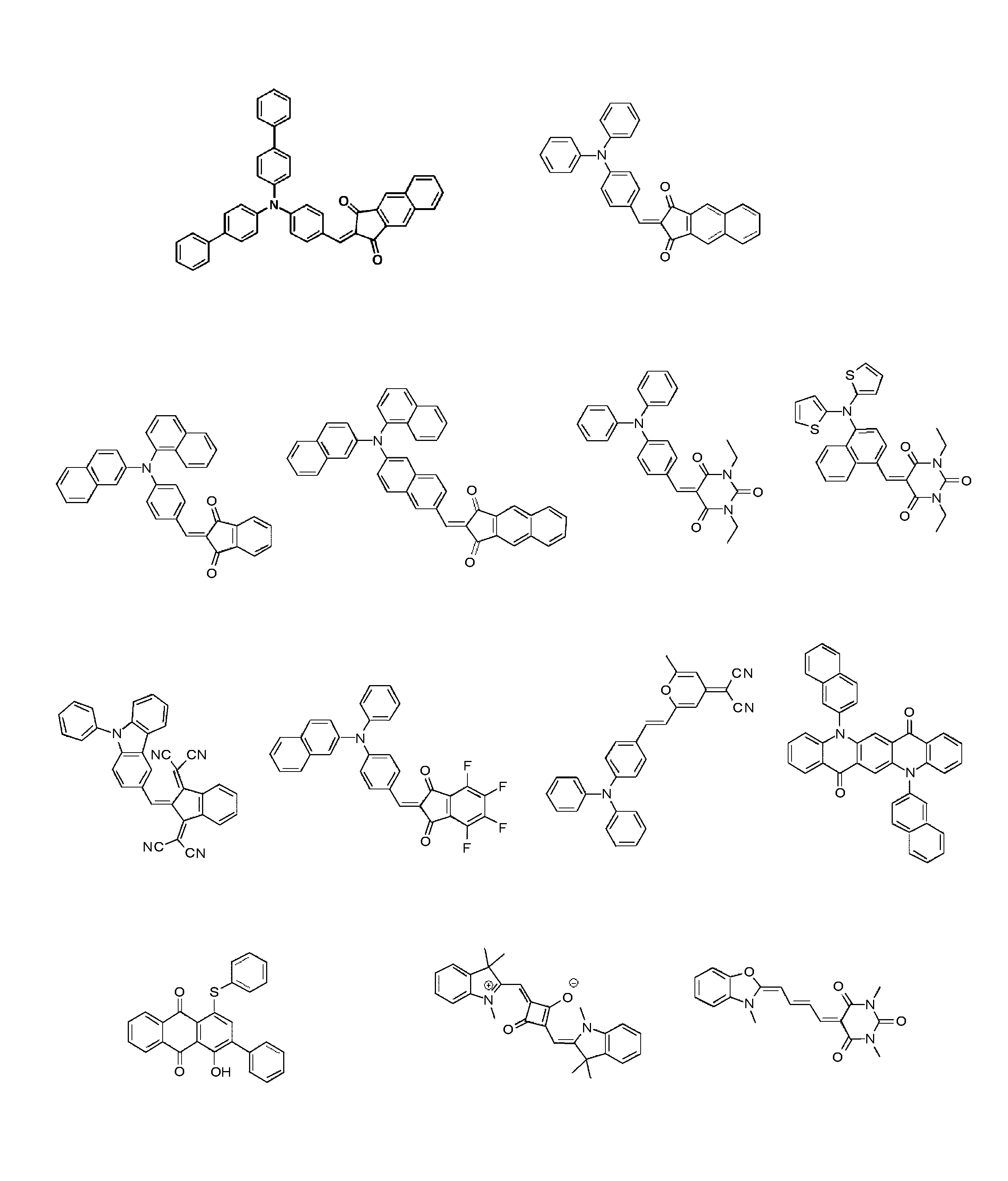
以下に、式(I)又は(II)で示される化合物の具体例を示すが、本発明はこれらに限定されるものではない。
以下に、式(I)又は(II)で示される化合物の具体例を示すが、本発明はこれらに限定されるものではない。
[置換基W]
以下に、置換基Wを列挙する。
アルキル基(好ましくは炭素数1~20で、例えばメチル、エチル、イソプロピル、t-ブチル、ペンチル、ヘプチル、1-エチルペンチル、ベンジル、2-エトキシエチル、1-カルボキシメチル、トリフルオロメチル等)、アルケニル基(好ましくは炭素数2~20で、例えば、ビニル、アリル、オレイル等)、アルキニル基(好ましくは炭素数2~20で、例えば、エチニル、ブタジイニル、フェニルエチニル等)、シクロアルキル基(好ましくは炭素数3~20で、例えば、シクロプロピル、シクロペンチル、シクロヘキシル、4-メチルシクロヘキシル等)、シクロアルケニル基(好ましくは炭素数5~20での、例えばシクロペンテニル、シクロヘキセニル等)、アリール基(好ましくは炭素数6~26で、例えば、フェニル、1-ナフチル、4-メトキシフェニル、2-クロロフェニル、3-メチルフェニル等)、ヘテロ環基(好ましくは炭素数2~20で、少なくとも1つの酸素原子、硫黄原子、窒素原子を有する5または6員環のヘテロ環基が好ましく、例えば、2-ピリジル、4-ピリジル、2-イミダゾリル、2-ベンゾイミダゾリル、2-チアゾリル、2-オキサゾリル等)、アルコキシ基(好ましくは炭素数1~20で、例えば、メトキシ、エトキシ、イソプロピルオキシ、ベンジルオキシ等)、アルケニルオキシ基(好ましくは炭素数2~20で、例えば、ビニルオキシ、アリルオキシ等)、アルキニルオキシ基(好ましくは炭素数2~20で、例えば、2-プロペニルオキシ、4-ブチニルオキシ等)、シクロアルキルオキシ基(好ましくは炭素数3~20で、例えば、シクロプロピルオキシ、シクロペンチルオキシ、シクロヘキシルオキシ、4-メチルシクロヘキシルオキシ等)、アリールオキシ基(好ましくは炭素数6~26で、例えば、フェノキシ、1-ナフチルオキシ、3-メチルフェノキシ、4-メトキシフェノキシ等)、ヘテロ環オキシ基(例えば、イミダゾリルオキシ、ベンゾイミダゾリルオキシ、チアゾリルオキシ、ベンゾチアゾリルオキシ、トリアジニルオキシ、プリニルオキシ)、
以下に、置換基Wを列挙する。
アルキル基(好ましくは炭素数1~20で、例えばメチル、エチル、イソプロピル、t-ブチル、ペンチル、ヘプチル、1-エチルペンチル、ベンジル、2-エトキシエチル、1-カルボキシメチル、トリフルオロメチル等)、アルケニル基(好ましくは炭素数2~20で、例えば、ビニル、アリル、オレイル等)、アルキニル基(好ましくは炭素数2~20で、例えば、エチニル、ブタジイニル、フェニルエチニル等)、シクロアルキル基(好ましくは炭素数3~20で、例えば、シクロプロピル、シクロペンチル、シクロヘキシル、4-メチルシクロヘキシル等)、シクロアルケニル基(好ましくは炭素数5~20での、例えばシクロペンテニル、シクロヘキセニル等)、アリール基(好ましくは炭素数6~26で、例えば、フェニル、1-ナフチル、4-メトキシフェニル、2-クロロフェニル、3-メチルフェニル等)、ヘテロ環基(好ましくは炭素数2~20で、少なくとも1つの酸素原子、硫黄原子、窒素原子を有する5または6員環のヘテロ環基が好ましく、例えば、2-ピリジル、4-ピリジル、2-イミダゾリル、2-ベンゾイミダゾリル、2-チアゾリル、2-オキサゾリル等)、アルコキシ基(好ましくは炭素数1~20で、例えば、メトキシ、エトキシ、イソプロピルオキシ、ベンジルオキシ等)、アルケニルオキシ基(好ましくは炭素数2~20で、例えば、ビニルオキシ、アリルオキシ等)、アルキニルオキシ基(好ましくは炭素数2~20で、例えば、2-プロペニルオキシ、4-ブチニルオキシ等)、シクロアルキルオキシ基(好ましくは炭素数3~20で、例えば、シクロプロピルオキシ、シクロペンチルオキシ、シクロヘキシルオキシ、4-メチルシクロヘキシルオキシ等)、アリールオキシ基(好ましくは炭素数6~26で、例えば、フェノキシ、1-ナフチルオキシ、3-メチルフェノキシ、4-メトキシフェノキシ等)、ヘテロ環オキシ基(例えば、イミダゾリルオキシ、ベンゾイミダゾリルオキシ、チアゾリルオキシ、ベンゾチアゾリルオキシ、トリアジニルオキシ、プリニルオキシ)、
アルコキシカルボニル基(好ましくは炭素数2~20ので、例えば、エトキシカルボニル、2-エチルヘキシルオキシカルボニル等)、シクロアルコキシカルボニル基(好ましくは炭素数4~20ので、例えば、シクロプロピルオキシカルボニル、シクロペンチルオキシカルボニル、シクロヘキシルオキシカルボニル等)、アリールオキシカルボニル基(好ましくは炭素数6~20で、例えば、フェニルオキシカルボニル、ナフチルオキシカルボニル等)、アミノ基(好ましくは炭素数0~20で、アルキルアミノ基、アルケニルアミノ基、アルキニルアミノ基、シクロアルキルアミノ基、シクロアルケニルアミノ基、アリールアミノ基、ヘテロ環アミノ基を含み、例えば、アミノ、N,N-ジメチルアミノ、N,N-ジエチルアミノ、N-エチルアミノ、N-アリルアミノ、N-(2-プロピニル)アミノ、N-シクロヘキシルアミノ、N-シクロヘキセニルアミノ、アニリノ、ピリジルアミノ、イミダゾリルアミノ、ベンゾイミダゾリルアミノ、チアゾリルアミノ、ベンゾチアゾリルアミノ、トリアジニルアミノ等)、スルファモイル基(好ましくは炭素数0~20で、アルキル、シクロアルキルもしくはアリールのスルファモイル基が好ましく、例えば、N,N-ジメチルスルファモイル、N-シクロヘキシルスルファモイル、N-フェニルスルファモイル等)、アシル基(好ましくは炭素数1~20で、例えば、アセチル、シクロヘキシルカルボニル、ベンゾイル等)、アシルオキシ基(好ましくは炭素数1~20で、例えば、アセチルオキシ、シクロヘキシルカルボニルオキシ、ベンゾイルオキシ等)、カルバモイル基(好ましくは炭素数1~20で、アルキル、シクロアルキルもしくはアリールのカルバモイル基が好ましく、例えば、N,N-ジメチルカルバモイル、N-シクロヘキシルカルバモイル、N-フェニルカルバモイル等)、
アシルアミノ基(好ましくは炭素数1~20のアシルアミノ基、例えば、アセチルアミノ、シクロヘキシルカルボニルアミノ、ベンゾイルアミノ等)、スルホンアミド基(好ましくは炭素数0~20で、アルキル、シクロアルキルもしくはアリールのスルホンアミド基が好ましく、例えば、メタンスルホンアミド、ベンゼンスルホンアミド、N-メチルメタンスルスルホンアミド、N-シクロヘキシルスルホンアミド、N-エチルベンゼンスルホンアミド等)、アルキルチオ基(好ましくは炭素数1~20で、例えば、メチルチオ、エチルチオ、イソプロピルチオ、ベンジルチオ等)、シクロアルキルチオ基(好ましくは炭素数3~20で、例えば、シクロプロピルチオ、シクロペンチルチオ、シクロヘキシルチオ、4-メチルシクロヘキシルチオ等)、アリールチオ基(好ましくは炭素数6~26で、例えば、フェニルチオ、1-ナフチルチオ、3-メチルフェニルチオ、4-メトキシフェニルチオ等)、アルキル、シクロアルキルもしくはアリールスルホニル基(好ましくは炭素数1~20で、例えば、メチルスルホニル、エチルスルホニル、シクロヘキシルスルホニル、ベンゼンスルホニル等)、
シリル基(好ましくは炭素数1~20で、アルキル、アリール、アルコキシおよびアリールオキシが置換したシリル基が好ましく、例えば、トリエチルシリル、トリフェニルシリル、ジエチルベンジルシリル、ジメチルフェニルシリル等)、シリルオキシ基(好ましくは炭素数1~20で、アルキル、アリール、アルコキシおよびアリールオキシが置換したシリルオキシ基が好ましく、例えば、トリエチルシリルオキシ、トリフェニルシリルオキシ、ジエチルベンジルシリルオキシ、ジメチルフェニルシリルオキシ等)、ヒドロキシル基、シアノ基、ニトロ基、ハロゲン原子(例えばフッ素原子、塩素原子、臭素原子、ヨウ素原子等)、カルボキシル基、スルホ基、ホスホニル基、ホスホリル基、ホウ酸基。
化合物ないし置換基等がアルキル基、アルケニル基等を含むとき、これらは直鎖状でも分岐状でもよく、置換されていても無置換でもよい。またアリール基、ヘテロ環基等を含むとき、それらは単環でも縮環でもよく、置換されていても無置換でもよい。
本明細書において、単に置換基としてしか記載されていないものは、この置換基Wを参照するものであり、また、各々の基が記載されているだけのとき(例えば、「アルキル基」と記載されているだけの時)は、この置換基Wの対応する基における好ましい範囲、具体例が適用される。
本明細書において、単に置換基としてしか記載されていないものは、この置換基Wを参照するものであり、また、各々の基が記載されているだけのとき(例えば、「アルキル基」と記載されているだけの時)は、この置換基Wの対応する基における好ましい範囲、具体例が適用される。
[環RI]
環RIは芳香族、又は非芳香族の炭化水素環、又は複素環や、これらが更に組み合わされて形成された多環縮合環が挙げられる。例えば、ベンゼン環、ナフタレン環、アントラセン環、フェナントレン環、フルオレン環、トリフェニレン環、ナフタセン環、ビフェニル環、ピロール環、フラン環、チオフェン環、イミダゾール環、オキサゾール環、チアゾール環、ピリジン環、ピラジン環、ピリミジン環、ピリダジン環、インドリジン環、インドール環、ベンゾフラン環、ベンゾチオフェン環、イソベンゾフラン環、キノリジン環、キノリン環、フタラジン環、ナフチリジン環、キノキサリン環、キノキサゾリン環、イソキノリン環、カルバゾール環、フェナントリジン環、アクリジン環、フェナントロリン環、チアントレン環、クロメン環、キサンテン環、フェノキサチイン環、フェノチアジン環、及びフェナジン環が挙げられる。
環RIは芳香族、又は非芳香族の炭化水素環、又は複素環や、これらが更に組み合わされて形成された多環縮合環が挙げられる。例えば、ベンゼン環、ナフタレン環、アントラセン環、フェナントレン環、フルオレン環、トリフェニレン環、ナフタセン環、ビフェニル環、ピロール環、フラン環、チオフェン環、イミダゾール環、オキサゾール環、チアゾール環、ピリジン環、ピラジン環、ピリミジン環、ピリダジン環、インドリジン環、インドール環、ベンゾフラン環、ベンゾチオフェン環、イソベンゾフラン環、キノリジン環、キノリン環、フタラジン環、ナフチリジン環、キノキサリン環、キノキサゾリン環、イソキノリン環、カルバゾール環、フェナントリジン環、アクリジン環、フェナントロリン環、チアントレン環、クロメン環、キサンテン環、フェノキサチイン環、フェノチアジン環、及びフェナジン環が挙げられる。
以下に実施例に基づき本発明をさらに詳細に説明するが、本発明はこれらに限定されるものではない。
[昇華精製装置のコンダクタンスの測定]
図1~4に示される形態の昇華精製装置において、図5に示すように、昇華管(13)の、X側末端部Aに圧力計GAを、配管(12)と昇華管(13)との接続部Bに圧力計GBを、配管(12)と真空ポンプ(11)との接続部Cに圧力計GCをそれぞれ設置した。また、配管には図6に示すように調節弁(18)を設けた。
上記昇華管は円筒形の石英ガラス管であり、その管内断面積を78.5cm2、軸方向の長さを100cmとした。また、上記配管はSUS製(電界研磨処理ステンレス)で断面円形のホース状のものを採用し、その管内断面積を81cm2、長さを50cmとした。上記圧力計GA~GCとしてTG201C(アンペール社製)を使用した。
図1~4に示される形態の昇華精製装置において、図5に示すように、昇華管(13)の、X側末端部Aに圧力計GAを、配管(12)と昇華管(13)との接続部Bに圧力計GBを、配管(12)と真空ポンプ(11)との接続部Cに圧力計GCをそれぞれ設置した。また、配管には図6に示すように調節弁(18)を設けた。
上記昇華管は円筒形の石英ガラス管であり、その管内断面積を78.5cm2、軸方向の長さを100cmとした。また、上記配管はSUS製(電界研磨処理ステンレス)で断面円形のホース状のものを採用し、その管内断面積を81cm2、長さを50cmとした。上記圧力計GA~GCとしてTG201C(アンペール社製)を使用した。
真空ポンプを作動させて、圧力計GA~GCのすべてが1×10⁻²Pa以下を示して安定したことを確認した後、図5に示されるようなX側末端部に設けたガス導入口から、マスフローコントローラーを用いて一定量のアルゴンガスを導入し、圧力計GA~GCが示す値が安定したところで、圧力計GA~GCが示す圧力を読み取った。
上記測定において、アルゴンガスの導入は、導入流量を3.3×10⁻⁹m3/秒、6.7×10-9m3/秒、1.0×10-8m3/秒、1.7×10-8m3/秒、及び3.3×10-8m3/秒に設定し、それぞれの流量において、圧力計GA~GCの値を読み取った。得られた値を上記式(1)及び(2)に当てはめ、AC間のコンダクタンスKAC、及びBC間のコンダクタンスKBCを求めた。ここで、KAC及びKBCはそれぞれ、アルゴンガスの上記5種の流量における各KAC及びKBCの平均値とした。
上記測定において、アルゴンガスの導入は、導入流量を3.3×10⁻⁹m3/秒、6.7×10-9m3/秒、1.0×10-8m3/秒、1.7×10-8m3/秒、及び3.3×10-8m3/秒に設定し、それぞれの流量において、圧力計GA~GCの値を読み取った。得られた値を上記式(1)及び(2)に当てはめ、AC間のコンダクタンスKAC、及びBC間のコンダクタンスKBCを求めた。ここで、KAC及びKBCはそれぞれ、アルゴンガスの上記5種の流量における各KAC及びKBCの平均値とした。
[試験例1]
図6に示す調節弁(18)の開閉度を調節すること、及び昇華管内に断面積5~50cm2、軸方向の長さ5~10cmの石英ガラス製円筒を設置することで、上記昇華精製装置のコンダクタンスを下記表1に示す値に調節した。
各コンダクタンスを示す昇華精製装置(実施例1~14、比較例1~7)を用いて、常法により合成した下記化合物Aを粗体試料として下記手法により昇華精製を行った。化合物Aは不純物として合成時に生成した副生成物だけでなく、使用した原料、原料分解物、溶媒、水、無機物等を含みうる。
図6に示す調節弁(18)の開閉度を調節すること、及び昇華管内に断面積5~50cm2、軸方向の長さ5~10cmの石英ガラス製円筒を設置することで、上記昇華精製装置のコンダクタンスを下記表1に示す値に調節した。
各コンダクタンスを示す昇華精製装置(実施例1~14、比較例1~7)を用いて、常法により合成した下記化合物Aを粗体試料として下記手法により昇華精製を行った。化合物Aは不純物として合成時に生成した副生成物だけでなく、使用した原料、原料分解物、溶媒、水、無機物等を含みうる。

粗体100gを図6に示すように昇華部(14)に配設した。真空ポンプ(11)を作動させて圧力計GA~GCのすべてが5×10⁻³Paになるまで減圧した後、熱源としてパイプヒーター(17)を用いて昇華部(14)を325℃に加熱して、昇華管(13)のY側末端に向けて徐々に温度が低下するようにして昇華精製を行った(昇華管内のY側末端の温度:100℃)。なお、図1~6に示されるように、昇華管(13)は黄銅製の金属管(16)の中に配設され、この金属管(16)を取り巻くように熱源(17)を配設した。
10時間経過後に加熱を止め、昇華管全体が室温になるまで冷却してから大気開放して、昇華精製物と昇華残留物を取り出し、その質量を測定した。結果を表1に示す。
10時間経過後に加熱を止め、昇華管全体が室温になるまで冷却してから大気開放して、昇華精製物と昇華残留物を取り出し、その質量を測定した。結果を表1に示す。

表1に示されるように、昇華精製装置のKACを0.010m3/秒以上とすることで、昇華精製効率が大きく向上することがわかった。さらに、昇華精製装置のKBCを0.02m3/秒以上とすることで、昇華精製効率がより向上することがわかった。これらの現象は、本発明で規定するコンダクタンス値を示す昇華精製装置を用いることで、気体の発生に伴う真空度の低下が抑えられ、その結果、昇華と競争関係にある熱分解が抑制されたことが一因と考えられる。
[試験例2]
図6に示す調節弁(18)の開閉度を調節すること、及び昇華管内に断面積5~50cm2、軸方向の長さ5~10cmの石英ガラス製円筒を設置することで、上記昇華精製装置のコンダクタンスを下記表2に示す値に調節した。
常法により合成した下記化合物B~Eを粗体試料として下記手法により昇華精製を行った。化合物B~Eは不純物として合成時に生成した副生成物だけでなく、使用した原料、原料分解物、溶媒、水、無機物等を含みうる。
図6に示す調節弁(18)の開閉度を調節すること、及び昇華管内に断面積5~50cm2、軸方向の長さ5~10cmの石英ガラス製円筒を設置することで、上記昇華精製装置のコンダクタンスを下記表2に示す値に調節した。
常法により合成した下記化合物B~Eを粗体試料として下記手法により昇華精製を行った。化合物B~Eは不純物として合成時に生成した副生成物だけでなく、使用した原料、原料分解物、溶媒、水、無機物等を含みうる。
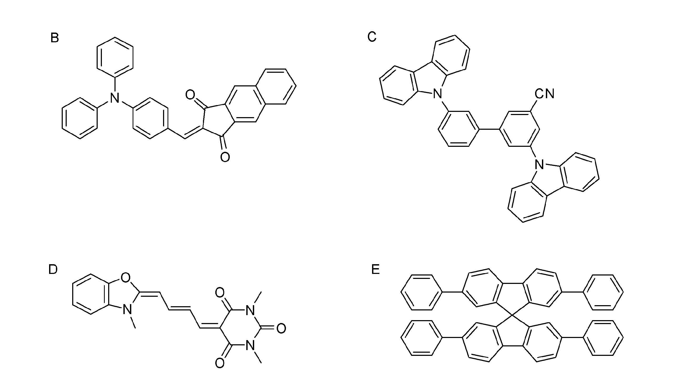
粗体10gを図6に示すように昇華部(14)に配設した。真空ポンプ(11)を作動させて圧力計GA~GCのすべてが5×10⁻³Paになるまで減圧した後、熱源としてパイプヒーター(17)を用いて昇華部(14)を表2記載の温度に加熱して、昇華管(13)のY側末端に向けて徐々に温度が低下するようにして昇華精製を行った(昇華管内のY側末端の温度:100℃)。なお、図1~6に示されるように、昇華管(13)は黄銅製の金属管(16)の中に配設され、この金属管(16)を取り巻くように熱源(17)を配設した。
3時間経過後に加熱を止め、昇華管全体が室温になるまで冷却してから大気開放して、昇華精製物と昇華残留物を取り出し、その質量を測定した。結果を表2に示す。
3時間経過後に加熱を止め、昇華管全体が室温になるまで冷却してから大気開放して、昇華精製物と昇華残留物を取り出し、その質量を測定した。結果を表2に示す。
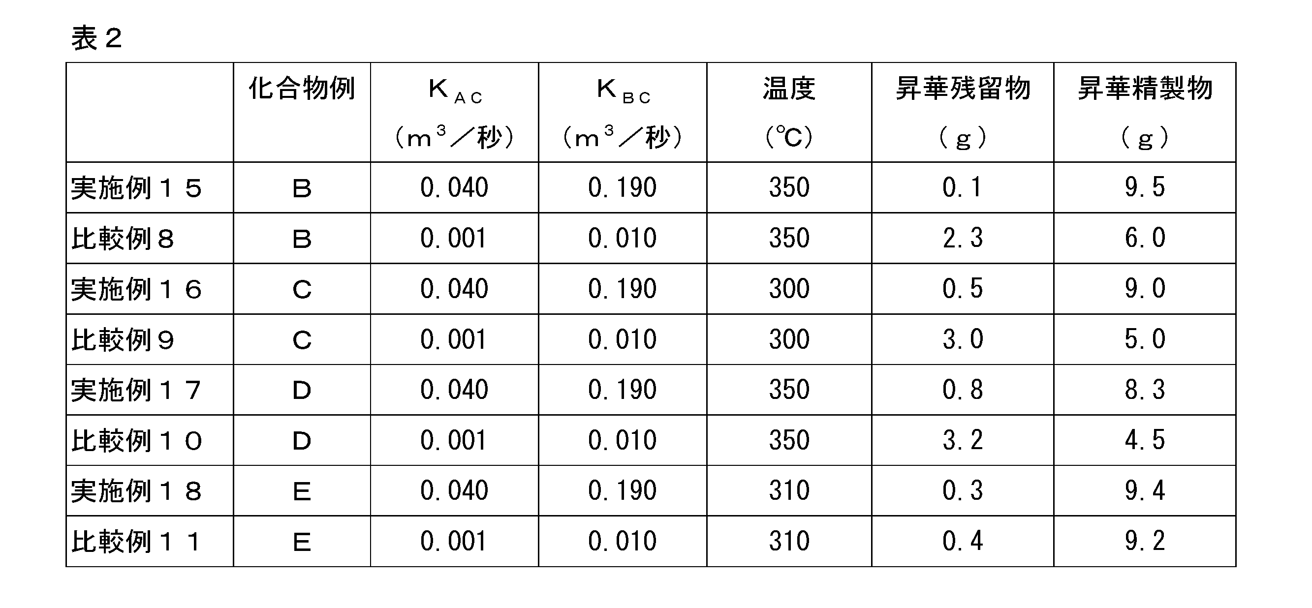
表2に示されるように、本発明で規定するコンダクタンスを示す昇華精製装置を用いることにより、いずれの化合物を昇華精製対象として用いても、昇華残留物が少なく昇華精製効率に優れていた。
[試験例3]
化合物A~Eについて、熱重量測定装置を用いて、常圧の窒素雰囲気下、試験例1又は2に記載の各化合物の昇華温度に5時間保ったときの質量減少率を測定した。結果を表3に示す。
化合物A~Eについて、熱重量測定装置を用いて、常圧の窒素雰囲気下、試験例1又は2に記載の各化合物の昇華温度に5時間保ったときの質量減少率を測定した。結果を表3に示す。
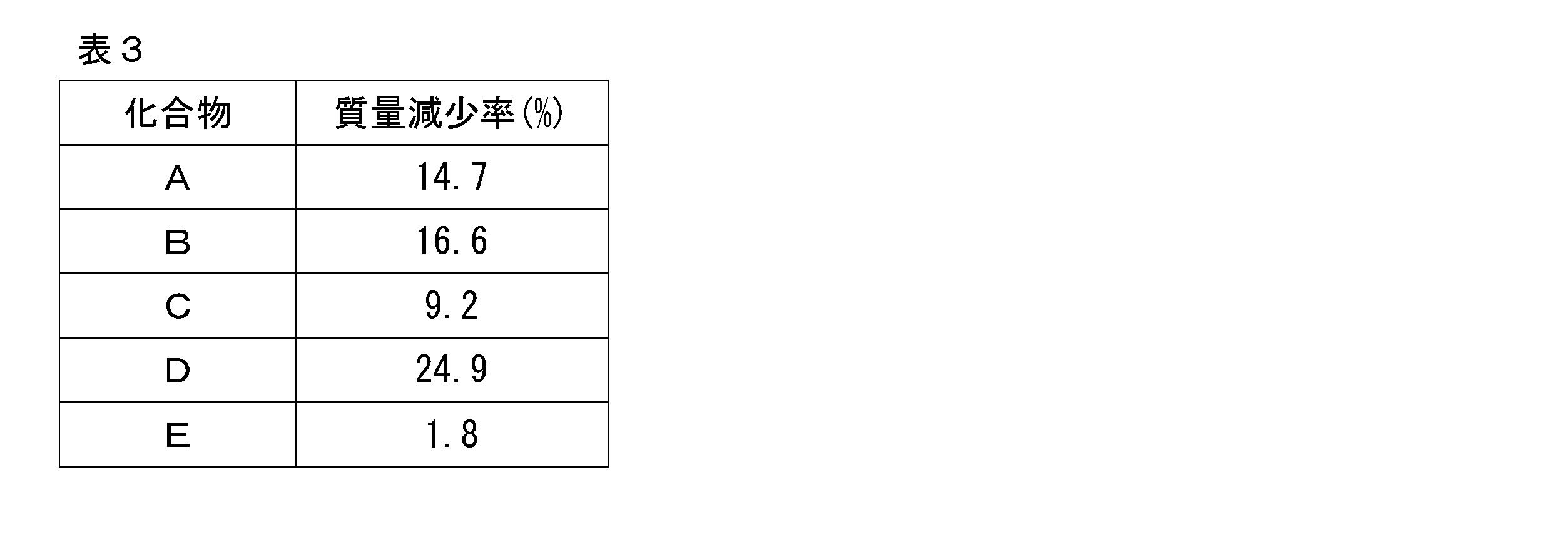
上述のように、表1、2の結果から、本発明の方法に依らない比較例と本発明に基づく実施例の間で昇華精製物量および昇華残留物量を比べると、化合物Aについての実施例1~14と比較例1~7、化合物Bについての実施例15と比較例8、化合物Cについての実施例16と比較例9、化合物Dについての実施例17と比較例10の比較においては、いずれも本発明に基づく実施例の場合に昇華精製物量が大幅に多くなり、これに伴い昇華残留物量は大幅に少なくなった。化合物A~Dは熱安定が低い化合物であることから(表3)、本発明の昇華精製装置を用いることで、昇華精製対象試料の熱安定性によらず、昇華精製を効率的に行えることが示された。
コンダクタンス値を指標に昇華精製装置を設計し、これを用いることで効率的な昇華精製を実現するという技術思想は従来にはないものである。
本発明をその実施態様とともに説明したが、我々は特に指定しない限り我々の発明を説明のどの細部においても限定しようとするものではなく、添付の請求の範囲に示した発明の精神と範囲に反することなく幅広く解釈されるべきであると考える。
本願は、2013年2月14日に日本国で特許出願された特願2013-027072及び2013年8月29日に日本国で特許出願された特願2013-178643に基づく優先権を主張するものであり、これらはここに参照してその内容を本明細書の記載の一部として取り込む。
10 昇華精製装置
11 真空ポンプ
12 配管
13 昇華管
14 昇華部(粗体)
15 捕集部
16 金属管
17 熱源
18 調節弁
19 導入管(導入口)
11 真空ポンプ
12 配管
13 昇華管
14 昇華部(粗体)
15 捕集部
16 金属管
17 熱源
18 調節弁
19 導入管(導入口)
Claims (7)
- 昇華管と、真空ポンプと、該昇華管と該真空ポンプとを繋ぐ配管とを有する昇華精製装置であって、
前記昇華管の、前記真空ポンプから離れた側の末端部をAとし、前記配管と前記真空ポンプとの接続部をCとしたとき、AからCまでのコンダクタンスKACが0.01m3/秒以上である、昇華精製装置。 - 前記昇華管と前記配管との接続部をBとしたとき、BからCまでのコンダクタンスKBCが0.02m3/秒以上である、請求項1に記載の昇華精製装置。
- 前記KACが0.02m3/秒以上である、請求項1又は2に記載の昇華精製装置。
- 前記KBCが0.03m3/秒以上である、請求項1~3のいずれか1項に記載の昇華精製装置。
- 前記昇華管の真空ポンプから離れた側の末端部が閉じている、請求項1~4のいずれか1項に記載の昇華精製装置。
- 請求項1~5のいずれか1項に記載の昇華精製装置を用いた昇華精製方法であって、不活性ガス雰囲気中、常圧下、昇華温度に5時間保ったときの質量減少率が2%以上である試料を昇華精製対象試料とする、昇華精製方法。
- 前記昇華精製対象試料が、不活性ガス雰囲気中、常圧下、昇華温度に5時間保ったときの質量減少率が10%以上である、請求項6に記載の昇華精製方法。
Applications Claiming Priority (4)
| Application Number | Priority Date | Filing Date | Title |
|---|---|---|---|
| JP2013-027072 | 2013-02-14 | ||
| JP2013027072 | 2013-02-14 | ||
| JP2013178643A JP2014176838A (ja) | 2013-02-14 | 2013-08-29 | 昇華精製装置 |
| JP2013-178643 | 2013-08-29 |
Publications (1)
| Publication Number | Publication Date |
|---|---|
| WO2014125918A1 true WO2014125918A1 (ja) | 2014-08-21 |
Family
ID=51353928
Family Applications (1)
| Application Number | Title | Priority Date | Filing Date |
|---|---|---|---|
| PCT/JP2014/051799 Ceased WO2014125918A1 (ja) | 2013-02-14 | 2014-01-28 | 昇華精製装置及び昇華精製方法 |
Country Status (2)
| Country | Link |
|---|---|
| JP (1) | JP2014176838A (ja) |
| WO (1) | WO2014125918A1 (ja) |
Cited By (2)
| Publication number | Priority date | Publication date | Assignee | Title |
|---|---|---|---|---|
| RU169600U1 (ru) * | 2016-10-14 | 2017-03-24 | Федеральное государственное бюджетное образовательное учреждение высшего образования "Российский химико-технологический университет имени Д.И. Менделеева" (РХТУ им. Д.И. Менделеева) | Реактор для очистки твердых веществ методом вакуумной сублимации |
| CN109030542A (zh) * | 2017-06-09 | 2018-12-18 | 武汉尚赛光电科技有限公司 | 一种有机材料热稳定性测试设备 |
Citations (3)
| Publication number | Priority date | Publication date | Assignee | Title |
|---|---|---|---|---|
| JP2000256877A (ja) * | 1999-03-09 | 2000-09-19 | Agency Of Ind Science & Technol | 有機薄膜作製方法および有機薄膜作製装置 |
| WO2001018149A1 (fr) * | 1999-09-02 | 2001-03-15 | Nippon Steel Chemical Co., Ltd. | Materiau organique electroluminescent |
| JP2012224618A (ja) * | 2011-04-08 | 2012-11-15 | Fujifilm Corp | 有機材料の精製方法、有機エレクトロニクス用材料、光電変換素子、光センサ、撮像素子、及び有機電界発光素子 |
Family Cites Families (3)
| Publication number | Priority date | Publication date | Assignee | Title |
|---|---|---|---|---|
| JP4632601B2 (ja) * | 2001-09-18 | 2011-02-16 | 三井化学株式会社 | 昇華精製装置、昇華精製方法および有機電界発光素子の製造方法 |
| US7820981B2 (en) * | 2003-12-12 | 2010-10-26 | Semequip, Inc. | Method and apparatus for extending equipment uptime in ion implantation |
| JP4542607B1 (ja) * | 2009-08-31 | 2010-09-15 | 富士フイルム株式会社 | イリジウム錯体を昇華精製する方法、及び有機電界発光素子の製造方法 |
-
2013
- 2013-08-29 JP JP2013178643A patent/JP2014176838A/ja active Pending
-
2014
- 2014-01-28 WO PCT/JP2014/051799 patent/WO2014125918A1/ja not_active Ceased
Patent Citations (3)
| Publication number | Priority date | Publication date | Assignee | Title |
|---|---|---|---|---|
| JP2000256877A (ja) * | 1999-03-09 | 2000-09-19 | Agency Of Ind Science & Technol | 有機薄膜作製方法および有機薄膜作製装置 |
| WO2001018149A1 (fr) * | 1999-09-02 | 2001-03-15 | Nippon Steel Chemical Co., Ltd. | Materiau organique electroluminescent |
| JP2012224618A (ja) * | 2011-04-08 | 2012-11-15 | Fujifilm Corp | 有機材料の精製方法、有機エレクトロニクス用材料、光電変換素子、光センサ、撮像素子、及び有機電界発光素子 |
Cited By (2)
| Publication number | Priority date | Publication date | Assignee | Title |
|---|---|---|---|---|
| RU169600U1 (ru) * | 2016-10-14 | 2017-03-24 | Федеральное государственное бюджетное образовательное учреждение высшего образования "Российский химико-технологический университет имени Д.И. Менделеева" (РХТУ им. Д.И. Менделеева) | Реактор для очистки твердых веществ методом вакуумной сублимации |
| CN109030542A (zh) * | 2017-06-09 | 2018-12-18 | 武汉尚赛光电科技有限公司 | 一种有机材料热稳定性测试设备 |
Also Published As
| Publication number | Publication date |
|---|---|
| JP2014176838A (ja) | 2014-09-25 |
Similar Documents
| Publication | Publication Date | Title |
|---|---|---|
| JP4572113B2 (ja) | スピロビフルオレン誘導体、それらの調製とその用途 | |
| TWI695899B (zh) | 用於真空熱蒸鍍經取代之1,2,3-三亞基三(氰甲基亞基)環丙烷與使用它們之電子裝置及半導體材料 | |
| CN101939325A (zh) | 有机半导体材料 | |
| CN109776566B (zh) | 一种基于多取代苯并环戊二酮衍生物的a-d-a共轭分子及其应用 | |
| TWI695007B (zh) | 一種四齒鉑(ii)配合物及應用 | |
| TW201930332A (zh) | 一種基於惡唑、噻唑或咪唑的四齒鉑(ii)配合物材料及應用 | |
| Senevirathna et al. | Synthesis, characterization and photovoltaic properties of azadipyrromethene-based acceptors: effect of pyrrolic substituents | |
| Broman et al. | Tetraceno [2, 1, 12, 11-opqra] tetracene-extended tetrathiafulvalene–redox-controlled generation of a large PAH core | |
| TW201930331A (zh) | 一種含四齒鉑(ii)配合物的有機電致發光器件 | |
| Yang et al. | Marked effects of indolyl vs. indolinyl substituent on solid-state structure, carrier mobility and photovoltaic efficiency of asymmetrical squaraine dyes | |
| WO2014125918A1 (ja) | 昇華精製装置及び昇華精製方法 | |
| Chang et al. | Carbazole-based small molecules for vacuum-deposited organic photovoltaic devices with open-circuit voltage exceeding 1 V | |
| WO2014125917A1 (ja) | 昇華精製方法 | |
| Um et al. | High-performance organic semiconductors for thin-film transistors based on 2, 7-divinyl [1] benzothieno [3, 2-b] benzothiophene | |
| KR102931319B1 (ko) | 광전 변환 소자, 촬상 소자, 광 센서, 화합물 | |
| KR102033126B1 (ko) | 유기 정공 수송 재료 | |
| JP2015189679A (ja) | 有機化合物の精製方法、光電変換素子、光センサ、及び有機電界発光素子 | |
| Yang et al. | Unsymmetrical squaraines with new linkage manner for high-performance solution-processed small-molecule organic photovoltaic cells | |
| CN108912044A (zh) | 一种铜催化烯基叠氮合成多取代吡啶的方法 | |
| Nishida et al. | Preparation, physical properties and n-type FET characteristics of substituted diindenopyrazinediones and bis (dicyanomethylene) derivatives | |
| Romanova et al. | Novel indolin-2-one-substituted methanofullerenes bearing long n-alkyl chains: synthesis and application in bulk-heterojunction solar cells | |
| JP4065874B2 (ja) | 有機薄膜トランジスタ及びその製造方法 | |
| Li et al. | Hole-transporting material based on spirobifluorene unit with perfect amorphous and high stability for efficient OLEDs | |
| Fu et al. | Synthesis and electroluminescence properties of benzothiazole derivatives | |
| JP2011222974A (ja) | 有機半導体材料及び有機半導体素子 |
Legal Events
| Date | Code | Title | Description |
|---|---|---|---|
| 121 | Ep: the epo has been informed by wipo that ep was designated in this application |
Ref document number: 14751376 Country of ref document: EP Kind code of ref document: A1 |
|
| NENP | Non-entry into the national phase |
Ref country code: DE |
|
| 122 | Ep: pct application non-entry in european phase |
Ref document number: 14751376 Country of ref document: EP Kind code of ref document: A1 |