WO2014125865A1 - 移動指示装置、コンピュータプログラム、移動指示方法及び移動体システム - Google Patents
移動指示装置、コンピュータプログラム、移動指示方法及び移動体システム Download PDFInfo
- Publication number
- WO2014125865A1 WO2014125865A1 PCT/JP2014/050740 JP2014050740W WO2014125865A1 WO 2014125865 A1 WO2014125865 A1 WO 2014125865A1 JP 2014050740 W JP2014050740 W JP 2014050740W WO 2014125865 A1 WO2014125865 A1 WO 2014125865A1
- Authority
- WO
- WIPO (PCT)
- Prior art keywords
- coordinate value
- coordinate
- movement
- point
- line segment
- Prior art date
- Legal status (The legal status is an assumption and is not a legal conclusion. Google has not performed a legal analysis and makes no representation as to the accuracy of the status listed.)
- Ceased
Links
Images












Classifications
-
- G—PHYSICS
- G08—SIGNALLING
- G08C—TRANSMISSION SYSTEMS FOR MEASURED VALUES, CONTROL OR SIMILAR SIGNALS
- G08C21/00—Systems for transmitting the position of an object with respect to a predetermined reference system, e.g. tele-autographic system
-
- G—PHYSICS
- G05—CONTROLLING; REGULATING
- G05D—SYSTEMS FOR CONTROLLING OR REGULATING NON-ELECTRIC VARIABLES
- G05D1/00—Control of position, course, altitude or attitude of land, water, air or space vehicles, e.g. using automatic pilots
- G05D1/0011—Control of position, course, altitude or attitude of land, water, air or space vehicles, e.g. using automatic pilots associated with a remote control arrangement
- G05D1/0016—Control of position, course, altitude or attitude of land, water, air or space vehicles, e.g. using automatic pilots associated with a remote control arrangement characterised by the operator's input device
-
- G—PHYSICS
- G05—CONTROLLING; REGULATING
- G05D—SYSTEMS FOR CONTROLLING OR REGULATING NON-ELECTRIC VARIABLES
- G05D1/00—Control of position, course, altitude or attitude of land, water, air or space vehicles, e.g. using automatic pilots
- G05D1/0011—Control of position, course, altitude or attitude of land, water, air or space vehicles, e.g. using automatic pilots associated with a remote control arrangement
- G05D1/0038—Control of position, course, altitude or attitude of land, water, air or space vehicles, e.g. using automatic pilots associated with a remote control arrangement by providing the operator with simple or augmented images from one or more cameras located onboard the vehicle, e.g. tele-operation
Definitions
- the present invention relates to a movement instruction apparatus, a computer program, a movement instruction method, and a moving body system that give a moving direction instruction to a moving body that can move in all directions.
- Patent Documents 1 and 2 Conventionally, moving bodies that can move in all directions have been proposed (Patent Documents 1 and 2). Also, a cross key is known as an operation device for instructing the moving direction of the moving body.
- the present invention has been made in view of the above-described circumstances, and an object thereof is to provide a movement instruction device or the like that can intuitively instruct rotation movement to a moving body.
- a movement instruction apparatus is a movement instruction apparatus that includes a coordinate input device and an instruction unit that gives a movement instruction to a moving body that performs rotational movement.
- the movement instruction device receives a first coordinate value input from the coordinate input device.
- a second receiving unit that receives an input of a coordinate value, a second determining unit that periodically determines whether there is a change in the second coordinate value, and the first determining unit that determines that there is no change in the first coordinate value
- the second determination unit determines that there is no change in the second coordinate value after the second determination unit determines that the second coordinate value is changed
- the second coordinate value is changed.
- a stop point receiving unit for receiving a stop point coordinate value from the coordinate input device;
- a calculation unit for calculating an angle formed by a line segment formed by the initial coordinate values of the first coordinate value and the second coordinate value and a line segment formed by the first coordinate value and the stop point coordinate value,
- the instructing unit is configured to instruct the moving body to rotate and move based on the calculated angle.
- a stop point coordinate value of the second coordinate value is received from the coordinate input device, An angle formed by the line segment formed by the initial coordinate values of the first coordinate value and the second coordinate value and the line segment formed by the first coordinate value and the stop point coordinate value is calculated, and the moving object is calculated based on the calculated angle. Since the rotational movement instruction is given, the operator can intuitively give the rotational movement instruction to the moving body.
- the instruction unit is configured to instruct the moving body to stop rotational movement.
- the moving body when it is determined that there is no change in the first coordinate value and it is determined that the second coordinate value has not been input, the moving body is instructed to stop the rotational movement.
- the operator can intuitively give an instruction to stop the rotational movement.
- the first determination unit determines that there is no change in the first coordinate value
- the second determination unit determines that the second coordinate value has further changed from the stop point coordinate value.
- a second stop that accepts the second stop point coordinate value after the change of the second coordinate value from the coordinate input device.
- a point reception unit, and a line segment determination unit that determines whether the second stop point coordinate value is on a line segment formed by the first coordinate value and the initial coordinate value of the second coordinate value.
- the instruction unit instructs the moving body to stop rotational movement.
- the moving body is instructed to stop the rotational movement. Therefore, the operator can intuitively give an instruction to stop the rotational movement.
- the moving body performs translational movement
- the calculation unit calculates a direction and a length of a line segment formed by a predetermined coordinate value and the first coordinate value
- the instructing unit is configured to instruct the moving body to translate based on the calculated direction and length.
- the direction and length of the line segment formed by the predetermined coordinate value and the first coordinate value are calculated, and the moving body is instructed to translate based on the calculated direction and length. Therefore, the operator can intuitively instruct the direction and speed of translation.
- the operator when it is determined that there is no change in the first coordinate value after it is determined that there is a change in the first coordinate value, and the first coordinate value after the change matches the predetermined coordinate value, Since the mobile body is instructed to stop the translational movement, the operator can instruct the translational movement stop intuitively.
- the instruction unit when the first determination unit determines that the first coordinate value is not input, the instruction unit instructs the moving body to stop translational movement and to stop rotational movement. It is characterized by that.
- the moving body when it is determined that the first coordinate value has not been input, the moving body is instructed to stop the translational movement and to stop the rotational movement. It is possible for the operator to perform intuitively.
- the first determination unit determines that the first coordinate value has changed
- the second determination unit determines that the second coordinate value has changed from the stop point coordinate value.
- a parallel receiving unit that receives the third coordinate value and the fourth coordinate value after the change of the first coordinate value and the second coordinate value from the coordinate input device, and the first coordinate value and the stop point, respectively.
- the calculation unit sets the line segment formed by the predetermined coordinate value and the third coordinate value. The direction and length are calculated, and the instruction unit instructs the mobile body to translate based on the calculated direction and length.
- the three coordinate values after the change of the first coordinate value and the second coordinate value and the second coordinate value are received from the coordinate input device.
- the predetermined coordinate value and the third coordinate are calculated, and the translation is instructed to the moving body based on the calculated direction and length, so the operator can intuitively change the direction of the translation. Can be performed.
- the movement instruction device is characterized in that the coordinate input device is a track pad.
- the movement instruction device can be configured with general-purpose parts.
- the movement instruction device is characterized in that the coordinate input device is a touch panel.
- the movement instruction device can be configured with general-purpose parts.
- the movement instruction device includes a display unit, the touch panel is provided to cover a display surface of the display unit, and a line segment image formed by the first coordinate value and the second coordinate value is displayed on the display unit.
- the display unit is provided, the touch panel is provided so as to cover the display surface of the display unit, the line segment image formed by the first coordinate value and the second coordinate value is displayed on the display unit, and the stop point
- the coordinate value is received, since the arc image connecting the initial coordinate value of the second coordinate value and the stop point coordinate value is displayed on the display unit, the operator can visually check the touched position, Operability is improved.
- a computer program according to the present invention is a computer program that causes a computer to execute a movement instruction for a moving body that performs rotational movement, determines a change in a first coordinate value acquired from a coordinate input device, and acquires the first coordinate value. After determining the change of the second coordinate value acquired from the coordinate input device later, determining that the first coordinate value has not changed, and detecting that the second coordinate value has changed, the second coordinate value When it is determined that there is no change, the stop point coordinate value after the change of the second coordinate value is acquired from the coordinate input device, and a line formed by the initial coordinate value of the first coordinate value and the second coordinate value is formed. And an angle formed by a line segment formed by the first coordinate value and the stop point coordinate value is calculated, and the moving body is instructed to rotate and move based on the calculated angle. To.
- the movement instruction method is a movement instruction method by a movement instruction device that issues a movement instruction to a moving body that performs rotational movement. And after obtaining the first coordinate value, obtain a second coordinate value from the coordinate input device, determine a change in the second coordinate value, determine that the first coordinate value is not changed, When it is determined that there is no change in the second coordinate value after detecting that the second coordinate value has changed, the stop point coordinate value after the change in the second coordinate value is acquired from the coordinate input device, An angle formed by a line segment formed by the initial coordinate values of the first coordinate value and the second coordinate value and a line segment formed by the first coordinate value and the stop point coordinate value is calculated, and based on the calculated angle, the angle Instructing the moving body to rotate And wherein the door.
- a moving body system is a moving body system including a moving body and any one of the movement instruction devices described above, wherein the moving body moves based on an instruction from the movement instruction device. It is characterized by being.
- the operator can intuitively instruct the rotational movement to the moving body.
- the stop point coordinate value after the change in the second coordinate value is obtained from the coordinate input device.
- the operator can intuitively give the rotational movement instruction to the moving body.
- FIG. 1 is a diagram illustrating a configuration example of a mobile system according to Embodiment 1.
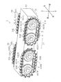
- FIG. 2 is a perspective view of an omnidirectional mobile trolley according to Embodiment 1.
- FIG. It is a top view of the omnidirectional mobile trolley except a some roller.
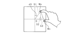
- FIG. 10 is an explanatory diagram for a movement instruction operation in the second embodiment.
- FIG. 10 is an explanatory diagram for a movement instruction operation in the second embodiment.
- FIG. 10 is an explanatory diagram for a movement instruction operation in the second embodiment.
- FIG. 10 is an explanatory diagram for a movement instruction operation in the second embodiment.
- FIG. 10 is an explanatory diagram for a movement instruction operation in the second embodiment.
- FIG. 10 is an explanatory diagram illustrating an example of a display mode of a display unit during a movement instruction operation in Embodiment 2.
- FIG. 10 is an explanatory diagram illustrating an example of a display mode of a display unit during a movement instruction operation in Embodiment 2.
- FIG. 10 is an explanatory diagram illustrating an example of a display mode of a display unit during a movement instruction operation in Embodiment 3.
- FIG. 10 is an explanatory diagram illustrating an example of a display mode of a display unit during a movement instruction operation in Embodiment 3.
- FIG. 10 is an explanatory diagram illustrating an example of a display mode of a display unit during a movement instruction operation in Embodiment 3.
- FIG. 10 is an explanatory diagram illustrating an example of a display mode of a display unit during a movement instruction operation in Embodiment 3.
- FIG. 10 is an explanatory diagram illustrating an example of a display mode of a display unit during a movement instruction operation in Embod
- FIG. 10 is an explanatory diagram illustrating an example of a display mode of a display unit during a movement instruction operation in Embodiment 3.
- FIG. FIG. 10 is a diagram illustrating a configuration example of a mobile system according to a fourth embodiment. It is explanatory drawing which shows an example of the movement form of an omnidirectional mobile trolley.
- FIG. 10 is a block diagram illustrating an operating device according to a fifth embodiment.
- FIG. 1 is a diagram illustrating a configuration example of a mobile system according to the first embodiment.
- the moving body system includes an operating device 1 (movement instruction device) and an omnidirectional moving carriage 2 (moving body).
- the operation device 1 may be provided in the omnidirectional mobile trolley 2 on the assumption that the operator gives instructions while riding the omnidirectional mobile trolley 2, or may be provided separately on the assumption that it is operated remotely. . Further, assuming both cases, the controller device 1 may be detachable from the omnidirectional mobile trolley 2.
- ROM 11 is a nonvolatile memory such as an EEPROM (Electrically-Erasable-and Programmable-ROM) or flash memory.
- the ROM 11 stores a control program to be executed by the CPU 10 and various data in advance.
- the RAM 12 is SRAM (Static RAM), DRAM (Dynamic RAM), flash memory, or the like.
- the RAM 12 temporarily stores various data generated when the CPU 10 executes various programs.
- the coordinate value storage unit 13 is configured using a hard disk or a flash disk.
- the coordinate value storage unit 13 stores various data necessary for controlling the omnidirectional mobile carriage 2.
- the program stored in the ROM 11 may be stored in the coordinate value storage unit 13.
- the track pad 14 is a pointing device operated with a finger. Any two-dimensional coordinate value may be used as long as a plurality of points can be input simultaneously, and a digitizer or a touch panel may be used.
- the track pad 14 accepts a movement instruction input for the omnidirectional mobile trolley 2.
- the omnidirectional mobile carriage 2 includes a moving body control unit 20, a drive motor 21, a moving chain 22, and a communication unit 23.
- the moving body control unit 20 includes a CPU, a ROM, a RAM, a motor driver, and the like.
- the CPU of the mobile control unit 20 controls each part of the omnidirectional mobile carriage 2 by appropriately loading a control program stored in the ROM into the RAM and executing it.
- the drive motor 21 drives the moving chain 22 to run the omnidirectional mobile carriage 2.
- the communication unit 23 communicates with the controller device 1. Communication between the controller device 1 and the omnidirectional mobile trolley 2 may be wired or wireless.
- the communication line may be a public line or a dedicated line.
- the Internet, a packet communication network, or the like may be used as a communication line.
- FIG. 2 is a perspective view of the omnidirectional mobile trolley 2 according to Embodiment 1
- FIG. 3 is a plan view of the omnidirectional mobile trolley 2 excluding a plurality of rollers.
- the omnidirectional mobile trolley 2 is a multidirectional moving body module that can move on the traveling surface P in multiple directions.
- the base 30 is a movable body module main body portion to which the chains 51R, 51L, 56R, 56L and the like are attached. Since the traveling surface P is a surface on which the omnidirectional mobile carriage 2 moves, the traveling surface P may be referred to as a traveling surface P, and the meanings of the traveling surface and the moving surface are the same. In the following description, “traveling surface P” is used.
- the chains 51R, 51L, 56R, and 56L correspond to the moving chain 22 shown in FIG.
- the base body 30 that moves along the traveling surface P is provided with a pair of chains (band-like drive bodies) 51R and 51L that are driven independently from each other on the front and left and right, and are driven independently from each other on the left and right of the rear.
- a pair of chains 56R and 56L are provided.
- the chains 51R, 51L, 56R, and 56L can be driven in both forward and reverse directions along the circulation path.
- Driving in the positive direction refers to driving the entire chain so as to drive the lower part, which is the traveling surface side part (grounding surface side part) of the chain, backward and to drive the upper part of the chain forward
- Driving in the reverse direction means driving the entire chain in the reverse direction with respect to the forward direction.
- Rollers (rotators) 54R, 54L, 59R, and 59L are arranged on the chains 51R, 51L, 56R, and 56L, for example, at equal intervals along the driving direction D1 of the upper or lower chains 51R, 51L, 56R, and 56L. ing.
- the rollers 54R, 54L, 59R, and 59L are mounted so that the rotation shafts 541R, 541L, 591R, and 591L that are oblique to the drive direction D1 of the chains 51R, 51L, 56R, and 56L are parallel to each other.
- the outer peripheral surfaces 542R, 542L, 592R, and 592L are brought into contact with the traveling surface P, respectively.
- the pair of chains 51R, 51L and the rollers 54R, 54L fixedly installed thereon constitute a pair of driving body units 50, and the pair of chains 56R, 56L and the rollers 59R, 59L fixedly installed thereon are a pair of driving bodies.
- the unit 55 is configured.
- the driver units 50 and 55 are arranged in the driving direction D1 and further form a pair.
- the load on the base 30 is shared by the rollers 54R, 54L, 59R, 59L in a state where the outer peripheral surfaces 542R, 542L, 592R, 592L of the plurality of rollers 54R, 54L, 59R, 59L are in contact with the running surface P.
- Each of the rollers 54R, 54L, 59R, and 59L is generated in order to generate the driving force of the base 30 in the resultant direction of the reaction force against the force acting on the rollers 54R, 54L, 59R, and 59L from the running surface P according to the load of the base 30.
- the base body 30 can be moved smoothly and freely in multiple directions along the running surface P.
- the drive shaft 402L of the drive sprocket 502L that is a power transmission rotating body and the driven shaft 404R of the driven sprocket 503R that is a power transmission rotating body are not connected to each other.
- the driven shaft 404L of the driven sprocket 503L and the driving shaft 402R of the driving sprocket 502R are not connected to each other.
- the driving sprocket 502L and the driven sprocket 503L are arranged in parallel along the front-rear direction.
- the drive motor 401L drives the drive sprocket 502L and causes the driven sprocket 503L to follow the drive sprocket 502L.
- the driving sprocket 502R and the driven sprocket 503R are arranged in parallel along the front-rear direction.
- the drive motor 401R drives the drive sprocket 502R and causes the driven sprocket 503R to follow the drive sprocket 502R.
- the drive shaft 407L of the drive sprocket 507L that is a power transmission rotating body and the driven shaft 409R of the driven sprocket 508R that is a power transmission rotating body are not connected to each other.
- the driven shaft 409L of the driven sprocket 508L and the drive shaft 407R of the drive sprocket 507R are not connected to each other.
- the drive sprocket 507L and the driven sprocket 508L are arranged in parallel along the front-rear direction.
- the drive motor 406L drives the drive sprocket 507L and causes the driven sprocket 508L to follow the drive sprocket 507L.
- the driving sprocket 507R and the driven sprocket 508R are arranged in parallel along the front-rear direction.
- the drive motor 406R drives the drive sprocket 507R and causes the driven sprocket 508R to follow the drive sprocket 507R.
- the omnidirectional mobile carriage 2 has a pair of chains 51R, 51L, a pair of chains 56R, and a pair of chains 56R, 56L.
- the base 30 can be moved smoothly and freely in multiple directions along the running surface P by adjusting the moving speed and the direction of the base 30 by controlling the two parameters of the 56L rotational driving direction and the driving speed V. It has become.
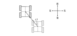
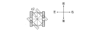
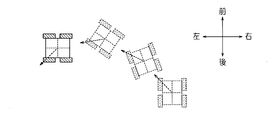
- FIG. 4A, 4B, and 4C are explanatory views showing a moving form of the omnidirectional mobile carriage 2.
- FIG. The movement form of the omnidirectional carriage 2 is three patterns of translation (FIG. 4A), rotation (FIG. 4B), and translation + rotation (FIG. 4C).
- Translational movement indicates that the omnidirectional mobile carriage 2 does not rotate (changes direction) and moves in a certain direction.
- FIG. 4A shows translational movement in the left front direction in which the angle formed with the front-rear direction is d1.
- the rotational movement indicates a movement in which the omnidirectional mobile carriage 2 rotates about a predetermined axis.
- the angle indicates the direction of movement and the speed of movement, in rotational movement, the direction of rotation and angular speed of rotation, and in translation + rotation, the angle indicates the direction of movement, speed of movement, rotational direction, and angular speed of rotation.
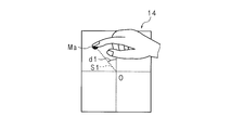
- the user slides the touching finger on the operation surface 14a and moves it to a predetermined position.
- the position after the movement is defined as a point A (first coordinate value).
- a line segment connecting the origin O and the point A (formed by the origin O and the point A) is defined as a line segment OA.
- L1 be the length of the line segment OA.
- An angle formed by the Y axis and the line segment OA is defined as d1.
- m is a coefficient.
- the value of the coefficient m may be appropriately determined according to the area of the operation surface 14a of the track pad 14 and the specifications of the omnidirectional mobile carriage 2.
- the finger using the operation may be any finger, but it is preferable to use the index finger. This is because it becomes easier to instruct the following rotational movement.
- FIG. 7A, 7B, 8A, and 8B are explanatory diagrams of the movement instruction method.
- FIG. 7A, FIG. 7B, FIG. 8A, and FIG. 8B show an instruction method for further performing rotational movement when the omnidirectional mobile carriage 2 is translated.
- the omnidirectional mobile carriage 2 performs a movement (translation movement + rotation movement) in which the translation movement and the rotation movement are combined.
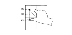
- the user touches the other part of the operation surface 14a of the track pad 14 with another finger while holding the finger used to instruct the translational movement. Let that point be B point (second coordinate value).
- the finger placed at the point B with the point A as the rotation axis is moved so as to slide on the operation surface 14a (see FIGS. 8A and 8B).
- the rotational direction of the rotational movement is determined by the moving direction when the finger is moved from point B to point C.
- the rotation direction of the omnidirectional mobile carriage 2 is also counterclockwise.
- the rotation direction of the omnidirectional mobile carriage 2 is also clockwise.
- the index finger is used when instructing the translational movement, it is preferable to use the thumb to instruct the rotational movement. Of course, other fingers may be used.
- FIG. 9A As shown in FIG. 9A, by moving the finger at point A to point A ′, the translation direction is changed from the angle d1 between the line segment OA and the Y axis to the angle d3 between the line segment OA ′ and the Y axis.
- the The translation direction is changed continuously from angles d1 to d3.
- Point B is the position where the finger moved to point C first touched the operation surface 14a when instructing rotational movement.
- Point B ′ is a point at a position corresponding to a point B moved in the same direction and distance as point A and point C. That is, the positional relationship between the points A and C and the point B and the positional relationship between the points A ′ and C ′ and the point B ′ are the same.
- FIG. 10 is an explanatory view showing a state in which the translation direction is continuously changed.
- the direction of the arrow shown in FIG. 10 is the translation direction.
- Rotation is stopped as follows.
- the finger at the point C point C ′
- the line segment AB A′B ′
- the rotational movement is stopped.
- the omnidirectional mobile trolley 2 is performing translation + rotation, only the rotation is stopped and the translation is continued.
- the finger at the point A point A ′
- the translational movement and the rotational movement are stopped, and the omnidirectional moving carriage 2 is completely stopped.
- the method of taking the angle is not limited to this.
- the position where the angle is 0 may be the X-axis direction. It is good also as taking the value of 0 degree to 360 degree
- Rotational movement command takes angular velocity as an argument.
- the unit of angular velocity is, for example, rad / s.
- the direction of rotation is represented by the sign of the value. Positive values are clockwise and negative values are counterclockwise. Not limited to this, the positive and negative meanings may be reversed.
- two arguments may be used, the first argument may be the angular velocity and the second argument may be the rotation direction.
- the translation stop command and the rotation stop command are commands for stopping the translation movement and the rotation movement, respectively, and do not take an argument.
- Commands are not limited to the above four. Other commands may be provided, or the number of commands may be reduced. For example, a command for instructing translation + rotation and a complete stop command for stopping translation and rotation may be added. On the other hand, the translation stop command and the rotation stop command may not be provided. This is because when the speed is 0 in the translation command, translation is stopped. Similarly, if the angular velocity is 0 (angular velocity magnitude 0) in the rotational movement command, the rotation is stopped. Further, the translation stop command and the rotation stop command may be integrated into one command, for example, a movement stop command.
- the movement stop command takes one argument.
- the arguments are both translation and rotation. When the argument is translation, only translation is stopped. When the argument is rotation, only rotational movement stops. When the arguments are both, both translational and rotational movements stop.
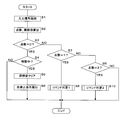
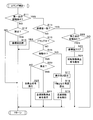
- 13 to 16 are flowcharts showing the procedure of the movement instruction process executed by the controller device 1.
- the CPU 10 of the controller device 1 processes an input signal generated when the operator operates the track pad 14 (step S1).
- the input signal processing includes A / D conversion and filtering processing.
- the CPU 10 calculates the number of input points and the coordinate value of each point (step S2).
- the number of input points is the number of points at which the track pad 14 detects input.
- the CPU 10 performs processing of the input signal and the calculation of the number of input points and the coordinate value of each point.
- the processing is performed by a signal processing driver IC (Integrated Circuit) or the like.
- the number of input points and the coordinate value of each point may be received.
- sliding the operation surface 14a without the user's finger touching the operation surface 14a of the track pad 14 being separated from the operation surface 14a is expressed as “drag”. “Dragging” means that the user keeps moving the finger.
- step S3 determines whether the number of input points is 0, that is, whether there is an input by the user (step S3). When the number of input points is 0 (YES in step S3), the CPU 10 determines whether or not the omnidirectional mobile trolley 2 is moving (step S4). Whether or not the omnidirectional mobile trolley 2 is moving may be determined from a history of issuing commands to the omnidirectional mobile trolley 2 and stored. Or you may inquire directly to the omnidirectional mobile trolley 2. If the omnidirectional mobile trolley 2 is moving (YES in step S4), the CPU 10 clears the coordinate values stored in the coordinate value storage unit 13 (step S5). CPU10 (instruction
- step S7 determines whether or not the number of input points is 1 (step S7).
- the CPU 10 (first receiving unit) performs a command determination process 1 (step S8). The CPU 10 ends the process.
- step S9 the CPU 10 determines whether or not the number of input points is 2 (step S9). When the number of input points is 2 (YES in step S9), the CPU 10 (second receiving unit) performs a command determination process 2 (step 10). The CPU 10 ends the process. If the number of input points is not two (NO in step S9), the CPU 10 ends the process. Thereafter, the CPU 10 repeatedly performs the processing shown in the flowcharts of FIGS. Since it is not assumed that the number of input points is 3 or more, if NO is determined in step S9, error processing may be performed. For example, the user may be warned that an unexpected operation has been performed by emitting a beep sound or turning on an error LED (Light Emitting Diode).
- error processing may be performed. For example, the user may be warned that an unexpected operation has been performed by emitting a beep sound or turning on an error LED (Light Emitting Diode).
- the command determination process 1 (step S8 in FIG. 13) will be described with reference to FIG.
- the first point indicates a point when there is an input from a state where nothing is input to the track pad 14. This corresponds to the point A in FIGS. 6A, 7A, and 8A described above.
- the point is referred to as a second point. This corresponds to the point B in FIGS. 7A and 8A described above.
- the command determination process 1 is a process when the number of input points is one.
- the CPU 10 determines whether or not the coordinate value of the first point is stored in the coordinate value storage unit 13 (step S11). When the first point is not stored (NO in step S11), the CPU 10 determines whether the coordinate value of the input point (hereinafter referred to as “input coordinate value”) is the origin (step S12). If it is the origin (YES in step S12), the CPU 10 stores the input coordinate value in the coordinate value storage unit 13 as the coordinate value of the first point (step S13). The CPU 10 restores the process. This is a case where the user places a finger at the origin in order to instruct translational movement. Note that an input error may be considered in the determination in step S12.
- the CPU 10 ends the process.
- step S11 When the coordinate value of the first point is stored in the coordinate value storage unit 13 (YES in step S11), the CPU 10 (first determination unit) stores the input coordinate value and the first point stored in the coordinate value storage unit 13. It is determined whether or not the coordinate values match (step S14). If the coordinate values do not match (NO in step S14), the CPU 10 determines whether or not the input point is being dragged (step S15). Whether or not the drug is being dragged is performed as follows, for example. When step S15 is reached for the first time, the input coordinate value is temporarily stored in the RAM 12. When step S15 is reached after the next time, the coordinate value stored in the RAM 12 is compared with the input coordinate value, and if they match, the number of matches is incremented.
- the number of matches is reset to 0, and the coordinate value stored in the RAM 12 is updated to the input coordinate value. It is determined that the user is dragging until the number of matches reaches a predetermined number, and when the number of matches reaches a predetermined number, it is determined that the user is not dragging. This is merely an example, and a conventional technique relating to tracking of input points on a track pad or the like may be applied.
- step S15 If it is being dragged (YES in step S15), the CPU 10 ends the process.
- step S16 determines whether or not the omnidirectional mobile carriage 2 is moving. If the omnidirectional mobile trolley 2 is moving (YES in step S16), the CPU 10 determines whether or not the input point is the origin (step S20). If the input point is the origin (YES in step S20), the CPU 10 issues a translation stop command (step S21). That is, the CPU 10 transmits a translation stop command to the omnidirectional mobile carriage 2 via the communication unit 15. The CPU 10 ends the process. If the input point is not the origin (NO in step S20), since the finger at the first point is released and only the second point is input, the CPU 10 issues a full stop command to the omnidirectional mobile carriage. 2 (Step S25).
- the CPU 10 calculates the length of the line segment connecting the input point and the origin (step S17).
- the CPU 10 calculates an angle formed by a line segment connecting the input point and the origin and the Y axis (step S18).
- the CPU 10 issues a translation command including the calculated line segment length and angle (step S19). That is, a command for translational movement is transmitted to the omnidirectional mobile carriage 2 via the communication unit 15.
- the length of the line segment indicates the translational speed (speed), and the angle indicates the translational direction. Instead of including the length of the line segment obtained as speed in the command to be transmitted, it may be a value obtained by multiplying a predetermined coefficient.
- the translation direction is as described above with reference to FIG. The speed may be determined not by the length of the line segment but by the dragged time.
- the CPU 10 determines whether or not the coordinate value of the second point is stored in the coordinate value storage unit 13 (step S22). ).
- the CPU 10 clears the coordinate value of the second point stored in the coordinate value storage unit 13 (step S23).
- the CPU 10 issues a rotational movement stop command (step S24). That is, a command to stop rotational movement is transmitted to the omnidirectional mobile carriage 2 via the communication unit 15.
- the CPU 10 ends the process.
- the coordinate value of the second point is not stored (NO in step S22)
- the CPU 10 ends the process.
- the command determination process 2 (step S10 in FIG. 13) will be described with reference to FIGS.
- the command determination process 2 is a process when the number of input points is two.
- the CPU 10 determines whether or not the coordinate value of the first point is stored in the coordinate value storage unit 13 (step S31). If the coordinate value of the first point is not stored (NO in step S31), the CPU 10 ends the process. In this case, since the operation is not assumed, error processing may be performed. An example of error processing is as described above.
- the CPU 10 determines the coordinates of the first point stored in the coordinate value storage unit 13 and the coordinate value of the first point out of the two input points. It is determined whether or not the coordinate values match (step S32).
- step S32 When the coordinate value of the first point matches the coordinate value of the first point stored in the coordinate value storage unit 13 (YES in step S32), the CPU 10 stores the coordinate value of the second point in the coordinate value storage unit 13. It is determined whether or not it is stored (step S33). When the coordinate value of the second point is not stored in the coordinate value storage unit 13 (NO in step S33), the CPU 10 stores the coordinate value of the second point in the coordinate value storage unit 13 among the two input points. (Step S34). This is a case where the user places a second finger on the operation surface 14 a of the track pad 14 in order to instruct a rotational movement. The CPU 10 ends the process.
- the CPU 10 (second determination unit) stores the input coordinate value of the second point and the coordinate value storage unit 13. It is determined whether or not the stored coordinate value of the second point matches (step S35).
- the CPU 10 ends the process. This is a state where the user has not yet instructed the rotational movement and the user has left the second finger at the initial position.
- step S35 the CPU 10 determines whether or not the second point is being dragged. Whether or not the drug is being dragged can be determined by a known technique in addition to the above-described method, and thus the description thereof is omitted. If the second point is being dragged (YES in step S36), the CPU 10 ends the process.
- step S37 the CPU 10 determines whether or not the omnidirectional mobile carriage 2 is rotating. This is performed based on a command issuance history or by making an inquiry to the omnidirectional mobile carriage 2.
- the CPU 10 stop point receiving unit
- the input coordinate value of the second point is stored in the coordinate value storage unit 13 as the coordinate value of the current second point (step S38).
- the CPU 10 (calculation unit) reads the coordinate value of the first point from the coordinate storage unit 13, and forms a line segment connecting the initial positions of the first point and the second point and a line segment connecting the first point and the current second point.
- An angle is calculated (step S39).
- the CPU 10 issues a rotational movement command including the calculated angle (step S40). That is, the CPU 10 transmits a rotational movement command to the omnidirectional mobile carriage 2 via the communication unit 15.
- the CPU 10 ends the process.
- the CPU 10 receives the coordinate value of the first point and the coordinate value of the initial position of the second point as the coordinate storage unit 13. Read from.
- the CPU 10 line segment determination unit
- the CPU 10 stores the current second point and the first point stored in the coordinate storage unit 13.
- the coordinate values of the initial positions of the two points are cleared (step S42).
- CPU10 issues a rotational movement stop command (step S43).
- the CPU 10 transmits a rotational movement stop command to the omnidirectional mobile carriage 2 via the communication unit 15.
- the CPU 10 ends the process.
- the input second point is not on a line segment connecting the first point and the initial position of the second point (NO in step S41)
- the CPU 10 ends the process.
- error processing as described above may be performed.
- the number of input points is two, which point is dragged when one point is dragged, or where each point is dragged when both points are dragged What is necessary is just to determine using a well-known technique.
- step S44 If the coordinate value of the first point does not match the coordinate value of the first point stored in the coordinate value storage unit 13 (NO in step S32), it is determined whether or not the first point is being dragged (NO in step S32). Step S44). If the first point is being dragged (YES in step S44), the CPU 10 ends the process. If the first point is not being dragged (NO in step S44), the CPU 10 determines whether or not the first point coincides with the origin (step S45). If the first point coincides with the origin (YES in step S45), the CPU 10 issues a translation stop command (step S46). That is, the CPU 10 transmits a translation stop command to the omnidirectional mobile carriage 2 via the communication unit 15. This stops only the translational movement and continues the rotational movement, so that the omnidirectional mobile carriage 2 rotates on the spot.
- the command determination process 3 is a process performed when an instruction operation for changing the translation movement direction is performed when the omnidirectional mobile carriage 2 performs translation + rotation movement.
- step S51 determines whether the coordinate value of the 2nd point is memorize
- step S51 the CPU 10 inputs the second point input as the coordinate value of the second point stored in the coordinate value storage unit 13 It is determined whether or not these coordinate values match (step S52). If the coordinate value of the second point stored in the coordinate value storage unit 13 does not match the coordinate value of the input second point (NO in step S52), the CPU 10 determines whether the second point is being dragged. Is determined (step S53).
- the CPU 10 reads out the coordinate value of the first point and the coordinate value of the initial position of the second point from the coordinate value storage unit 13 (step S54).
- the CPU 10 determines whether or not the line connecting the coordinate value of the first point and the initial position of the second point is parallel to the line connecting the current first point and the current second point (step S55). For example, the slopes of two line segments may be obtained to determine whether the values match. In order to allow a certain amount of error, not only when the values of the slopes match but also when the difference of the slope values is within a predetermined value, it may be determined as parallel.
- the CPU 10 (parallel acceptance) Part) stores the current coordinate value of the first point and the current coordinate value of the second point in the coordinate value storage unit 13 (step S56).
- the CPU 10 obtains an angle formed by a line segment connecting the current first point and the origin with the Y axis (step S57).
- the CPU 10 calculates the coordinate value of the position when the initial position of the second point is translated similarly to the first point and the second point, and the calculated coordinate value is the coordinate value of the initial position of the second point.
- the coordinate value storage unit 13 is updated (step S58).
- the CPU 10 issues a translation movement command including the calculated angle (step S59). That is, a command for translational movement is transmitted to the omnidirectional mobile carriage 2 via the communication unit 15.
- the speed since the speed is not changed, it may be set to the same value as that when the translation stop command is first issued. Alternatively, the speed may be an optional parameter, and when only the angle is given, only the translation direction may be changed without changing the speed.
- the CPU 10 ends the process.
- step S51 If the coordinate value of the second point is not stored in the coordinate value storage unit 13 (NO in step S51), the CPU 10 ends the process.
- the second point is being dragged (YES in step S53)
- the line segment connecting the coordinate value of the first point and the initial position of the second point is not parallel to the line segment connecting the current first point and the current second point (NO in step S55), the CPU 10 ends the process. To do. Since the operation is not assumed in any case except when the second point is being dragged, the error processing as described above may be performed.
- the operating device 1 can indicate the translational movement direction simply by dragging the finger placed at the origin in the direction indicating the finger. It is possible to specify the speed by the drag distance. Therefore, it is possible to instruct the omnidirectional mobile trolley 2 to move in translation by an intuitive operation.
- the operating device 1 stops the translational movement of the omnidirectional mobile carriage 2 by moving (returning) the finger used for the translational movement instruction to the origin position. Therefore, it is possible to instruct the omnidirectional mobile trolley 2 to stop the translational movement with an intuitive operation.
- the operating device 1 stops the rotational movement of the omnidirectional mobile carriage 2 by returning the finger used for the rotational movement instruction to the position where the finger is first touched.
- the rotational movement of the omnidirectional mobile trolley 2 is stopped by releasing the finger used for the rotational movement instruction from the track pad 14. Therefore, it is possible to instruct the omnidirectional mobile carriage 2 to stop the rotational movement by an intuitive operation.
- the operating device 1 changes the direction of translation by dragging the finger used for the translation movement instruction and the finger used for the rotation movement instruction. Therefore, it is possible to instruct the omnidirectional mobile trolley 2 to change the direction of translational movement with an intuitive operation.
- the operating device 1 stops the movement by releasing the finger used for the translation movement instruction from the track pad 14. Therefore, it is possible to instruct the omnidirectional mobile carriage 2 to stop by an intuitive operation.
- FIG. 17 is a diagram illustrating a configuration example of a mobile system according to the second embodiment. Since the configuration of the mobile system according to the second embodiment is substantially the same as that of the mobile system according to the first embodiment, the differences will mainly be described.
- the mobile body system includes an operating device 1 and an omnidirectional mobile carriage 2.
- the operation device 1 includes a CPU 10, a ROM 11, a RAM 12, a coordinate value storage unit 13, an operation unit 14, and a communication unit 15. Since the omnidirectional mobile trolley 2 is the same as that of Embodiment 1, description is abbreviate
- the operation device 1 includes an operation unit 14 including a display unit 141 and a contact detection unit 142 (touch panel) instead of the track pad 14 provided in the operation device 1 according to the first embodiment.
- the contact detection unit 142 is usually called a touch panel, and has a panel shape that detects the contact of a human finger, a stylus, or the like.
- the contact detection unit 142 is provided so as to cover the display surface of the display unit 141.
- the operation unit 14 has the same configuration as a so-called touch panel display. Since the contact detection unit 142 is configured to transmit light, the user can visually recognize the image displayed on the display unit 141 through the contact detection unit 142. The user can instruct the omnidirectional mobile carriage 2 to move by operating the contact detection unit 142 as in the first embodiment.
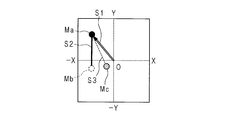
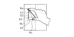
- FIG. 18 to 20 are explanatory diagrams for the movement instruction operation in the second embodiment.
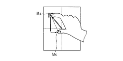
- the CPU 10 displays a marker Ma on the display unit 141 at a position corresponding to the point (first point) touched by the user's finger.
- FIG. 18 shows a translation movement instruction operation, in which the user drags the finger from the origin to the position indicated by the marker Ma.
- the CPU 10 first display processing unit
- the contact detection unit 142 detects an input and the translational movement instruction direction.
- the speed obtained from the length of the line segment S1 and the angle d1 formed by the line segment S1 and the Y axis may be displayed numerically.
- the CPU 10 When performing the rotational movement instruction, as shown in FIGS. 19A and 19B, the CPU 10 displays the markers Ma and Mb on the display unit 141 at positions corresponding to the two fingers placed by the user. Further, the CPU 10 displays a line segment S2 connecting the marker Ma and the marker Mb on the display unit 141 (see FIG. 19A). Thereby, the user can visually confirm the position of the reference line of the angle. When the user moves the second finger and gives an instruction for rotational movement, the CPU 10 erases the marker Mb and displays the marker Mc on the display unit 141 at the position of the new finger. The CPU 10 displays a line segment S3 connecting the marker Ma and the marker Mc on the display unit 141 (see FIG. 19B).
- the markers Ma and Mc allow the user to visually check the detection position of the contact detection unit 142. Further, it is possible to visually confirm the angle designated by the line segments S2 and S3. Further, since the line segment S2 is displayed, the user can easily perform an instruction to stop the rotational movement of returning the finger at the position of the marker Mc onto the line segment S2.
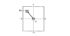
- FIG. 20 shows a state after the finger shown in FIG. 19B is dragged and a translation direction change instruction is issued.
- the CPU 10 displays markers Ma and Mc on the display unit 141. A part of the markers Ma and Mc is visible. Further, the CPU 10 displays a line segment S1 connecting the marker Ma and the origin O and a line segment S3 connecting the marker Ma and the marker Mc on the display unit 141. Further, the CPU 10 calculates a position when the marker Mb shown in FIG.
- the 19A is dragged in the same manner as the markers Ma and Mc, and displays a line segment S2 passing through the marker Ma and the calculated position on the display unit 141.
- the user can confirm the translation instruction direction of the omnidirectional mobile trolley 2 by viewing the line segment S1. Since the line segment S2 is displayed, the user can easily return the finger at the position of the marker Mc and instruct to stop the rotational movement.
- the omnidirectional mobile trolley 2 is completely stopped, only the marker Ma may be displayed at the origin O, or neither of the markers Ma and Mc may be displayed.
- the display on the display unit 141 is not limited to that described above.
- 21A and 21B are explanatory diagrams illustrating an example of a display mode of the display unit 141 during a movement instruction operation in the second embodiment.
- the display in the case of instructing translational movement + rotational movement is shown.
- the line segment S1 may be displayed on the display unit 141 even when a rotational movement instruction is given.
- the CPU 10 second display processing unit
- the operating device 1 according to the second embodiment has the following effects in addition to the effects exhibited by the operating device 1 according to the first embodiment.
- the user performs an operation using the display unit 141 and the contact detection unit 142.
- the display unit 141 displays a marker, a reference line segment, and the like together with the vertical axis and the horizontal axis. Since the user can perform an operation while confirming the marker and the reference line segment, the movement instruction operation can be performed more accurately.
- Embodiment 2 in order to continue the movement of the omnidirectional mobile trolley 2, the user needs to keep the finger touching the contact detection unit 142.
- a button for continuing the movement even when the finger is removed from the contact detection unit 142 may be provided.
- This button may be provided on the contact detection unit 142 or may be a mechanical switch other than the contact detection unit 142. Even if the user operates the button to release the finger from the contact detection unit 142, the omnidirectional mobile trolley 2 continues to move and the marker is continuously displayed on the display unit 141.
- the button operation is performed after the finger is returned to the original position, and the movement continuation is canceled.
- the movement may be continued by double-tapping the touching finger.
- the translation movement + rotation movement is instructed using two fingers, only the movement corresponding to the double-tapped finger may be continued, or both movements may be continued.
- the operation can be performed again. In the first embodiment, the same operation can be performed.
- the marker cannot be displayed on the track pad 14, it is difficult for the user to accurately place the finger at the original position. Therefore, when it is determined again whether or not the finger has been placed, the process may be performed while allowing a slight positional deviation.
- FIG. 22A, FIG. 22B, FIG. 23A, and FIG. 23B are explanatory diagrams showing an example of a display mode of the display unit 141 at the time of a movement instruction operation in the third embodiment. Since the difference from the second embodiment is the display mode of the display unit 141, this point will be mainly described and description of the other parts will be omitted.
- the marker Ma is the icon Ma of the omnidirectional mobile carriage 2.
- the icon Ma of the omnidirectional mobile carriage 2 is dragged from the origin O. Thereby, the user can visually confirm the contents of the translation movement instruction to the omnidirectional mobile carriage 2 more clearly.
- the icon Ma of the omnidirectional mobile trolley 2 is tilted and displayed by an angle proportional to the angular velocity. Thereby, the user can visually confirm the content of the rotational movement instruction to the omnidirectional mobile trolley 2 more clearly.
- the icon Ma may not be displayed tilted, but may be rotated while the rotation movement instruction is given.
- the operating device 1 according to the third embodiment has the following effects in addition to the effects exhibited by the operating device 1 according to the first and second embodiments.
- the operating device 1 according to the third embodiment by using one of the markers as an icon of the omnidirectional mobile carriage 2, the user can more clearly visually check the contents of the movement instruction.
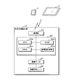
- FIG. 24 is a diagram illustrating a configuration example of a mobile system according to the fourth embodiment.
- the mobile system includes an information processing terminal 3 and an omnidirectional mobile carriage 2.
- the information processing terminal 3 has a touch panel display and a communication function.
- the information processing terminal 3 is, for example, a smartphone or a tablet computer.
- the omnidirectional mobile carriage 2 includes a moving body control unit 20, a drive motor 21, a moving chain 22, and a communication unit 23.
- the moving body control unit 20 includes a CPU 20a, a ROM 20b, a RAM 20c, a coordinate value storage unit 20d, a motor driver (not shown), and the like.
- the CPU 20a controls each part of the omnidirectional mobile trolley 2 by appropriately loading the control program stored in the ROM 20b into the RAM 20c and executing it.
- the drive motor 21 drives the moving chain 22 to run the omnidirectional mobile carriage 2.
- the communication unit 23 communicates with the information processing terminal 3. Communication between the information processing terminal 3 and the omnidirectional mobile trolley 2 may be wired or wireless.
- the communication line may be a public line or a dedicated line.
- the Internet, a packet communication network, or the like may be used as a communication line.
- short-range wireless communication may be used for communication between the information processing terminal 3 and the omnidirectional mobile trolley 2.
- an information processing terminal with a touch panel display such as a smartphone or a tablet computer can be used as a terminal for performing operation input.
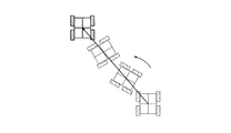
- FIG. 25 is an explanatory diagram showing an example of the movement form of the omnidirectional mobile carriage 2. As shown in FIG. 25, the center of the omnidirectional mobile trolley 2 is moved in the designated translational movement direction, while the omnidirectional mobile trolley 2 is rotationally moved around the center at the designated angular velocity.
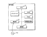
- FIG. 26 is a block diagram showing the controller device 1 according to the fifth embodiment.
- a program executed by the CPU 10 is read from a portable recording medium 16a such as a CD-ROM, a DVD disk, or a USB memory by a reading unit 16 such as a disk drive. It is good also as a structure memorize
- a semiconductor memory such as a flash memory storing the program may be mounted in the CPU 10.
- the program can be downloaded from another server computer (not shown) connected to the communication unit 15 via a communication network (not shown) such as the Internet.
- the downloaded program is stored in the ROM 11 or the coordinate value storage unit 13.
- the CPU 10 executes the program stored in the ROM 11 or the coordinate value storage unit 13 to perform the same process as the CPU 10 of the controller device 1 in the first to third embodiments.
- Operating device (movement instruction device) 10 CPU (instruction unit, first reception unit, first determination unit, second reception unit, second determination unit, stop point reception unit, calculation unit, second stop point reception unit, line segment determination unit, parallel reception unit, (First display processing unit, second display processing unit) 11 ROM 12 RAM 13 Coordinate value storage unit 14 Track pad, operation unit (coordinate input device) 141 display unit 142 contact detection unit 15 communication unit 2 omnidirectional mobile carriage 20 moving body control unit 20a CPU (instruction unit) 20b ROM 20c RAM 20d Coordinate value storage unit 21 Drive motor 22 Movement chain 23 Communication unit 3 Information processing terminal 30 Base
Landscapes
- Engineering & Computer Science (AREA)
- Physics & Mathematics (AREA)
- General Physics & Mathematics (AREA)
- Radar, Positioning & Navigation (AREA)
- Remote Sensing (AREA)
- Aviation & Aerospace Engineering (AREA)
- Automation & Control Theory (AREA)
- Computing Systems (AREA)
- Mathematical Physics (AREA)
- Theoretical Computer Science (AREA)
- User Interface Of Digital Computer (AREA)
Abstract
移動体に対する回転移動の指示が直感的に行うことが可能な移動指示装置等を提供する。移動指示装置において、座標入力装置より第1座標値の入力を受け付ける第1受付部と、第1座標値の変化の有無を定期的に判定する第1判定部と、座標入力装置から第2座標値の入力を受け付ける第2受付部と、第2座標値の変化の有無を定期的に判定する第2判定部と、第1座標値に変化がないと第1判定部が判定し、第2座標値に変化があると第2判定部が判定した後に、第2座標値に変化がないと第2判定部が判定した場合、第2座標値の停止点座標値を座標入力装置から受け付ける停止点受付部と、第1座標値及び第2座標値の初期座標値により形成される線分並びに第1座標値及び停止点座標値により形成される線分がなす角度を算出する算出部とを備え、指示部は算出した角度に基づいて移動体に回転移動指示をする。
Description
本発明は全方向に移動可能な移動体へ移動方向指示を行う移動指示装置、コンピュータプログラム、移動指示方法及び移動体システムに関する。
従来から全方向に移動可能な移動体が提案されている(特許文献1、特許文献2)。また、移動体の移動方向を指示するための操作装置として十字キーが知られている。
従来の十字キーを用いて全方向に移動可能な移動体を制御する場合、直進方向の指示は直感的でわかりやすいが、回転方向の指示操作は直感的ではなかった。
本発明は上述の状況に鑑み、移動体に対する回転移動の指示が直感的に行うことが可能な移動指示装置等を提供することを目的とする。
本発明に係る移動指示装置は、座標入力装置と、回転移動を行う移動体に移動指示をする指示部とを備える移動指示装置において、前記座標入力装置より第1座標値の入力を受け付ける第1受付部と、前記第1座標値の変化の有無を定期的に判定する第1判定部と、前記第1受付部が前記第1座標値の入力を受け付けた後に、前記座標入力装置から第2座標値の入力を受け付ける第2受付部と、前記第2座標値の変化の有無を定期的に判定する第2判定部と、前記第1座標値に変化がないと前記第1判定部が判定し、前記第2座標値に変化があると前記第2判定部が判定した後に、前記第2座標値に変化がないと前記第2判定部が判定した場合、前記第2座標値の変化後の停止点座標値を前記座標入力装置から受け付ける停止点受付部と、前記第1座標値及び第2座標値の初期座標値により形成される線分並びに前記第1座標値及び停止点座標値により形成される線分がなす角度を算出する算出部とを備え、前記指示部は算出した角度に基づいて前記移動体に回転移動指示をするようにしてあることを特徴とする。
本発明にあっては、第2座標値に変化があると判定した後に、第2座標値に変化がないと判定した場合、第2座標値の停止点座標値を座標入力装置から受け付け、第1座標値及び第2座標値の初期座標値により形成される線分並びに第1座標値及び停止点座標値により形成される線分がなす角度を算出し、算出した角度に基づいて移動体に回転移動指示をするようにしてあるので、移動体に対する回転移動の指示を、操作者は直感的に行うことが可能となる。
本発明に係る移動指示装置は、前記第1座標値に変化がないと前記第1判定部が判定し、前記第2座標値の入力がされていないと前記第2判定部が判定した場合、前記指示部は前記移動体に回転移動停止を指示するようにしてあることを特徴とする。
本発明にあっては、第1座標値に変化がないと判定し、第2座標値の入力がされていないと判定した場合、移動体に回転移動停止を指示するようにしてあるので、操作者は回転移動停止の指示を、操作者は直感的に行うことが可能となる。
本発明に係る移動指示装置は、前記第1座標値に変化がないと前記第1判定部が判定し、前記第2座標値が前記停止点座標値から更に変化したと前記第2判定部が判定した後に、前記第2座標値に変化がないと前記第2判定部が判定した場合、前記第2座標値の更に変化後の第2停止点座標値を前記座標入力装置から受け付ける第2停止点受付部と、前記第2停止点座標値が前記第1座標値及び前記第2座標値の初期座標値により形成される線分上にあるか否かを判定する線分判定部とを備え、前記第2停止点座標値が前記線分上にあると前記線分判定部が判定した場合、前記指示部は前記移動体に回転移動停止を指示するようにしてあることを特徴とする。
本発明にあっては、第1座標値に変化がないと判定し、第2座標値が前記停止点座標値から変化したと判定した後に、第2座標値に変化がないと判定した場合、第2座標値の第2停止点座標値を座標入力装置から受け付け、第2停止点座標値が第1座標値及び第2座標値の初期座標値により形成される線分上にあるか否かを判定し、第2停止点座標値が第1座標値及び第2座標値の初期座標値により形成される線分上にあると判定した場合、移動体に回転移動停止を指示するようにしてあるので、回転移動停止の指示を、操作者は直感的に行うことが可能となる。
本発明に係る移動指示装置は、前記移動体は並進移動を行うものであり、前記算出部は所定座標値及び前記第1座標値により形成される線分の方向と長さを算出し、前記指示部は算出した方向と長さに基づいて前記移動体に並進移動を指示するようにしてあることを特徴とする。
本発明にあっては、所定座標値及び第1座標値により形成される線分の方向と長さを算出し、算出した方向と長さに基づいて移動体に並進移動を指示するようにしてあるので、並進移動の方向と速力の指示を、操作者は直感的に行うことが可能となる。
本発明に係る移動指示装置は、前記第1座標値が変化したと前記第1判定部が判定した後に、前記第1座標値に変化がないと前記第1判定部が判定した場合、変化後の前記第1座標値が所定座標値と一致したとき、前記指示部は前記移動体に並進移動停止を指示するようにしてあることを特徴とする。
本発明にあっては、第1座標値に変化があると判定した後に、第1座標値に変化がないと判定した場合に、変化後の第1座標値が所定座標値に一致したとき、並進移動停止を移動体に指示するようにしてあるので、並進移動停止の指示を、操作者は直感的に行うことが可能となる。
本発明に係る移動指示装置は、前記第1判定部により前記第1座標値の入力がされていないと判定した場合、前記指示部は前記移動体に並進移動停止及び回転移動停止を指示するようにしてあることを特徴とする。
本発明にあっては、第1座標値の入力がされていないと判定した場合、移動体に並進移動停止及び回転移動停止を指示するようにしてあるので、並進移動停止命令及び回転移動停止命令を、操作者は直感的に行うことが可能となる。
本発明に係る移動指示装置は、前記第1座標値が変化したと前記第1判定部が判定し、前記第2座標値が前記停止点座標値より変化したと前記第2判定部が判定した場合に、前記座標入力装置から、前記第1座標値及び第2座標値のそれぞれの変化後の第3座標値及び第4座標値を受け付ける平行受付部と、前記第1座標値及び前記停止点座標値により形成される線分と前記第3座標値及び第4座標値により形成される線分が平行である場合、前記算出部は所定座標値及び前記第3座標値により形成される線分の方向と長さを算出し、前記指示部は算出した方向と長さに基づいて前記移動体に並進移動を指示するようにしてあることを特徴とする。
本発明にあっては、第1座標値及び第2座標値が変化したと判定した場合に、座標入力装置から、第1座標値及び第2座標値のそれぞれの変化後の3座標値及び第4座標値を受け付け、第1座標値及び停止点座標値により形成される線分と第3座標値及び第4座標値により形成される線分が平行である場合、所定座標値及び第3座標値により形成される線分の方向と長さを算出し、算出した方向と長さに基づいて移動体に並進移動を指示するようにしてあるので、並進移動の方向変更を操作者は直感的に行うことが可能となる。
本発明に係る移動指示装置は、前記座標入力装置はトラックパッドであることを特徴とする。
本発明にあっては、座標入力装置をトラックパッドとしてあるので、汎用的な部品により移動指示装置を構成することが可能となる。
本発明に係る移動指示装置は、前記座標入力装置はタッチパネルであることを特徴とする。
本発明にあっては、座標入力装置をタッチパネルとしてあるので、汎用的な部品により移動指示装置を構成することが可能となる。
本発明に係る移動指示装置は、表示部を備え、前記タッチパネルは該表示部の表示面を覆って設けられ、前記第1座標値及び第2座標値により形成される線分画像を前記表示部に表示する第1表示処理部と、前記停止点座標値を受け付けた場合、前記第2座標値の初期座標値と停止点座標値とを結ぶ弧画像を前記表示部に表示する第2表示処理部とを備えることを特徴とする。
本発明にあっては、表示部を備え、タッチパネルは表示部の表示面を覆って設けられ、第1座標値及び第2座標値により形成される線分画像を表示部に表示し、停止点座標値を受け付けた場合、第2座標値の初期座標値と停止点座標値とを結ぶ弧画像を表示部に表示するようにしてあるので、操作者は接触した位置を目視が可能であり、操作性が向上する。
本発明に係るコンピュータプログラムは、回転移動を行う移動体に対する移動指示をコンピュータに実行させるコンピュータプログラムにおいて、座標入力装置より取得した第1座標値の変化を判定し、前記第1座標値を取得した後に前記座標入力装置から取得した第2座標値の変化を判定し、前記第1座標値に変化がないと判定し、前記第2座標値が変化したことを検出した後に、前記第2座標値に変化がないと判定した場合、前記第2座標値の変化後の停止点座標値を前記座標入力装置から取得し、前記第1座標値及び第2座標値の初期座標値により形成される線分並びに前記第1座標値及び停止点座標値により形成される線分がなす角度を算出し、算出した角度に基づいて前記移動体に回転移動指示をするようにしてあることを特徴とする。
本発明に係る移動指示方法は、回転移動を行う移動体に対する移動指示を行う移動指示装置による移動指示方法において、座標入力装置より第1座標値を取得し、前記第1座標値の変化を判定し、前記第1座標値を取得した後、前記座標入力装置から第2座標値を取得し、前記第2座標値の変化を判定し、前記第1座標値に変化がないと判定し、前記第2座標値が変化したことを検出した後に、前記第2座標値に変化がないと判定した場合、前記第2座標値の変化後の停止点座標値を前記座標入力装置から取得し、前記第1座標値及び第2座標値の初期座標値により形成される線分並びに前記第1座標値及び停止点座標値により形成される線分がなす角度を算出し、算出した角度に基づいて前記移動体に回転移動指示をするようにしてあることを特徴とする。
本発明に係る移動体システムは、移動体と、上述のいずれかの移動指示装置を備えた移動体システムであって、前記移動体は前記移動指示装置からの指示に基づいて移動するようにしてあることを特徴とする。
本発明にあっては、移動体に対する回転移動の指示を、操作者は直感的に行うことが可能となる。
本発明にあっては、第2座標値に変化があると判定した後に、第2座標値に変化がないと判定した場合、第2座標値の変化後の停止点座標値を座標入力装置から受け付け、第1座標値及び第2座標値の初期座標値により形成される線分並びに第1座標値及び停止点座標値により形成される線分がなす角度を算出し、算出した角度に基づいて移動体に回転移動指示をするようにしてあるので、移動体に対する回転移動の指示を、操作者は直感的に行うことが可能となる。
以下、図面を参照して実施の形態を具体的に説明する。
実施の形態1
図1は実施の形態1に係る移動体システムの構成例を示す図である。移動体システムは操作装置1(移動指示装置)、全方向移動台車2(移動体)を含む。操作装置1は操作者が全方向移動台車2に乗りながら指示することを想定して、全方向移動台車2に備えることとしても良いし、遠隔から操作することを想定して別体としても良い。また、双方の場合を想定して、操作装置1は全方向移動台車2に着脱可能としても良い。
実施の形態1
図1は実施の形態1に係る移動体システムの構成例を示す図である。移動体システムは操作装置1(移動指示装置)、全方向移動台車2(移動体)を含む。操作装置1は操作者が全方向移動台車2に乗りながら指示することを想定して、全方向移動台車2に備えることとしても良いし、遠隔から操作することを想定して別体としても良い。また、双方の場合を想定して、操作装置1は全方向移動台車2に着脱可能としても良い。
操作装置1はCPU(Central Processing Unit)10、ROM(Read Only Memory)11、RAM(Random Access Memory)12、座標値記憶部13、トラックパッド14(座標入力装置)、通信部15を含む。CPU10はROM11に記憶されている制御プログラムを適宜RAM12にロードして実行することにより操作装置1の各部を制御する。
ROM11はEEPROM(Electrically Erasable and Programmable ROM)、フラッシュメモリ等の不揮発性メモリである。ROM11はCPU10が実行すべき制御プログラム及び各種データを予め記憶している。
RAM12はSRAM(Static RAM)、DRAM(Dynamic RAM)、フラッシュメモリ等である。RAM12はCPU10による各種プログラムの実行時に発生する種々のデータを一時的に記憶する。
座標値記憶部13はハードディスク、フラッシュディスクを用いて構成される。座標値記憶部13は全方向移動台車2の制御に必要な各種データを記憶している。なお、ROM11が記憶するプログラムは、座標値記憶部13に記憶されていてもよい。
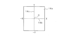
トラックパッド14は指で操作するポインティングデバイスである。二次元座標値が複数点の同時に入力が可能なものであれば良く、デジタイザやタッチパネルを用いても良い。トラックパッド14は全方向移動台車2の移動指示入力を受け付ける。
全方向移動台車2は移動体制御部20、駆動モータ21、移動用チェーン22、通信部23を含む。移動体制御部20はCPU、ROM、RAM、モータドライバ等を含む。移動体制御部20のCPUはROMに記憶されている制御プログラムを適宜RAMにロードして実行することにより全方向移動台車2の各部を制御する。
駆動モータ21は移動用チェーン22を駆動し全方向移動台車2を走行させる。通信部23は操作装置1との通信を行う。操作装置1と全方向移動台車2との通信は有線でも、無線でも良い。通信回線は公衆回線でも専用回線でも良い。インターネット、パケット通信網などを通信回線としても良い。
図2は実施の形態1に係る全方向移動台車2の斜視図、図3は複数のローラを除く全方向移動台車2の平面図である。以下の説明では図において矢印で示す前後、左右、上下を使用する。全方向移動台車2は走行面P上を多方向に移動可能な多方向移動体モジュールである。基体30は、チェーン51R,51L,56R,56L等が取り付けられる移動体モジュール本体部分である。走行面Pは、全方向移動台車2が移動する面であることから移動面Pと表記してもよく、走行面と移動面の意味は同等である。以下の説明では「走行面P」を用いる。チェーン51R,51L,56R,56Lが図1に示した移動用チェーン22に対応している。
走行面Pに沿って移動する基体30には、前部左右に相互に独立して駆動される一対のチェーン(帯状駆動体)51R、51Lが設けてあり、後部左右に相互に独立して駆動される一対のチェーン56R、56Lが設けてある。チェーン51R,51L,56R,56Lは、循環経路に沿って正逆両方向に駆動可能である。正方向の駆動とは、チェーンの走行面側部分(接地面側部分)である下側部分を後ろ向きに駆動するとともにチェーンの上側部分を前向きに駆動するようにチェーン全体を駆動することをいい、逆方向の駆動とは、正方向に対して逆向きにチェーン全体を駆動することをいう。
上側又は下側のチェーン51R,51L,56R,56Lの駆動方向D1に沿って、例えば等間隔で、チェーン51R,51L,56R,56Lにローラ(回転体)54R,54L,59R,59Lが配列されている。ローラ54R,54L,59R,59Lは、チェーン51R,51L,56R,56Lの駆動方向D1に対して斜交する回転軸541R,541L,591R,591Lがそれぞれ平行となるように軸着された状態で走行面Pに外周面542R,542L,592R,592Lをそれぞれ接触させる。一対のチェーン51R,51L及びこれらに固定設置されたローラ54R,54Lは一対の駆動体ユニット50を構成し、一対のチェーン56R,56L及びこれらに固定設置されたローラ59R,59Lは一対の駆動体ユニット55を構成する。駆動体ユニット50及び55は、駆動方向D1に配列されており更に一対をなす。
複数のローラ54R,54L,59R,59Lのそれぞれの外周面542R,542L,592R,592Lを走行面Pに接触させた状態で基体30の荷重を各ローラ54R,54L,59R,59Lで分担して支持する。基体30の荷重に応じて走行面Pから各ローラ54R,54L,59R,59Lに作用する力に対する反作用力の合力方向に基体30の駆動力を発生させるため、各ローラ54R,54L,59R,59Lの表面の摩耗を回避し、走行面Pに沿って多方向に円滑且つ自在に基体30を移動させることができる。
また、図3に示すように、動力伝達用回転体である駆動スプロケット502Lの駆動軸402Lと動力伝達用回転体である従動スプロケット503Rの従動軸404Rは、相互に繋がっていない。従動スプロケット503Lの従動軸404Lと駆動スプロケット502Rの駆動軸402Rも、相互に繋がっていない。駆動スプロケット502L及び従動スプロケット503Lは前後方向に沿って並列配置されている。駆動モータ401Lは、駆動スプロケット502Lを駆動し、駆動スプロケット502Lに対して従動スプロケット503Lを従動させる。駆動スプロケット502R及び従動スプロケット503Rは前後方向に沿って並列配置されている。駆動モータ401Rは、駆動スプロケット502Rを駆動し、駆動スプロケット502Rに対して従動スプロケット503Rを従動させる。
動力伝達用回転体である駆動スプロケット507Lの駆動軸407Lと動力伝達用回転体である従動スプロケット508Rの従動軸409Rは、相互に繋がっていない。従動スプロケット508Lの従動軸409Lと駆動スプロケット507Rの駆動軸407Rも、相互に繋がっていない。駆動スプロケット507L及び従動スプロケット508Lは前後方向に沿って並列配置されている。駆動モータ406Lは、駆動スプロケット507Lを駆動し、駆動スプロケット507Lに対して従動スプロケット508Lを従動させる。駆動スプロケット507R及び従動スプロケット508Rは前後方向に沿って並列配置されている。駆動モータ406Rは、駆動スプロケット507Rを駆動し、駆動スプロケット507Rに対して従動スプロケット508Rを従動させる。
すなわち、前後方向に配置されたチェーン51L,51R,56L,56Rは相互に独立して駆動される。また、全方向移動台車2の重量バランスをとることとモータの設置スペースを確保することとの両方を実現するために、図3に示すように、各駆動体ユニット50、55のそれぞれについて前後に一つずつ駆動モータ401L、401R、406L、406Rが配置されている。駆動モータ401L、401R、406L、406Rが図1に示した駆動モータ21に対応している。
また、全方向移動台車2は、一対のチェーン51R,51Lや一対のチェーン56R,56Lのそれぞれの駆動方向D1が、相互に平行であることにより、一対のチェーン51R,51Lや一対のチェーン56R,56Lの回転駆動方向と駆動速度Vとの2つのパラメータを制御して基体30の移動速度及びその方向を調整することにより、基体30を走行面Pに沿って多方向に円滑且つ自在に移動可能となっている。
次に全方向移動台車2の移動形態について説明する。図4A,図4B及び図4Cは全方向移動台車2の移動形態を示す説明図である。全方向移動台車2の移動形態は並進移動(図4A)、回転移動(図4B)、並進移動+回転移動(図4C)の3パターンである。並進移動は全方向移動台車2が回転をせず(向きを変えず)一定方向に平行移動することを示す。図4Aでは前後方向となす角がd1となる左斜め前方向への並進移動を示している。回転移動とは所定の軸を中心に全方向移動台車2が回転する移動を示す。回転移動のみ場合はその場で回転することとなるので、全方向移動台車2の姿勢は変わるものの位置は変化しない。図4Bに示すのは左回りに角速度d2で回転する移動を示す。並進移動+回転移動は並進移動と回転移動を合成した移動である。所定の軸を中心に所定の角速度で回転しつつ、一定方向に平行移動するという移動である。図4Cに示すのが一例である。
上記の各移動形態を全方向移動台車2に行わせるには、それぞれ次に示す値を指示する必要がある。並進移動では移動方向を示す角度及び移動の速力、回転移動では回転方向及び回転の角速度、並進移動+回転移動では、移動方向を示す角度、移動の速力、回転方向及び回転の角速度である。
本実施の形態における移動指示方法について説明する。
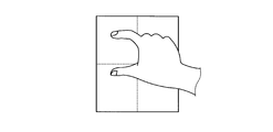
図5はトラックパッド14の操作面14aの一例を示す説明図である。トラックパッド14の操作面14aに横軸14b、縦軸14cの軸線が示されている。横軸14bをX軸、縦軸14cをY軸とする。X軸とY軸との交点を原点O(所定座標)とする。図6A及び図6Bは移動指示方法についての説明図である。図6A及び図6Bには並進移動を指示する場合の操作方法を示す。ユーザは操作に用いる指で操作面14aの原点Oを触れる。次にユーザは触れている指を操作面14a上で滑らし、所定の位置に移動する。移動した後の位置を点A(第1座標値)とする。原点Oと点Aを結ぶ線分(原点O及び点Aにより形成される)を線分OAとする。線分OAの長さをL1とする。Y軸と線分OAとがなす角度をd1とする。この場合、操作装置1は角度d1の方向に速さv1(=m×L1)で移動するよう全方向移動台車2に対して命令を送信する。ここでmは係数である。係数mの値はトラックパッド14の操作面14aの面積、全方向移動台車2の仕様に合わせて適宜定めれば良い。操作を用いる指は任意の指で良いが、人差し指を用いるのが好適である。以下に示す回転移動の指示が行い易くなるからである。
図5はトラックパッド14の操作面14aの一例を示す説明図である。トラックパッド14の操作面14aに横軸14b、縦軸14cの軸線が示されている。横軸14bをX軸、縦軸14cをY軸とする。X軸とY軸との交点を原点O(所定座標)とする。図6A及び図6Bは移動指示方法についての説明図である。図6A及び図6Bには並進移動を指示する場合の操作方法を示す。ユーザは操作に用いる指で操作面14aの原点Oを触れる。次にユーザは触れている指を操作面14a上で滑らし、所定の位置に移動する。移動した後の位置を点A(第1座標値)とする。原点Oと点Aを結ぶ線分(原点O及び点Aにより形成される)を線分OAとする。線分OAの長さをL1とする。Y軸と線分OAとがなす角度をd1とする。この場合、操作装置1は角度d1の方向に速さv1(=m×L1)で移動するよう全方向移動台車2に対して命令を送信する。ここでmは係数である。係数mの値はトラックパッド14の操作面14aの面積、全方向移動台車2の仕様に合わせて適宜定めれば良い。操作を用いる指は任意の指で良いが、人差し指を用いるのが好適である。以下に示す回転移動の指示が行い易くなるからである。
図7A,図7B,図8A及び図8Bは移動指示方法についての説明図である。図7A,図7B,図8A及び図8Bは全方向移動台車2が並進移動している場合に、回転移動を更に行わせるための指示方法を示している。すなわち、全方向移動台車2は並進移動と回転移動とが合成された移動(並進移動+回転移動)を行う。
ユーザは並進移動を指示するのに用いた指を保持しつつ、他の指でトラックパッド14の操作面14aの他の部分を触れる。その点をB点とする(第2座標値)。次にA点を回転軸としてB点に置いている指を、操作面14a上を滑らすようにして移動させる(図8A及び図8B参照)。移動した後の点をC(停止点座標値)とする。この場合、点Aと点Bを結ぶ線分AB及び点Aと点Cとを結ぶ線分ACがなす角度をd2とする。このとき全方向移動台車2は並進移動をしつつ、回転移動を行う。回転移動の角速度の大きさは角度d2に比例するものとする。角速度v2を、v2(=n×d2)とする。ここでnは係数である。係数nの値はトラックパッド14の操作面14aの面積、全方向移動台車2の仕様に合わせて適宜定めれば良い。回転移動の回転方向は点Bから点Cへ指を動かした際の移動方向により定める。図8A及び図8Bに示した例では反時計回りに指を動かしているので、全方向移動台車2の回転方向も反時計回りとなる。点Bにある指を時計回りに移動すると、全方向移動台車2の回転方向も時計回りとなる。なお、並進移動を指示する際し人差し指を用いた場合、回転移動を指示するのは親指を用いるのが好適である。もちろん、他の指を用いても良い。
ユーザは並進移動を指示するのに用いた指を保持しつつ、他の指でトラックパッド14の操作面14aの他の部分を触れる。その点をB点とする(第2座標値)。次にA点を回転軸としてB点に置いている指を、操作面14a上を滑らすようにして移動させる(図8A及び図8B参照)。移動した後の点をC(停止点座標値)とする。この場合、点Aと点Bを結ぶ線分AB及び点Aと点Cとを結ぶ線分ACがなす角度をd2とする。このとき全方向移動台車2は並進移動をしつつ、回転移動を行う。回転移動の角速度の大きさは角度d2に比例するものとする。角速度v2を、v2(=n×d2)とする。ここでnは係数である。係数nの値はトラックパッド14の操作面14aの面積、全方向移動台車2の仕様に合わせて適宜定めれば良い。回転移動の回転方向は点Bから点Cへ指を動かした際の移動方向により定める。図8A及び図8Bに示した例では反時計回りに指を動かしているので、全方向移動台車2の回転方向も反時計回りとなる。点Bにある指を時計回りに移動すると、全方向移動台車2の回転方向も時計回りとなる。なお、並進移動を指示する際し人差し指を用いた場合、回転移動を指示するのは親指を用いるのが好適である。もちろん、他の指を用いても良い。
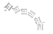
図9A及び図9Bは移動指示方法についての説明図である。図7A,図7B,図8A及び図8Bで示している操作により並進移動+回転移動している全方向移動台車2の並進する方向を変化させるための操作を、図9A及び図9Bは示している。図8Bの状態から2本の指を互いの位置関係を変えずに、操作面14a上を滑らして移動する。移動後の指の位置を点A’(第3座標値)、点C’(第4座標値)とする。点A、点Cはそれぞれ移動する前の指の位置である。全方向移動台車2が並進する方向は図6Aに示すように線分OAとY軸とのなす角度で指示している。図9Aで示すように点Aにある指を点A’に移動させたことにより、並進方向は線分OAとY軸となす角度d1から線分OA’とY軸となす角度d3に変更される。並進方向の変更は角度d1からd3に連続的に行われる。点Bは回転移動を指示する際、点Cに移動した指が最初に操作面14aに触れた位置である。点B’は点Bを点A、点Cと同様な方向、距離移動した場合に対応する位置の点である。すなわち、点A及び点Cと点Bとの位置関係並びに点A’及び点C’と点B’との位置関係は同様となっている。図10は並進方向が連続的に変更される様子を示した説明図である。図10に示す矢印の方向が並進方向である。並進方向が角度d1からd3へ連続的に変更されている様子を示している。
並進移動の停止は次のようにして行う。点A(点A’)にある指を原点に戻すと並進移動を停止する。並進移動のみをしていた場合、全方向移動台車2は完全に停止した状態となる。全方向移動台車2が並進移動+回転移動をしている場合、並進移動のみを停止し、回転移動は継続する。全方向移動台車2はその場で回転移動することとなる。
回転移動の停止は次のように行う。点C(点C’)にある指を線分AB(A’B’)上(第2停止点座標値)へ移動すると回転移動を停止する。全方向移動台車2が並進移動+回転移動をしている場合、回転移動のみを停止し、並進移動は継続する。点A(点A’)にある指を離すと、並進移動及び回転移動を停止し、全方向移動台車2は完全に停止した状態となる。
全方向移動台車2に対する指示操作は上述した操作に限らず、以下の様な指示操作を採用しても良い。並進移動の速力は線分OAの長さで定めたが、指が原点Oから点Aまで動くまでの時間を計測し、計測した時間に比例する値を速力としても良い。点A(点A’)にある指を離した場合に、並進移動及び回転移動を停止するのではなく、並進移動のみを停止し、回転移動は継続することとしても良い。点C(点C’)にある指を離すことで回転移動を停止しても良い。
並進移動を指示している場合において、点Aに置いている指を原点から遠ざけることにより並進移動の速さを増加させ、原点Oに近づけることにより並進移動の速さを減少させても良い。回転移動を指示している場合において、点Cに置いている指を点Bに近づける方向に動かすと回転速度を減少させ、点Bから遠ざける方向に動かすと回転速度を増加させても良い。
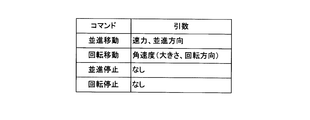
上述した移動指示方法に応じて操作装置1から全方向移動台車2へ送信するコマンド(命令)体系を構成する。図11は全方向移動台車2のコマンド体系の一例を示す一覧表である。コマンドと引数を示している。コマンドは並進移動コマンド、回転移動コマンド、並進停止コマンド、回転停止コマンドの4種類である。並進移動コマンドは引数として速力と並進方向を取る。速力は並進する速力(速度の大きさ)である。速力の単位は例えばm/sである。並進方向は全方向移動台車2の前後方向をY軸とした時に並進方向を示すベクトルとY軸とがなす角度を指定する。角度の値に正負を設け、右前方、右後方に進む場合を正の値、左前方、左後方に進む場合は負の値とする。図12は並進方向を示す角度の例を示す説明図である。全方向移動台車2において所定位置を原点として前後方向をY軸、左右方向X軸としている。ここに示す座標系が図5に示すトラックパッド14の操作面14aの座標系と対応付けられている。図12に示すように、全方向移動台車2を右前方45度の方向に並進移動させる場合は、並進方向の引数として+45度を指定する。全方向移動台車2を左後方30度の方向に並進移動させる場合は、並進方向の引数として-120度を指定する。角度の取り方はこれに限られない。角度0とする位置をX軸方向としても良い。角度の値として負の値を設けず、0度から360度の値を取ることとしても良い。
回転移動コマンドは引数として角速度を取る。角速度の単位は例えばrad/sである。回転方向は値の正負で表す。正の値は時計回り、負の値は反時計回りとする。これに限らず、正負の意味を逆にしても良い。また、引数を2つにして、第一引数を角速度の大きさ、第二引数を回転方向としても良い。並進停止コマンド、回転停止コマンドはそれぞれ並進移動、回転移動を停止するコマンドであり、引数は取らない。
コマンドは上述の4つに限られるものではない。他のコマンドを設けても良いし、コマンドを減らしても良い。例えば、並進移動+回転移動を指示するコマンド、並進移動及び回転停止をする完全停止コマンドを追加しても良い。一方、並進停止コマンド、回転停止コマンドは設けなくても良い。並進移動コマンドにおいて速力0とすると、並進停止となるからである。同様に回転移動コマンドにおいて角速度0(角速度の大きさ0)とすると回転停止となるからである。また、並進停止コマンドと回転停止コマンドとを統合して1つのコマンド、例えば移動停止コマンドとしても良い。移動停止コマンドは引数を1つ取る。引数は並進、回転、両方である。引数が並進のときは並進移動のみが停止する。引数が回転のときは回転移動のみが停止する。引数が両方のときは、並進移動及び回転移動の両方の移動が停止する。
次に操作装置1における情報処理について説明する。図13から図16は操作装置1で実行される移動指示処理の手順を示すフローチャートである。操作装置1のCPU10は、操作者がトラックパッド14を操作することにより発生する入力信号の処理を行う(ステップS1)。入力信号の処理とはA/D変換やフィルタリング処理などである。CPU10は入力点数及び各点の座標値を算出する(ステップS2)。入力点数とはトラックパッド14が入力を検知した点の数である。なお、ここでは入力信号の処理並びに入力点数及び各点の座標値の算出をCPU10が行うものとしたが、信号処理用のドライバIC(Integrated Circuit)等により処理を行わせ、CPU10はドライバICから入力点数及び各点の座標値を受け取ることとしても良い。なお、以下の説明において、ユーザがトラックパッド14の操作面14aに触れている指を操作面14aから離すことなく、操作面14aを滑らすことを「ドラッグ」と表現する。「ドラッグ中」とはユーザが指を動かし続けているという意味である。
CPU10は入力点数が0であるか、すなわち、ユーザによる入力があるか否かを判定する(ステップS3)。入力点数が0の場合(ステップS3でYES)、CPU10は全方向移動台車2が移動中であるか否かを判定する(ステップS4)。全方向移動台車2が移動中であるか否かの判定は、全方向移動台車2への命令の発行履歴を記憶しておき、履歴より判定すれば良い。または全方向移動台車2へ直接問い合わせても良い。全方向移動台車2が移動中である場合(ステップS4でYES)、CPU10は座標値記憶部13に記憶している座標値をクリアする(ステップS5)。CPU10(指示部)は全停止命令を全方向移動台車2に対して発行する(ステップS6)。ここで「全停止」とは並進移動及び回転移動を共に停止することを意味している。全方向移動台車2が移動中でない場合(ステップS4でNO)、CPU10は、ステップS5,S6の処理をスキップして処理を終了する。
入力点数が0でない場合(ステップS3でNO)、CPU10は入力点数が1点であるか否か判定する(ステップS7)。入力点数が1点の場合(ステップS7でYES)、CPU10(第1受付部)はコマンド判定処理1を行う(ステップS8)。CPU10は処理を終了する。
入力点数が1点ではない場合(ステップS7でNO)、CPU10は入力点数が2点であるか否か判定する(ステップS9)。入力点数が2点である場合(ステップS9でYES)、CPU10(第2受付部)はコマンド判定処理2を行う(ステップ10)。CPU10は処理を終了する。入力点数が2点ではない場合(ステップS9でNO)、CPU10は処理を終了する。以後、CPU10は図13から図16のフローチャートに示した処理を繰り返し行う。なお、入力点数が3点以上は想定していないため、ステップS9でNOと判定された場合は、エラー処理を行なっても良い。例えば、ビープ音を発したり、エラー用のLED(Light Emitting Diode)を点灯したりするなどにより、想定しない操作がされたことをユーザに警告しても良い。
図14を参照しつつ、コマンド判定処理1(図13のステップS8)について説明する。以下の記載では第一点、第二点という語を用いるので、語の示す意味を説明する。第一点とはトラックパッド14に何も入力されていない状態から一点の入力があった場合、その点のことを示す。上述した図6A,図7A及び図8Aにおける点Aに相当する。第一点が入力されている状態で新たな点が入力された場合、その点を第二点と言う。上述した図7A及び図8Aにおける点Bに相当する。
コマンド判定処理1は入力点数が1つの場合の処理である。CPU10は第一点の座標値が座標値記憶部13に記憶されているか否か判定する(ステップS11)。第一点が記憶されていない場合(ステップS11でNO)、CPU10は入力された点の座標値(以下、「入力座標値」と記す。)が原点であるか判定する(ステップS12)。原点である場合(ステップS12でYES)、CPU10は入力座標値を第一点の座標値として座標値記憶部13に記憶する(ステップS13)。CPU10は処理を元に戻す。これは、並進移動を指示するためにユーザが原点に指を置いた場合である。なお、ステップS12での判定では入力誤差を考慮しても良い。例えば、入力座標値が原点座標に一致しなくても、入力された点と原点とのユークリッド距離が所定の値以下の場合は、原点にあるものとして扱っても良い。原点でない場合(ステップS12でNO)、CPU10は処理を終了する。
第一点の座標値が座標値記憶部13に記憶してある場合(ステップS11でYES)、CPU10(第1判定部)は入力座標値と座標値記憶部13に記憶されている第一点の座標値とが一致するかを判定する(ステップS14)。座標値が一致していない場合(ステップS14でNO)、CPU10は入力された点がドラッグ中であるか否かを判定する(ステップS15)。ドラッグ中であるか否かは例えば次のように行う。最初にステップS15に達した時に入力座標値をRAM12に一時的に記憶しておく。次回以降ステップS15に達したときは、RAM12に記憶した座標値と入力座標値を比較し、一致していれば一致回数をインクリメントする。一致してなければ一致回数を0にリセットし、RAM12に記憶する座標値を入力座標値に更新する。一致回数が所定の回数に達するまではドラッグ中と判定し、一致回数が所定の回数に達したら、ドラッグ中でないと判定する。これはあくまでも一例であり、トラックパッド等における入力点の追跡に関する従来技術を適用しても良い。
ドラッグ中である場合(ステップS15でYES)、CPU10は処理を終了する。ドラッグ中でない場合(ステップS15でNO)、CPU10は全方向移動台車2が移動中であるか否かを判定する(ステップS16)。全方向移動台車2が移動中である場合(ステップS16でYES)、CPU10は入力された点が原点であるか否かを判定する(ステップS20)。入力された点が原点である場合(ステップS20でYES)、CPU10は並進移動停止命令を発行する(ステップS21)。すなわち、CPU10は並進移動停止のコマンドを、通信部15を介して全方向移動台車2に対して送信する。CPU10は処理を終了する。入力された点が原点ではない場合(ステップS20でNO)、第一点においていた指が離され、第二点のみが入力されている場合であるので、CPU10は全停止命令を全方向移動台車2に対して発行する(ステップS25)。
全方向移動台車2が移動中でない場合(ステップS16でNO)、CPU10は入力された点と原点とを結ぶ線分の長さを算出する(ステップS17)。CPU10は入力された点と原点とを結ぶ線分とY軸とがなす角度を算出する(ステップS18)。CPU10は算出した線分の長さ、角度を含む並進移動命令を発行する(ステップS19)。すなわち、並進移動のコマンドを、通信部15を介して全方向移動台車2に対して送信する。線分の長さは並進移動の速力(速さ)を、角度は並進方向を示す。送信するコマンドに速力として求めた線分の長さをそのまま含めるのではなく、所定の係数を乗じた値としても良い。並進方向は図12を用いて上述したとおりである。なお、速力を線分の長さではなく、ドラッグした時間により定めることとしても良い。
入力座標値と第一点の座標値とが一致する場合(ステップS14でYES)、CPU10は第二点の座標値が座標値記憶部13に記憶してあるか否かを判定する(ステップS22)。第二点の座標値が記憶されている場合(ステップS22でYES)、CPU10は座標値記憶部13に記憶してある第二点の座標値をクリアする(ステップS23)。CPU10は回転移動停止命令を発行する(ステップS24)。すなわち、回転移動停止のコマンドを、通信部15を介して全方向移動台車2に対して送信する。CPU10は処理を終了する。第二点の座標値が記憶されていない場合(ステップS22でNO)、CPU10は処理を終了する。
図15及び図16を参照しつつ、コマンド判定処理2(図13のステップS10)について説明する。コマンド判定処理2は入力点数が2つの場合の処理である。CPU10は第一点の座標値が座標値記憶部13に記憶されているか否かを判定する(ステップS31)。第一点の座標値が記憶されてない場合(ステップS31でNO)、CPU10は処理を終了する。この場合は想定しない操作であるため、エラー処理を行なっても良い。エラー処理の例は上述したとおりである。第一点の座標が記憶されている場合(ステップS31でYES)、CPU10は入力されている2点のうち、第一点の座標値と座標値記憶部13に記憶されている第一点の座標値とが一致するか否かを判定する(ステップS32)。第一点の座標値と座標値記憶部13に記憶されている第一点の座標値とが一致する場合(ステップS32でYES)、CPU10は第二点の座標値が座標値記憶部13に記憶されているか否かを判定する(ステップS33)。第二点の座標値が座標値記憶部13に記憶されていない場合(ステップS33でNO)、CPU10は入力されている2点のうち、第二点の座標値を座標値記憶部13に記憶する(ステップS34)。これは、回転移動を指示するためにユーザが二本目の指をトラックパッド14の操作面14aに置いた場合である。CPU10は処理を終了する。
第二点の座標値が座標値記憶部13に記憶されている場合(ステップS33でYES)、CPU10(第2判定部)は入力されている第二点の座標値と座標値記憶部13に記憶されている第二点の座標値とが一致するか否かを判定する(ステップS35)。入力されている第二点の座標値と座標値記憶部13に記憶されている第二点の座標値とが一致している場合、すなわち第二点の座標に変化がないと判定した場合(ステップS35でYES)、CPU10は処理を終了する。これは、まだ回転移動の指示をしておらず、ユーザは二本目の指を初期位置に置いたままの状態である。入力されている第二点の座標値と座標値記憶部13に記憶されている第二点の座標値とが一致しない場合、すなわち、第二点の座標に変化があると判定した場合(ステップS35でNO)、CPU10は第二点がドラッグ中であるか否かを判定する(ステップS36)。ドラッグ中であるか否かは上述した方法のほか、公知の技術で可能であるので、説明を省略する。第二点がドラッグ中である場合(ステップS36でYES)、CPU10は処理を終了する。
第二点がドラッグ中でない場合(ステップS36でNO)、CPU10は全方向移動台車2が回転移動中であるか否かを判定する(ステップS37)。これはコマンドの発行履歴により行うか、全方向移動台車2に問い合わせを行うなどをして行う。全方向移動台車2が回転移動中でない場合(ステップS37でNO)、CPU10(停止点受付部)はすでに記憶されている第二点の座標値を第二点の初期位置座標値(第2座標の初期座標値)として記憶し、入力された第二点の座標値を現在の第二点の座標値として座標値記憶部13に記憶する(ステップS38)。CPU10(算出部)は第一点の座標値を座標記憶部13から読み出し、第一点及び第二点の初期位置を結ぶ線分並びに第一点及び現在の第二点を結ぶ線分がなす角度を算出する(ステップS39)。CPU10は算出した角度を含む回転移動命令を発行する(ステップS40)。すなわち、CPU10は回転移動のコマンドを、通信部15を介して全方向移動台車2に対して送信する。CPU10は処理を終了する。
全方向移動台車2が回転移動中である場合(ステップS37でYES)、CPU10(第2停止点受付部)は第一点の座標値及び第二点の初期位置の座標値を座標記憶部13から読み出す。CPU10(線分判定部)は入力された第二点が第一点及び第二点の初期位置を結ぶ線分上にあるか否かを判定する(ステップS41)。入力された第二点が第一点及び第二点の初期位置を結ぶ線分上にある場合(ステップS41でYES)、CPU10は座標記憶部13に記憶されている現在の第二点及び第二点の初期位置の座標値をクリアする(ステップS42)。CPU10は回転移動停止命令を発行する(ステップS43)。すなわち、CPU10は回転移動停止のコマンドを、通信部15を介して全方向移動台車2に対して送信する。CPU10は処理を終了する。入力された第二点が第一点及び第二点の初期位置を結ぶ線分上にない場合(ステップS41でNO)、CPU10は処理を終了する。この場合は、想定しない操作であるため、上述したようなエラー処理を行なっても良い。
なお、入力点数が2点である場合において、一方の点がドラッグされた場合にどちらの点がドラッグされているのか、両方の点がドラッグされた場合に各点がどのような位置にドラッグされたかについては、公知の技術を用いて判定すれば良い。
なお、入力点数が2点である場合において、一方の点がドラッグされた場合にどちらの点がドラッグされているのか、両方の点がドラッグされた場合に各点がどのような位置にドラッグされたかについては、公知の技術を用いて判定すれば良い。
第一点の座標値と座標値記憶部13に記憶されている第一点の座標値とが一致しない場合(ステップS32でNO)、第一点がドラッグ中であるか否かを判定する(ステップS44)。第一点がドラッグ中である場合(ステップS44でYES)、CPU10は処理を終了する。第一点がドラッグ中でない場合(ステップS44でNO)、CPU10は第一点が原点と一致するか否かを判定する(ステップS45)。第一点が原点と一致する場合(ステップS45でYES)、CPU10は並進移動停止命令を発行する(ステップS46)。すなわち、CPU10は並進移動停止のコマンドを、通信部15を介して全方向移動台車2に対して送信する。これは、並進移動のみを停止し回転移動は継続するので、全方向移動台車2はその場で回転することとなる。
第一点が原点と一致しない場合(ステップS45でNO)、CPU10はコマンド判定処理3を行う(ステップS47)。図16を参照しつつ、コマンド判定処理3について説明する。コマンド判定処理3は、全方向移動台車2が並進移動+回転移動をしている場合に、並進移動方向を変える指示操作をしたときの処理である。
CPU10は座標値記憶部13に第二点の座標値が記憶されているか否かを判定する(ステップS51)。第二点の座標値が座標値記憶部13に記憶されている場合(ステップS51でYES)、CPU10は座標値記憶部13に記憶されている第二点の座標値と入力された第二点の座標値とが一致するか否かを判定する(ステップS52)。座標値記憶部13に記憶されている第二点の座標値と入力された第二点の座標値が一致しない場合(ステップS52でNO)、CPU10は第二点がドラッグ中であるか否かを判定する(ステップS53)。第二点がドラッグ中でない場合(ステップS53でNO)、CPU10は座標値記憶部13から第一点の座標値、第二点の初期位置の座標値を読み出す(ステップS54)。CPU10は第一点の座標値及び第二点の初期位置を結ぶ線分と現在の第一点及び現在の第二点を結ぶ線分とが平行であるかを判定する(ステップS55)。例えば、2つの線分の傾きを求めて値が一致するか否かを判定すれば良い。ある程度の誤差を許容するために、傾きの値が一致する場合のみならず、傾きの値の差分が所定値以内である場合も平行と判定することとしても良い。
第一点の座標値及び第二点の初期位置を結ぶ線分と現在の第一点及び現在の第二点を結ぶ線分とが平行である場合(ステップS55でYES)、CPU10(平行受付部)は現在の第一点の座標値、現在の第二点の座標値を座標値記憶部13に記憶する(ステップS56)。CPU10は現在の第一点と原点とを結ぶ線分がY軸となす角度を求める(ステップS57)。第二点の初期位置が第一点及び第二点と同様に平行移動した場合の位置の座標値を、CPU10は算出し、算出した座標値を第二点の初期位置の座標値であるとして、座標値記憶部13を更新する(ステップS58)。CPU10は算出した角度を含む並進移動命令を発行する(ステップS59)。すなわち、並進移動のコマンドを、通信部15を介して全方向移動台車2に対して送信する。この場合、速力は変化させないので、最初に並進移動停命令を発行した時の値と同一の値とすれば良い。または速力はオプショナルパラメータとし、角度のみを与えた場合は、速力を変化させずに並進方向のみを変化させることとしても良い。CPU10は処理を終了する。
第二点の座標値が座標値記憶部13に記憶されていない場合(ステップS51でNO)、CPU10は処理を終了する。座標値記憶部13に記憶されている第二点の座標値と入力された第二点の座標値が一致する場合(ステップS52でYES)、CPU10は処理を終了する。第二点がドラッグ中である場合(ステップS53でYES)、CPU10は処理を終了する。第一点の座標値及び第二点の初期位置を結ぶ線分と現在の第一点及び現在の第二点を結ぶ線分とが平行でない場合(ステップS55でNO)、CPU10は処理を終了する。なお、第二点がドラッグ中である場合を除く、いずれの場合も想定しない操作であるため、上述したようなエラー処理を行なっても良い。
実施の形態1に係る操作装置1は原点に置いた指を指示する方向にドラッグするだけで並進移動方向を指示することが可能である。ドラッグした距離により速力を指定することが可能である。よって、直感的な操作で全方向移動台車2に対して、並進移動を指示することが可能である。
実施の形態1に係る操作装置1は、並進移動の指示に用いた指以外の指をトラックパッド14上で、並進移動の指示に用いた指を軸として回転させるようにドラッグするだけで、回転移動の指示が可能である。回転した角度により回転移動の速力(速さ)を指定する。よって、直感的な操作で全方向移動台車2に対して、回転移動を指示することが可能である。
実施の形態1に係る操作装置1は、並進移動の指示に用いた指を原点位置に移動させる(戻す)ことにより、全方向移動台車2の並進移動を停止させる。よって、直感的な操作で全方向移動台車2に対して、並進移動の停止を指示することが可能である。
実施の形態1に係る操作装置1は、回転移動の指示に用いた指を最初に触れた位置に戻すことで、全方向移動台車2の回転移動を停止させる。または、回転移動の指示に用いた指をトラックパッド14より離すことで、全方向移動台車2の回転移動を停止させる。よって、直感的な操作で全方向移動台車2に対して、回転移動の停止を指示することが可能である。
実施の形態1に係る操作装置1は、並進移動の指示に用いた指、回転移動の指示に用いた指をドラッグすることにより、並進移動の方向を変える。よって、直感的な操作で全方向移動台車2に対して、並進移動の方向変更を指示することが可能である。
実施の形態1に係る操作装置1は、並進移動の指示に用いた指をトラックパッド14より離すことにより、移動を停止させる。よって、直感的な操作で全方向移動台車2に対して、停止を指示することが可能である。
実施の形態2
図17は実施の形態2に係る移動体システムの構成例を示す図である。実施の形態2に係る移動体システムの構成は実施の形態1に係る移動体システムとほぼ同様であるので、異なる点を主に説明する。移動体システムは操作装置1、全方向移動台車2を含む。操作装置1はCPU10、ROM11、RAM12、座標値記憶部13、操作部14、通信部15を含む。全方向移動台車2は実施の形態1と同様であるので、説明を省略する。
図17は実施の形態2に係る移動体システムの構成例を示す図である。実施の形態2に係る移動体システムの構成は実施の形態1に係る移動体システムとほぼ同様であるので、異なる点を主に説明する。移動体システムは操作装置1、全方向移動台車2を含む。操作装置1はCPU10、ROM11、RAM12、座標値記憶部13、操作部14、通信部15を含む。全方向移動台車2は実施の形態1と同様であるので、説明を省略する。
本実施の形態に係る操作装置1は、実施の形態1に係る操作装置1が備えていたトラックパッド14に代わり、表示部141、接触検知部142(タッチパネル)を含む操作部14を備えている。接触検知部142は通常タッチパネルと呼ばれるものであり、人間の指、スタイラス等の接触を検知するパネル状のものである。接触検知部142は表示部141の表示面を覆って設けられている。これにより、操作部14は所謂タッチパネルディスプレイと同様の構成となっている。接触検知部142は光を透過するようにできているので、ユーザは接触検知部142を通して、表示部141に表示された画像を視認することが可能である。ユーザは接触検知部142を操作することにより、実施の形態1と同様に全方向移動台車2に対して移動の指示を行うことが可能である。
図18から図20は実施の形態2における移動指示操作についての説明図である。図18に示すようにユーザの指が触れている点(第一点)と対応する位置にマーカMaを、CPU10は表示部141に表示する。図18に示すのは並進移動指示操作であり、ユーザが指を原点からマーカMaの示す位置までドラッグを行なっている。それに伴い原点OとマーカMaを結ぶ線分S1を、CPU10(第1表示処理部)は表示部141に表示する。マーカMa、線分S1を表示することにより、ユーザは接触検知部142が入力を検知していること及び並進移動指示方向を確認することが可能となる。線分S1の長さより求める速力及び線分S1とY軸がなす角度d1を数値で表示しても良い。
回転移動指示を行う場合、図19A及び図19Bに示すように、ユーザが置いた二本指に対応する位置にマーカMa、Mbを、CPU10は表示部141に表示する。また、マーカMaとマーカMbとを結ぶ線分S2を、CPU10は表示部141に表示する(図19A参照)。それにより、ユーザは角度の基準線の位置を目視確認することが可能となる。ユーザが二本目の指を移動させ回転移動の指示を行うと、CPU10はマーカMbを消し、新たな指の位置にマーカMcを表示部141に表示する。マーカMaとマーカMcとを結ぶ線分S3を、CPU10は表示部141に表示する(図19B参照)。マーカMa、Mcにより、ユーザは接触検知部142の検知位置を目視確認することが可能となる。また、線分S2、S3により指示した角度を目視確認することが可能となる。さらに、線分S2が表示されている事により、マーカMcの位置にある指を線分S2上に戻すという回転移動停止の指示操作を、ユーザは容易に行うことが可能となる。
全方向移動台車2が並進移動+回転移動を行なっている場合において、並進方向の変更を行うとき、ユーザは2本の指を互いの位置関係を変えずにドラッグする。図20は図19Bに示した指をドラッグし、並進方向の変更指示を行った後の状態を示している。図20において、CPU10はマーカMa、Mcを表示部141に表示する。マーカMa、Mcは一部が見えている。また、マーカMaと原点Oを結ぶ線分S1、マーカMaとマーカMcとを結ぶ線分S3をCPU10は表示部141に表示する。さらに、CPU10は図19Aに示したマーカMbがマーカMa、Mcと同様にドラッグされた場合の位置を計算し、マーカMaと計算した位置とを通る線分S2を表示部141に表示する。ユーザは線分S1を目視することにより、全方向移動台車2の並進指示方向を確認することが可能である。線分S2が表示されているので、マーカMcの位置にある指を戻し、回転移動停止を指示することをユーザは容易に行うことが可能となる。
なお、全方向移動台車2が全停止している場合、マーカMaのみを原点Oに表示しても良いし、マーカMa、Mcともに表示しないこととしても良い。
なお、全方向移動台車2が全停止している場合、マーカMaのみを原点Oに表示しても良いし、マーカMa、Mcともに表示しないこととしても良い。
表示部141の表示は上述したもの限られない。図21A及び図21Bは実施の形態2における移動指示操作時の表示部141の表示態様の一例を示す説明図である。並進移動+回転移動を指示する場合の表示を示している。図21Aに示すように回転移動指示を行う場合においても、線分S1を表示部141に表示していても良い。さらに、並進方向をより明確に示すために、線分ではなくベクトルとして表示しても良い。また、図21Bに示すように回転移動を指示した場合、CPU10(第2表示処理部)はマーカMbが表示されていた位置とマーカMcが表示されている位置とを結ぶ円弧S4を表示することとしても良い。それにより、ユーザは指示した回転方向を目視確認することが可能となる。
実施の形態2に係る操作装置1は実施の形態1に係る操作装置1の奏する効果に加えて、以下の様な効果を奏する。実施の形態2に係る操作装置1においては、ユーザは表示部141と接触検知部142を用いて操作を行う。表示部141には縦軸、横軸と併せて、マーカ、基準となる線分などが表示される。ユーザはマーカや基準となる線分を確認しながら、操作を行えるので、より正確に移動指示操作を行うことが可能となる。
実施の形態2において、全方向移動台車2の移動を継続させるためにユーザは指を接触検知部142に触れたままにする必要がある。全方向移動台車2の移動を長時間行わせる場合、ユーザに負担を強いることとなる。そこで、接触検知部142から指を離しても移動継続するためのボタンを設けても良い。このボタンは接触検知部142に設けても良いし、接触検知部142以外の機械式スイッチにしても良い。ユーザはボタンを操作することにより、接触検知部142から指を離しても、全方向移動台車2は移動を継続し、表示部141にマーカを継続して表示するものとする。再度、操作指示を行う場合には、指を元の位置に戻してからボタン操作を行い、移動継続を解除することとする。
また、移動継続するためのボタンを設けるのではなく、接触している指をダブルタップすることにより、移動継続するようにしても良い。指2本を用いて並進移動+回転移動を指示している場合、ダブルタップした指に対応した移動のみを継続しても良いし、両方の移動を継続としても良い。表示部141のマーカ表示位置に指を置くか、マーカ表示位置に指を置いた後にダブルタップすると、再度操作が行えるようにする。なお、実施の形態1においても、同様な操作は可能である。しかし、トラックパッド14にはマーカを表示できないため、ユーザが元の位置に指を正確に置くのは困難である。したがって、再度、指を置いたか否かを判定する場合には、多少の位置ずれは許容して処理を行うようにすれば良い。
実施の形態3
図22A,図22B,図23A及び図23Bは実施の形態3における移動指示操作時の表示部141の表示態様の一例を示す説明図である。実施の形態2との相違点は表示部141の表示態様であるので、その点を主に説明し他の部分については説明を省略する。図22A,図22A,図23A及び図23Bに示すように実施の形態3ではマーカMaを全方向移動台車2のアイコンMaとしている。図22A及び図22Bに示すように並進移動指示を行った場合には、全方向移動台車2のアイコンMaが原点Oからドラッグされる。それにより、全方向移動台車2への並進移動指示の内容を、より一層明確にユーザは目視確認することが可能となる。
図22A,図22B,図23A及び図23Bは実施の形態3における移動指示操作時の表示部141の表示態様の一例を示す説明図である。実施の形態2との相違点は表示部141の表示態様であるので、その点を主に説明し他の部分については説明を省略する。図22A,図22A,図23A及び図23Bに示すように実施の形態3ではマーカMaを全方向移動台車2のアイコンMaとしている。図22A及び図22Bに示すように並進移動指示を行った場合には、全方向移動台車2のアイコンMaが原点Oからドラッグされる。それにより、全方向移動台車2への並進移動指示の内容を、より一層明確にユーザは目視確認することが可能となる。
図23A及び図23Bに示すように回転移動指示を行った場合には、角速度に比例した角度だけ全方向移動台車2のアイコンMaを傾けて表示している。それにより、全方向移動台車2への回転移動指示の内容を、より一層明確にユーザは目視確認することが可能となる。アイコンMaを傾けて表示するのではなく、回転移動指示をしている間、回転表示することとしても良い。
実施の形態3に係る操作装置1は実施の形態1及び実施の形態2に係る操作装置1の奏する効果に加えて、以下の様な効果を奏する。実施の形態3に係る操作装置1においては、マーカの1つを全方向移動台車2のアイコンとすることにより、ユーザは移動指示の内容をより明確に目視確認することが可能となる。
実施の形態4
図24は実施の形態4に係る移動体システムの構成例を示す図である。移動体システムは情報処理端末3、全方向移動台車2を含む。情報処理端末3はタッチパネルディスプレイ及び通信機能を備えている。情報処理端末3は、例えば、スマートフォン、タブレットコンピュータである。
図24は実施の形態4に係る移動体システムの構成例を示す図である。移動体システムは情報処理端末3、全方向移動台車2を含む。情報処理端末3はタッチパネルディスプレイ及び通信機能を備えている。情報処理端末3は、例えば、スマートフォン、タブレットコンピュータである。
全方向移動台車2は移動体制御部20、駆動モータ21、移動用チェーン22、通信部23を含む。移動体制御部20はCPU20a、ROM20b、RAM20c、座標値記憶部20d、モータドライバ(図示せず)等を含む。CPU20aはROM20bに記憶されている制御プログラムを適宜RAM20cにロードして実行することにより全方向移動台車2の各部を制御する。
駆動モータ21は移動用チェーン22を駆動し全方向移動台車2を走行させる。通信部23は情報処理端末3との通信を行う。情報処理端末3と全方向移動台車2との通信は有線でも、無線でも良い。通信回線は公衆回線でも専用回線でも良い。インターネット、パケット通信網などを通信回線としても良い。また、ユーザが全方向移動台車2に乗った状態で又は近くで操作指示を行う場合は、情報処理端末3と全方向移動台車2との通信に近距離無線通信を用いても良い。
実施の形態4において、情報処理端末3は実施の形態1から3の操作装置1と同様に、タッチパネルディスプレイにて、全方向移動台車2への指示入力を受け付ける。指示入力の方法は実施の形態1から3と同様である。情報処理端末3はタッチパネルディスプレイの入力を全方向移動台車2へ送信する。送信されるのは、例えば、入力点数、タッチパネルディスプレイ上での入力点の座標値である。全方向移動台車2は情報処理端末3より受け取った入力情報に基づき、動作を行う。CPU20aが行う処理は上述した図13から図16に示すフローチャート同様であるから、説明を省略する。
実施の形態4においては、操作入力を行う端末としてスマートフォン、タブレットコンピュータといったタッチパネルディスプレイ付きの情報処理端末を用いることが可能となる。
上述したように実施の形態1から実施の形態4において、全方向移動台車2の並進移動+回転移動の移動形態は図4Cに示したとおりであるが、以下の様な移動形態としても良い。図25は全方向移動台車2の移動形態の一例を示す説明図である。図25に示すように全方向移動台車2の中心は指示した並進移動方向に移動をしつつ、全方向移動台車2は中心を軸に指示された角速度で回転移動をするというものである。
実施の形態5
図26は実施の形態5に係る操作装置1を示すブロック図である。本実施の形態5の操作装置1において、CPU10にて実行されるプログラムは、ディスクドライブ等の読取部16にて、CD-ROM、DVDディスクまたはUSBメモリ等の可搬型記録媒体16aから読み取られてROM11又は座標値記憶部13に記憶される構成としてもよい。また、当該プログラムを記憶したフラッシュメモリ等の半導体メモリをCPU10内に実装してもよい。
図26は実施の形態5に係る操作装置1を示すブロック図である。本実施の形態5の操作装置1において、CPU10にて実行されるプログラムは、ディスクドライブ等の読取部16にて、CD-ROM、DVDディスクまたはUSBメモリ等の可搬型記録媒体16aから読み取られてROM11又は座標値記憶部13に記憶される構成としてもよい。また、当該プログラムを記憶したフラッシュメモリ等の半導体メモリをCPU10内に実装してもよい。
さらに当該プログラムは、インターネット等の通信網(図示せず)を介して通信部15と接続される図示しない他のサーバコンピュータからダウンロードすることも可能である。ダウンロードされたプログラムはROM11又は座標値記憶部13に記憶される。
CPU10は、上述したようにROM11又は座標値記憶部13に記憶されたプログラムを実行することにより、上述した実施の形態1~3における操作装置1のCPU10と同様の処理を行う。
CPU10は、上述したようにROM11又は座標値記憶部13に記憶されたプログラムを実行することにより、上述した実施の形態1~3における操作装置1のCPU10と同様の処理を行う。
各実施の形態で記載されている技術的特徴(構成要件)はお互いに組合せ可能であり、組み合わせることにより、新しい技術的特徴を形成することができる。
今回開示された実施の形態はすべての点で例示であって、制限的なものでは無いと考えられるべきである。本発明の範囲は、上記した意味では無く、請求の範囲によって示され、請求の範囲と均等の意味及び範囲内でのすべての変更が含まれることが意図される。
今回開示された実施の形態はすべての点で例示であって、制限的なものでは無いと考えられるべきである。本発明の範囲は、上記した意味では無く、請求の範囲によって示され、請求の範囲と均等の意味及び範囲内でのすべての変更が含まれることが意図される。
1 操作装置(移動指示装置)
10 CPU(指示部、第1受付部、第1判定部、第2受付部、第2判定部、停止点受付部、算出部、第2停止点受付部、線分判定部、平行受付部、第1表示処理部、第2表示処理部)
11 ROM
12 RAM
13 座標値記憶部
14 トラックパッド、操作部(座標入力装置)
141 表示部
142 接触検知部
15 通信部
2 全方向移動台車
20 移動体制御部
20a CPU(指示部)
20b ROM
20c RAM
20d 座標値記憶部
21 駆動モータ
22 移動用チェーン
23 通信部
3 情報処理端末
30 基体
10 CPU(指示部、第1受付部、第1判定部、第2受付部、第2判定部、停止点受付部、算出部、第2停止点受付部、線分判定部、平行受付部、第1表示処理部、第2表示処理部)
11 ROM
12 RAM
13 座標値記憶部
14 トラックパッド、操作部(座標入力装置)
141 表示部
142 接触検知部
15 通信部
2 全方向移動台車
20 移動体制御部
20a CPU(指示部)
20b ROM
20c RAM
20d 座標値記憶部
21 駆動モータ
22 移動用チェーン
23 通信部
3 情報処理端末
30 基体
Claims (13)
- 座標入力装置と、回転移動を行う移動体に移動指示をする指示部とを備える移動指示装置において、
前記座標入力装置より第1座標値の入力を受け付ける第1受付部と、
前記第1座標値の変化の有無を定期的に判定する第1判定部と、
前記第1受付部が前記第1座標値の入力を受け付けた後に、前記座標入力装置から第2座標値の入力を受け付ける第2受付部と、
前記第2座標値の変化の有無を定期的に判定する第2判定部と、
前記第1座標値に変化がないと前記第1判定部が判定し、前記第2座標値に変化があると前記第2判定部が判定した後に、前記第2座標値に変化がないと前記第2判定部が判定した場合、前記第2座標値の変化後の停止点座標値を前記座標入力装置から受け付ける停止点受付部と、
前記第1座標値及び第2座標値の初期座標値により形成される線分並びに前記第1座標値及び停止点座標値により形成される線分がなす角度を算出する算出部とを備え、
前記指示部は算出した角度に基づいて前記移動体に回転移動指示をするようにしてある
ことを特徴とする移動指示装置。 - 前記第1座標値に変化がないと前記第1判定部が判定し、前記第2座標値の入力がされていないと前記第2判定部が判定した場合、前記指示部は前記移動体に回転移動停止を指示するようにしてある
ことを特徴とする請求項1に記載の移動指示装置。 - 前記第1座標値に変化がないと前記第1判定部が判定し、前記第2座標値が前記停止点座標値から更に変化したと前記第2判定部が判定した後に、前記第2座標値に変化がないと前記第2判定部が判定した場合、前記第2座標値の更に変化後の第2停止点座標値を前記座標入力装置から受け付ける第2停止点受付部と、
前記第2停止点座標値が前記第1座標値及び前記第2座標値の初期座標値により形成される線分上にあるか否かを判定する線分判定部とを備え、
前記第2停止点座標値が前記線分上にあると前記線分判定部が判定した場合、前記指示部は前記移動体に回転移動停止を指示するようにしてある
ことを特徴とする請求項1又は請求項2に記載の移動指示装置。 - 前記移動体は並進移動を行うものであり、
前記算出部は所定座標値及び前記第1座標値により形成される線分の方向と長さを算出し、
前記指示部は算出した方向と長さに基づいて前記移動体に並進移動を指示するようにしてある
ことを特徴とする請求項1から請求項3のいずれか一項に記載の移動指示装置。 - 前記第1座標値が変化したと前記第1判定部が判定した後に、前記第1座標値に変化がないと前記第1判定部が判定した場合、変化後の前記第1座標値が所定座標値と一致したとき、前記指示部は前記移動体に並進移動停止を指示するようにしてある
ことを特徴とする請求項1から請求項4のいずれか一項に記載の移動指示装置。 - 前記第1判定部により前記第1座標値の入力がされていないと判定した場合、前記指示部は前記移動体に並進移動停止及び回転移動停止を指示するようにしてある
ことを特徴とする請求項1から請求項5のいずれか一項に記載の移動指示装置。 - 前記第1座標値が変化したと前記第1判定部が判定し、前記第2座標値が前記停止点座標値より変化したと前記第2判定部が判定した場合に、前記座標入力装置から、前記第1座標値及び第2座標値のそれぞれの変化後の第3座標値及び第4座標値を受け付ける平行受付部と、
前記第1座標値及び前記停止点座標値により形成される線分と前記第3座標値及び第4座標値により形成される線分が平行である場合、前記算出部は所定座標値及び前記第3座標値により形成される線分の方向と長さを算出し、
前記指示部は算出した方向と長さに基づいて前記移動体に並進移動を指示するようにしてある
ことを特徴とする請求項4から請求項6のいずれか一項に記載の移動指示装置。 - 前記座標入力装置はトラックパッドである
ことを特徴とする請求項1から請求項7のいずれか一項に記載の移動指示装置。 - 前記座標入力装置はタッチパネルである
ことを特徴とする請求項1から請求項7のいずれか一項に記載の移動指示装置。 - 表示部を備え、
前記タッチパネルは該表示部の表示面を覆って設けられ、
前記第1座標値及び第2座標値により形成される線分画像を前記表示部に表示する第1表示処理部と、
前記停止点座標値を受け付けた場合、前記第2座標値の初期座標値と停止点座標値とを結ぶ弧画像を前記表示部に表示する第2表示処理部とを備える
ことを特徴とする請求項9に記載の移動指示装置。 - 回転移動を行う移動体に対する移動指示をコンピュータに実行させるコンピュータプログラムにおいて、
座標入力装置より取得した第1座標値の変化を判定し、
前記第1座標値を取得した後に前記座標入力装置から取得した第2座標値の変化を判定し、
前記第1座標値に変化がないと判定し、前記第2座標値が変化したことを検出した後に、前記第2座標値に変化がないと判定した場合、
前記第2座標値の変化後の停止点座標値を前記座標入力装置から取得し、
前記第1座標値及び第2座標値の初期座標値により形成される線分並びに前記第1座標値及び停止点座標値により形成される線分がなす角度を算出し、
算出した角度に基づいて前記移動体に回転移動指示をするようにしてある
ことを特徴とするコンピュータプログラム。 - 回転移動を行う移動体に対する移動指示を行う移動指示装置による移動指示方法において、
座標入力装置より第1座標値を取得し、
前記第1座標値の変化を判定し、
前記第1座標値を取得した後、前記座標入力装置から第2座標値を取得し、
前記第2座標値の変化を判定し、
前記第1座標値に変化がないと判定し、前記第2座標値が変化したことを検出した後に、前記第2座標値に変化がないと判定した場合、
前記第2座標値の変化後の停止点座標値を前記座標入力装置から取得し、
前記第1座標値及び第2座標値の初期座標値により形成される線分並びに前記第1座標値及び停止点座標値により形成される線分がなす角度を算出し、
算出した角度に基づいて前記移動体に回転移動指示をするようにしてある
ことを特徴とする移動指示方法。 - 移動体と、請求項1から請求項10のいずれか一項に記載の移動指示装置を備えた移動体システムであって、
前記移動体は前記移動指示装置からの指示に基づいて移動するようにしてある
ことを特徴とする移動体システム。
Applications Claiming Priority (2)
| Application Number | Priority Date | Filing Date | Title |
|---|---|---|---|
| JP2013025011A JP2014154048A (ja) | 2013-02-12 | 2013-02-12 | 移動指示装置、コンピュータプログラム、移動指示方法及び移動体システム |
| JP2013-025011 | 2013-02-12 |
Publications (1)
| Publication Number | Publication Date |
|---|---|
| WO2014125865A1 true WO2014125865A1 (ja) | 2014-08-21 |
Family
ID=51353875
Family Applications (1)
| Application Number | Title | Priority Date | Filing Date |
|---|---|---|---|
| PCT/JP2014/050740 Ceased WO2014125865A1 (ja) | 2013-02-12 | 2014-01-17 | 移動指示装置、コンピュータプログラム、移動指示方法及び移動体システム |
Country Status (2)
| Country | Link |
|---|---|
| JP (1) | JP2014154048A (ja) |
| WO (1) | WO2014125865A1 (ja) |
Families Citing this family (3)
| Publication number | Priority date | Publication date | Assignee | Title |
|---|---|---|---|---|
| JP6379902B2 (ja) * | 2014-09-16 | 2018-08-29 | 株式会社デンソーウェーブ | ロボット操作装置、ロボットシステム、及びロボット操作プログラム |
| JP6379921B2 (ja) * | 2014-09-19 | 2018-08-29 | 株式会社デンソーウェーブ | ロボット操作装置、ロボットシステム、及びロボット操作プログラム |
| JP7478506B2 (ja) * | 2018-09-21 | 2024-05-07 | シャープ株式会社 | 搬送システム、搬送方法、及びプログラム |
Citations (6)
| Publication number | Priority date | Publication date | Assignee | Title |
|---|---|---|---|---|
| JP2001071927A (ja) * | 1999-09-02 | 2001-03-21 | Fuji Electric Co Ltd | 全方向移動車両とその駆動制御方法並びに角度測定方法 |
| JP2004344435A (ja) * | 2003-05-22 | 2004-12-09 | Japan Science & Technology Agency | パワーアシスト型移動台車 |
| JP2006113858A (ja) * | 2004-10-15 | 2006-04-27 | Mitsubishi Heavy Ind Ltd | 移動体の遠隔操作支援方法及びシステム |
| JP2007116336A (ja) * | 2005-10-19 | 2007-05-10 | Nec Corp | リモートコントローラ及びリモートコントロールシステム並びにリモートコントロール方法 |
| JP2008090827A (ja) * | 2006-09-29 | 2008-04-17 | Samsung Electronics Co Ltd | 実写基盤移動機器の制御方法、装置および媒体 |
| WO2008132778A1 (ja) * | 2007-04-20 | 2008-11-06 | Honda Motor Co., Ltd. | 全方向駆動装置及びそれを用いた全方向移動車 |
-
2013
- 2013-02-12 JP JP2013025011A patent/JP2014154048A/ja active Pending
-
2014
- 2014-01-17 WO PCT/JP2014/050740 patent/WO2014125865A1/ja not_active Ceased
Patent Citations (6)
| Publication number | Priority date | Publication date | Assignee | Title |
|---|---|---|---|---|
| JP2001071927A (ja) * | 1999-09-02 | 2001-03-21 | Fuji Electric Co Ltd | 全方向移動車両とその駆動制御方法並びに角度測定方法 |
| JP2004344435A (ja) * | 2003-05-22 | 2004-12-09 | Japan Science & Technology Agency | パワーアシスト型移動台車 |
| JP2006113858A (ja) * | 2004-10-15 | 2006-04-27 | Mitsubishi Heavy Ind Ltd | 移動体の遠隔操作支援方法及びシステム |
| JP2007116336A (ja) * | 2005-10-19 | 2007-05-10 | Nec Corp | リモートコントローラ及びリモートコントロールシステム並びにリモートコントロール方法 |
| JP2008090827A (ja) * | 2006-09-29 | 2008-04-17 | Samsung Electronics Co Ltd | 実写基盤移動機器の制御方法、装置および媒体 |
| WO2008132778A1 (ja) * | 2007-04-20 | 2008-11-06 | Honda Motor Co., Ltd. | 全方向駆動装置及びそれを用いた全方向移動車 |
Also Published As
| Publication number | Publication date |
|---|---|
| JP2014154048A (ja) | 2014-08-25 |
Similar Documents
| Publication | Publication Date | Title |
|---|---|---|
| JP6642054B2 (ja) | ロボット操作装置、及びロボット操作プログラム | |
| US8194073B2 (en) | Image generation apparatus, image generation program, medium that records the program, and image generation method | |
| US9086757B1 (en) | Methods and systems for providing functionality of an interface to control directional orientations of a device | |
| US8875041B1 (en) | Methods and systems for providing feedback on an interface controlling a robotic device | |
| JP5994019B2 (ja) | ビデオゲーム処理装置、ビデオゲーム処理方法、及びビデオゲーム処理プログラム | |
| US20130314320A1 (en) | Method of controlling three-dimensional virtual cursor by using portable electronic device | |
| CN108553892B (zh) | 虚拟对象控制方法、装置、存储介质及电子设备 | |
| JP2014154047A (ja) | 指示装置及びプログラム | |
| JP5079582B2 (ja) | タッチ式センサ | |
| CN102117177A (zh) | 操作方向判断设备、远程操作系统、操作方向判断方法和程序 | |
| JP6228267B2 (ja) | ビデオゲーム処理装置、ビデオゲーム処理方法、及びビデオゲーム処理プログラム | |
| JP2016206876A (ja) | 自律移動体の走行経路教示システムおよび走行経路教示方法 | |
| JP2016218774A (ja) | プログラム | |
| JP2014228702A (ja) | 地図表示制御装置 | |
| WO2014125865A1 (ja) | 移動指示装置、コンピュータプログラム、移動指示方法及び移動体システム | |
| CN108579079A (zh) | 虚拟对象转向控制方法及装置、电子设备、存储介质 | |
| CN103200304A (zh) | 一种移动终端智能光标控制系统及方法 | |
| JP2016122278A (ja) | 操作装置および自律移動システム | |
| WO2014125867A1 (ja) | 指示装置、コンピュータプログラム、移動体システム及び指示方法 | |
| EP2474882B1 (en) | Haptic input device | |
| JP6744789B2 (ja) | 旅客搭乗橋 | |
| JP2012179682A (ja) | 移動ロボットシステム、移動ロボット制御装置、該制御装置に用いられる移動制御方法及び移動制御プログラム | |
| JP6435940B2 (ja) | ロボット操作装置、及びロボット操作プログラム | |
| CN108635841B (zh) | 一种竞速游戏中控制载具的方法及装置 | |
| JP7609113B2 (ja) | 遠隔操作システム、遠隔操作方法及びプログラム |
Legal Events
| Date | Code | Title | Description |
|---|---|---|---|
| 121 | Ep: the epo has been informed by wipo that ep was designated in this application |
Ref document number: 14751729 Country of ref document: EP Kind code of ref document: A1 |
|
| NENP | Non-entry into the national phase |
Ref country code: DE |
|
| 122 | Ep: pct application non-entry in european phase |
Ref document number: 14751729 Country of ref document: EP Kind code of ref document: A1 |