WO2014125778A1 - 移動通信システム、制御装置、移動端末装置、通信制御方法、及び非一時的なコンピュータ可読媒体 - Google Patents
移動通信システム、制御装置、移動端末装置、通信制御方法、及び非一時的なコンピュータ可読媒体 Download PDFInfo
- Publication number
- WO2014125778A1 WO2014125778A1 PCT/JP2014/000477 JP2014000477W WO2014125778A1 WO 2014125778 A1 WO2014125778 A1 WO 2014125778A1 JP 2014000477 W JP2014000477 W JP 2014000477W WO 2014125778 A1 WO2014125778 A1 WO 2014125778A1
- Authority
- WO
- WIPO (PCT)
- Prior art keywords
- cnb
- bearer
- temporary
- mobile terminal
- core network
- Prior art date
Links
Images


Classifications
-
- H—ELECTRICITY
- H04—ELECTRIC COMMUNICATION TECHNIQUE
- H04W—WIRELESS COMMUNICATION NETWORKS
- H04W76/00—Connection management
- H04W76/30—Connection release
- H04W76/34—Selective release of ongoing connections
- H04W76/36—Selective release of ongoing connections for reassigning the resources associated with the released connections
-
- H—ELECTRICITY
- H04—ELECTRIC COMMUNICATION TECHNIQUE
- H04W—WIRELESS COMMUNICATION NETWORKS
- H04W76/00—Connection management
- H04W76/10—Connection setup
- H04W76/12—Setup of transport tunnels
-
- H—ELECTRICITY
- H04—ELECTRIC COMMUNICATION TECHNIQUE
- H04W—WIRELESS COMMUNICATION NETWORKS
- H04W92/00—Interfaces specially adapted for wireless communication networks
- H04W92/16—Interfaces between hierarchically similar devices
- H04W92/24—Interfaces between hierarchically similar devices between backbone network devices
Definitions
- This application relates to a mobile communication system, for example, communication control for user packet transfer.
- a multiple access mobile communication system shares wireless resources including at least one of time, frequency, and transmission power among multiple mobile terminals, so that multiple mobile terminals can perform wireless communication substantially simultaneously. It is possible to do.
- Typical multiple access schemes are TDMA (Time Division Multiple Access), FDMA (Frequency Division Multiple Access), CDMA (Code Division Multiple Access), OFDMA (Orthogonal Frequency Division Multiple Access), or a combination thereof.
- the term mobile communication system used in this specification means a multiple access mobile communication system unless otherwise specified.
- the mobile communication system includes a mobile terminal and a network.
- the network includes a radio access network (Radio Access RA Network (RAN)) and a core network (Mobile Core Network (CN)).
- the mobile terminal communicates with an external network (for example, the Internet, a packet data network, Public Switched Telephone Network (PSTN)) via the RAN and the CN.
- the mobile communication system is, for example, Universal Mobile Telecommunications System (UMTS) or Evolved Packet System (EPS) of 3rd Generation Partnership Project (3GPP).
- UMTS Universal Mobile Telecommunications System
- EPS Evolved Packet System
- RAN is, for example, Universal Terrestrial Radio Access Network (UTRAN) or Evolved UTRAN (E-UTRAN).
- the CN is, for example, General Packet Radio Service (GPRS) packet core or Evolved Packet Core (EPC).
- GPRS General Packet Radio Service
- a mobile communication system needs to create a data bearer for transferring user packets between an external network and a mobile terminal for each mobile terminal. This is because quick switching / relocation of packet transfer routes is required to provide mobility for mobile terminals.
- the data bearer is, for example, a UMTS bearer (General Packet Radio Service (GPRS) bearer) or an EPS bearer.
- the data bearer includes a core network bearer (hereinafter referred to as CNB) set in the CN and a radio access bearer (hereinafter referred to as RAB) set in the RAN.
- CNB core network bearer
- RAB radio access bearer
- the CNB is a tunnel set between an external gateway and a forwarding node arranged in CN, that is, a logical transmission path.
- the external gateway is a gateway node arranged at the boundary with the external network.
- the forwarding node is a node arranged at the boundary with the RAN.
- the CNB is, for example, a UMTS CNB (ie, a GPRS Tunneling Protocol (GTP) tunnel) or an EPS S5 / S8 bearer (ie, a GTP tunnel).
- the external gateway is, for example, GatewayGateGPRS Support Node (GGSN) or Packet Data Network Gateway (P-GW).
- the forwarding node is, for example, a user plane function of Serving GPRS Support Node (SGSN) or Serving Gateway (S-GW).
- RAB is a bearer set between a CN forwarding node and a mobile terminal.
- the RAB includes a bearer set between the RAN and the CN and a radio bearer.
- the bearer set between the RAN and the CN is set between the RAN node responsible for Radio Link Control (RLC) and Radio Resource Control (RRC) and the CN forwarding node.
- the radio bearer is set between the above-described RAN node and the mobile terminal in the RAN.
- the RAN node responsible for RLC and RRC is, for example, a RadioSNetwork Controller (RNC) of UMTS or an EPS base station (evolved NodeB (eNB)).
- RNC RadioSNetwork Controller
- eNB evolved NodeB
- the bearer set between the RAN and the CN is, for example, a UMTS Iu bearer (that is, a GTP tunnel) or an EPS S1 bearer (that is, a GTP tunnel).
- the radio bearer is, for example, a UMTS Uu bearer or an EPS LTE-Uu bearer.
- the forwarding node needs to establish a CNB for each mobile terminal.
- the forwarding node must store and manage a tunnel identifier (tunnel endpoint identifier), an external gateway user plane address (e.g. Internet Protocol (IP) address), and the like as tunnel settings for the CNB.
- IP Internet Protocol
- the external gateway assigns a user plane address (eg IP address) for connecting to the external network to a mobile terminal attached to the CN, as well as tunnel setting related to the CNB, charging control, and Quality of ⁇ ⁇ ⁇ ⁇ Service (QoS) Control etc.
- IP Internet Protocol
- Non-Patent Document 1 establishes and restores a data bearer (that is, an EPS bearer) for transferring a user packet of a mobile terminal in response to an attachment of the mobile terminal to a CN or a service request in EPS. The procedure is described.
- a data bearer that is, an EPS bearer
- the CN must generate a CNB for each mobile terminal and manage them.
- the external gateway and the forwarding node are required to have a capability to cope with an increase in processing such as tunnel setting / management and IP address allocation. Specifically, it is necessary to increase the performance of the forwarding node or to additionally install it.
- the present inventor in the past two Japanese patent applications, Japanese Patent Application No. 2011-217383 and Japanese Patent Application No. 2012-2114050, uses one CNB for user packet transfer of a plurality of mobile terminals. We propose an architecture and method that can share the same.
- This application provides an improvement of the architecture and method proposed in Japanese Patent Application No. 2011-217383 and Japanese Patent Application No. 2012-2114050.
- one of the objects shown in the present application is that an additional CNB that is temporarily set can be efficiently used in an architecture in which one CNB is shared for user packet transfer of a plurality of mobile terminals. It is to provide an improvement to do so.
- the technical idea obtained by the inventor in order to deal with several problems including these problems will be clarified by the description of the embodiments and drawings described later.
- the mobile communication system includes a radio access network including a base station, a core network including a forwarding node and an external gateway, and a plurality of mobile terminals connected to the radio access network.
- the core network sets a shared core network bearer (CNB) shared for transferring user packets of the plurality of mobile terminals between the forwarding node and the external gateway.
- the core network uses the shared CNB for user packet transfer of the one mobile terminal when only one mobile terminal belonging to the plurality of mobile terminals performs communication.
- the core network is configured to transfer user packets of a first mobile terminal included in more than one mobile terminal when more than one mobile terminal belonging to the plurality of mobile terminals performs communication at the same time.
- one or more temporary CNBs are additionally set and used for user packet transfer of one or more other mobile terminals included in the mobile terminals more than one To do.
- the core network may be adjusted so that the number of the one or more temporary CNBs does not exceed a predetermined upper limit number.
- each of the plurality of mobile terminals transmits a notification indicating whether or not a temporary CNB is required to the bearer network when sending a bearer establishment request or a bearer recovery request to the core network. May be.
- the core network may execute a temporary CNB deletion procedure as necessary.
- the core network may receive a bearer restoration request indicating a temporary CNB deletion request from a mobile terminal that has been communicating with the temporary CNB in the past.
- the core network may receive a temporary CNB deletion request from a mobile terminal that has terminated communication with the temporary CNB.
- an additional CNB that is temporarily set can be efficiently used. Improvements can be provided.
- FIG. 1 shows a configuration example of a mobile communication system according to some embodiments including this embodiment.
- the mobile communication system includes a RAN 10 and a CN 20.
- the RAN 10 includes a base station 2.
- the base station 2 is connected to a mobile terminal (UE) 1 by radio access technology.
- the mobile terminal 1 has a radio interface, is connected to the base station 2 by radio access technology, and is connected to the CN 20 via the RAN 10.
- the mobile terminal 1 communicates with the external network 9 via the RAN 10 and the CN 20.
- the external network 9 is the Internet, a packet data network or PSTN, or a combination thereof.
- the RAN 10 is, for example, UTRAN, E-UTRAN, or a combination thereof.
- the base station 2 corresponds to NodeB and RNC.
- E-UTRAN the base station 2 corresponds to an eNB.
- the base station 2 establishes a radio bearer 50 with the mobile terminal 1 and establishes a bearer 40 with the transfer node 4 for the user packet transfer of the mobile terminal 1.
- the bearer 40 corresponds to the Iu bearer in UTRAN, and corresponds to the S1 bearer in E-UTRAN.
- the combination of the bearer 40 and the radio bearer 50 corresponds to a radio access bearer (RAB).
- RAB radio access bearer
- the CN 20 is a network managed mainly by an operator who provides mobile communication services.
- the CN 20 includes a Packet-Switched (PS) core.
- PS Packet-Switched
- the CN 20 is, for example, an EPC or GPRS packet core, or a combination thereof.
- the CN 20 includes a mobility management node 3, a forwarding node 4, an external gateway 5, and a subscriber information database 6.
- the CN 20 may include a communication management unit 7.
- the mobility management node 3 is a control plane node that performs mobility management (e.g. location registration), bearer management (e.g. bearer establishment, bearer configuration change, bearer release) and the like of the mobile terminal 1.
- the control unit 301 controls the core network 20 and the base station 2 at least for bearer management.
- the mobility management node 3 includes an SGSN control plane function.
- the mobility management node 3 includes an MME.
- the mobility management node 3 transmits / receives a control message (e.g. S1AP message) to / from the base station 2 and transmits / receives a Non-Access Stratum (NAS) message to / from the mobile terminal 1.
- NAS Non-Access Stratum
- the NAS message is a control message that is not terminated at the RAN 10 and is transparently transmitted and received between the mobile terminal 1 and the CN 20 without depending on the radio access scheme of the RAN 10.
- the NAS message sent from the mobile terminal 1 to the CN 20 includes NAS request messages such as an attach request, a bearer establishment request, a bearer recovery request, and a location update request.
- NAS request messages from the mobile terminal 1 are Attach Request, Service Request, PDN connectivity request, Bearer Resource Allocation Request, Bearer Resource Modification Request, TAU (Tracking Area Update) Request, and RAU (Routing Area Update ) Including Request.
- the attach request (Attach Request) in EPS causes not only connection of the mobile terminal 1 to the CN 20 but also establishment of a default bearer. Therefore, it can be said that an attach request (Attach Request) in EPS includes a bearer establishment request.
- the forwarding node 4 forwards the user packet of the mobile terminal 1 between the RAN 10 (specifically, the base station 2) and the external gateway 5.
- the transfer node 4 establishes a bearer with the base station 2 and establishes a core network bearer (CNB) 30 with the external gateway 5 for the user packet transfer of the mobile terminal 1.
- the control unit 401 exchanges control messages with the mobility management node 3 and the external gateway 5, and performs bearer setting with the base station 2 and CNB 30 setting.
- the forwarding node 4 (control unit 401) may issue a user plane address (e.g. IP address) to be assigned to the mobile terminal 1.
- the forwarding node 4 includes a user plane function of SGSN.
- the forwarding node 4 includes S-GW.
- the CNB 30 corresponds to, for example, a CNB in UMTS or an S5 / S8 bearer in EPS.
- the CNB 30 in the present embodiment is shared for user packet transfer of a plurality of mobile terminals 1.
- the CNB 30 is referred to as a “shared CNB” in order to distinguish it from a normal CNB that is set in units of mobile terminals (or used only for one mobile terminal).
- the plurality of mobile terminals 1 sharing the shared CNB 30 may be referred to as “mobile terminal group”.
- the shared CNB 30 may be shared among a plurality of mobile terminals 1 connected to one base station 2 or may be shared between a plurality of mobile terminals 1 connected to a plurality of base stations 2. .
- the external gateway 5 transfers the user packet of the mobile terminal 1 between the transfer node 4 and the external network 9.
- the external gateway 5 establishes a shared CNB 30 with the forwarding node 4.
- the control unit 501 exchanges control messages with the forwarding node 4 and sets the shared CNB 30.
- the external gateway 5 (the control unit 501) may issue a user plane address (e.g. IP address) to be given to the mobile terminal 1.
- the external gateway 5 includes a GGSN.
- the external gateway 5 includes a P-GW.
- the subscriber information database 6 is a database that holds subscriber information of the mobile terminal 1, and corresponds to Home Subscriber Server (HSS) or Home Location Server (HLR), for example.
- the subscriber information database 6 has a function of providing subscriber information to the mobility management node 3 or the like.
- the subscriber information database 6 can also be called a subscriber server.
- the management unit 601 transmits subscriber information to the mobility management node 3 in response to a request from the mobility management node 3.
- the subscriber information database 6 (management unit 601) may issue a user plane address (e.g. IP address) to be assigned to the mobile terminal 1.
- a user plane address e.g. IP address
- Reference Example 1 and Reference Example 2 including the CNB shared architecture and method devised by the present inventors as the premise of the present embodiment will be described with reference to FIGS.
- Reference Example 1 is described in Japanese Patent Application No. 2011-217383 in the past of the present inventors.
- Reference Example 2 is described in Japanese Patent Application No. 2012-2114050 of the present inventors.
- Reference Examples 1 and 2 are not known at the time of filing the application, but are technical ideas owned by the inventor.
- the CN 20 associates the shared CNB 30 with the RAB (specifically, the bearer 40) in the transfer node 4 on a one-to-one basis.
- the CN 20 uses the shared CNB 30 and the bearer 40 for the arbitrary one. That is, in Reference Example 1, the number of mobile terminals that can simultaneously communicate in the shared CNB 30 is limited to one.
- the mobility management node 3 makes a bearer establishment request (eg Attach Request) and a bearer restoration request (eg Service Request) from a plurality of mobile terminals 1 so that the plurality of mobile terminals 1 do not use the shared CNB 30 at the same time.
- the external gateway 5 appropriately sets a packet filter (eg traffic flow template (TFT)) of the shared CNB 30 so that user data regarding a plurality of mobile terminals 1 does not flow into the shared CNB 30.
- TFT traffic flow template
- the shared CNB 30 can be used for transferring user packets of a plurality of mobile terminals 1 without the forwarding node 4 performing a special operation.
- the forwarding node 4 has only to manage the correspondence relationship between one shared CNB 30 and one bearer 40 for transferring user packets of a plurality of mobile terminals 1, and users per mobile terminal 1 There is no need to distribute packets. Therefore, the capacity of the bearer management table to be managed by the forwarding node 4 can be reduced, and the processing amount of the forwarding node 4 can be reduced. Further, similarly to the reference example 1, the number of CNBs handled by the external gateway 5 is also reduced, so that the capacity of the bearer management table that the external gateway 5 should manage can be reduced.
- FIG. 2 shows an example of the bearer management table of the external gateway 5 in Reference Example 1.
- the information for identifying the shared CNB 30 (that is, the IP address of the forwarding node 4 and the CNB identifier) is not the IP address paid to the mobile terminal 1, but the IP address paid to the mobile terminal group.
- the IP address bands of the two mobile terminal groups shown in FIG. 2 are represented by IPv6 addresses, and indicate subnet numbers having a prefix length of 60 bits. For example, all of the user packets of the plurality of mobile terminals 1 to which the IPv6 address included in the address band indicated by the subnet number “2001: DB8: 1 :: / 60” is assigned are all IPv4 addresses “10.0. 0.1 "and the CNB identifier" 00001 "are transferred to the shared CNB 30.
- FIG. 3 shows an example of the bearer management table of the forwarding node 4 in Reference Example 1.
- the bearer management table of the forwarding node 4 is used to associate the CNB and the RAB.
- the shared CNB 30 specified by the IPv4 address “10.1.0.1” and the CNB identifier “00001” of the external gateway 5 is the bearer 40 specified by the IPv4 address “10.0.1.1” and the RAB identifier “00001” of the base station 2. Is associated.
- the bearer management table of FIG. 3 is the same as the general management table possessed by the forwarding node 4 (e.g. SGSN, S-GW).
- 4A and 4B show a data bearer including a shared CNB 30 in response to a request from any one of the mobile terminals 1 (first mobile terminal) belonging to the mobile terminal group when the shared CNB 30 is not set. Shows the procedure to establish.
- the mobile terminal 1 transmits a bearer establishment request.
- the base station 2 transfers the bearer establishment request received from the mobile terminal 1 to the mobility management node 3.
- the bearer establishment request is, for example, Attach Request in EPS or Activate PDP Context Request in UMTS.
- the mobility management node 3 activates the authentication process of the mobile terminal 1 in response to receiving the bearer establishment request.
- the authentication process includes access to the subscriber information database 6. That is, the mobility management node 3 transmits the identifier (e.g. International Mobile Subscriber Identity (IMSI)) of the transmission source terminal of the bearer establishment request to the database 6 and receives the subscriber information of the mobile terminal 1 from the database 6.
- the subscriber information includes terminal group information.
- the terminal group information indicates that the terminal belongs to a mobile terminal group that has a bearer establishment request transmission source terminal.
- the terminal group information includes, for example, the identifier of the mobile terminal group to which the mobile terminal 1 belongs, the number of group accommodating terminals (the number of necessary IP addresses or the necessary IP address bandwidth), and the like.
- the mobility management node 3 determines whether or not the data bearer sharing of the mobile terminal 1 is necessary based on the terminal group information. When bearer sharing is performed, the mobility management node 3 transmits a bearer establishment request indicating that bearer sharing is necessary to the transfer node 4 (step S104).
- the mobility management node 3 may include bearer sharing information in a normal bearer establishment request, for example.
- the normal bearer establishment request sent to the forwarding node 4 is, for example, Create Session Request in EPS or Create PDP Context Request in UMTS.
- Bearer shared information indicates that a shared bearer needs to be established.
- the forwarding node 4 and the external gateway 5 can recognize that the shared CNB needs to be set by including the bearer sharing information in the bearer establishment request.
- the bearer shared information may indicate information necessary for determining the number of IP addresses necessary for the terminal group, for example.
- the bearer sharing information may be a mobile terminal group identifier and the number of group accommodating terminals (required IP address number or necessary IP address bandwidth).
- step S105 in response to receiving the bearer establishment request from the mobility management node 3, the forwarding node 4 generates an entry related to a new data bearer in the bearer management table, and generates a bearer establishment request (including bearer sharing information). Transmit to the external gateway 5.
- step S106 the external gateway 5 pays out an address band satisfying the necessary number of IP addresses for the mobile terminal group in response to the reception of the bearer establishment request including the bearer sharing information. Further, the external gateway 5 sets the QoS corresponding to the mobile terminal group in the shared CNB 30 as necessary.
- the external gateway 5 generates an entry related to the new shared CNB 30 in the bearer management table based on the tunnel endpoint identifier on the transfer node 4 side received from the transfer node 4 and the IP address bandwidth assigned to the mobile terminal group. Thereafter, in step S107, the external gateway 5 transmits a bearer establishment response to the forwarding node 4.
- This bearer establishment response includes the IP address band and the tunnel endpoint identifier on the external gateway 5 side. Further, the bearer establishment response may include additional information such as data bearer QoS.
- the bearer establishment response is, for example, Create Session Response in EPS or Create PDP Context Response in UMTS.
- step S108 the transfer node 4 updates the information of the shared CNB 30 in the bearer management table in response to the reception of the bearer establishment response from the external gateway 5, and transmits the bearer establishment response to the mobility management node 3.
- This bearer establishment response includes a tunnel endpoint identifier on the forwarding node 4 side of the RAB (including bearer 40) associated with the shared CNB 30 in the forwarding node 4. Further, the bearer establishment response indicates the IP address band assigned to the terminal group.
- the bearer establishment response in step S108 corresponds to an internal message in the SGSN.
- step S109 the mobility management node 3 receives a bearer establishment response from the forwarding node 4. Then, the mobility management node 3 determines one IP address to be allocated to the mobile terminal 1 from the IP address band assigned to the mobile terminal group by the external gateway 5.
- step S110 the mobility management node 3 receives the bearer establishment response from the forwarding node 4, and updates the bearer context related to the mobile terminal 1. Furthermore, in step S110, the mobility management node 3 transmits a control message including a bearer establishment response to the base station 2.
- the bearer establishment response in step S110 is information notified to the mobile terminal 1, and includes an IP address assigned to the mobile terminal 1, a data bearer identifier, and the like. Further, the control message including the bearer establishment response in step S110 includes the tunnel endpoint identifier on the forwarding node 4 side of the bearer 40, the data bearer QoS, and the like.
- the bearer establishment response in step S110 is, for example, Attach Accept in EPS or Activate PDP Context Accept in UMTS. Further, the control message including the bearer establishment response is, for example, an S1-AP message (specifically, Initial Context Setup Request) in EPS.
- the base station 2 transfers a bearer establishment response to the mobile terminal 1 and executes a process of establishing a radio link (that is, the radio bearer 50) for the mobile terminal 1.
- the base station 2 transmits a bearer establishment completion notification to the mobility management node 3.
- the bearer establishment completion notification indicates completion of bearer setting in the base station 2 and completion of bearer setting in the mobile terminal 1.
- the bearer establishment completion notification may be transmitted in two messages.
- the bearer establishment completion notification may be Initial Context Response and Attach Complete in EPS.
- step S114 the mobility management node 3 transmits a bearer update request to the transfer node 4 in response to receiving the bearer establishment completion notification.
- the bearer update request includes a tunnel endpoint identifier on the base station 2 side of the bearer 40.
- the forwarding node 4 updates the bearer management table based on the bearer update request.
- the bearer update request is, for example, Modify Bearer Request in EPS.
- the bearer update request in step S114 corresponds to an internal message in the SGSN.
- the forwarding node 4 transmits a bearer update request to the external gateway 5 in order to update the packet filter of the external gateway 5.
- This bearer update request requests the external gateway 5 to set in the shared CNB 30 a packet filter that discards user packets destined for addresses other than the IP address assigned to the mobile terminal 1 by the mobility management node 3. To do.
- the bearer update request sent from the forwarding node 4 to the external gateway 5 is, for example, Modify Bearer Request in EPS or Update PDP Context Request in UMTS.
- step S115 the external gateway 5 updates the packet filter applied to the shared CNB 30.
- the external gateway 5 transfers the user packet related to only one of the plurality of mobile terminals 1 belonging to the mobile terminal group that actually communicates by the shared CNB 30.
- step S116 the external gateway 5 transmits a bearer update response to the forwarding node 4, and the forwarding node 4 transmits a bearer update response to the mobility management node 3.
- the bearer update response is, for example, Modify Bearer Response in EPS or Update PDP Context Response in UMTS.
- FIG. 5A and 5B, and FIG. 6 are sequence diagrams illustrating an example of a processing procedure of a bearer establishment request from the second and subsequent mobile terminals 1.
- 5A and 5B show a processing procedure when there is no mobile terminal 1 in communication in the shared CNB 30.
- FIG. 6 shows a processing procedure when there is a mobile terminal 1 in communication in the shared CNB 30.
- step S204 the mobility management node 3 determines whether the data bearer sharing of the mobile terminal 1 is necessary based on the terminal group information. Then, the mobility management node 3 confirms whether there is a mobile terminal 1 that is currently in communication with respect to the mobile terminal group to which the mobile terminal 1 that has transmitted the bearer establishment request belongs. This confirmation may be performed based on the bearer context held by the mobility management node 3. Further, this confirmation may be performed by inquiring the communication management unit 7. In the example of FIG.
- the mobility management node 3 determines that there is no mobile terminal 1 that is currently in communication, and the mobility management node 3 has pooled IPs for the second and subsequent mobile terminals 1. An IP address is assigned from the address band.
- the processing in steps S206 to S212 is the same as the processing in steps S110 to S116 shown in FIG. 4B.
- step S301 to S305 in FIG. 6 the processing in steps S301 to S305 in FIG. 6 is the same as that in steps S501 to S505 in FIG. 5A.
- step S304 in FIG. 6 the mobility management node 3 determines that there is a mobile terminal 1 currently in communication with respect to the mobile terminal group to which the mobile terminal 1 that has transmitted the bearer establishment request belongs.
- the mobility management node 3 transmits a bearer establishment rejection response to the mobile terminal 1 via the base station 2 (steps S306 and S307).
- FIG. 1 the example of FIG.
- the bearer establishment rejection response includes the IP address assigned to the mobile terminal 1. Therefore, the mobile terminal 1 that has received the bearer establishment rejection response may transition to the IDLE state in which the RAB is released but registered in the CN 20 instead of returning to the detached state. Further, the mobility management node 3 may include a back-off notification requesting the mobile terminal 1 to back off transmission of the next bearer establishment request (or bearer recovery request) in the bearer establishment rejection response.
- the back-off notification includes, for example, a back-off timer value. In this case, the mobile terminal 1 may wait for transmission of the next bearer establishment request (or bearer recovery request) during the back-off timer value or during the randomly determined back-off time.
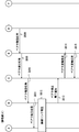
- FIG. 7 shows a processing procedure when there is no mobile terminal 1 in communication in the shared CNB 30.
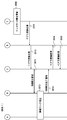
- FIG. 8 shows a processing procedure when there is a mobile terminal 1 in communication in the shared CNB 30.
- the mobile terminal 1 transmits a bearer recovery request.
- the base station 2 transfers the bearer recovery request received from the mobile terminal 1 to the mobility management node 3.
- the bearer recovery request is, for example, a Service request in EPS or a Service request in UMTS.
- step S403 the mobility management node 3 determines whether or not the mobile terminal 1 belonging to the same mobile terminal group as the transmission source mobile terminal 1 of the bearer recovery request and connected to the same base station 2 is communicating, that is, already shared. It is confirmed whether the CNB 30 and the bearer 40 are in use. This confirmation may be performed by making an inquiry to the communication management unit 7, as shown in step S404.
- the mobility management node 3 executes a procedure for establishing RAB (bearer 40 and radio bearer 50) (steps S405 to S407). That is, the mobility management node 3 transmits a RAB establishment request to the base station 2 (step S405).
- the RAB establishment request is, for example, S1-AP Initial Context Setup Request in EPS or Radio Access Bearer Assignment Request in UMTS.
- the base station 2 establishes a radio link (radio bearer 50) with the mobile terminal 1.
- step S407 the base station 2 transmits to the mobility management node 3 a RAB establishment completion notification indicating completion of setting of the RAB (bearer 40 and radio bearer 50).
- the RAB establishment completion notification is, for example, S1-AP Initial Context Setup Complete in EPS or RadioRadAccess Bearer Assignment Response in UMTS.
- steps S408 to S410 is the same as steps S114 to S116 in FIG. 4B or steps S210 to S212 in FIG. 5B. That is, in steps S408 to S410, the forwarding node 4 updates the endpoint identifier on the base station side of the bearer 40. In step S409, the external gateway 5 updates the packet filter (e.g. TFT) so that packets addressed to other mobile terminals 1 other than the mobile terminal 1 that transit during communication do not flow through the shared CNB 30.
- the packet filter e.g. TFT
- step S501 to S504 in FIG. 8 is the same as that in steps S401 to S404 in FIG. However, in step S503 of FIG. 8, it is determined that there is a mobile terminal 1 currently in communication.
- a plurality of terminals 1 in the same mobile terminal group connected to the same base station 2 cannot perform simultaneous communication. For this reason, the mobility management node 3 transmits a bearer recovery rejection response to the mobile terminal 1 via the base station 2 (steps S505 and S506).
- the bearer recovery rejection response is, for example, Service ⁇ ⁇ ⁇ Reject in EPS or service reject in UMTS.
- the mobility management node 3 may include a notification for back-off transmission of the next bearer recovery request of the mobile terminal 1 in the bearer recovery rejection response.
- the mobile terminal 1 suppresses transmission of the next bearer recovery request during a predetermined or randomly determined backoff time.
- the architecture and method according to Reference Example 1 share the shared CNB 30 for user packet transfer related to a plurality of mobile terminals 1. Furthermore, not only the end point setting of the shared CNB 30 but also the end point setting of the bearer 40 managed by the transfer node 4 is commonly used for user packet transfer of a plurality of mobile terminals 1. For this reason, the number of bearer contexts to be managed by the forwarding node 4 and the external gateway 5 is small. That is, typically, the forwarding node 4 and the external gateway 5 may maintain a context regarding one shared CNB 30 for a plurality of mobile terminals 1. Therefore, the architecture and method according to Reference Example 1 can reduce the processing load required for bearer maintenance in the forwarding node 4 and the external gateway 5.
- the CNB sharing architecture and method according to Reference Example 1 cannot allow multiple mobile terminals 1 in the same mobile terminal group connected to the same base station 2 to perform simultaneous communication.
- the mobility management node 3 establishes bearers from a plurality of mobile terminals 1 so as not to allocate a shared CNB 30 to a plurality of mobile terminals 1 in the same mobile terminal group connected to the same base station 2 at the same time.
- the fact that simultaneous communication cannot be performed means that (a) the communication frequency of a plurality of mobile terminals 1 belonging to the mobile terminal group is low, (b) the communication time of the mobile terminal 1 is short, or (c) the mobile terminal 1 communicates.
- delay it is allowed, it is not considered to be a problem. Therefore, it is considered that the architecture and method according to Reference Example 1 have a remarkable effect in application to applications having such communication characteristics, for example, some MachineMType Communication (MTC) applications.
- MTC MachineMType Communication
- Reference Example 2 shows an improvement for suppressing occurrence of call loss in an architecture that uses a shared CNB 30 for transferring user packets of a plurality of mobile terminals 1.
- FIG. 9 is a diagram illustrating a network and bearer configuration during simultaneous communication according to Reference Example 2.
- the operation of the mobile communication system according to Reference Example 2 is the same as that of Reference Example 1. That is, the mobile communication system according to Reference Example 2 can perform data packet transfer using only the shared CNB 30 as long as the communication timings of two or more mobile terminals 1 do not overlap.
- the mobile communication system according to Reference Example 2 can perform data packet transfer using only the shared CNB 30 as long as the communication timings of two or more mobile terminals 1 do not overlap.
- the endpoint setting of the shared CNB 30 managed by the external gateway 5 and the forwarding node 4 not only the endpoint setting of the bearer 40 managed by the forwarding node 4 Commonly used for. For this reason, the number of bearer contexts to be managed by the forwarding node 4 and the external gateway 5 is small, and the processing load required for bearer maintenance is reduced.
- the CN 20 according to Reference Example 2 adds an additional data bearer (ie additional CNB 31, additional bearer 41, and additional) for each of the second and subsequent mobile terminals 1.
- additional data bearer may be referred to as a temporary data bearer or a temporary bearer.
- the additional data bearer may be a normal data bearer that does not use the shared CNB 30. That is, when the communication timings of two or more mobile terminals 1 in the same mobile terminal group accidentally overlap, the mobile communication system according to Reference Example 2 temporarily generates a normal data bearer to cope with it. To do. Thereby, since the mobile communication system according to Reference Example 2 can enable simultaneous communication of a plurality of mobile terminals 1 belonging to the same mobile terminal group, occurrence of call loss can be suppressed.
- the CN 20 according to Reference Example 2 releases the setting in the CN 20 regarding the additional data bearer (additional CNB31, additional bearer 41, and additional radio bearer 51) in accordance with the end of communication of each of the second and subsequent mobile terminals 1. Good. More specifically, in the normal preservation function, the bearer context is maintained in the CN 20, whereas in the CN 20 according to the reference example 2, each of the second and subsequent mobile terminals 1 terminates the communication and transmits the IDLE. At the time of transition to the state, the setting in the CN 20 regarding the additional data bearer may be released. In the next communication of the mobile terminal 1 that has transitioned to the IDLE state, if the shared CNB 30 is unused, the shared CNB 30 is used.
- FIG. 10 is a flowchart illustrating an operation example of the mobility management node 3 according to the second reference example.
- the mobility management node 3 receives a bearer establishment request or a bearer recovery request from the mobile terminals 1 belonging to the terminal group for which the shared CNB 30 has been set.
- the mobility management node 3 determines whether or not the mobile terminal (UE) 1 belonging to the same mobile terminal group as the transmission source terminal of the bearer recovery request and connected to the same base station 2 is communicating. Determine whether.
- the mobility management node 3 When there is no mobile terminal 1 in communication (YES in step S12), the mobility management node 3 (the control unit 301), as in FIG. 5A, FIG. 5B, or FIG. The mobile terminal 1, the base station 2, and the forwarding node 4 are controlled so as to generate an associated RAB and assign it to the mobile terminal 1 (step S13).
- the mobility management node 3 executes a bearer establishment procedure to perform additional data bearers (CNB 31, bearer 41, and radio bearer 51). ) Is newly created, and the mobile terminal 1, the base station 2, the forwarding node 4, and the external gateway 5 are controlled so as to allocate this additional data bearer to the mobile terminal 1 (step S14).
- FIG. 11 shows an example of the bearer management table of the external gateway 5 according to Reference Example 2.
- the external gateway 5 sends a user packet addressed to the IP address assigned to the second mobile terminal 1 to the additional CNB 31 (and bearer management table). Modify packet filter based on management table. That is, the external gateway 5 adds an entry related to the added CNB 31 to the bearer management table.
- the IPv6 address “2001: DB8: 3: 1 :: / 64” is the additional CNB 31 specified by the IPv4 address “10.0.0.1” of the forwarding node 4 and the CNB identifier “00003”. It is associated.
- the IPv6 address “2001: DB8: 1: 1 :: / 64” is not a subnet number as an address band but an IPv6 address assigned to one mobile terminal 1.
- the external gateway 5 may determine the CNB that distributes the user packets by performing longest matching using the management table of FIG. As a result, the external gateway 5 can distribute the user packet of the second mobile terminal 1 to which the IPv6 address “2001: DB8: 1: 1 :: / 64” is assigned to the additional CNB 31 instead of the shared CNB 30.
- FIG. 12 shows an example of the bearer management table of the forwarding node 4 according to Reference Example 2. As can be understood from the comparison between FIG. 12 and FIG. 3, a third entry indicating the correspondence relationship between the additional CNB 31 and the additional bearer 41 is added in FIG. 12.
- the additional bearer 41 is specified by the IP address “10.0.1.1” of the base station 2 and the RAB identifier “00002”.
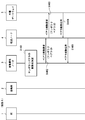
- FIG. 13A and FIG. 13B are sequence diagrams illustrating a processing example of a bearer establishment request from the second and subsequent mobile terminals 1 in the same mobile terminal group connected to the base station 2, and there is a mobile terminal 1 in communication This shows the processing procedure for doing this.
- a bearer establishment request may be processed in the same procedure as the sequence according to the reference example illustrated in FIGS. 5A and 5B.
- steps S601 to S605 in FIG. 13A is the same as steps S301 to S305 shown in FIG.
- the mobility management node 3 determines that there is a mobile terminal 1 that is currently communicating with respect to the terminal group to which the mobile terminal 1 that has transmitted the bearer establishment request belongs. Thereafter, in Reference Example 1 shown in FIG. 6, the mobility management node 3 rejects bearer establishment. On the other hand, in the reference example 2 shown in FIG. 13A, the mobility management node 3 transmits a bearer establishment request to the transfer node 4 in order to generate an additional bearer (step S606).
- the bearer establishment request in step S606 is a message for establishing a data bearer using a normal CNB instead of a shared CNB. Therefore, the bearer establishment request in step S606 includes the IP address issued by the mobility management node 3 to the mobile terminal 1, but does not include bearer sharing information.
- step S607 in response to receiving the bearer establishment request, the forwarding node 4 adds an entry related to the new data bearer to the bearer management table, and sends the bearer establishment request (including the IP address of the mobile terminal 1) to the external gateway 5.
- the external gateway 5 sets a normal CNB (that is, an additional CNB) for the IP address of the mobile terminal 1 specified in the bearer establishment request, and adds a new entry to the bearer management table. Then, the external gateway 5 transmits a bearer establishment response to the transfer node 4.
- the subsequent processing in steps S609 to S615 may be the same as the normal data bearer establishment procedure, for example, the procedure described in Section 5.3.1 “Attach” procedure ”of Non-Patent Document 1.
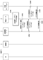
- step S703 in FIG. 14 the mobility management node 3 confirms that another mobile terminal 1 connected to the same base station 2 as the source mobile terminal 1 of the bearer recovery request and belonging to the same mobile terminal group is communicating. judge. Thereafter, in Reference Example 1 shown in FIG. 8, the mobility management node 3 rejects bearer recovery. On the other hand, in Reference Example 2 shown in FIG.
- the mobility management node 3 rejects bearer recovery and requests the mobile terminal 1 to detach (that is, disconnect from the CN 20) (steps S704 and S705).
- the bearer recovery rejection message transmitted in steps S704 and S705 in FIG. 14 includes a detach request. Accordingly, since the mobile terminal 1 transmits an attach request instead of a bearer recovery request, the mobility management node 3 sets an additional data bearer according to the sequence shown in FIGS. 13A and 13B in response to the reception of the attach request ( Step S706).
- the procedure in FIG. 14 is merely an example.
- the CN 20 and the RAN 10 execute a procedure similar to the bearer establishment procedure or the bearer addition procedure instead of the bearer restoration procedure.
- An additional data bearer may be established.
- the CN 20 and the RAN 10 may perform the same processing as that in steps S606 to S615 in the bearer establishment procedure shown in FIGS. 13A and 13B after step S703 in FIG.
- “addition” of a data bearer means that an individual data bearer is additionally set in the same connection (e.g. Packet Data Network (PDN) connection) as an existing data bearer.
- PDN Packet Data Network
- the procedure for adding a data bearer to an existing connection is described, for example, in Section 5.4.5 “UE requested bearer resource modification” of Non-Patent Document 1.
- step S804 the mobility management node 3 transmits a bearer establishment request to the transfer node 4 in order to establish a temporary additional CNB 31.
- the bearer establishment request in S804 is a message for establishing a data bearer using a normal CNB instead of a shared CNB. Therefore, the bearer establishment request in step S804 includes the IP address issued by the mobility management node 3 to the mobile terminal 1, but does not include bearer sharing information.
- step S805 in response to receiving the bearer establishment request, the forwarding node 4 adds an entry related to the new data bearer to the bearer management table, and sends the bearer establishment request (including the IP address of the mobile terminal 1) to the external gateway 5.
- the external gateway 5 sets a normal CNB (that is, an additional CNB) for the IP address of the mobile terminal 1 specified by the bearer establishment request, and adds a new entry to the bearer management table.
- step S807 the external gateway 5 transmits a bearer establishment response to the transfer node 4.
- step S808 the forwarding node 4 transmits a bearer establishment response to the mobility management node 3.
- processing in subsequent steps S809 to S813 may be the same as the normal bearer restoration procedure, for example, the procedure described in Section 5.3.4 “Service Request procedure” in Non-Patent Document 1.
- the CN 20 and the RAN 10 transmit the additional data bearer generated according to the procedure of FIG. 13A and FIG. 13B, FIG. 14, or FIG. 15A and FIG. 15B according to the end of the communication of the mobile terminal 1. You may release.
- the mobility management node 3 transfers the base station 2 and the transfer so that not only the additional RAB (bearer 41 and radio bearer 51) but also the setting of the additional CNB 31 is deleted.
- the node 4 and the external gateway 5 may be controlled.
- improvements 1 to 8 described below provide a technique for efficiently using an additional data bearer (or additional CNB) that is temporarily set.
- additional data bearer or additional CNB
- improvements 1 to 9 obtained by the inventors will be described in order.
- improvement 1 will be described, and improvements 2 to 9 will be described in order in the second to ninth embodiments.
- the configuration example of the mobile communication system according to the improvement 1 is the same as the configuration example of the reference example 2 shown in FIG.
- the mobile communication system according to the improvement 1 sets the upper limit number for the number of additional data bearers or the number of additional CNBs.
- the mobility management node 3 (control unit 301) manages the shared CNB 30 and the additional CNB 31 as described in the reference example 2.
- Management of the shared CNB 30 and the additional CNB 31 includes communicating with the forwarding node 4 and controlling the setting of the shared CNB 30 and the additional CNB 31 by the forwarding node 4 and the external gateway 5.
- the mobility management node 3 (control unit 301) according to the improvement 1 monitors the number of additional data bearers (or additional CNBs 31) set for the mobile terminal group, and the number of additional data bearers (or additional CNBs 31). Adjust so that does not exceed the upper limit. When the additional data bearer (or additional CNB 31) reaches the upper limit number, the mobility management node 3 may reject the setting of the new additional data bearer, or delete the old additional data bearer and create a new additional data bearer. May be set. According to the improvement 1, it can suppress that the additional data bearer set temporarily increases unnecessarily, and can use an additional data bearer efficiently.
- FIG. 16A and FIG. 16B are sequence diagrams illustrating an example of a bearer restoration procedure according to improvement 1.
- FIG. The processing in steps S901 to S903 is the same as the processing in steps S701 to S703 in FIG. 14 related to Reference Example 2 or steps S801 to S803 in FIG. 15A.
- step S904 the mobility management node 3 determines whether or not the number of temporary bearers already set by adding to the shared CNB 30 regarding the mobile terminal group has reached the upper limit.
- FIG. 1 the mobility management node 3 determines whether or not the number of temporary bearers already set by adding to the shared CNB 30 regarding the mobile terminal group has reached the upper limit.
- step S905 the mobility management node 3 determines a temporary bearer to be deleted from the set temporary bearers.
- the mobility management node 3 sets a new temporary bearer according to the procedure shown in the reference example 2 (for example, FIG. 14 or FIGS. 15A and 15B). That's fine.
- the number of temporary bearers to be deleted may be one or more.
- the mobility management node 3 can use (a) the elapsed time since the temporary bearer is set, (b) the elapsed time since the temporary bearer was last used, or (c) the usage frequency of the temporary bearer, or a combination thereof.
- Temporary bearers to be deleted may be determined. For example, the mobility management node 3 may determine the oldest temporary bearer as a temporary bearer to be deleted. In addition, the mobility management node 3 may determine the temporary bearer used last as the temporary bearer to be deleted. Further, the mobility management node 3 may determine a temporary bearer with the least usage frequency as a temporary bearer to be deleted. In addition, the mobility management node 3 may randomly determine a temporary bearer to be deleted from the set temporary bearers.
- Steps S906 to S910 indicate a bearer update procedure. That is, in steps S906 to S910, the mobility management node 3, the forwarding node 4, and the external gateway 5 update (modify) the settings of the temporary bearer to be deleted, thereby moving the source of the bearer restoration request in step S901.
- a temporary bearer for the terminal 1 is prepared.
- the mobility management node 3 transmits a bearer update request to the transfer node 4.
- the forwarding node 4 forwards the bearer update request to the external gateway.
- This bearer update request identifies the temporary bearer to be deleted (that is, updated or modified), and the user of the mobile terminal 1 (that is, the source of the bearer recovery request in step S901) to be associated with the updated temporary bearer It is sufficient to indicate a plain address.
- This bearer update request includes, for example, the bearer ID indicating the temporary bearer to be updated or modified, and the IP address assigned to the mobile terminal 1 that is the transmission source of the bearer recovery request in step S901.
- the bearer update request is, for example, Modify Bearer Request in EPS.
- step S908 the external gateway 5 updates the setting of the temporary CNB designated by the bearer update request. Specifically, the external gateway 5 may replace the IP address of the mobile terminal 1 associated with the temporary CNB specified by the bearer update request with the IP address specified by the bearer update request.
- step S909 the external gateway 5 transmits a bearer update response to the forwarding node 4.
- step S910 the forwarding node 4 transmits a bearer update response to the mobility management node 3.
- the subsequent processing in steps S911 to S915 may be the same as the normal bearer recovery procedure, for example, the procedure described in Section 5.3.4 “Service Request procedure” in Non-Patent Document 1.
- the mobility management node 3 may authenticate the mobile terminal 1 by communicating with the subscriber information database 6 after step S905 and before step S906.
- the improvement 2 relates to a modification of the improvement 1 described above.
- the configuration example of the mobile communication system according to the improvement 2 is the same as the configuration example of the reference example 2 shown in FIG. Similar to the improvement 1, the mobile communication system according to the improvement 2 sets the upper limit number for the number of additional data bearers or the number of additional CNBs.
- the forwarding node 4 (control unit 401) monitors the number of additional data bearers (or additional CNBs 31) set for the mobile terminal group, and the number of additional data bearers (or additional CNBs 31) is the upper limit number. Adjust so that it does not exceed.
- the forwarding node 4 may reject the setting of the new additional data bearer, or replace the old additional data bearer instead of setting the new additional data bearer. May be deleted.
- the improvement 2 like the improvement 1, it can suppress that the additional data bearer set temporarily is increased unnecessarily, and can use an additional data bearer efficiently.
- FIGS. 17A and 17B are sequence diagrams illustrating an example of a bearer restoration procedure according to the improvement 2.
- FIG. The processing in steps S1001 to S1003 is the same as the processing in steps S701 to S703 of FIG. 14 relating to Reference Example 2 or steps S801 to S803 of FIG. 15A.
- the mobility management node 3 transmits a bearer update request to the transfer node 4.
- This bearer update request may indicate the user plane address (for example, IP address) of the mobile terminal 1 (that is, the transmission source of the bearer recovery request in step S901).
- the message transmitted in step S1004 may be a bearer establishment request instead of a bearer update request.
- the bearer update request is, for example, Modify Bearer Request in EPS.
- the bearer establishment request is, for example, Create Session Request in EPS.
- step S1005 the forwarding node 4 determines whether or not the number of temporary bearers already set by adding to the shared CNB 30 regarding the mobile terminal group has reached the upper limit.
- FIG. 17A shows a case where the number of temporary bearers has reached the upper limit number.
- step S1006 the forwarding node 4 determines a temporary bearer to be deleted (or updated) from the set temporary bearers.
- the method for determining the temporary bearer to be deleted (or updated) may be the same as the method described for the improvement 1.
- the forwarding node 4 can set a new temporary bearer according to the procedure shown in the reference example 2 (for example, FIG. 14 or FIG. 15A and FIG. 15B). Good.
- the processing in steps S1007 to S1015 is the same as the processing in steps S907 to S915 shown in FIG. 16A and FIG.
- the mobility management node 3 may authenticate the mobile terminal 1 by communicating with the subscriber information database 6 after step S1003 and before step S1004, for example.
- the configuration example of the mobile communication system according to the improvement 3 is the same as the configuration example of the reference example 2 shown in FIG.
- the mobile terminal 1 when transmitting the bearer establishment request or the bearer recovery request, the mobile terminal 1 notifies the base station 2 or the CN 20 (specifically, the mobility management node 3) that the temporary bearer setting is not requested.
- the bearer establishment request or bearer recovery request includes, for example, a non-temporary flag.
- the non-temporary flag indicates whether a temporary bearer setting is required when the shared CNB 30 is in use for another mobile terminal 1.
- the mobile terminal 1 may notify the mobility management node that the temporary bearer setting is not requested.
- the mobility management node 3 rejects the bearer establishment or bearer recovery in response to the shared CNB 30 being in use.
- the mobility management node 3 may establish or restore a data bearer including the shared CNB 30 according to the procedure shown in the reference example 2, regardless of the contents of the non-temporary flag. According to the improvement 3, it can suppress that the additional data bearer set temporarily is increased, and an additional data bearer can be used efficiently.
- FIG. 18 is a sequence diagram showing an example of a bearer restoration procedure according to the improvement 3.
- the mobile terminal 1 transmits a bearer recovery request including a non-temporary flag.
- the mobile terminal 1 sets a non-temporary flag based on the importance or urgency of communication. In the example of FIG. 18, the non-temporary flag indicates that a temporary bearer is unnecessary.
- the base station 2 transfers a bearer recovery request including a non-temporary flag to the mobility management node 3.
- the mobility management node 3 confirms whether there is a mobile terminal 1 currently in communication with respect to the mobile terminal group to which the mobile terminal 1 that has transmitted the bearer recovery request belongs. .
- the mobility management node 3 determines that there is a mobile terminal 1 currently in communication. In step S1004, the mobility management node 3 checks the non-temporary flag included in the bearer recovery request. In the example of FIG. 18, the mobility management node 3 determines that a temporary bearer is unnecessary. Accordingly, the mobility management node 3 transmits a bearer recovery rejection response to the mobile terminal 1 via the base station 2 (steps S1105 and S1106).
- the configuration example of the mobile communication system according to the improvement 4 is the same as the configuration example of the reference example 2 shown in FIG.
- the end of communication of the second and subsequent mobile terminals 1 is shown as an example of the timing for releasing (deleting) the temporary bearer (additional bearer) setting held in the CN 20.
- the improvement 4 shows a specific procedure for releasing (deleting) the setting of the temporary CNB 31 held in the CN 20 when the communication of the mobile terminal 1 in the temporary bearer is terminated. According to the improvement 4, it can suppress that the additional data bearer set temporarily increases unnecessarily, and can use an additional data bearer efficiently.
- FIG. 19 is a sequence diagram illustrating an example of a procedure for deleting a temporary bearer (additional bearer) according to the improvement 4.
- the temporary CNB 31 that is, the bearer 41 and the radio bearer 51
- the temporary CNB 31 is released (deleted). Release of the RAB (that is, the bearer 41 and the radio bearer 51) associated with the temporary CNB 31 is, for example, release of the S1 bearer in EPS.
- step S1201 the base station 2 transmits a bearer release request to the mobility management node 3 when detecting the necessity of releasing the radio bearer for the mobile terminal 1.
- the bearer release request is, for example, S1-AP: S1 UE Context Release Request in EPS. Note that the bearer release request in step S1201 only needs to be transmitted when the base station 2 starts the RAB release procedure. That is, when the mobility management node 3 starts the RAB release procedure, step S1201 may not be performed.
- step S1202 the mobility management node 3 determines whether the RAB to be released is associated with the temporary bearer. When the RAB to be released is associated with the temporary bearer, the mobility management node 3 further determines to release (delete) the temporary CNB as shown in FIG. In steps S1203 to S1206, a procedure for deleting the shared CNB 30 is performed. This procedure may be the same as the procedure for deleting the bearer context held in the CN 20 when the mobile terminal 1 detaches.
- step S1203 the mobility management node 3 transmits a bearer deletion request to the transfer node 4.
- This bearer deletion request requests the transfer node 4 to delete the temporary CNB 31 instead of releasing the temporary RAB (specifically, the bearer 51).
- the bearer deletion request in step S1203 includes an identifier (for example, a bearer ID indicating a temporary bearer) necessary for specifying the temporary CNB 31 to be deleted.
- the bearer deletion request in step S1203 is, for example, Delete Session Request in EPS.
- the forwarding node 4 deletes the temporary CNB 31 specified based on the bearer deletion request from the mobility management node 3.
- step S1204 the forwarding node 4 transmits a bearer deletion request to the external gateway 5.
- the external gateway 5 deletes the temporary CNB 31 specified based on the bearer deletion request from the forwarding node 4.
- the external gateway 5 transmits a bearer deletion response to the transfer node 4 in order to notify the completion of deletion of the temporary CNB 31.
- the forwarding node 4 transmits a bearer deletion response to the mobility management node 3.
- the bearer deletion response in steps S1205 and S1206 is, for example, Delete Session Response in EPS.
- step S1207 the mobility management node 3 transmits a bearer release instruction to the base station 2 in order to instruct the release of the temporary RAB (specifically, the bearer 51).
- the bearer release instruction in step S1207 is, for example, S1-AP: S1 UE Context Release Command in EPS.
- the base station 2 transmits a message for releasing the radio link to the mobile terminal 1 in step S1208.
- the message in step S1208 is, for example, “RRC” connection “Release” message in EPS.
- step S1209 the base station 2 notifies the mobility management node 3 of the completion of temporary RAB release.
- the notification in step S1209 is, for example, S1-AP: S1 UE Context Release Complete in EPS.
- the configuration example of the mobile communication system according to the improvement 5 is the same as the configuration example of the reference example 2 shown in FIG.
- the CN 20 according to the improvement 5 deletes the temporary CNB 31 in response to reception of a bearer restoration request from the mobile terminal 1 that has communicated with the temporary bearer in the past. More specifically, the CN 20 (for example, the mobility management node 3) confirms the usage status of the shared CNB 30 when receiving a bearer recovery request from the mobile terminal 1 that has communicated with the temporary bearer in the past. If the shared CNB 30 is unused, the CN 20 (for example, the mobility management node 3) deletes the temporary CNB 31 and restores the bearer using the shared CNB 30 for the mobile terminal 1. Thereby, the improvement 5 can suppress that the additional data bearer set temporarily increases unnecessarily, and can use an additional data bearer efficiently.
- 20A and 20B are sequence diagrams illustrating an example of a procedure for deleting a temporary bearer (additional bearer) according to improvement 5.
- the mobile terminal 1 that has communicated with the temporary bearer in the past transmits a bearer recovery request.
- the base station 2 transfers the bearer recovery request to the mobility management node 3.
- the mobility management node 3 confirms whether the mobile terminal 1 in communication exists in the shared CNB 30 in response to receiving the bearer recovery request. In the example of FIG. 20A, the mobility management node 3 determines that there is no mobile terminal 1 that is currently in communication, that is, the shared CNB 30 is unused.
- Steps S1304 to S1308 show a procedure for deleting the temporary CNB 31 and updating the setting of the shared CNB 30 for the mobile terminal 1 that has transmitted the bearer recovery request.
- the shared CNB 30 is prepared for the mobile terminal 1 that is the transmission source of the bearer recovery request.
- the mobility management node 3 transmits a bearer deletion request to the transfer node 4.
- This bearer deletion request identifies the temporary bearer to be deleted (temporary CNB 31) and indicates the user plane address of the mobile terminal 1 (that is, the source of the bearer recovery request in step S1301) to be associated with the updated shared CNB 30. That's fine.
- This bearer deletion request includes, for example, the bearer ID indicating the temporary bearer to be deleted and the IP address assigned to the mobile terminal 1 that is the transmission source of the bearer recovery request in step S1301.
- the bearer update request is, for example, Delete Session Request in EPS.
- the forwarding node 4 deletes the setting (context) related to the temporary CNB 31 and forwards the bearer deletion request to the external gateway in step S1305.
- the external gateway 5 deletes the setting of the temporary CNB 31 designated by the bearer deletion request.
- the external gateway 5 updates the packet filter of the shared CNB 30 using the IP address assigned to the mobile terminal 1 that is the transmission source of the bearer recovery request. That is, the external gateway 5 updates the packet filter so that the downlink user packet in which the IP address of the mobile terminal 1 that is the transmission source of the bearer recovery request is designated as the destination is sent to the shared CNB 30.
- step S1307 the external gateway 5 transmits a bearer deletion response to the transfer node 4 in order to notify the completion of deletion of the temporary CNB 31.
- step S1308 the forwarding node 4 transmits a bearer deletion response to the mobility management node 3.
- the bearer deletion response in steps S1307 and S1308 is, for example, Delete Session Response in EPS.
- the subsequent processing in steps S1309 to S1313 may be the same as the normal bearer restoration procedure, for example, the procedure described in Section 5.3.4 “Service Request” of Non-Patent Document 1.
- the mobility management node 3 may authenticate the mobile terminal 1 by communicating with the subscriber information database 6 after step S1308 and before step S1309, for example.
- the mobility management node 3 may authenticate the mobile terminal 1 by communicating with the subscriber information database 6 after step S1303 and before step S1304, for example.
- the configuration example of the mobile communication system according to the improvement 6 is the same as the configuration example of the reference example 2 shown in FIG.
- the mobility management node 3 leads the procedure for deleting the temporary bearer (temporary CNB 31).
- the mobility management node 3 detects an unused temporary CNB 31 and activates a deletion procedure for the temporary CNB 31.
- the mobility management node 3 can use (a) the elapsed time since the temporary bearer is set, (b) the elapsed time since the temporary bearer was last used, or (c) the usage frequency of the temporary bearer, or a combination thereof.
- the unused temporary CNB 31 to be deleted may be detected.
- the mobility management node 3 may determine the temporary CNB 31 for which a predetermined time has elapsed since the last use as a deletion target. Thereby, it is possible to prevent the setting of the unused temporary CNB 31 from remaining. Therefore, the improvement 6 can suppress the additional data bearer set up temporarily increasing unnecessarily, and can use an additional data bearer efficiently.
- FIG. 21 is a sequence diagram showing an example of a procedure for deleting the temporary bearer (additional bearer) according to the improvement 6.
- the mobility management node 3 determines to delete a temporary bearer (specifically, the temporary CNB 31) that has not been used for a long time.
- the mobility management node 3 transmits a bearer deletion request to the transfer node 4.
- This bearer deletion request requests the transfer node 4 to delete the temporary CNB 31.
- the bearer deletion request in step S1402 includes an identifier (for example, a bearer ID indicating a temporary bearer) necessary for specifying the temporary CNB 31 to be deleted.
- the bearer deletion request in step S1402 is, for example, Delete Session Request in EPS.
- the forwarding node 4 deletes the temporary CNB 31 specified based on the bearer deletion request from the mobility management node 3.
- the forwarding node 4 transmits a bearer deletion request to the external gateway 5.
- the external gateway 5 deletes the temporary CNB 31 specified based on the bearer deletion request from the forwarding node 4.
- the external gateway 5 transmits a bearer deletion response to the transfer node 4 in order to notify the completion of deletion of the temporary CNB 31.
- the forwarding node 4 transmits a bearer deletion response to the mobility management node 3.
- the bearer deletion response in steps S1404 and S1405 is, for example, Delete Session Response in EPS.
- the improvement 7 relates to the modification of the improvement 6 described above.
- the configuration example of the mobile communication system according to the improvement 7 is the same as the configuration example of the reference example 2 shown in FIG.
- the forwarding node 4 leads the temporary bearer (temporary CNB 31) deletion procedure.
- the forwarding node 4 detects an unused temporary CNB 31 and activates a deletion procedure for the temporary CNB 31.
- the forwarding node 4 may detect the unused temporary CNB 31 to be deleted based on the same method as described in the improvement 6.
- the forwarding node 4 since the forwarding node 4 is responsible for user packet forwarding, the amount of data flowing through the temporary CNB 31 can be monitored.
- the forwarding node 4 may obtain the unused period or the usage frequency of the temporary CNB 31 using the monitoring result of the data amount flowing through the temporary CNB 31.
- the improvement 7 similarly to the improvement 6, it is possible to prevent the setting of the unused temporary CNB 31 from remaining. Therefore, the improvement 7 can suppress that the additional data bearer set temporarily increases unnecessarily, and can use an additional data bearer efficiently.
- FIG. 22 is a sequence diagram showing an example of a procedure for deleting the temporary bearer (additional bearer) according to the improvement 7.
- the forwarding node 4 determines to delete a temporary bearer (specifically, the temporary CNB 31) that has not been used for a long time.
- the forwarding node 4 notifies the mobility management node 3 of an unused temporary CNB 31.
- the notification in step S1502 includes, for example, a bearer ID indicating an unused temporary CNB 31.
- the mobility management node 3 starts a procedure for deleting the temporary CNB 31 (steps S1503 to S1506).
- the processing in steps S1503 to S1506 is the same as the processing in steps S1402 to S1405 shown in FIG.
- the configuration example of the mobile communication system according to the improvement 8 is the same as the configuration example of the reference example 2 shown in FIG.
- the mobile terminal 1 leads the procedure for deleting the temporary bearer (temporary CNB 31). Specifically, when the mobile terminal 1 that has communicated with the temporary bearer in the past transmits a bearer recovery request to the mobility management node 3, it also transmits a temporary bearer deletion request. For example, the mobile terminal 1 may transmit a bearer restoration request including a “deletion flag” indicating a temporary bearer deletion request. When the mobility management node 3 receives a bearer recovery request including a deletion flag, the mobility management node 3 checks the usage status of the shared CNB 30.
- the mobility management node 3 deletes the temporary CNB 31 associated with the mobile terminal 1 that has transmitted the bearer recovery request, and uses the shared CNB 30 for the mobile terminal 1. To recover. Thereby, the improvement 8 can suppress that the additional data bearer set temporarily increases unnecessarily, and can use an additional data bearer efficiently. Furthermore, in the improvement 8, the mobile terminal 1 can request the CN 20 to delete the temporary bearer.
- step S1601 the mobile terminal 1 that has communicated with the temporary bearer in the past transmits a bearer recovery request.
- This bearer recovery request includes a “deletion flag” indicating a temporary bearer deletion request.
- step S1602 the base station 2 transfers the bearer recovery request to the mobility management node 3.
- step S1603 the mobility management node 3 confirms whether there is a mobile terminal 1 in communication in the shared CNB 30 in response to receiving the bearer recovery request including the deletion flag.
- the mobility management node 3 determines that there is no mobile terminal 1 currently in communication, that is, the shared CNB 30 is unused.
- Steps S1604 to S1608 show procedures for deleting the temporary CNB 31 and updating the setting of the shared CNB 30 for the mobile terminal 1 that has transmitted the bearer recovery request.
- the processing in steps S1604 to S1608 is the same as the processing in steps S1304 to S1308 shown in FIGS. 20A and 20B regarding the improvement 5.
- the subsequent processing in steps S1609 to S1613 may be the same as the normal bearer recovery procedure, for example, the procedure described in Section 5.3.4 “Service Request” procedure of Non-Patent Document 1.
- the mobility management node 3 may authenticate the mobile terminal 1 by communicating with the subscriber information database 6 after step S1608 and before step S1609, for example.
- the mobility management node 3 may authenticate the mobile terminal 1 by communicating with the subscriber information database 6 after step S1603 and before step S1604, for example.
- the configuration example of the mobile communication system according to the improvement 9 is the same as the configuration example of the reference example 2 shown in FIG.
- the mobile terminal 1 leads the temporary bearer (temporary CNB 31) deletion procedure.
- the mobile terminal 1 to which the temporary bearer is assigned transmits a control message (for example, a NAS message) including a temporary bearer deletion request when transitioning to the IDLE state.
- the mobile terminal 1 may transmit a control message including a “deletion flag” indicating a temporary bearer deletion request.
- the base station 2 transfers the control message including the “delete flag” to the mobility management node 3.
- the mobility management node 3 When the mobility management node 3 receives a control message including a deletion flag, the mobility management node 3 performs a temporary bearer deletion procedure associated with the mobile terminal 1. Thereby, improvement 9 can control that the additional data bearer set up temporarily increases unnecessarily, and can use an additional data bearer efficiently. Furthermore, in the improvement 9, the mobile terminal 1 can request the CN 20 to delete the temporary bearer.
- FIG. 24 is a sequence diagram illustrating an example of a procedure for deleting a temporary bearer (additional bearer) according to improvement 9.
- the mobile terminal 1 to which the temporary bearer is assigned transmits a control message including the “delete flag”.
- the base station 2 transfers the control message to the mobility management node 3.
- the mobility management node 3 determines to delete the temporary bearer in response to receiving the control message including the deletion flag, and is associated with the temporary CNB31 release procedure (steps S1704 to S1707) and the temporary CNB31.
- the RAB that is, bearer 41 and radio bearer 51 release procedure (steps S1708 to S1710) is started.
- the temporary CNB 31 release procedure in steps S1704 to S1707 is the same as steps S1402 to S1405 shown in FIG. Further, the RAB release procedure in steps S1708 to S1710 is the same as steps S1207 to S1209 shown in FIG.
- the first to ninth embodiments may be implemented in combination as appropriate.
- Non-transitory computer readable media include various types of tangible storage media (tangible storage medium). Examples of non-transitory computer-readable media include magnetic recording media (eg flexible disks, magnetic tapes, hard disk drives), magneto-optical recording media (eg magneto-optical discs), CD-ROMs (Read Only Memory), CD-Rs, CD-R / W, semiconductor memory (for example, mask ROM, PROM (Programmable ROM), EPROM (Erasable ROM), flash ROM, RAM (random access memory)) are included.
- the program may also be supplied to the computer by various types of temporary computer-readable media. Examples of transitory computer readable media include electrical signals, optical signals, and electromagnetic waves.
- the temporary computer-readable medium can supply the program to the computer via a wired communication path such as an electric wire and an optical fiber, or a wireless communication path.
- the mobile communication system according to the first and second embodiments may be other mobile communication systems.
Landscapes
- Engineering & Computer Science (AREA)
- Computer Networks & Wireless Communication (AREA)
- Signal Processing (AREA)
- Mobile Radio Communication Systems (AREA)
Abstract
コアネットワーク(CN)(20)は、複数の移動端末(1)のユーザパケット転送のために共用される共用CNB(30)を、転送ノード(4)と外部ゲートウェイ(5)の間に設定する。CN(20)は、1台の移動端末のみが通信を行う際に、当該移動端末のために共用CNB(30)を使用する。CN(20)は、1台より多い移動端末が同時に通信を行う際に、これらの移動端末に含まれる第1の移動端末のために共用CNB(30)を使用し、これらの移動端末に含まれる1台以上の他の移動端末のために1つ以上のテンポラリCNBを追加的に設定して使用する。一態様では、CN(20)は、テンポラリCNBの数が上限数を超えないよう調整する。
Description
本出願は、移動通信システムに関し、例えば、ユーザパケット転送のための通信制御に関する。
多元接続方式の移動通信システムは、時間、周波数、及び送信電力のうち少なくとも1つを含む無線リソースを複数の移動端末の間で共有することで、複数の移動端末が実質的に同時に無線通信を行うことを可能としている。代表的な多元接続方式は、TDMA(Time Division Multiple Access)、FDMA(Frequency Division Multiple Access)、CDMA(Code Division Multiple Access)、若しくはOFDMA(Orthogonal Frequency Division Multiple Access)又はこれらの組み合わせである。本明細書で用いる移動通信システムの用語は、特に断らない限り多元接続方式の移動通信システムを意味する。
移動通信システムは、移動端末及びネットワークを含む。ネットワークは、無線アクセスネットワーク(Radio Access Network(RAN))及びコアネットワーク(Mobile Core Network(CN))を含む。移動端末は、RAN及びCNを介して外部ネットワーク(例えば、インターネット、パケットデータネットワーク、Public Switched Telephone Networks(PSTN))と通信する。移動通信システムは、例えば、3rd Generation Partnership Project(3GPP)のUniversal Mobile Telecommunications System(UMTS)又はEvolved Packet System(EPS)である。RANは、例えば、Universal Terrestrial Radio Access Network(UTRAN)、又はEvolved UTRAN(E-UTRAN)である。CNは、例えば、General Packet Radio Service(GPRS)パケットコア、又はEvolved Packet Core(EPC)である。
移動通信システムは、一般的に、外部ネットワークと移動端末との間でユーザパケットを転送するためのデータベアラを移動端末毎に作成する必要がある。なぜなら、移動端末のモビリティを提供するためにパケット転送ルートの速やかな切り替え・再配置が必要とされるためである。データベアラは、例えば、UMTSベアラ(General Packet Radio Service(GPRS)ベアラ)、又はEPSベアラである。データベアラは、CNに設定されるコアネットワークベアラ(以下、CNBと呼ぶ)及びRANに設定される無線アクセスベアラ(以下、RABと呼ぶ)を含む。
CNBは、CNに配置される外部ゲートウェイと転送ノードの間に設定されるトンネル、つまり論理的な伝送路、である。外部ゲートウェイは、外部ネットワークとの境界に配置されるゲートウェイノードである。転送ノードは、RANとの境界に配置されるノードである。CNBは、例えば、UMTSのCNB(つまり、GPRS Tunneling Protocol(GTP)トンネル)、又はEPSのS5/S8ベアラ(つまり、GTPトンネル)である。また、外部ゲートウェイは、例えば、Gateway GPRS Support Node(GGSN)、又はPacket Data Network Gateway(P-GW)である。転送ノードは、例えば、Serving GPRS Support Node(SGSN)のユーザプレーン機能、又はServing Gateway(S-GW)である。
RABは、CNの転送ノードと移動端末の間に設定されるベアラである。RABは、RANとCNの間に設定されるベアラと、無線ベアラを含む。RANとCNの間に設定されるベアラは、Radio Link Control(RLC)及びRadio Resource Control(RRC)を担うRANノードとCNの転送ノードの間に設定される。無線ベアラは、RAN内において、上述のRANノードと移動端末の間に設定される。RLC及びRRCを担うRANノードは、例えば、UMTSのRadio Network Controller(RNC)、又はEPSの基地局(evolved NodeB(eNB))である。RANとCNの間に設定されるベアラは、例えば、UMTSのIuベアラ(つまり、GTPトンネル)、又はEPSのS1ベアラ(つまり、GTPトンネル)である。無線ベアラは、例えば、UMTSのUuベアラ、又はEPSのLTE-Uuベアラである。
つまり、CNは、CNBを移動端末毎に確立する必要がある。転送ノードは、CNBに関するトンネル設定として、トンネル識別子(トンネルエンドポイント識別子)及び外部ゲートウェイのユーザプレーン・アドレス(e.g. Internet Protocol(IP)アドレス)などを記憶し管理しなければならない。外部ゲートウェイは、例えば、CNにアタッチする移動端末に対して外部ネットワークに接続するためのユーザプレーン・アドレス(e.g. IPアドレス)を割り当てるとともに、CNBに関するトンネル設定、課金制御、及びQuality of Service(QoS)制御など行う。
例えば、非特許文献1は、EPSにおいて、移動端末のCNへのアタッチ、又はサービス要求等に応じて、移動端末のユーザパケットを転送するためのデータベアラ(つまり、EPSベアラ)を確立・復旧する手順を記載している。
3GPP TS 23.401 V9.13.0, "General Packet Radio Service (GPRS) enhancements for Evolved Universal Terrestrial Radio Access Network (E-UTRAN) access", 2012年6月
上述したように、CNは、CNBを移動端末毎に生成し、これらを管理しなければならない。例えば、CNB数の増大に対応可能とするためには、外部ゲートウェイ及び転送ノードは、トンネル設定・管理、及びIPアドレス割当等の処理の増大に対応可能な能力が求められる。具体的には、転送ノードの性能増強、又は追加設置等が必要となる。この問題に対処するために、本件発明者は、過去の2件の日本特許出願 特願2011-217383号及び特願2012-214050号において、複数の移動端末のユーザパケット転送のために1つのCNBを共用することが可能なアーキテクチャ及び方法を提案している。
本出願は、日本特許出願 特願2011-217383号及び特願2012-214050号で提案したアーキテクチャ及び方法の改良を提供するものである。具体的には、本出願に示される目的の1つは、複数の移動端末のユーザパケット転送のために1つのCNBを共用するアーキテクチャにおいて、一時的に設定される追加CNBを効率的に利用できるようにするための改良を提供することである。これらの課題を含む幾つかの課題に対処するために発明者により得られた技術思想は、後述する実施形態の記述及び図面によって明らかにされる。
一態様において、移動通信システムは、基地局を含む無線アクセスネットワーク、転送ノード及び外部ゲートウェイを含むコアネットワーク、及び前記無線アクセスネットワークに接続する複数の移動端末を含む。前記コアネットワークは、前記複数の移動端末のユーザパケット転送のために共用される共用コアネットワークベアラ(CNB)を、前記転送ノードと前記外部ゲートウェイの間に設定する。そして、前記コアネットワークは、前記複数の移動端末に属する1台の移動端末のみが通信を行う際に、前記1台の移動端末のユーザパケット転送のために前記共用CNBを使用する。さらに、前記コアネットワークは、前記複数の移動端末に属する1台より多い移動端末が同時に通信を行う際に、前記1台より多い移動端末に含まれる第1の移動端末のユーザパケット転送のために前記共用CNBを使用し、前記1台より多い移動端末に含まれる1台以上の他の移動端末のユーザパケット転送のために1つ以上のテンポラリCNB(追加CNB)を追加的に設定して使用する。
上述した一態様において、前記コアネットワークは、前記1又は複数のテンポラリCNBの数が予め定められた上限数を超えないように調整してもよい。
上述した一態様において、前記複数の移動端末の各々は、ベアラ確立要求又はベアラ復旧要求を前記コアネットワークに送信する際に、テンポラリCNBを必要とするか否かを示す通知を前記コアネットワークに送信してもよい。
上述した一態様において、前記コアネットワークは、必要に応じてテンポラリCNBの削除手順を実行してもよい。
上述した一態様において、前記コアネットワークは、過去にテンポラリCNBにおいて通信していた移動端末から、テンポラリCNBの削除要求を示すベアラ復旧要求を受信してもよい。
上述した一態様において、前記コアネットワークは、テンポラリCNBでの通信を終了した移動端末から、テンポラリCNBの削除要求を受信してもよい。
上述した一態様及びその変形によれば、複数の移動端末のユーザパケット転送のために1つのCNBを共用するアーキテクチャにおいて、一時的に設定される追加CNBを効率的に利用できるようにするための改良を提供することができる。
以下では、具体的な実施形態について、図面を参照しながら詳細に説明する。各図面において、同一又は対応する要素には同一の符号が付されており、説明の明確化のため、必要に応じて重複説明は省略される。
<第1の実施形態>
図1は、本実施形態を含む幾つかの実施形態に係る移動通信システムの構成例を示している。移動通信システムは、RAN10及びCN20を含む。RAN10は、基地局2を含む。基地局2は、無線アクセス技術により移動端末(UE)1と接続する。移動端末1は、無線インタフェースを有し、無線アクセス技術により基地局2に接続し、RAN10を介してCN20へ接続する。そして、移動端末1は、RAN10及びCN20を介して外部ネットワーク9と通信する。外部ネットワーク9は、インターネット、パケットデータネットワーク若しくはPSTN、又はこれらの組み合わせである。RAN10は、例えば、UTRAN若しくはE-UTRAN、又はこれらの組み合わせである。UTRANにおいては、基地局2はNodeB及びRNCに対応する。E-UTRANにおいては、基地局2はeNBに対応する。
図1は、本実施形態を含む幾つかの実施形態に係る移動通信システムの構成例を示している。移動通信システムは、RAN10及びCN20を含む。RAN10は、基地局2を含む。基地局2は、無線アクセス技術により移動端末(UE)1と接続する。移動端末1は、無線インタフェースを有し、無線アクセス技術により基地局2に接続し、RAN10を介してCN20へ接続する。そして、移動端末1は、RAN10及びCN20を介して外部ネットワーク9と通信する。外部ネットワーク9は、インターネット、パケットデータネットワーク若しくはPSTN、又はこれらの組み合わせである。RAN10は、例えば、UTRAN若しくはE-UTRAN、又はこれらの組み合わせである。UTRANにおいては、基地局2はNodeB及びRNCに対応する。E-UTRANにおいては、基地局2はeNBに対応する。
基地局2は、移動端末1のユーザパケット転送のために、移動端末1との間で無線ベアラ50を確立し、転送ノード4との間でベアラ40を確立する。ベアラ40は、UTRANではIuベアラに対応し、E-UTRANではS1ベアラに対応する。ベアラ40及び無線ベアラ50の組み合わせは、無線アクセスベアラ(RAB)に相当する。
CN20は、主に移動通信サービスを提供するオペレータによって管理されるネットワークである。CN20は、Packet Switched(PS)コアを含む。CN20は、例えば、EPC若しくはGPRSパケットコア、又はこれらの組み合わせである。図1の例では、CN20は、移動管理ノード3、転送ノード4、外部ゲートウェイ5、及び加入者情報データベース6を含む。また、CN20は、通信管理ユニット7を含んでもよい。
移動管理ノード3は、コントロールプレーンのノードであり、移動端末1のモビリティ管理(e.g. 位置登録)、及びベアラ管理(e.g. ベアラ確立、ベアラ構成変更、ベアラ解放)などを行う。制御部301は、少なくともベアラ管理のためにコアネットワーク20及び基地局2を制御する。例えば、UMTSの場合、移動管理ノード3は、SGSNのコントロールプレーン機能を含む。また、EPSの場合、移動管理ノード3は、MMEを含む。移動管理ノード3は、基地局2との間で制御メッセージ(e.g. S1APメッセージ)を送受信し、移動端末1との間でNon-Access Stratum(NAS)メッセージを送受信する。NASメッセージは、RAN10で終端されず、RAN10の無線アクセス方式に依存することなく、移動端末1とCN20の間で透過的に送受信される制御メッセージである。移動端末1からCN20に送られるNASメッセージは、アタッチ要求、ベアラ確立要求、ベアラ復旧要求、及び位置更新要求などのNAS要求メッセージを含む。例えば、EPSの場合、移動端末1からのNAS要求メッセージは、Attach Request、Service Request、PDN connectivity request、Bearer Resource Allocation Request、Bearer Resource Modification Request、TAU (Tracking Area Update) Request、及びRAU (Routing Area Update) Request等を含む。EPSでのアタッチ要求(Attach Request)は、移動端末1のCN20への接続だけでなく、デフォルトベアラの確立を引き起こす。したがって、EPSでのアタッチ要求(Attach Request)は、ベアラ確立要求を含むと言うことができる。
転送ノード4は、RAN10(具体的には基地局2)と外部ゲートウェイ5の間で移動端末1のユーザパケットを転送する。転送ノード4は、移動端末1のユーザパケット転送のために、基地局2との間でベアラを確立し、外部ゲートウェイ5との間でコアネットワークベアラ(CNB)30を確立する。制御部401は、移動管理ノード3及び外部ゲートウェイ5と制御メッセージを交換し、基地局2とのベアラの設定およびCNB30の設定を行う。転送ノード4(制御部401)は、一例において、移動端末1に付与すべきユーザプレーン・アドレス(e.g. IPアドレス)の払い出しを行ってもよい。例えば、UMTSの場合、転送ノード4は、SGSNのユーザプレーン機能を含む。また、EPSの場合、転送ノード4は、S-GWを含む。CNB30は、例えば、UMTSにおけるCNB、又はEPSにおけるS5/S8ベアラに対応する。なお、後述するように、本実施形態におけるCNB30は、複数の移動端末1のユーザパケット転送のために共用される。以下では、移動端末単位で設定される(又は1つの移動端末のためだけに使用される)通常のCNBと区別するために、CNB30を「共用CNB」と呼ぶ。また、以下では、共用CNB30を共用する複数の移動端末1を「移動端末グループ」と呼ぶことがある。共用CNB30は、1つの基地局2に接続する複数の移動端末1の間で共用される場合もあるし、複数の基地局2に接続する複数の移動端末1の間で共用される場合もある。
外部ゲートウェイ5は、転送ノード4と外部ネットワーク9の間で移動端末1のユーザパケットを転送する。外部ゲートウェイ5は、転送ノード4との間で共用CNB30を確立する。制御部501は、転送ノード4と制御メッセージを交換し、共用CNB30の設定を行う。外部ゲートウェイ5(制御部501)は、一例において、移動端末1に付与すべきユーザプレーン・アドレス(e.g. IPアドレス)の払い出しを行ってもよい。例えば、UMTSの場合、外部ゲートウェイ5は、GGSNを含む。また、EPSの場合、外部ゲートウェイ5は、P-GWを含む。
加入者情報データベース6は、移動端末1の加入者情報を保持するデータベースであり、例えばHome Subscriber Server(HSS)又はHome Location Server(HLR)がこれに相当する。加入者情報データベース6は、移動管理ノード3等に加入者情報を提供する機能を有する。加入者情報データベース6は、加入者サーバと呼ぶこともできる。管理部601は、移動管理ノード3の要求に応答して、移動管理ノード3に加入者情報を送信する。加入者情報データベース6(管理部601)は、一例において、移動端末1に付与すべきユーザプレーン・アドレス(e.g. IPアドレス)の払い出しを行ってもよい。
続いて以下では、本実施形態の前提となる本件発明者等によって考案されたCNB共用のアーキテクチャ及び方法を含む参考例1及び参考例2について図2~15を用いて説明する。参考例1は、本件発明者の過去の日本特許出願 特願2011-217383号に記載されている。参考例2は、本件発明者の過去の日本特許出願 特願2012-214050号に記載されている。なお、参考例1及び2は、本件出願時点において公知なものではなく、本件発明者によって所有されている技術思想である。
(参考例1)
参考例1では、CN20は、転送ノード4において共用CNB30をRAB(具体的にはベアラ40)と一対一に対応付ける。CN20は、移動端末グループに属する複数の移動端末1のうち任意の1台が通信を行う際に、この任意の1台のために共用CNB30及びベアラ40を使用する。つまり、参考例1では、共用CNB30において同時に通信可能な移動端末の数が1台に制限される。後述するように、移動管理ノード3は、複数の移動端末1が共用CNB30を同時に使用しないように、複数の移動端末1からのベアラ確立要求(e.g. Attach Request)及びベアラ復旧要求(e.g. Service Request)を調停する。また、外部ゲートウェイ5は、複数の移動端末1に関するユーザデータが共用CNB30に流入しないように、共用CNB30のパケットフィルタ(e.g. traffic Flow Template(TFT))を適切に設定する。これにより、転送ノード4が特別な動作を行うこと無く、共用CNB30を複数の移動端末1のユーザパケット転送のために利用できる。
参考例1では、CN20は、転送ノード4において共用CNB30をRAB(具体的にはベアラ40)と一対一に対応付ける。CN20は、移動端末グループに属する複数の移動端末1のうち任意の1台が通信を行う際に、この任意の1台のために共用CNB30及びベアラ40を使用する。つまり、参考例1では、共用CNB30において同時に通信可能な移動端末の数が1台に制限される。後述するように、移動管理ノード3は、複数の移動端末1が共用CNB30を同時に使用しないように、複数の移動端末1からのベアラ確立要求(e.g. Attach Request)及びベアラ復旧要求(e.g. Service Request)を調停する。また、外部ゲートウェイ5は、複数の移動端末1に関するユーザデータが共用CNB30に流入しないように、共用CNB30のパケットフィルタ(e.g. traffic Flow Template(TFT))を適切に設定する。これにより、転送ノード4が特別な動作を行うこと無く、共用CNB30を複数の移動端末1のユーザパケット転送のために利用できる。
参考例1では、転送ノード4は、複数の移動端末1のユーザパケット転送のために、1つの共用CNB30と1つのベアラ40の対応関係を管理しておけばよく、移動端末1単位でのユーザパケットの振り分けを行わなくてもよい。したがって、転送ノード4が管理すべきベアラ管理表の容量を削減でき、転送ノード4の処理量を削減できる。また、参考例1と同様に、外部ゲートウェイ5が扱うCNB数も減少するため、外部ゲートウェイ5が管理すべきベアラ管理表の容量を削減できる。
図2は、参考例1における外部ゲートウェイ5のベアラ管理表の一例を示している。図2の例では、共用CNB30を識別するための情報(つまり、転送ノード4のIPアドレス、CNB識別子)は、移動端末1に払いだしたIPアドレスではなく、移動端末グループに払いだしたIPアドレス帯域と対応付けられる。図2に示された2つの移動端末グループのIPアドレス帯域は、IPv6アドレスで表されており、プレフィックス長が60ビットであるサブネット番号を示している。例えば、サブネット番号“2001:DB8:1::/60”で示されるアドレス帯域に含まれるIPv6アドレスが割り当てられた複数の移動端末1のユーザパケットの全ては、転送ノード4のIPv4アドレス“10.0.0.1”及びCNB識別子“00001”によって特定される共用CNB30に転送される。
図3は、参考例1における転送ノード4のベアラ管理表の一例を示している。参考例1において、転送ノード4のベアラ管理表は、CNBとRABを対応付けるために使用される。例えば、外部ゲートウェイ5のIPv4アドレス“10.1.0.1”及びCNB識別子“00001”によって特定される共用CNB30は、基地局2のIPv4アドレス“10.0.1.1”及びRAB識別子“00001”によって特定されるベアラ40と対応付けられる。図3のベアラ管理表は、転送ノード4(e.g. SGSN、S-GW)が持つ一般的な管理表と同様である。
続いて以下では、参考例1におけるデータベアラの確立及び復旧の手順について説明する。図4A及び図4Bのシーケンス図は、共用CNB30が設定されていないときに、移動端末グループに属するいずれかの移動端末1(最初の移動端末)からの要求に応答して共用CNB30を含むデータベアラを確立する手順を示している。ステップS101では、移動端末1は、ベアラ確立要求を送信する。ステップS102では、基地局2は、移動端末1から受信したベアラ確立要求を移動管理ノード3に転送する。ベアラ確立要求は、例えば、EPSにおけるAttach Request、又はUMTSにおけるActivate PDP Context Requestである。ステップS103では、移動管理ノード3は、ベアラ確立要求の受信に応答して、移動端末1の認証処理を起動する。認証処理は、加入者情報データベース6へのアクセスを含む。つまり、移動管理ノード3は、ベアラ確立要求の送信元端末の識別子(e.g. International Mobile Subscriber Identity(IMSI))をデータベース6に送信し、移動端末1の加入者情報をデータベース6から受信する。ここで、加入者情報は、端末グループ情報を含む。端末グループ情報は、ベアラ確立要求の送信元端末がある移動端末グループに帰属する端末であることを示す。端末グループ情報は、例えば、移動端末1が属する移動端末グループの識別子、及びグループ収容端末数(必要なIPアドレス数、又は必要なIPアドレス帯域)などを含む。
移動管理ノード3は、端末グループ情報に基づいて、移動端末1のデータベアラ共用の要否を判断する。ベアラ共用を行う場合、移動管理ノード3は、ベアラ共用が必要であることを示すベアラ確立要求を転送ノード4に送信する(ステップS104)。移動管理ノード3は、例えば、通常のベアラ確立要求にベアラ共用情報を含めればよい。転送ノード4に送られる通常のベアラ確立要求は、例えば、EPSにおけるCreate Session Request、又はUMTSにおけるCreate PDP Context Requestである。ベアラ共用情報は、共用ベアラの確立が必要であることを示す。転送ノード4及び外部ゲートウェイ5は、ベアラ確立要求がベアラ共用情報を含むことによって、共用CNBの設定が必要であることを認識することができる。ベアラ共用情報は、例えば、端末グループに必要なIPアドレス数の決定に必要な情報を示してもよい。具体的には、ベアラ共用情報は、移動端末グループ識別子およびグループ収容端末数(必要IPアドレス数、又は必要なIPアドレス帯域)であってもよい。
ステップS105において、転送ノード4は、移動管理ノード3からのベアラ確立要求の受信に応答して、新たなデータベアラに関するエントリをベアラ管理表に生成し、ベアラ確立要求(ベアラ共用情報を含む)を外部ゲートウェイ5に送信する。ステップS106では、外部ゲートウェイ5は、ベアラ共用情報を含むベアラ確立要求の受信に応答して、必要IPアドレス数を満足するアドレス帯域を移動端末グループのために払い出す。また、外部ゲートウェイ5は、必要に応じて、移動端末グループに応じたQoSを共用CNB30に設定する。外部ゲートウェイ5は、転送ノード4から受信した転送ノード4側のトンネルエンドポイント識別子、及び移動端末グループに払い出したIPアドレス帯域などに基づいて、新たな共用CNB30に関するエントリをベアラ管理表に生成する。その後、ステップS107では、外部ゲートウェイ5は、ベアラ確立応答を転送ノード4に送信する。このベアラ確立応答は、IPアドレス帯域、外部ゲートウェイ5側のトンネルエンドポイント識別子を含む。また、ベアラ確立応答は、データベアラQoS等の追加情報を含んでもよい。ベアラ確立応答は、例えば、EPSにおけるCreate Session Response、又はUMTSにおけるCreate PDP Context Responseである。
ステップS108では、転送ノード4は、外部ゲートウェイ5からのベアラ確立応答の受信に応答して、ベアラ管理表における共用CNB30の情報を更新し、ベアラ確立応答を移動管理ノード3に送信する。このベアラ確立応答は、転送ノード4において共用CNB30と対応付けられるRAB(ベアラ40を含む)の転送ノード4側のトンネルエンドポイント識別子を含む。さらに、ベアラ確立応答は、端末グループに払い出されたIPアドレス帯域を示す。なお、UMTSの場合、移動管理ノード3の機能と転送ノードの機能4はSGSNに集約されているから、ステップS108におけるベアラ確立応答は、SGSN内の内部メッセージに相当する。
ステップS109では、移動管理ノード3は、転送ノード4からベアラ確立応答を受信する。そして、移動管理ノード3は、外部ゲートウェイ5により移動端末グループに払い出されたIPアドレス帯域の中から、移動端末1に割り当てる1つのIPアドレスを決定する。
ステップS110では、移動管理ノード3は、転送ノード4からベアラ確立応答を受信し、移動端末1に関するベアラコンテキストを更新する。さらに、ステップS110では、移動管理ノード3は、ベアラ確立応答を含む制御メッセージを基地局2に送信する。ステップS110のベアラ確立応答は、移動端末1に通知される情報であり、移動端末1に割り当てられたIPアドレス、データベアラ識別子などを含む。また、ステップS110のベアラ確立応答を含む制御メッセージは、ベアラ40の転送ノード4側のトンネルエンドポイント識別子、データベアラQoS等を含む。ステップS110のベアラ確立応答は、例えば、EPSにおけるAttach Accept、又はUMTSにおけるActivate PDP Context Acceptである。また、ベアラ確立応答を含む制御メッセージは、例えば、EPSにおけるS1-APメッセージ(具体的には、Initial Context Setup Request)である。
ステップS111及びS112では、基地局2は、ベアラ確立応答を移動端末1に転送するとともに、移動端末1のための無線リンク(つまり、無線ベアラ50)を確立する処理を実行する。ステップS113では、基地局2は、ベアラ確立完了通知を移動管理ノード3に送信する。ベアラ確立完了通知は、基地局2でのベアラ設定完了と、移動端末1でのベアラ設定完了を示す。ベアラ確立完了通知は、2つのメッセージに分けて送信されてもよい。例えば、ベアラ確立完了通知は、EPSにおけるInitial Context Response及びAttach Completeであってもよい。
ステップS114では、移動管理ノード3は、ベアラ確立完了通知の受信に応答して、ベアラ更新要求を転送ノード4に送信する。ベアラ更新要求は、ベアラ40の基地局2側のトンネルエンドポイント識別子を含む。転送ノード4は、ベアラ更新要求に基づいて、ベアラ管理表を更新する。ベアラ更新要求は、例えば、EPSにおけるModify Bearer Requestである。UMTSの場合、移動管理ノード3の機能と転送ノードの機能4はSGSNに集約されているから、ステップS114におけるベアラ更新要求は、SGSN内の内部メッセージに相当する。
さらに、ステップS114では、転送ノード4は、外部ゲートウェイ5のパケットフィルタを更新するために、ベアラ更新要求を外部ゲートウェイ5に送信する。このベアラ更新要求は、移動管理ノード3によって移動端末1に払い出されたIPアドレス以外の他のアドレスを宛先とするユーザパケットを破棄するパケットフィルタを共用CNB30に設定することを外部ゲートウェイ5に要求する。転送ノード4から外部ゲートウェイ5に送られるベアラ更新要求は、例えば、EPSにおけるModify Bearer Request、又はUMTSにおけるUpdate PDP Context Requestである。
ステップS115では、外部ゲートウェイ5は、共用CNB30に適用されるパケットフィルタを更新する。これにより、外部ゲートウェイ5は、移動端末グループに属する複数の移動端末1のうち実際に通信を行う1台のみに関するユーザパケットを共用CNB30で転送する。ステップS116では、外部ゲートウェイ5が転送ノード4にベアラ更新応答を送信し、転送ノード4が移動管理ノード3にベアラ更新応答を送信する。ベアラ更新応答は、例えば、EPSにおけるModify Bearer Response、又はUMTSにおけるUpdate PDP Context Responseである。
続いて以下では、基地局2に接続する同じ移動端末グループ内の2台目以降の移動端末1からのベアラ確立要求の処理について説明する。図5A及び図5B、並びに図6は、2台目以降の移動端末1からのベアラ確立要求の処理手順の例を示すシーケンス図である。図5A及び図5Bは、共用CNB30において通信中の移動端末1が存在しない場合の処理手順を示している。一方、図6は、共用CNB30において通信中の移動端末1が存在する場合の処理手順を示している。
まず、図5A及び図5Bの手順について説明する。ステップS201~S203における処理は、図4AのステップS101~S103と同様である。ステップS204では、移動管理ノード3は、端末グループ情報に基づいて、移動端末1のデータベアラ共用の要否を判断する。そして、移動管理ノード3は、ベアラ確立要求の送信元の移動端末1が属する移動端末グループに関して現在通信中の移動端末1が存在するかを確認する。この確認は、移動管理ノード3が保持しているベアラコンテキストに基づいて行えばよい。また、この確認は、通信管理ユニット7に問い合わせることにより行なってもよい。図5Aの例では、移動管理ノード3は、現在通信中の移動端末1が存在しないことを判定し、移動管理ノード3は、2台目以降の移動端末1に対して、プールしているIPアドレス帯域の中からIPアドレスを割り当てる。ステップS206~S212における処理は、図4Bに示したステップS110~S116における処理と同様である。
次に、通信中の移動端末1が存在する場合のベアラ確立手順を説明する。図6のステップS301~S305における処理は、図5AのステップS501~S505と同様である。ただし、図6のステップS304では、移動管理ノード3は、ベアラ確立要求の送信元の移動端末1が属する移動端末グループに関して現在通信中の移動端末1が存在することを判定する。既に述べたように、参考例1では、1つの基地局2に接続する同じ移動端末グループ内の複数の移動端末1は、同時通信を行うことができない。このため、移動管理ノード3は、ベアラ確立拒否応答を基地局2を介して移動端末1に送信する(ステップS306及びS307)。図6の例では、ベアラ確立拒否応答は、移動端末1に割り当てられたIPアドレスを含む。したがって、ベアラ確立拒否応答を受信した移動端末1は、デタッチ状態に戻るのではなく、CN20に登録されているがRABが解放されているIDLE状態に遷移してもよい。また、移動管理ノード3は、次のベアラ確立要求(又はベアラ復旧要求)の送信をバックオフすることを移動端末1に要求するバックオフ通知をベアラ確立拒否応答に含めてもよい。バックオフ通知は、例えば、バックオフタイマ値を含む。この場合、移動端末1は、バックオフタイマ値の間、又はランダムに決定されたバックオフ時間の間、次のベアラ確立要求(又はベアラ復旧要求)の送信を待機すればよい。
続いて以下では、図7及び図8を用いて参考例1に係るデータベアラの復旧手順を説明する。図7は、共用CNB30において通信中の移動端末1が存在しない場合の処理手順を示している。一方、図8は、共用CNB30において通信中の移動端末1が存在する場合の処理手順を示している。図7のステップS401では、移動端末1は、ベアラ復旧要求を送信する。ステップS402では、基地局2は、移動端末1から受信したベアラ復旧要求を移動管理ノード3に転送する。ベアラ復旧要求は、例えば、EPSにおけるService Request、又はUMTSにおけるService Requestである。ステップS403では、移動管理ノード3は、ベアラ復旧要求の送信元の移動端末1と同じ移動端末グループに属し且つ同じ基地局2に接続する移動端末1が通信中であるか否か、すなわち既に共用CNB30及びベアラ40を使用中であるか否かを確認する。この確認は、ステップS404に示されるように、通信管理ユニット7に問い合わせることにより行われてもよい。
ステップS403において現在通信中の移動端末1が存在しないと判定された場合、移動管理ノード3は、RAB(ベアラ40及び無線ベアラ50)を確立する手順を実行する(ステップS405~S407)。つまり、移動管理ノード3は、RAB確立要求を基地局2に送信する(ステップS405)。RAB確立要求は、例えば、EPSにおけるS1-AP Initial Context Setup Request、又はUMTSにおけるRadio Access Bearer Assignment Requestである。ステップS406では、基地局2は、移動端末1との間の無線リンク(無線ベアラ50)を確立する。ステップS407では、基地局2は、RAB(ベアラ40及び無線ベアラ50)の設定完了を示すRAB確立完了通知を移動管理ノード3に送信する。RAB確立完了通知は、例えば、EPSにおけるS1-AP Initial Context Setup Complete、又はUMTSにおけるRadio Access Bearer Assignment Responseである。
ステップS408~S410における処理は、図4BのステップS114~S116、又は図5BのステップS210~S212と同様である。つまり、ステップS408~S410では、転送ノード4は、ベアラ40の基地局側のエンドポイント識別子を更新する。ステップS409では、外部ゲートウェイ5は、通信中に遷移する移動端末1以外の他の移動端末1宛てのパケットが共用CNB30を流れないように、パケットフィルタ(e.g. TFT)を更新する。
次に、通信中の移動端末1が存在する場合のベアラ復旧手順を説明する。図8のステップS501~S504の処理は、図7のステップS401~S404と同様である。ただし、図8のステップS503では、現在通信中の移動端末1が存在することが判定される。参考例1では、同じ基地局2に接続する同じ移動端末グループ内の複数の端末1は、同時通信を行うことができない。このため、移動管理ノード3は、ベアラ復旧拒否応答を基地局2を介して移動端末1に送信する(ステップS505、及びS506)。ベアラ復旧拒否応答は、例えば、EPSにおけるService Reject、又はUMTSにおけるservice rejectである。移動管理ノード3は、移動端末1の次のベアラ復旧要求の送信をバックオフするための通知をベアラ復旧拒否応答に含めてもよい。この場合、移動端末1は、予め定められた又はランダムに決定されたバックオフ時間のあいだ次のベアラ復旧要求の送信を抑止する。
以上に述べたように参考例1に係るアーキテクチャ及び方法は、共用CNB30を複数の移動端末1に関するユーザパケット転送のために共用している。さらに、共用CNB30のエンドポイント設定だけでなく、転送ノード4で管理されるベアラ40のエンドポイント設定も複数の移動端末1のユーザパケット転送のために共通的に使用される。このため、転送ノード4及び外部ゲートウェイ5が管理すべきベアラコンテキストの数が少なくて済む。つまり、典型的には、転送ノード4及び外部ゲートウェイ5は、複数の移動端末1に対して1つの共用CNB30に関するコンテキストを維持すればよい。したがって、参考例1に係るアーキテクチャ及び方法は、転送ノード4及び外部ゲートウェイ5においてベアラ維持に要する処理負荷を低減できる。
ただし、参考例1に係るCNB共用のアーキテクチャ及び方法は、同じ基地局2に接続する同じ移動端末グループ内の複数の移動端末1が同時通信を行うことができない。具体的には、移動管理ノード3は、同じ基地局2に接続する同じ移動端末グループ内の複数の移動端末1に対して同時に共用CNB30を割り当てないように、複数の移動端末1からのベアラ確立要求及びベアラ復旧要求を調停する。同時通信を行えないことは、(a)移動端末グループに属する複数の移動端末1の通信頻度が低い場合、(b)移動端末1の通信時間が短い場合、又は(c)移動端末1が通信遅延を許容する場合には、特に問題とならないと考えられる。したがって、参考例1に係るアーキテクチャ及び方法は、このような通信特性を有するアプリケーション、例えば、一部のMachine Type Communication(MTC)アプリケーションへの応用において顕著な効果を奏すると考えられる。
しかしながら、移動端末1の通信頻度がそれほど低くなく、複数の移動端末1の通信タイミングがある程度の確立で衝突する状況では、呼損の発生を抑制できることが好ましい。以下に説明される参考例2は、複数の移動端末1のユーザパケット転送のために共用CNB30を使用するアーキテクチャにおいて、呼損の発生を抑制するための改良を示す。
(参考例2)
図9は、参考例2に係る同時通信時のネットワーク及びベアラ構成を示す図である。同じ基地局2に接続する同じ移動端末グループ内の2台以上の移動端末1の通信タイミングが重ならない場合、参考例2に係る移動通信システムの動作は、参考例1のものと同様である。すなわち、参考例2に係る移動通信システムは、2台以上の移動端末1の通信タイミングが重ならない限り、共用CNB30のみを用いてデータパケット転送を行うことができる。この場合、外部ゲートウェイ5及び転送ノード4にて管理される共用CNB30のエンドポイント設定だけでなく、転送ノード4にて管理されるベアラ40のエンドポイント設定も複数の移動端末1のユーザパケット転送のために共通的に使用される。このため、転送ノード4及び外部ゲートウェイ5が管理すべきベアラコンテキストの数が少なくて済み、ベアラ維持に要する処理負荷が低減される。
図9は、参考例2に係る同時通信時のネットワーク及びベアラ構成を示す図である。同じ基地局2に接続する同じ移動端末グループ内の2台以上の移動端末1の通信タイミングが重ならない場合、参考例2に係る移動通信システムの動作は、参考例1のものと同様である。すなわち、参考例2に係る移動通信システムは、2台以上の移動端末1の通信タイミングが重ならない限り、共用CNB30のみを用いてデータパケット転送を行うことができる。この場合、外部ゲートウェイ5及び転送ノード4にて管理される共用CNB30のエンドポイント設定だけでなく、転送ノード4にて管理されるベアラ40のエンドポイント設定も複数の移動端末1のユーザパケット転送のために共通的に使用される。このため、転送ノード4及び外部ゲートウェイ5が管理すべきベアラコンテキストの数が少なくて済み、ベアラ維持に要する処理負荷が低減される。
一方、2台以上の移動端末1の通信タイミングが重なる場合、参考例2に係るCN20は、2台目以降の各移動端末1のために追加データベアラ(i.e. 追加CNB31、追加ベアラ41、及び追加無線ベアラ51)を設定して使用する。以下において、追加データベアラは、テンポラリ・データベアラ、又はテンポラリベアラと呼ばれることもある。追加データベアラは、共用CNB30を用いない通常のデータベアラとすればよい。つまり、同じ移動端末グループ内の2台以上の移動端末1の通信タイミングが偶発的に重なった場合には、参考例2に係る移動通信システムは、一時的に通常のデータベアラを生成して対処する。これにより、参考例2に係る移動通信システムは、同じ移動端末グループに属する複数の移動端末1の同時通信を可能とできるため、呼損の発生を抑制できる。
参考例2に係るCN20は、2台目以降の各移動端末1の通信終了に応じて、追加データベアラ(追加CNB31、追加ベアラ41、及び追加無線ベアラ51)に関するCN20における設定を解放してもよい。より具体的に述べると、通常のプリザベーション機能ではCN20においてベアラコンテキストが維持されるのに対して、参考例2に係るCN20は、2台目以降の各移動端末1が通信を終了してIDLE状態に遷移する際に、追加データベアラに関するCN20における設定を解放してもよい。IDLE状態に遷移した移動端末1の次の通信では、共用CNB30が未使用であれば共用CNB30が使用される。
続いて以下では、参考例2を実現するための処理手順の詳細について説明する。図10は、参考例2に係る移動管理ノード3の動作例を示すフローチャートである。ステップS11では、移動管理ノード3(制御部301)は、共用CNB30を設定済みの端末グループに属する移動端末1から、ベアラ確立要求又はベアラ復旧要求を受信する。ステップS12では、移動管理ノード3(制御部301)は、ベアラ復旧要求の送信元端末と同じ移動端末グループに属し且つ同じ基地局2に接続する移動端末(UE)1が通信中であるか否かを判定する。通信中の移動端末1が存在しない場合(ステップS12でYES)、移動管理ノード3(制御部301)は、参考例1に関する図5A及び図5B又は図7と同様に、設定済みの共用CNB30と関連付けられたRABを生成して移動端末1に割り当てるように、移動端末1、基地局2、及び転送ノード4を制御する(ステップS13)。一方、通信中の移動端末1が存在する場合(ステップS12でNO)、移動管理ノード3(制御部301)は、ベアラ確立手順を実行して追加データベアラ(CNB31、ベアラ41、及び無線ベアラ51)を新たに作成し、この追加データベアラを移動端末1に割り当てるように、移動端末1、基地局2、転送ノード4、及び外部ゲートウェイ5を制御する(ステップS14)。
図11は、参考例2に係る外部ゲートウェイ5のベアラ管理表の一例を示している。外部ゲートウェイ5は、2つの移動端末1が同時に通信を行う際に、2台目の移動端末1に割り当てられたIPアドレスを宛先とするユーザパケットを追加CNB31に流すようにベアラ管理表(及びベアラ管理表に基づくパケットフィルタ)を修正する。つまり、外部ゲートウェイ5は、追加CNB31に関するエントリをベアラ管理表に追加する。図11と図2の比較から理解されるように、図11の管理表は追加CNB31に関する第3のエントリを含む。図11の第3のエントリでは、IPv6アドレス“2001:DB8:3:1::/64”は、転送ノード4のIPv4アドレス“10.0.0.1”及びCNB識別子“00003”によって特定される追加CNB31と対応付けられる。IPv6アドレス“2001:DB8:1:1::/64”は、アドレス帯域としてのサブネット番号ではなく、1つの移動端末1に払い出されたIPv6アドレスである。
外部ゲートウェイ5は、図11の管理表を用いて最長一致(Longest matching)を行うことによって、ユーザパケットを振り分けるCNBを決定すればよい。これにより、外部ゲートウェイ5は、IPv6アドレス“2001:DB8:1:1::/64”を割り当てられた2台目の移動端末1のユーザパケットを共用CNB30ではなく追加CNB31に振り分けることができる。
図12は、参考例2に係る転送ノード4のベアラ管理表の一例を示している。図12と図3の比較から理解されるように、図12では、追加CNB31と追加ベアラ41の対応関係を示す第3のエントリが追加されている。図12の例では、追加ベアラ41は、基地局2のIPアドレス“10.0.1.1”及びRAB識別子“00002”によって特定される。
続いて以下では、参考例2に係る追加データベアラ確立手順の具体例を説明する。図13A及び図13Bは、基地局2に接続する同じ移動端末グループ内の2台目以降の移動端末1からのベアラ確立要求の処理例を示すシーケンス図であり、通信中の移動端末1が存在する場合の処理手順を示している。なお、通信中の移動端末1が存在しない場合は、図5A及び図5Bに示した参考例に係るシーケンスと同様の手順でベアラ確立要求を処理すればよい。
図13AのステップS601~S605における処理は、図6に示したステップS301~S305と同様である。図13AのステップS604では、移動管理ノード3は、ベアラ確立要求の送信元の移動端末1が属する端末グループに関して現在通信中の移動端末1が存在することを判定する。この後、図6に示した参考例1では、移動管理ノード3はベアラ確立を拒否する。これに対して、図13Aに示す参考例2では、移動管理ノード3は、追加ベアラを生成するためにベアラ確立要求を転送ノード4に送信する(ステップS606)。ステップS606でのベアラ確立要求は、共用CNBではなく通常のCNBを用いたデータベアラを確立するためのメッセージである。したがって、ステップS606でのベアラ確立要求は、移動管理ノード3が移動端末1に払い出したIPアドレスを含むが、ベアラ共用情報を含まない。
ステップS607では、転送ノード4は、ベアラ確立要求の受信に応答して、新たなデータベアラに関するエントリをベアラ管理表に追加し、ベアラ確立要求(移動端末1のIPアドレスを含む)を外部ゲートウェイ5に送信する。ステップS608では、外部ゲートウェイ5は、ベアラ確立要求で指定された移動端末1のIPアドレスに対して通常のCNB(つまり、追加CNB)を設定し、ベアラ管理表に新たなエントリを追加する。そして、外部ゲートウェイ5は、ベアラ確立応答を転送ノード4に送信する。その後のステップS609~S615における処理は、通常のデータベアラの確立手順、例えば非特許文献1のセクション5.3.1 “Attach procedure” に記載されている手順、と同様とすればよい。
続いて、参考例2に係るベアラ復旧手順の具体例について図14を用いて説明する。図14のステップS701~S703における処理は、参考例1に係る図8のステップS501~S503と同様である。図14のステップS703では、移動管理ノード3は、ベアラ復旧要求の送信元の移動端末1と同じ基地局2に接続し且つ同じ移動端末グループに属する他の移動端末1が通信中であることを判定する。この後、図8に示した参考例1では、移動管理ノード3は、ベアラ復旧を拒否する。これに対して、図14に示す参考例2では、移動管理ノード3は、ベアラ復旧を拒否すると共に、移動端末1にデタッチ(つまり、CN20との接続切断)を要求する(ステップS704及びS705)。図14のステップS704及びS705で送信されるベアラ復旧拒否メッセージは、デタッチ要求を含む。これにより、移動端末1はベアラ復旧要求ではなくアタッチ要求を送信するため、移動管理ノード3は、アタッチ要求の受信に応答して図13A及び図13Bに示したシーケンスに従って追加データベアラを設定する(ステップS706)。
なお、図14の手順は一例に過ぎない。例えば、図14のS703において通信中の移動端末1が存在することが判定された場合に、CN20及びRAN10は、ベアラ復旧手順の代わりにベアラ確立手順又はベアラ追加手順と同様の手順を実行することで追加データベアラを確立してもよい。例えば、CN20及びRAN10は、図14のステップS703の後に、図13A及び図13Bに示されたベアラ確立手順のうちステップS606~S615と同様の処理を行なってもよい。また、データベアラの“追加”は、既存のデータベアラと同じコネクション(e.g. Packet Data Network(PDN)コネクション)に個別データベアラを追加設定することを意味する。既存のコネクションにデータベアラを追加する手順は、例えば非特許文献1のセクション5.4.5 “UE requested bearer resource modification” に記載されている。
図15A及び図15Bのシーケンス図は、参考例2に係るベアラ復旧手順の他の例を示している。ステップS801~S804における処理は、図14AのステップS701~S704における処理と同様である。ステップS804~S808における処理は、図13A及び図13BのステップS606~S609における処理と同様である。すなわち、ステップS804では、移動管理ノード3は、一時的な追加CNB31を確立するために、ベアラ確立要求を転送ノード4に送信する。S804でのベアラ確立要求は、共用CNBではなく通常のCNBを用いたデータベアラを確立するためのメッセージである。したがって、ステップS804でのベアラ確立要求は、移動管理ノード3が移動端末1に払い出したIPアドレスを含むが、ベアラ共用情報を含まない。
ステップS805では、転送ノード4は、ベアラ確立要求の受信に応答して、新たなデータベアラに関するエントリをベアラ管理表に追加し、ベアラ確立要求(移動端末1のIPアドレスを含む)を外部ゲートウェイ5に送信する。ステップS806では、外部ゲートウェイ5は、ベアラ確立要求で指定された移動端末1のIPアドレスに対して通常のCNB(つまり、追加CNB)を設定し、ベアラ管理表に新たなエントリを追加する。そして、ステップS807では、外部ゲートウェイ5は、ベアラ確立応答を転送ノード4に送信する。ステップS808では、転送ノード4は、ベアラ確立応答を移動管理ノード3に送信する。
その後のステップS809~S813における処理は、通常のベアラ復旧手順、例えば非特許文献1のセクション5.3.4 “Service Request procedure” に記載されている手順、と同様とすればよい。
既に述べたように、CN20及びRAN10は、図13A及び図13B、図14、又は図15A及び図15B等の手順に従って生成された追加データベアラを、移動端末1の通信が終了したことに応じて解放してもよい。例えば、移動管理ノード3は、移動端末1がIDLE状態に遷移することに応じて、追加RAB(ベアラ41及び無線ベアラ51)だけでなく追加CNB31の設定も消去するように、基地局2、転送ノード4、及び外部ゲートウェイ5を制御すればよい。
(改良1)
本件発明者は、上述した参考例2の更なる改良を得た。参考例2は、2台以上の移動端末1の通信タイミングが重なる場合、2台目以降の各移動端末1のために追加データベアラ(i.e. 追加CNB31、追加ベアラ41、及び追加無線ベアラ51)を設定して使用するアーキテクチャを採用した。しかしながら、追加データベアラ(テンポラリ・データベアラ)の設定を無制限に許容したのでは、転送ノード4及び外部ゲートウェイ5改良1が管理すべきベアラコンテキストの数が増えてしまい、共用CNB30の利用によってもたらされるベアラ維持に要する処理負荷の低減効果が損なわれるおそれがある。したがって、以下に説明する改良1~8では、一時的に設定される追加データベアラ(又は追加CNB)を効率的に利用するための技術が提供される。以下では、発明者によって得られた改良1~改良9について順に説明する。本実施形態では、改良1について説明し、第2~第9の実施形態において改良2~9を順に説明する。
本件発明者は、上述した参考例2の更なる改良を得た。参考例2は、2台以上の移動端末1の通信タイミングが重なる場合、2台目以降の各移動端末1のために追加データベアラ(i.e. 追加CNB31、追加ベアラ41、及び追加無線ベアラ51)を設定して使用するアーキテクチャを採用した。しかしながら、追加データベアラ(テンポラリ・データベアラ)の設定を無制限に許容したのでは、転送ノード4及び外部ゲートウェイ5改良1が管理すべきベアラコンテキストの数が増えてしまい、共用CNB30の利用によってもたらされるベアラ維持に要する処理負荷の低減効果が損なわれるおそれがある。したがって、以下に説明する改良1~8では、一時的に設定される追加データベアラ(又は追加CNB)を効率的に利用するための技術が提供される。以下では、発明者によって得られた改良1~改良9について順に説明する。本実施形態では、改良1について説明し、第2~第9の実施形態において改良2~9を順に説明する。
改良1に係る移動通信システムの構成例は、図9に示した参考例2の構成例と同様である。改良1に係る移動通信システムは、追加データベアラの数又は追加CNBの数に上限数を設定する。具体的には、改良1において、移動管理ノード3(制御部301)は、参考例2で説明したのと同様に、共用CNB30及び追加CNB31の管理を行う。共用CNB30及び追加CNB31の管理は、転送ノード4と通信し、転送ノード4及び外部ゲートウェイ5による共用CNB30及び追加CNB31の設定を制御することを含む。さらに、改良1に係る移動管理ノード3(制御部301)は、移動端末グループのために設定された追加データベアラ(又は追加CNB31)の数を監視し、追加データベアラ(又は追加CNB31)の数が上限数を超えないように調整する。追加データベアラ(又は追加CNB31)が上限数に到達した場合、移動管理ノード3は、新たな追加データベアラの設定を拒否してもよいし、古い追加データベアラを削除して新たな追加データベアラを設定してもよい。改良1によれば、一時的に設定される追加データベアラがむやみに増加することを抑制でき、追加データベアラを効率的に利用できる。
以下では、改良1に係るデータベアラ復旧手順の具体例を説明する。なお、以下では、追加データベアラをテンポラリ・データベアラ又はテンポラリベアラと呼び、追加CNBをテンポラリCNBと呼ぶ。図16A及び図16Bは、改良1に係るベアラ復旧手順の一例を示すシーケンス図である。ステップS901~S903における処理は、参考例2に関する図14のステップS701~S703、又は図15AのステップS801~S803における処理と同様である。ステップS904では、移動管理ノード3は、移動端末グループに関して共用CNB30に追加して既に設定済みのテンポラリベアラの数が上限数に到達しているかを判定する。図16Aは、テンポラリベアラの数が上限数に到達している場合について示している。したがって、ステップS905では、移動管理ノード3は、設定済みのテンポラリベアラの中から削除されるテンポラリベアラを決定する。なお、テンポラリベアラの数が上限数に未到達である場合、移動管理ノード3は、参考例2に示した手順(例えば、図14、又は図15A及び図15B)に従って新たなテンポラリベアラを設定すればよい。
削除されるテンポラリベアラは、1つでもよいし複数でもよい。移動管理ノード3は、(a)テンポラリベアラが設定されてからの経過時間、(b)テンポラリベアラが最後に利用されてからの経過時間、若しくは(c)テンポラリベアラの利用頻度、又はこれらの組み合わせ、に基づいて削除されるテンポラリベアラを決定してもよい。例えば、移動管理ノード3は、最古に設定されたテンポラリベアラを削除されるテンポラリベアラとして決定してもよい。また、移動管理ノード3は、最後に利用されたのが最も古いテンポラリベアラを削除されるテンポラリベアラとして決定してもよい。また、移動管理ノード3は、最も利用頻度が少ないテンポラリベアラを削除されるテンポラリベアラとして決定してもよい。また、移動管理ノード3は、設定済みのテンポラリベアラの中から削除されるテンポラリベアラをランダムに決定してもよい。
ステップS906~S910は、ベアラ更新の手順を示している。つまり、ステップS906~S910では、移動管理ノード3、転送ノード4、及び外部ゲートウェイ5は、削除されるテンポラリベアラの設定を更新(修正)することによって、ステップS901のベアラ復旧要求の送信元の移動端末1に対するテンポラリベアラを準備する。具体的には、ステップS906では、移動管理ノード3は、ベアラ更新要求を転送ノード4に送信する。ステップS907では、転送ノード4は、ベアラ更新要求を外部ゲートウェイに転送する。このベアラ更新要求は、削除される(つまり、更新又は修正される)テンポラリベアラを特定し、更新後のテンポラリベアラに対応付けるべき移動端末1(つまり、ステップS901のベアラ復旧要求の送信元)のユーザプレーン・アドレスを示せばよい。このベアラ更新要求は、例えば、更新又は修正されるテンポラリベアラを示すベアラIDと、ステップS901のベアラ復旧要求の送信元の移動端末1に割り当てられたIPアドレスを含む。ベアラ更新要求は、例えば、EPSにおけるModify Bearer Requestである。
ステップS908では、外部ゲートウェイ5は、ベアラ更新要求によって指定されたテンポラリCNBの設定を更新する。具体的には、外部ゲートウェイ5は、ベアラ更新要求によって指定されたテンポラリCNBに対応付けられている移動端末1のIPアドレスを、ベアラ更新要求によって指定されたIPアドレスによって置き換えればよい。ステップS909では、外部ゲートウェイ5は、ベアラ更新応答を転送ノード4に送信する。ステップS910では、転送ノード4は、ベアラ更新応答を移動管理ノード3に送信する。
その後のステップS911~S915における処理は、通常のベアラ復旧手順、例えば非特許文献1のセクション5.3.4 “Service Request procedure” に記載されている手順、と同様とすればよい。なお、移動管理ノード3は、例えばステップS905の後かつステップS906の前に、加入者情報データベース6と通信して移動端末1の認証を行なってもよい。
<第2の実施形態>
本実施形態では、改良2について説明する。
本実施形態では、改良2について説明する。
(改良2)
改良2は、上述した改良1の変形に関する。改良2に係る移動通信システムの構成例は、図9に示した参考例2の構成例と同様である。改良2に係る移動通信システムは、改良1と同様に、追加データベアラの数又は追加CNBの数に上限数を設定する。改良2では、転送ノード4(制御部401)は、移動端末グループのために設定された追加データベアラ(又は追加CNB31)の数を監視し、追加データベアラ(又は追加CNB31)の数が上限数を超えないように調整する。追加データベアラ(又は追加CNB31)が上限数に到達した場合、転送ノード4は、新たな追加データベアラの設定を拒否してもよいし、新たな追加データベアラを設定する代わりに古い追加データベアラを削除してもよい。改良2によれば、改良1と同様に、一時的に設定される追加データベアラがむやみに増加することを抑制でき、追加データベアラを効率的に利用できる。
改良2は、上述した改良1の変形に関する。改良2に係る移動通信システムの構成例は、図9に示した参考例2の構成例と同様である。改良2に係る移動通信システムは、改良1と同様に、追加データベアラの数又は追加CNBの数に上限数を設定する。改良2では、転送ノード4(制御部401)は、移動端末グループのために設定された追加データベアラ(又は追加CNB31)の数を監視し、追加データベアラ(又は追加CNB31)の数が上限数を超えないように調整する。追加データベアラ(又は追加CNB31)が上限数に到達した場合、転送ノード4は、新たな追加データベアラの設定を拒否してもよいし、新たな追加データベアラを設定する代わりに古い追加データベアラを削除してもよい。改良2によれば、改良1と同様に、一時的に設定される追加データベアラがむやみに増加することを抑制でき、追加データベアラを効率的に利用できる。
図17A及び図17Bは、改良2に係るベアラ復旧手順の一例を示すシーケンス図である。ステップS1001~S1003における処理は、参考例2に関する図14のステップS701~S703、又は図15AのステップS801~S803における処理と同様である。ステップS1004では、移動管理ノード3は、ベアラ更新要求を転送ノード4に送信する。このベアラ更新要求は、移動端末1(つまり、ステップS901のベアラ復旧要求の送信元)のユーザプレーン・アドレス(例えば、IPアドレス)を示せばよい。ステップS1004において送信されるメッセージは、ベアラ更新要求ではなくベアラ確立要求であってもよい。ベアラ更新要求は、例えば、EPSにおけるModify Bearer Requestである。ベアラ確立要求は、例えば、EPSにおけるCreate Session Requestである。
ステップS1005では、転送ノード4は、移動端末グループに関して共用CNB30に追加して既に設定済みのテンポラリベアラの数が上限数に到達しているかを判定する。図17Aは、テンポラリベアラの数が上限数に到達している場合について示している。したがって、ステップS1006では、転送ノード4は、設定済みのテンポラリベアラの中から削除される(又は更新される)テンポラリベアラを決定する。削除される(又は更新される)テンポラリベアラの決定手法は、改良1に関して説明した手法と同様とすればよい。また、テンポラリベアラの数が上限数に未到達である場合、転送ノード4は、参考例2に示した手順(例えば、図14、又は図15A及び図15B)に従って新たなテンポラリベアラを設定すればよい。
ステップS1007~S1015における処理は、改良1に関して図16A及び図16Bに示したステップS907~S915における処理と同様である。なお、移動管理ノード3は、例えばステップS1003の後かつステップS1004の前に、加入者情報データベース6と通信して移動端末1の認証を行なってもよい。
<第3の実施形態>
本実施形態では、改良3について説明する。
本実施形態では、改良3について説明する。
(改良3)
改良3に係る移動通信システムの構成例は、図9に示した参考例2の構成例と同様である。改良3では、移動端末1は、ベアラ確立要求又はベアラ復旧要求を送信する際に、テンポラリベアラ設定を要求しないことを基地局2又はCN20(具体的には、移動管理ノード3)に通知する。ベアラ確立要求又はベアラ復旧要求は、例えば、非テンポラリ・フラグを含む。非テンポラリ・フラグは、他の移動端末1のために共用CNB30が使用中であるときにテンポラリベアラ設定を必要とするか否かを示す。移動端末1は、通信の重要性が低い場合、又は緊急性が低い場合に、テンポラリベアラ設定を要求しないことを移動管理ノードに通知してもよい。移動管理ノード3は、ベアラ確立要求又はベアラ復旧要求がテンポラリベアラ設定不要を示す場合に、共用CNB30が使用中であることに応じてベアラ確立又はベアラ復旧を拒否する。なお、共用CNB30が未使用である場合、移動管理ノード3は、非テンポラリ・フラグの内容に関わらず、参考例2に示した手順に従って共用CNB30を含むデータベアラを確立又は復旧すればよい。改良3によれば、一時的に設定される追加データベアラがむやみに増加することを抑制でき、追加データベアラを効率的に利用できる。
改良3に係る移動通信システムの構成例は、図9に示した参考例2の構成例と同様である。改良3では、移動端末1は、ベアラ確立要求又はベアラ復旧要求を送信する際に、テンポラリベアラ設定を要求しないことを基地局2又はCN20(具体的には、移動管理ノード3)に通知する。ベアラ確立要求又はベアラ復旧要求は、例えば、非テンポラリ・フラグを含む。非テンポラリ・フラグは、他の移動端末1のために共用CNB30が使用中であるときにテンポラリベアラ設定を必要とするか否かを示す。移動端末1は、通信の重要性が低い場合、又は緊急性が低い場合に、テンポラリベアラ設定を要求しないことを移動管理ノードに通知してもよい。移動管理ノード3は、ベアラ確立要求又はベアラ復旧要求がテンポラリベアラ設定不要を示す場合に、共用CNB30が使用中であることに応じてベアラ確立又はベアラ復旧を拒否する。なお、共用CNB30が未使用である場合、移動管理ノード3は、非テンポラリ・フラグの内容に関わらず、参考例2に示した手順に従って共用CNB30を含むデータベアラを確立又は復旧すればよい。改良3によれば、一時的に設定される追加データベアラがむやみに増加することを抑制でき、追加データベアラを効率的に利用できる。
図18は、改良3に係るベアラ復旧手順の一例を示すシーケンス図である。ステップS1101では、移動端末1は、非テンポラリ・フラグを含むベアラ復旧要求を送信する。移動端末1は、通信の重要性又は緊急性等に基づいて、非テンポラリ・フラグを設定する。図18の例では、非テンポラリ・フラグは、テンポラリベアラが不要であることを示す。ステップS1102では、基地局2は、非テンポラリ・フラグを含むベアラ復旧要求を移動管理ノード3に転送する。ステップS1103では、移動管理ノード3は、ベアラ復旧要求の受信に応答して、ベアラ復旧要求の送信元の移動端末1が属する移動端末グループに関して現在通信中の移動端末1が存在するかを確認する。図18の例では、移動管理ノード3は、現在通信中の移動端末1が存在することを判定する。ステップS1004では、移動管理ノード3は、ベアラ復旧要求に含まれる非テンポラリ・フラグを確認する。図18の例では、移動管理ノード3は、テンポラリベアラが不要であることを判定する。したがって、移動管理ノード3は、ベアラ復旧拒否応答を基地局2を介して移動端末1に送信する(ステップS1105及びS1106)。
<第4の実施形態>
本実施形態では、改良4について説明する。
本実施形態では、改良4について説明する。
(改良4)
改良4に係る移動通信システムの構成例は、図9に示した参考例2の構成例と同様である。上述の参考例2では、CN20に保持されたテンポラリベアラ(追加ベアラ)設定を解放(削除)するタイミングの一例として、2台目以降の各移動端末1の通信終了を示した。改良4は、テンポラリベアラにおける移動端末1の通信終了を契機として、CN20に保持されたテンポラリCNB31の設定を解放(削除)するための具体的手順を示す。改良4によれば、一時的に設定される追加データベアラがむやみに増加することを抑制でき、追加データベアラを効率的に利用できる。
改良4に係る移動通信システムの構成例は、図9に示した参考例2の構成例と同様である。上述の参考例2では、CN20に保持されたテンポラリベアラ(追加ベアラ)設定を解放(削除)するタイミングの一例として、2台目以降の各移動端末1の通信終了を示した。改良4は、テンポラリベアラにおける移動端末1の通信終了を契機として、CN20に保持されたテンポラリCNB31の設定を解放(削除)するための具体的手順を示す。改良4によれば、一時的に設定される追加データベアラがむやみに増加することを抑制でき、追加データベアラを効率的に利用できる。
図19は、改良4に係るテンポラリベアラ(追加ベアラ)の削除手順の一例を示すシーケンス図である。図19の例では、テンポラリCNB31に対応付けられたRAB(つまり、ベアラ41及び無線ベアラ51)の解放を契機として、言い換えるとテンポラリベアラを使用した移動端末1がIDLE状態に遷移することを契機として、テンポラリCNB31の解放(削除)が行われる。テンポラリCNB31に対応付けられたRAB(つまり、ベアラ41及び無線ベアラ51)の解放は、例えば、EPSにおけるS1ベアラの解放である。
ステップS1201では、基地局2は、移動端末1のための無線ベアラの解放の必要性を検出した場合に、ベアラ解放要求を移動管理ノード3に送信する。ベアラ解放要求は、例えば、EPSにおけるS1-AP: S1 UE Context Release Requestである。なお、ステップS1201のベアラ解放要求は、基地局2がRAB解放手順を開始する場合にのみ送信されればよい。つまり、移動管理ノード3が、RAB解放手順を開始する場合は、ステップS1201は行われなくてもよい。
ステップS1202は、移動管理ノード3は、解放するべきRABがテンポラリベアラに対応付けられているか否かを判定する。解放するべきRABがテンポラリベアラに対応付けられている場合、移動管理ノード3は、図19に示すように、さらにテンポラリCNBの解放(削除)を決定する。ステップS1203~S1206では、共用CNB30を削除するための手順が行われる。この手順は、移動端末1がデタッチする際にCN20に保持されたベアラコンテキストを削除する手順と同様とすればよい。
すなわち、ステップS1203では、移動管理ノード3は、ベアラ削除要求を転送ノード4に送信する。このベアラ削除要求は、テンポラリRAB(具体的には、ベアラ51)の解放ではなく、テンポラリCNB31の削除を転送ノード4に要求する。ステップS1203のベアラ削除要求は、削除されるべきテンポラリCNB31を特定するために必要な識別子(例えば、テンポラリベアラを示すベアラID)を含む。ステップS1203のベアラ削除要求は、例えば、EPSにおけるDelete Session Requestである。転送ノード4は、移動管理ノード3からのベアラ削除要求に基づいて特定されたテンポラリCNB31を削除する。ステップS1204では、転送ノード4は、ベアラ削除要求を外部ゲートウェイ5に送信する。外部ゲートウェイ5は、転送ノード4からのベアラ削除要求に基づいて特定されたテンポラリCNB31を削除する。ステップS1205では、外部ゲートウェイ5はテンポラリCNB31の削除完了を通知するためにベアラ削除応答を転送ノード4に送信する。ステップS1206では、転送ノード4は、ベアラ削除応答を移動管理ノード3に送信する。ステップS1205及びS1206のベアラ削除応答は、例えば、EPSにおけるDelete Session Responseである。
ステップS1207では、移動管理ノード3は、テンポラリRAB(具体的には、ベアラ51)の解放を指示するために、ベアラ解放指示を基地局2に送信する。ステップS1207のベアラ解放指示は、例えば、EPSにおけるS1-AP: S1 UE Context Release Commandである。仮に無線ベアラが未だ開放されていない場合、基地局2は、ステップS1208において無線リンク解放のためのメッセージを移動端末1に送信する。ステップS1208のメッセージは、例えば、EPSにおける RRC Connection Release messageである。ステップS1209では、基地局2は、テンポラリRAB解放の完了を移動管理ノード3に通知する。ステップS1209の通知は、例えば、EPSにおけるS1-AP: S1 UE Context Release Completeである。
<第5の実施形態>
本実施形態では、改良5について説明する。
本実施形態では、改良5について説明する。
(改良5)
改良5に係る移動通信システムの構成例は、図9に示した参考例2の構成例と同様である。改良5に係るCN20は、過去にテンポラリベアラにおいて通信した移動端末1からのベアラ復旧要求の受信を契機として、テンポラリCNB31を削除する。より具体的に述べると、CN20(例えば、移動管理ノード3)は、過去にテンポラリベアラにおいて通信した移動端末1からベアラ復旧要求を受信した場合に、共用CNB30の使用状況を確認する。仮に共用CNB30が未使用であった場合、CN20(例えば、移動管理ノード3)は、テンポラリCNB31を削除し、移動端末1のために共用CNB30を用いたベアラを復旧する。これにより、改良5は、一時的に設定される追加データベアラがむやみに増加することを抑制でき、追加データベアラを効率的に利用できる。
改良5に係る移動通信システムの構成例は、図9に示した参考例2の構成例と同様である。改良5に係るCN20は、過去にテンポラリベアラにおいて通信した移動端末1からのベアラ復旧要求の受信を契機として、テンポラリCNB31を削除する。より具体的に述べると、CN20(例えば、移動管理ノード3)は、過去にテンポラリベアラにおいて通信した移動端末1からベアラ復旧要求を受信した場合に、共用CNB30の使用状況を確認する。仮に共用CNB30が未使用であった場合、CN20(例えば、移動管理ノード3)は、テンポラリCNB31を削除し、移動端末1のために共用CNB30を用いたベアラを復旧する。これにより、改良5は、一時的に設定される追加データベアラがむやみに増加することを抑制でき、追加データベアラを効率的に利用できる。
図20A及び図20Bは、改良5に係るテンポラリベアラ(追加ベアラ)の削除手順の一例を示すシーケンス図である。ステップS1301では、過去にテンポラリベアラにおいて通信した移動端末1がベアラ復旧要求を送信する。ステップS1302では、基地局2は、ベアラ復旧要求を移動管理ノード3に転送する。ステップS1303では、移動管理ノード3は、ベアラ復旧要求の受信に応答して、共用CNB30において通信中の移動端末1が存在するかを確認する。図20Aの例では、移動管理ノード3は、現在通信中の移動端末1が存在しないこと、つまり共用CNB30が未使用であること、を判定する。
ステップS1304~S1308は、テンポラリCNB31を削除するとともに、ベアラ復旧要求の送信元の移動端末1のために共用CNB30の設定を更新する手順を示している。これにより、ベアラ復旧要求の送信元の移動端末1のために共用CNB30が準備される。具体的には、ステップS1304では、移動管理ノード3は、ベアラ削除要求を転送ノード4に送信する。このベアラ削除要求は、削除されるテンポラリベアラ(テンポラリCNB31)を特定し、更新後の共用CNB30に対応付けるべき移動端末1(つまり、ステップS1301のベアラ復旧要求の送信元)のユーザプレーン・アドレスを示せばよい。このベアラ削除要求は、例えば、削除されるテンポラリベアラを示すベアラIDと、ステップS1301のベアラ復旧要求の送信元の移動端末1に割り当てられたIPアドレスを含む。ベアラ更新要求は、例えば、EPSにおけるDelete Session Requestである。
転送ノード4は、テンポラリCNB31に関する設定(コンテキスト)を削除するとともに、ステップS1305においてベアラ削除要求を外部ゲートウェイに転送する。ステップS1306では、外部ゲートウェイ5は、ベアラ削除要求によって指定されたテンポラリCNB31の設定を削除する。さらに、外部ゲートウェイ5は、ベアラ復旧要求の送信元の移動端末1に割り当てられたIPアドレスを用いて、共用CNB30のパケットフィルタを更新する。つまり、外部ゲートウェイ5は、ベアラ復旧要求の送信元の移動端末1のIPアドレスが宛先に指定されたダウンリンク・ユーザパケットを共用CNB30に流すようにパケットフィルタを更新する。
ステップS1307では、外部ゲートウェイ5はテンポラリCNB31の削除完了を通知するためにベアラ削除応答を転送ノード4に送信する。ステップS1308では、転送ノード4は、ベアラ削除応答を移動管理ノード3に送信する。ステップS1307及びS1308のベアラ削除応答は、例えば、EPSにおけるDelete Session Responseである。
その後のステップS1309~S1313における処理は、通常のベアラ復旧手順、例えば非特許文献1のセクション5.3.4 “Service Request procedure” に記載されている手順、と同様とすればよい。なお、移動管理ノード3は、例えばステップS1308の後かつステップS1309の前に、加入者情報データベース6と通信して移動端末1の認証を行なってもよい。これに代えて、移動管理ノード3は、例えばステップS1303の後かつステップS1304の前に、加入者情報データベース6と通信して移動端末1の認証を行なってもよい。
<第6の実施形態>
本実施形態では、改良6について説明する。
本実施形態では、改良6について説明する。
(改良6)
改良6に係る移動通信システムの構成例は、図9に示した参考例2の構成例と同様である。改良6では、移動管理ノード3がテンポラリベアラ(テンポラリCNB31)の削除手順を主導する。具体的には、移動管理ノード3は、未使用のテンポラリCNB31を検出し、テンポラリCNB31の削除手順を起動する。移動管理ノード3は、(a)テンポラリベアラが設定されてからの経過時間、(b)テンポラリベアラが最後に利用されてからの経過時間、若しくは(c)テンポラリベアラの利用頻度、又はこれらの組み合わせ、に基づいて、削除されるべき未使用テンポラリCNB31を検出してもよい。例えば、移動管理ノード3は、最後に利用されてから所定の時間が経過したテンポラリCNB31を削除対象として決定すればよい。これにより、未使用のテンポラリCNB31の設定が残存することを防止できる。したがって、改良6は、一時的に設定される追加データベアラがむやみに増加することを抑制でき、追加データベアラを効率的に利用できる。
改良6に係る移動通信システムの構成例は、図9に示した参考例2の構成例と同様である。改良6では、移動管理ノード3がテンポラリベアラ(テンポラリCNB31)の削除手順を主導する。具体的には、移動管理ノード3は、未使用のテンポラリCNB31を検出し、テンポラリCNB31の削除手順を起動する。移動管理ノード3は、(a)テンポラリベアラが設定されてからの経過時間、(b)テンポラリベアラが最後に利用されてからの経過時間、若しくは(c)テンポラリベアラの利用頻度、又はこれらの組み合わせ、に基づいて、削除されるべき未使用テンポラリCNB31を検出してもよい。例えば、移動管理ノード3は、最後に利用されてから所定の時間が経過したテンポラリCNB31を削除対象として決定すればよい。これにより、未使用のテンポラリCNB31の設定が残存することを防止できる。したがって、改良6は、一時的に設定される追加データベアラがむやみに増加することを抑制でき、追加データベアラを効率的に利用できる。
図21は、改良6に係るテンポラリベアラ(追加ベアラ)の削除手順の一例を示すシーケンス図である。ステップS1401では、移動管理ノード3は、長期間使用されていないテンポラリベアラ(具体的には、テンポラリCNB31)の削除を決定する。ステップS1402では、移動管理ノード3は、ベアラ削除要求を転送ノード4に送信する。このベアラ削除要求は、テンポラリCNB31の削除を転送ノード4に要求する。ステップS1402のベアラ削除要求は、削除されるべきテンポラリCNB31を特定するために必要な識別子(例えば、テンポラリベアラを示すベアラID)を含む。ステップS1402のベアラ削除要求は、例えば、EPSにおけるDelete Session Requestである。
転送ノード4は、移動管理ノード3からのベアラ削除要求に基づいて特定されたテンポラリCNB31を削除する。ステップS1403では、転送ノード4は、ベアラ削除要求を外部ゲートウェイ5に送信する。外部ゲートウェイ5は、転送ノード4からのベアラ削除要求に基づいて特定されたテンポラリCNB31を削除する。ステップS404では、外部ゲートウェイ5はテンポラリCNB31の削除完了を通知するためにベアラ削除応答を転送ノード4に送信する。ステップS1405では、転送ノード4は、ベアラ削除応答を移動管理ノード3に送信する。ステップS1404及びS1405のベアラ削除応答は、例えば、EPSにおけるDelete Session Responseである。
<第7の実施形態>
本実施形態では、改良7について説明する。
本実施形態では、改良7について説明する。
(改良7)
改良7は、上述した改良6の変形に関する。改良7に係る移動通信システムの構成例は、図9に示した参考例2の構成例と同様である。改良7では、転送ノード4がテンポラリベアラ(テンポラリCNB31)の削除手順を主導する。具体的には、転送ノード4は、未使用のテンポラリCNB31を検出し、テンポラリCNB31の削除手順を起動する。転送ノード4は、改良6にて説明したのと同様の手法に基づいて、削除されるべき未使用テンポラリCNB31を検出してもよい。また、転送ノード4は、ユーザパケット転送を担うため、テンポラリCNB31を流れるデータ量を監視することができる。したがって、転送ノード4は、テンポラリCNB31を流れるデータ量の監視結果を用いて、テンポラリCNB31の未使用期間又は利用頻度などを求めてもよい。改良7によれば、改良6と同様に、未使用のテンポラリCNB31の設定が残存することを防止できる。したがって、改良7は、一時的に設定される追加データベアラがむやみに増加することを抑制でき、追加データベアラを効率的に利用できる。
改良7は、上述した改良6の変形に関する。改良7に係る移動通信システムの構成例は、図9に示した参考例2の構成例と同様である。改良7では、転送ノード4がテンポラリベアラ(テンポラリCNB31)の削除手順を主導する。具体的には、転送ノード4は、未使用のテンポラリCNB31を検出し、テンポラリCNB31の削除手順を起動する。転送ノード4は、改良6にて説明したのと同様の手法に基づいて、削除されるべき未使用テンポラリCNB31を検出してもよい。また、転送ノード4は、ユーザパケット転送を担うため、テンポラリCNB31を流れるデータ量を監視することができる。したがって、転送ノード4は、テンポラリCNB31を流れるデータ量の監視結果を用いて、テンポラリCNB31の未使用期間又は利用頻度などを求めてもよい。改良7によれば、改良6と同様に、未使用のテンポラリCNB31の設定が残存することを防止できる。したがって、改良7は、一時的に設定される追加データベアラがむやみに増加することを抑制でき、追加データベアラを効率的に利用できる。
図22は、改良7に係るテンポラリベアラ(追加ベアラ)の削除手順の一例を示すシーケンス図である。ステップS1501では、転送ノード4は、長期間使用されていないテンポラリベアラ(具体的には、テンポラリCNB31)の削除を決定する。ステップS1502では、転送ノード4は、未使用のテンポラリCNB31を移動管理ノード3に通知する。ステップS1502の通知は、例えば、未使用のテンポラリCNB31を示すベアラIDを含む。未使用のテンポラリCNB31の通知に応答して、移動管理ノード3は、テンポラリCNB31の削除手順を開始する(ステップS1503~S1506)。ステプS1503~S1506における処理は、改良6に関して図21に示したステップS1402~S1405における処理と同様である。
<第8の実施形態>
本実施形態では、改良8について説明する。
本実施形態では、改良8について説明する。
(改良8)
改良8に係る移動通信システムの構成例は、図9に示した参考例2の構成例と同様である。改良8では、移動端末1がテンポラリベアラ(テンポラリCNB31)の削除手順を主導する。具体的には、過去にテンポラリベアラにおいて通信した移動端末1は、ベアラ復旧要求を移動管理ノード3に送信する際に、テンポラリベアラの削除要求を併せて送信する。例えば、移動端末1は、テンポラリベアラの削除要求を示す“削除フラグ“を含むベアラ復旧要求を送信してもよい。移動管理ノード3は、削除フラグを含むベアラ復旧要求を受信した場合に、共用CNB30の使用状況を確認する。仮に共用CNB30が未使用であった場合、移動管理ノード3は、ベアラ復旧要求の送信元の移動端末1に関連付けられていたテンポラリCNB31を削除し、移動端末1のために共用CNB30を用いたベアラを復旧する。これにより、改良8は、一時的に設定される追加データベアラがむやみに増加することを抑制でき、追加データベアラを効率的に利用できる。さらに、改良8では、移動端末1がテンポラリベアラの削除をCN20に要求することができる。
改良8に係る移動通信システムの構成例は、図9に示した参考例2の構成例と同様である。改良8では、移動端末1がテンポラリベアラ(テンポラリCNB31)の削除手順を主導する。具体的には、過去にテンポラリベアラにおいて通信した移動端末1は、ベアラ復旧要求を移動管理ノード3に送信する際に、テンポラリベアラの削除要求を併せて送信する。例えば、移動端末1は、テンポラリベアラの削除要求を示す“削除フラグ“を含むベアラ復旧要求を送信してもよい。移動管理ノード3は、削除フラグを含むベアラ復旧要求を受信した場合に、共用CNB30の使用状況を確認する。仮に共用CNB30が未使用であった場合、移動管理ノード3は、ベアラ復旧要求の送信元の移動端末1に関連付けられていたテンポラリCNB31を削除し、移動端末1のために共用CNB30を用いたベアラを復旧する。これにより、改良8は、一時的に設定される追加データベアラがむやみに増加することを抑制でき、追加データベアラを効率的に利用できる。さらに、改良8では、移動端末1がテンポラリベアラの削除をCN20に要求することができる。
図23A及び図23Bは、改良8に係るテンポラリベアラ(追加ベアラ)の削除手順の一例を示すシーケンス図である。ステップS1601では、過去にテンポラリベアラにおいて通信した移動端末1がベアラ復旧要求を送信する。このベアラ復旧要求は、テンポラリベアラの削除要求を示す“削除フラグ“を含む。ステップS1602では、基地局2は、ベアラ復旧要求を移動管理ノード3に転送する。ステップS1603では、移動管理ノード3は、削除フラグを含むベアラ復旧要求の受信に応答して、共用CNB30において通信中の移動端末1が存在するかを確認する。図23Aの例では、移動管理ノード3は、現在通信中の移動端末1が存在しないこと、つまり共用CNB30が未使用であること、を判定する。
ステップS1604~S1608は、テンポラリCNB31を削除するとともに、ベアラ復旧要求の送信元の移動端末1のために共用CNB30の設定を更新する手順を示している。ステップS1604~S1608における処理は、改良5に関して図20A及び図20Bに示したステップS1304~S1308における処理と同様である。また、その後のステップS1609~S1613における処理は、通常のベアラ復旧手順、例えば非特許文献1のセクション5.3.4 “Service Request procedure” に記載されている手順、と同様とすればよい。
なお、移動管理ノード3は、例えばステップS1608の後かつステップS1609の前に、加入者情報データベース6と通信して移動端末1の認証を行なってもよい。これに代えて、移動管理ノード3は、例えばステップS1603の後かつステップS1604の前に、加入者情報データベース6と通信して移動端末1の認証を行なってもよい。
<第9の実施形態>
本実施形態では、改良9について説明する。
本実施形態では、改良9について説明する。
(改良9)
改良9に係る移動通信システムの構成例は、図9に示した参考例2の構成例と同様である。改良9では、移動端末1がテンポラリベアラ(テンポラリCNB31)の削除手順を主導する。具体的には、テンポラリベアラを割り当てられている移動端末1は、IDLE状態に遷移する際に、テンポラリベアラの削除要求を含む制御メッセージ(例えば、NASメッセージ)を送信する。移動端末1は、例えば、テンポラリベアラの削除要求を示す“削除フラグ“を含む制御メッセージを送信してもよい。基地局2は、“削除フラグ“を含む制御メッセージを移動管理ノード3に転送する。移動管理ノード3は、削除フラグを含む制御メッセージを受信した場合に、移動端末1に関連付けられていたテンポラリベアラの削除手順を行う。これにより、改良9は、一時的に設定される追加データベアラがむやみに増加することを抑制でき、追加データベアラを効率的に利用できる。さらに、改良9では、移動端末1がテンポラリベアラの削除をCN20に要求することができる。
改良9に係る移動通信システムの構成例は、図9に示した参考例2の構成例と同様である。改良9では、移動端末1がテンポラリベアラ(テンポラリCNB31)の削除手順を主導する。具体的には、テンポラリベアラを割り当てられている移動端末1は、IDLE状態に遷移する際に、テンポラリベアラの削除要求を含む制御メッセージ(例えば、NASメッセージ)を送信する。移動端末1は、例えば、テンポラリベアラの削除要求を示す“削除フラグ“を含む制御メッセージを送信してもよい。基地局2は、“削除フラグ“を含む制御メッセージを移動管理ノード3に転送する。移動管理ノード3は、削除フラグを含む制御メッセージを受信した場合に、移動端末1に関連付けられていたテンポラリベアラの削除手順を行う。これにより、改良9は、一時的に設定される追加データベアラがむやみに増加することを抑制でき、追加データベアラを効率的に利用できる。さらに、改良9では、移動端末1がテンポラリベアラの削除をCN20に要求することができる。
図24は、改良9に係るテンポラリベアラ(追加ベアラ)の削除手順の一例を示すシーケンス図である。ステップS1701では、テンポラリベアラを割り当てられている移動端末1が“削除フラグ“を含む制御メッセージを送信する。ステップS1702では、基地局2は、制御メッセージを移動管理ノード3に転送する。ステップS1703では、移動管理ノード3は、削除フラグを含む制御メッセージの受信に応答して、テンポラリベアラの削除を決定し、テンポラリCNB31の解放手順(ステップS1704~S1707)、及びテンポラリCNB31に対応付けられたRAB(つまり、ベアラ41及び無線ベアラ51)の解放手順(ステップS1708~S1710)を起動する。
ステップS1704~S1707のテンポラリCNB31の解放手順は、改良6に関して図21に示したステップS1402~S1405と同様である。また、ステップS1708~S1710のRAB解放手順は、改良4に関して図19に示したステップS1207~S1209と同様である。
<その他の実施形態>
第1~第9の実施形態は、適宜組み合わせて実施されてもよい。
第1~第9の実施形態は、適宜組み合わせて実施されてもよい。
第1~第9の実施形態において説明した参考例1及び2、並びに改良1~9における移動端末1、基地局2、移動管理ノード3、転送ノード4、外部ゲートウェイ5、及び加入者情報データベース6等の処理及び動作は、少なくとも1つのプロセッサを含むコンピュータシステムにプログラムを実行させることによって実現されてもよい。具体的には、シーケンス図及びフローチャート等を用いて説明したベアラ制御等の動作に関するアルゴリズムをコンピュータシステムに行わせるための命令群を含む1又は複数のプログラムをコンピュータシステムに供給すればよい。
これらのプログラムは、様々なタイプの非一時的なコンピュータ可読媒体(non-transitory computer readable medium)を用いて格納され、コンピュータに供給することができる。非一時的なコンピュータ可読媒体は、様々なタイプの実体のある記録媒体(tangible storage medium)を含む。非一時的なコンピュータ可読媒体の例は、磁気記録媒体(例えばフレキシブルディスク、磁気テープ、ハードディスクドライブ)、光磁気記録媒体(例えば光磁気ディスク)、CD-ROM(Read Only Memory)、CD-R、CD-R/W、半導体メモリ(例えば、マスクROM、PROM(Programmable ROM)、EPROM(Erasable PROM)、フラッシュROM、RAM(random access memory))を含む。また、プログラムは、様々なタイプの一時的なコンピュータ可読媒体(transitory computer readable medium)によってコンピュータに供給されてもよい。一時的なコンピュータ可読媒体の例は、電気信号、光信号、及び電磁波を含む。一時的なコンピュータ可読媒体は、電線及び光ファイバ等の有線通信路、又は無線通信路を介して、プログラムをコンピュータに供給できる。
また、上述した第1~第9の実施形態では、主にEPS及びUMTSに関する具体例を用いて説明した。しかしながら、第1及び第2の実施形態に係る移動通信システムは、その他の移動通信システムであってもよい。
さらに、上述した実施形態は本件発明者により得られた技術思想の適用に関する例に過ぎない。すなわち、当該技術思想は、上述した実施形態のみに限定されるものではなく、種々の変更が可能であることは勿論である。
この出願は、2013年2月18日に出願された日本出願特願2013-029511を基礎とする優先権を主張し、その開示の全てをここに取り込む。
1 移動端末(UE)
2 基地局
3 移動管理ノード
4 転送ノード
5 外部ゲートウェイ
6 加入者情報データベース
7 通信管理ユニット
9 外部ネットワーク
10 無線アクセスネットワーク(RAN)
20 コアネットワーク(CN)
30 共用コアネットワークベアラ(共用CNB)
31 追加コアネットワークベアラ(追加CNB)
40~43 ベアラ
50、51 無線ベアラ
301 制御部
401 制御部
501 制御部
601 管理部
2 基地局
3 移動管理ノード
4 転送ノード
5 外部ゲートウェイ
6 加入者情報データベース
7 通信管理ユニット
9 外部ネットワーク
10 無線アクセスネットワーク(RAN)
20 コアネットワーク(CN)
30 共用コアネットワークベアラ(共用CNB)
31 追加コアネットワークベアラ(追加CNB)
40~43 ベアラ
50、51 無線ベアラ
301 制御部
401 制御部
501 制御部
601 管理部
Claims (49)
- 基地局を含む無線アクセスネットワークと、
転送ノード及び外部ゲートウェイを含むコアネットワークと、
前記無線アクセスネットワークに接続する複数の移動端末と、
を備え、
前記コアネットワークは、
前記複数の移動端末のユーザパケット転送のために共用される共用コアネットワークベアラ(CNB)を、前記転送ノードと前記外部ゲートウェイの間に設定し、
前記複数の移動端末に属する1台の移動端末のみが通信を行う際に、前記1台の移動端末のユーザパケット転送のために前記共用CNBを使用し、
前記複数の移動端末に属する1台より多い移動端末が同時に通信を行う際に、前記1台より多い移動端末に含まれる第1の移動端末のユーザパケット転送のために前記共用CNBを使用し、前記1台より多い移動端末に含まれる1台以上の他の移動端末のユーザパケット転送のために1つ以上のテンポラリCNBを追加的に設定して使用する、
移動通信システム。 - 前記コアネットワークは、前記1つ以上のテンポラリCNBの数が予め定められた上限数を超えないように調整する、請求項1に記載の移動通信システム。
- 前記コアネットワークは、前記1つ以上のテンポラリCNBの数が前記上限数に到達した場合に、設定済みのテンポラリCNBを削除して新たなテンポラリCNBを設定する、請求項2に記載の移動通信システム。
- 前記コアネットワークは、前記設定済みのテンポラリCNBを修正する手順を行うことによって、前記設定済みのテンポラリCNBを削除して前記新たなテンポラリCNBを設定する、請求項3に記載の移動通信システム。
- 前記複数の移動端末の各々は、ベアラ確立要求又はベアラ復旧要求を前記コアネットワークに送信する際に、テンポラリCNBを必要とするか否かを示す通知を前記コアネットワークに送信する、請求項1~4のいずれか1項に記載の移動通信システム。
- 前記コアネットワークは、前記共用CNBがいずれかの移動端末のユーザパケット転送のために使用中であり且つ前記通知を受信した場合に、前記ベアラ確立要求に応じたデータベアラの確立又は前記ベアラ復旧要求に応じたデータベアラの復旧を拒否する、請求項5に記載の移動通信システム。
- 前記コアネットワークは、(a)各テンポラリCNBが設定されてからの経過時間、(b)各テンポラリCNBが最後に利用されてからの経過時間、若しくは(c)各テンポラリCNBの利用頻度、又はこれらの組み合わせ、に基づいて、前記1つ以上のテンポラリCNBの中から削除されるテンポラリCNBを決定する、請求項1~6のいずれか1項に記載の移動通信システム。
- 前記コアネットワークは、必要に応じてテンポラリCNBの削除手順を実行する、請求項1~7のいずれか1項に記載の移動通信システム。
- 前記コアネットワークは、前記1つ以上のテンポラリCNBの中から未使用のテンポラリCNBを検出し、前記未使用のテンポラリCNBの削除手順を実行する、請求項8に記載の移動通信システム。
- 前記コアネットワークは、無線アクセスベアラ(RAB)の削除を契機として、前記RABに対応付けられたテンポラリCNBの削除手順を実行する、請求項8又は9に記載の移動通信システム。
- 前記コアネットワークは、テンポラリCNBにおける移動端末の通信終了を契機として、テンポラリCNBの削除手順を実行する、請求項8~10のいずれか1項に記載の移動通信システム。
- 前記コアネットワークは、過去にテンポラリCNBにおいて通信した移動端末からのベアラ復旧要求の受信を契機として、前記ベアラ復旧要求の送信元の移動端末に対応付けられたテンポラリCNBの削除手順を実行するとともに、前記送信元の移動端末のユーザパケット転送のために前記共用CNBを用いたデータベアラを設定する、請求項8~11のいずれか1項に記載の移動通信システム。
- 前記複数の移動端末の各々は、過去にテンポラリCNBにおいて通信していた場合に、テンポラリCNBの削除要求を示すベアラ復旧要求を前記コアネットワークに送信する、請求項1~12のいずれか1項に記載の移動通信システム。
- 前記複数の移動端末の各々は、テンポラリCNBでの通信を終了した場合に、テンポラリCNBの削除要求を前記コアネットワークに送信する、請求項1~13のいずれか1項に記載の移動通信システム。
- コアネットワークに配置される制御装置であって、
ベアラ制御を行う制御部を備え、
前記制御部は、
基地局に接続する複数の移動端末のユーザパケット転送のために共用される共用コアネットワークベアラ(CNB)を、転送ノードと外部ゲートウェイの間に設定するよう前記コアネットワークを制御し、
前記複数の移動端末に属する1台の移動端末のみが通信を行う際に、前記1台の移動端末のユーザパケット転送のために前記共用CNBを使用し、
前記複数の移動端末に属する1台より多い移動端末が同時に通信を行う際に、前記1台より多い移動端末に含まれる第1の移動端末のユーザパケット転送のために前記共用CNBを使用し、前記1台より多い移動端末に含まれる1台以上の他の移動端末のユーザパケット転送のために1つ以上のテンポラリCNBを追加的に設定して使用する、
制御装置。 - 前記1つ以上のテンポラリCNBの数が予め定められた上限数を超えないように調整する、請求項15に記載の制御装置。
- 前記制御部は、前記1つ以上のテンポラリCNBの数が前記上限数に到達した場合に、設定済みのテンポラリCNBを削除して新たなテンポラリCNBを設定する、請求項16に記載の制御装置。
- 前記制御部は、前記設定済みのテンポラリCNBを修正する手順を行うことによって、前記設定済みのテンポラリCNBを削除して前記新たなテンポラリCNBを設定する、請求項17に記載の制御装置。
- 前記制御部は、テンポラリCNBを必要とするか否かを示す通知を含むベアラ確立要求又はベアラ復旧要求を前記複数の移動端末の各々から受信する、請求項15~18のいずれか1項に記載の制御装置。
- 前記制御部は、前記共用CNBがいずれかの移動端末のユーザパケット転送のために使用中であり且つ前記通知を受信した場合に、前記ベアラ確立要求に応じたデータベアラの確立又は前記ベアラ復旧要求に応じたデータベアラの復旧を拒否する、請求項19に記載の制御装置。
- 前記制御部は、(a)各テンポラリCNBが設定されてからの経過時間、(b)各テンポラリCNBが最後に利用されてからの経過時間、若しくは(c)各テンポラリCNBの利用頻度、又はこれらの組み合わせ、に基づいて、前記1つ以上テンポラリCNBの中から削除されるテンポラリCNBを決定する、請求項15~19のいずれか1項に記載の制御装置。
- 前記制御部は、必要に応じてテンポラリCNBの削除手順を実行する、請求項15~21のいずれか1項に記載の制御装置。
- 前記制御部は、前記1つ以上テンポラリCNBの中から未使用のテンポラリCNBを検出し、前記未使用のテンポラリCNBの削除手順を実行する、請求項22に記載の制御装置。
- 前記制御部は、無線アクセスベアラ(RAB)の削除を契機として、前記RABに対応付けられたテンポラリCNBの削除手順を実行する、請求項22又は23に記載の制御装置。
- 前記制御部は、テンポラリCNBにおける移動端末の通信終了を契機として、テンポラリCNBの削除手順を実行する、請求項22~24のいずれか1項に記載の制御装置。
- 前記制御部は、過去にテンポラリCNBにおいて通信した移動端末からのベアラ復旧要求の受信を契機として、前記ベアラ復旧要求の送信元の移動端末に対応付けられたテンポラリCNBの削除手順を実行するとともに、前記送信元の移動端末のユーザパケット転送のために前記共用CNBを用いたデータベアラを設定する、請求項22~25のいずれか1項に記載の制御装置。
- 前記制御部は、過去にテンポラリCNBにおいて通信していた移動端末から、テンポラリCNBの削除要求を示すベアラ復旧要求を受信する、請求項15~26のいずれか1項に記載の制御装置。
- 前記制御部は、テンポラリCNBでの通信を終了した移動端末から、テンポラリCNBの削除要求を受信する、請求項15~27のいずれか1項に記載の制御装置。
- 前記制御装置は、前記コアネットワーク内の移動管理ノードに配置される、請求項15~28のいずれか1項に記載の制御装置。
- 前記制御装置は、前記転送ノードに配置される、請求項15~28のいずれか1項に記載の制御装置。
- 無線アクセスネットワークを介してコアネットワークに接続する移動端末装置であって、
ベアラ確立要求又はベアラ復旧要求を前記コアネットワークに送信する際に、テンポラリ・コアネットワークベアラ(CNB)を必要とするか否かを示す通知を前記コアネットワークに送信する制御部を備え、
前記テンポラリCNBは、複数の移動端末に属する1台より多い移動端末が同時に通信を行う際に、前記コアネットワークにおいて共用CNBに追加して一時的に設定されるベアラであり、
前記共用CNBは、前記コアネットワークにおいて設定され、前記複数の移動端末のユーザパケット転送のために共用されるベアラである、
移動端末装置。 - 無線アクセスネットワークを介してコアネットワークに接続する移動端末装置であって、
過去にテンポラリ・コアネットワークベアラ(CNB)において通信していた場合に、前記テンポラリCNBの削除要求を示すベアラ復旧要求を前記コアネットワークに送信する制御部を備え、
前記テンポラリCNBは、複数の移動端末に属する1台より多い移動端末が同時に通信を行う際に、前記コアネットワークにおいて共用CNBに追加して一時的に設定されるベアラであり、
前記共用CNBは、前記コアネットワークにおいて設定され、前記複数の移動端末のユーザパケット転送のために共用されるベアラである、
移動端末装置。 - 無線アクセスネットワークを介してコアネットワークに接続する移動端末装置であって、
テンポラリ・コアネットワークベアラ(CNB)での通信を終了した場合に、テンポラリCNBの削除要求を前記コアネットワークに送信する制御部を備え、
前記テンポラリCNBは、複数の移動端末に属する1台より多い移動端末が同時に通信を行う際に、前記コアネットワークにおいて共用CNBに追加して一時的に設定されるベアラであり、
前記共用CNBは、前記コアネットワークにおいて設定され、前記複数の移動端末のユーザパケット転送のために共用されるベアラである、
移動端末装置。 - コアネットワークにおける通信制御方法であって、
基地局に接続する複数の移動端末のユーザパケット転送のために共用される共用コアネットワークベアラ(CNB)を、転送ノードと外部ゲートウェイの間に設定するよう前記コアネットワークを制御すること、
前記複数の移動端末に属する1台の移動端末のみが通信を行う際に、前記1台の移動端末のユーザパケット転送のために前記共用CNBを使用すること、及び
前記複数の移動端末に属する1台より多い移動端末が同時に通信を行う際に、前記1台より多い移動端末に含まれる第1の移動端末のユーザパケット転送のために前記共用CNBを使用し、前記1台より多い移動端末に含まれる1台以上の他の移動端末のユーザパケット転送のために1つ以上のテンポラリCNBを追加的に設定して使用すること、
を備える、通信制御方法。 - 前記1つ以上のテンポラリCNBの数が予め定められた上限数を超えないように調整することをさらに備える、請求項34に記載の方法。
- テンポラリCNBを必要とするか否かを示す通知を含むベアラ確立要求又はベアラ復旧要求を前記複数の移動端末の各々から受信することをさらに備える、請求項34又は35に記載の方法。
- 前記共用CNBがいずれかの移動端末のユーザパケット転送のために使用中であり且つ前記通知を受信した場合に、前記ベアラ確立要求に応じたデータベアラの確立又は前記ベアラ復旧要求に応じたデータベアラの復旧を拒否することをさらに備える、請求項36に記載の方法。
- 必要に応じてテンポラリCNBの削除手順を実行することをさらに備える、請求項34~37のいずれか1項に記載の方法。
- 前記1つ以上テンポラリCNBの中から未使用のテンポラリCNBを検出し、前記未使用のテンポラリCNBの削除手順を実行することをさらに備える、請求項38のいずれか1項に記載の方法。
- 無線アクセスベアラ(RAB)の削除を契機として、前記RABに対応付けられたテンポラリCNBの削除手順を実行することをさらに備える、請求項38又は39に記載の方法。
- テンポラリCNBにおける移動端末の通信終了を契機として、テンポラリCNBの削除手順を実行することをさらに備える、請求項38~40のいずれか1項に記載の方法。
- 過去にテンポラリCNBにおいて通信した移動端末からのベアラ復旧要求の受信を契機として、前記ベアラ復旧要求の送信元の移動端末に対応付けられたテンポラリCNBの削除手順を実行するとともに、前記送信元の移動端末のユーザパケット転送のために前記共用CNBを用いたデータベアラを設定することをさらに備える、請求項38~41のいずれか1項に記載の方法。
- 過去にテンポラリCNBにおいて通信していた移動端末から、テンポラリCNBの削除要求を示すベアラ復旧要求を受信することをさらに備える、請求項34~42のいずれか1項に記載の方法。
- テンポラリCNBでの通信を終了した移動端末から、テンポラリCNBの削除要求を受信することをさらに備える、請求項34~43のいずれか1項に記載の方法。
- 無線アクセスネットワークを介してコアネットワークに接続する移動端末装置における通信制御方法であって、
ベアラ確立要求又はベアラ復旧要求を前記コアネットワークに送信する際に、テンポラリ・コアネットワークベアラ(CNB)を必要とするか否かを示す通知を前記コアネットワークに送信することを備え、
前記テンポラリCNBは、複数の移動端末に属する1台より多い移動端末が同時に通信を行う際に、前記コアネットワークにおいて共用CNBに追加して一時的に設定されるベアラであり、
前記共用CNBは、前記コアネットワークにおいて設定され、前記複数の移動端末のユーザパケット転送のために共用されるベアラである、
通信制御方法。 - 無線アクセスネットワークを介してコアネットワークに接続する移動端末装置における通信制御方法であって、
過去にテンポラリ・コアネットワークベアラ(CNB)において通信していた場合に、前記テンポラリCNBの削除要求を示すベアラ復旧要求を前記コアネットワークに送信することを備え、
前記テンポラリCNBは、複数の移動端末に属する1台より多い移動端末が同時に通信を行う際に、前記コアネットワークにおいて共用CNBに追加して一時的に設定されるベアラであり、
前記共用CNBは、前記コアネットワークにおいて設定され、前記複数の移動端末のユーザパケット転送のために共用されるベアラである、
通信制御方法。 - 無線アクセスネットワークを介してコアネットワークに接続する移動端末装置における通信制御方法であって、
テンポラリ・コアネットワークベアラ(CNB)での通信を終了した場合に、テンポラリCNBの削除要求を前記コアネットワークに送信することを備え、
前記テンポラリCNBは、複数の移動端末に属する1台より多い移動端末が同時に通信を行う際に、前記コアネットワークにおいて共用CNBに追加して一時的に設定されるベアラであり、
前記共用CNBは、前記コアネットワークにおいて設定され、前記複数の移動端末のユーザパケット転送のために共用されるベアラである、
通信制御方法。 - 請求項34~44のいずれか1項に記載の通信制御方法をコンピュータに行わせるためのプログラムを格納した非一時的なコンピュータ可読媒体。
- 請求項45~47のいずれか1項に記載の通信制御方法をコンピュータに行わせるためのプログラムを格納した非一時的なコンピュータ可読媒体。
Applications Claiming Priority (2)
| Application Number | Priority Date | Filing Date | Title |
|---|---|---|---|
| JP2013-029511 | 2013-02-18 | ||
| JP2013029511 | 2013-02-18 |
Publications (1)
| Publication Number | Publication Date |
|---|---|
| WO2014125778A1 true WO2014125778A1 (ja) | 2014-08-21 |
Family
ID=51353794
Family Applications (1)
| Application Number | Title | Priority Date | Filing Date |
|---|---|---|---|
| PCT/JP2014/000477 WO2014125778A1 (ja) | 2013-02-18 | 2014-01-30 | 移動通信システム、制御装置、移動端末装置、通信制御方法、及び非一時的なコンピュータ可読媒体 |
Country Status (1)
| Country | Link |
|---|---|
| WO (1) | WO2014125778A1 (ja) |
Cited By (1)
| Publication number | Priority date | Publication date | Assignee | Title |
|---|---|---|---|---|
| JP2017163459A (ja) * | 2016-03-11 | 2017-09-14 | Kddi株式会社 | 通信システム及び通信方法 |
Citations (3)
| Publication number | Priority date | Publication date | Assignee | Title |
|---|---|---|---|---|
| JP2005229447A (ja) * | 2004-02-13 | 2005-08-25 | Nec Corp | Gprsネットワークシステム、gprsネットワークの構築方法 |
| WO2011060707A1 (zh) * | 2009-11-19 | 2011-05-26 | 华为技术有限公司 | 公共承载处理方法、网络节点及通信系统 |
| WO2012173623A1 (en) * | 2011-06-16 | 2012-12-20 | Nokia Siemens Networks Oy | Methods, apparatus, a system, and a related computer program product for activation and deacitivation of bearers |
-
2014
- 2014-01-30 WO PCT/JP2014/000477 patent/WO2014125778A1/ja active Application Filing
Patent Citations (3)
| Publication number | Priority date | Publication date | Assignee | Title |
|---|---|---|---|---|
| JP2005229447A (ja) * | 2004-02-13 | 2005-08-25 | Nec Corp | Gprsネットワークシステム、gprsネットワークの構築方法 |
| WO2011060707A1 (zh) * | 2009-11-19 | 2011-05-26 | 华为技术有限公司 | 公共承载处理方法、网络节点及通信系统 |
| WO2012173623A1 (en) * | 2011-06-16 | 2012-12-20 | Nokia Siemens Networks Oy | Methods, apparatus, a system, and a related computer program product for activation and deacitivation of bearers |
Cited By (1)
| Publication number | Priority date | Publication date | Assignee | Title |
|---|---|---|---|---|
| JP2017163459A (ja) * | 2016-03-11 | 2017-09-14 | Kddi株式会社 | 通信システム及び通信方法 |
Similar Documents
| Publication | Publication Date | Title |
|---|---|---|
| JP6164219B2 (ja) | 移動通信システム、制御装置、通信制御方法、及びプログラム | |
| JP6386176B2 (ja) | 進化型パケットコアにおけるスムーズなue転送 | |
| US10200908B2 (en) | Methods, apparatus, a system, and a related computer program product for activation and deactivation of bearers | |
| KR20190049782A (ko) | 신규 무선 통신 아키텍쳐에서 듀얼-커넥티비티를 성립하여 데이터를 송신하는 방법 및 장치 | |
| US10735943B2 (en) | Method for transmitting and receiving data using multiple communication devices in wireless communication system, and device supporting same | |
| US11778046B2 (en) | Virtualized communication device and method therefor | |
| US10264501B2 (en) | Bearer handover control device and control method | |
| US8867471B2 (en) | Method, device, and system for reporting radio access network element information | |
| JP2019521588A (ja) | 通信制御方法および関連するネットワーク要素 | |
| EP2763476A1 (en) | Mobile communication network system, communication control method, and non-temporary computer-readable medium storing program therefor | |
| EP2688325A1 (en) | Mobility management system, mobility management method, access gateway device, mobility management control device, and computer-readable medium | |
| US9668176B2 (en) | Method for selecting shunt gateway and controller | |
| EP3528517B1 (en) | Data packet processing method, control plane network element and user plane network element | |
| WO2017080266A1 (zh) | 一种网关信息更新的方法及装置 | |
| JP5459442B2 (ja) | 着信制御システム、着信制御装置、着信制御対象端末特定装置、着信制御方法 | |
| WO2017080261A1 (zh) | 一种网关信息更新方法及装置 | |
| WO2014125778A1 (ja) | 移動通信システム、制御装置、移動端末装置、通信制御方法、及び非一時的なコンピュータ可読媒体 | |
| EP3567886B1 (en) | Downlink data transmission method and device | |
| JP6561838B2 (ja) | コアネットワークノード、基地局装置及びアクセスポイント | |
| WO2014125777A1 (ja) | 移動通信システム、通信制御方法、及び非一時的なコンピュータ可読媒体 | |
| JP2017163459A (ja) | 通信システム及び通信方法 | |
| KR101735382B1 (ko) | Mme 장애 시 착신 통화 서비스를 제공하는 방법 및 장치 | |
| WO2015144213A1 (en) | Methods and nodes for improved network signaling |
Legal Events
| Date | Code | Title | Description |
|---|---|---|---|
| 121 | Ep: the epo has been informed by wipo that ep was designated in this application |
Ref document number: 14751854 Country of ref document: EP Kind code of ref document: A1 |
|
| NENP | Non-entry into the national phase |
Ref country code: DE |
|
| 122 | Ep: pct application non-entry in european phase |
Ref document number: 14751854 Country of ref document: EP Kind code of ref document: A1 |
|
| NENP | Non-entry into the national phase |
Ref country code: JP |