WO2014123099A1 - 液晶モジュール及び表示装置 - Google Patents
液晶モジュール及び表示装置 Download PDFInfo
- Publication number
- WO2014123099A1 WO2014123099A1 PCT/JP2014/052517 JP2014052517W WO2014123099A1 WO 2014123099 A1 WO2014123099 A1 WO 2014123099A1 JP 2014052517 W JP2014052517 W JP 2014052517W WO 2014123099 A1 WO2014123099 A1 WO 2014123099A1
- Authority
- WO
- WIPO (PCT)
- Prior art keywords
- liquid crystal
- side frame
- crystal panel
- front side
- crystal module
- Prior art date
- Legal status (The legal status is an assumption and is not a legal conclusion. Google has not performed a legal analysis and makes no representation as to the accuracy of the status listed.)
- Ceased
Links
Images




Classifications
-
- G—PHYSICS
- G02—OPTICS
- G02F—OPTICAL DEVICES OR ARRANGEMENTS FOR THE CONTROL OF LIGHT BY MODIFICATION OF THE OPTICAL PROPERTIES OF THE MEDIA OF THE ELEMENTS INVOLVED THEREIN; NON-LINEAR OPTICS; FREQUENCY-CHANGING OF LIGHT; OPTICAL LOGIC ELEMENTS; OPTICAL ANALOGUE/DIGITAL CONVERTERS
- G02F1/00—Devices or arrangements for the control of the intensity, colour, phase, polarisation or direction of light arriving from an independent light source, e.g. switching, gating or modulating; Non-linear optics
- G02F1/01—Devices or arrangements for the control of the intensity, colour, phase, polarisation or direction of light arriving from an independent light source, e.g. switching, gating or modulating; Non-linear optics for the control of the intensity, phase, polarisation or colour
- G02F1/13—Devices or arrangements for the control of the intensity, colour, phase, polarisation or direction of light arriving from an independent light source, e.g. switching, gating or modulating; Non-linear optics for the control of the intensity, phase, polarisation or colour based on liquid crystals, e.g. single liquid crystal display cells
- G02F1/133—Constructional arrangements; Operation of liquid crystal cells; Circuit arrangements
- G02F1/1333—Constructional arrangements; Manufacturing methods
- G02F1/133308—Support structures for LCD panels, e.g. frames or bezels
-
- G—PHYSICS
- G02—OPTICS
- G02F—OPTICAL DEVICES OR ARRANGEMENTS FOR THE CONTROL OF LIGHT BY MODIFICATION OF THE OPTICAL PROPERTIES OF THE MEDIA OF THE ELEMENTS INVOLVED THEREIN; NON-LINEAR OPTICS; FREQUENCY-CHANGING OF LIGHT; OPTICAL LOGIC ELEMENTS; OPTICAL ANALOGUE/DIGITAL CONVERTERS
- G02F1/00—Devices or arrangements for the control of the intensity, colour, phase, polarisation or direction of light arriving from an independent light source, e.g. switching, gating or modulating; Non-linear optics
- G02F1/01—Devices or arrangements for the control of the intensity, colour, phase, polarisation or direction of light arriving from an independent light source, e.g. switching, gating or modulating; Non-linear optics for the control of the intensity, phase, polarisation or colour
- G02F1/13—Devices or arrangements for the control of the intensity, colour, phase, polarisation or direction of light arriving from an independent light source, e.g. switching, gating or modulating; Non-linear optics for the control of the intensity, phase, polarisation or colour based on liquid crystals, e.g. single liquid crystal display cells
- G02F1/133—Constructional arrangements; Operation of liquid crystal cells; Circuit arrangements
- G02F1/1333—Constructional arrangements; Manufacturing methods
- G02F1/133308—Support structures for LCD panels, e.g. frames or bezels
- G02F1/133317—Intermediate frames, e.g. between backlight housing and front frame
-
- G—PHYSICS
- G02—OPTICS
- G02F—OPTICAL DEVICES OR ARRANGEMENTS FOR THE CONTROL OF LIGHT BY MODIFICATION OF THE OPTICAL PROPERTIES OF THE MEDIA OF THE ELEMENTS INVOLVED THEREIN; NON-LINEAR OPTICS; FREQUENCY-CHANGING OF LIGHT; OPTICAL LOGIC ELEMENTS; OPTICAL ANALOGUE/DIGITAL CONVERTERS
- G02F1/00—Devices or arrangements for the control of the intensity, colour, phase, polarisation or direction of light arriving from an independent light source, e.g. switching, gating or modulating; Non-linear optics
- G02F1/01—Devices or arrangements for the control of the intensity, colour, phase, polarisation or direction of light arriving from an independent light source, e.g. switching, gating or modulating; Non-linear optics for the control of the intensity, phase, polarisation or colour
- G02F1/13—Devices or arrangements for the control of the intensity, colour, phase, polarisation or direction of light arriving from an independent light source, e.g. switching, gating or modulating; Non-linear optics for the control of the intensity, phase, polarisation or colour based on liquid crystals, e.g. single liquid crystal display cells
- G02F1/133—Constructional arrangements; Operation of liquid crystal cells; Circuit arrangements
- G02F1/1333—Constructional arrangements; Manufacturing methods
- G02F1/133308—Support structures for LCD panels, e.g. frames or bezels
- G02F1/133322—Mechanical guidance or alignment of LCD panel support components
-
- G—PHYSICS
- G02—OPTICS
- G02F—OPTICAL DEVICES OR ARRANGEMENTS FOR THE CONTROL OF LIGHT BY MODIFICATION OF THE OPTICAL PROPERTIES OF THE MEDIA OF THE ELEMENTS INVOLVED THEREIN; NON-LINEAR OPTICS; FREQUENCY-CHANGING OF LIGHT; OPTICAL LOGIC ELEMENTS; OPTICAL ANALOGUE/DIGITAL CONVERTERS
- G02F2201/00—Constructional arrangements not provided for in groups G02F1/00 - G02F7/00
- G02F2201/46—Fixing elements
Definitions
- the present invention relates to a liquid crystal module and a display device for fixing a liquid crystal panel with a frame.
- Display devices equipped with a liquid crystal panel are required to be thin and light, and in response to this demand, both the front and back frames attached around the liquid crystal panel are required to be thin and light. It is desired.
- the frame on the back side becomes thin due to thinning and weight reduction, and the strength of the back side frame itself is lowered.
- Patent Document 1 discloses a liquid crystal module including a light source, a back chassis, and the like that are sandwiched between a front side frame provided on the front side and a back side frame provided on the back side, and fastened with screws. An apparatus is described.
- the present invention has been made in view of such circumstances, and a liquid crystal module and a display device for fixing the position of a liquid crystal panel while realizing a reduction in thickness and weight of the front side frame and the back side frame are provided.
- the purpose is to provide. It is another object of the present invention to provide a liquid crystal module and a display device in which screws for fixing the front side frame body and the back side frame body are greatly reduced.
- the liquid crystal module according to the present invention has a rectangular shape and displays a liquid crystal panel on the front surface, a back frame provided on the back side of the liquid crystal panel, a front peripheral portion and a peripheral side portion of the liquid crystal panel And a front side frame that sandwiches the liquid crystal panel by being connected to the back side frame, and by engaging one of the front side frame and the back side frame, An engagement portion for fixing a position in a direction perpendicular to the liquid crystal panel, and a fitting portion for fixing a position in a direction parallel to the liquid crystal panel by fitting are provided, and the front side frame body and the back side frame body are provided. The other is provided with an engaged portion with which the engaging portion engages and a fitted portion with which the fitting portion is fitted.
- the front side frame and the back side frame are rectangular, and the engagement portion and the fitting portion constitute at least the front side frame or the back side frame. It is provided at a position close to each other in the vicinity of both ends of the side, and the engaged portion and the fitted portion are at least in the vicinity of both ends of the side constituting the front side frame or the back side frame. It is provided in the position corresponding to the said engaging part and fitting part.
- the engaged portion is an engagement hole provided over the front side surface and the side surface side of the front side frame body, and the engagement portion is formed on the back side frame body.
- the engaging claw is provided, extends in a direction perpendicular to the liquid crystal panel, and engages with a peripheral edge on the side surface side of the engaging hole.
- the fitted portion is a fitting hole provided over the front side surface and the side surface side of the front side frame body, and the fitting portion is formed on the back side frame body.
- the rib is provided and protrudes in a direction perpendicular to the liquid crystal panel.
- the liquid crystal module according to the present invention is characterized in that a protrusion that contacts the rib at the time of fitting is provided on the periphery of the fitting hole.
- a display device includes the above-described liquid crystal module.
- a television receiver includes the above-described liquid crystal module and a tuner that receives a television broadcast, and displays an image on the liquid crystal module based on the television broadcast received by the tuner. It is characterized by being.
- one of the front side frame body and the rear side frame body is engaged with the engagement portion that fixes the position in the direction perpendicular to the liquid crystal panel by engagement, and the liquid crystal by fitting.
- a fitting part that fixes a position in a direction parallel to the panel is provided, and on the other side, an engaged part and a fitted part are provided, so that the frame can be made thinner and lighter. it can.
- FIG. 1 is a schematic perspective view of the display device 100.
- the display device 100 includes a liquid crystal module 1, a front cabinet 2 and a back cabinet 3 that house the liquid crystal module 1 so as to hold the liquid crystal module 1, a power supply substrate 4, a tuner substrate 5 that includes a tuner, and a stand 6.
- the display device 100 functions as a television receiver that displays an image on the liquid crystal module 1 based on the television broadcast received from the tuner of the tuner substrate 5.
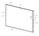
- FIG. 2 is a schematic perspective view of the liquid crystal module 1.
- the liquid crystal module 1 includes a horizontally long and rectangular liquid crystal panel 10.
- the liquid crystal panel 10 is made of a metal such as aluminum and stainless steel, for example, at the front peripheral edge and the peripheral side, and is covered with a front frame 11 that forms a frame.
- the front side frame 11 is composed of short rods 11a and 11a that are substantially the same as the length in the vertical direction on the short side of the liquid crystal panel 10, and long rods 11b and 11b that are substantially the same as the length in the horizontal direction on the long side. Composed.
- the front side frame 11 is fitted so that the bent portion is along the outer periphery of the liquid crystal panel 10, and covers the peripheral edge and the side surface of the front surface of the liquid crystal panel 10.
- a resin-made back side frame 12 is provided on the back side of the liquid crystal panel 10 and inside the front side frame 11.
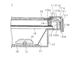
- FIG. 3 is a partial cross-sectional view of the liquid crystal module 1.
- FIG. 3 shows a cross section taken along line III-III in FIG.
- the liquid crystal module 1 includes a backlight chassis 13, a buffer material 14, an LED 15, an optical sheet 16, a diffusion plate 17, an LED substrate 18, and a lens 19 in addition to the liquid crystal panel 10, the front side frame 11, and the back side frame 12.
- the front frame 11 has an L shape with a cross section bent at a substantially right angle.
- rib holes 111, 111... are provided in the front frame 11 and ribs 121, 121. Further, the bent portion corresponding to the apex of the L-shaped cross section of the front side frame 11 is substantially linear along the length direction.
- the rib holes 111, 111... Are provided over the bent portion and the vicinity thereof, that is, the front side and the side of the front side frame 11.
- projecting portions 111a, 111a,... Projecting inward are provided on the front peripheral edge of the rib holes 111, 111,.
- the ribs 121, 121... Are fitted in the rib holes 111, 111.
- the back side frame 12 includes a side part 120a and an inner part 120b extending in the vertical direction of the liquid crystal panel 10, and a front part 120c extending in the vertical and horizontal directions.
- Buffer members 14 and 14 are provided in the vicinity of the front and rear edges of the liquid crystal panel 10, and the front side frame body 11 and the rear side frame body 12 are connected to the end of the liquid crystal panel 10 via the buffer members 14 and 14. It is comprised so that a part may be pinched
- a plurality of optical sheets 16, 16... For condensing the light of the LEDs 15, 15.
- the optical sheets 16, 16... are rectangular and have a slightly smaller area than the liquid crystal panel 10. Further, a cushioning material 14 is provided between the inside of the front part 120c and the optical sheets 16, 16,... And the front part 120c is adjusted to be substantially parallel to the liquid crystal panel 10.
- a diffusion plate 17 is provided on the back side of the optical sheets 16, 16.
- the diffusion plate 17 has a dish shape, and an end portion of the diffusion plate 17 is sandwiched between grooves formed by the side portion 120a and the inner portion 120b of the back frame 12.
- the diffusion plate 17 is covered with a backlight chassis 13 having a box shape.
- a plurality of LEDs 15, 15... are mounted on the front surface of the LED board 18 attached inside the backlight chassis 13, and a lens 19 that diffuses light emitted from the LEDs 15, 15. , 19... are arranged respectively.
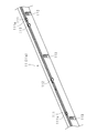
- FIG. 4 is a perspective view showing the short rod body 11a of the front side frame body 11
- FIG. 5 is a partial perspective view showing the short rod body 11a of the front side frame body 11. As shown in FIG.
- the front side frame 11 will be further described.
- the front side frame body 11 is provided with rib holes 111, 111..., Engagement holes 112, 112.
- the engagement holes 112, 112... are provided in the bent portion and the vicinity thereof, and are arranged in parallel with the rib holes 111, 111.
- Through holes 113 are formed in the side portions of the short rods 11a and 11a, respectively.
- a recess is provided around the through-holes 113, 113.
- the short rod body 11a is provided with three rib holes 111, 111, four engagement holes 112, 112, and five through holes 113, 113,.
- the rib holes 111, 111 ..., the engagement holes 112, 112 ..., the through holes 113, 113 ... are provided along the short rod body 11a at intervals from one end side to the other end side.
- One rib hole 111, 111... Is provided on the center side, one on one end side, and one on the other end side.
- Two engagement holes 112 are provided on the center side, one on one end side, and one on the other end side.
- the through holes 113, 113... Are provided at the center side, two at one end side, and two at the other end side.
- the rib hole 111 and the engagement hole 112 provided on one end side, and the rib hole 111 and the engagement hole 112 provided on the other end side are provided at positions close to each other.
- the interval between the rib hole 111 and the engagement hole 112 provided on one end side and the interval between the rib hole 111 and the engagement hole 112 provided on the other end side are the same as the rib hole 111 and the engagement provided at other positions. It is narrower than the interval between the holes 112, the interval between the rib holes 111, 111, and the interval between the engagement holes 112, 112.
- the rib hole 111 and the engagement hole 112 on one end side are provided between the two through holes 113 and 113 on the one end side.
- the rib hole 111 and the engagement hole 112 on the other end side are provided between the two through holes 113 and 113 on the other end side.
- a plurality of rib holes 111 and engaging holes 112 may be provided on one end side and the other end side of the short rod body 11a.
- the long rod 11b has the same shape as the short rod 11a except for the length in the longitudinal direction.
- the short rod body 11a and the long rod body 11b are fixed so as to be orthogonal to each other to form the front frame 11.
- FIG. 6 is a perspective view showing the short rod body 12a of the back frame 12.
- the back frame 12 is made of resin, and includes two long rods (not shown) that are substantially the same as the horizontal length of the liquid crystal panel 10, and two short rods 12 a that are substantially the same as the vertical length of the liquid crystal panel 10. It has a frame.
- the back frame 12 is provided with ribs 121, 121 ... and engaging claws 122, 122 ....
- the rib 121 is provided at the boundary between the side portion 120 a and the front portion 120 c and protrudes in the front direction perpendicular to the liquid crystal panel 10.
- engaging claws 122, 122... Are provided adjacent to the ribs 121, 121.
- the rib 121 has a rectangular shape and is provided at the boundary between the side portion 120a and the front portion 120c.
- the engaging claws 122, 122... Extend in the front direction perpendicular to the liquid crystal panel 10, and the engaging portions of the engaging claws 122, 122.
- the engaging claws 122, 122... Engage with the peripheral edges of the side portions 120a of the engaging holes 112, 112. Thereby, the shift
- the back side frame body 12 is provided with notches 123, 123... That are open from the vicinity of the center of the side portion 120a to the side end portion on the side portion 120a.
- the notches 123, 123... Are configured so that the screws pass when the screws pass through the through holes 113, 113. Note that through holes may be provided instead of the notches 123, 123.
- the ribs 121, 121 ..., the engaging claws 122, 122 ... and the through holes 113, 113 ... are located at the positions of the rib holes 111, 111 ..., the engaging holes 112, 112 ..., and the notches 123, 123, respectively. It corresponds.
- the rib 121 and the engaging claw 122 provided on one end side near the one end of the short rod 12a, and the rib 121 and the engaging claw 122 provided on the other end side near the other end are mutually connected. It is provided in the position close to.
- the distance between the rib 121 and the engaging claw 122 provided on one end side and the interval between the rib 121 and the engaging claw 122 provided on the other end side are the same as those of the rib 121 and the engaging claw 122 provided at other positions. It is narrower than the interval, the interval between the ribs 121, 121, and the interval between the engaging claws 122, 122.
- the rib 121 and the engaging claw 122 on one end side are provided between the two notches 123 and 123 on the one end side.
- the rib 121 and the engaging claw 122 on the other end side are provided between the two notches 123 and 123 on the other end side.
- a plurality of ribs 121 and engaging claws 122 may be provided on one end side and the other end side of the short rod body 12a.
- the long frame (not shown) of the back frame 12 has the same shape as the short frame 12a except for the length in the longitudinal direction.
- the short rod 12a and the long rod (not shown) are fixed so as to be orthogonal to each other to form the back side frame 12.
- FIG. 7 is a partial perspective view of the liquid crystal module 1 including the front side frame 11 and the back side frame 12.
- the front side frame body 11 and the back side frame body 12 are parallel to the liquid crystal panel 10. Can be reduced. Further, the protruding portion 111 a contacts the rib 121. This increases the contact area between the rib holes 111, 111... And the ribs 121, 121.
- the back frame 12 extends in a length direction substantially parallel to the side portion 120a, an inner portion 120b provided on the inner side of the side portion 120a, and parallel to the liquid crystal panel 10, and includes the side portion 120a and the side portion 120a.
- a front portion 120c connected to the inner side portion 120b.
- the short rod bodies 11a and 12a are rod bodies, they are easy to bend, and the influence when bent is smaller at the end side than at the center side. Therefore, when fixing the front side frame body 11 and the back side frame body 12, it can fix stably by fixing both ends.
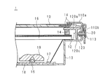
- FIG. 8 is a partial cross-sectional view of the liquid crystal module 1.
- FIG. 8 is a cross-sectional view of the cross section including the engagement hole 112 and the engagement claw 122.
- the engaging claw 122 may be another engaging member, and the engaging hole 112 may be any member that engages with the other engaging member.
- FIG. 9 is a partial cross-sectional view of the liquid crystal module 1.
- FIG. 9 is a cross-sectional view of a cross section including the through hole 113 and the notch 123.
- the fitting portion may be replaced with other fitting members other than the ribs 121, 121 ... instead of the ribs 121, 121 ..., and the fitted portion may be replaced with the rib holes 111, 111 ... A member fitted to another fitting member may be used. Further, the ribs 121, 121... And the engaging claws 122, 122... Are provided in the front side frame body 11, and the rib holes 111, 111. Good.
- the liquid crystal module 1 has a rectangular shape, a liquid crystal panel 10 that displays an image on the front surface, a back frame 12 provided on the back side of the liquid crystal panel 10, and a front peripheral edge of the liquid crystal panel 10.
- the liquid crystal module 1 including the front side frame body 11 that covers the liquid crystal panel 10 by covering the liquid crystal panel 10 by connecting to the back side frame body 12 and covering the front side and peripheral side parts.
- One of them is an engaging portion that fixes a position in a direction perpendicular to the liquid crystal panel 10 by engaging, and a fitting portion that fixes a position in a direction parallel to the liquid crystal panel 10 by fitting.
- the other of the front side frame body 11 and the back side frame body 12 is provided with an engaged portion with which the engaging portion engages and a fitted portion with which the fitting portion is fitted. It is characterized by that.
- one of the front side frame body 11 and the back side frame body 12 is engaged with the engaging portion that fixes the position in the direction perpendicular to the liquid crystal panel 10 by engagement, and the fitting
- a fitting portion for fixing the position in the direction parallel to the liquid crystal panel 10 is provided, and on the other side, an engaged portion and a fitted portion are provided.
- the front-side frame body 11 and the back-side frame body 12 have a rectangular shape, and the engagement portion and the fitting portion are at least the front-side frame body 11 or the back surface.
- the engaged portion and the fitted portion constitute at least the front side frame body 11 or the back side frame body 12. It is characterized by being provided close to each other in the vicinity of both ends of the side and corresponding to the engaging portion and the fitting portion.
- the engaged portion is an engagement hole 112 provided over the front side surface and the side surface side of the front frame 11, and the engagement portion is
- the engaging claw 122 is provided on the back frame 12 and extends in a direction perpendicular to the liquid crystal panel 10 and engages with a peripheral edge on the side surface side of the engaging hole 112.
- the positions of the front side frame body 11 and the back side frame body 12 can be fixed by engaging the engagement holes 112 with the engagement claws 122.
- the fitted portion is a fitting hole provided over the front side surface and the side surface side of the front side frame body 11, and the fitting portion is formed on the back surface.
- the rib 121 is provided on the side frame 12 and protrudes in a direction perpendicular to the liquid crystal panel 10.
- the positions of the front side frame body 11 and the back side frame body 12 can be fixed by fitting the ribs 121 into the fitting holes.
- the liquid crystal module 1 according to the present invention is characterized in that a protrusion 111a that contacts the rib 121 at the time of fitting is provided at the periphery of the fitting hole.
- the protrusion 111a is provided, so that the positions of the fitting hole and the rib 121 can be fixed with high accuracy.
- the display device 100 includes the liquid crystal module 1 described above.
- the above-described effects can be realized in the display device 100.
- the television receiver includes the above-described liquid crystal module 1 and a tuner that receives a television broadcast. Based on the television broadcast received by the tuner, an image is displayed on the liquid crystal module 1. It is characterized by being displayed.
- the above-described effects can be realized in the television receiver.
Landscapes
- Physics & Mathematics (AREA)
- Nonlinear Science (AREA)
- Mathematical Physics (AREA)
- Chemical & Material Sciences (AREA)
- Crystallography & Structural Chemistry (AREA)
- General Physics & Mathematics (AREA)
- Optics & Photonics (AREA)
- Liquid Crystal (AREA)
- Devices For Indicating Variable Information By Combining Individual Elements (AREA)
Abstract
薄型化及び軽量化を実現する液晶モジュールを提供する。矩形状をなし、前面に画像を表示する液晶パネルと、該液晶パネルの背面側に設けられた背面側枠体12と、前記液晶パネルの前側周縁部及び周側部を覆い、前記背面側枠体12と接続することにより前記液晶パネルを挟む前面側枠体とを備える液晶モジュールにおいて、前記前面側枠体及び背面側枠体12の一方には、係合することにより前記液晶パネルに垂直な方向の位置を固定する係合部、及び嵌合することにより前記液晶パネルに平行な方向の位置を固定する嵌合部が設けられ、前記前面側枠体及び背面側枠体12の他方には、前記係合部が係合する被係合部及び前記嵌合部が嵌合する被嵌合部が設けられている。
Description
本発明は、液晶パネルを枠体で固定する液晶モジュール及び表示装置に関する。
液晶パネルを備えた表示装置は、薄型化及び軽量化が要請されており、その要請に伴い、液晶パネルの周囲に設けられ、前面及び背面側に取り付けられた枠体ともに薄型化及び軽量化が望まれている。ここで、薄型化、軽量化のため背面側の枠体が薄くなり、背面側枠体自体での強度が低下するという問題があった。
特許文献1には、液晶パネルを前面側に設けられた前面側枠体と背面側に設けられた背面側枠体とにより挟んでビスで留め、光源及びバックシャーシ等を備えた液晶モジュール及び表示装置が記載されている。
しかしながら、特許文献1に記載の液晶モジュール及び表示装置は、ビスによって前面側枠体と背面側枠体とを液晶パネルで挟んで固定しているので、前面側枠体と背面側枠体とにビスの長さ及び螺子頭の大きさに応じた幅又は厚みが必要になるという問題があった。また、斯かる液晶モジュール及び表示装置では十数センチ間隔でビス固定する場合もあり、50インチ以上の大型パネルの場合にはビスの数も30個以上になり、生産工数が増加するという問題があった。
本発明は斯かる事情に鑑みてなされたものであり、斯かる前面側枠体と背面側枠体の薄型化及び軽量化を実現しつつ、液晶パネルの位置を固定する液晶モジュール及び表示装置を提供することを目的とする。また、前面側枠体、背面側枠体間を固定するビスを大幅に削減した液晶モジュール及び表示装置を提供することを目的とする。
本発明に係る液晶モジュールは、矩形状をなし、前面に画像を表示する液晶パネルと、該液晶パネルの背面側に設けられた背面側枠体と、前記液晶パネルの前側周縁部及び周側部を覆い、前記背面側枠体と接続することにより前記液晶パネルを挟む前面側枠体とを備える液晶モジュールにおいて、前記前面側枠体及び背面側枠体の一方には、係合することにより前記液晶パネルに垂直な方向の位置を固定する係合部、及び嵌合することにより前記液晶パネルに平行な方向の位置を固定する嵌合部が設けられ、前記前面側枠体及び背面側枠体の他方には、前記係合部が係合する被係合部及び前記嵌合部が嵌合する被嵌合部が設けられていることを特徴とする。
本発明に係る液晶モジュールは、前記前面側枠体及び背面側枠体は矩形状をなしており、前記係合部及び嵌合部は、少なくとも前記前面側枠体又は背面側枠体を構成する辺の両端夫々の近傍で相互に近接する位置に設けられ、前記被係合部及び被嵌合部は、少なくとも前記前面側枠体又は背面側枠体を構成する辺の両端夫々の近傍で相互に近接し、前記係合部及び嵌合部に対応する位置に設けられていることを特徴とする。
本発明に係る液晶モジュールは、前記被係合部は、前記前面側枠体の前面側及び側面側に渡って設けられた係合孔であり、前記係合部は、前記背面側枠体に設けられ、前記液晶パネルに垂直な方向に延びており、前記係合孔における側面側の周縁に係合する係合爪であることを特徴とする。
本発明に係る液晶モジュールは、前記被嵌合部は、前記前面側枠体の前面側及び側面側に渡って設けられた嵌合孔であり、前記嵌合部は、前記背面側枠体に設けられ、前記液晶パネルに垂直な方向に突出したリブであることを特徴とする。
本発明に係る液晶モジュールは、前記嵌合孔の周縁には、嵌合時に前記リブと接触する突出部が設けられていることを特徴とする。
本発明に係る表示装置は、上述の液晶モジュールを備えることを特徴とする。
本発明に係るテレビジョン受信機は、上述の液晶モジュールと、テレビジョン放送を受信するチューナとを備え、該チューナにて受信したテレビジョン放送に基づいて、前記液晶モジュールに映像を表示するようにしてあることを特徴とする。
本発明によれば、前記前面側枠体及び背面側枠体の一方には、係合することにより前記液晶パネルに垂直な方向の位置を固定する係合部、及び嵌合することにより前記液晶パネルに平行な方向の位置を固定する嵌合部が設けられ、他方には、被係合部及び被嵌合部が設けられているので、枠体の薄型化及び軽量化を実現することができる。
また、前面側枠体及び背面側枠体間を固定するビスを大幅に削減したので、生産時の作業性を向上させることができる。
以下、本発明の実施の形態について説明する。図1は表示装置100の模式的斜視図である。表示装置100は、液晶モジュール1と、該液晶モジュール1を挾むようにして収容するフロントキャビネット2及びバックキャビネット3と、電源基板4と、チューナを備えるチューナ基板5と、スタンド6とを備える。表示装置100は、チューナ基板5のチューナより受信したテレビジョン放送に基づいて、前記液晶モジュール1に映像を表示するテレビジョン受信機として機能する。
図2は液晶モジュール1の模式的斜視図である。液晶モジュール1は、横長で矩形板状の液晶パネル10を備える。液晶パネル10は、前側周縁部及び周側部を、例えばアルミニウム、ステンレス等の金属製であり、枠体をなす前面側枠体11により覆われている。前面側枠体11は、液晶パネル10の短辺側である縦方向の長さと略同じ短竿体11a、11aと、長辺側である横方向の長さと略同じ長竿体11b、11bとにより構成される。前面側枠体11は、屈曲部が液晶パネル10の外周と沿うように嵌合し、液晶パネル10の前面の周縁と側面とを覆う。また、液晶パネル10の背面側であり前面側枠体11の内側に、樹脂製の背面側枠体12が設けられている。
図3は液晶モジュール1の部分断面図である。図3は図2のIII-IIIに沿った断面を示したものである。液晶モジュール1は、液晶パネル10、前面側枠体11、背面側枠体12の他に、バックライトシャーシ13、緩衝材14、LED15、光学シート16、拡散板17、LED基板18及びレンズ19を備える。前面側枠体11は断面が略直角に曲がったL字状をなしている。
III-III線上には前面側枠体11にリブ孔111、111…、背面側枠体12にリブ121、121…が設けられている。また、前面側枠体11におけるL字状の断面の頂点にあたる屈曲部は、長さ方向に沿って略直線状をなしている。リブ孔111、111…は、屈曲部及びその近傍、即ち前面側枠体11の前面側及び側面側に渡って設けられている。またリブ孔111、111…の前方側の周縁には、内側に突出した突出部111a、111a…が設けられている。リブ121、121…はリブ孔111、111…に嵌合している。
背面側枠体12は、液晶パネル10の垂直方向に延びる側部120a及び内側部120bと、縦横方向に延びる前部120cとを備える。
液晶パネル10の前面及び背面の周縁付近には、緩衝材14、14が設けられており、前面側枠体11と背面側枠体12は緩衝材14、14を介して、液晶パネル10の端部を挟むよう構成されている。
液晶パネル10の背面側には、並設されたLED15、15…の光を液晶パネル10に向けて集光する光学シート16、16…が複数設けられている。光学シート16、16…は、矩形状をなし、液晶パネル10よりやや小さい面積を有する。また、前部120cの内側と光学シート16、16…との間には緩衝材14が設けられており、前部120cが液晶パネル10と略平行になるよう調整されている。
光学シート16、16…の背面側にはLED15、15…の光を均一に拡散する拡散板17が設けられている。拡散板17は皿状をなし、該拡散板17の端部は背面側枠体12の側部120aと内側部120bとにより構成される溝に挟まれている。
拡散板17は、箱状をなすバックライトシャーシ13に覆われている。バックライトシャーシ13の内部に取り付けられたLED基板18の前面には、複数のLED15、15…が実装されており、LED15、15…の前方に、LED15、15…から発する光を拡散させるレンズ19、19…が夫々配置されている。
図4は、前面側枠体11の短竿体11aを示す斜視図であり、図5は、前面側枠体11の短竿体11aを示す部分斜視図である。
前面側枠体11についてさらに説明する。前面側枠体11には、リブ孔111、111…、係合孔112、112…、貫通孔113、113…が設けられている。
係合孔112、112…は、屈曲部及びその近傍に設けられており、リブ孔111、111…と並設されている。短竿体11a、11aの側部には、夫々に貫通孔113、113…が設けられている。貫通孔113、113…の周辺は凹みが設けられている。例えば短竿体11aには、リブ孔111、111…が3個、係合孔112、112…が4個、貫通孔113、113…が5個設けられている。
リブ孔111、111…、係合孔112、112…、貫通孔113、113…は、短竿体11aに沿って、一端側から他端側まで間隔を置いて設けられている。リブ孔111、111…は、中央側に1つ、一端側に1つ、他端側に1つ設けられている。係合孔112、112…は、中央側に2つ、一端側に1つ、他端側に1つ設けられている。貫通孔113、113…は、中央側に1つ、一端側に2つ、他端側に2つ設けられている。
一端側に設けられたリブ孔111及び係合孔112、並びに他端側に設けられたリブ孔111及び係合孔112は、相互に近接した位置に設けられている。一端側に設けられたリブ孔111及び係合孔112の間隔、並びに他端側に設けられたリブ孔111及び係合孔112の間隔は、その他の位置に設けられたリブ孔111及び係合孔112の間隔、並びにリブ孔111、111同士の間隔及び係合孔112、112同士の間隔よりも狭い。
また、一端側におけるリブ孔111及び係合孔112は、一端側における2つの貫通孔113、113の間に設けられている。同様に、他端側におけるリブ孔111及び係合孔112は、他端側における2つの貫通孔113、113の間に設けられている。なお、リブ孔111及び係合孔112は、短竿体11aの一端側及び他端側に夫々複数設けられていてもよい。
長竿体11bも長手方向の長さを除き、短竿体11aと同様の形状である。短竿体11aと長竿体11bとは直交するよう固定されて前面側枠体11を形成する。
図6は、背面側枠体12の短竿体12aを示す斜視図である。背面側枠体12は樹脂製であり、液晶パネル10の水平方向の長さと略同じ2本の図示しない長竿体と、液晶パネル10の縦方向の長さと略同じ2本の短竿体12aとにより枠体をなしている。
該背面側枠体12には、リブ121、121…及び係合爪122、122…が設けられている。リブ121は、側部120aと前部120cとの境界に設けられており、液晶パネル10と垂直な前方向に突出している。また、リブ121、121…に隣接して係合爪122、122…が設けられている。リブ121は矩形状をなし、側部120aと前部120cの境界に設けられている。係合爪122、122…は、液晶パネル10と垂直な前方向に延びており、また、係合爪122、122…の係合部分は背面側枠体12の外側を向いている。係合爪122、122…は、係合孔112、112…の側部120aの周縁に係合する。これにより液晶パネル10に垂直な方向のずれを抑制することができる。
背面側枠体12には、側部120aに、該側部120aの中央付近から、側端部まで空いた切り欠き部123、123…が設けられている。切り欠き部123、123…は、前面側枠体11の貫通孔113、113…を螺子が通じた場合に螺子が通るようになっている。なお、切り欠き部123、123…の代わりに貫通孔が設けられていてもよい。
リブ121、121…、係合爪122、122…及び貫通孔113、113…の位置は、夫々リブ孔111、111…、係合孔112、112…及び切り欠き部123、123…の位置に対応している。
従って、短竿体12aの一端の近傍である一端側に設けられたリブ121及び係合爪122、並びに他端の近傍である他端側に設けられたリブ121及び係合爪122は、相互に近接した位置に設けられている。一端側に設けられたリブ121及び係合爪122の間隔、並びに他端側に設けられたリブ121及び係合爪122の間隔は、その他の位置に設けられたリブ121及び係合爪122の間隔、並びにリブ121、121同士の間隔及び係合爪122、122同士の間隔よりも狭い。
また、一端側におけるリブ121及び係合爪122は、一端側における2つの切り欠き部123、123の間に設けられている。同様に、他端側におけるリブ121及び係合爪122は、他端側における2つの切り欠き部123、123の間に設けられている。なお、リブ121及び係合爪122は、短竿体12aの一端側及び他端側に夫々複数設けられていてもよい。
背面側枠体12の図示しない長竿体も長手方向の長さを除き、短竿体12aと同様の形状である。短竿体12aと図示しない長竿体とは直交するよう固定されて背面側枠体12を形成する。
図7は、前面側枠体11及び背面側枠体12を含む液晶モジュール1の部分斜視図である。
嵌合部であるリブ121、121…を被嵌合部であるリブ孔111、111…に嵌合することにより、前面側枠体11及び背面側枠体12の液晶パネル10と平行な方向へのずれを低減させることができる。また、突出部111aはリブ121と接触する。これによりリブ孔111、111…とリブ121、121…との接触面積が増え、位置のずれを効果的に抑制する。
また、係合爪122を係合孔112に係合することにより、前面側枠体11及び背面側枠体12の横方向へのずれを低減させることができる。また、背面側枠体12には、側部120aと略平行に長さ方向に延びており、側部120aより内側に設けられた内側部120bと、液晶パネル10に平行であり側部120a及び内側部120bと繋がっている前部120cとを備える。
このように、リブ孔111、111…にリブ121、121…を嵌合させ、係合孔112、112…に係合爪122、122…を係合させ、さらに貫通孔113、113…にビス20を通じることにより、液晶モジュール1に対する前面側枠体11及び背面側枠体12の位置を固定する。
短竿体11a、12aは、竿体であることから曲がりやすく、曲がった場合の影響は端側の方が中央側よりも小さい。そのため、前面側枠体11と背面側枠体12とを固定する際には、両端側を固定することにより安定して固定することができる。
以上より、リブ孔111、111…及び係合孔112、112…、並びにリブ121、121…及び係合爪122、122…を、前面側枠体11及び背面側枠体12の一辺を構成する短竿体11a、12aの両端側にも設けることにより、前面側枠体11及び背面側枠体12の位置を固定するにあたり、容易かつ適切に固定することができる。
図8は、液晶モジュール1の部分断面図である。図8は係合孔112及び係合爪122を含む断面の断面図である。なお、係合爪122は他の係合部材でもよく、係合孔112は該他の係合部材を係合するものであればよい。
図9は、液晶モジュール1の部分断面図である。図9は貫通孔113及び切り欠き部123を含む断面の断面図である。
なお、嵌合部は、リブ121、121…に代えて、リブ121、121…以外の他の嵌合部材を用いてもよく、被嵌合部は、リブ孔111、111…に代えて該他の嵌合部材に嵌合される部材を用いてもよい。さらに、リブ121、121…及び係合爪122、122…を前面側枠体11に備え、リブ孔111、111…及び係合孔112、112…を背面側枠体12に備えるようにしてもよい。
本発明に係る液晶モジュール1は、矩形状をなし、前面に画像を表示する液晶パネル10と、該液晶パネル10の背面側に設けられた背面側枠体12と、前記液晶パネル10の前側周縁部及び周側部を覆い、前記背面側枠体12と接続することにより前記液晶パネル10を挟む前面側枠体11とを備える液晶モジュール1において、前記前面側枠体11及び背面側枠体12の一方には、係合することにより前記液晶パネル10に垂直な方向の位置を固定する係合部、及び嵌合することにより前記液晶パネル10に平行な方向の位置を固定する嵌合部が設けられ、前記前面側枠体11及び背面側枠体12の他方には、前記係合部が係合する被係合部及び前記嵌合部が嵌合する被嵌合部が設けられていることを特徴とする。
本実施の形態によれば、前記前面側枠体11及び背面側枠体12の一方には、係合することにより前記液晶パネル10に垂直な方向の位置を固定する係合部、及び嵌合することにより前記液晶パネル10に平行な方向の位置を固定する嵌合部が設けられ、他方には、被係合部及び被嵌合部が設けられているので、枠体の薄型化及び軽量化を実現することができる。
本実施の形態に係る液晶モジュール1は、前記前面側枠体11及び背面側枠体12は矩形状をなしており、前記係合部及び嵌合部は、少なくとも前記前面側枠体11又は背面側枠体12を構成する辺の両端夫々の近傍で相互に近接する位置に設けられ、前記被係合部及び被嵌合部は、少なくとも前記前面側枠体11又は背面側枠体12を構成する辺の両端夫々の近傍で相互に近接し、前記係合部及び嵌合部に対応する位置に設けられていることを特徴とする。
本実施の形態によれば、前面側枠体11及び背面側枠体12の位置を固定するにあたり、容易かつ適切に固定することができる。
本実施の形態に係る液晶モジュール1は、前記被係合部は、前記前面側枠体11の前面側及び側面側に渡って設けられた係合孔112であり、前記係合部は、前記背面側枠体12に設けられ、前記液晶パネル10に垂直な方向に延びており、前記係合孔112における側面側の周縁に係合する係合爪122であることを特徴とする。
本実施の形態によれば、係合孔112を係合爪122によって係合することにより、前面側枠体11及び背面側枠体12の位置を固定することができる。
本実施の形態に係る液晶モジュール1は、前記被嵌合部は、前記前面側枠体11の前面側及び側面側に渡って設けられた嵌合孔であり、前記嵌合部は、前記背面側枠体12に設けられ、前記液晶パネル10に垂直な方向に突出したリブ121であることを特徴とする。
本実施の形態によれば、嵌合孔にリブ121が嵌合することにより、前面側枠体11及び背面側枠体12の位置を固定することができる。
本発明に係る液晶モジュール1は、前記嵌合孔の周縁には、嵌合時に前記リブ121と接触する突出部111aが設けられていることを特徴とする。
本実施の形態によれば、突出部111aが設けられていることにより、嵌合孔とリブ121との位置を精度よく固定することができる。
本実施の形態に係る表示装置100は、上述の液晶モジュール1を備えることを特徴とする。
本実施の形態によれば、上述の効果を表示装置100において実現することができる。
本実施の形態に係るテレビジョン受信機は、上述の液晶モジュール1と、テレビジョン放送を受信するチューナとを備え、該チューナにて受信したテレビジョン放送に基づいて、前記液晶モジュール1に映像を表示するようにしてあることを特徴とする。
本実施の形態によれば、上述の効果をテレビジョン受信機において実現することができる。
今回開示された実施の形態はすべての点で例示であって、制限的なものでは無いと考えられるべきである。本発明の範囲は、上記した意味では無く、特許請求の範囲によって示され、特許請求の範囲と均等の意味及び範囲内でのすべての変更が含まれることが意図される。
100 表示装置
1 液晶モジュール
2 フロントキャビネット
3 バックキャビネット
4 電源基板
5 チューナ基板
6 スタンド
10 液晶パネル
11 前面側枠体
11a 短竿体
11b 長竿体
111 リブ孔
112 係合孔
113 貫通孔
12 背面側枠体
12a 短竿体
120a 側部
120b 内側部
120c 前部
121 リブ
122 係合爪
123 切り欠き部
13 バックライトシャーシ
14 緩衝材
15 LED
16 光学シート
17 拡散板
18 LED基板
19 レンズ
20 ビス
1 液晶モジュール
2 フロントキャビネット
3 バックキャビネット
4 電源基板
5 チューナ基板
6 スタンド
10 液晶パネル
11 前面側枠体
11a 短竿体
11b 長竿体
111 リブ孔
112 係合孔
113 貫通孔
12 背面側枠体
12a 短竿体
120a 側部
120b 内側部
120c 前部
121 リブ
122 係合爪
123 切り欠き部
13 バックライトシャーシ
14 緩衝材
15 LED
16 光学シート
17 拡散板
18 LED基板
19 レンズ
20 ビス
Claims (6)
- 矩形状をなし、前面に画像を表示する液晶パネルと、
該液晶パネルの背面側に設けられた背面側枠体と、
前記液晶パネルの前側周縁部及び周側部を覆い、前記背面側枠体と接続することにより前記液晶パネルを挟む前面側枠体と
を備える液晶モジュールにおいて、
前記前面側枠体及び背面側枠体の一方には、係合することにより前記液晶パネルに垂直な方向の位置を固定する係合部、及び嵌合することにより前記液晶パネルに平行な方向の位置を固定する嵌合部が設けられ、
前記前面側枠体及び背面側枠体の他方には、前記係合部が係合する被係合部及び前記嵌合部が嵌合する被嵌合部が設けられている
ことを特徴とする液晶モジュール。 - 前記前面側枠体及び背面側枠体は矩形状をなしており、
前記係合部及び嵌合部は、少なくとも前記前面側枠体又は背面側枠体を構成する辺の両端夫々の近傍で相互に近接する位置に設けられ、
前記被係合部及び被嵌合部は、少なくとも前記前面側枠体又は背面側枠体を構成する辺の両端夫々の近傍で相互に近接し、前記係合部及び嵌合部に対応する位置に設けられている
ことを特徴とする請求項1に記載の液晶モジュール。 - 前記被係合部は、前記前面側枠体の前面側及び側面側に渡って設けられた係合孔であり、
前記係合部は、前記背面側枠体に設けられ、前記液晶パネルに垂直な方向に延びており、前記係合孔における側面側の周縁に係合する係合爪である
ことを特徴とする請求項1又は2に記載の液晶モジュール。 - 前記被嵌合部は、前記前面側枠体の前面側及び側面側に渡って設けられた嵌合孔であり、
前記嵌合部は、前記背面側枠体に設けられ、前記液晶パネルに垂直な方向に突出したリブである
ことを特徴とする請求項1から3までのいずれか一つに記載の液晶モジュール。 - 前記嵌合孔の周縁には、嵌合時に前記リブと接触する突出部が設けられている
ことを特徴とする請求項4に記載の液晶モジュール。 - 請求項1から5のいずれか一つに記載の液晶モジュール
を備えることを特徴とする表示装置。
Applications Claiming Priority (4)
| Application Number | Priority Date | Filing Date | Title |
|---|---|---|---|
| JP2013-020522 | 2013-02-05 | ||
| JP2013020522 | 2013-02-05 | ||
| JP2014017710A JP2014170224A (ja) | 2013-02-05 | 2014-01-31 | 液晶モジュール及び表示装置 |
| JP2014-017710 | 2014-01-31 |
Publications (1)
| Publication Number | Publication Date |
|---|---|
| WO2014123099A1 true WO2014123099A1 (ja) | 2014-08-14 |
Family
ID=51299693
Family Applications (1)
| Application Number | Title | Priority Date | Filing Date |
|---|---|---|---|
| PCT/JP2014/052517 Ceased WO2014123099A1 (ja) | 2013-02-05 | 2014-02-04 | 液晶モジュール及び表示装置 |
Country Status (2)
| Country | Link |
|---|---|
| JP (1) | JP2014170224A (ja) |
| WO (1) | WO2014123099A1 (ja) |
Citations (8)
| Publication number | Priority date | Publication date | Assignee | Title |
|---|---|---|---|---|
| JPH09197383A (ja) * | 1996-01-22 | 1997-07-31 | Casio Comput Co Ltd | 液晶表示装置 |
| JPH11242447A (ja) * | 1997-12-25 | 1999-09-07 | Sanyo Electric Co Ltd | 液晶表示装置 |
| JPH11272194A (ja) * | 1998-03-20 | 1999-10-08 | Alps Electric Co Ltd | 液晶表示装置 |
| JPH11282360A (ja) * | 1998-03-30 | 1999-10-15 | Alps Electric Co Ltd | 液晶表示装置 |
| JP2003346533A (ja) * | 2002-05-29 | 2003-12-05 | Samsung Electronics Co Ltd | バックライトアセンブリ及びこれを有する液晶表示装置 |
| JP2005121929A (ja) * | 2003-10-17 | 2005-05-12 | Sony Corp | 液晶表示装置 |
| JP2007286396A (ja) * | 2006-04-18 | 2007-11-01 | Mitsubishi Electric Corp | 液晶表示装置 |
| WO2011125628A1 (ja) * | 2010-04-01 | 2011-10-13 | シャープ株式会社 | 表示装置 |
Family Cites Families (6)
| Publication number | Priority date | Publication date | Assignee | Title |
|---|---|---|---|---|
| US7948572B2 (en) * | 2006-07-21 | 2011-05-24 | Samsung Electronics Co., Ltd. | Hollow mold for receiving liquid crystal panel and diffuser plate and liquid crystal display including hollow mold |
| TWM314868U (en) * | 2006-11-27 | 2007-07-01 | Innolux Display Corp | Backlight module and liquid crystal display using same |
| JP5082638B2 (ja) * | 2007-07-11 | 2012-11-28 | 船井電機株式会社 | 液晶表示装置 |
| JP2009162922A (ja) * | 2007-12-28 | 2009-07-23 | Orion Denki Kk | 液晶表示パネル |
| KR101621540B1 (ko) * | 2009-09-17 | 2016-05-31 | 엘지디스플레이 주식회사 | 액정표시장치 |
| JP2011128557A (ja) * | 2009-12-21 | 2011-06-30 | Funai Electric Co Ltd | 液晶モジュール及び液晶モジュールのベゼル取り付け構造 |
-
2014
- 2014-01-31 JP JP2014017710A patent/JP2014170224A/ja active Pending
- 2014-02-04 WO PCT/JP2014/052517 patent/WO2014123099A1/ja not_active Ceased
Patent Citations (8)
| Publication number | Priority date | Publication date | Assignee | Title |
|---|---|---|---|---|
| JPH09197383A (ja) * | 1996-01-22 | 1997-07-31 | Casio Comput Co Ltd | 液晶表示装置 |
| JPH11242447A (ja) * | 1997-12-25 | 1999-09-07 | Sanyo Electric Co Ltd | 液晶表示装置 |
| JPH11272194A (ja) * | 1998-03-20 | 1999-10-08 | Alps Electric Co Ltd | 液晶表示装置 |
| JPH11282360A (ja) * | 1998-03-30 | 1999-10-15 | Alps Electric Co Ltd | 液晶表示装置 |
| JP2003346533A (ja) * | 2002-05-29 | 2003-12-05 | Samsung Electronics Co Ltd | バックライトアセンブリ及びこれを有する液晶表示装置 |
| JP2005121929A (ja) * | 2003-10-17 | 2005-05-12 | Sony Corp | 液晶表示装置 |
| JP2007286396A (ja) * | 2006-04-18 | 2007-11-01 | Mitsubishi Electric Corp | 液晶表示装置 |
| WO2011125628A1 (ja) * | 2010-04-01 | 2011-10-13 | シャープ株式会社 | 表示装置 |
Also Published As
| Publication number | Publication date |
|---|---|
| JP2014170224A (ja) | 2014-09-18 |
Similar Documents
| Publication | Publication Date | Title |
|---|---|---|
| JP6267936B2 (ja) | 曲面ディスプレイ装置 | |
| US9128326B2 (en) | Supporting member for backlight unit, backlight unit and image display apparatus having the same | |
| JP5508478B2 (ja) | 表示装置及びテレビジョン受信機 | |
| JP2012037672A (ja) | 表示装置 | |
| US20150177527A1 (en) | Apparatus for displaying three-dimensional image | |
| US20150346541A1 (en) | Display device | |
| US9507078B2 (en) | Black light module with mount and displaying apparatus therewith | |
| US10302851B2 (en) | Display apparatus | |
| US9319621B2 (en) | Display apparatus and television receiver | |
| US9684123B2 (en) | Display device and television receiver | |
| US10036908B2 (en) | Medical monitor, electronic apparatus, and video display unit | |
| JP6453896B2 (ja) | 表示装置 | |
| KR20140091834A (ko) | 백라이트 모듈 및 이를 포함하는 표시 장치 | |
| US20140118994A1 (en) | Display module and display apparatus having the same | |
| WO2014069456A1 (ja) | 表示装置 | |
| WO2014123099A1 (ja) | 液晶モジュール及び表示装置 | |
| CN104321583B (zh) | 照明装置、显示装置以及电视接收装置 | |
| JP6475782B2 (ja) | 表示装置およびテレビジョン受信機 | |
| US9958600B2 (en) | Light-source device and display apparatus | |
| JP2015232651A (ja) | 画像表示装置 | |
| JP2013130829A (ja) | 表示装置及びテレビ受信装置 | |
| JP3172830U (ja) | 広告装置、押縁、および板状部材の固定構造 | |
| WO2016013546A1 (ja) | 表示装置及びテレビジョン受信機 | |
| JP6377966B2 (ja) | 表示装置、及びテレビジョン受信機 | |
| KR20160077414A (ko) | 표시장치 |
Legal Events
| Date | Code | Title | Description |
|---|---|---|---|
| 121 | Ep: the epo has been informed by wipo that ep was designated in this application |
Ref document number: 14748772 Country of ref document: EP Kind code of ref document: A1 |
|
| NENP | Non-entry into the national phase |
Ref country code: DE |
|
| 122 | Ep: pct application non-entry in european phase |
Ref document number: 14748772 Country of ref document: EP Kind code of ref document: A1 |