WO2014122775A1 - プレス機械のスライドロック装置 - Google Patents
プレス機械のスライドロック装置 Download PDFInfo
- Publication number
- WO2014122775A1 WO2014122775A1 PCT/JP2013/053068 JP2013053068W WO2014122775A1 WO 2014122775 A1 WO2014122775 A1 WO 2014122775A1 JP 2013053068 W JP2013053068 W JP 2013053068W WO 2014122775 A1 WO2014122775 A1 WO 2014122775A1
- Authority
- WO
- WIPO (PCT)
- Prior art keywords
- lock
- pin members
- press machine
- pin
- slide
- Prior art date
Links
Images


Classifications
-
- B—PERFORMING OPERATIONS; TRANSPORTING
- B30—PRESSES
- B30B—PRESSES IN GENERAL
- B30B15/00—Details of, or accessories for, presses; Auxiliary measures in connection with pressing
- B30B15/28—Arrangements for preventing distortion of, or damage to, presses or parts thereof
-
- B—PERFORMING OPERATIONS; TRANSPORTING
- B30—PRESSES
- B30B—PRESSES IN GENERAL
- B30B15/00—Details of, or accessories for, presses; Auxiliary measures in connection with pressing
- B30B15/28—Arrangements for preventing distortion of, or damage to, presses or parts thereof
- B30B15/287—Arrangements for preventing distortion of, or damage to, presses or parts thereof preventing unintended ram movement, e.g. using blocking devices
-
- Y—GENERAL TAGGING OF NEW TECHNOLOGICAL DEVELOPMENTS; GENERAL TAGGING OF CROSS-SECTIONAL TECHNOLOGIES SPANNING OVER SEVERAL SECTIONS OF THE IPC; TECHNICAL SUBJECTS COVERED BY FORMER USPC CROSS-REFERENCE ART COLLECTIONS [XRACs] AND DIGESTS
- Y10—TECHNICAL SUBJECTS COVERED BY FORMER USPC
- Y10T—TECHNICAL SUBJECTS COVERED BY FORMER US CLASSIFICATION
- Y10T74/00—Machine element or mechanism
- Y10T74/20—Control lever and linkage systems
- Y10T74/20576—Elements
- Y10T74/20636—Detents
Definitions
- the present invention relates to a slide lock device for a press machine that can stop the slide of the press machine at a desired stop position or a position near the stop position.
- the slide lock device of the servo press disclosed in Patent Document 1 can lock the helical gear at an arbitrary position by engaging the engaging claw with the gear teeth of a large-diameter helical gear that drives the slide up and down via an eccentric mechanism. It is a slide lock device.
- this slide lock device three sets of lock units are provided side by side in the helical gear tooth width direction, and an engagement claw that can be engaged with a valley between the gear teeth of the helical gear is provided on the lower end side of the lock unit.
- the claw is driven forward and backward by a hydraulic actuator provided in the lock unit.
- the three lock units are driven simultaneously to drive the three engaging claws to the advancing side, and any one engaging claw is engaged with the valley between the gear teeth,
- the engaging claw With the ball lock mechanism including, the helical gear is locked and the slide is locked.
- Patent Document 2 discloses a safety lock mechanism such as a press.
- a stationary member that penetrates a shaft member of a press is fixed to a main body frame, and a plurality of lock pins are movably mounted in a plurality of holding holes formed in the stationary member.
- a locked member facing the stationary member from the outside in the axial direction is fixed to the shaft member, and a plurality of arc-shaped recesses for receiving inner halves of a plurality of lock pins are provided in the vicinity of the outer periphery of the locked member.
- a plurality of locking teeth that can receive the lock pin are formed at the circumferential ends of the recesses.
- ⁇ A compression spring that urges each of the plurality of lock pins to the advanced position is attached to the holding hole.
- each of a plurality of lock pins among the plurality of lock pins is introduced into one of the recesses, and then receives the locking tooth at the end of the recess.
- the locked member is locked so as not to rotate with the plurality of lock pins, the shaft member is locked so as not to rotate, and the slide is locked.
- annular fluid pressure cylinder is provided on the opposite side of the stationary member with respect to the locked member, and the annular piston of this fluid pressure cylinder has an axial center on the outer half of all the lock pins. It faces from the outside in the direction.
- the annular piston When the shaft member and the slide are held in the locked state, the annular piston is held in the retracted position, and when held in the unlocked state, the annular piston is driven to the advanced position, and the whole is held by the annular piston.
- the half of the outer periphery of the lock pin is pressed toward the holding hole, and all the lock pins are switched to the retracted position separated from the recess to hold the state.
- the lock pin is cantilevered by the holding hole in the locked state, which is disadvantageous in ensuring the durability of the lock pin and the holding hole. .
- An object of the present invention is to provide a highly reliable slide lock device for a press machine in which a plurality of pin members can be locked at an advanced position and a retracted position, a slide lock device for a press machine capable of realizing a lock function with a simple structure, and It is an object of the present invention to provide a holding lock for holding a pin member and a slide lock device for a press machine that is advantageous in securing the durability of the pin member.
- a slide lock device for a press machine is a slide lock device for a press machine that locks a shaft member that rotates in association with a lifting and lowering operation of a slide supported by a main body frame of the press machine in a non-rotatable manner.
- a flange member that is externally fitted to be fixed in a relatively non-rotatable manner and has a flange portion that is parallel to a plane orthogonal to the axis of the shaft member, and that is externally fitted to the shaft member and fixed to the body frame and the flange.
- An annular body member having an annular member opposed to the body frame from the body frame, a plurality of pin members movably mounted in a plurality of holding holes formed in the annular member in parallel with the axis, and A plurality of pins for driving a plurality of pin members over a retracted position held in the holding hole and an advanced position where a predetermined portion on the tip side is advanced from the holding hole.
- a plurality of arc-shaped introduction holes, a plurality of locking engagement portions formed in the vicinity of tips of the plurality of pin members, and a plurality of locking engagement portions of the plurality of pin members in the retracted positions An annular first lock member capable of locking a plurality of pin members to the retracted position via a plurality of first lock portions that can be engaged and disengaged from each other in the circumferential direction; and a lock position for locking the plurality of pin members to the retracted position;
- the first driving means capable of rotating the first lock member around the axial center over the unlocked position, and the plurality of locking engaging portions of the plurality of pin members at the advanced position.
- An annular second lock member that can lock a plurality of pin members to the advanced position via the hook portion, and the second lock member over a lock position and an unlock position for locking the plurality of pin members to the advanced position.
- a second drive means capable of being driven to rotate about the axis.
- the auxiliary main body member is formed in the auxiliary main body member so that the auxiliary main body member facing the flange portion and fixed to the main body member from the side opposite to the plurality of holding holes and the tip side portions of the plurality of pin members can be inserted.
- a plurality of support holes are provided, and when the pin member moves to the advanced position, the tip side portion of the pin member that penetrates the introduction hole is inserted into the corresponding support hole in a penetrating manner.
- the first lock member is disposed in the vicinity of the flange-side end surface of the annular member.
- the second lock member is disposed in the vicinity of the end surface of the auxiliary main body member opposite to the flange member.
- the actuator is composed of a double-acting fluid pressure cylinder
- the pin member is composed of a rod portion of a piston rod member of the fluid pressure cylinder.
- the fluid pressure cylinder has a forward fluid chamber for advancing the piston member and a return fluid chamber for retreating the piston member, and a plurality of fluid pressure cylinders
- the plurality of forward fluid chambers are connected to one common first port for fluid pressure supply / discharge
- the plurality of return fluid chambers of the plurality of fluid pressure cylinders are connected to one common first port for fluid pressure supply / discharge. Connected to 2 ports.
- the first drive means includes at least one fluid pressure cylinder that drives the first lock member to the unlock position, and at least one tension spring that biases the first lock member to the lock position.
- the second drive means includes at least one fluid pressure cylinder that drives the second lock member to the unlock position, and at least one tension spring that biases the second lock member to the lock position.
- the first lock member is formed on the first annular plate member parallel to a plane orthogonal to the axis, and formed on the first annular plate member so as to correspond to the plurality of pin members, and the pin A plurality of through holes having a circumferential width larger than the diameter of the member, and a plurality of first lock portions formed by plate portions on one end side in the circumferential direction of the plurality of through holes.
- the second lock member is formed on the second annular plate member parallel to a plane orthogonal to the axis, and formed on the second annular plate member so as to correspond to the plurality of pin members, and the pin It has a plurality of through holes having a circumferential width larger than the diameter of the member, and a plurality of second lock portions formed by plate portions on one end side in the circumferential direction of the plurality of through holes. (11) Whatever the rotational phase of the shaft member is, it is configured to be able to introduce the predetermined portions on the front end side of the plurality of pin members at the advanced position into the plurality of introduction holes.
- each pin member is formed with a locking engagement portion, and the first lock member and the first drive means are provided, so that the plurality of pin members can be held in the locked position.
- the second lock member and the second drive means are provided, a plurality of pin members can be held in a locked state at the advanced position. For this reason, even if a plurality of actuators malfunction due to an operator's erroneous operation or a control system failure, the plurality of pin members will not switch from the advanced position to the retracted position due to a malfunction, and also switch from the retracted position to the advanced position. Therefore, the device is excellent in reliability.
- the plurality of pin members are locked at the retracted position by one first lock member and the plurality of pin members are locked at the advanced position by one second lock member, the plurality of pin members are moved to the retracted position. And the structure for locking to the advance position can be simplified. Since the plurality of first lock portions of the first lock member are engaged and disengaged from the circumferential direction with respect to the lock engaging portions of the plurality of pin members, a highly reliable lock function can be obtained. The same applies to the second lock member.
- each pin member in order to lock the shaft member and the slide, each pin member can be supported at both ends by the holding hole and the support hole in a state where the plurality of pin members are switched to the advanced position. This is advantageous in securing the strength of the pin member and the durability of the holding hole and the pin member.
- FIG. 3 is a sectional view taken along the line III-III in FIG. It is a longitudinal cross-sectional view of a slide lock apparatus.
- FIG. 5 is a sectional view taken along line VV in FIG. 2. It is a side view of a 1st lock member, a 1st drive means, and a 1st detection means.
- FIG. 7 is a sectional view taken along line VII-VII in FIG.
- FIG. 3 is a sectional view taken along line VIII-VIII in FIG. 2.
- FIG. 12 is a sectional view taken along line XII-XII in FIG.
- FIG. 12 is a cross-sectional view taken along line XIII-XIII in FIG. It is sectional drawing of the principal part of a 1st drive means. It is sectional drawing of the principal part of a 2nd drive means.
- a slide lock device for a press machine is a device that locks the slide by locking a shaft member that rotates in conjunction with the lifting and lowering operation of the slide of the press machine so as not to rotate.
- the press machine 1 is a general crank press, and the press machine 1 includes a main body frame 3, a bolster 4, and a slide supported by the main body frame 3 so as to be movable up and down.
- a crankshaft 6 (corresponding to the shaft member) that drives the slide 2 up and down via a pair of connecting rods 5, a main gear 7 fixed to the right end of the crankshaft 6 (shaft member), A flywheel 8 connected to the main gear 7 through a gear (not shown), a clutch mechanism 9, and an electric motor (not shown) that rotationally drives a pulley 8 a connected to the flywheel 8 by a belt are provided.
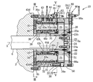
- the slide lock device 10 according to the present invention is attached to the extension shaft portion 6 a on the left end side of the crankshaft 6 and the main body frame 3.
- the slide lock device 10 includes a flange member 20, a main body member 30, an auxiliary main body member 50, a plurality of holding holes 31 and a plurality of pin members 32, a first locking means 60, a second locking means 80, and the like. ing.
- the extension shaft portion 6a protrudes outside the outer surface on the left end side of the main body frame 3 by a predetermined length.
- the flange member 20 is an annular member that is externally fitted to the extension shaft portion 6a and is fixed so as not to be relatively rotatable.
- the flange member 20 is integrally formed at a cylindrical portion 21 that is tightly fitted on the tip half of the extension shaft portion 6a and is fixed so as not to be relatively rotatable, and an axially outer end portion of the cylindrical portion 21;
- the shaft member 6 has an annular flange portion 22 parallel to a plane orthogonal to the axis X of the shaft member 6.
- the thickness of the flange portion 22 in the axial direction is set to a predetermined thickness.
- the flange member 20 is rotationally restricted so as not to rotate relative to the extension shaft portion 6a by a plurality of wedge bodies 23 firmly inserted between the plurality of wedge-shaped grooves 23a formed in the cylindrical portion 21 and the extension shaft portion 6a. And are coupled so as not to move relative to the axis X direction.
- the plurality of wedge bodies 23 are fixed by bolts 23b to a holding plate 24 fixed by bolts 24a to the ends of the extension shaft portions 6a.
- a key may be interposed between the extension shaft portion 6a and the tube portion 21.
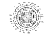
- FIG. 8 for example, six arc-shaped introduction holes 25 are formed in the flange portion 22 in a penetrating manner.
- a predetermined portion on the distal end side of the pin member 32 can be introduced into the introduction hole 25, the circumferential width of the introduction hole 25 is about 2.5 times the diameter of the pin member 32, and the angle ⁇ in FIG. It is.
- At least one pair of pin members 32 facing each other with the axis X of the shaft is introduced into the pair of introduction holes 25, and then the shaft member 6 is rotated by a small angle so that the remaining pair of pin members 32 is paired with a pair. It is introduced into the introduction hole 25.
- the four pin members 32 are respectively introduced into the four introduction holes 25.
- the main body member 30 includes a half of the base end side (the main body frame 3 side) of the extension shaft portion 6 a, an annular member 33 that is externally fitted to the cylindrical portion 21 and fixed to the main body frame 3, and a distal end of the annular member 33.
- the ring member 34 is fixed.
- the annular member 33 is disposed closer to the main body frame 3 than the flange portion 21 and faces the flange portion 21 with a gap of several mm.
- the annular member 33 has an annular fixing flange 35 that comes into contact with the outer surface of the main body frame 3, and the main body member 30 is fixed to the main body frame 3 by fixing the fixing flange 35 to the main body frame 3 with a plurality of bolts 35a. It is fixed to the outer surface of the frame 3.
- the ring member 34 is fixed to the distal end surface (outer end surface) of the outer peripheral side portion of the annular member 33 with a plurality of bolts 34 a and surrounds the outer peripheral side of the flange
- the holding hole 31 has a circular cross section, and a pin member 32 is mounted in the holding hole 31 so as to be movable in a direction parallel to the axis X.
- the holding hole 31 is formed inside a cylindrical cylinder member 36 fixed to the mounting hole of the annular member 33.
- a sleeve-like air passage forming member 38 is mounted in a cylindrical hole 37 formed in the main body member 30 on the inner peripheral side of the four cylinder members 36.
- the base end side of the holding hole 31 and the cylinder member 36 is sealed with a circular lid member 39, and this lid member 39 is fixed to the annular member 33 with four bolts 39a.
- the pin member 32 includes a rod portion of a piston member that is slidably mounted in the holding hole 31.
- An actuator 40 is provided for driving the pin member 32 in a retracted position shown by a solid line in FIG. 2 and an advanced position shown by a solid line in FIG. 4, and this actuator 40 is composed of a double-acting air cylinder. Yes.
- the auxiliary main body member 50 is an annular member that faces the flange portion 22 from the side opposite to the four holding holes 31 and is fixed to the main body member 30 with a plurality of bolts (not shown).
- the auxiliary main body member 50 is formed with four support holes 51 having a circular cross section corresponding to the four holding holes 31.
- the number of holding holes 31 and the number of support holes 51 are not limited to four, and may be three or less, or five or more.
- the pin member 32 When the pin member 32 is in the retracted position, the pin member 32 is held in the holding hole 31 and is retracted to the proximal end side from the introduction hole 25. When the pin member 32 is in the advanced position, a predetermined portion (about half) of the tip end side of the pin member 32 advances from the holding hole 31 and penetrates one of the introduction holes 25, and the tip end portion enters the corresponding support hole 51. It will be in the inserted state.
- the actuator 40 has a forward air chamber 41 and a backward air chamber 42.
- one first air supply / discharge port 43 common to the four forward air chambers 41 and one second air supply / discharge port 44 common to the four backward air chambers 42 are annular.
- the member 33 is provided.
- the first and second air supply / discharge ports 43 and 44 are respectively connected to a pressurized air supply source by an air passage (hose or pipe).
- the first air supply / discharge port 43 includes an annular air passage 43a formed in the cylinder member 36, an air passage 43b formed in the main body member 30, an annular air passage 43c formed in the air passage forming member 38, and this annular air.
- the four forward air chambers 41 are communicated with each other via an air passage 43d for communicating the passage 43c with the forward air chamber 41.
- the second air supply / discharge port 44 includes a sleeve-like air passage 44 a on the outer peripheral side of the cylinder member 36, an air passage 44 b formed in the cylinder member 36, an air passage 44 c formed in the main body member 30, and an air passage formation member 38.
- the four return air chambers 42 are communicated with each other via an annular air passage 44d formed in the above.
- pressurized air is supplied to the first air supply / discharge port 43 to supply pressurized air to the four forward air chambers 41, and the second air supply / discharge port 44 is supplied from the four backward air chambers 42.
- the pressurized air is supplied to the second air supply / discharge port 44, pressurized air is supplied to the four backward air chambers 42, and first air is supplied from the four forward air chambers 41.
- the pressurized air is discharged to the discharge port 43, the four pin members 32 move from the advanced position to the retracted position.
- the first axis X At least one pair of pin members 32 facing each other across the front end passes through the introduction hole 25 and the front end portion is inserted into the corresponding pair of support holes 51. At this time, the tips of the remaining pair of pin members 32 are in contact with the inner surface of the flange portion 22.
- the tip end side of the pair of pin members 32 that are in contact with the flange portion 22 is predetermined. Each part penetrates through the introduction hole 25, and the tip side part is inserted into the corresponding pair of support holes 51.
- the pair of pin members 32 [a] restricts the flange portion 22 (that is, the flange member 20 and the shaft member 6) from rotating in the clockwise direction in FIG. 8, and the remaining pair of pins
- the flange portion 22 (that is, the flange member 20 and the shaft member 6) is restricted by the member 32 [b] from rotating in the counterclockwise direction in FIG.
- the shaft member 6 can be regulated so as not to rotate, and the slide 2 can be locked so as not to move up and down.
- the first locking means 60 locks the four pin members 32 in the retracted position during the operation of the press machine 1.
- a locking engagement portion 32 a formed of an annular groove is formed in the vicinity of the outer periphery of the vicinity of the tip of the pin member 32.
- the first locking means 60 and the first locking member 61 are rotationally driven around the axis X over the locked position and the unlocked position.
- First driving means 62 is included.
- the first lock member 61 (corresponding to the first annular plate member) is a plate member parallel to a plane orthogonal to the axis X, and is disposed on the flange portion side end surface of the annular member 33 or in the vicinity thereof. It is rotatably mounted in an annular groove formed between 33 and the ring member 34.
- the first lock member 61 includes four through holes 61b through which the four pin members 32 can respectively penetrate, and four plate portions formed on one end side (clockwise end in FIG. 5) of the through holes 61b.
- 1 lock part 61a and the arm part 63 extended outside from the circular-arc-shaped opening part 33a formed in the outer peripheral side wall part of the annular member 33 are provided.
- the circumferential width of the through hole 61 b is somewhat larger than the diameter of the pin member 32, and the radial width of the through hole 61 b is set slightly larger than the diameter of the pin member 32.
- One end of the through hole 61b is formed in a straight portion that is substantially orthogonal to the circumferential direction centered on the axis X, and a first portion that engages with the locking engagement portion 32a of the pin member 32 with a plate portion including the straight portion.
- One lock portion 61a is formed.
- the other end of the through hole 61b has a semicircular arc shape.
- the first drive means 62 includes a first air cylinder 64 that can rotate the arm portion 63 of the first lock member 61 counterclockwise in FIG. 5 to drive the first lock member 61 to the lock position, A tension spring 65 that elastically biases the lock member 61 to the unlock position shown in FIG. 6 is provided.
- the first air cylinder 64 is a single acting and spring return type cylinder, and is fixed to a bracket 64a fixed to the annular member 33 in the vicinity of the opening 33a, and an engagement fitting 64b at the tip of the rod is an arm.
- the portion 63 is engaged.
- the first air cylinder 64 is connected to an air supply hose (not shown) extending from a pressurized air supply source.
- One end of the tension spring 65 is connected to a pin 65a fixed to the arm portion 63, and the other end is connected to a bracket 64a.
- the first detection means 70 for detecting whether the position of the first lock member 61 is the locked position or the unlocked position is provided (see FIGS. 2, 4 to 6).
- the first detection means 70 is, for example, a proximity switch attached to a bracket 70 a fixed to the outer peripheral surface of the annular member 33.
- the detection unit 70b is close to and opposed to the arm unit 63, and only when all the pin members 32 are in the retracted position and the first lock member 61 is in the locked position, the proximity switch is turned on and the first lock member is turned on.
- the proximity switch is turned off.
- a contact detection switch or an optical detection switch may be employed instead of the proximity switch.
- the second locking means 80 locks the four pin members 32 at the advanced position when the press machine 1 is stopped and held in a state where the elevation of the slide 2 is prohibited.
- the second lock means 80 is a ring-shaped second lock member 81 shown in FIGS. 8 and 9, and the second lock member 81 is driven to rotate about the axis X over the lock position and the unlock position.
- Second driving means 82 is included.
- the second lock member 81 (corresponding to the second annular plate member) is a plate member parallel to a plane orthogonal to the axis X, and the end surface of the auxiliary main body member 50 opposite to the flange member 20 or the vicinity thereof.
- the auxiliary body member 50 is disposed at a position and is rotatably mounted between the auxiliary body member 50 and a ring member 88a fixed to a cover plate 88 fixed to the outer end surface of the auxiliary body member 50.
- the second lock member 81 includes four first through holes 81b through which the four pin members 32 can pass, and four plate portions on one end side (clockwise end in FIG. 8) of the through holes 81b. 2 lock portions 81a and arm portions 83 extending outward from arcuate openings 50a formed in the outer peripheral side wall portion of the auxiliary main body member 50.
- the circumferential width of the through hole 81 b is somewhat larger than the diameter of the pin member 32, and the radial width of the through hole 81 b is set slightly larger than the diameter of the pin member 32.
- One end of the through hole 81b is formed in a straight line portion that is substantially orthogonal to the circumferential direction centered on the axis X, and is engaged with the locking engagement portion 32a of the pin member 32 by a plate portion including the straight line portion.
- a two-lock portion 81a is formed.
- the other end of the through hole 81b has a semicircular arc shape.
- the second drive means 82 includes a second air cylinder 84 that can rotate the arm portion 83 of the second lock member 81 counterclockwise in FIG. 8 to drive the second lock member 81 to the lock position, A tension spring 85 that elastically biases the lock member 81 to the unlock position shown in FIG. 9 is provided.
- the second air cylinder 84 is a single-acting and spring return type cylinder, and is fixed to a bracket 84a fixed to the auxiliary main body member 50 in the vicinity of the opening 50a, and an engagement fitting 84b at the tip of the rod is provided.
- the arm portion 83 is engaged.
- the second air cylinder 84 is connected to an air supply hose (not shown) extending from a pressurized air supply source.
- One end of the tension spring 85 is connected to a pin 85a fixed to the arm portion 83, and the other end is connected to a bracket 84a.
- Second detection means 90 is provided for detecting whether the position of the second lock member 81 is the locked position or the unlocked position.
- the second detection means 90 is, for example, a proximity switch attached to a bracket 90a fixed with the cover plate 88 sandwiched between the outer end surfaces of the auxiliary main body member 50.
- the detection unit 90b is close to and opposed to the arm 83, and the proximity switch is turned on when the second lock member 81 is in the locked position, and the proximity switch is turned off when the second lock member 81 is in the unlocked position.
- a contact detection switch or an optical detection switch may be employed.
- the slide lock device 1 During operation of the press machine 1, the four pin members 32 are held in the retracted position, and the first lock member 61 is held in the locked position. For this reason, even if a malfunction of the control system or malfunction of the actuator 40 occurs, the four pin members 32 hold the retracted position. Since the first lock member 61 is held in the locked position by the urging force of the tension spring 65, the first lock member 61 holds the locked position even when pressurized air cannot be supplied to the first air cylinder 64. In other words, the mechanism is excellent in fail-safe reliability.
- the four pin members 32 are held in the advanced position, and the second lock member 81 is held in the locked position. Therefore, the shaft member 6 cannot be rotated and is locked so that the slide 2 does not descend. Since the second lock member 81 is held at the lock position, the four pin members 32 hold the advanced position even if an operator's erroneous operation, a control system failure, an actuator 40 failure or malfunction occurs. Since the second lock member 81 is held in the locked position by the urging force of the tension spring 85, the second lock member 81 holds the locked position even when pressurized air cannot be supplied to the second air cylinder 84. In other words, the mechanism is excellent in fail-safe reliability.
- the lock engagement portions 32a are formed on the four pin members 32, and the four first lock portions 61a that are simultaneously engaged with the four lock engagement portions 32a are formed on the first lock member 61, so that the first drive is performed. Since the four pin members 32 are locked by driving the first lock member 61 to the lock position by the means 62, the configuration of the first lock means 60 is simplified. The same applies to the second locking means 80. Since the first and second lock means 60 and 80 are mainly composed of the first and second lock members 61 and 81 which are annular plate members parallel to a plane orthogonal to the axis, the first and second lock means 60 and 80 have a compact configuration and are slidably locked. The apparatus 10 can be downsized.
- the four first lock portions 61a of the first lock member 61 are engaged with and disengaged from the locking engagement portions 32a of the four pin members 32 from the circumferential direction, which is a direction orthogonal to the axis X, respectively.
- a lock function can be obtained.
- the pin member 32 is supported at both ends by the holding hole 31 and the support hole 51 on both sides of the introduction hole 25 in a state where the four pin members 32 are switched to the advanced position. Therefore, it is advantageous in terms of strength of the pin member 32, and is advantageous in securing durability of the holding hole 31 and the pin member 32.
- the first detection means 70 for detecting whether the position of the first lock member 61 is the locked position or the unlocked position it can be detected that all the pin members 32 are locked in the retracted position. It can also be detected that at least one or all of the pin members 32 are not in the retracted position. Since the second detection means 90 for detecting whether the position of the second lock member 81 is the lock position or the unlock position is provided, the unlock position is detected by the first detection means 70 and the lock position is detected by the second detection means 90. In this case, it can be confirmed that all the pin members 32 are located at the advanced position and are in the locked state. However, the condition is that pressurized air is supplied to the first air supply / discharge port 43.
- the actuator 40 for driving the pin member 32 is composed of a double-acting air cylinder incorporated in the annular member 33, the configuration of the actuator 30 can be simplified. In addition, since pressurized air is supplied / discharged from the first and second air supply / discharge ports 43 and 44 common to the four actuators 40, the configuration of the actuator 40 can be simplified.
- the number of holding holes 31, support holes 51, and pin members 32 is not limited to four, and may be three or less, or five or more.
- the number of introduction holes 25 is not limited to 6, and may be 5 or less, or 7 or more. Depending on the number of introduction holes 25, the size of the introduction holes 25 in the circumferential direction can be set as appropriate.
- the actuator 40 can be composed of a fluid pressure cylinder such as an air cylinder or a hydraulic cylinder.
- the first and second air cylinders 64 and 84 can be configured by fluid pressure cylinders such as air cylinders and hydraulic cylinders, or solenoid actuators.
- the first and second driving means 62 and 82 can be constituted by double-acting fluid pressure cylinders, and the tension springs 65 and 85 can be omitted.
- the four proximity switches 95 corresponding to the four pin members 32 are provided on the lid member 88, and the four pin members are detected by detecting that the four proximity switches 95 are turned on. You may comprise so that it can detect reliably that 32 is located in an advance position.
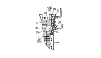
- the slide lock device 10A includes only the first and second drive means 62 and 82 of the first and second lock means 60 and 80 and the first and second detection means 70 and 90 in the slide lock apparatus 10. Since it is a changed device, only the changed configuration will be described, and the same main components will be denoted by the same reference numerals and description thereof will be omitted.
- the first driving means 62 ⁇ / b> A of the first locking means 60 ⁇ / b> A is provided in a pair of hollow portions 100 formed in a portion between the holding holes 31 of the saddle annular member 33.
- the first air cylinder 101 is a spring return type air cylinder, the axial center of which is parallel to the axial center X, and a conical member 104 having a conical portion 104a at the tip is attached to the tip of the piston rod 101a.
- a conical portion 104 a faces the circular hole 103.
- the pair of tension springs 102 urges the first lock member 61A toward the lock position shown in FIG. 12 (counterclockwise direction in FIG. 12).
- the conical portion 104a has a circular hole 103. Have retreated from.
- pressurized air is supplied to the first air cylinder 101 to extend the piston rod 101a, and the conical portion 104a is inserted into the circular hole 103 so that the first locking
- the member 61A is slightly rotated in the clockwise direction in FIG.
- the first detection means 70A has a proximity switch disposed in a cavity formed in the annular member 33, and when the first lock member 61A is in the locked position, the detection unit 105 is detached from the detection hole 106 and the first lock member.
- the proximity switch is turned on because it faces the 61A plate.
- the proximity switch is turned OFF because the detection unit 105 of the proximity switch faces the detection hole 106 formed in the first lock member 61A.
- the second driving means 82A of the second locking means 80A locks the pair of second air cylinders 110 fixed to the outer surface of the lid member 88 and the second locking member 81A. It has a pair of tension springs 111 that are driven back to the rear, and a pair of circular holes 112 formed in the second lock member 81A.
- the second air cylinder 110 is a spring return type air cylinder, and its axial center is arranged in parallel with the second lock member 81A and in the circumferential direction.
- the arm member 113 is fixed to the tip of the piston rod 110a of the second air cylinder 110. The arm member 113 passes through an opening hole 114 formed in the lid member 88 and extends toward the second lock member 81A perpendicularly to the second lock member 81A and engages with the circular hole 112.
- the pair of tension springs 111 urge the second lock member 81A toward the lock position shown in FIG. 13 (counterclockwise direction in FIG. 13). At this lock position, as shown in FIG. The arm member 113 is in contact with the edge of the circular hole 112 (the edge in the clockwise direction in FIG. 13).
- pressurized air is supplied to the second air cylinder 110 to extend the piston rod 110a, and the second lock member 81A is unlocked via the arm member 113. Slightly turn (clockwise in FIG. 13).
- the second detection means 90A is configured by a proximity switch fixed to the lid member 88.
- the detection unit 115 is detached from the detection hole 116 and is placed on the plate portion of the second lock member 81A. Since they face each other, the proximity switch is turned on.
- the proximity switch is turned OFF because the detection unit 115 of the proximity switch faces the detection hole 116 of the second lock member 81A.
- a cover member 99 that covers the outside of the second air cylinder 110 and the second detection means 90A is fixed to the lid member 88.
- the first and second drive means 62A and 82A and the first and second detection means 70A and 90A can be disposed radially inside the outer peripheral contours of the first and second lock members 61A and 81A. Since the member 30 and the auxiliary main body member 50 do not protrude to the outer peripheral side, the slide lock device can be downsized. Other operations and effects are substantially the same as those of the first embodiment, and thus description thereof is omitted.
- the present invention provides a slide lock device that can securely lock a slide of a press machine as required.
Landscapes
- Engineering & Computer Science (AREA)
- Mechanical Engineering (AREA)
- Control Of Presses (AREA)
- Mounting, Exchange, And Manufacturing Of Dies (AREA)
Abstract
Description
このスライドロック装置においては、ヘリカルギヤの歯幅方向に並べて3組のロックユニットを設け、ロックユニットの下端側にヘリカルギヤのギヤ歯間の谷部に係合可能な係合爪を設け、その係合爪をロックユニット内に設けた油圧式アクチュエータで進退駆動する。スライドをロックする際、3組のロックユニットを同時に駆動して3つの係合爪を進出側へ駆動し、何れか1つの係合爪をギヤ歯間の谷部に係合させ、鋼球を含むボールロック機構により係合爪をロックすることにより、ヘリカルギヤをロック状態にしてスライドをロックする。
この安全ロック機構においては、プレスの軸部材を貫通させた静止部材が本体フレームに固定され、この静止部材に形成した複数の保持孔に複数のロックピンが移動可能に装着されている。この静止部材に軸方向の外側から対向する被ロック部材が軸部材に固定され、この被ロック部材の外周近傍部には複数のロックピンの内周側半分を受容する複数の円弧状のリセスが形成され、これらリセスの周方向端部にはロックピンを受け止め可能な複数のロック用歯部が形成されている。
しかも、複数のロックピンを後退位置にロックするロック機構や進出位置にロックするロック機構を備えていない。そのため、オペレータの誤操作又は制御系の故障等により環状流体圧シリンダが誤動作すると、安全ロック機構が誤動作し、軸部材及びスライドをロック状態から誤ってアンロック状態に切換えたり、その反対に、アンロック状態から誤ってロック状態に切換えたりする虞がある。
(1)前記複数の保持孔と反対側からフランジ部に対向し且つ本体部材に固定された補助本体部材と、前記複数のピン部材の先端側部分を挿入可能に前記補助本体部材に形成された複数の支持孔とを設け、前記ピン部材が進出位置に移動したとき、前記導入孔を貫通したピン部材の先端側部分が対応する前記支持孔に貫通状に挿入されるように構成する。
(3)前記(2)において、前記第2ロック部材が前記補助本体部材のうちの前記フランジ部材と反対側の端面の近傍位置に配置される。
(4)前記第1ロック部材の位置がロック位置かアンロック位置かを検知する第1検知手段と、前記第2ロック部材の位置がロック位置かアンロック位置かを検知する第2検知手段とを設ける。
(6)前記(5)において、前記流体圧シリンダは前記ピストン部材を進出させる為の往動流体室と前記ピストン部材を後退させる為の復動流体室とを有し、複数の流体圧シリンダの複数の往動流体室は流体圧供給/排出用の共通の1つの第1ポートに接続され、複数の流体圧シリンダの複数の復動流体室は流体圧供給/排出用の共通の1つの第2ポートに接続される。
(8)前記第2駆動手段が、前記第2ロック部材をアンロック位置へ駆動する少なくとも1つの流体圧シリンダと、前記第2ロック部材をロック位置へ付勢する少なくとも1つの引っ張りスプリングとを有する。
(11)前記軸部材の回転位相がどのような回転位相であっても、前記進出位置にした複数のピン部材の先端側所定部分を複数の導入孔に導入可能に構成した。
第1ロック部材の複数の第1ロック部が、複数のピン部材のロック用係合部に周方向から係脱するため、信頼性の高いロック機能を得ることができる。このことは、第2ロック部材についても同様である。
スライドロック装置10は、フランジ部材20と、本体部材30と、補助本体部材50と、複数の保持孔31及び複数のピン部材32と、第1ロック手段60と、第2ロック手段80等を備えている。
4つのアクチュエータ40における4つの往動エア室41に共通の1つの第1エア供給/排出ポート43と、4つの復動エア室42に共通の1つの第2エア供給/排出ポート44とが環状部材33に設けられている。第1,第2エア供給/排出ポート43,44は、加圧エア供給源にエア通路(ホース又は配管)により夫々接続されている。
上記とは逆に、第2エア供給/排出ポート44に加圧エアを供給して4つの復動エア室42に加圧エアを夫々供給し、4つの往動エア室41から第1エア供給/排出ポート43へ加圧エアを排出すると、4つのピン部材32が進出位置から後退位置へ移動する。
第1ロック手段60は、プレス機械1 の稼働中に、4つのピン部材32を後退位置にロックするものである。ピン部材32の先端近傍部の外周近傍部には環状溝からなるロック用係合部32aが形成されている。第1ロック手段60は、図5,図6に示す環状の第1ロック部材61と、この第1ロック部材61をロック位置とアンロック位置とに亙って軸心Xの回りに回転駆動する第1駆動手段62を有する。第1ロック部材61(第1環状板部材に相当する)は、軸心Xと直交する平面と平行な板部材であり、環状部材33のフランジ部側端面又はその近傍位置に配置され、環状部材33とリング部材34の間に形成された環状溝に回動可能に装着されている。
4つのピン部材32を後退位置に保持して、第1ロック部材61を図5に示すロック位置にした状態では、4つの第1ロック部61aが対応するロック用係合部32aに夫々係合してピン部材32が軸心X方向へ移動不能になり、後退位置に保持される。
第2ロック手段80は、図8、図9に示す環状の第2ロック部材81と、この第2ロック部材81をロック位置とアンロック位置とに亙って軸心Xの回りに回転駆動する第2駆動手段82を有する。第2ロック部材81(第2環状板部材に相当する)は、軸心Xと直交する平面と平行な板部材であり、補助本体部材50のうちのフランジ部材20と反対側の端面又はその近傍位置に配置され、補助本体部材50と、この補助本体部材50の外端面に固定された蓋板88に固着されたリング部材88aとの間に回動可能に装着されている。
4つのピン部材32を進出位置に保持して、第2ロック部材81を図8に示すロック位置にした状態では、4つの第2ロック部81aが対応するロック用係合部32aに夫々係合してピン部材32が軸心X方向へ移動不能になり、進出位置に保持される。
第2エアシリンダ84は、単動型かつスプリング復帰型のシリンダであり、前記開口部50aの近傍において補助本体部材50に固定されたブラケット84aに固定され、そのロッドの先端の係合金具84bが腕部83に係合している。この第2エアシリンダ84は加圧エア供給源から延びるエア供給ホース(図示略)に接続されている。引っ張りスプリング85の一端は腕部83に固定されたピン85aに連結され、他端はブラケット84aに連結されている。
プレス機械1の稼働中においては、4つのピン部材32を後退位置に保持し、第1ロック部材61をロック位置に保持する。そのため、制御系の誤動作やアクチュエータ40の誤動作が発生しても、4つのピン部材32が後退位置を保持する。引っ張りスプリング65の付勢力で第1ロック部材61をロック位置に保持するため、第1エアシリンダ64へ加圧エアを供給不能になっても第1ロック部材61はロック位置を保持する。つまり、フェールセーフの信頼性に優れた機構になっている。
第1,第2ロック手段60,80は、軸心と直交する平面と平行な環状板部材である第1,第2ロック部材61,81を主体として構成するため、コンパクトな構成となり、スライドロック装置10の小型化を図ることができる。
第2ロック部材81の位置がロック位置かアンロック位置かを検知する第2検知手段90を設けたため、第1検知手段70によりアンロック位置を検知し且つ第2検知手段90によりロック位置を検知した場合に、全部のピン部材32が進出位置に位置し且つロック状態であると確認することができる。但し、第1エア供給/排出ポート43に加圧エアが供給されていることを条件とする。
1)保持孔31と支持孔51とピン部材32の数は4つに限定されるものではなく、3つ以下でもよく5つ以上でもよい。導入孔25の数は6つに限定されるものではなく、5つ以下でもよく7つ以上でもよい。導入孔25の数に応じて導入孔25の周方向のサイズも適宜設定可能である。
3)第1,第2駆動手段62,82を複動型流体圧シリンダで構成し、引っ張りスプリング65,85を省略することもできる。
Claims (12)
- プレス機械の本体フレームに支持されたスライドの昇降動作と連動して回転する軸部材を回転不能にロックするプレス機械のスライドロック装置において、
前記軸部材に外嵌されて相対回転不能に固定され且つ前記軸部材の軸心と直交する平面と平行なフランジ部を有するフランジ部材と、
前記軸部材に外嵌させて前記本体フレームに固定され且つ前記フランジ部に本体フレーム側から対向する環状部材を有する環状の本体部材と、
前記環状部材に前記軸心と平行に形成された複数の保持孔に移動可能に夫々装着された複数のピン部材と、
前記複数のピン部材を、前記保持孔に保持した後退位置と先端側所定部分を前記保持孔から進出させた進出位置とに亙って夫々駆動する為の複数のアクチュエータと、
前記進出位置にした複数のピン部材の前記先端側所定部分を導入する為に、前記フランジ部に周方向に設定間隔おきに形成され且つ周方向幅がピン部材の直径よりも大きな断面円弧形の複数の導入孔と、
前記複数のピン部材の先端近傍部に夫々形成された複数のロック用係合部と、
前記後退位置にした複数のピン部材の複数のロック用係合部に周方向から夫々係脱可能な複数の第1ロック部を介して複数のピン部材を後退位置にロック可能な環状の第1ロック部材と、
複数のピン部材を後退位置にロックするロック位置とアンロック位置とに亙って前記第1ロック部材を前記軸心の回りに回動駆動可能な第1駆動手段と、
前記進出位置にした複数のピン部材の複数のロック用係合部に周方向から夫々係脱可能な複数の第2ロック部を介して複数のピン部材を進出位置にロック可能な環状の第2ロック部材と、
複数のピン部材を進出位置にロックするロック位置とアンロック位置とに亙って前記第2ロック部材を前記軸心の回りに回動駆動可能な第2駆動手段と、
を備えたことを特徴とするプレス機械のスライドロック装置。 - 前記複数の保持孔と反対側からフランジ部に対向し且つ本体部材に固定された補助本体部材と、前記複数のピン部材の先端側部分を挿入可能に前記補助本体部材に形成された複数の支持孔とを設け、
前記ピン部材が進出位置に移動したとき、前記導入孔を貫通したピン部材の先端側部分が対応する前記支持孔に貫通状に挿入されるように構成したことを特徴とする請求項1に記載のプレス機械のスライドロック装置。 - 前記第1ロック部材が、前記環状部材の前記フランジ部側端面の近傍位置に配置されたことを特徴とする請求項1に記載のプレス機械のスライドロック装置。
- 前記第2ロック部材が前記補助本体部材のうちの前記フランジ部材と反対側の端面の近傍位置に配置されたことを特徴とする請求項2に記載のプレス機械のスライドロック装置。
- 前記第1ロック部材の位置がロック位置かアンロック位置かを検知する第1検知手段と、前記第2ロック部材の位置がロック位置かアンロック位置かを検知する第2検知手段とを設けたことを特徴とする請求項1に記載のプレス機械のスライドロック装置。
- 前記アクチュエータが複動型の流体圧シリンダで構成され、この流体圧シリンダのピストンロッド部材のロッド部でもって前記ピン部材を構成したことを特徴とする請求項1に記載のプレス機械のスライドロック装置。
- 前記流体圧シリンダは前記ピストン部材を進出させる為の往動流体室と前記ピストン部材を後退させる為の復動流体室とを有し、
複数の流体圧シリンダの複数の往動流体室は流体圧供給/排出用の共通の1つの第1ポートに接続され、複数の流体圧シリンダの複数の復動流体室は流体圧供給/排出用の共通の1つの第2ポートに接続されたことを特徴とする請求項6に記載のプレス機械のスライドロック装置。 - 前記第1駆動手段が、前記第1ロック部材をアンロック位置へ駆動する少なくとも1つの流体圧シリンダと、前記第1ロック部材をロック位置へ付勢する少なくとも1つの引っ張りスプリングとを有することを特徴とする請求項1に記載のプレス機械のスライドロック装置。
- 前記第2駆動手段が、前記第2ロック部材をアンロック位置へ駆動する少なくとも1つの流体圧シリンダと、前記第2ロック部材をロック位置へ付勢する少なくとも1つの引っ張りスプリングとを有することを特徴とする請求項1に記載のプレス機械のスライドロック装置。
- 前記第1ロック部材は、前記軸心と直交する平面と平行な第1環状板部材と、この第1環状板部材に前記複数のピン部材に対応するように夫々形成され且つ前記ピン部材の直径よりも大きな周方向幅を有する複数の貫通穴と、これら複数の貫通穴の周方向一端側の板部分でもって形成された複数の第1ロック部とを有することを特徴とする請求項1に記載のプレス機械のスライドロック装置。
- 前記第2ロック部材は、前記軸心と直交する平面と平行な第2環状板部材と、この第2環状板部材に前記複数のピン部材に対応するように夫々形成され且つ前記ピン部材の直径よりも大きな周方向幅を有する複数の貫通穴と、これら複数の貫通穴の周方向一端側の板部分でもって形成された複数の第2ロック部とを有することを特徴とする請求項1に記載のプレス機械のスライドロック装置。
- 前記軸部材の回転位相がどのような回転位相であっても、前記進出位置にした複数のピン部材の先端側所定部分を複数の導入孔に導入可能に構成したことを特徴とする請求項1に記載のプレス機械のスライドロック装置。
Priority Applications (7)
| Application Number | Priority Date | Filing Date | Title |
|---|---|---|---|
| EP13874728.2A EP2955010B1 (en) | 2013-02-08 | 2013-02-08 | Slide lock apparatus for press machine |
| US14/760,530 US9789659B2 (en) | 2013-02-08 | 2013-02-08 | Slide lock apparatus for press machine |
| ES13874728T ES2759783T3 (es) | 2013-02-08 | 2013-02-08 | Aparato de bloqueo de carro para prensa |
| KR1020157023649A KR101947730B1 (ko) | 2013-02-08 | 2013-02-08 | 프레스 기계의 슬라이드 로크 장치 |
| CN201380072114.0A CN104968488B (zh) | 2013-02-08 | 2013-02-08 | 冲压机的滑块锁定装置 |
| JP2014560612A JP6076380B2 (ja) | 2013-02-08 | 2013-02-08 | プレス機械のスライドロック装置 |
| PCT/JP2013/053068 WO2014122775A1 (ja) | 2013-02-08 | 2013-02-08 | プレス機械のスライドロック装置 |
Applications Claiming Priority (1)
| Application Number | Priority Date | Filing Date | Title |
|---|---|---|---|
| PCT/JP2013/053068 WO2014122775A1 (ja) | 2013-02-08 | 2013-02-08 | プレス機械のスライドロック装置 |
Publications (1)
| Publication Number | Publication Date |
|---|---|
| WO2014122775A1 true WO2014122775A1 (ja) | 2014-08-14 |
Family
ID=51299387
Family Applications (1)
| Application Number | Title | Priority Date | Filing Date |
|---|---|---|---|
| PCT/JP2013/053068 WO2014122775A1 (ja) | 2013-02-08 | 2013-02-08 | プレス機械のスライドロック装置 |
Country Status (7)
| Country | Link |
|---|---|
| US (1) | US9789659B2 (ja) |
| EP (1) | EP2955010B1 (ja) |
| JP (1) | JP6076380B2 (ja) |
| KR (1) | KR101947730B1 (ja) |
| CN (1) | CN104968488B (ja) |
| ES (1) | ES2759783T3 (ja) |
| WO (1) | WO2014122775A1 (ja) |
Cited By (1)
| Publication number | Priority date | Publication date | Assignee | Title |
|---|---|---|---|---|
| KR20170091105A (ko) | 2014-12-02 | 2017-08-08 | 파스칼 엔지니어링 가부시키가이샤 | 프레스 기계의 슬라이드 로크 장치 |
Families Citing this family (1)
| Publication number | Priority date | Publication date | Assignee | Title |
|---|---|---|---|---|
| USD806148S1 (en) * | 2015-03-09 | 2017-12-26 | Webo Werkzeugbau Oberschwaben Gmbh | Counter holder for a precision press machine |
Citations (5)
| Publication number | Priority date | Publication date | Assignee | Title |
|---|---|---|---|---|
| US2185551A (en) | 1938-10-27 | 1940-01-02 | Glasner | Safety locking mechanism for presses and the like |
| JPS51123972A (en) * | 1975-04-23 | 1976-10-29 | Aida Eng Ltd | Method for preventing double-dropping in a press machine |
| US5357780A (en) * | 1992-04-13 | 1994-10-25 | Schuler Incorporated | Press slide locking apparatus |
| US5845751A (en) * | 1996-07-01 | 1998-12-08 | Chant; William | Safety locking device |
| JP2007245172A (ja) | 2006-03-14 | 2007-09-27 | Komatsu Ltd | スライドのロック装置およびこれを備えたプレス機械 |
Family Cites Families (14)
| Publication number | Priority date | Publication date | Assignee | Title |
|---|---|---|---|---|
| US3603210A (en) * | 1967-09-25 | 1971-09-07 | Peter Florjancic | Hydraulic apparatus, preferably closing apparatus for injection molding machines |
| US4737093A (en) * | 1985-06-07 | 1988-04-12 | Kabushiki Kaisha Sanjoseiki Seisakusho | Die locking mechanism for a molding apparatus |
| DE4330870C1 (de) * | 1993-09-11 | 1994-09-08 | Keiper Recaro Gmbh Co | Verriegelungssystem für verstellbare Fahrzeugsitze |
| DE4400232C2 (de) * | 1994-01-05 | 2002-09-12 | Hammerstein Gmbh C Rob | Stufenfreie Feststellvorrichtung für einen einstellbaren Fahrzeugsitz |
| JP3769864B2 (ja) * | 1997-03-27 | 2006-04-26 | 株式会社豊田自動織機 | 産業車輌のブレーキ装置 |
| US5845781A (en) | 1997-05-29 | 1998-12-08 | Alico; Robert J. | Container that converts into a copyholder |
| KR20010024974A (ko) * | 1999-02-22 | 2001-03-26 | 파스칼 가부시키가이샤 | 기계 프레스의 클러치ㆍ브레이크 장치 |
| JP4365469B2 (ja) * | 1999-02-24 | 2009-11-18 | パスカルエンジニアリング株式会社 | 油圧式ロック装置 |
| JP2001129698A (ja) * | 1999-10-29 | 2001-05-15 | Aida Eng Ltd | スライドロック装置 |
| JP4206860B2 (ja) * | 2003-08-13 | 2009-01-14 | 株式会社Ihi | ロック装置及びプレス装置 |
| JP4937801B2 (ja) * | 2007-03-19 | 2012-05-23 | パスカルエンジニアリング株式会社 | アクチュエータ、アクチュエータを備えたアンクランプ装置および加工装置 |
| JP2010264783A (ja) * | 2009-05-12 | 2010-11-25 | Gkn Driveline Japan Ltd | 駆動モータ用動力伝達装置 |
| BR112014032039B1 (pt) * | 2012-07-24 | 2022-03-15 | Pascal Engineering Corporation | Dispositivo de bloqueio do deslizador para prensa mecânica |
| KR102235518B1 (ko) * | 2014-12-02 | 2021-04-01 | 파스칼 엔지니어링 가부시키가이샤 | 프레스 기계의 슬라이드 로크 장치 |
-
2013
- 2013-02-08 ES ES13874728T patent/ES2759783T3/es active Active
- 2013-02-08 US US14/760,530 patent/US9789659B2/en active Active
- 2013-02-08 EP EP13874728.2A patent/EP2955010B1/en active Active
- 2013-02-08 JP JP2014560612A patent/JP6076380B2/ja active Active
- 2013-02-08 CN CN201380072114.0A patent/CN104968488B/zh active Active
- 2013-02-08 WO PCT/JP2013/053068 patent/WO2014122775A1/ja active Application Filing
- 2013-02-08 KR KR1020157023649A patent/KR101947730B1/ko active IP Right Grant
Patent Citations (5)
| Publication number | Priority date | Publication date | Assignee | Title |
|---|---|---|---|---|
| US2185551A (en) | 1938-10-27 | 1940-01-02 | Glasner | Safety locking mechanism for presses and the like |
| JPS51123972A (en) * | 1975-04-23 | 1976-10-29 | Aida Eng Ltd | Method for preventing double-dropping in a press machine |
| US5357780A (en) * | 1992-04-13 | 1994-10-25 | Schuler Incorporated | Press slide locking apparatus |
| US5845751A (en) * | 1996-07-01 | 1998-12-08 | Chant; William | Safety locking device |
| JP2007245172A (ja) | 2006-03-14 | 2007-09-27 | Komatsu Ltd | スライドのロック装置およびこれを備えたプレス機械 |
Cited By (4)
| Publication number | Priority date | Publication date | Assignee | Title |
|---|---|---|---|---|
| KR20170091105A (ko) | 2014-12-02 | 2017-08-08 | 파스칼 엔지니어링 가부시키가이샤 | 프레스 기계의 슬라이드 로크 장치 |
| EP3228445A4 (en) * | 2014-12-02 | 2018-08-22 | Pascal Engineering Corporation | Slide lock device for press machine |
| US10486386B2 (en) | 2014-12-02 | 2019-11-26 | Pascal Engineering Corporation | Slide lock device for press machine |
| KR102235518B1 (ko) | 2014-12-02 | 2021-04-01 | 파스칼 엔지니어링 가부시키가이샤 | 프레스 기계의 슬라이드 로크 장치 |
Also Published As
| Publication number | Publication date |
|---|---|
| EP2955010A4 (en) | 2017-02-08 |
| US20150336347A1 (en) | 2015-11-26 |
| KR20150116877A (ko) | 2015-10-16 |
| CN104968488A (zh) | 2015-10-07 |
| JPWO2014122775A1 (ja) | 2017-01-26 |
| US9789659B2 (en) | 2017-10-17 |
| EP2955010A1 (en) | 2015-12-16 |
| KR101947730B1 (ko) | 2019-02-13 |
| EP2955010B1 (en) | 2019-11-13 |
| ES2759783T3 (es) | 2020-05-12 |
| JP6076380B2 (ja) | 2017-02-08 |
| CN104968488B (zh) | 2016-10-12 |
Similar Documents
| Publication | Publication Date | Title |
|---|---|---|
| KR101056636B1 (ko) | 클램프 장치 | |
| US9387539B2 (en) | Gripper with emergency release | |
| JP2000326167A (ja) | クランプ装置 | |
| JP2012166276A (ja) | クランプ装置のロッド位置検出装置 | |
| ITMO20100250A1 (it) | "dispositivo per il bloccaggio di cerchi di ruote per veicoli su macchine da autofficina, particolarmente macchine smontagomme o simili" | |
| JP6076380B2 (ja) | プレス機械のスライドロック装置 | |
| JP4877787B2 (ja) | 位置決め装置およびその装置を備えた位置決めシステム | |
| US6832539B2 (en) | Cylinder lock | |
| JP7318375B2 (ja) | 工作物把持装置 | |
| US20140117631A1 (en) | Clamping device | |
| JP5944002B2 (ja) | プレス機械のスライドロック装置 | |
| JP6441381B2 (ja) | プレス機械のスライドロック装置 | |
| US6309150B1 (en) | Chuck actuator | |
| US4332186A (en) | Hydraulic actuator for lathe chuck | |
| WO2008050430A1 (fr) | Dispositif de bridage | |
| US10641299B2 (en) | Monitoring device for tool turret | |
| JP6590217B2 (ja) | シリンダ装置 | |
| JP2008110416A (ja) | 流体圧駆動割出装置 | |
| KR101203755B1 (ko) | 그리퍼 아암의 중량공구 이탈 방지장치 | |
| JP5439159B2 (ja) | 工作機械の主軸装置 | |
| JPS5874906A (ja) | 回転する圧力媒体シリンダ | |
| US20110168013A1 (en) | Piston assembly | |
| WO2019081164A1 (en) | ARRANGEMENT, SYSTEM AND METHOD OF PROTECTION |
Legal Events
| Date | Code | Title | Description |
|---|---|---|---|
| 121 | Ep: the epo has been informed by wipo that ep was designated in this application |
Ref document number: 13874728 Country of ref document: EP Kind code of ref document: A1 |
|
| WWE | Wipo information: entry into national phase |
Ref document number: 14760530 Country of ref document: US |
|
| ENP | Entry into the national phase |
Ref document number: 2014560612 Country of ref document: JP Kind code of ref document: A |
|
| NENP | Non-entry into the national phase |
Ref country code: DE |
|
| WWE | Wipo information: entry into national phase |
Ref document number: 2013874728 Country of ref document: EP |
|
| ENP | Entry into the national phase |
Ref document number: 20157023649 Country of ref document: KR Kind code of ref document: A |