WO2014119690A1 - 水蒸気透過性測定ユニットおよび水蒸気透過性測定方法 - Google Patents
水蒸気透過性測定ユニットおよび水蒸気透過性測定方法 Download PDFInfo
- Publication number
- WO2014119690A1 WO2014119690A1 PCT/JP2014/052167 JP2014052167W WO2014119690A1 WO 2014119690 A1 WO2014119690 A1 WO 2014119690A1 JP 2014052167 W JP2014052167 W JP 2014052167W WO 2014119690 A1 WO2014119690 A1 WO 2014119690A1
- Authority
- WO
- WIPO (PCT)
- Prior art keywords
- water vapor
- vapor permeability
- unit
- permeability
- sample
- Prior art date
- Legal status (The legal status is an assumption and is not a legal conclusion. Google has not performed a legal analysis and makes no representation as to the accuracy of the status listed.)
- Ceased
Links
Images



Classifications
-
- G—PHYSICS
- G01—MEASURING; TESTING
- G01N—INVESTIGATING OR ANALYSING MATERIALS BY DETERMINING THEIR CHEMICAL OR PHYSICAL PROPERTIES
- G01N15/00—Investigating characteristics of particles; Investigating permeability, pore-volume or surface-area of porous materials
- G01N15/08—Investigating permeability, pore-volume, or surface area of porous materials
- G01N15/0806—Details, e.g. sample holders, mounting samples for testing
-
- G—PHYSICS
- G01—MEASURING; TESTING
- G01N—INVESTIGATING OR ANALYSING MATERIALS BY DETERMINING THEIR CHEMICAL OR PHYSICAL PROPERTIES
- G01N15/00—Investigating characteristics of particles; Investigating permeability, pore-volume or surface-area of porous materials
- G01N15/08—Investigating permeability, pore-volume, or surface area of porous materials
- G01N15/082—Investigating permeability by forcing a fluid through a sample
- G01N15/0826—Investigating permeability by forcing a fluid through a sample and measuring fluid flow rate, i.e. permeation rate or pressure change
Definitions
- the present invention relates to a water vapor permeability measuring unit and a water vapor permeability measuring method for simply measuring the water vapor permeability of a barrier film.
- a barrier film having a low water vapor permeability such as water vapor or oxygen using a polymer as a raw material has been widely used for packaging materials for foods, pharmaceuticals, and electronic parts.
- utilization in the field of organic electronics is also being studied due to its high transparency, lightness, flexibility, and moldability.
- materials with a water vapor permeability (WVTR) of up to about 10 ⁇ 2 g / m 2 day have been used.
- WVTR water vapor permeability
- WVTR water vapor permeability
- the calcium corrosion method is an example of this (see Patent Documents 1, 2, or 3).
- a thin film of metallic calcium is formed on one side of the sample and sealed, and the area of the corroded portion of metallic calcium caused by water vapor that has permeated the sample is measured by image processing to measure the amount of water vapor permeated. Is the method.
- There is also a method of detecting a corroded portion of calcium metal with an atomic force microscope see Patent Document 4).
- WVTR water vapor permeability
- the method of measuring water vapor permeability using metal corrosion caused by water vapor In the method of measuring water vapor permeability using metal corrosion caused by water vapor, advanced technology and special equipment are required. In other words, the work of forming a metal thin film corroded by water vapor on the sample and sealing it must be performed in an environment where water vapor is blocked, and because the quality of the work greatly affects the measurement accuracy, advanced technology is required. It is. Furthermore, a special apparatus such as a thin film forming apparatus or a glove box is necessary for the work. From these facts, the method of measuring the water vapor permeability by utilizing the corrosion of the metal by water vapor has a problem that it can be evaluated only in a place having a high technology and a special apparatus.
- the present invention provides a water vapor permeability measurement unit and a measurement method for more easily measuring the water vapor permeability of a sample using metal corrosion by water vapor.
- the present invention provides a water vapor permeability measurement unit comprising a water vapor detection unit for detecting water vapor and a water vapor transmission suppression unit for suppressing water vapor transmission, and the entire outer surface of the water vapor detection unit is covered with the water vapor transmission suppression unit. To do.
- the apparatus includes a water vapor detection unit that detects water vapor, a water vapor transmission suppression unit that suppresses transmission of water vapor, and a water vapor transmission prevention unit that blocks water vapor transmission, and a part of the outer surface of the water vapor detection unit is formed by the water vapor transmission suppression unit.
- a water vapor permeability measurement unit in which the entire outer surface of the water vapor detection part is covered with a water vapor permeation prevention part.
- it is a method for measuring water vapor permeability using the water vapor permeability measuring unit of the present invention, and provides a method for measuring water vapor permeability in which a sample is arranged on the water vapor detector via the water vapor permeation suppressor. .
- the water vapor permeability measuring unit which performs the measurement of the water vapor permeability of the sample using the corrosion of the metal by water vapor more simply can be provided.
- An expensive apparatus such as a thin film forming apparatus or a glove box is not required.
- No time is required for forming the water vapor detector.
- the water vapor permeability measuring unit of the present invention will be described below.
- the first embodiment of the water vapor permeability measurement unit includes a water vapor detection unit that detects water vapor and a water vapor transmission suppression unit that suppresses the transmission of water vapor, and the entire outer surface of the water vapor detection unit is covered with the water vapor transmission suppression unit. It will be. An example of a specific configuration will be described later with reference to FIG.
- the second embodiment of the water vapor permeability measurement unit includes a water vapor detection unit that detects water vapor, a water vapor transmission suppression unit that suppresses transmission of water vapor, and a water vapor transmission prevention unit that blocks water vapor transmission.
- the third embodiment of the water vapor permeability measuring unit is formed by adhering an electrode to the water vapor detector in the first and second embodiments. An example of a specific configuration will be described later with reference to FIG.
- the water vapor permeability measuring unit can be made by a person who has advanced technology and special equipment.
- the water vapor permeability measuring unit can be stored and moved for a long time in a dry state enclosed in a can or the like and shielded from the outside air.
- the measurer takes out the water vapor permeability measurement unit at an arbitrary measurement location, attaches the sample to the water vapor permeability measurement unit using a sample sealing material with extremely low water vapor permeability, and
- the moisture permeability can be measured by standing in a constant temperature and humidity chamber where the humidity is controlled and quantifying the amount of water vapor that has permeated through the sample for a certain period of time.
- the water vapor permeability measurement unit By using the water vapor permeability measurement unit, it is possible to perform a water vapor permeability measurement operation outside the glove box. From the above, the water vapor permeability of the barrier film having a water vapor permeability (WVTR) of 1 ⁇ 10 ⁇ 2 g / m 2 ⁇ day or less is required for the measurer without the need for advanced technology and special equipment. It is possible to stably perform the measurement by a simple operation.
- WVTR water vapor permeability
- the water vapor permeability measuring unit preferably has a structure in which the entire outer surface of the water vapor detection unit is covered with the water vapor transmission suppression unit. At the time of measuring the water vapor permeability, it is necessary to have a structure in which water vapor does not enter between the water vapor permeation suppression portion and the sample disposed thereon, and it is desirable to use a sample sealing material with extremely low water vapor permeability.
- the sample and the water vapor permeation suppressor may or may not be in close contact with each other, but in the case of close contact, the position of water vapor transmission can be specified in addition to the water vapor permeability of the sample.
- the water vapor permeability measurement unit may have a structure in which a part of the outer surface of the water vapor detection unit is covered with a water vapor transmission suppression unit and the entire outer surface of the water vapor detection unit is covered with a water vapor transmission prevention unit.
- a water vapor permeation blocking unit a metal or glass that does not corrode by water vapor can be used as a member that completely blocks water vapor.
- the sample and the water vapor permeation suppressor may or may not be in close contact with each other, but in the case of close contact, the position of water vapor transmission can be specified in addition to the water vapor permeability of the sample.
- the water vapor permeation suppression unit of the water vapor permeability measurement unit is installed with the electrode adhered to the water vapor detection unit, and the entire outer surface of the water vapor detection unit is the water vapor permeation suppression unit alone, or the water vapor permeation suppression unit and the water vapor permeation prevention unit It is better to have a structure covered with As the water vapor permeation blocking unit, a metal or glass that does not corrode by water vapor can be used as a member that completely blocks water vapor.
- the sample and the water vapor permeation suppressor may or may not be in close contact with each other, but in the case of close contact, the position of water vapor transmission can be specified in addition to the water vapor permeability of the sample.
- the sample sealing material is a material having an extremely low water vapor permeability used for making a structure in which water vapor does not enter between the water vapor permeation suppression portion and the sample when measuring the water vapor permeability.
- ethylene vinyl acetate copolymer, polyvinyl butyral, butyl rubber, silicone resin, epoxy resin, etc. can be used, preferably butyl rubber, silicone resin, epoxy resin, etc. can be used, more preferably epoxy resin.
- the water vapor permeation preventing unit can use a metal, glass, or the like that does not corrode by water vapor as a member that completely blocks water vapor.
- nickel, aluminum, titanium, platinum, copper, silver, gold, or the like can be used, preferably aluminum, copper, gold, or the like can be used, and aluminum is more preferably used. it can.
- the water vapor detector in the present invention is a metal having a property of corroding by water vapor. It is desirable that the water vapor detector is used after being formed into a foil shape or a granular shape depending on the type of measurement and the shape of the sample.
- steam detection part it is good to contain either calcium, magnesium, or its alloy. 1 mol of calcium, magnesium, or an alloy thereof reacts with 2 mol of water vapor according to the following formula 1 to form a hydroxide and corrode.
- M in Formula 1 represents calcium, magnesium, or an alloy thereof.
- a method for detecting water vapor by the water vapor detector a method of analyzing the corrosion amount of the water vapor detector using the corroded volume can be used.
- the foil-shaped water vapor detector can be used to determine the amount of corrosion of the water vapor detector.
- the area of the corroded metal in the water vapor detector is S (cm 2 ), the thickness of the water vapor detector is L (cm), the molecular weight of the metal in the water vapor detector is M 1 , and the molecular weight after corrosion of the metal in the water vapor detector is M 2 , where the metal density of the detection unit is d 1 (g / cm 3 ), and the density after corrosion of the metal of the detection unit is d 2 (g / cm 3 ), the water vapor detected by the water vapor detection unit
- the mass W (g) is obtained by the following formula 2.
- ⁇ is a thickness correction coefficient after corrosion of the metal in the water vapor detection portion, and is obtained by the following equation 3. 1 ⁇ ⁇ (M 2 / d 2 ) / (M 1 / d 1 ) (Formula 3)
- an arbitrary device such as a laser microscope, an optical microscope, a digital camera, a scanner or the like may be used, and image analysis of the obtained image is performed. It is also possible to quantify the corrosion area and the shape and position of the corrosion area.
- a method for detecting water vapor by the water vapor detection unit a method of analyzing the corrosion amount of the water vapor detection unit using a change in electric resistance can be used.
- a water vapor permeability measurement unit in which an electrode is previously installed in the water vapor detection unit is used, a change in electrical resistance of the water vapor detection unit can be measured in the measurement.
- the electrical resistance of the water vapor detector increases.
- the water vapor permeation suppressor is preferably made of a polymer material because it is excellent in processability and smoothness and is easy to design optimal water vapor permeability.
- a material and thickness having an appropriate water vapor permeability can be selected from polycarbonate, polyethylene, polypropylene, polyethylene terephthalate, polyvinyl chloride, polyvinylidene chloride, acrylonitrile, polyamide, polyimide, and the like.
- the water vapor permeation suppressor can be an organic-inorganic composite material that further suppresses water vapor permeability.
- the surface of the polymer material coated with silica or diamond-like carbon, or a composite material composed of the polymer material and clay mineral can be used.
- the water vapor permeation suppression unit is dense and smooth. By being dense and smooth, the surface shape can be measured without causing a defect in the barrier film of sample 7. “Dense” means that there are no pores having a pore diameter exceeding 1 nm penetrating from the surface in contact with the sample of the water vapor permeation suppression portion to the other surface. This is sufficient if the surface of the water vapor permeation suppressor is observed with a surface observation means such as a scanning electron microscope or an atomic force microscope, and no pore having a pore diameter of 1 nm is found.
- a height difference of 1 ⁇ m at a distance of 100 ⁇ m more preferably no step or unevenness exceeding a height difference of 0.1 ⁇ m at a distance of 100 ⁇ m.
- the water vapor permeability measurement unit should be optimized according to the shape of the sample. For example, when measuring a flat film-shaped sample without bending, the water vapor permeation suppression unit is plate-shaped in the water vapor permeability measurement unit. For example, when measuring a container such as a bottle, it is possible to measure by introducing a plurality of them into the container as they are, for example, in a columnar shape or a spherical shape as an optimum structure for handling.
- the method for determining the water vapor permeability WVTR (g / m 2 ⁇ day) in the measurement of water vapor permeability using the water vapor permeability measurement unit is as follows.
- the water vapor passes through the sample and the water vapor permeation suppression unit, reaches the water vapor detection unit, and is detected by the above method.
- the total water vapor permeability P tot (g / m 2 ⁇ day ⁇ Pa) is the mass W (g) of water vapor detected in the water vapor detector, from the time when the sample is mounted on the water vapor permeability measurement unit until the end of measurement.
- the water vapor permeability P s (g / m 2 ⁇ day ⁇ Pa) of the water vapor permeation suppressor is assumed to be known at the time of manufacture.
- the permeation flux can be expressed by the following formulas 5 and 6.
- J f P f (p f ⁇ p b ) (Formula 5)
- J s P s (p b ⁇ p p ) (Formula 6)
- J f Js (Formula 7)
- J ((P f ⁇ P s ) / (P f + P s )) ⁇ (p f ⁇ p p ) (Formula 8)
- the total water vapor transmission rate P tot can be expressed by Equation 9 below.
- P tot (P f ⁇ P s ) / (P f + P s ) (Formula 9) From this, it is possible to obtain P f of the sample from the total water vapor transmission rate P tot and the water vapor transmission rate P s of the water vapor transmission suppression unit. Furthermore, it deform
- P tot P f / (P f / P s +1) (Formula 10) From this, next P tot ⁇ P f when P s is sufficiently larger than P f, better overall water vapor permeability as a water vapor permeability of the sample.
- the water vapor permeation flux J s 0 (g / m 2 ⁇ day) reaching the water vapor detection section before the measurement is started after mounting the sample on the water vapor permeability measurement unit has a differential pressure of p f ⁇ p Since it is p (Pa), it can be expressed by the following equation (13).
- J s 0 P s ⁇ (p f ⁇ p p ) (Formula 13)
- the total water vapor amount W (g) reaching the water vapor detection unit is determined by the water vapor transmission suppression unit during the time t 0 (day) until the sample is mounted on the water vapor permeability measurement unit.
- the water vapor permeability of the sample is determined from the viewpoint of suppressing the water vapor permeation until the measurement is started after the sample is mounted on the water vapor permeability measurement unit and performing the measurement stably with a simple operation. It is desirable that the water vapor permeability of the permeation suppressor is 1/3000 to 1 / fold, more preferably 1/1000 to 1 / fold, and even more preferably 1/100 to 1 / fold.
- An object of the present invention is to stably measure the water vapor permeability of a barrier film having a water vapor permeable WVTR of 1 ⁇ 10 ⁇ 2 g / m 2 ⁇ day or less by a simple operation.
- the water vapor permeability of the water vapor permeation suppressor is desirably 30 g / m 2 ⁇ day or less, more preferably 10 g / m 2 ⁇ day or less, and even more preferably 1 g / m 2 ⁇ day.
- the ratio of the water vapor permeability of the water vapor permeation suppressor to the water vapor permeability of the sample is preferably 1 or more, more preferably 10 or more, even more preferably. Is preferably 100 or more.
- the water vapor permeability measuring unit is preliminarily mass-produced in a special production facility, and further sealed with a dry gas in a container such as a can that can be kept completely sealed over a period of several years. For this reason, since the water vapor permeability measuring unit is not exposed to the atmosphere until immediately before the measurement work, it can be transported and sold while maintaining the quality, and can be stably stored for a long time. .
- the water vapor permeability measuring unit has a structure in which a water vapor permeability suppressing unit having a small water vapor permeability is cut off from the outside. Can be prevented from reacting with.
- a measurement method using the water vapor permeability measurement unit 10 will be described with reference to FIG.
- the sample 7 is installed in the water vapor permeability measurement unit 10, and the periphery of the sample 7 is sealed and attached with the sample sealing material 8. This is left still in the constant temperature and humidity chamber 9, and it measures with the measuring apparatus 11 after a fixed time.
- this sample sealing material 8 ethylene vinyl acetate copolymer, polyvinyl butyral, butyl rubber, silicone resin, epoxy resin and the like can be used, preferably butyl rubber, silicone resin, epoxy resin and the like can be used.
- an epoxy resin can be used.
- the water vapor permeability is about 0.14 g / m 2 ⁇ day when the thickness of the sample sealing material 8 is 5 mm. Since the area of the sample sealing material 8 is sufficiently smaller than that of the sample 7, the amount of water vapor that passes through the sample sealing material 8 can be sufficiently ignored.
- the water vapor detection unit 2 is covered with the water vapor transmission suppression unit 1 made of the aforementioned polymer material or organic-inorganic composite material, and further from the metal film. It has the structure sealed with the water-vapor-permeation prevention part 4 and the water-vapor-permeation prevention part 3 which consists of resin.
- the water vapor detection unit 2 preferably includes calcium, magnesium, or an alloy thereof.
- the thickness is 0.01 ⁇ m or more, preferably 0.05 ⁇ m or more, more preferably 0.1 ⁇ m or more from the viewpoint of measuring water vapor permeability with high sensitivity. From the viewpoint of measuring water vapor permeability with a high permeation amount, the thickness is 100 ⁇ m or less, preferably 10 ⁇ m or less, more preferably 1 ⁇ m or less.
- the metal film of the water vapor permeation preventing unit 4 is required to have a water vapor permeability lower than at least the water vapor permeability of the sample (see FIG. 1), and this can be achieved by using a metal film having a property of not transmitting water vapor.
- nickel, aluminum, titanium, platinum, copper, silver, gold or the like can be used for the metal film, preferably aluminum, copper, gold or the like can be used, more preferably aluminum. be able to.
- the thickness is 0.01 ⁇ m or more, preferably 0.05 ⁇ m or more, more preferably 0.1 ⁇ m or more, and the thickness is 100 ⁇ m from the viewpoint of simple and low cost production.
- the water vapor permeation blocking unit 4 made of a metal film blocks a small amount of water vapor that cannot be suppressed by the water vapor permeation blocking unit 3 made of resin. This makes it possible to measure water vapor permeability with higher accuracy.
- the water vapor permeation blocking unit 3 made of the above resin can use ethylene vinyl acetate copolymer, polyvinyl butyral, butyl rubber, silicone resin, epoxy resin, etc., preferably butyl rubber, silicone resin, epoxy resin, etc. More preferably, an epoxy resin can be used.
- an epoxy resin is used as the water vapor permeation prevention unit 3 made of resin, the water vapor permeation rate is about 0.14 g / m 2 ⁇ day when the water vapor permeation prevention unit 3 made of resin is set to a thickness of 5 mm.
- the water vapor detection unit 2 is entirely or partially covered with the water vapor transmission suppression unit 1, and further the water vapor transmission suppression unit of the water vapor detection unit 2. All the surfaces not covered with 1 are sealed with a water vapor permeation preventing part 3 made of resin and a glass plate 5 as a water vapor permeation prevention part.
- a glass plate 5 soda glass, borosilicate glass, quartz glass, tempered glass, or the like can be used, preferably borosilicate glass, tempered glass, or the like can be used, more preferably borosilicate glass can be used. .
- the glass plate 5 can block the water vapor transmission from the lower surface of the water vapor permeability measuring unit to the inside.
- the whole or part of the water vapor detecting unit 2 is covered with the water vapor permeation suppressing unit 1, and the electrode 6 for measuring electrical resistance is detected with water vapor.
- the surface of the water vapor detection unit 2 that is not covered with the water vapor permeation suppression unit 1 is sealed with a resin water vapor permeation prevention unit 3 and a glass plate 5.
- the electrical resistance of the water vapor detection unit 2 is measured by providing the electrode 6 so as to penetrate the water vapor permeation prevention unit 3 made of resin. By measuring the electrical resistance of the water vapor detector 2, the amount of corrosion of the water vapor detector 2 due to water vapor transmission can be derived, and the water vapor permeability can be measured.
- the water vapor detection unit 2 having a spherical shape or the like is entirely covered with the water vapor transmission suppression unit 1 (see FIG. 5A).
- the electrode 6 is attached to the water vapor detection unit 2.
- the water vapor permeation suppression unit 1 see FIG. 5C.
- the electrical resistance of the water vapor detection unit 2 due to water vapor transmission is measured.
- the amount of corrosion of the water vapor detector 2 due to water vapor permeation can be determined, and the water vapor permeability can be measured.
- the measurement apparatus 11 (11 a) of the first embodiment attaches the sample 7 to the water vapor permeation suppression unit 1 of the water vapor permeability measurement unit 10 and seals it with the sample sealing material 8. Then, it is left in the constant temperature and humidity chamber 9. An image of gloss or corrosion on the surface of the water vapor detector 2 is detected by the reflected light or image of the light emitted from the light emitting device 61 by the reflected light or image analyzer 62, and the water vapor permeability of the sample 7 is measured. .
- the incident light used here can be light having an arbitrary intensity and wavelength of infrared light, ultraviolet light, or visible light obtained from a halogen lamp, mercury lamp, UV lamp or the like, but preferably has a wavelength of 400 nm or more. Visible light having a wavelength of 800 nm or less, more preferably 500 nm to 700 nm can be used. Any angle can be used as the incident light angle and the reflected light detection angle. However, from the viewpoint of detection sensitivity, the angle is preferably perpendicular to the sample-side surface of the water vapor transmission suppressing unit of the water vapor transmission measuring unit 10. It is desirable to be. Here, the measurement of the reflected light and the image may be performed continuously or at an appropriate interval.
- a method of detecting using the reflected light or image analyzer 62 is performed by using a camera or video camera on the surface of the water vapor detection unit 2 of the water vapor permeability measurement unit 10.
- the reflected light or the image analysis device 62 having the above, etc. are taken, the image obtained by means such as image analysis using a computer is analyzed, the area of the water vapor detecting portion discolored by the water vapor is measured, and the water vapor transmission It is a method of measuring quantity.
- the measurement apparatus 11 (11 b) of the second embodiment attaches the sample 7 to the water vapor permeation suppression unit 1 of the water vapor permeability measurement unit 10 and surrounds the sample 7 with the sample sealing material 8. Seal and place in the constant temperature and humidity chamber 9.
- the opening portion due to corrosion of the water vapor detection unit 2 is detected by the transmitted light or image by the light emitted from the light emitting device 71 by image analysis by the transmitted light or image analysis device 72, and the water vapor permeability of the sample 7 is measured.
- the incident light used here can be light having an arbitrary intensity and wavelength of infrared light, ultraviolet light, or visible light obtained from a halogen lamp, mercury lamp, UV lamp or the like, but preferably has a wavelength of 400 nm or more. Visible light having a wavelength of 800 nm or less, more preferably 500 nm to 700 nm can be used. Any angle can be used as the incident light angle and the transmitted light detection angle. However, from the viewpoint of detection sensitivity, the angle is preferably perpendicular to the sample side surface of the water vapor transmission suppressing unit of the water vapor transmission measuring unit 10. It is desirable to be. Here, the measurement of the transmitted light and the image may be performed continuously or at an appropriate interval.
- the method of detecting using the transmitted light or image analyzer 72 is performed by using a camera or video camera for the surface of the water vapor detection unit 2 of the water vapor permeability measurement unit 10.
- the transmitted light or image analysis device 72 having the above or the like is taken, the image obtained by means such as image analysis using a computer is analyzed, the area of the water vapor detection portion discolored by water vapor is measured, and the water vapor transmission It is a method of measuring quantity.
- the water vapor transmission amount W (g) is calculated from (Equation 2) using the area S (cm 2 ) discolored by water vapor.
- Arbitrary temperature and humidity can be used as measurement conditions for water vapor permeability, but the measurement temperature is preferably 25 ° C. or more and 50 ° C. or less, more preferably 30 ° C. as a temperature range that is typically used for measurement. It is good to set it as 40 to 40 degreeC.
- the measurement humidity is preferably 50% (RH) or more and 90% (RH) or less, more preferably 80% (RH) or more and 90% (RH) or less as a standard humidity region used for measurement. Good.
- the measurement apparatus 11 (11 c) of the third embodiment attaches a measurement sample to the water vapor permeation suppression unit 1 of the water vapor permeability measurement unit 10, and surrounds the sample 7 with the sample sealing material 8. Seal and place in the constant temperature and humidity chamber 9.
- a gloss or corrosion image of the surface opposite to the sample 7 of the water vapor detector 2 due to the light emitted from the light emitting device 81 is detected by the reflected light or image analyzer 82 and the water vapor permeability of the sample 7 is measured. To do.
- the method of detecting using the reflected light or image analyzer 82 is performed by using a camera on the surface sealed by the glass plate 5 of the water vapor permeability measurement unit 10.
- the reflected light or image analysis device 82 having a video camera or the like is used to analyze the image obtained by means such as image analysis using a computer, and the area of the water vapor detection unit corroded by water vapor is measured.
- This is a method for measuring the amount of water vapor permeated.
- an image analysis method an arbitrary method such as a method of performing analysis at regular intervals or a method of performing analysis by tracking changes continuously can be used.
- the method of detecting using the reflected light or image analyzer 82 is a method of detecting the surface of the water vapor detection unit 2 of the water vapor permeability measurement unit with a camera or video camera.
- the water vapor transmission amount W (g) is calculated from (Equation 2) using the area S (cm 2 ) discolored by water vapor.
- the features of the configuration for detecting the reflected light on the upper surface side shown in FIG. 6, the configuration for detecting the transmitted light shown in FIG. 7, and the configuration for detecting the reflected light on the lower surface side shown in FIG. is there.
- the corrosion of the water vapor detection unit 2 is measured by a method of transmitting and reflecting measurement light through the sample or by image analysis, so that measurement can be performed when a transparent sample is used.
- the measurement apparatus 11b shown in FIG. 7 has an advantage that a general-purpose spectroscopic apparatus can be used instead of the image analysis apparatus because the corrosion of the water vapor detection unit 2 is measured by a method of transmitting measurement light through the sample or image analysis.
- the measurement apparatus 11c shown in FIG. 8 since the measurement light is incident from the opposite side of the sample and the corrosion of the water vapor detection unit 2 is measured by the reflected light or image analysis, even when the sample is not transparent Applicable.
- the measurement device 11 (11 d) of the fourth embodiment places the sample 7 on the water vapor permeation suppression unit 1 of the water vapor permeability measurement unit 10, and the sample sealing material 8 The periphery is sealed and left in the constant temperature and humidity chamber 9.
- the electrical resistance of the water vapor detection unit 2 is measured by the electric resistance measurement device 91 using the electrode 6 for measuring electrical resistance connected to the water vapor detection unit 2, and the water vapor permeability of the sample 7 is measured.
- a method of converting the electrical resistance of the water vapor detection unit 2 into water vapor permeability there is the following method. That is, the correlation between the mass of the water vapor detection unit corroded by the reaction with water and the value of electrical resistance is measured in advance. Based on this correlation, the corroded mass W Ca (g) of the water vapor detector is obtained from the value of the electrical resistance obtained during the water vapor transmission measurement.
- the measurement device 11d performs a method of measuring water vapor permeability using the water vapor permeability measurement unit 10, and the water vapor detection unit 2 is corroded by the water vapor transmitted through the sample 7 and the water vapor transmission suppression unit 1.
- the change in the electric resistance of the water vapor detection unit 2 is measured using the electrode 6 for measuring electric resistance.
- the electrical resistance value between the electrodes 6 for measuring electrical resistance is measured with an impedance analyzer (for example, Agilent 4294A) or a resistance measuring instrument (for example, E4982A manufactured by Agilent). Is obtained by measuring.
- the method of measuring the water vapor permeability by measuring the electric resistance using the water vapor permeability measuring unit 10 has an advantage that quantitative analysis is easy since the electric resistance value is obtained as a numerical value and the water vapor permeability is measured.
- the measurement apparatus 11 (11e) of the fifth embodiment includes a water vapor permeability measurement unit 10 in a container-like sample 7, a lid on the sample 7, and a constant temperature and humidity chamber. 9 to stand inside. Corrosion of a water vapor detector (not shown) is detected from light reflection or transmission or electrical resistance using an electrode, and the water vapor transmission rate is measured. For the measurement, the reflected light or image analysis devices 62 and 82, the transmitted light or image analysis device 72, and the electrical resistance measurement device 91 described above are used.
- a measurement result with high sensitivity can be obtained by a simple operation as compared with the case where the measurement is performed by the conventional measurement method. That is, in the conventional method, when installing the sample in the measuring apparatus, it is necessary to perform heating for removing the vacuum apparatus or the water vapor so that the water vapor is not taken into the apparatus, and the measurement operation is extremely complicated. It was. On the other hand, in this method, by using the water vapor permeation suppressor, it is possible to measure the water vapor permeability with high sensitivity without performing complicated operations required in the conventional metal calcium method.
- the highly sensitive measurement of water vapor permeability means that the water vapor permeability can be measured at a value of 1 ⁇ 10 ⁇ 2 g / m 2 ⁇ day or less.
- a water vapor permeability measurement test of a reference sample having no water vapor permeability is performed to confirm that the water vapor permeability is smaller than 1 ⁇ 10 ⁇ 4 g / m 2 ⁇ day. Accordingly, it can be determined that a value of 1 ⁇ 10 ⁇ 2 g / m 2 ⁇ day or less can be measured with high sensitivity when the water vapor permeability of the sample is measured.
- nickel, aluminum, titanium, platinum, copper, silver, gold or the like can be used, preferably aluminum, copper, gold or the like can be used, more preferably aluminum.
- the thickness of the reference sample that does not have water vapor permeability is 0.05 ⁇ m or more, preferably 0.1 ⁇ m or more, more preferably 0.5 ⁇ m or more.
- the water vapor transmission characteristics of a sample such as a barrier film can be evaluated with high sensitivity, simplicity, and low cost, so that the development of a water vapor barrier film and inspection before product shipment are made more efficient.
- the water vapor barrier film developed and manufactured in this way is used in organic electronics elements such as solar cells and organic light emitting devices, leading to an improvement in the product life.
- the transparent packaging which can be stored for a long period of time instead of a bottle and a can and the contents can be visually recognized becomes possible by using for food packaging.
Landscapes
- Chemical & Material Sciences (AREA)
- Physics & Mathematics (AREA)
- Analytical Chemistry (AREA)
- Dispersion Chemistry (AREA)
- Health & Medical Sciences (AREA)
- Life Sciences & Earth Sciences (AREA)
- Biochemistry (AREA)
- General Health & Medical Sciences (AREA)
- General Physics & Mathematics (AREA)
- Immunology (AREA)
- Pathology (AREA)
- Fluid Mechanics (AREA)
- Testing Resistance To Weather, Investigating Materials By Mechanical Methods (AREA)
- Sampling And Sample Adjustment (AREA)
Abstract
水蒸気を検出する水蒸気検出部と水蒸気の透過を抑制する水蒸気透過抑制部を備え、水蒸気検出部の外表面の全面が水蒸気透過抑制部により覆われてなる、もしくは水蒸気透過抑制部と水蒸気の透過を抑制する水蒸気透過抑制部と水蒸気の透過を阻止する水蒸気透過阻止部とを備え、水蒸気検出部の外表面の一部を水蒸気透過抑制部により、水蒸気検出部の外表面の残り全部を水蒸気透過阻止部により覆われてなる、水蒸気透過性測定ユニットを提供する。
Description
本発明は、バリアフィルムの水蒸気透過性を簡便に測定する水蒸気透過性測定ユニットおよび水蒸気透過性測定方法に関する。
高分子を素材に用いた水蒸気や酸素等の水蒸気透過性の低いバリアフィルムは、従来から食品・医薬品・電子部品の包装材料に広く用いられている。近年では、透明性、軽量性、柔軟性、成型加工性の高さから、有機エレクトロニクス分野における利用も検討されている。従来の包装材としては、水蒸気透過性(WVTR)については10―2g/m2day程度までの材料が用いられてきたが、近年研究が行われている有機エレクトロニクス分野においては、これよりはるかに低い10-6g/m2day程度の水蒸気透過性(WVTR)が必要とされる。
近年、水蒸気によって腐食する金属を利用して試料であるバリアフィルムの水蒸気透過性を高感度に測定する手法が提案されている。カルシウム腐食法はこの一例である(特許文献1、2、または3参照。)。カルシウム腐食法においては、試料の片側に金属カルシウムの薄膜を形成して封止し、試料を透過した水蒸気によって生じた金属カルシウムの腐食部分の面積を画像処理によって測定し、水蒸気透過量を測定する方法である。金属カルシウムの腐食部分を原子間力顕微鏡で検出する方法もあり(特許文献4参照。)、10-6g/m2day程度の水蒸気透過性(WVTR)も測定可能であると報告されている。水蒸気によって腐食する金属を利用して水蒸気透過性を測定する手法は、高感度な測定が可能であり、さらに金属の腐食した場所に基づいて、試料において水蒸気が透過した場所を特定できるという利点もある。
水蒸気による金属の腐食を利用して水蒸気透過性を測定する手法においては、高度な技術と特殊な装置が要求される。すなわち、水蒸気によって腐食する金属の薄膜を試料上に形成し封止する作業は水蒸気を遮断した環境で行う必要があり、作業の良し悪しが測定精度に大きく影響することから、高度な技術が必要である。さらに、その作業においては薄膜形成装置やグローブボックスといった特殊な装置が必要である。これらのことから、水蒸気による金属の腐食を利用して水蒸気透過性を測定する手法は、高度な技術と特殊な装置を有しているところでしか評価できないという課題を抱えていた。
本発明は、水蒸気による金属の腐食を利用した試料の水蒸気透過性の測定をより簡便に行う水蒸気透過性測定ユニットおよび測定方法を提供するものである。
水蒸気による金属の腐食を利用して水蒸気透過性を測定する手法においては、水蒸気の検出部を試料上に形成する必要があると考えられていた。発明者らは上記課題の解決に向けて鋭意検討を重ねた結果、水蒸気の検出部を試料とは異なる材料を用いて外部と遮断した構造を持つ水蒸気透過性測定ユニットを用いることで、課題を解決できることを見出した。
本発明は、水蒸気を検出する水蒸気検出部と水蒸気の透過を抑制する水蒸気透過抑制部を備え、水蒸気検出部の外表面の全面が水蒸気透過抑制部により覆われてなる水蒸気透過性測定ユニットを提供する。
また、水蒸気を検出する水蒸気検出部と水蒸気の透過を抑制する水蒸気透過抑制部と水蒸気の透過を阻止する水蒸気透過阻止部とを備え、水蒸気検出部の外表面の一部を水蒸気透過抑制部により、水蒸気検出部の外表面の残り全部を水蒸気透過阻止部により覆われてなる水蒸気透過性測定ユニットを提供する。
さらに、本発明の水蒸気透過性測定ユニットを用いた水蒸気透過性の測定方法であって、前記水蒸気検出部上に前記水蒸気透過抑制部を介して試料を配置する水蒸気透過性の測定方法を提供する。
本発明は、水蒸気を検出する水蒸気検出部と水蒸気の透過を抑制する水蒸気透過抑制部を備え、水蒸気検出部の外表面の全面が水蒸気透過抑制部により覆われてなる水蒸気透過性測定ユニットを提供する。
また、水蒸気を検出する水蒸気検出部と水蒸気の透過を抑制する水蒸気透過抑制部と水蒸気の透過を阻止する水蒸気透過阻止部とを備え、水蒸気検出部の外表面の一部を水蒸気透過抑制部により、水蒸気検出部の外表面の残り全部を水蒸気透過阻止部により覆われてなる水蒸気透過性測定ユニットを提供する。
さらに、本発明の水蒸気透過性測定ユニットを用いた水蒸気透過性の測定方法であって、前記水蒸気検出部上に前記水蒸気透過抑制部を介して試料を配置する水蒸気透過性の測定方法を提供する。
本発明によれば、水蒸気による金属の腐食を利用した試料の水蒸気透過性の測定をより簡便に行う水蒸気透過性測定ユニットを提供することができる。それにより、水蒸気透過性測定ユニットを用いてより簡便に水蒸気透過性を評価する水蒸気透過性測定装置が提供可能になる。
すなわち、水蒸気透過性評価が必要な者にとって下記の効果がある。
(1)薄膜形成装置やグローブボックスのような高価な装置を必要としない。
(2)水蒸気検出部の形成・封止に関わる高度な技術を必要としない。
(3)水蒸気検出部の形成に関わる時間が不要となる。
(4)大量に生産することで高品質で性能の安定した水蒸気透過性測定ユニットを作製できるようになるので、安定した水蒸気透過性の評価が可能になる。
(5)水蒸気透過性測定ユニットが大量生産されることで、安価に提供されることが期待できる。
すなわち、水蒸気透過性評価が必要な者にとって下記の効果がある。
(1)薄膜形成装置やグローブボックスのような高価な装置を必要としない。
(2)水蒸気検出部の形成・封止に関わる高度な技術を必要としない。
(3)水蒸気検出部の形成に関わる時間が不要となる。
(4)大量に生産することで高品質で性能の安定した水蒸気透過性測定ユニットを作製できるようになるので、安定した水蒸気透過性の評価が可能になる。
(5)水蒸気透過性測定ユニットが大量生産されることで、安価に提供されることが期待できる。
本発明の上記及び他の特徴及び利点は、適宜添付の図面を参照して、下記の記載からより明らかになるであろう。
本発明の水蒸気透過性測定ユニットについて、以下に説明する。
水蒸気透過性測定ユニットの第1の実施形態は、水蒸気を検出する水蒸気検出部と水蒸気の透過を抑制する水蒸気透過抑制部を備え、水蒸気検出部の外表面の全面が水蒸気透過抑制部により覆われてなるものである。具体的構成の一例は図2を参照して後述する。
水蒸気透過性測定ユニットの第2の実施形態は、水蒸気を検出する水蒸気検出部と水蒸気の透過を抑制する水蒸気透過抑制部と水蒸気の透過を阻止する水蒸気透過阻止部とを備え、水蒸気検出部の外表面の一部を水蒸気透過抑制部により、水蒸気検出部の外表面の残り全部を水蒸気透過阻止部により覆われてなるものである。具体的構成の一例は図3を参照して後述する。
水蒸気透過性測定ユニットの第3の実施形態は、上記第1、第2の実施形態において、水蒸気検出部に電極を接着して設置してなるものである。具体的構成の一例は図4を参照して後述する。
水蒸気透過性測定ユニットの第1の実施形態は、水蒸気を検出する水蒸気検出部と水蒸気の透過を抑制する水蒸気透過抑制部を備え、水蒸気検出部の外表面の全面が水蒸気透過抑制部により覆われてなるものである。具体的構成の一例は図2を参照して後述する。
水蒸気透過性測定ユニットの第2の実施形態は、水蒸気を検出する水蒸気検出部と水蒸気の透過を抑制する水蒸気透過抑制部と水蒸気の透過を阻止する水蒸気透過阻止部とを備え、水蒸気検出部の外表面の一部を水蒸気透過抑制部により、水蒸気検出部の外表面の残り全部を水蒸気透過阻止部により覆われてなるものである。具体的構成の一例は図3を参照して後述する。
水蒸気透過性測定ユニットの第3の実施形態は、上記第1、第2の実施形態において、水蒸気検出部に電極を接着して設置してなるものである。具体的構成の一例は図4を参照して後述する。
上記水蒸気透過性測定ユニットは、高度な技術と特殊な装置を有する者に作製を任せることができる。水蒸気透過性測定ユニットは、缶等に封入して外気と遮断した乾燥状態で長期の保管および移動が可能である。水蒸気透過性の測定に際しては、測定者は任意の測定場所において水蒸気透過性測定ユニットを取り出し、水蒸気透過性測定ユニットに水蒸気透過性の極めて低い試料封止材を用いて試料を装着して、温度と湿度が管理された恒温恒湿槽の中に静置し、一定時間において試料を透過した水蒸気の量を定量することによって、水蒸気透過性の測定を行うことができる。水蒸気透過性測定ユニットを用いることにより、水蒸気透過性の測定操作をグローブボックスの外において行うことが可能となる。以上のことから、測定者においては、高度な技術と特殊な装置を必要とせずに、水蒸気透過性(WVTR)が1×10⁻²g/m2・day以下であるバリアフィルムの水蒸気透過性の測定を、簡便な操作で安定して行うことが可能となる。
水蒸気透過性測定ユニットは、水蒸気検出部の外表面の全面を水蒸気透過抑制部で覆った構造とするのがよい。水蒸気透過性の測定時には、水蒸気透過抑制部とその上に配置される試料との間から水蒸気が入り込まない構造にする必要があり、水蒸気透過性の極めて低い試料封止材を用いることが望ましい。試料と水蒸気透過抑制部とは密着していてもしていなくても良いが、密着している場合には試料の水蒸気透過性に加えて水蒸気透過の位置を特定することが可能となる。
水蒸気透過性測定ユニットは、水蒸気検出部の外表面の一部を水蒸気透過抑制部で、水蒸気検出部の外表面の残り全部を水蒸気透過阻止部で覆った構造とするのがよい。水蒸気透過阻止部としては、水蒸気を完全に阻止する部材として、水蒸気によって腐食しない金属やガラス等を用いることができる。水蒸気透過性の測定時には、水蒸気透過抑制部とその上に配置される試料との間から水蒸気が入り込まない構造にする必要があり、水蒸気透過性の極めて低い試料封止材を用いることが望ましい。試料と水蒸気透過抑制部とは密着していてもしていなくても良いが、密着している場合には試料の水蒸気透過性に加えて水蒸気透過の位置を特定することが可能となる。
水蒸気透過性測定ユニットの水蒸気透過抑制部は、電極を水蒸気検出部に接着して設置し、かつ水蒸気検出部の外表面の全面を水蒸気透過抑制部のみ、または水蒸気透過抑制部と水蒸気透過阻止部を用いて覆った構造とするのがよい。水蒸気透過阻止部としては、水蒸気を完全に阻止する部材として、水蒸気によって腐食しない金属やガラス等を用いることができる。水蒸気透過性の測定時には、水蒸気透過抑制部とその上に配置される試料との間から水蒸気が入り込まない構造にする必要があり、水蒸気透過性の極めて低い試料封止材を用いることが望ましい。試料と水蒸気透過抑制部とは密着していてもしていなくても良いが、密着している場合には試料の水蒸気透過性に加えて水蒸気透過の位置を特定することが可能となる。
試料封止材は、水蒸気透過性の測定時に水蒸気透過抑制部と試料との間から水蒸気が入り込まない構造にするために用いる水蒸気透過性の極めて低い材料である。その材質としては、エチレン酢酸ビニル共重合体、ポリビニルブチラール、ブチルゴム、シリコーン樹脂、エポキシ樹脂等を用いることができ、好ましくはブチルゴム、シリコーン樹脂、エポキシ樹脂等を用いることができ、より好ましくはエポキシ樹脂を用いることができる。
水蒸気透過阻止部は、水蒸気を完全に阻止する部材として、水蒸気によって腐食しない金属やガラス等を用いることができる。水蒸気によって腐食しない金属としては、ニッケル、アルミニウム、チタン、白金、銅、銀、金等を用いることができ、好ましくはアルミニウム、銅、金等を用いることができ、より好ましくはアルミニウムを用いることができる。
水蒸気透過阻止部は、水蒸気を完全に阻止する部材として、水蒸気によって腐食しない金属やガラス等を用いることができる。水蒸気によって腐食しない金属としては、ニッケル、アルミニウム、チタン、白金、銅、銀、金等を用いることができ、好ましくはアルミニウム、銅、金等を用いることができ、より好ましくはアルミニウムを用いることができる。
本発明における水蒸気検出部とは、水蒸気によって腐食する性質を持つ金属である。水蒸気検出部は、測定の形式と試料の形状によって箔状または粒状等に成形して用いることが望ましい。水蒸気検出部としては、カルシウム、マグネシウム、またはその合金のいずれかを含むものとするのがよい。カルシウム、マグネシウム、またはその合金は、1モルが水蒸気2モルと次の式1の通り反応して水酸化物となり、腐食する。式1中のMは、カルシウム、マグネシウム、またはその合金を表す。
M+2H2O→M(OH)2+H2 (式1)
M+2H2O→M(OH)2+H2 (式1)
水蒸気検出部による水蒸気の検出方法としては、水蒸気検出部の腐食量を腐食した体積を用いて解析する方法を用いることができる。特許文献2で述べられている手法を参考にすると、箔状の水蒸気検出部を用いることで、水蒸気検出部の腐食量を利用して求めることができる。水蒸気検出部において腐食した金属の面積をS(cm2)、水蒸気検出部の厚さをL(cm)、水蒸気検出部の金属の分子量をM1、水蒸気検出部の金属の腐食後の分子量をM2、検出部の金属の密度をd1(g/cm3)、検出部の金属の腐食後の密度をd2(g/cm3)、とすると、水蒸気検出部において検出された水蒸気の質量W(g)は、次の式2で求められる。
W=18×2×S×L×α/M2 (式2)
ここで、αは水蒸気検出部の金属の腐食後の厚み補正係数であり、次の式3で求められる。
1<α≦(M2/d2)/(M1/d1) (式3)
水蒸気検出部において腐食した金属の面積S(cm2)を求める方法としては、レーザー顕微鏡、光学顕微鏡、デジタルカメラ、スキャナ等の任意の装置を用いてよく、得られた画像の画像解析を行って腐食面積や腐食面積の形状や位置を定量化することもできる。
水蒸気検出部による水蒸気の検出方法としては、水蒸気検出部の腐食量を電気抵抗の変化を用いて解析する方法を用いることができる。水蒸気検出部にあらかじめ電極を設置した水蒸気透過性測定ユニットを用いると、測定において水蒸気検出部の電気抵抗の変化を測定できる。水蒸気検出部が水蒸気と反応することによって、水蒸気検出部の電気抵抗が増加する。あらかじめ、水蒸気検出部の水蒸気による腐食量と電気抵抗値との関係を求めておくことで、未知の試料についても電気抵抗に基づいて透過した水蒸気の質量W(g)を求めることができる。
W=18×2×S×L×α/M2 (式2)
ここで、αは水蒸気検出部の金属の腐食後の厚み補正係数であり、次の式3で求められる。
1<α≦(M2/d2)/(M1/d1) (式3)
水蒸気検出部において腐食した金属の面積S(cm2)を求める方法としては、レーザー顕微鏡、光学顕微鏡、デジタルカメラ、スキャナ等の任意の装置を用いてよく、得られた画像の画像解析を行って腐食面積や腐食面積の形状や位置を定量化することもできる。
水蒸気検出部による水蒸気の検出方法としては、水蒸気検出部の腐食量を電気抵抗の変化を用いて解析する方法を用いることができる。水蒸気検出部にあらかじめ電極を設置した水蒸気透過性測定ユニットを用いると、測定において水蒸気検出部の電気抵抗の変化を測定できる。水蒸気検出部が水蒸気と反応することによって、水蒸気検出部の電気抵抗が増加する。あらかじめ、水蒸気検出部の水蒸気による腐食量と電気抵抗値との関係を求めておくことで、未知の試料についても電気抵抗に基づいて透過した水蒸気の質量W(g)を求めることができる。
水蒸気透過抑制部は、加工性と平滑性に優れていること、および最適な水蒸気透過性の設計が容易であることから、高分子材料とするのがよい。例えばポリカーボネート、ポリエチレン、ポリプロピレン、ポリエチレンテレフタレート、ポリ塩化ビニル、ポリ塩化ビニリデン、アクリロニトリル、ポリアミド、ポリイミドなどから、適当な水蒸気透過性を持つ材料と厚さを選ぶことができる。
水蒸気透過抑制部は、水蒸気透過性をさらに低く抑えた有機無機複合材料とすることができる。例えば高分子素材表面にシリカやダイヤモンドライクカーボンなどを被覆したもの、高分子素材と粘土鉱物からなる複合材料などを用いることができる。
水蒸気透過性測定ユニットにおいて、水蒸気透過抑制部は、緻密で平滑である。緻密で平滑であることにより表面の形状が試料7であるバリアフィルムに欠陥を生じることなく、測定できる。「緻密」とは、水蒸気透過抑制部の試料に接する面から他面へ貫通する孔径1nmを超える細孔がないことを意味する。このことは走査型電子顕微鏡や原子間力顕微鏡など表面観察手段で水蒸気透過抑制部表面を観察し、孔径1nmの細孔が見出されなければ十分である。これら表面観察手段では貫通しない細孔(例えば、表面の窪み)と貫通する細孔を区別することができないが、表面に細孔がないことを確認できれば貫通する細孔もないことを確認したことになる。なお、高分子材料において高分子鎖の原子レベルの隙間を指して「細孔」と呼ぶ例も見受けられるが、本発明においては高分子鎖の間に形成される原子レベル(すなわちnm以下)の隙間は細孔と考えない。
また、もとより微細な凹凸や穏やかな凹凸(うねり)が試料に影響を与えることはない。本発明における「平滑」とは100μmの距離で高低差10μmを超える段差や凹凸がないことを指す。好ましくは100μmの距離で高低差1μmを超える段差や凹凸がないこと、より好ましくは100μmの距離で高低差0.1μmを超える段差や凹凸がないことを指す。それは測定するバリアフィルムの厚さが一般的に数十μmであるためで、高低差は少なくともそれより小さい必要があるからである。高低差がバリアフィルムの厚みの1/100であれば試料に欠陥を生じることはない。
また、もとより微細な凹凸や穏やかな凹凸(うねり)が試料に影響を与えることはない。本発明における「平滑」とは100μmの距離で高低差10μmを超える段差や凹凸がないことを指す。好ましくは100μmの距離で高低差1μmを超える段差や凹凸がないこと、より好ましくは100μmの距離で高低差0.1μmを超える段差や凹凸がないことを指す。それは測定するバリアフィルムの厚さが一般的に数十μmであるためで、高低差は少なくともそれより小さい必要があるからである。高低差がバリアフィルムの厚みの1/100であれば試料に欠陥を生じることはない。
水蒸気透過性測定ユニットは試料の形に合わせて最適なものとするのがよい。例えば平膜状の試料を曲げずに測定する際には、水蒸気透過性測定ユニットにおいて、水蒸気透過抑制部は板状である。また例えば瓶のような容器を測定する際には、取扱に最適な構造として例えば円柱状や球状として、容器内部にそのまま複数個を導入して測定できる。
水蒸気透過性測定ユニットを用いた水蒸気透過性の測定において水蒸気透過性WVTR(g/m2・day)を求める方法は、以下の通りである。水蒸気は試料と水蒸気透過抑制部を透過して、水蒸気検出部に到達して上記の手法によって検出される。
全体の水蒸気透過性Ptot(g/m2・day・Pa)は、水蒸気検出部において検出された水蒸気の質量W(g)、水蒸気透過性測定ユニットに試料を装着した後から測定終了までの時間t(day)、試料の大気に露出した面積Af(m2)、試料の外側と水蒸気透過抑制部の水蒸気検出部側の水蒸気分圧をそれぞれpfおよびpp(Pa)とすると、以下の式4で表せる。
Ptot=W/(Af×t×(Pf-Pp)) (式4)
水蒸気の透過流束を、試料と水蒸気透過抑制部のそれぞれについて、JfおよびJs(g/m2・day)、水蒸気透過速度をPfおよびPs(g/m2・day・Pa)とする。水蒸気透過抑制部の水蒸気透過性Ps(g/m2・day・Pa)は、製造時に既知であるものとする。水蒸気分圧を、試料の外側、試料と水蒸気透過抑制部の間、水蒸気透過抑制部の水蒸気検出部側のそれぞれについて、pfおよびpbおよびpp(Pa)とする。試料と水蒸気透過抑制部のそれぞれについて、透過流束は以下の式5、式6で表せる。
Jf=Pf(pf-pb) (式5)
Js=Ps(pb-pp) (式6)
定常状態においては、全体の透過流束Jを用いて以下の式7が成り立つ。
J=Jf=Js (式7)
これらより以下の式8が成り立つ。
J=((Pf・Ps)/(Pf+Ps))×(pf-pp) (式8)
全体の水蒸気透過度をPtotは以下の式9で表せる。
Ptot=(Pf・Ps)/(Pf+Ps) (式9)
これより、全体の水蒸気透過度Ptotと水蒸気透過抑制部の水蒸気透過度Psから、試料のPfを求めることが可能である。
さらに以下の式10のように変形する。
Ptot=Pf/(Pf/Ps+1) (式10)
これより、PsがPfより十分大きい時にはPtot≒Pfとなり、全体の水蒸気透過度を試料の水蒸気透過度として良い。
バリアフィルムの性能を表すために広く用いられている水蒸気透過性WVTR(g/m2・day)は次の式11で与えられる。
WVTR=Pf×(pf-pp) (式11)
PsがPfより十分大きい時にはPtot≒Pfとなるので式11は
WVTR=Ptot×(pf-pp) (式12)
としてよい。
全体の水蒸気透過性Ptot(g/m2・day・Pa)は、水蒸気検出部において検出された水蒸気の質量W(g)、水蒸気透過性測定ユニットに試料を装着した後から測定終了までの時間t(day)、試料の大気に露出した面積Af(m2)、試料の外側と水蒸気透過抑制部の水蒸気検出部側の水蒸気分圧をそれぞれpfおよびpp(Pa)とすると、以下の式4で表せる。
Ptot=W/(Af×t×(Pf-Pp)) (式4)
水蒸気の透過流束を、試料と水蒸気透過抑制部のそれぞれについて、JfおよびJs(g/m2・day)、水蒸気透過速度をPfおよびPs(g/m2・day・Pa)とする。水蒸気透過抑制部の水蒸気透過性Ps(g/m2・day・Pa)は、製造時に既知であるものとする。水蒸気分圧を、試料の外側、試料と水蒸気透過抑制部の間、水蒸気透過抑制部の水蒸気検出部側のそれぞれについて、pfおよびpbおよびpp(Pa)とする。試料と水蒸気透過抑制部のそれぞれについて、透過流束は以下の式5、式6で表せる。
Jf=Pf(pf-pb) (式5)
Js=Ps(pb-pp) (式6)
定常状態においては、全体の透過流束Jを用いて以下の式7が成り立つ。
J=Jf=Js (式7)
これらより以下の式8が成り立つ。
J=((Pf・Ps)/(Pf+Ps))×(pf-pp) (式8)
全体の水蒸気透過度をPtotは以下の式9で表せる。
Ptot=(Pf・Ps)/(Pf+Ps) (式9)
これより、全体の水蒸気透過度Ptotと水蒸気透過抑制部の水蒸気透過度Psから、試料のPfを求めることが可能である。
さらに以下の式10のように変形する。
Ptot=Pf/(Pf/Ps+1) (式10)
これより、PsがPfより十分大きい時にはPtot≒Pfとなり、全体の水蒸気透過度を試料の水蒸気透過度として良い。
バリアフィルムの性能を表すために広く用いられている水蒸気透過性WVTR(g/m2・day)は次の式11で与えられる。
WVTR=Pf×(pf-pp) (式11)
PsがPfより十分大きい時にはPtot≒Pfとなるので式11は
WVTR=Ptot×(pf-pp) (式12)
としてよい。
水蒸気透過性測定ユニットに試料を装着して測定を開始するまでの間に水蒸気検出部に到達する水蒸気の透過流束Js
0(g/m2・day)は、差圧がpf-pp(Pa)であるので、以下の式13で表せる。
Js 0=Ps×(pf-pp) (式13)
水蒸気透過性の測定の操作に際して、水蒸気検出部に到達する全水蒸気量W(g)は、水蒸気透過性測定ユニットに試料を装着するまでの時間t0(day)の間に水蒸気透過抑制部を透過して水蒸気検出部に到達する水蒸気量と、水蒸気透過性測定ユニットに試料を装着した後から測定終了までの時間t(day)の間に試料と水蒸気透過抑制部を透過して水蒸気検出部に到達する水蒸気量の合計である。水蒸気透過抑制部と試料の大気に露出した面積をそれぞれAsおよびAf(m2)とすると、全水蒸気量Wは以下の式14で表せる。
W=Js 0×As×t0+J×Af×t (式14)
すなわち、以下の式15となる。
W=Ps×(pf-pp)×As×t0+((Pf・Ps)/(Pf+Ps))×(pf-pp)×Af×t
=(Ps×As×t0+((Pf・Ps)/(Pf+Ps))×Af×t)×(pf-pb) (式15)
ここにおいて、水蒸気透過性測定ユニットに試料を装着するまでの時間t0における水蒸気透過量の、水蒸気透過性測定ユニットに試料を装着した後から測定終了までの時間tにおける水蒸気透過量に対する割合R(-)は、以下の式16で表せる。
R=Ps×As×t0/((Pf・Ps)/(Pf+Ps))×Af×t)
=(1+(Ps/Pf))×(As/Af)×(t0/t) (式16)
Rが十分小さければ、水蒸気透過性測定ユニットに試料を装着して測定を開始するまでの間に水蒸気検出部に到達する水蒸気の量は、水蒸気透過性測定ユニットに試料を装着した後から測定終了までの間に水蒸気検出部に到達する水蒸気の量と比較して十分無視できる。
Js 0=Ps×(pf-pp) (式13)
水蒸気透過性の測定の操作に際して、水蒸気検出部に到達する全水蒸気量W(g)は、水蒸気透過性測定ユニットに試料を装着するまでの時間t0(day)の間に水蒸気透過抑制部を透過して水蒸気検出部に到達する水蒸気量と、水蒸気透過性測定ユニットに試料を装着した後から測定終了までの時間t(day)の間に試料と水蒸気透過抑制部を透過して水蒸気検出部に到達する水蒸気量の合計である。水蒸気透過抑制部と試料の大気に露出した面積をそれぞれAsおよびAf(m2)とすると、全水蒸気量Wは以下の式14で表せる。
W=Js 0×As×t0+J×Af×t (式14)
すなわち、以下の式15となる。
W=Ps×(pf-pp)×As×t0+((Pf・Ps)/(Pf+Ps))×(pf-pp)×Af×t
=(Ps×As×t0+((Pf・Ps)/(Pf+Ps))×Af×t)×(pf-pb) (式15)
ここにおいて、水蒸気透過性測定ユニットに試料を装着するまでの時間t0における水蒸気透過量の、水蒸気透過性測定ユニットに試料を装着した後から測定終了までの時間tにおける水蒸気透過量に対する割合R(-)は、以下の式16で表せる。
R=Ps×As×t0/((Pf・Ps)/(Pf+Ps))×Af×t)
=(1+(Ps/Pf))×(As/Af)×(t0/t) (式16)
Rが十分小さければ、水蒸気透過性測定ユニットに試料を装着して測定を開始するまでの間に水蒸気検出部に到達する水蒸気の量は、水蒸気透過性測定ユニットに試料を装着した後から測定終了までの間に水蒸気検出部に到達する水蒸気の量と比較して十分無視できる。
水蒸気透過性の測定において、Ps/Pf=100つまり水蒸気透過抑制部の水蒸気透過性が試料の水蒸気透過性より100倍大きい、また、As=Afつまり水蒸気透過抑制部と試料の大気に露出した面積が等しいと仮定する。さらに、t0/t=0.0001、例えば水蒸気透過性測定ユニットに試料を装着するまでの時間t0が0.003日(4.3分)、水蒸気透過性測定ユニットに試料を装着した後から測定終了までの時間tが30日と仮定する。この条件においては、R=0.0101である。すなわち、水蒸気透過性測定ユニットに試料を装着して測定を開始するまでの間に水蒸気検出部に到達する水蒸気の量は、水蒸気透過性測定ユニットに試料を装着した後から測定終了までに水蒸気検出部に到達する水蒸気の量の1%程度であることから、十分に無視できる。
上記の試算において、Ps/Pf=1000つまり水蒸気透過抑制部の水蒸気透過性が試料の水蒸気透過性より1000倍大きいとの条件のみ変更すると、R=0.1001である。すなわち、水蒸気透過性測定ユニットに試料を装着して測定を開始するまでの間に水蒸気検出部に到達する水蒸気の量は、水蒸気透過性測定ユニットに試料を装着した後から測定終了までに水蒸気検出部に到達する水蒸気の量の10%程度である。10%程度の測定誤差が許容される場合には、試料の水蒸気透過性の測定を簡便な操作で安定して行うことが可能である。
上記の試算において、Ps/Pf=3000つまり水蒸気透過抑制部の水蒸気透過性が試料の水蒸気透過性より3000倍大きいとの条件のみ変更すると、R=0.3001である。すなわち、水蒸気透過性測定ユニットに試料を装着して測定を開始するまでの間に水蒸気検出部に到達する水蒸気の量は、水蒸気透過性測定ユニットに試料を装着した後から測定終了までに水蒸気検出部に到達する水蒸気の量の30%程度である。30%程度の測定誤差が許容される場合には、試料の水蒸気透過性の測定を簡便な操作で安定して行うことが可能である。
以上のことから、水蒸気透過性測定ユニットに試料を装着して測定を開始するまでの間の水蒸気透過を抑制して測定を簡便な操作で安定して行う観点から、試料の水蒸気透過性が水蒸気透過抑制部の水蒸気透過性の3000分の1倍以上1倍以下、より好ましくは1000分の1倍以上1倍以下、さらに好ましくは100分の1倍以上1倍以下が望ましい。
本発明は水蒸気透過性WVTRが1×10⁻²g/m2・day以下であるバリアフィルムの水蒸気透過性の測定を、簡便な操作で安定して行うことを目的としている。このことから、水蒸気透過抑制部の水蒸気透過性は、30g/m2・day以下、より好ましくは10g/m2・day以下、さらに好ましくは1g/m2・dayが望ましい。
本発明は水蒸気透過性WVTRが1×10⁻²g/m2・day以下であるバリアフィルムの水蒸気透過性の測定を、簡便な操作で安定して行うことを目的としている。このことから、水蒸気透過抑制部の水蒸気透過性は、30g/m2・day以下、より好ましくは10g/m2・day以下、さらに好ましくは1g/m2・dayが望ましい。
水蒸気透過性の測定において、Pf/Ps=0.01、つまり水蒸気透過抑制部の水蒸気透過性が試料の水蒸気透過性より100倍大きい時には、(式10)にもとづくとPtotとPfの差は1%であり、水蒸気透過抑制部の水蒸気透過性を考慮することなく、Ptot≒Pfとしてよい。このため、全体の水蒸気透過性を試料の水蒸気透過性として、(式12)を用いて試料の水蒸気透過性を簡便に解析することが可能である。
水蒸気透過性の測定において、Pf/Ps=0.1、つまり水蒸気透過抑制部の水蒸気透過性が試料の水蒸気透過性より10倍大きい時には、(式10)にもとづくとPfはPtotの1.1倍になる。このため、水蒸気透過抑制部の水蒸気透過性Psを考慮した(式11)を用いて試料の水蒸気透過性を解析することが望ましい。
上記の試算において、Pf/Ps=1、つまり水蒸気透過抑制部の水蒸気透過性が試料と同程度の時には、PfはPtotの2倍になる。このため、水蒸気透過抑制部の水蒸気透過性Psを考慮した式11を用いて試料の水蒸気透過性を解析することが望ましい。
以上のことから、水蒸気透過性の解析を簡便な操作で安定して行う観点から、水蒸気透過抑制部の水蒸気透過性の試料の水蒸気透過性に対する比は1以上、より好ましくは10以上、さらに好ましくは100以上が望ましい。
上記の試算において、Pf/Ps=1、つまり水蒸気透過抑制部の水蒸気透過性が試料と同程度の時には、PfはPtotの2倍になる。このため、水蒸気透過抑制部の水蒸気透過性Psを考慮した式11を用いて試料の水蒸気透過性を解析することが望ましい。
以上のことから、水蒸気透過性の解析を簡便な操作で安定して行う観点から、水蒸気透過抑制部の水蒸気透過性の試料の水蒸気透過性に対する比は1以上、より好ましくは10以上、さらに好ましくは100以上が望ましい。
本発明では、水蒸気透過性測定ユニットは、あらかじめ特別な製造設備において大量生産し、さらに缶等の数年の期間にわたって完全に密封を保つことができる容器に乾燥ガスと共に封入する。このため水蒸気透過性測定ユニットは、測定作業の直前まで大気に露出することがないことから、品質を保ったまま輸送と販売を行うことが可能であり、なおかつ安定した長期の保管が可能である。
水蒸気透過性測定ユニットは、水蒸気透過性の小さい水蒸気透過抑制部で外部と遮断した構造を持つことにより、試料を測定装置に装着する数分から10分程度の作業時間において、水蒸気検出部が直ちに水蒸気と反応することを防ぐことができる。すなわち、従来は必要とされていた大気と遮断された構造の特別な装置が無くても室温大気雰囲気下で試料を測定装置に装着することが可能となる。
大量生産された安価な水蒸気透過性測定ユニットを用いることと、従来と比較して簡易な測定装置を用いることから、水蒸気透過性評価を必要としている者の作業を従来と比較して低コストかつ簡便にできる。このように、水蒸気透過性測定ユニットを用いることにより、製造者による水蒸気透過性測定ユニットの製造および運搬と販売、そして測定者による測定までの一連の工程を、従来より低コストかつ簡便に実現できるため、今後増加することが予測される水蒸気透過性測定の需要に応えることができる。
水蒸気透過性測定ユニットは、水蒸気透過性の小さい水蒸気透過抑制部で外部と遮断した構造を持つことにより、試料を測定装置に装着する数分から10分程度の作業時間において、水蒸気検出部が直ちに水蒸気と反応することを防ぐことができる。すなわち、従来は必要とされていた大気と遮断された構造の特別な装置が無くても室温大気雰囲気下で試料を測定装置に装着することが可能となる。
大量生産された安価な水蒸気透過性測定ユニットを用いることと、従来と比較して簡易な測定装置を用いることから、水蒸気透過性評価を必要としている者の作業を従来と比較して低コストかつ簡便にできる。このように、水蒸気透過性測定ユニットを用いることにより、製造者による水蒸気透過性測定ユニットの製造および運搬と販売、そして測定者による測定までの一連の工程を、従来より低コストかつ簡便に実現できるため、今後増加することが予測される水蒸気透過性測定の需要に応えることができる。
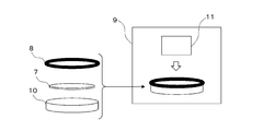
図1を参照して、水蒸気透過性測定ユニット10を用いた測定方法を説明する。
図1に示すように、水蒸気透過性測定ユニット10に試料7を設置し、試料封止材8で試料7の周囲を封止して装着する。これを恒温恒湿槽9の中に静置して、一定時間後に測定装置11で測定する。
この試料封止材8には、エチレン酢酸ビニル共重合体、ポリビニルブチラール、ブチルゴム、シリコーン樹脂、エポキシ樹脂等を用いることができ、好ましくはブチルゴム、シリコーン樹脂、エポキシ樹脂等を用いることができ、より好ましくはエポキシ樹脂を用いることができる。試料封止材8としてエポキシ樹脂を用いる場合には、試料封止材8の厚さ5mmとすると、水蒸気透過性は約0.14g/m2・dayである。試料封止材8の面積は試料7と比較して十分小さいため、試料封止材8を透過する水蒸気量は十分無視できる。
図1に示すように、水蒸気透過性測定ユニット10に試料7を設置し、試料封止材8で試料7の周囲を封止して装着する。これを恒温恒湿槽9の中に静置して、一定時間後に測定装置11で測定する。
この試料封止材8には、エチレン酢酸ビニル共重合体、ポリビニルブチラール、ブチルゴム、シリコーン樹脂、エポキシ樹脂等を用いることができ、好ましくはブチルゴム、シリコーン樹脂、エポキシ樹脂等を用いることができ、より好ましくはエポキシ樹脂を用いることができる。試料封止材8としてエポキシ樹脂を用いる場合には、試料封止材8の厚さ5mmとすると、水蒸気透過性は約0.14g/m2・dayである。試料封止材8の面積は試料7と比較して十分小さいため、試料封止材8を透過する水蒸気量は十分無視できる。
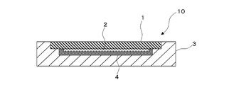
図2に示すように、水蒸気透過性測定ユニット10の第1の実施形態は、水蒸気検出部2を前述の高分子材料もしくは有機無機複合材料からなる水蒸気透過抑制部1で覆い、さらに金属膜からなる水蒸気透過阻止部4と樹脂からなる水蒸気透過阻止部3で封止した構造を持つ。水蒸気検出部2としては、カルシウム、マグネシウム、またはその合金のいずれかを含むものとするのがよい。水蒸気検出部2として、箔状に成形した場合には、水蒸気透過性を高感度に測定するという観点から、厚さが0.01μm以上、好ましくは0.05μm以上、より好ましくは0.1μm以上であり、透過量の高い水蒸気透過性を測定するという観点から、厚さが100μm以下、好ましくは10μm以下、より好ましくは1μm以下である。
水蒸気透過阻止部4の金属膜は、水蒸気透過性が少なくとも試料(図1参照)の水蒸気透過性より低いことが求められ、水蒸気を透過しない性質を有する金属膜を用いることによりこれを達成できる。このためには、金属膜には、ニッケル、アルミニウム、チタン、白金、銅、銀、金等を用いることができ、好ましくはアルミニウム、銅、金等を用いることができ、より好ましくはアルミニウムを用いることができる。水蒸気の透過を抑制するという観点から、厚さが0.01μm以上、好ましくは0.05μm以上、より好ましくは0.1μm以上であり、簡便に低コストで作製するという観点から、厚さが100μm以下、好ましくは10μm以下、より好ましくは1μm以下である。金属膜からなる水蒸気透過阻止部4を水蒸気検出部2の下面側に設けることにより、樹脂からなる水蒸気透過阻止部3では抑止できない微量な水蒸気の透過を金属膜からなる水蒸気透過阻止部4によって阻止することができ、より高精度な水蒸気透過性の測定を行うことが可能となる。
上記の樹脂からなる水蒸気透過阻止部3は、エチレン酢酸ビニル共重合体、ポリビニルブチラール、ブチルゴム、シリコーン樹脂、エポキシ樹脂等を用いることができ、好ましくはブチルゴム、シリコーン樹脂、エポキシ樹脂等を用いることができ、より好ましくはエポキシ樹脂を用いることができる。樹脂からなる水蒸気透過阻止部3としてエポキシ樹脂を用いる場合には、樹脂からなる水蒸気透過阻止部3を厚さ5mmに設定すると、水蒸気透過性は約0.14g/m2・dayである。
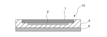
図3に示すように、水蒸気透過性測定ユニット10の第2の実施形態は、水蒸気検出部2の全面もしくは一部を水蒸気透過抑制部1で被覆し、さらに水蒸気検出部2の水蒸気透過抑制部1で被覆されていない表面全てを、樹脂からなる水蒸気透過阻止部3と水蒸気透過阻止部としてのガラス板5で封止する。
ガラス板5は、ソーダガラス、ホウケイ酸ガラス、石英ガラス、強化ガラス等を用いることができ、好ましくはホウケイ酸ガラス、強化ガラス等を用いることができ、より好ましくはホウケイ酸ガラスを用いることができる。
樹脂からなる水蒸気透過阻止部3の下面にガラス板5を設けることにより、水蒸気透過性測定ユニット下面から内部への水蒸気の透過をガラス板5によって阻止できる。
ガラス板5は、ソーダガラス、ホウケイ酸ガラス、石英ガラス、強化ガラス等を用いることができ、好ましくはホウケイ酸ガラス、強化ガラス等を用いることができ、より好ましくはホウケイ酸ガラスを用いることができる。
樹脂からなる水蒸気透過阻止部3の下面にガラス板5を設けることにより、水蒸気透過性測定ユニット下面から内部への水蒸気の透過をガラス板5によって阻止できる。
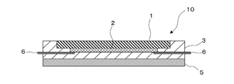
図4に示すように、水蒸気透過性測定ユニット10の第3の実施形態は、水蒸気検出部2の全面もしくは一部を水蒸気透過抑制部1で被覆し、電気抵抗測定用の電極6を水蒸気検出部2に接着して設置し、さらに水蒸気検出部2の水蒸気透過抑制部1で被覆されていない表面全てを樹脂からなる水蒸気透過阻止部3とガラス板5で封止する。
電極6を、樹脂からなる水蒸気透過阻止部3を貫通するように設けることにより、水蒸気検出部2の電気抵抗を測定する。水蒸気検出部2の電気抵抗を測定することにより、水蒸気透過による水蒸気検出部2の腐食量を導き、水蒸気透過性を測定できる。
電極6を、樹脂からなる水蒸気透過阻止部3を貫通するように設けることにより、水蒸気検出部2の電気抵抗を測定する。水蒸気検出部2の電気抵抗を測定することにより、水蒸気透過による水蒸気検出部2の腐食量を導き、水蒸気透過性を測定できる。
図5に示すように、水蒸気透過性測定ユニット10の第4の実施形態は、球状等の形状である水蒸気検出部2を水蒸気透過抑制部1で全部覆う場合(図5(a)参照。)、水蒸気検出部2の一部を水蒸気透過抑制部1で覆い残り全部を樹脂からなる水蒸気透過阻止部3で覆う場合(図5(b)参照。)、水蒸気検出部2に電極6を取り付けて水蒸気透過抑制部1で覆う場合(図5(c)参照。)がある。
すなわち、図5(a)に示すように、水蒸気検出部2を水蒸気透過抑制部1で全部覆う場合では、微量の水蒸気を高感度に測定できる。図5(b)に示すように、水蒸気検出部2の一部を水蒸気透過抑制部1で覆い残り全部を樹脂からなる水蒸気透過阻止部3で覆う場合では、水蒸気透過性測定ユニットの水蒸気測定感度を調節し、水蒸気透過性測定時の取扱いを簡便にする効果がある。図5(c)に示すように、水蒸気検出部2に電極6を取り付け、水蒸気透過抑制部1で覆う場合では、水蒸気透過による水蒸気検出部2の電気抵抗を測定する。水蒸気検出部2の電気抵抗を測定することにより、水蒸気透過による水蒸気検出部2の腐食量を求め、水蒸気透過性を測定できる。
すなわち、図5(a)に示すように、水蒸気検出部2を水蒸気透過抑制部1で全部覆う場合では、微量の水蒸気を高感度に測定できる。図5(b)に示すように、水蒸気検出部2の一部を水蒸気透過抑制部1で覆い残り全部を樹脂からなる水蒸気透過阻止部3で覆う場合では、水蒸気透過性測定ユニットの水蒸気測定感度を調節し、水蒸気透過性測定時の取扱いを簡便にする効果がある。図5(c)に示すように、水蒸気検出部2に電極6を取り付け、水蒸気透過抑制部1で覆う場合では、水蒸気透過による水蒸気検出部2の電気抵抗を測定する。水蒸気検出部2の電気抵抗を測定することにより、水蒸気透過による水蒸気検出部2の腐食量を求め、水蒸気透過性を測定できる。
以下に、水蒸気透過性測定ユニット10の各実施形態について、各実施形態において想定される水蒸気透過性の測定方法を示す。
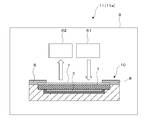
図6に示すように、第1の実施形態の測定装置11(11a)は、水蒸気透過性測定ユニット10の水蒸気透過抑制部1に試料7を取り付け、試料封止材8で封止をして、恒温恒湿槽9の内部に静置する。水蒸気検出部2の表面の光沢または腐食の画像を、発光装置61から照射された光による反射光もしくは画像を、反射光または画像の分析装置62で検出し、試料7の水蒸気透過性を測定する。
ここで用いる入射光は、ハロゲンランプ、水銀ランプ、UVランプ等から得られる赤外光、紫外光、もしくは可視光の任意の強度と波長の光を用いることができるが、好ましくは波長が400nm以上800nm以下、より好ましくは波長が500nm以上700nm以下の可視光を用いることができる。入射光の角度と反射光の検出角度は、任意の角度を用いることができるが、検出感度の観点から、好ましくは水蒸気透過性測定ユニット10の水蒸気透過抑制部の試料側表面に対して垂直であることが望ましい。ここで反射光および画像の測定は連続的でも適宜間を置いて行っても構わない。
ここで用いる入射光は、ハロゲンランプ、水銀ランプ、UVランプ等から得られる赤外光、紫外光、もしくは可視光の任意の強度と波長の光を用いることができるが、好ましくは波長が400nm以上800nm以下、より好ましくは波長が500nm以上700nm以下の可視光を用いることができる。入射光の角度と反射光の検出角度は、任意の角度を用いることができるが、検出感度の観点から、好ましくは水蒸気透過性測定ユニット10の水蒸気透過抑制部の試料側表面に対して垂直であることが望ましい。ここで反射光および画像の測定は連続的でも適宜間を置いて行っても構わない。
水蒸気透過性測定ユニット10を用いた水蒸気透過性の測定において、反射光または画像の分析装置62を用いて検出する方法は、水蒸気透過性測定ユニット10の水蒸気検出部2の面をカメラもしくはビデオカメラ等を有する反射光または画像の分析装置62で撮影し、コンピュータを用いた画像解析等の手段により得られた画像を解析し、水蒸気によって変色した水蒸気検出部の面積を測定して、水蒸気の透過量を測定する方法である。
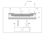
図7に示すように、第2の実施形態の測定装置11(11b)は、水蒸気透過性測定ユニット10の水蒸気透過抑制部1に試料7を取り付け、試料封止材8で試料7の周囲を封止して、恒温恒湿槽9の内部に静置する。水蒸気検出部2の腐食による開口部分を、発光装置71から照射された光による透過光もしくは画像を透過光または画像の分析装置72による画像分析で検出し、試料7の水蒸気透過性を測定する。
ここで用いる入射光は、ハロゲンランプ、水銀ランプ、UVランプ等から得られる赤外光、紫外光、もしくは可視光の任意の強度と波長の光を用いることができるが、好ましくは波長が400nm以上800nm以下、より好ましくは波長が500nm以上700nm以下の可視光を用いることができる。入射光の角度と透過光の検出角度は、任意の角度を用いることができるが、検出感度の観点から、好ましくは水蒸気透過性測定ユニット10の水蒸気透過抑制部の試料側表面に対して垂直であることが望ましい。ここで透過光および画像の測定は連続的でも適宜間を置いて行っても構わない。
水蒸気透過性測定ユニット10を用いた水蒸気透過性の測定において、透過光または画像の分析装置72を用いて検出する方法は、水蒸気透過性測定ユニット10の水蒸気検出部2の面をカメラもしくはビデオカメラ等を有する透過光または画像の分析装置72で撮影し、コンピュータを用いた画像解析等の手段により得られた画像を解析し、水蒸気によって変色した水蒸気検出部の面積を測定して、水蒸気の透過量を測定する方法である。
水蒸気透過量W(g)は、水蒸気によって変色した面積S(cm2)を用いて、(式2)から算出される。
水蒸気透過量W(g)は、水蒸気によって変色した面積S(cm2)を用いて、(式2)から算出される。
水蒸気透過性の測定条件としては、任意の温度と湿度を用いることができるが、測定温度については、標準的に測定に用いられる温度領域として、好ましくは25℃以上50℃以下、より好ましくは30℃以上40℃以下とするのがよい。測定湿度については、標準的に測定に用いられる湿度領域として、好ましくは50%(RH)以上90%(RH)以下、より好ましくは80%(RH)以上90%(RH)以下とするのがよい。
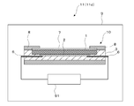
図8に示すように、第3の実施形態の測定装置11(11c)は、水蒸気透過性測定ユニット10の水蒸気透過抑制部1に測定試料を取り付け、試料封止材8で試料7の周囲を封止して、恒温恒湿槽9の内部に静置する。発光装置81から照射された光による、水蒸気検出部2の試料7と反対側の表面の光沢または腐食の画像を、反射光または画像の分析装置82で検出し、試料7の水蒸気透過性を測定する。
水蒸気透過性測定ユニット10を用いた水蒸気透過性の測定において、反射光または画像の分析装置82を用いて検出する方法は、水蒸気透過性測定ユニット10のガラス板5で封止された面をカメラもしくはビデオカメラ等を有する反射光または画像の分析装置82で撮影し、コンピュータを用いた画像解析等の手段により得られた画像を解析し、水蒸気によって腐食した水蒸気検出部の面積を測定して、水蒸気の透過量を測定する方法である。ここで画像解析の方法としては、一定時間ごとに解析を行う方法、もしくは連続的に変化を追跡して解析を行う方法と、任意の方法を用いることができる。
水蒸気透過性測定ユニット10を用いた水蒸気透過性の測定において、反射光または画像の分析装置82を用いて検出する方法は、水蒸気透過性測定ユニットの水蒸気検出部2の面をカメラもしくはビデオカメラ等を有する反射光または画像の分析装置82で撮影し、コンピュータを用いた画像解析等の手段により得られた画像を解析し、水蒸気によって変色した水蒸気検出部の面積を測定して、水蒸気の透過量を測定する方法である。
水蒸気透過量W(g)は、水蒸気によって変色した面積S(cm2)を用いて、(式2)から算出される。
水蒸気透過量W(g)は、水蒸気によって変色した面積S(cm2)を用いて、(式2)から算出される。
図6に示した上面側の反射光を検出する構成、図7に示した透過光を検出する構成、図8に示した下面側の反射光を検出する構成のそれぞれにおける特徴は次の通りである。
図6に示した測定装置11aでは、試料を通して測定光を透過および反射させる方法または画像解析によって水蒸気検出部2の腐食を測定することから、透明な試料を用いた場合に測定できる。
図7に示した測定装置11bでは、試料を通して測定光を透過させる方法または画像解析によって水蒸気検出部2の腐食を測定することから、画像解析装置ではなく汎用の分光装置を使用できる利点がある。
図8に示した測定装置11cでは、試料と反対側から測定光を入射してその反射光または画像解析によって水蒸気検出部2の腐食を測定する方法であることから、試料が透明でない場合にも適用できる。
図6に示した測定装置11aでは、試料を通して測定光を透過および反射させる方法または画像解析によって水蒸気検出部2の腐食を測定することから、透明な試料を用いた場合に測定できる。
図7に示した測定装置11bでは、試料を通して測定光を透過させる方法または画像解析によって水蒸気検出部2の腐食を測定することから、画像解析装置ではなく汎用の分光装置を使用できる利点がある。
図8に示した測定装置11cでは、試料と反対側から測定光を入射してその反射光または画像解析によって水蒸気検出部2の腐食を測定する方法であることから、試料が透明でない場合にも適用できる。
図9に示すように、第4の実施形態の測定装置11(11d)は、水蒸気透過性測定ユニット10の水蒸気透過抑制部1に試料7を載置し、試料封止材8で試料7の周囲を封止して、恒温恒湿槽9の内部に静置する。水蒸気検出部2に接続された電気抵抗測定用の電極6を用いて水蒸気検出部2の電気抵抗を電気抵抗測定装置91で測定し、試料7の水蒸気透過性を測定する。
水蒸気検出部2の電気抵抗を水蒸気透過性に換算する方法としては、次の手法がある。すなわち、あらかじめ水蒸気検出部が水との反応によって腐食した質量と電気抵抗の値との相関を測定しておく。この相関を元にして、水蒸気透過測定時に得られた電気抵抗の値から水蒸気検出部の腐食した質量WCa(g)を求める。
水蒸気検出部2の電気抵抗を水蒸気透過性に換算する方法としては、次の手法がある。すなわち、あらかじめ水蒸気検出部が水との反応によって腐食した質量と電気抵抗の値との相関を測定しておく。この相関を元にして、水蒸気透過測定時に得られた電気抵抗の値から水蒸気検出部の腐食した質量WCa(g)を求める。
上記測定装置11dは、水蒸気透過性測定ユニット10を用いて水蒸気透過性を測定する方法を実施するものであり、試料7と水蒸気透過抑制部1を通して透過した水蒸気によって水蒸気検出部2が腐食して生じる水蒸気検出部2の電気抵抗の変化を、電気抵抗測定用の電極6を用いて測定するものである。電気抵抗測定に際しては、電気抵抗測定用の電極6にインピーダンスアナライザー(例えば、Agilent社製4294A)もしくは抵抗測定器(例えば、Agilent社製E4982A)によって、電気抵抗測定用の電極6間の電気抵抗値を測定することによって得られる。
水蒸気透過性測定ユニット10を用いた電気抵抗測定によって水蒸気透過性を測定する方法では、電気抵抗値を数値として得て水蒸気透過性を測定することから定量的な解析をしやすいという利点がある。
水蒸気透過性測定ユニット10を用いた電気抵抗測定によって水蒸気透過性を測定する方法では、電気抵抗値を数値として得て水蒸気透過性を測定することから定量的な解析をしやすいという利点がある。
図10に示すように、第5の実施形態の測定装置11(11e)は、水蒸気透過性測定ユニット10を容器状の試料7の内部に入れ、試料7にふたをした後、恒温恒湿槽9の内部に静置する。水蒸気検出部(図示せず)の腐食を、光の反射もしくは透過もしくは電極を用いた電気抵抗から検出し、水蒸気透過度を測定する。測定には、上記説明した反射光または画像の分析装置62、82、透過光または画像の分析装置72、電気抵抗測定装置91を用いる。
上記各測定装置11で試料7を測定した場合には、従来の測定方法で測定した場合と比較して、簡便な操作によって高い感度の測定結果を得ることができる。
すなわち、従来の方法においては試料を測定装置に設置する際には、水蒸気を装置内部に取り込まないように、真空装置や水蒸気を除去するための加熱を行う必要があり、測定操作が極めて煩雑になっていた。一方、本手法においては水蒸気透過抑制部を用いることにより従来の金属カルシウム法で必要とされた煩雑な操作をすることなく、高感度な水蒸気の透過性の測定を行うことが可能である。
すなわち、従来の方法においては試料を測定装置に設置する際には、水蒸気を装置内部に取り込まないように、真空装置や水蒸気を除去するための加熱を行う必要があり、測定操作が極めて煩雑になっていた。一方、本手法においては水蒸気透過抑制部を用いることにより従来の金属カルシウム法で必要とされた煩雑な操作をすることなく、高感度な水蒸気の透過性の測定を行うことが可能である。
水蒸気透過性の高感度な測定とは、水蒸気の透過度が1×10⁻²g/m2・day以下の値を測定できることを指す。これを判定するためにはまず水蒸気透過性を持たない基準試料の水蒸気透過性の測定試験を行い、水蒸気透過性が1×10-4g/m2・dayより小さいことを確認する。これにより、試料の水蒸気透過性を測定した時に1×10-2g/m2・day以下の値を高感度に測定できるとの判定を行うことができる。水蒸気透過性を持たない基準試料としては、ニッケル、アルミニウム、チタン、白金、銅、銀、金等を用いることができ、好ましくはアルミニウム、銅、金等を用いることができ、より好ましくはアルミニウムを用いることができる。水蒸気透過性を持たない基準試料の厚さは0.05μm以上、好ましくは0.1μm以上、より好ましくは0.5μm以上である。
水蒸気透過性測定ユニットを用いることにより、バリアフィルム等の試料の水蒸気透過特性を高感度、簡便、かつ安価に評価できるので、水蒸気阻止膜の開発や製品出荷前検査が効率化される。こうして開発・製造された水蒸気阻止膜は太陽電池や有機発光デバイスといった有機エレクトロニクス素子に用いられ、それらの製品寿命改善につながる。また、食品包装に用いることで、瓶や缶に代わって長期間の保存可能で内容物を視認できる透明包装が可能となる。
本発明をその実施形態および実施例とともに説明したが、我々は特に指定しない限り我々の発明を説明のどの細部においても限定しようとするものではなく、添付の請求の範囲に示した発明の精神と範囲に反することなく幅広く解釈されるべきであると考える。
本願は、2013年1月31日に日本国で特許出願された特願2013-017823に基づく優先権を主張するものであり、これらはここに参照してその内容を本明細書の記載の一部として取り込む。
1 水蒸気透過抑制部
2 水蒸気検出部
3 水蒸気透過阻止部
4 水蒸気透過阻止部
5 ガラス板
6 電気抵抗測定電極
7 試料
8 試料封止材
9 恒温恒湿槽
10 水蒸気透過性測定ユニット
11 測定装置
61 発光装置
62 反射光または画像の分析装置
71 発光装置
72 透過光または画像の分析装置
81 発光装置
82 反射光または画像の分析装置
91 電気抵抗測定装置
2 水蒸気検出部
3 水蒸気透過阻止部
4 水蒸気透過阻止部
5 ガラス板
6 電気抵抗測定電極
7 試料
8 試料封止材
9 恒温恒湿槽
10 水蒸気透過性測定ユニット
11 測定装置
61 発光装置
62 反射光または画像の分析装置
71 発光装置
72 透過光または画像の分析装置
81 発光装置
82 反射光または画像の分析装置
91 電気抵抗測定装置
Claims (10)
- 水蒸気を検出する水蒸気検出部と水蒸気の透過を抑制する水蒸気透過抑制部を備え、前記水蒸気検出部の外表面の全面が前記水蒸気透過抑制部により覆われてなる水蒸気透過性測定ユニット。
- 水蒸気を検出する水蒸気検出部と水蒸気の透過を抑制する水蒸気透過抑制部と水蒸気の透過を阻止する水蒸気透過阻止部とを備え、前記水蒸気検出部の外表面の一部を前記水蒸気透過抑制部により、前記水蒸気検出部の外表面の残り全部を前記水蒸気透過阻止部により覆われてなる水蒸気透過性測定ユニット。
- 前記水蒸気検出部に電極を接着して設置してなる請求項1または2の水蒸気透過性測定ユニット。
- 前記水蒸気透過抑制部の水蒸気透過性が1g/m2・day以下である請求項1から3のいずれか1項に記載の水蒸気透過性測定ユニット。
- 前記水蒸気透過抑制部が高分子材料または有機無機複合体である請求項1から4のいずれか1項に記載の水蒸気透過性測定ユニット。
- 前記水蒸気検出部が、カルシウム、マグネシウム、またはその合金のいずれかを含む請求項1から5のいずれか1項に記載の水蒸気透過性測定ユニット。
- 請求項1から6のいずれか1項に記載の水蒸気透過性測定ユニットを用いた水蒸気透過性の測定方法であって、
前記水蒸気検出部上に前記水蒸気透過抑制部を介して試料を配置する水蒸気透過性の測定方法。 - 請求項7に記載の水蒸気透過性の測定方法であって、
前記試料の水蒸気透過性が前記水蒸気透過抑制部の水蒸気透過性の3000分の1倍以上かつ1倍以下である水蒸気透過性の測定方法。 - 前記請求項7または8に記載の水蒸気透過性の測定方法であって、
前記水蒸気透過性測定ユニットを、前記試料を取り付けて一定の湿度下において暴露し、前記水蒸気検出部の腐食量を用いて前記試料の水蒸気透過度を測定する水蒸気透過性の測定方法。 - 前記請求項3に記載の水蒸気透過性測定ユニットを用いた水蒸気透過性の測定方法であって、
前記水蒸気透過性測定ユニットを、試料を取り付けて一定の湿度下において暴露し、前記水蒸気検出部の電気伝導度の変化を用いて前記試料の水蒸気透過度を測定する水蒸気透過性の測定方法。
Priority Applications (1)
| Application Number | Priority Date | Filing Date | Title |
|---|---|---|---|
| JP2014559757A JP6086616B2 (ja) | 2013-01-31 | 2014-01-30 | 水蒸気透過性測定ユニットおよび水蒸気透過性測定方法 |
Applications Claiming Priority (2)
| Application Number | Priority Date | Filing Date | Title |
|---|---|---|---|
| JP2013-017823 | 2013-01-31 | ||
| JP2013017823 | 2013-01-31 |
Publications (1)
| Publication Number | Publication Date |
|---|---|
| WO2014119690A1 true WO2014119690A1 (ja) | 2014-08-07 |
Family
ID=51262395
Family Applications (1)
| Application Number | Title | Priority Date | Filing Date |
|---|---|---|---|
| PCT/JP2014/052167 Ceased WO2014119690A1 (ja) | 2013-01-31 | 2014-01-30 | 水蒸気透過性測定ユニットおよび水蒸気透過性測定方法 |
Country Status (2)
| Country | Link |
|---|---|
| JP (1) | JP6086616B2 (ja) |
| WO (1) | WO2014119690A1 (ja) |
Cited By (6)
| Publication number | Priority date | Publication date | Assignee | Title |
|---|---|---|---|---|
| JP2015038439A (ja) * | 2013-08-19 | 2015-02-26 | 凸版印刷株式会社 | ガス透過性試験片、ガス透過性試験片作製装置、及びガスバリア透過性評価装置 |
| CN105403476A (zh) * | 2015-12-23 | 2016-03-16 | 济南兰光机电技术有限公司 | 一种多腔体称重法透湿测试系统及测试方法 |
| KR20180108680A (ko) * | 2016-02-03 | 2018-10-04 | 내셔날 인스티튜트 오브 어드밴스드 인더스트리얼 사이언스 앤드 테크놀로지 | 표준 가스 배리어 필름 |
| EP3669168A1 (en) * | 2017-08-18 | 2020-06-24 | Oxford University Innovation Limited | Water vapour permeation |
| CN116879126A (zh) * | 2023-06-20 | 2023-10-13 | 绍兴市质量技术监督检测院 | 一种环境实验箱及其配套的水蒸气透过率测定方法 |
| EP4314763A4 (en) * | 2021-03-26 | 2025-02-19 | Stora Enso Oyj | METHOD AND DEVICE FOR ASSESSING THE PERMEABILITY OF A SAMPLE |
Families Citing this family (1)
| Publication number | Priority date | Publication date | Assignee | Title |
|---|---|---|---|---|
| KR102868796B1 (ko) * | 2020-09-11 | 2025-10-02 | 현대자동차주식회사 | 연료전지용 기체확산층의 물투과도 측정장치 |
Citations (5)
| Publication number | Priority date | Publication date | Assignee | Title |
|---|---|---|---|---|
| JP2004333127A (ja) * | 2002-04-05 | 2004-11-25 | Sumitomo Bakelite Co Ltd | 水蒸気バリア性評価用セルおよび水蒸気バリア性評価方法 |
| JP2005283561A (ja) * | 2004-03-04 | 2005-10-13 | Sumitomo Bakelite Co Ltd | 水蒸気透過度測定装置 |
| JP2007537421A (ja) * | 2004-03-31 | 2007-12-20 | エージェンシー フォー サイエンス,テクノロジー アンド リサーチ | 試験材料のガス透過率を測定するためのセンサ |
| JP2011047680A (ja) * | 2009-08-25 | 2011-03-10 | Toppan Printing Co Ltd | 水蒸気透過度測定方法および装置 |
| JP2012189359A (ja) * | 2011-03-09 | 2012-10-04 | Toppan Printing Co Ltd | ガス透過性試験片及びガス透過性評価方法 |
-
2014
- 2014-01-30 WO PCT/JP2014/052167 patent/WO2014119690A1/ja not_active Ceased
- 2014-01-30 JP JP2014559757A patent/JP6086616B2/ja not_active Expired - Fee Related
Patent Citations (5)
| Publication number | Priority date | Publication date | Assignee | Title |
|---|---|---|---|---|
| JP2004333127A (ja) * | 2002-04-05 | 2004-11-25 | Sumitomo Bakelite Co Ltd | 水蒸気バリア性評価用セルおよび水蒸気バリア性評価方法 |
| JP2005283561A (ja) * | 2004-03-04 | 2005-10-13 | Sumitomo Bakelite Co Ltd | 水蒸気透過度測定装置 |
| JP2007537421A (ja) * | 2004-03-31 | 2007-12-20 | エージェンシー フォー サイエンス,テクノロジー アンド リサーチ | 試験材料のガス透過率を測定するためのセンサ |
| JP2011047680A (ja) * | 2009-08-25 | 2011-03-10 | Toppan Printing Co Ltd | 水蒸気透過度測定方法および装置 |
| JP2012189359A (ja) * | 2011-03-09 | 2012-10-04 | Toppan Printing Co Ltd | ガス透過性試験片及びガス透過性評価方法 |
Cited By (8)
| Publication number | Priority date | Publication date | Assignee | Title |
|---|---|---|---|---|
| JP2015038439A (ja) * | 2013-08-19 | 2015-02-26 | 凸版印刷株式会社 | ガス透過性試験片、ガス透過性試験片作製装置、及びガスバリア透過性評価装置 |
| CN105403476A (zh) * | 2015-12-23 | 2016-03-16 | 济南兰光机电技术有限公司 | 一种多腔体称重法透湿测试系统及测试方法 |
| KR20180108680A (ko) * | 2016-02-03 | 2018-10-04 | 내셔날 인스티튜트 오브 어드밴스드 인더스트리얼 사이언스 앤드 테크놀로지 | 표준 가스 배리어 필름 |
| JPWO2017135292A1 (ja) * | 2016-02-03 | 2018-12-06 | 国立研究開発法人産業技術総合研究所 | 標準ガスバリアフィルム |
| KR102219619B1 (ko) | 2016-02-03 | 2021-02-23 | 내셔날 인스티튜트 오브 어드밴스드 인더스트리얼 사이언스 앤드 테크놀로지 | 표준 가스 배리어 필름 |
| EP3669168A1 (en) * | 2017-08-18 | 2020-06-24 | Oxford University Innovation Limited | Water vapour permeation |
| EP4314763A4 (en) * | 2021-03-26 | 2025-02-19 | Stora Enso Oyj | METHOD AND DEVICE FOR ASSESSING THE PERMEABILITY OF A SAMPLE |
| CN116879126A (zh) * | 2023-06-20 | 2023-10-13 | 绍兴市质量技术监督检测院 | 一种环境实验箱及其配套的水蒸气透过率测定方法 |
Also Published As
| Publication number | Publication date |
|---|---|
| JP6086616B2 (ja) | 2017-03-01 |
| JPWO2014119690A1 (ja) | 2017-01-26 |
Similar Documents
| Publication | Publication Date | Title |
|---|---|---|
| JP6086616B2 (ja) | 水蒸気透過性測定ユニットおよび水蒸気透過性測定方法 | |
| US7117720B2 (en) | Method for measuring a permeation rate, a test and an apparatus for measuring and testing | |
| JP6345421B2 (ja) | ガスバリア性評価装置および評価方法 | |
| US7791729B2 (en) | Attenuated total reflection probe and spectrometer therewith | |
| Abdellatief et al. | Comparison of new dynamic accumulation method for measuring oxygen transmission rate of packaging against the steady‐state method described by ASTM D3985 | |
| JP6304745B2 (ja) | ガスバリア性評価装置および評価方法 | |
| JP2014160069A (ja) | バリア材の透過度を測定する方法及び装置 | |
| JP2005283561A (ja) | 水蒸気透過度測定装置 | |
| CN111044431A (zh) | 薄膜水汽透过率的测试装置及测试方法 | |
| EP3669168A1 (en) | Water vapour permeation | |
| Pan et al. | Water vapor transmission rate measurement for moisture barriers using infrared imaging | |
| JPWO2018155678A1 (ja) | ガスバリア性評価装置およびガスバリア性評価方法 | |
| JP6299751B2 (ja) | ガスバリアーフィルムの水蒸気透過度評価方法と評価システム及びガスバリアーフィルムの製造方法 | |
| Suzuki et al. | Development of reliable technique for evaluating the properties of water vapor barriers | |
| JP2013003028A (ja) | 測定装置および測定方法 | |
| Yeo et al. | Wearable Image‐Based Colorimetric Sensor for Real‐Time Gas Detection with High Chromaticity | |
| JP6635033B2 (ja) | 水蒸気透過度評価方法及び水蒸気透過度評価装置 | |
| JP2005241316A (ja) | 金属腐食度測定方法および装置 | |
| JP7656677B2 (ja) | ガス透過セル、試料固定治具、ガス透過度測定装置、及びガス透過度測定方法 | |
| CN112858387A (zh) | 一种可过滤气体的露点检测装置 | |
| JP5724254B2 (ja) | ガス透過性評価方法およびガス透過性評価装置 | |
| Herbst et al. | Helium transmission rate as a rapid and reliable method for assessing the water vapour transmission rate of transparent PET‐SiOx barrier foils | |
| US20090116021A1 (en) | Method and apparatus for determining composition and concentration of contaminants on a film encapsulated in a plasma display panel | |
| TWI661193B (zh) | 無銀電極式之水氣與氧氣穿透感測結構 | |
| CN105372210B (zh) | 氢传感器、氢检测系统以及具有氢检测系统的电气装置 |
Legal Events
| Date | Code | Title | Description |
|---|---|---|---|
| 121 | Ep: the epo has been informed by wipo that ep was designated in this application |
Ref document number: 14746352 Country of ref document: EP Kind code of ref document: A1 |
|
| ENP | Entry into the national phase |
Ref document number: 2014559757 Country of ref document: JP Kind code of ref document: A |
|
| NENP | Non-entry into the national phase |
Ref country code: DE |
|
| 122 | Ep: pct application non-entry in european phase |
Ref document number: 14746352 Country of ref document: EP Kind code of ref document: A1 |