WO2014119088A1 - 自動変速機の制御装置 - Google Patents
自動変速機の制御装置 Download PDFInfo
- Publication number
- WO2014119088A1 WO2014119088A1 PCT/JP2013/080736 JP2013080736W WO2014119088A1 WO 2014119088 A1 WO2014119088 A1 WO 2014119088A1 JP 2013080736 W JP2013080736 W JP 2013080736W WO 2014119088 A1 WO2014119088 A1 WO 2014119088A1
- Authority
- WO
- WIPO (PCT)
- Prior art keywords
- determination
- mode
- automatic transmission
- motor
- engagement
- Prior art date
Links
Images


Classifications
-
- B—PERFORMING OPERATIONS; TRANSPORTING
- B60—VEHICLES IN GENERAL
- B60W—CONJOINT CONTROL OF VEHICLE SUB-UNITS OF DIFFERENT TYPE OR DIFFERENT FUNCTION; CONTROL SYSTEMS SPECIALLY ADAPTED FOR HYBRID VEHICLES; ROAD VEHICLE DRIVE CONTROL SYSTEMS FOR PURPOSES NOT RELATED TO THE CONTROL OF A PARTICULAR SUB-UNIT
- B60W10/00—Conjoint control of vehicle sub-units of different type or different function
- B60W10/10—Conjoint control of vehicle sub-units of different type or different function including control of change-speed gearings
-
- B—PERFORMING OPERATIONS; TRANSPORTING
- B60—VEHICLES IN GENERAL
- B60W—CONJOINT CONTROL OF VEHICLE SUB-UNITS OF DIFFERENT TYPE OR DIFFERENT FUNCTION; CONTROL SYSTEMS SPECIALLY ADAPTED FOR HYBRID VEHICLES; ROAD VEHICLE DRIVE CONTROL SYSTEMS FOR PURPOSES NOT RELATED TO THE CONTROL OF A PARTICULAR SUB-UNIT
- B60W20/00—Control systems specially adapted for hybrid vehicles
- B60W20/40—Controlling the engagement or disengagement of prime movers, e.g. for transition between prime movers
-
- B—PERFORMING OPERATIONS; TRANSPORTING
- B60—VEHICLES IN GENERAL
- B60K—ARRANGEMENT OR MOUNTING OF PROPULSION UNITS OR OF TRANSMISSIONS IN VEHICLES; ARRANGEMENT OR MOUNTING OF PLURAL DIVERSE PRIME-MOVERS IN VEHICLES; AUXILIARY DRIVES FOR VEHICLES; INSTRUMENTATION OR DASHBOARDS FOR VEHICLES; ARRANGEMENTS IN CONNECTION WITH COOLING, AIR INTAKE, GAS EXHAUST OR FUEL SUPPLY OF PROPULSION UNITS IN VEHICLES
- B60K6/00—Arrangement or mounting of plural diverse prime-movers for mutual or common propulsion, e.g. hybrid propulsion systems comprising electric motors and internal combustion engines ; Control systems therefor, i.e. systems controlling two or more prime movers, or controlling one of these prime movers and any of the transmission, drive or drive units Informative references: mechanical gearings with secondary electric drive F16H3/72; arrangements for handling mechanical energy structurally associated with the dynamo-electric machine H02K7/00; machines comprising structurally interrelated motor and generator parts H02K51/00; dynamo-electric machines not otherwise provided for in H02K see H02K99/00
- B60K6/20—Arrangement or mounting of plural diverse prime-movers for mutual or common propulsion, e.g. hybrid propulsion systems comprising electric motors and internal combustion engines ; Control systems therefor, i.e. systems controlling two or more prime movers, or controlling one of these prime movers and any of the transmission, drive or drive units Informative references: mechanical gearings with secondary electric drive F16H3/72; arrangements for handling mechanical energy structurally associated with the dynamo-electric machine H02K7/00; machines comprising structurally interrelated motor and generator parts H02K51/00; dynamo-electric machines not otherwise provided for in H02K see H02K99/00 the prime-movers consisting of electric motors and internal combustion engines, e.g. HEVs
- B60K6/42—Arrangement or mounting of plural diverse prime-movers for mutual or common propulsion, e.g. hybrid propulsion systems comprising electric motors and internal combustion engines ; Control systems therefor, i.e. systems controlling two or more prime movers, or controlling one of these prime movers and any of the transmission, drive or drive units Informative references: mechanical gearings with secondary electric drive F16H3/72; arrangements for handling mechanical energy structurally associated with the dynamo-electric machine H02K7/00; machines comprising structurally interrelated motor and generator parts H02K51/00; dynamo-electric machines not otherwise provided for in H02K see H02K99/00 the prime-movers consisting of electric motors and internal combustion engines, e.g. HEVs characterised by the architecture of the hybrid electric vehicle
- B60K6/48—Parallel type
-
- B—PERFORMING OPERATIONS; TRANSPORTING
- B60—VEHICLES IN GENERAL
- B60K—ARRANGEMENT OR MOUNTING OF PROPULSION UNITS OR OF TRANSMISSIONS IN VEHICLES; ARRANGEMENT OR MOUNTING OF PLURAL DIVERSE PRIME-MOVERS IN VEHICLES; AUXILIARY DRIVES FOR VEHICLES; INSTRUMENTATION OR DASHBOARDS FOR VEHICLES; ARRANGEMENTS IN CONNECTION WITH COOLING, AIR INTAKE, GAS EXHAUST OR FUEL SUPPLY OF PROPULSION UNITS IN VEHICLES
- B60K6/00—Arrangement or mounting of plural diverse prime-movers for mutual or common propulsion, e.g. hybrid propulsion systems comprising electric motors and internal combustion engines ; Control systems therefor, i.e. systems controlling two or more prime movers, or controlling one of these prime movers and any of the transmission, drive or drive units Informative references: mechanical gearings with secondary electric drive F16H3/72; arrangements for handling mechanical energy structurally associated with the dynamo-electric machine H02K7/00; machines comprising structurally interrelated motor and generator parts H02K51/00; dynamo-electric machines not otherwise provided for in H02K see H02K99/00
- B60K6/20—Arrangement or mounting of plural diverse prime-movers for mutual or common propulsion, e.g. hybrid propulsion systems comprising electric motors and internal combustion engines ; Control systems therefor, i.e. systems controlling two or more prime movers, or controlling one of these prime movers and any of the transmission, drive or drive units Informative references: mechanical gearings with secondary electric drive F16H3/72; arrangements for handling mechanical energy structurally associated with the dynamo-electric machine H02K7/00; machines comprising structurally interrelated motor and generator parts H02K51/00; dynamo-electric machines not otherwise provided for in H02K see H02K99/00 the prime-movers consisting of electric motors and internal combustion engines, e.g. HEVs
- B60K6/22—Arrangement or mounting of plural diverse prime-movers for mutual or common propulsion, e.g. hybrid propulsion systems comprising electric motors and internal combustion engines ; Control systems therefor, i.e. systems controlling two or more prime movers, or controlling one of these prime movers and any of the transmission, drive or drive units Informative references: mechanical gearings with secondary electric drive F16H3/72; arrangements for handling mechanical energy structurally associated with the dynamo-electric machine H02K7/00; machines comprising structurally interrelated motor and generator parts H02K51/00; dynamo-electric machines not otherwise provided for in H02K see H02K99/00 the prime-movers consisting of electric motors and internal combustion engines, e.g. HEVs characterised by apparatus, components or means specially adapted for HEVs
- B60K6/38—Arrangement or mounting of plural diverse prime-movers for mutual or common propulsion, e.g. hybrid propulsion systems comprising electric motors and internal combustion engines ; Control systems therefor, i.e. systems controlling two or more prime movers, or controlling one of these prime movers and any of the transmission, drive or drive units Informative references: mechanical gearings with secondary electric drive F16H3/72; arrangements for handling mechanical energy structurally associated with the dynamo-electric machine H02K7/00; machines comprising structurally interrelated motor and generator parts H02K51/00; dynamo-electric machines not otherwise provided for in H02K see H02K99/00 the prime-movers consisting of electric motors and internal combustion engines, e.g. HEVs characterised by apparatus, components or means specially adapted for HEVs characterised by the driveline clutches
- B60K6/387—Actuated clutches, i.e. clutches engaged or disengaged by electric, hydraulic or mechanical actuating means
-
- B—PERFORMING OPERATIONS; TRANSPORTING
- B60—VEHICLES IN GENERAL
- B60K—ARRANGEMENT OR MOUNTING OF PROPULSION UNITS OR OF TRANSMISSIONS IN VEHICLES; ARRANGEMENT OR MOUNTING OF PLURAL DIVERSE PRIME-MOVERS IN VEHICLES; AUXILIARY DRIVES FOR VEHICLES; INSTRUMENTATION OR DASHBOARDS FOR VEHICLES; ARRANGEMENTS IN CONNECTION WITH COOLING, AIR INTAKE, GAS EXHAUST OR FUEL SUPPLY OF PROPULSION UNITS IN VEHICLES
- B60K6/00—Arrangement or mounting of plural diverse prime-movers for mutual or common propulsion, e.g. hybrid propulsion systems comprising electric motors and internal combustion engines ; Control systems therefor, i.e. systems controlling two or more prime movers, or controlling one of these prime movers and any of the transmission, drive or drive units Informative references: mechanical gearings with secondary electric drive F16H3/72; arrangements for handling mechanical energy structurally associated with the dynamo-electric machine H02K7/00; machines comprising structurally interrelated motor and generator parts H02K51/00; dynamo-electric machines not otherwise provided for in H02K see H02K99/00
- B60K6/20—Arrangement or mounting of plural diverse prime-movers for mutual or common propulsion, e.g. hybrid propulsion systems comprising electric motors and internal combustion engines ; Control systems therefor, i.e. systems controlling two or more prime movers, or controlling one of these prime movers and any of the transmission, drive or drive units Informative references: mechanical gearings with secondary electric drive F16H3/72; arrangements for handling mechanical energy structurally associated with the dynamo-electric machine H02K7/00; machines comprising structurally interrelated motor and generator parts H02K51/00; dynamo-electric machines not otherwise provided for in H02K see H02K99/00 the prime-movers consisting of electric motors and internal combustion engines, e.g. HEVs
- B60K6/50—Architecture of the driveline characterised by arrangement or kind of transmission units
- B60K6/54—Transmission for changing ratio
- B60K6/547—Transmission for changing ratio the transmission being a stepped gearing
-
- B—PERFORMING OPERATIONS; TRANSPORTING
- B60—VEHICLES IN GENERAL
- B60W—CONJOINT CONTROL OF VEHICLE SUB-UNITS OF DIFFERENT TYPE OR DIFFERENT FUNCTION; CONTROL SYSTEMS SPECIALLY ADAPTED FOR HYBRID VEHICLES; ROAD VEHICLE DRIVE CONTROL SYSTEMS FOR PURPOSES NOT RELATED TO THE CONTROL OF A PARTICULAR SUB-UNIT
- B60W10/00—Conjoint control of vehicle sub-units of different type or different function
- B60W10/02—Conjoint control of vehicle sub-units of different type or different function including control of driveline clutches
-
- B—PERFORMING OPERATIONS; TRANSPORTING
- B60—VEHICLES IN GENERAL
- B60W—CONJOINT CONTROL OF VEHICLE SUB-UNITS OF DIFFERENT TYPE OR DIFFERENT FUNCTION; CONTROL SYSTEMS SPECIALLY ADAPTED FOR HYBRID VEHICLES; ROAD VEHICLE DRIVE CONTROL SYSTEMS FOR PURPOSES NOT RELATED TO THE CONTROL OF A PARTICULAR SUB-UNIT
- B60W10/00—Conjoint control of vehicle sub-units of different type or different function
- B60W10/04—Conjoint control of vehicle sub-units of different type or different function including control of propulsion units
- B60W10/06—Conjoint control of vehicle sub-units of different type or different function including control of propulsion units including control of combustion engines
-
- B—PERFORMING OPERATIONS; TRANSPORTING
- B60—VEHICLES IN GENERAL
- B60W—CONJOINT CONTROL OF VEHICLE SUB-UNITS OF DIFFERENT TYPE OR DIFFERENT FUNCTION; CONTROL SYSTEMS SPECIALLY ADAPTED FOR HYBRID VEHICLES; ROAD VEHICLE DRIVE CONTROL SYSTEMS FOR PURPOSES NOT RELATED TO THE CONTROL OF A PARTICULAR SUB-UNIT
- B60W10/00—Conjoint control of vehicle sub-units of different type or different function
- B60W10/04—Conjoint control of vehicle sub-units of different type or different function including control of propulsion units
- B60W10/08—Conjoint control of vehicle sub-units of different type or different function including control of propulsion units including control of electric propulsion units, e.g. motors or generators
-
- B—PERFORMING OPERATIONS; TRANSPORTING
- B60—VEHICLES IN GENERAL
- B60W—CONJOINT CONTROL OF VEHICLE SUB-UNITS OF DIFFERENT TYPE OR DIFFERENT FUNCTION; CONTROL SYSTEMS SPECIALLY ADAPTED FOR HYBRID VEHICLES; ROAD VEHICLE DRIVE CONTROL SYSTEMS FOR PURPOSES NOT RELATED TO THE CONTROL OF A PARTICULAR SUB-UNIT
- B60W10/00—Conjoint control of vehicle sub-units of different type or different function
- B60W10/10—Conjoint control of vehicle sub-units of different type or different function including control of change-speed gearings
- B60W10/11—Stepped gearings
- B60W10/115—Stepped gearings with planetary gears
-
- B—PERFORMING OPERATIONS; TRANSPORTING
- B60—VEHICLES IN GENERAL
- B60W—CONJOINT CONTROL OF VEHICLE SUB-UNITS OF DIFFERENT TYPE OR DIFFERENT FUNCTION; CONTROL SYSTEMS SPECIALLY ADAPTED FOR HYBRID VEHICLES; ROAD VEHICLE DRIVE CONTROL SYSTEMS FOR PURPOSES NOT RELATED TO THE CONTROL OF A PARTICULAR SUB-UNIT
- B60W20/00—Control systems specially adapted for hybrid vehicles
-
- B—PERFORMING OPERATIONS; TRANSPORTING
- B60—VEHICLES IN GENERAL
- B60W—CONJOINT CONTROL OF VEHICLE SUB-UNITS OF DIFFERENT TYPE OR DIFFERENT FUNCTION; CONTROL SYSTEMS SPECIALLY ADAPTED FOR HYBRID VEHICLES; ROAD VEHICLE DRIVE CONTROL SYSTEMS FOR PURPOSES NOT RELATED TO THE CONTROL OF A PARTICULAR SUB-UNIT
- B60W30/00—Purposes of road vehicle drive control systems not related to the control of a particular sub-unit, e.g. of systems using conjoint control of vehicle sub-units, or advanced driver assistance systems for ensuring comfort, stability and safety or drive control systems for propelling or retarding the vehicle
- B60W30/18—Propelling the vehicle
- B60W30/18009—Propelling the vehicle related to particular drive situations
- B60W30/18027—Drive off, accelerating from standstill
-
- B—PERFORMING OPERATIONS; TRANSPORTING
- B60—VEHICLES IN GENERAL
- B60W—CONJOINT CONTROL OF VEHICLE SUB-UNITS OF DIFFERENT TYPE OR DIFFERENT FUNCTION; CONTROL SYSTEMS SPECIALLY ADAPTED FOR HYBRID VEHICLES; ROAD VEHICLE DRIVE CONTROL SYSTEMS FOR PURPOSES NOT RELATED TO THE CONTROL OF A PARTICULAR SUB-UNIT
- B60W2510/00—Input parameters relating to a particular sub-units
- B60W2510/02—Clutches
- B60W2510/0208—Clutch engagement state, e.g. engaged or disengaged
-
- B—PERFORMING OPERATIONS; TRANSPORTING
- B60—VEHICLES IN GENERAL
- B60W—CONJOINT CONTROL OF VEHICLE SUB-UNITS OF DIFFERENT TYPE OR DIFFERENT FUNCTION; CONTROL SYSTEMS SPECIALLY ADAPTED FOR HYBRID VEHICLES; ROAD VEHICLE DRIVE CONTROL SYSTEMS FOR PURPOSES NOT RELATED TO THE CONTROL OF A PARTICULAR SUB-UNIT
- B60W2510/00—Input parameters relating to a particular sub-units
- B60W2510/06—Combustion engines, Gas turbines
-
- B—PERFORMING OPERATIONS; TRANSPORTING
- B60—VEHICLES IN GENERAL
- B60W—CONJOINT CONTROL OF VEHICLE SUB-UNITS OF DIFFERENT TYPE OR DIFFERENT FUNCTION; CONTROL SYSTEMS SPECIALLY ADAPTED FOR HYBRID VEHICLES; ROAD VEHICLE DRIVE CONTROL SYSTEMS FOR PURPOSES NOT RELATED TO THE CONTROL OF A PARTICULAR SUB-UNIT
- B60W2510/00—Input parameters relating to a particular sub-units
- B60W2510/10—Change speed gearings
- B60W2510/1005—Transmission ratio engaged
-
- B—PERFORMING OPERATIONS; TRANSPORTING
- B60—VEHICLES IN GENERAL
- B60W—CONJOINT CONTROL OF VEHICLE SUB-UNITS OF DIFFERENT TYPE OR DIFFERENT FUNCTION; CONTROL SYSTEMS SPECIALLY ADAPTED FOR HYBRID VEHICLES; ROAD VEHICLE DRIVE CONTROL SYSTEMS FOR PURPOSES NOT RELATED TO THE CONTROL OF A PARTICULAR SUB-UNIT
- B60W2510/00—Input parameters relating to a particular sub-units
- B60W2510/10—Change speed gearings
- B60W2510/1015—Input shaft speed, e.g. turbine speed
-
- B—PERFORMING OPERATIONS; TRANSPORTING
- B60—VEHICLES IN GENERAL
- B60W—CONJOINT CONTROL OF VEHICLE SUB-UNITS OF DIFFERENT TYPE OR DIFFERENT FUNCTION; CONTROL SYSTEMS SPECIALLY ADAPTED FOR HYBRID VEHICLES; ROAD VEHICLE DRIVE CONTROL SYSTEMS FOR PURPOSES NOT RELATED TO THE CONTROL OF A PARTICULAR SUB-UNIT
- B60W2710/00—Output or target parameters relating to a particular sub-units
- B60W2710/02—Clutches
- B60W2710/021—Clutch engagement state
-
- B—PERFORMING OPERATIONS; TRANSPORTING
- B60—VEHICLES IN GENERAL
- B60W—CONJOINT CONTROL OF VEHICLE SUB-UNITS OF DIFFERENT TYPE OR DIFFERENT FUNCTION; CONTROL SYSTEMS SPECIALLY ADAPTED FOR HYBRID VEHICLES; ROAD VEHICLE DRIVE CONTROL SYSTEMS FOR PURPOSES NOT RELATED TO THE CONTROL OF A PARTICULAR SUB-UNIT
- B60W2710/00—Output or target parameters relating to a particular sub-units
- B60W2710/08—Electric propulsion units
- B60W2710/081—Speed
-
- B—PERFORMING OPERATIONS; TRANSPORTING
- B60—VEHICLES IN GENERAL
- B60Y—INDEXING SCHEME RELATING TO ASPECTS CROSS-CUTTING VEHICLE TECHNOLOGY
- B60Y2300/00—Purposes or special features of road vehicle drive control systems
- B60Y2300/42—Control of clutches
- B60Y2300/427—Control of clutch touch point, e.g. kiss point
-
- F—MECHANICAL ENGINEERING; LIGHTING; HEATING; WEAPONS; BLASTING
- F16—ENGINEERING ELEMENTS AND UNITS; GENERAL MEASURES FOR PRODUCING AND MAINTAINING EFFECTIVE FUNCTIONING OF MACHINES OR INSTALLATIONS; THERMAL INSULATION IN GENERAL
- F16H—GEARING
- F16H61/00—Control functions within control units of change-speed- or reversing-gearings for conveying rotary motion ; Control of exclusively fluid gearing, friction gearing, gearings with endless flexible members or other particular types of gearing
- F16H61/04—Smoothing ratio shift
- F16H2061/0488—Smoothing ratio shift during range shift from neutral (N) to drive (D)
-
- Y—GENERAL TAGGING OF NEW TECHNOLOGICAL DEVELOPMENTS; GENERAL TAGGING OF CROSS-SECTIONAL TECHNOLOGIES SPANNING OVER SEVERAL SECTIONS OF THE IPC; TECHNICAL SUBJECTS COVERED BY FORMER USPC CROSS-REFERENCE ART COLLECTIONS [XRACs] AND DIGESTS
- Y02—TECHNOLOGIES OR APPLICATIONS FOR MITIGATION OR ADAPTATION AGAINST CLIMATE CHANGE
- Y02T—CLIMATE CHANGE MITIGATION TECHNOLOGIES RELATED TO TRANSPORTATION
- Y02T10/00—Road transport of goods or passengers
- Y02T10/60—Other road transportation technologies with climate change mitigation effect
- Y02T10/62—Hybrid vehicles
-
- Y—GENERAL TAGGING OF NEW TECHNOLOGICAL DEVELOPMENTS; GENERAL TAGGING OF CROSS-SECTIONAL TECHNOLOGIES SPANNING OVER SEVERAL SECTIONS OF THE IPC; TECHNICAL SUBJECTS COVERED BY FORMER USPC CROSS-REFERENCE ART COLLECTIONS [XRACs] AND DIGESTS
- Y02—TECHNOLOGIES OR APPLICATIONS FOR MITIGATION OR ADAPTATION AGAINST CLIMATE CHANGE
- Y02T—CLIMATE CHANGE MITIGATION TECHNOLOGIES RELATED TO TRANSPORTATION
- Y02T10/00—Road transport of goods or passengers
- Y02T10/60—Other road transportation technologies with climate change mitigation effect
- Y02T10/72—Electric energy management in electromobility
-
- Y—GENERAL TAGGING OF NEW TECHNOLOGICAL DEVELOPMENTS; GENERAL TAGGING OF CROSS-SECTIONAL TECHNOLOGIES SPANNING OVER SEVERAL SECTIONS OF THE IPC; TECHNICAL SUBJECTS COVERED BY FORMER USPC CROSS-REFERENCE ART COLLECTIONS [XRACs] AND DIGESTS
- Y10—TECHNICAL SUBJECTS COVERED BY FORMER USPC
- Y10S—TECHNICAL SUBJECTS COVERED BY FORMER USPC CROSS-REFERENCE ART COLLECTIONS [XRACs] AND DIGESTS
- Y10S903/00—Hybrid electric vehicles, HEVS
- Y10S903/902—Prime movers comprising electrical and internal combustion motors
- Y10S903/903—Prime movers comprising electrical and internal combustion motors having energy storing means, e.g. battery, capacitor
- Y10S903/904—Component specially adapted for hev
- Y10S903/912—Drive line clutch
- Y10S903/914—Actuated, e.g. engaged or disengaged by electrical, hydraulic or mechanical means
-
- Y—GENERAL TAGGING OF NEW TECHNOLOGICAL DEVELOPMENTS; GENERAL TAGGING OF CROSS-SECTIONAL TECHNOLOGIES SPANNING OVER SEVERAL SECTIONS OF THE IPC; TECHNICAL SUBJECTS COVERED BY FORMER USPC CROSS-REFERENCE ART COLLECTIONS [XRACs] AND DIGESTS
- Y10—TECHNICAL SUBJECTS COVERED BY FORMER USPC
- Y10S—TECHNICAL SUBJECTS COVERED BY FORMER USPC CROSS-REFERENCE ART COLLECTIONS [XRACs] AND DIGESTS
- Y10S903/00—Hybrid electric vehicles, HEVS
- Y10S903/902—Prime movers comprising electrical and internal combustion motors
- Y10S903/903—Prime movers comprising electrical and internal combustion motors having energy storing means, e.g. battery, capacitor
- Y10S903/946—Characterized by control of driveline clutch
Definitions
- the present invention relates to a control device for an automatic transmission into which driving force from a driving source including an engine and a motor is input.
- the engine is stopped when switching from the HEV mode in which the driving force of both the engine and the motor / generator is input to the input shaft of the automatic transmission to the EV mode in which the driving force of the motor / generator alone is input. Processing and separation of the engine and motor / generator (CL1 release) processing are performed.
- the control device for an automatic transmission is a control device for an automatic transmission to which a driving force from a drive source including an engine and a motor is input, and includes a frictional engagement element that is engaged in a traveling range, and an engagement start A determination unit; and a determination prohibition unit.
- the engagement start determination means is configured to control the friction engagement element in a released state when the rotation range is selected and the rotation range is controlled to control the rotation speed of the input shaft of the automatic transmission to a predetermined target rotation speed. At the time of fastening, when the load of the motor increases by a predetermined amount, it is determined that the friction fastening element has started fastening.
- the determination prohibiting means is before the determination that the frictional engagement element has started to be engaged, and from the HEV mode in which the driving force of the engine and the motor is input to the input shaft, to the input shaft.
- the determination by the fastening start determining means is prohibited.
- the engagement start determination unit determines whether the frictional engagement element has started engagement. Therefore, before it is determined that the frictional engagement element has started engagement, and when switching from the HEV mode to the EV mode occurs, determination by the engagement start determination unit is prohibited by the determination prohibition unit. . That is, in the engagement start determining means, when the rotational speed of the transmission input shaft is being controlled, and when the travel range is selected and the friction engagement element in the released state is engaged, the motor load increases by a predetermined amount, It is determined that the frictional engagement element has started engagement. However, when the switching from the HEV mode to the EV mode occurs, the load on the motor fluctuates due to the engine stop process or the engine / motor separation process.
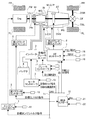
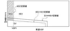
- FIG. 1 is an overall system diagram illustrating an FR hybrid vehicle (an example of a vehicle) by rear wheel drive to which an automatic transmission control device according to a first embodiment is applied. It is a figure which shows an example of the EV-HEV selection map set to the mode selection part of the integrated controller of Example 1.
- FIG. 3 is a skeleton diagram illustrating an example of an automatic transmission including a frictional engagement element that is a target of stroke learning control in the automatic transmission control device according to the first embodiment. 3 is an engagement operation table showing an engagement state of each friction engagement element for each shift stage in the automatic transmission according to the first embodiment. It is a figure which shows an example of the shift map of the automatic transmission set to the AT controller in Example 1.
- FIG. 3 is a skeleton diagram illustrating an example of an automatic transmission including a frictional engagement element that is a target of stroke learning control in the automatic transmission control device according to the first embodiment.
- 3 is an engagement operation table showing an engagement state of each friction engagement element for each shift stage in the automatic transmission according to the first embodiment
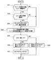
- FIG. 4 is a flowchart showing a flow of N ⁇ D select control processing executed by an AT controller in Embodiment 1.
- 6 is a flowchart illustrating a flow of a prohibition flag setting process executed by an AT controller according to the first embodiment.
- 10 is a flowchart illustrating a flow of a prohibition flag setting process executed by an AT controller according to the second embodiment.
- 12 is a flowchart illustrating a flow of a prohibition flag setting process executed by an AT controller according to a third embodiment.
- control device for the automatic transmission in the first embodiment is divided into “overall system configuration”, “detailed configuration of automatic transmission”, “detailed configuration of N ⁇ D select control process”, and “detailed configuration of prohibition flag setting process”. I will explain.
- FIG. 1 shows a rear-wheel drive FR hybrid vehicle to which the automatic transmission control device according to the first embodiment is applied
- FIG. 2 shows an EV-HEV selection map set in a mode selection unit of the integrated controller 10. An example is shown.
- the overall system configuration will be described below with reference to FIGS.
- the drive system of the FR hybrid vehicle includes an engine Eng, a first clutch CL1, a motor / generator MG (motor), a second clutch CL2, an automatic transmission AT, and a transmission input shaft. It has IN, propeller shaft PS, differential DF, left drive shaft DSL, right drive shaft DSR, left rear wheel RL (drive wheel), and right rear wheel RR (drive wheel).
- M-O / P is a mechanical oil pump
- S-O / P is an electric oil pump
- FL is a left front wheel
- FR is a right front wheel
- FW is a flywheel.
- the first clutch CL1 is a fastening element provided between the engine Eng and the generator MG, and is engaged by an urging force of a diaphragm spring or the like when the CL1 hydraulic pressure is not applied, and counteracts this urging force.
- This type is a so-called normally closed clutch that is released by applying CL1 hydraulic pressure.
- the automatic transmission AT is a stepped transmission that automatically switches the shift speed between the seventh forward speed and the first reverse speed according to the vehicle speed, the accelerator opening, and the like.
- the second clutch CL2 interposed between the motor / generator MG and the left and right rear wheels RL, RR is not a newly added dedicated clutch independent of the automatic transmission AT, but the automatic transmission AT. Friction engagement elements (clutch and brake) for shifting are used. That is, the second clutch CL2 is a frictional engagement element selected as an element suitable for the engagement condition among a plurality of frictional engagement elements that are engaged at each gear stage of the automatic transmission AT.
- the first clutch hydraulic unit 6 and the second clutch hydraulic unit 8 are built in an AT hydraulic control valve unit CVU attached to the automatic transmission AT.
- EV mode electric vehicle mode
- HEV mode hybrid vehicle mode
- EV mode drive torque control mode
- WSC mode drive torque control mode
- the “EV mode” is a mode in which the first clutch CL1 is disengaged and the drive source is only the motor / generator MG, and includes a motor drive mode (motor power running) and a generator power generation mode (generator regeneration). This “EV mode” is selected, for example, when the required driving force is low and the battery SOC is secured.
- the “HEV mode” is a mode in which the first clutch CL1 is engaged and the drive source is the engine Eng and the motor / generator MG.
- the motor assist mode (motor power running), engine power generation mode (generator regeneration), and deceleration regeneration It has a power generation mode (generator regeneration).
- This “HEV mode” is selected, for example, when the required driving force is high or when the battery SOC is insufficient.
- the “WSC mode” is driven in the “HEV mode”, but the torque transmission of the second clutch CL2 is maintained while maintaining the second clutch CL2 in the slip engagement state by controlling the rotation speed of the motor / generator MG. This mode controls the capacity.
- the torque transmission capacity of the second clutch CL2 is controlled so that the driving force transmitted after passing through the second clutch CL2 becomes the required driving force that appears in the accelerator operation amount of the driver.
- the “WSC mode” is selected in a region where the engine speed is lower than the idle speed, such as when starting in the “HEV mode” selection state.
- the control system of the FR hybrid vehicle includes an engine controller 1, a motor controller 2, an inverter 3, a battery 4, a first clutch controller 5, a first clutch hydraulic unit 6, and an AT controller. 7, a second clutch hydraulic unit 8, a brake controller 9, and an integrated controller 10.
- the controllers 1, 2, 5, 7, 9 and the integrated controller 10 are connected via a CAN communication line 11 that can exchange information with each other.
- 12 is an engine speed sensor
- 13 is a resolver
- 15 is a first clutch stroke sensor that detects the stroke position of the piston 14a of the hydraulic actuator 14
- 19 is a wheel speed sensor
- 20 is a brake stroke sensor.
- the AT controller 7 inputs information from an accelerator opening sensor 16, a vehicle speed sensor 17, an inhibitor switch 18 for detecting a selected range position (N range, D range, R range, P range, etc.), and the like. . Then, when driving with the D range selected, the optimum shift stage is searched based on the position where the driving point determined by the accelerator opening APO and the vehicle speed VSP exists on the shift map (see FIG. 5), and the searched shift The control command to obtain the gear is output to the AT hydraulic control valve unit CVU. In addition to this shift control, engagement / slip / release control of the first clutch CL1 and the second clutch CL2 is performed based on a command from the integrated controller 10.
- the integrated controller 10 manages the energy consumption of the entire vehicle and has a function for running the vehicle with the highest efficiency.
- the motor rotation number sensor 21 for detecting the motor rotation number Nm and other sensors and switches 22 Necessary information and information via the CAN communication line 11 are input.
- the integrated controller 10 includes a mode selection unit that selects a mode in which an operating point determined by the accelerator opening APO and the vehicle speed VSP is searched based on a position on the EV-HEV selection map shown in FIG. 2 as a target mode. Then, engine start control is performed when the mode is switched from the “EV mode” to the “HEV mode”. In addition, engine stop control is performed when the mode is switched from the “HEV mode” to the “EV mode”. In this engine stop control, a CL1 release process by applying CL1 hydraulic pressure to the first clutch CL1 engaged in the “HEV mode”, an engine stop process for stopping the engine Eng disconnected by the release of the first clutch CL1, Is done.
- FIG. 3 shows an example of the automatic transmission AT according to the first embodiment in a skeleton diagram
- FIG. 4 shows the engagement state of each friction engagement element for each shift stage in the automatic transmission AT
- FIG. 5 shows the AT controller
- 7 shows an example of a shift map of the automatic transmission AT set to 7. The detailed configuration of the automatic transmission AT will be described below with reference to FIGS.
- the automatic transmission AT is a stepped automatic transmission with 7 forward speeds and 1 reverse speed. As shown in FIG. 3, the driving force from at least one of the engine Eng and the motor / generator MG is input to the transmission. The rotational speed is changed by a transmission gear mechanism having four planetary gears and seven frictional engagement elements, which is input from the shaft Input, and is output from the transmission output shaft Output.
- a first planetary gear set GS1 composed of a first planetary gear G1 and a second planetary gear G2 and a second planetary gearset GS2 composed of a third planetary gear G3 and a fourth planetary gear G4 are coaxially arranged.
- the first clutch C1, the second clutch C2, the third clutch C3, the first brake B1, the second brake B2, the third brake B3, and the fourth brake B4 are used as hydraulically operated frictional engagement elements.
- a first one-way clutch F1 and a second one-way clutch F2 are arranged as engagement elements for machine operation.
- the first planetary gear G1, the second planetary gear G2, the third planetary gear G3, and the fourth planetary gear G4 include a sun gear (S1 to S4), a ring gear (R1 to R4), and both gears (S1 to S4), And a carrier (PC1 to PC4) for supporting pinions (P1 to P4) meshing with (R1 to R4).
- the transmission input shaft Input is connected to the second ring gear R2 and inputs rotational driving force from at least one of the engine Eng and the motor generator MG.
- the transmission output shaft Output is coupled to the third carrier PC3, and transmits the output rotational driving force to the driving wheels (left and right rear wheels RL, RR) via a final gear or the like.
- the first ring gear R1, the second carrier PC2, and the fourth ring gear R4 are integrally connected by the first connecting member M1.
- the third ring gear R3 and the fourth carrier PC4 are integrally connected by the second connecting member M2.
- the first sun gear S1 and the second sun gear S2 are integrally connected by a third connecting member M3.
- FIG. 4 is a fastening operation table.
- ⁇ indicates that the friction engagement element is hydraulically engaged in the drive state
- ( ⁇ ) indicates that the friction engagement element is hydraulically engaged (drive state) in the coast state.
- no mark indicates that the frictional engagement element is in a released state.
- the second brake B2 (the friction engagement element that is engaged in the travel range) is performed when an N ⁇ D selection operation is performed to switch from the neutral range (N range) to the drive range (D range) that is the travel range.
- N range neutral range
- D range drive range
- the “backlash control” is a control in which the initial hydraulic pressure is applied so as to eliminate the gap between the brake plates of the second brake B2. This backlash control is performed in order to ensure start response by immediately setting the second brake B2 to the hydraulically engaged state at the time of start by the accelerator depression operation.
- “first gear” is obtained by engaging the second brake B2 and engaging the first one-way clutch F1 and the second one-way clutch F2, and the second brake B2 is set to the second brake B2.
- the clutch is CL2.
- FIG. 5 is a shift map.
- an upshift command is output.
- the shift speed is the first speed
- the driving point (VSP, APO) crosses the 1 ⁇ 2 up shift line due to the increase in the vehicle speed VSP
- a 1 ⁇ 2 up shift command is output.
- FIG. 5 shows only the up shift line, but of course, the down shift line is also set with hysteresis for the up shift line.
- FIG. 6 is a flowchart showing the flow of the N ⁇ D select control process executed by the AT controller 7 in the first embodiment. In the following, each step of FIG. 6 showing the detailed configuration of the N ⁇ D select control process will be described.
- step S1 it is determined whether or not N ⁇ D select control is started, which is started when the signal from the inhibitor switch 18 changes from the N range signal to the D range signal. If YES (N ⁇ D select control is in progress), the process proceeds to step S2. If NO (N ⁇ D select control is not in progress), the process proceeds to return.
- the “prohibition flag” is determined that the piston stroke is completed and the engagement of the second brake B2 is started when the condition of MG torque change> threshold is satisfied when N ⁇ D is selected in the HEV mode.
- N ⁇ D select normal control means that when N ⁇ D is selected, backlash control of the second brake B2 is performed by the command hydraulic pressure rewritten and stored by learning control.
- step S4 following the N ⁇ D select normal control in step S3, stroke learning control for learning the command hydraulic pressure of the second brake B2 is permitted, and the process proceeds to return (engagement start determination means).
- the “stroke learning control” is control for learning the command hydraulic pressure of the second brake B2 so that the backlash control time from the start of N ⁇ D selection to the completion of the piston stroke becomes the target time. That is, the required time from the start of N ⁇ D selection to the completion of the piston stroke is measured, and if the required time exceeds the target time, the indicated hydraulic pressure is increased by a predetermined learning amount. Conversely, if it is less than the target time, the command oil pressure is lowered by a predetermined learning amount.
- step S6 following the N ⁇ D select OPEN control in step S5, the stroke learning control for learning the indicated hydraulic pressure during the looseness control of the second brake B2 is prohibited, and the process proceeds to return (determination prohibiting means).
- the completion of the backlash control is determined by the elapse of the backlash timer time.
- FIG. 7 is a flowchart illustrating the flow of the prohibition flag setting process executed by the AT controller 7 according to the first embodiment. Hereinafter, each step of FIG. 7 showing a detailed configuration of the prohibition flag setting process will be described.
- the “threshold value” is set to an instruction hydraulic pressure value that gives an equivalent hydraulic pressure to release the normally closed first clutch CL1.
- the “predetermined value” is set based on the time required until it is determined that the engine Eng is not completely exploded in the engine stop control performed in association with the mode switching from the HEV mode to the EV mode.
- step S14 following the determination that CL1 command hydraulic pressure previous value ⁇ 0 in step S11, or the CL1 command hydraulic pressure ⁇ threshold value in step S12, or the countdown timer set in step S13, The CL1 instruction hydraulic pressure previous value is updated, and the process proceeds to step S15.
- the previous CL1 command oil pressure is It is updated by setting the previous CL1 command oil pressure value to the current CL1 command oil pressure value.
- step S16 following the determination that the timer value> 0 in step S15, the prohibition flag representing prohibition of the fastening start determination is set to 1, and the process proceeds to step S17.
- the “prohibition flag” is used in step S2 of FIG. 6, and when the N ⁇ D selection in the HEV mode is selected, the piston stroke is completed when the condition of MG torque change> threshold is satisfied, A flag that prohibits the engagement start determination that determines that the engagement of the second brake B2 has started.
- step S17 following the prohibition flag setting in step S16, a timer countdown is performed to decrease the timer value at that time every processing cycle, and the process proceeds to return.
- control device for the automatic transmission AT is divided into [N ⁇ D select control processing operation], [prohibition flag setting processing operation], and [mode transition intervention operation during N ⁇ D select control]. To do.
- N ⁇ D select control processing action During the N ⁇ D select control for engaging the second brake B2, when the control for switching from the HEV mode to the EV mode intervenes and both controls are executed so as to overlap each other, the engagement start determination is erroneously determined. It is necessary to prohibit the fastening start determination under the conditions. In the following, the N ⁇ D select control processing operation that reflects this will be described.
- step S3 at the time of N ⁇ D selection, N ⁇ D selection normal control for performing looseness control of the second brake B2 by the command hydraulic pressure rewritten and stored by learning control is performed.
- step S4 stroke learning control for learning the command hydraulic pressure of the second brake B2 is permitted.
- step S6 the stroke learning control for learning the command oil pressure during the backlash control of the second brake B2 is prohibited.
- the MG torque change amount> the threshold value the configuration that prohibits the determination of fastening start when the condition is established is adopted.
- the rotational speed of the motor / generator MG is controlled so that the input rotational speed of the automatic transmission AT is constant.
- the load applied to the motor / generator MG increases.
- the torque of the motor / generator MG is increased. Increase to maintain speed control. Therefore, when the load of the motor / generator MG increases by a predetermined amount and the condition that MG torque change amount> threshold value is satisfied, it can be determined that the piston stroke is completed and the second brake B2 has started engagement.
- the process proceeds to step S5, and the command hydraulic pressure of the second brake B2 is set higher than the case where it is not prohibited for a predetermined period by the backlash timer.
- the backlash control of the second brake B2 is performed in a time shorter than the target time in the N ⁇ D select normal control. Will be completed. Therefore, even when it is not possible to determine the engagement start of the second brake B2 from the load fluctuation amount of the motor / generator MG, the engagement of the second brake B2 has started (the backlash of the second brake B2 is completed). Can be guaranteed).
- step S11 ⁇ step S12 ⁇ step in the flowchart of FIG.
- the process proceeds from S13, step S14, step S15, step S16, step S17, and return.
- a prohibition flag 1 for prohibiting the engagement start determination is set.
- FIG. 8 is a time chart showing characteristics when switching from the HEV mode to the EV mode intervenes during the N ⁇ D select control while the hybrid vehicle equipped with the control device of the first embodiment is stopped.
- the mode transition intervention action during N ⁇ D select control will be described below with reference to FIG.
- t1 is the N ⁇ D select control start time according to the pattern (1) in the HEV mode.
- t2 is the engine stop start and CL1 release start time based on the mode transition command from the HEV mode to the EV mode.
- t3 is the zero transition completion time of the engine torque and the motor torque.
- t4 is the rotation zero shift start time of the engine speed and the motor speed.
- t5 is the rotation zero transition completion time and the EV mode start time.
- an engine power generation phase in the HEV mode For example, when a condition such as completion of charging of the battery 4 is satisfied at time t2, a phase transition signal from the HEV mode to the EV mode is output. In this phase, the rotational speed of the motor / generator MG is controlled so that the idle rotational speed is maintained with the idle rotational speed of the engine Eng as the target rotational speed.
- the engine torque is controlled to a torque that provides a necessary power generation amount, and the motor torque is controlled to a negative torque (regenerative torque) that converts the engine torque into generated energy.
- the CL1 command torque and the CL1 actual torque are torques that keep the first clutch CL1 engaged.
- the CL1 command hydraulic pressure is maintained at zero pressure, and the first clutch CL1 is in the engaged state, so both the timer and the prohibition flag are set to zero.
- the engine power generation phase in the HEV mode from time t1 to time t2 is a period for normal control and learning permission.
- From time t2 to time t3 is the HEV ⁇ EV transition (1) phase, when engine stop processing and first clutch release processing are started at time t2, and when zero transition of engine torque and motor torque is completed at time t3 Move on to the next phase.
- the rotational speed control of the motor / generator MG is maintained so as to maintain the idle rotational speed with the idle rotational speed of the engine Eng as the target rotational speed.
- the engine torque is controlled so that the torque is gradually decreased by the throttle closing control, and the motor torque is gradually increased in accordance with the engine torque.
- the CL1 command hydraulic pressure increases stepwise at time t2, and then gradually increases toward time t3.
- the timer is set to a predetermined value when the threshold is exceeded due to the rise of the CL1 command oil pressure, and gradually decreases toward time t3.
- the prohibition flag is set to 1 when the timer value> 0.
- the HEV ⁇ EV transition (1) phase from time t2 to time t3 is a period during which OPEN control and learning are prohibited.
- the CL1 command torque and the CL1 actual torque are controlled so that the response of the CL1 actual torque is delayed with respect to the CL1 command torque, but the CL1 command torque becomes zero at time t4.
- the CL1 indicated hydraulic pressure maintains the hydraulic pressure at time t3.
- the timer becomes zero at a timing slightly exceeding time t3.
- the prohibition flag based on the timer is reset when the timer becomes zero, but in Example 1, the engine Eng has not completely exploded at time t3 (the flag indicating that the complete explosion has disappeared)
- the CL1 command torque and the CL1 actual torque are maintained at zero indicating the released state of the first clutch CL1.
- the CL1 indicated hydraulic pressure maintains the hydraulic pressure at time t4.
- the prohibition flag is kept standing based on the information that the engine Eng has not completely exploded. And after time t5, it prepares for the start by accelerator operation in EV mode. In the EV mode after time t5, because the vehicle is stopped, the rotation speed is zero, and the stroke determination based on the MG torque change amount cannot be made (the rotation does not change even when the clutch is engaged). "Is set.
- ⁇ pattern 1 In the pattern (1) where the timing of the backlash filling to the backlash completion timing is before the OPEN control (learning prohibited), the backlash filling starts at the time t1, and the backlash filling is completed before the time t2, that is, the HEV Backlash control is completed during the mode. Therefore, N ⁇ D select normal control and stroke learning control are permitted, and completion of backlashing (engagement start determination) is confirmed by satisfying the condition that MG torque change amount> threshold, as indicated by arrow A in FIG.
- Pattern (2) In pattern (2) where the backlash start timing is before OPEN control (learning prohibited) but the backlash completion timing is after OPEN control (learning prohibited), the backlash start timing before time t2, The backlashing is completed after time t2, that is, the mode switching control and backlash control partially overlap. For this reason, if the backlash completion determination (engagement start determination) is performed when the condition that MG torque change amount> threshold value is satisfied, there is a possibility of erroneous determination. While changing to the select OPEN control, the stroke learning control is prohibited. Therefore, the erroneous determination of the fastening start determination can be prevented. Note that the determination of completion of backlashing is performed when the backlash timer time TG elapses, and the hatched area shown in FIG. 8B indicates a portion where the pressure is higher than the command oil pressure in normal control.
- Pattern (3) In pattern (3) where the timing to start backlash is after OPEN control (learning prohibited), start backlashing after time t2 and complete backlashing after time t3, that is, mode switching control and backlash control. Overlap each other. For this reason, if the backlash completion determination (engagement start determination) is performed when the condition that MG torque change amount> threshold value is satisfied, there is a possibility of erroneous determination. While changing to the select OPEN control, the stroke learning control is prohibited. Therefore, the erroneous determination of the fastening start determination can be prevented.
- the determination of completion of backlashing is performed when the backlash timer time TG elapses, and the hatched area shown in FIG. 8C indicates a portion where the pressure is higher than the command oil pressure in normal control.
- the friction engagement element that is in the released state when the rotation range is selected (N ⁇ D selection) during rotation speed control for controlling the rotation speed of the input shaft IN of the automatic transmission AT to a predetermined target rotation speed Engagement start determination for determining that the frictional engagement element (second brake B2) has started engagement when the load of the motor (motor / generator MG) increases by a predetermined amount when engaging (second brake B2).
- the driving force of the engine Eng and the motor (motor / generator MG) is input to the input shaft IN before it is determined that the friction engagement element (second brake B2) has started engagement.
- the determination prohibiting means for prohibiting the determination by the fastening start determining means (FIG. 6 steps S2 ⁇ S5 ⁇ S6), Is provided. For this reason, it is possible to prevent erroneous determination of the load variation of the motor (motor / generator MG) caused by switching from the HEV mode to the EV mode as the engagement start of the friction engagement element (second brake B2).
- step S2 When the determination is prohibited by the determination prohibiting means (steps S2 ⁇ S5 ⁇ S6 in FIG. 6), the command hydraulic pressure to the frictional engagement element (second brake B2) is set for a predetermined period (offset). Timer time TG), and a prohibition-time hydraulic pressure setting means (step S5 in FIG. 6) for setting an instruction hydraulic pressure higher than that when not prohibited. For this reason, in addition to the effect of (1), even if it is not possible to determine the engagement start of the friction engagement element (second brake B2) from the load fluctuation amount of the motor / generator MG, the friction engagement element (second brake B2) It is possible to ensure that the backlash has been completed.
- step S2 The determination prohibiting means (step S2, FIG. 7 in FIG. 6) is before it is determined that the friction engagement element (second brake B2) has started engagement, and the engine Eng and the engine
- the determination by the engagement start determination means is prohibited (step S16 in FIG. 7).
- the engagement start determination is prohibited, thereby switching from the HEV mode to the EV mode. It is possible to prevent erroneous determination that the fluctuation of the generated load of the motor / generator MG is the start of fastening.
- Example 2 is an example in which the engagement start determination based on the MG torque change amount is prohibited when a phase transition signal from the HEV mode to the EV mode is detected.
- FIG. 9 is a flowchart illustrating the flow of the prohibition flag setting process executed by the AT controller 7 according to the second embodiment. Hereinafter, each step of FIG. 9 showing the detailed configuration of the prohibition flag setting process will be described. Steps S23 and S25 to S28 correspond to steps S13 and S15 to S18 in FIG. 7 and will not be described.
- step S24 following the determination that the phase signal previous value ⁇ HEV mode phase in step S21, or the determination that the phase is not the HEV ⁇ EV transition phase in step S22, or the countdown timer set in step S23, The previous value of the phase signal is updated, and the process proceeds to step S25.
- step S21 ⁇ step S22 ⁇ step S23 ⁇ step S24 ⁇ step S25 ⁇ step S26 ⁇ step S27 ⁇ return Proceed to
- step S26 following the determination that the timer value> 0 in step S25, a prohibition flag representing prohibition of fastening start determination is set to “1”. Is done.
- a prohibition flag for prohibiting the engagement start determination A configuration for setting 1 was adopted. That is, switching from the HEV mode to the EV mode occurs based on the phase transition signal from the HEV mode to the EV mode. For this reason, by prohibiting the engagement start determination when a phase transition signal from the HEV mode to the EV mode is detected, the change in the load on the motor / generator MG caused by switching from the HEV mode to the EV mode is started. Can be prevented from being erroneously determined. Since other operations are the same as those of the first embodiment, description thereof is omitted.
- the determination prohibiting means (steps S2, FIG. 9 in FIG. 6) is before it is determined that the friction engagement element (second brake B2) has started engagement, and from the HEV mode.
- the determination by the engagement start determining means is prohibited (step S26 in FIG. 9).
- the fastening start determination is prohibited, thereby switching from the HEV mode to the EV mode. It can be prevented that a change in the load on the motor / generator MG caused by the switching is erroneously determined as the start of fastening. That is, based on the phase transition signal from the HEV mode to the EV mode, focusing on the point at which switching from the HEV mode to the EV mode occurs, the fastening start determination based on the MG torque change amount is prohibited.
- Example 3 is an example in which the fastening start determination based on the MG torque change amount is prohibited when it is detected that the engine stop process has started.
- FIG. 10 is a flowchart illustrating the flow of the prohibition flag setting process executed by the AT controller 7 according to the third embodiment. Hereinafter, each step of FIG. 10 showing the detailed configuration of the prohibition flag setting process will be described.
- the steps S33 and S35 to S38 correspond to the steps S13 and S15 to S18 in FIG.
- step S34 it is determined in step S31 that the previous value of the engine state is not equal to the engine being driven, or in step S32, it is determined that the engine stop process start signal is not detected, or the countdown timer set in step S33 is set. Subsequently, the previous engine state value is updated, and the process proceeds to step S35.
- step S31 ⁇ step S32 ⁇ step S33 ⁇ It progresses to step S34-> step S35-> step S36-> step S37-> return.
- the determination prohibiting means (steps S2 and FIG. 10 in FIG. 6) is before it is determined that the friction engagement element (second brake B2) has started engagement, and the engine Eng is stopped.
- the determination by the fastening start determination unit is prohibited (step S36 in FIG. 10).
- the HEV mode is changed to the EV mode. It can be prevented that a change in the load on the motor / generator MG caused by the switching is erroneously determined as the start of fastening. That is, at the time of switching from the HEV mode to the EV mode, the engagement start determination based on the MG torque change amount is prohibited by paying attention to the point that the engine Eng stop process is started.
- control device for an automatic transmission has been described based on the first to third embodiments.
- specific configuration is not limited to these embodiments, and each of the claims Design changes and additions are permitted without departing from the scope of the claimed invention.
- the determination prohibition unit an example in which the prohibition flag is set based on the command hydraulic pressure to the first clutch CL1 is shown.
- the determination prohibiting means the actual hydraulic pressure of the first clutch CL1 may be detected, and the setting of the prohibition flag may be determined based on the CL1 actual hydraulic pressure.
- the determination prohibiting unit may detect that the engine stop process has started when it is detected that the engine torque has decreased.
- the fastening element provided between the engine and the motor may be an example in which a normally open first clutch that is released by releasing the hydraulic pressure is used.
- Examples 1 to 3 are applied to a hybrid vehicle equipped with an electric oil pump SO / P, and the mechanical oil pump MO / P driven by the input shaft of the automatic transmission AT is not driven while the vehicle is stopped in the EV mode. Indicated.
- the present invention is not limited to this.
- the vehicle does not include an electric oil pump, and the motor rotates the input shaft at a constant speed to drive the mechanical oil pump even when the vehicle is stopped in the EV mode. It can also be applied when shifting from the HEV mode to the EV mode in a vehicle that maintains the number.
- the timer for the prohibition flag is set to be sufficiently long with respect to the time from the start of engine stop processing until the complete explosion flag disappears (HEV ⁇ EV transition (1) phase).
- the timer for the prohibition flag may be set to a timer length that prohibits the stroke determination and stroke learning control based on the MG torque change amount until the EV mode is completely changed from the HEV mode.
- control device for an automatic transmission according to the present invention is applied to an FR hybrid vehicle having one motor and two clutches.
- the control device for an automatic transmission according to the present invention is not limited to a FF hybrid vehicle having one motor and two clutches, but also for types other than the one motor and two clutches, for example, a parallel type hybrid vehicle having a power split mechanism. Can also be applied.
- the present invention can be applied to any electric vehicle including an automatic transmission to which a driving force from a driving source including an engine and a motor is input.
Abstract
Description
前記締結開始判定手段は、前記自動変速機の入力軸の回転数を所定の目標回転数に制御する回転数制御中であって、かつ前記走行レンジが選択されて解放状態の前記摩擦締結要素を締結する際に、前記モータの負荷が所定量増加した場合、前記摩擦締結要素が締結を開始したと判定する。
前記判定禁止手段は、前記摩擦締結要素が締結を開始したと判定される前であって、かつ、前記入力軸に前記エンジンおよび前記モータの駆動力が入力されるHEVモードから、前記入力軸にモータ単独の駆動力が入力されるEVモードへの切り換えが生じた場合は、前記締結開始判定手段による判定を禁止する。
すなわち、締結開始判定手段では、変速機入力軸の回転数制御中であって、かつ走行レンジが選択されて解放状態の摩擦締結要素を締結する際に、モータの負荷が所定量増加した場合、摩擦締結要素が締結を開始したと判定する。しかし、HEVモードからEVモードへの切り換えが生じると、エンジン停止処理やエンジンとモータとの切り離し処理が行われることでモータの負荷が変動する。このように、走行レンジが選択されて摩擦締結要素が締結される際、HEVモードからEVモードへの切り換えが介入した場合、エンジン停止処理等により生じるモータの負荷変動を、摩擦締結要素の締結開始による負荷変動と誤判定してしまう。このため、HEVモードからEVモードへの切り換えが生じたときは、モータの負荷変動による摩擦締結要素の締結開始判定を行わない。
この結果、HEVモードからEVモードへの切り換えに伴って生じるモータの負荷変動を、摩擦締結要素の締結開始と誤判定するのを防止することができる。
実施例1における自動変速機の制御装置を、「全体システム構成」、「自動変速機の詳細構成」、「N→Dセレクト制御処理の詳細構成」、「禁止フラグ設定処理の詳細構成」に分けて説明する。
図1は、実施例1における自動変速機の制御装置が適用された後輪駆動によるFRハイブリッド車両を示し、図2は、統合コントローラ10のモード選択部に設定されているEV-HEV選択マップの一例を示す。以下、図1及び図2に基づいて、全体システム構成を説明する。
図3は、実施例1における自動変速機ATの一例をスケルトン図により示し、図4は、自動変速機ATでの変速段ごとの各摩擦締結要素の締結状態を示し、図5は、ATコントローラ7に設定されている自動変速機ATのシフトマップの一例を示す。以下、図3~図5に基づいて、自動変速機ATの詳細構成を説明する。
図6は、実施例1におけるATコントローラ7にて実行されるN→Dセレクト制御処理の流れを示すフローチャートである。以下、N→Dセレクト制御処理の詳細構成をあらわす図6の各ステップについて説明する。
ここで、「禁止フラグ」とは、HEVモードでのN→Dセレクト時、MGトルク変化量>閾値という条件が成立したときにピストンストロークが完了し、第2ブレーキB2の締結が開始されたと判定する締結開始判定を禁止するフラグをいう。すなわち、MGトルク変化量>閾値という条件成立により行われるストローク完了判定を、第2ブレーキB2を介して駆動トルクの伝達を開始する第2ブレーキB2の締結開始判定とする。
ここで、「N→Dセレクト通常制御」とは、N→Dセレクト時、学習制御により書き換え保存されている指示油圧により第2ブレーキB2のガタ詰め制御を行うことをいう。
ここで、「ストローク学習制御」とは、N→Dセレクト開始からピストンストローク完了までのガタ詰め制御時間が目標時間となるように、第2ブレーキB2の指示油圧を学習する制御である。すなわち、N→Dセレクト開始からピストンストローク完了までの所要時間を計測し、所要時間が目標時間を超えている場合は、指示油圧を所定の学習量だけ高くする。逆に、目標時間未満の場合は、指示油圧を所定の学習量だけ低くする。この学習補正を多数回経験することで、N→Dセレクト開始からピストンストローク完了までの所要時間を、バラツキや経時劣化等にかかわらず目標時間に収束させる制御である。また、「ストローク学習制御の許可」とは、HEVモードでのN→Dセレクト時、MGトルク変化量>閾値という条件が成立したときにピストンストローク完了(=締結開始)と判定し、N→Dセレクト開始からピストンストローク完了までの所要時間を計測する。そして、所要時間が目標時間より長いか短いかによりガタ詰め制御中の指示油圧を補正する学習制御を許可することをいう。
ここで、「N→DセレクトOPEN制御」とは、ストローク学習制御を禁止する禁止フラグ=1の場合に、第2ブレーキB2(=CL2)のガタ詰めを行う指示油圧を、ガタ詰めタイマーによる所定期間の間、禁止されていない通常時の指示油圧(学習油圧)よりも高圧の指示圧とする制御(OPEN制御)をいう。
ここで、「ストローク学習制御の禁止」とは、HEVモードでのN→Dセレクト時にMGトルク変化量>閾値という条件が成立したときにピストンストローク完了(=締結開始)と判定することを禁止し、ストローク学習制御を行わないことをいう。なお、ストローク学習制御が禁止されたとき、ガタ詰め制御の完了は、ガタ詰めタイマー時間の経過により判断する。
図7は、実施例1におけるATコントローラ7にて実行される禁止フラグ設定処理の流れを示すフローチャートである。以下、禁止フラグ設定処理の詳細構成をあらわす図7の各ステップについて説明する。
ここで、「閾値」は、ノーマルクローズの第1クラッチCL1を解放する油圧相当を与える指示油圧値に設定される。
ここで、「所定値」は、HEVモードからEVモードへのモード切り換えに伴って行われるエンジン停止制御のうち、エンジンEngが完爆していないと判断されるまでに要する時間に基づいて設定される。
ここで、CL1指示油圧前回値は、
CL1指示油圧前回値=CL1指示油圧今回値
とすることで更新される。
ここで、「禁止フラグ」とは、図6のステップS2で用いられるもので、HEVモードでのN→Dセレクト時、MGトルク変化量>閾値という条件が成立したときにピストンストロークが完了し、第2ブレーキB2の締結が開始されたと判定する締結開始判定を禁止するフラグをいう。
実施例1の自動変速機ATの制御装置における作用を、[N→Dセレクト制御処理作用]、[禁止フラグ設定処理作用]、[N→Dセレクト制御中におけるモード移行介入作用]に分けて説明する。
第2ブレーキB2を締結するN→Dセレクト制御中に、HEVモードからEVモードへの切り換え制御が介入し、両制御が互いに重なり合うように実行されると、締結開始判定を誤判定するため、一定の条件下で締結開始判定を禁止する必要がある。以下、これを反映するN→Dセレクト制御処理作用を説明する。
この構成により、第2ブレーキB2の締結開始判断が禁止されている場合(禁止フラグ=1)、第2ブレーキB2のガタ詰め制御が、N→Dセレクト通常制御での目標時間より短い時間にて完了することになる。
したがって、モータ/ジェネレータMGの負荷変動量から第2ブレーキB2の締結開始を判断できない場合であっても、第2ブレーキB2の締結が開始している状態(第2ブレーキB2のガタ詰めが完了している状態)を保障することができる。
上記のように、HEVモードからEVモードへの切り換えが生じたとき、モード切り換えであることを示す具体的な条件により禁止フラグを1にセットする。以下、モード切り換えであることを示す具体的な条件として、第1クラッチCL1の解放条件を用いた実施例1の禁止フラグ設定処理作用を説明する。
すなわち、HEVモードからEVモードへの切り換えるときには、エンジンEngとモータ/ジェネレータMGとの間に設けられた第1クラッチCL1を解放するクラッチ解放制御が開始される。このため、第1クラッチCL1が解放を開始したときに締結開始判定を禁止することによって、HEVモードからEVモードへの切り換えに伴って生じるモータ/ジェネレータMGの負荷の変動を締結開始と誤判定することを防止することができる。
図8は、実施例1の制御装置を搭載したハイブリッド車両が停車状態においてN→Dセレクト制御中にHEVモードからEVモードへの切り換えが介入した場合における各特性を示すタイムチャートである。以下、図8に基づき、N→Dセレクト制御中におけるモード移行介入作用を説明する。
ガタ詰め開始~ガタ詰め完了のタイミングがOPEN制御(学習禁止)の前であるパターン(1)では、時刻t1にてガタ詰めを開始し、時刻t2になる前にガタ詰めを完了、すなわち、HEVモード中にガタ詰め制御が完了する。このため、N→Dセレクト通常制御とストローク学習制御が許可され、ガタ詰め完了(締結開始判定)を、図8の矢印Aに示すように、MGトルク変化量>閾値という条件成立により確認する。
ガタ詰め開始タイミングがOPEN制御(学習禁止)の前であるが、ガタ詰め完了タイミングがOPEN制御(学習禁止)の後であるパターン(2)では、時刻t2の前にてガタ詰めを開始し、時刻t2の後にガタ詰めを完了、すなわち、モード切り換え制御とガタ詰め制御が部分的に重なり合う。このため、ガタ詰め完了判定(締結開始判定)を、MGトルク変化量>閾値という条件成立により行うと誤判定の可能性があることで、時刻t2にてN→Dセレクト通常制御からN→DセレクトOPEN制御に変更されるとともに、ストローク学習制御が禁止される。よって、締結開始判定の誤判定を防止できる。なお、ガタ詰め完了の判定は、ガタ詰めタイマー時間TGの経過により行うもので、図8のBに示すハッチング領域が、通常制御での指示油圧より高圧とした部分を示す。
ガタ詰め開始タイミングがOPEN制御(学習禁止)の後であるパターン(3)では、時刻t2の後にてガタ詰めを開始し、時刻t3の後にガタ詰めを完了、すなわち、モード切り換え制御とガタ詰め制御が互いに重なり合う。このため、ガタ詰め完了判定(締結開始判定)を、MGトルク変化量>閾値という条件成立により行うと誤判定の可能性があることで、時刻t2にてN→Dセレクト通常制御からN→DセレクトOPEN制御に変更されるとともに、ストローク学習制御が禁止される。よって、締結開始判定の誤判定を防止できる。なお、ガタ詰め完了の判定は、ガタ詰めタイマー時間TGの経過により行うもので、図8のCに示すハッチング領域が、通常制御での指示油圧より高圧とした部分を示す。
実施例1の自動変速機ATの制御装置にあっては、下記に列挙する効果を得ることができる。
走行レンジ(Dレンジ)で締結される摩擦締結要素(第2ブレーキB2)と、
前記自動変速機ATの入力軸INの回転数を所定の目標回転数に制御する回転数制御中であって、かつ前記走行レンジが選択(N→Dセレクト)されて解放状態の前記摩擦締結要素(第2ブレーキB2)を締結する際に、前記モータ(モータ/ジェネレータMG)の負荷が所定量増加した場合、前記摩擦締結要素(第2ブレーキB2)が締結を開始したと判定する締結開始判定手段(図6のステップS2→S3→S4)と、
前記摩擦締結要素(第2ブレーキB2)が締結を開始したと判定される前であって、かつ、前記入力軸INに前記エンジンEngおよび前記モータ(モータ/ジェネレータMG)の駆動力が入力されるHEVモードから、前記入力軸INにモータ(モータ/ジェネレータMG)単独の駆動力が入力されるEVモードへの切り換えが生じた場合は、前記締結開始判定手段による判定を禁止する判定禁止手段(図6のステップS2→S5→S6)と、
を備える。
このため、HEVモードからEVモードへの切り換えに伴って生じるモータ(モータ/ジェネレータMG)の負荷変動を、摩擦締結要素(第2ブレーキB2)の締結開始と誤判定するのを防止することができる。
このため、(1)の効果に加え、モータ/ジェネレータMGの負荷変動量から摩擦締結要素(第2ブレーキB2)の締結開始を判断できない場合であっても、摩擦締結要素(第2ブレーキB2)のガタ詰めが完了している状態を保障することができる。
このため、(1)又は(2)の効果に加え、締結要素(第1クラッチCL1)が解放を開始したとき、締結開始判定を禁止することによって、HEVモードからEVモードへの切り換えに伴って生じるモータ/ジェネレータMGの負荷の変動を締結開始と誤判定することを防止することができる。すなわち、HEVモードからEVモードへの切り換え時には、エンジンEngとモータ(モータ/ジェネレータMG)との間に設けられた締結要素(第1クラッチCL1)の解放制御が開始される点に着目することで、MGトルク変化量による締結開始判定を禁止している。
[禁止フラグ設定処理の詳細構成]
図9は、実施例2におけるATコントローラ7にて実行される禁止フラグ設定処理の流れを示すフローチャートである。以下、禁止フラグ設定処理の詳細構成をあらわす図9の各ステップについて説明する。なお、ステップS23及びステップS25~ステップS28の各ステップについては、図7のステップS13及びステップS15~ステップS18の各ステップに対応するので説明を省略する。
ここで、フェーズ信号前回値は、
フェーズ信号前回値=フェーズ信号今回値
とすることで更新される。
なお、他の構成については、実施例1の図1~図6と同様であるので、図示並びに説明を省略する。
[禁止フラグ設定処理作用]
上記のように、HEVモードからEVモードへの切り換えが生じたとき、モード切り換えであることを示す具体的な条件により禁止フラグを1にセットする。以下、モード切り換えであることを示す具体的な条件として、HEVモードからEVモードへのフェーズ移行信号の検知条件を用いた実施例2の禁止フラグ設定処理作用を説明する。
すなわち、HEVモードからEVモードへのフェーズ移行信号に基づいて、HEVモードからEVモードへの切り換えが生じる。このため、HEVモードからEVモードへのフェーズ移行信号を検知したときに締結開始判定を禁止することによって、HEVモードからEVモードへの切り換えに伴って生じるモータ/ジェネレータMGの負荷の変動を締結開始と誤判定することを防止することができる。
なお、他の作用は、実施例1と同様であるので、説明を省略する。
実施例2の自動変速機ATの制御装置にあっては、下記の効果を得ることができる。
このため、実施例1の(1)又は(2)の効果に加え、HEVモードからEVモードへのフェーズ移行信号を検知したとき、締結開始判定を禁止することによって、HEVモードからEVモードへの切り換えに伴って生じるモータ/ジェネレータMGの負荷の変動を締結開始と誤判定することを防止することができる。すなわち、HEVモードからEVモードへのフェーズ移行信号に基づいて、HEVモードからEVモードへの切り換えが生じる点に着目することで、MGトルク変化量による締結開始判定を禁止している。
[禁止フラグ設定処理の詳細構成]
図10は、実施例3におけるATコントローラ7にて実行される禁止フラグ設定処理の流れを示すフローチャートである。以下、禁止フラグ設定処理の詳細構成をあらわす図10の各ステップについて説明する。なお、ステップS33及びステップS35~ステップS38の各ステップについては、図7のステップS13及びステップS15~ステップS18の各ステップに対応するので説明を省略する。
ここで、エンジン状態前回値は、
エンジン状態前回値=エンジン状態今回値
とすることで更新される。
なお、他の構成については、実施例1の図1~図6と同様であるので、図示並びに説明を省略する。
[禁止フラグ設定処理作用]
上記のように、HEVモードからEVモードへの切り換えが生じたとき、モード切り換えであることを示す具体的な条件により禁止フラグを1にセットする。以下、モード切り換えであることを示す具体的な条件として、エンジン停止処理開始信号の検知条件を用いた実施例3の禁止フラグ設定処理作用を説明する。
すなわち、HEVモードからEVモードへの切り換えるときには、エンジンEngの停止処理が開始される。このため、エンジン停止処理開始信号を検知したときに締結開始判定を禁止することによって、HEVモードからEVモードへの切り換えに伴って生じるモータ/ジェネレータMGの負荷の変動を締結開始と誤判定することを防止することができる。
なお、他の作用は、実施例1と同様であるので、説明を省略する。
実施例3の自動変速機ATの制御装置にあっては、下記の効果を得ることができる。
このため、実施例1の(1)又は(2)の効果に加え、エンジンEngの停止処理が開始されたことを検知したとき、締結開始判定を禁止することによって、HEVモードからEVモードへの切り換えに伴って生じるモータ/ジェネレータMGの負荷の変動を締結開始と誤判定することを防止することができる。すなわち、HEVモードからEVモードへの切り換え時には、エンジンEngの停止処理が開始される点に着目することで、MGトルク変化量による締結開始判定を禁止している。
Claims (5)
- エンジンとモータとを含む駆動源からの駆動力が入力される自動変速機の制御装置であって、
走行レンジで締結される摩擦締結要素と、
前記自動変速機の入力軸の回転数を所定の目標回転数に制御する回転数制御中であって、かつ前記走行レンジが選択されて解放状態の前記摩擦締結要素を締結する際に、前記モータの負荷が所定量増加した場合、前記摩擦締結要素が締結を開始したと判定する締結開始判定手段と、
前記摩擦締結要素が締結を開始したと判定される前であって、かつ、前記入力軸に前記エンジンおよび前記モータの駆動力が入力されるHEVモードから、前記入力軸にモータ単独の駆動力が入力されるEVモードへの切り換えが生じた場合は、前記締結開始判定手段による判定を禁止する判定禁止手段と、
を備える自動変速機の制御装置。 - 請求項1に記載された自動変速機の制御装置において、
前記判定禁止手段は、前記摩擦締結要素が締結を開始したと判定される前であって、かつ、前記エンジンと前記モータとの間に設けられた締結要素が解放を開始した場合に、前記締結開始判定手段による判定を禁止する、自動変速機の制御装置。 - 請求項1に記載された自動変速機の制御装置において、
前記判定禁止手段は、前記摩擦締結要素が締結を開始したと判定される前であって、かつ、前記HEVモードから前記EVモードへのフェーズ移行信号を検知した場合に、前記締結開始判定手段による判定を禁止する、自動変速機の制御装置。 - 請求項1に記載された自動変速機の制御装置において、
前記判定禁止手段は、前記摩擦締結要素が締結を開始したと判定される前であって、かつ、前記エンジンの停止処理が開始されたことを検知した場合に、前記締結開始判定手段による判定を禁止する、自動変速機の制御装置。 - 請求項1から4までの何れか1項に記載された自動変速機の制御装置において、
前記判定禁止手段によって判定が禁止された場合に、前記摩擦締結要素への指示油圧を、所定期間の間、禁止されない場合よりも高圧の指示油圧とする禁止時油圧設定手段、
をさらに備える自動変速機の制御装置。
Priority Applications (7)
| Application Number | Priority Date | Filing Date | Title |
|---|---|---|---|
| MX2015009790A MX360691B (es) | 2013-01-31 | 2013-11-14 | Dispositivo de control para transmisión automática. |
| EP13873581.6A EP2952401B1 (en) | 2013-01-31 | 2013-11-14 | Control device for automatic transmission |
| KR1020157021268A KR101724981B1 (ko) | 2013-01-31 | 2013-11-14 | 자동 변속기의 제어 장치 |
| CN201380071872.0A CN104968550B (zh) | 2013-01-31 | 2013-11-14 | 自动变速器的控制装置 |
| JP2014559499A JP5931226B2 (ja) | 2013-01-31 | 2013-11-14 | 自動変速機の制御装置 |
| RU2015135371A RU2643901C2 (ru) | 2013-01-31 | 2013-11-14 | Устройство управления для автоматической трансмиссии |
| US14/764,493 US9511762B2 (en) | 2013-01-31 | 2013-11-14 | Control device for automatic transmission |
Applications Claiming Priority (2)
| Application Number | Priority Date | Filing Date | Title |
|---|---|---|---|
| JP2013016741 | 2013-01-31 | ||
| JP2013-016741 | 2013-01-31 |
Publications (1)
| Publication Number | Publication Date |
|---|---|
| WO2014119088A1 true WO2014119088A1 (ja) | 2014-08-07 |
Family
ID=51261820
Family Applications (1)
| Application Number | Title | Priority Date | Filing Date |
|---|---|---|---|
| PCT/JP2013/080736 WO2014119088A1 (ja) | 2013-01-31 | 2013-11-14 | 自動変速機の制御装置 |
Country Status (9)
| Country | Link |
|---|---|
| US (1) | US9511762B2 (ja) |
| EP (1) | EP2952401B1 (ja) |
| JP (1) | JP5931226B2 (ja) |
| KR (1) | KR101724981B1 (ja) |
| CN (1) | CN104968550B (ja) |
| MX (1) | MX360691B (ja) |
| MY (1) | MY172474A (ja) |
| RU (1) | RU2643901C2 (ja) |
| WO (1) | WO2014119088A1 (ja) |
Families Citing this family (6)
| Publication number | Priority date | Publication date | Assignee | Title |
|---|---|---|---|---|
| US9533679B2 (en) * | 2012-03-26 | 2017-01-03 | Toyota Jidosha Kabushiki Kaisha | Hybrid vehicle drive control device |
| US9827969B2 (en) * | 2013-12-12 | 2017-11-28 | Ford Global Technologies, Llc | Controlling powertrain torque in a hybrid vehicle |
| US10703215B2 (en) | 2014-10-20 | 2020-07-07 | Ford Global Technologies, Llc | Hybrid powertrain speed control |
| JP6540680B2 (ja) * | 2016-12-26 | 2019-07-10 | トヨタ自動車株式会社 | ハイブリッド車両 |
| DE102017212898A1 (de) * | 2017-07-27 | 2019-01-31 | Volkswagen Aktiengesellschaft | Hybrid-Antriebsstrang für ein Fahrzeug |
| US20200039503A1 (en) * | 2018-08-02 | 2020-02-06 | GM Global Technology Operations LLC | Vehicle and method of coordinated lash management |
Citations (4)
| Publication number | Priority date | Publication date | Assignee | Title |
|---|---|---|---|---|
| JPH08338519A (ja) * | 1995-06-12 | 1996-12-24 | Nissan Motor Co Ltd | 流体作動式摩擦要素の締結制御装置 |
| JPH09322312A (ja) * | 1996-03-26 | 1997-12-12 | Toyota Motor Corp | ハイブリッド車両の制御装置 |
| JP2005333713A (ja) * | 2004-05-19 | 2005-12-02 | Toyota Motor Corp | 動力出力装置およびこれを搭載する自動車並びに動力伝達装置,動力出力装置の制御方法 |
| JP2009190584A (ja) | 2008-02-15 | 2009-08-27 | Jatco Ltd | 電動車両の駆動力制御装置 |
Family Cites Families (2)
| Publication number | Priority date | Publication date | Assignee | Title |
|---|---|---|---|---|
| US6081042A (en) | 1996-03-22 | 2000-06-27 | Toyota Jidosha Kabushiki Kaisha | Hybrid vehicle drive system including controllable device between engine and electric motor and vehicle drive wheels, and apparatus for controlling the device depending upon selected operation mode of the system |
| JP5693151B2 (ja) * | 2010-11-01 | 2015-04-01 | ジヤトコ株式会社 | 車両の制御装置 |
-
2013
- 2013-11-14 EP EP13873581.6A patent/EP2952401B1/en active Active
- 2013-11-14 KR KR1020157021268A patent/KR101724981B1/ko active IP Right Grant
- 2013-11-14 JP JP2014559499A patent/JP5931226B2/ja active Active
- 2013-11-14 WO PCT/JP2013/080736 patent/WO2014119088A1/ja active Application Filing
- 2013-11-14 MX MX2015009790A patent/MX360691B/es active IP Right Grant
- 2013-11-14 CN CN201380071872.0A patent/CN104968550B/zh active Active
- 2013-11-14 RU RU2015135371A patent/RU2643901C2/ru active
- 2013-11-14 US US14/764,493 patent/US9511762B2/en active Active
- 2013-11-14 MY MYPI2015702476A patent/MY172474A/en unknown
Patent Citations (4)
| Publication number | Priority date | Publication date | Assignee | Title |
|---|---|---|---|---|
| JPH08338519A (ja) * | 1995-06-12 | 1996-12-24 | Nissan Motor Co Ltd | 流体作動式摩擦要素の締結制御装置 |
| JPH09322312A (ja) * | 1996-03-26 | 1997-12-12 | Toyota Motor Corp | ハイブリッド車両の制御装置 |
| JP2005333713A (ja) * | 2004-05-19 | 2005-12-02 | Toyota Motor Corp | 動力出力装置およびこれを搭載する自動車並びに動力伝達装置,動力出力装置の制御方法 |
| JP2009190584A (ja) | 2008-02-15 | 2009-08-27 | Jatco Ltd | 電動車両の駆動力制御装置 |
Also Published As
| Publication number | Publication date |
|---|---|
| US9511762B2 (en) | 2016-12-06 |
| EP2952401B1 (en) | 2019-02-20 |
| MX2015009790A (es) | 2015-10-29 |
| RU2015135371A (ru) | 2017-03-03 |
| MY172474A (en) | 2019-11-26 |
| EP2952401A1 (en) | 2015-12-09 |
| US20150360682A1 (en) | 2015-12-17 |
| KR101724981B1 (ko) | 2017-04-07 |
| RU2643901C2 (ru) | 2018-02-06 |
| CN104968550B (zh) | 2017-07-21 |
| MX360691B (es) | 2018-11-14 |
| JPWO2014119088A1 (ja) | 2017-01-26 |
| EP2952401A4 (en) | 2016-02-10 |
| JP5931226B2 (ja) | 2016-06-08 |
| CN104968550A (zh) | 2015-10-07 |
| KR20150105409A (ko) | 2015-09-16 |
Similar Documents
| Publication | Publication Date | Title |
|---|---|---|
| JP4856140B2 (ja) | 車両用自動変速機の制御装置 | |
| JP5931226B2 (ja) | 自動変速機の制御装置 | |
| JP4341611B2 (ja) | ハイブリッド車両のエンジン再始動制御装置 | |
| US7878281B2 (en) | Transmitting state switching control apparatus for hybrid vehicle | |
| EP2727786B1 (en) | Device for controlling hybrid vehicle | |
| JP5759547B2 (ja) | 車両の制御装置 | |
| JPWO2014129239A1 (ja) | 電動車両の制御装置 | |
| JP2010215097A (ja) | ハイブリッド車両のクラッチ制御装置 | |
| JP4976441B2 (ja) | 車両の制御装置 | |
| JP2011020540A (ja) | ハイブリッド車両の制御装置 | |
| JP6761129B2 (ja) | 自動変速機のインターロック判定装置および判定方法 | |
| JP5971407B2 (ja) | ハイブリッド車両の制御装置 | |
| JP5180888B2 (ja) | 電動車両の制御装置 | |
| JP5287825B2 (ja) | ハイブリッド車両のアイドル制御装置 | |
| JP2019043348A (ja) | 自動変速機の制御装置 | |
| JP2012091620A (ja) | ハイブリッド車両のエンジン始動制御装置 | |
| JP6062804B2 (ja) | 車両 | |
| JP6349981B2 (ja) | 電動車両の制御装置 | |
| JP5338332B2 (ja) | ハイブリッド車両の制御装置 | |
| JP5983870B2 (ja) | 電動車両の制御装置 | |
| JP6299428B2 (ja) | 電動車両の制御装置 | |
| JP5636872B2 (ja) | ハイブリッド車両の制御装置 |
Legal Events
| Date | Code | Title | Description |
|---|---|---|---|
| 121 | Ep: the epo has been informed by wipo that ep was designated in this application |
Ref document number: 13873581 Country of ref document: EP Kind code of ref document: A1 |
|
| ENP | Entry into the national phase |
Ref document number: 2014559499 Country of ref document: JP Kind code of ref document: A |
|
| WWE | Wipo information: entry into national phase |
Ref document number: 14764493 Country of ref document: US Ref document number: MX/A/2015/009790 Country of ref document: MX |
|
| NENP | Non-entry into the national phase |
Ref country code: DE |
|
| WWE | Wipo information: entry into national phase |
Ref document number: 2013873581 Country of ref document: EP |
|
| ENP | Entry into the national phase |
Ref document number: 20157021268 Country of ref document: KR Kind code of ref document: A |
|
| WWE | Wipo information: entry into national phase |
Ref document number: IDP00201504878 Country of ref document: ID |
|
| ENP | Entry into the national phase |
Ref document number: 2015135371 Country of ref document: RU Kind code of ref document: A |