WO2014115481A1 - 送電アンテナ及び無線電力伝送システム - Google Patents
送電アンテナ及び無線電力伝送システム Download PDFInfo
- Publication number
- WO2014115481A1 WO2014115481A1 PCT/JP2013/085014 JP2013085014W WO2014115481A1 WO 2014115481 A1 WO2014115481 A1 WO 2014115481A1 JP 2013085014 W JP2013085014 W JP 2013085014W WO 2014115481 A1 WO2014115481 A1 WO 2014115481A1
- Authority
- WO
- WIPO (PCT)
- Prior art keywords
- antenna
- power transmission
- transmission antenna
- panel
- bodies
- Prior art date
- Legal status (The legal status is an assumption and is not a legal conclusion. Google has not performed a legal analysis and makes no representation as to the accuracy of the status listed.)
- Ceased
Links
Images





Classifications
-
- H—ELECTRICITY
- H02—GENERATION; CONVERSION OR DISTRIBUTION OF ELECTRIC POWER
- H02J—ELECTRIC POWER NETWORKS; CIRCUIT ARRANGEMENTS OR SYSTEMS FOR SUPPLYING OR DISTRIBUTING ELECTRIC POWER; SYSTEMS FOR STORING ELECTRIC ENERGY
- H02J50/00—Circuit arrangements or systems for wireless supply or distribution of electric power
- H02J50/20—Circuit arrangements or systems for wireless supply or distribution of electric power using microwaves or radio frequency waves
- H02J50/27—Circuit arrangements or systems for wireless supply or distribution of electric power using microwaves or radio frequency waves characterised by the type of receiving antennas, e.g. rectennas
-
- H—ELECTRICITY
- H01—ELECTRIC ELEMENTS
- H01Q—ANTENNAS, i.e. RADIO AERIALS
- H01Q21/00—Antenna arrays or systems
- H01Q21/06—Arrays of individually energised antenna units similarly polarised and spaced apart
- H01Q21/061—Two dimensional planar arrays
-
- H—ELECTRICITY
- H02—GENERATION; CONVERSION OR DISTRIBUTION OF ELECTRIC POWER
- H02J—ELECTRIC POWER NETWORKS; CIRCUIT ARRANGEMENTS OR SYSTEMS FOR SUPPLYING OR DISTRIBUTING ELECTRIC POWER; SYSTEMS FOR STORING ELECTRIC ENERGY
- H02J50/00—Circuit arrangements or systems for wireless supply or distribution of electric power
- H02J50/20—Circuit arrangements or systems for wireless supply or distribution of electric power using microwaves or radio frequency waves
- H02J50/23—Circuit arrangements or systems for wireless supply or distribution of electric power using microwaves or radio frequency waves characterised by the type of transmitting antennas, e.g. directional array antennas or Yagi antennas
-
- H—ELECTRICITY
- H02—GENERATION; CONVERSION OR DISTRIBUTION OF ELECTRIC POWER
- H02J—ELECTRIC POWER NETWORKS; CIRCUIT ARRANGEMENTS OR SYSTEMS FOR SUPPLYING OR DISTRIBUTING ELECTRIC POWER; SYSTEMS FOR STORING ELECTRIC ENERGY
- H02J50/00—Circuit arrangements or systems for wireless supply or distribution of electric power
- H02J50/40—Circuit arrangements or systems for wireless supply or distribution of electric power using two or more transmitting or receiving devices
Definitions
- the present invention relates to a power transmission antenna and a wireless power transmission system.
- a wireless power transmission system that transmits power using electromagnetic waves has been advanced.
- photovoltaic power generation is performed in outer space, and the generated power is converted into an electromagnetic wave (microwave) in which the phases are aligned and formed into a beam.
- Examples include a space solar power system (hereinafter referred to as “SSPS”) that transmits to an antenna, and a remote island power transmission system that transmits electromagnetic waves from a power transmission antenna to a power reception antenna disposed on the remote island.
- SSPS space solar power system
- remote island power transmission system that transmits electromagnetic waves from a power transmission antenna to a power reception antenna disposed on the remote island.
- Patent Document 1 in an array antenna having a large number of antenna elements, the excitation of the antenna elements and the wiring of the feeder lines (feed circuit) are complicated, and therefore, antenna elements (parasitic elements) that are not fed with radio wave energy are disclosed. Describes that the power feeding circuit can be simplified without reducing the antenna gain.
- the present invention has been made in view of such circumstances, and provides a power transmission antenna and a wireless power transmission system that can reduce the number of antenna panels without destroying the beam shape of an electromagnetic wave to be transmitted. For the purpose.
- the power transmission antenna and the wireless power transmission system of the present invention employ the following means.
- a power transmission antenna is a power transmission antenna of a wireless power transmission system that converts electric power into electromagnetic waves and transmits and receives the antenna.
- One or more antenna bodies are arranged at the same time, one or more intermittent portions where the antenna bodies are not arranged are arranged, and the antenna bodies are arranged symmetrically in the row direction and the column direction.
- the power transmission antenna according to this configuration is a power transmission antenna of a wireless power transmission system that converts power into electromagnetic waves and transmits / receives it.
- the antenna body is arranged in a planar shape, and at least one antenna body is arranged for each row and column constituting the plane, and at least one intermittent portion where the antenna body is not arranged is arranged.
- this structure can reduce the number of antenna bodies compared with the case where an antenna body is arrange
- the antenna body is arranged symmetrically in the row direction and the column direction. Thereby, the electromagnetic wave can be transmitted without breaking the beam shape as in the case where the antenna body is arranged on the entire surface.
- this configuration can reduce the number of antenna bodies without destroying the beam shape of the electromagnetic wave to be transmitted.
- the antenna bodies are not adjacent to each other in the row direction and the column direction, and the antenna bodies and the intermittent portions are arranged at equal intervals.
- the antenna bodies are arranged in a so-called checkered pattern, the number of antenna bodies can be reduced with a simple configuration without destroying the beam shape of the electromagnetic waves to be transmitted.
- two or more adjacent antenna bodies are set as a set, and the set and the intermittent portion are arranged at equal intervals.
- the set of antenna bodies is arranged in a so-called checkered pattern, so that the number of antenna bodies can be reduced with a simple configuration without destroying the beam shape of the electromagnetic wave to be transmitted.
- the antenna bodies are arranged for each row and column, and the antenna bodies are arranged symmetrically in the row direction and the column direction.
- a power transmission antenna can be configured with the smallest number of antenna bodies without destroying the beam shape of the electromagnetic wave to be transmitted.
- the antenna bodies arranged in an X shape form a set, and at least one of the sets is arranged.
- the set of antenna bodies is arranged in a so-called slash shape, so that the number of antenna bodies can be reduced with a simple configuration without destroying the beam shape of the electromagnetic wave to be transmitted.
- a wireless power transmission system includes the above-described power transmission antenna that transmits electromagnetic waves, and a power receiving antenna that receives the electromagnetic waves transmitted from the power transmission antenna.
- the present invention has an excellent effect that the number of antenna panels can be reduced without destroying the beam shape of the electromagnetic wave to be transmitted.
- FIG. 1 is a configuration diagram of a wireless power transmission system according to a first embodiment of the present invention. It is the figure which showed arrangement
- FIG. 1 is a schematic diagram of a remote island power transmission system 10 according to the first embodiment.
- the remote island power transmission system 10 according to the first embodiment includes a power receiving facility 16 in which a power transmission facility 12 converts electric power into electromagnetic waves (for example, microwaves), and the electromagnetic waves are disposed on the remote island from the power transmission antenna 14. The power is transmitted toward the power receiving facility 18.
- the power receiving facility 18 converts the microwave received by the power receiving antenna 16 into electric power again and transmits the electric power to the power transmission network 20.
- the power transmitting antenna 14 and the power receiving antenna 16 are phased array antennas as an example.
- the power transmission antenna 14 includes, for example, an antenna body (hereinafter referred to as “antenna panel”) 30 (see FIGS. 2 and 4) in a planar shape.
- planar shape includes the case where it is a substantially flat surface, for example, the power transmission antenna 14 may be curving.
- Each antenna panel 30 has a plurality of antenna elements 32 (see FIG. 2) arranged in a plane at predetermined distance intervals.
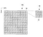
- FIG. 2 is a diagram showing the arrangement of the antenna panel 30 in the conventional power transmission antenna 100.
- the antenna panel 30 is disposed on all the rows and columns constituting the plane, that is, on the entire surface.
- FIG. 3 is a diagram illustrating a beam shape of an electromagnetic wave transmitted from the conventional power transmission antenna 100.
- FIG. 3 is a simulation result of the beam shape of the electromagnetic wave at a position 30 km away from the power transmission antenna 100.
- the beam shape of the conventional power transmission antenna 100 is a mountain shape with the center of the power transmission antenna 100 as a vertex. It is suitable that such a beam shape is received by the power receiving antenna 16.
- the antenna panel 30 is disposed on the entire surface of the power transmission antenna 100, the number of antenna elements 32 increases, and the mass and cost increase.
- the power transmission antenna 14 according to the first embodiment includes an intermittent portion in which one or more antenna panels 30 are arranged for each row and column constituting the plane and the antenna panel 30 is not arranged.
- One or more 31 is arranged, and the antenna panel 30 is arranged symmetrically in the row direction and the column direction.
- the power receiving antenna 16 is different from the power transmitting antenna 14 according to the first embodiment in that an antenna panel 30 is disposed on the entire surface.
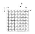
- the area indicated by hatching is the arrangement position of the antenna panel 30, and the area not hatched is the intermittent portion 31.
- the vertical and horizontal sizes of the intermittent portion 31 are equal to the vertical and horizontal sizes of the antenna panel 30.
- the symmetric arrangement will be described in detail.
- the antenna panel 30 is arranged on a line object around the center line in the row direction and the center line in the column direction of the planar power transmission antenna 14.
- the antenna panel 30 is not adjacent in the row direction and the column direction, and the antenna panel 30 and the intermittent portion 31 are arranged at equal intervals. That is, the antenna panel 30 is arranged in a so-called checkered pattern.
- the power transmission antenna 14 includes the antenna panel 30 arranged in a checkered pattern, so that one or more antenna panels 30 and one or more intermittent portions 31 are arranged for each row.
- the panel 30 is configured to be arranged symmetrically in the row direction and the column direction.
- the power transmission antenna 14 can reduce the number of the antenna panels 30 compared with the case where the antenna panels 30 are arranged on the entire surface.
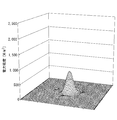
- FIG. 5 is a diagram showing a beam shape of an electromagnetic wave transmitted from the power transmission antenna 14 according to the first embodiment.
- FIG. 5 shows a simulation result of the beam shape of the electromagnetic wave at a position 30 km away from the power transmission antenna 14.
- the beam shape of the power transmission antenna 14 is a mountain shape with the center of the power transmission antenna 14 at the top. This beam shape is the same as the beam shape of the conventional power transmission antenna 100.
- the antenna panel 30 is arranged on the entire surface by arranging the antenna panel 30 symmetrically in the row direction and the column direction in a checkered pattern as shown in FIG. As in the case, the electromagnetic wave can be transmitted without breaking the beam shape.
- the beam intensity represented by the power density may be smaller than that of the conventional power transmission antenna 100.
- the beam intensity can be made equal to the beam intensity of the conventional power transmission antenna 14B by increasing the intensity of the electromagnetic wave transmitted by each antenna panel 30 constituting the power transmission antenna 14.
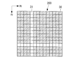
- FIG. 6 is a diagram showing an example of the power transmitting antenna 200 in which there are rows and columns in which no antenna panel 30 is arranged. Such an arrangement of the antenna panel 30 is not suitable for power transmission by the remote island power transmission system 10 because the beam shape of the electromagnetic wave collapses.
- FIG. 7 is a schematic diagram of a beam shape at the position of the cross section of the power transmitting antenna 14 and the power receiving antenna 16 according to the first embodiment.
- the antenna panel 30B indicated by the broken line in FIG. 7 is arranged one behind the antenna panel 30A indicated by the solid line, and shows that the antenna panel 30 constituting the power transmission antenna 14 is arranged in a checkered pattern. Yes.
- the vertical and horizontal lengths of the antenna panel 30 constituting the power transmitting antenna 14 are, for example, 5 m ⁇ 5 m, and the distance between the power transmitting antenna 14 and the power receiving antenna 16 is, for example, 10 km.
- the distance between the power transmitting antenna 14 and the power receiving antenna 16 is sufficiently longer than the vertical and horizontal lengths of the antenna panel 30.
- the antenna panel 30 constituting the power transmitting antenna 14 is arranged in a checkered pattern, for example, the antenna panel 30 is arranged symmetrically in the row direction and the column direction.
- the electromagnetic waves transmitted from the nearby antenna panel 30 are averaged.
- the power receiving antenna 16 is hardly affected by the arrangement of the antenna panel 30 and the beam shape does not collapse.
- FIG. 6 when the antenna panel 30 is not arranged symmetrically in the row direction and the column direction, and there is a row and a column in which no antenna panel 30 is arranged in the power transmission antenna 14, the electromagnetic wave intensity is increased. A small region is generated, and this region becomes a singular point, causing the beam shape of the electromagnetic wave to collapse.
- the antenna panel 30 is arranged in a planar shape, and one or more antenna panels 30 are arranged for each row and column constituting the plane and the antenna is arranged.
- One or more intermittent portions 31 where the panel 30 is not disposed are disposed, and the antenna panel 30 is disposed symmetrically in the row direction and the column direction.
- the configuration of the remote island power transmission system 10 according to the second embodiment is the same as the configuration of the remote island power transmission system 10 according to the first embodiment shown in FIG.
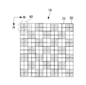
- FIG. 8 is a view showing the arrangement of the antenna panel 30 in the power transmission antenna 14 according to the second embodiment.
- the power transmission antenna 14 includes two or more adjacent antenna panels 30 as an antenna panel set 40, the antenna panel set 40 is not adjacent in the row direction and the column direction, and the antenna panel set 40.
- the intermittent part 31 is arrange
- the power transmission antenna 14 is arranged with one or more antenna panels 30 and one or more intermittent portions 31 for each row by arranging the antenna panel set 40 in a checkered pattern.
- the antenna panel 30 is configured to be arranged symmetrically in the row direction and the column direction.
- the power transmission antenna 14 can reduce the number of the antenna panels 30 compared with the case where the antenna panels 30 are arranged on the entire surface.
- the antenna panel set 40 is constituted by four adjacent antenna panels 30. However, this is an example, and the antenna panel set 40 may be configured by five or more adjacent antenna panels 30 or less.
- FIG. 9 is a diagram showing a beam shape of an electromagnetic wave transmitted from the power transmission antenna 14 according to the second embodiment.
- FIG. 9 is a simulation result of the beam shape of the electromagnetic wave at a position 30 km away from the power transmission antenna 14.
- the beam shape of the power transmission antenna 14 is a mountain shape with the center of the power transmission antenna 14 at the top. This beam shape is the same as the beam shape of the conventional power transmission antenna 100.
- the power transmission antenna 14 according to the second embodiment has the beam shape similar to the case where the antenna panel 30 is arranged on the entire surface by arranging the antenna panel 30 symmetrically in the row direction and the column direction. Electromagnetic waves can be transmitted without breaking down.
- the configuration of the remote island power transmission system 10 according to the third embodiment is the same as the configuration of the remote island power transmission system 10 according to the first embodiment shown in FIG.
- the antenna panel 30 are arranged for each row and column, and the antenna panels 30 are arranged symmetrically in the row direction and the column direction.
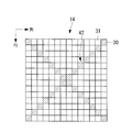
- the antenna panel 30 arranged in an X shape as shown in FIG. 10 is an antenna panel set 42, and one antenna panel set 42 is arranged.
- the X shape is a so-called slash shape, and more specifically, is a shape in which the antenna panel 30 is arranged on two diagonal lines included in, for example, a quadrangle.
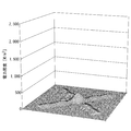
- FIG. 11 is a diagram showing a beam shape of an electromagnetic wave transmitted from the power transmission antenna 14 according to the third embodiment.
- FIG. 11 shows the simulation result of the beam shape of the electromagnetic wave at a position 30 km away from the power transmission antenna 14.
- the beam shape of the power transmission antenna 14 is a mountain shape with the center of the power transmission antenna 14 at the top. This beam shape is the same as the beam shape of the conventional power transmission antenna 100.
- the power transmission antenna 14 according to the third embodiment two antenna panels 30 are arranged for each row and column, and the antenna panels 30 are arranged symmetrically in the row direction and the column direction.
- the power transmission antenna 14 according to the third embodiment can configure the power transmission antenna 14 with the smallest number of antenna panels 30, and the beam shape is not destroyed as in the case where the antenna panel 30 is arranged on the entire surface. Electromagnetic waves can be transmitted.
- the configuration of the remote island power transmission system 10 according to the fourth embodiment is the same as the configuration of the remote island power transmission system 10 according to the first embodiment shown in FIG.
- the power transmission antenna 14 according to the fourth embodiment is configured by arranging two or more antenna panel sets 42.
- FIG. 12 is a view showing the arrangement of the antenna panel 30 in the power transmission antenna 14 according to the fourth embodiment.
- the power transmission antenna 14 according to the fourth embodiment is configured by arranging four antenna panel sets 42 as an example.
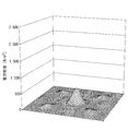
- FIG. 13 is a diagram showing a beam shape of an electromagnetic wave transmitted from the power transmission antenna 14 according to the fourth embodiment.
- FIG. 13 is a simulation result of the beam shape of the electromagnetic wave at a position 30 km away from the power transmission antenna 14.
- the beam shape of the power transmission antenna 14 is a mountain shape with the center of the power transmission antenna 14 at the top. This beam shape is the same as the beam shape of the conventional power transmission antenna 100.
- one or more antenna panels 30 are arranged for each row and the intermittent portion 31 by arranging the antenna panel set 42 in an X shape.
- One or more are arranged, and the antenna panel 30 is arranged symmetrically in the row direction and the column direction.
- the power transmission antenna 14 according to the fourth embodiment can reduce the number of antenna panels 30 without destroying the beam shape of the electromagnetic wave to be transmitted.
- this invention is not limited to this, For example, SSPS etc. transmit other electric power by electromagnetic waves, etc. It is good also as a form applied to a wireless power transmission system.
- the said embodiment demonstrated the form which made the shape of the power transmission antenna 14 and the antenna panel 30 square, this invention is not limited to this,
- the shape of the power transmission antenna 14 and the antenna panel 30 is square. Other polygonal shapes or circular shapes may be used.
- the said embodiment demonstrated the form in which the antenna panel 30 is arrange
Landscapes
- Engineering & Computer Science (AREA)
- Computer Networks & Wireless Communication (AREA)
- Power Engineering (AREA)
- Variable-Direction Aerials And Aerial Arrays (AREA)
Abstract
送信する電磁波のビーム形状を崩すことなく、アンテナ体の数を減少させる。電力を電磁波に変換して送受信する離島電力伝送システムの送電アンテナ(14)は、アンテナパネル(30)が平面状に配置され、該平面を構成する行及び列毎にアンテナパネル(30)が一つ以上配置されると共にアンテナパネル(30)が配置されない間欠部(31)が一つ以上配置され、かつアンテナパネル(30)が行方向及び列方向に対称に配置される。例えば、送電アンテナ(14)は、アンテナパネル(30)が行方向及び列方向に隣接せず、かつアンテナパネル(30)及び間欠部(31)が等間隔で配置される。
Description
本発明は、送電アンテナ及び無線電力伝送システムに関するものである。
近年、電磁波により電力を送電する無線電力伝送システムの開発が進んでいる。
この無線電力伝送システムの一例としては、宇宙空間上で太陽光発電を行い、生成した電力を位相が揃えられてビーム形成された電磁波(マイクロ波)として、宇宙空間上の送電アンテナから地上の受電アンテナへ送る宇宙太陽発電システム(Space Solar Power System、以下、「SSPS」という。)や、送電アンテナから電磁波を離島に配置される受電アンテナへ送電する離島電力伝送システム等が挙げられる。
この無線電力伝送システムの一例としては、宇宙空間上で太陽光発電を行い、生成した電力を位相が揃えられてビーム形成された電磁波(マイクロ波)として、宇宙空間上の送電アンテナから地上の受電アンテナへ送る宇宙太陽発電システム(Space Solar Power System、以下、「SSPS」という。)や、送電アンテナから電磁波を離島に配置される受電アンテナへ送電する離島電力伝送システム等が挙げられる。
特許文献1には、アンテナ素子の数が多いアレーアンテナでは、アンテナ素子の励振や給電線の配線(給電回路)が複雑になるため、電波エネルギの給電が行われないアンテナ素子(無給電素子)を所定の位置に配置することにより、アンテナ利得を低減させることなく給電回路を簡略化することが記載されている。
一方で、アンテナ素子の数が多くなると、製造コストや無線電力伝送システム全体としての質量が増加してしまう。そして、特許文献1に記載されているように、無給電素子を増やしたとしても、アンテナ素子そのものを減少させるわけでないため、製造コストや質量の増加を抑制することはできない。
本発明は、このような事情に鑑みてなされたものであって、送信する電磁波のビーム形状を崩すことなく、アンテナパネルの数を減少させることができる、送電アンテナ及び無線電力伝送システムを提供することを目的とする。
上記課題を解決するために、本発明の送電アンテナ及び無線電力伝送システムは以下の手段を採用する。
本発明の第一態様に係る送電アンテナは、電力を電磁波に変換して送受信する無線電力伝送システムの送電アンテナであって、アンテナ体が平面状に配置され、該平面を構成する行及び列毎にアンテナ体が一つ以上配置されると共に該アンテナ体が配置されない間欠部が一つ以上配置され、かつ該アンテナ体が行方向及び列方向に対称に配置される。
本構成に係る送電アンテナは、電力を電磁波に変換して送受信する無線電力伝送システムの送電アンテナである。
送電アンテナは、アンテナ体が平面状に配置され、該平面を構成する行及び列毎にアンテナ体が一つ以上配置されると共に該アンテナ体が配置されない間欠部が一つ以上配置される。これにより、本構成は、送電アンテナの行及び列を全てに、すなわち全面にアンテナ体を配置させた場合に比べて、アンテナ体の数を減少させることができる。
また、アンテナ体は、行方向及び列方向に対称に配置される。これにより、全面にアンテナ体を配置させた場合と同様に、ビーム形状を崩すことなく電磁波を送信することができる。
このように、本構成は、送信する電磁波のビーム形状を崩すことなく、アンテナ体の数を減少させることができる。
上記第一態様では、前記アンテナ体が行方向及び列方向に隣接せず、かつ前記アンテナ体及び前記間欠部が等間隔で配置されることが好ましい。
本構成によれば、アンテナ体は、所謂、市松模様状に配置されるので、簡易な構成で、送信する電磁波のビーム形状を崩すことなく、アンテナ体の数を減少させることができる。
上記第一態様では、互いに隣接する2つ以上の前記アンテナ体を組とし、かつ該組及び前記間欠部が等間隔で配置されることが好ましい。
本構成によれば、アンテナ体の組は、所謂、市松模様状に配置されるので、簡易な構成で、送信する電磁波のビーム形状を崩すことなく、アンテナ体の数を減少させることができる。
上記第一態様では、前記アンテナ体が行及列毎に2つ配置されると共に、該アンテナ体が行方向及び列方向に対称に配置されることが好ましい。
本構成によれば、送信する電磁波のビーム形状を崩すことなく、最も少ないアンテナ体の数で送電アンテナを構成できる。
上記第一態様では、X字状に配置される前記アンテナ体を組とし、前記組が少なくとも1つ以上配置されることが好ましい。
本構成によれば、アンテナ体の組は、所謂、たすき掛け状に配置されるので、簡易な構成で、送信する電磁波のビーム形状を崩すことなく、アンテナ体の数を減少させることができる。
本発明の第二態様に係る無線電力伝送システムは、電磁波を送信する上記記載の送電アンテナと、前記送電アンテナから送信された電磁波を受信する受電アンテナと、を備える。
本発明によれば、送信する電磁波のビーム形状を崩すことなく、アンテナパネルの数を減少させることができる、という優れた効果を有する。
以下に、本発明に係る送電アンテナ及び無線電力伝送システムの一実施形態について、図面を参照して説明する。
〔第1実施形態〕
以下、本発明の第1実施形態について説明する。本第1実施形態では、本発明を離島電力伝送システムに適用した場合を例に挙げて説明する。
以下、本発明の第1実施形態について説明する。本第1実施形態では、本発明を離島電力伝送システムに適用した場合を例に挙げて説明する。
図1は、本第1実施形態に係る離島電力伝送システム10の概略図である。本第1実施形態に係る離島電力伝送システム10は、一例として、送電設備12が、電力を電磁波(例えばマイクロ波)に変換し、電磁波を送電アンテナ14から離島に配置される受電アンテナ16を備えた受電設備18へ向けて送電する。受電設備18は、受電アンテナ16で受電したマイクロ波を再び電力に変換し、送電網20へ送電する。なお、送電アンテナ14及び受電アンテナ16は、一例としてフェーズドアレイアンテナである。
送電アンテナ14は、例えば平面状にアンテナ体(以下、「アンテナパネル」という。)30(図2や図4参照)が配置される。なお、平面状とは、略平面である場合も含み、例えば、送電アンテナ14が湾曲していてもよい。そして、各アンテナパネル30には、複数のアンテナ素子32(図2参照)が平面状に所定の距離間隔で配列されている。
図2は、従来の送電アンテナ100におけるアンテナパネル30の配置を示した図である。従来の送電アンテナ100は、平面を構成する行及び列を全てに、すなわち全面にアンテナパネル30が配置される。
図3は、従来の送電アンテナ100から送信される電磁波のビーム形状を示した図である。なお、図3は、送電アンテナ100から30km離れた位置における電磁波のビーム形状のシミュレーション結果である。
図3に示されるように、従来の送電アンテナ100のビーム形状は、送電アンテナ100の中心を頂点とした山形となっている。このようなビーム形状が、受電アンテナ16で受信されることが適している。
図3に示されるように、従来の送電アンテナ100のビーム形状は、送電アンテナ100の中心を頂点とした山形となっている。このようなビーム形状が、受電アンテナ16で受信されることが適している。
しかしながら、送電アンテナ100は、その全面にアンテナパネル30が配置されているため、アンテナ素子32の数が増加し、質量やコストが増加する。
そこで、本第1実施形態に係る送電アンテナ14は、図4に示されるように、平面を構成する行及び列毎にアンテナパネル30が一つ以上配置されると共にアンテナパネル30が配置されない間欠部31が一つ以上配置され、かつアンテナパネル30が行方向及び列方向に対称に配置される。
なお、受電アンテナ16は、本第1実施形態に係る送電アンテナ14とは異なり、全面にアンテナパネル30が配置されている。
なお、受電アンテナ16は、本第1実施形態に係る送電アンテナ14とは異なり、全面にアンテナパネル30が配置されている。
図4の例では、ハッチングで示される領域がアンテナパネル30の配置位置であり、ハッチングされていない領域が間欠部31である。
なお、間欠部31の縦横の大きさは、アンテナパネル30の縦横の大きさと同等である。また、上記対称な配置を詳述すると、平面状の送電アンテナ14の行方向の中心線及び列方向の中心線を軸にアンテナパネル30が線対象に配置されることである。
なお、間欠部31の縦横の大きさは、アンテナパネル30の縦横の大きさと同等である。また、上記対称な配置を詳述すると、平面状の送電アンテナ14の行方向の中心線及び列方向の中心線を軸にアンテナパネル30が線対象に配置されることである。
図4に示されるように、送電アンテナ14は、アンテナパネル30が行方向及び列方向に隣接せず、かつアンテナパネル30及び間欠部31が等間隔で配置される。すなわち、アンテナパネル30は、所謂、市松模様状に配置される。
このように、送電アンテナ14は、市松模様状にアンテナパネル30が配置されることによって、行及列毎にアンテナパネル30が一つ以上配置されると共に間欠部31が一つ以上配置され、アンテナパネル30が行方向及び列方向に対称に配置される構成とされる。
これにより、送電アンテナ14は、全面にアンテナパネル30を配置させた場合に比べて、アンテナパネル30の数を減少させることができる。
図5は、本第1実施形態に係る送電アンテナ14から送信される電磁波のビーム形状を示した図である。なお、図5は、送電アンテナ14から30km離れた位置における電磁波のビーム形状のシミュレーション結果である。
図5に示されるように、送電アンテナ14のビーム形状は、送電アンテナ14の中心を頂点とした山形となっている。このビーム形状は、従来の送電アンテナ100のビーム形状と同様である。
本第1実施形態に係る送電アンテナ14は、図4に示されるように市松模様状にアンテナパネル30が行方向及び列方向に対称に配置されることにより、全面にアンテナパネル30を配置させた場合と同様に、ビーム形状を崩すことなく電磁波を送信することができる。
なお、アンテナパネル30の数は減少しているため、例えば電力密度で表わされるビーム強度は、従来の送電アンテナ100に比べて小さくなる場合がある。このような場合は、送電アンテナ14を構成する各アンテナパネル30が送信する電磁波の強度を増加させることで、ビーム強度を従来の送電アンテナ14Bのビーム強度と同等とすることができる。
ここで、図6は、アンテナパネル30が1枚も配置されない行及び列が存在する送電アンテナ200の一例を示した図である。このようなアンテナパネル30の配置では、電磁波のビーム形状が崩れてしまい、離島電力伝送システム10による送電に適さない。
この理由は、以下の通りである。
図7は、本第1実施形態に係る送電アンテナ14の横断面及び受電アンテナ16の位置におけるビーム形状の模式図である。図7における破線で示されるアンテナパネル30Bは、実線で示されるアンテナパネル30Aに対して一つ奥に配置され、送電アンテナ14を構成するアンテナパネル30が市松模様状に配置さていることを示している。
送電アンテナ14を構成するアンテナパネル30の縦横の長さが例えば5m×5mであり、送電アンテナ14と受電アンテナ16との距離が例えば10kmである。このように、送電アンテナ14と受電アンテナ16との距離は、アンテナパネル30の縦横の長さに対して十分に長い。
図7は、本第1実施形態に係る送電アンテナ14の横断面及び受電アンテナ16の位置におけるビーム形状の模式図である。図7における破線で示されるアンテナパネル30Bは、実線で示されるアンテナパネル30Aに対して一つ奥に配置され、送電アンテナ14を構成するアンテナパネル30が市松模様状に配置さていることを示している。
送電アンテナ14を構成するアンテナパネル30の縦横の長さが例えば5m×5mであり、送電アンテナ14と受電アンテナ16との距離が例えば10kmである。このように、送電アンテナ14と受電アンテナ16との距離は、アンテナパネル30の縦横の長さに対して十分に長い。
このような場合、受電アンテナ16にとっては、送電アンテナ14を構成するアンテナパネル30が例えば市松模様状に配置されていたとしても、アンテナパネル30が行方向及び列方向に対称に配置されているため、近隣のアンテナパネル30から送電される電磁波が平均化される。このため、受電アンテナ16は、アンテナパネル30の配置の影響をほとんど受けることが無く、ビーム形状が崩れない。
一方、図6に示されるように、アンテナパネル30が行方向及び列方向に対称に配置されず、送電アンテナ14にアンテナパネル30が1枚も配置されない行及び列が存在すると、電磁波の強度が小さい領域が生じ、その領域が特異点となり、電磁波のビーム形状が崩れる原因となる。
一方、図6に示されるように、アンテナパネル30が行方向及び列方向に対称に配置されず、送電アンテナ14にアンテナパネル30が1枚も配置されない行及び列が存在すると、電磁波の強度が小さい領域が生じ、その領域が特異点となり、電磁波のビーム形状が崩れる原因となる。
以上説明したように、本第1実施形態に係る送電アンテナ14は、アンテナパネル30が平面状に配置され、該平面を構成する行及び列毎にアンテナパネル30が一つ以上配置されると共にアンテナパネル30が配置されない間欠部31が一つ以上配置され、かつアンテナパネル30が行方向及び列方向に対称に配置される。これによって、本第1実施形態に係る送電アンテナ14は、送信する電磁波のビーム形状を崩すことなく、アンテナパネル30の数を減少させることができる。
〔第2実施形態〕
以下、本発明の第2実施形態について説明する。
以下、本発明の第2実施形態について説明する。
なお、本第2実施形態に係る離島電力伝送システム10の構成は、図1に示される第1実施形態に係る離島電力伝送システム10の構成と同様であるので説明を省略する。
図8は、本第2実施形態に係る送電アンテナ14におけるアンテナパネル30の配置を示した図である。
図8に示されるように、送電アンテナ14は、互いに隣接する2つ以上のアンテナパネル30をアンテナパネル組40とし、アンテナパネル組40が行方向及び列方向に隣接せず、かつアンテナパネル組40及び間欠部31が等間隔で配置される。
すなわち、アンテナパネル組40は、所謂、市松模様状に配置される。
すなわち、アンテナパネル組40は、所謂、市松模様状に配置される。
このように、送電アンテナ14は、市松模様状にアンテナパネル組40が配置されることによって、行及列毎にアンテナパネル30が一つ以上配置されると共に間欠部31が一つ以上配置され、アンテナパネル30が行方向及び列方向に対称に配置される構成とされる。
これにより、送電アンテナ14は、全面にアンテナパネル30を配置させた場合に比べて、アンテナパネル30の数を減少させることができる。
なお、図8では、アンテナパネル組40が、隣接する4つのアンテナパネル30によって構成されている。しかし、これは一例であり、アンテナパネル組40が、隣接する5つ以上又は3つ以下のアンテナパネル30によって構成されてもよい。
図9は、本第2実施形態に係る送電アンテナ14から送信される電磁波のビーム形状を示した図である。なお、図9は、送電アンテナ14から30km離れた位置における電磁波のビーム形状のシミュレーション結果である。
図9に示されるように、送電アンテナ14のビーム形状は、送電アンテナ14の中心を頂点とした山形となっている。このビーム形状は、従来の送電アンテナ100のビーム形状と同様である。
このように、本第2実施形態に係る送電アンテナ14は、アンテナパネル30が行方向及び列方向に対称に配置されることにより、全面にアンテナパネル30を配置させた場合と同様に、ビーム形状を崩すことなく電磁波を送信することができる。
〔第3実施形態〕
以下、本発明の第3実施形態について説明する。
以下、本発明の第3実施形態について説明する。
なお、本第3実施形態に係る離島電力伝送システム10の構成は、図1に示される第1実施形態に係る離島電力伝送システム10の構成と同様であるので説明を省略する。
本第3実施形態に係る送電アンテナ14は、アンテナパネル30が行及列毎に2つ配置されると共に、該アンテナパネル30が行方向及び列方向に対称に配置されている。
この配置の一例としては、図10に示されるようにX字状に配置されるアンテナパネル30をアンテナパネル組42とし、アンテナパネル組42が1つ配置されて構成される。なお、X字状とは、所謂、たすき掛け状であり、より具体的には、例えば四角形に含まれる2つの対角線上にアンテナパネル30が配列された形状である。
この配置の一例としては、図10に示されるようにX字状に配置されるアンテナパネル30をアンテナパネル組42とし、アンテナパネル組42が1つ配置されて構成される。なお、X字状とは、所謂、たすき掛け状であり、より具体的には、例えば四角形に含まれる2つの対角線上にアンテナパネル30が配列された形状である。
図11は、本第3実施形態に係る送電アンテナ14から送信される電磁波のビーム形状を示した図である。なお、図11は、送電アンテナ14から30km離れた位置における電磁波のビーム形状のシミュレーション結果である。
図11に示されるように、送電アンテナ14のビーム形状は、送電アンテナ14の中心を頂点とした山形となっている。このビーム形状は、従来の送電アンテナ100のビーム形状と同様である。
このように、本第3実施形態に係る送電アンテナ14は、アンテナパネル30が行及列毎に2つ配置されると共に、該アンテナパネル30が行方向及び列方向に対称に配置される。これにより、本第3実施形態に係る送電アンテナ14は、最も少ないアンテナパネル30の数で送電アンテナ14を構成でき、全面にアンテナパネル30を配置させた場合と同様に、ビーム形状を崩すことなく電磁波を送信することができる。
〔第4実施形態〕
以下、本発明の第4実施形態について説明する。
以下、本発明の第4実施形態について説明する。
なお、本第4実施形態に係る離島電力伝送システム10の構成は、図1に示される第1実施形態に係る離島電力伝送システム10の構成と同様であるので説明を省略する。
本第4実施形態に係る送電アンテナ14は、アンテナパネル組42が2つ以上配置されて構成される。
図12は、本第4実施形態に係る送電アンテナ14におけるアンテナパネル30の配置を示した図である。
図12に示されるように、本第4実施形態に係る送電アンテナ14は、一例として4つのアンテナパネル組42が配置されて構成される。
図13は、本第4実施形態に係る送電アンテナ14から送信される電磁波のビーム形状を示した図である。なお、図13は、送電アンテナ14から30km離れた位置における電磁波のビーム形状のシミュレーション結果である。
図13に示されるように、送電アンテナ14のビーム形状は、送電アンテナ14の中心を頂点とした山形となっている。このビーム形状は、従来の送電アンテナ100のビーム形状と同様である。
このように、本第4実施形態に係る送電アンテナ14は、X字状にアンテナパネル組42が配置されることによって、行及列毎にアンテナパネル30が一つ以上配置されると共に間欠部31が一つ以上配置され、アンテナパネル30が行方向及び列方向に対称に配置される構成とされる。これにより、本第4実施形態に係る送電アンテナ14は、送信する電磁波のビーム形状を崩すことなく、アンテナパネル30の数を減少させることができる。
以上、本発明を、上記各実施形態を用いて説明したが、本発明の技術的範囲は上記実施形態に記載の範囲には限定されない。発明の要旨を逸脱しない範囲で上記各実施形態に多様な変更又は改良を加えることができ、該変更又は改良を加えた形態も本発明の技術的範囲に含まれる。
また、上記実施形態では、本発明を離島電力伝送システム10に適用する形態について説明したが、本発明は、これに限定されるものではなく、例えば、SSPS等、電磁波により電力を送電する他の無線電力伝送システムに適用する形態としてもよい。
また、上記実施形態では、送電アンテナ14及びアンテナパネル30の形状を四角形とする形態について説明したが、本発明は、これに限定されるものではなく、送電アンテナ14及びアンテナパネル30の形状を四角形以外の多角形や円形とする形態としてもよい。
また、上記実施形態では、アンテナパネル30が規則性を持って配置される形態について説明したが、本発明は、これに限定されるものではなく、アンテナパネル30がランダムに配置される形態としてもよい。
10 離島電力伝送システム
14 送電アンテナ
16 受電アンテナ
30 アンテナパネル
31 間欠部
40 アンテナパネル組
42 アンテナパネル組
14 送電アンテナ
16 受電アンテナ
30 アンテナパネル
31 間欠部
40 アンテナパネル組
42 アンテナパネル組
Claims (6)
- 電力を電磁波に変換して送受信する無線電力伝送システムの送電アンテナであって、
アンテナ体が平面状に配置され、該平面を構成する行及び列毎にアンテナ体が一つ以上配置されると共に該アンテナ体が配置されない間欠部が一つ以上配置され、かつ該アンテナ体が行方向及び列方向に対称に配置される送電アンテナ。 - 前記アンテナ体が行方向及び列方向に隣接せず、かつ前記アンテナ体及び前記間欠部が等間隔で配置される請求項1記載の送電アンテナ。
- 互いに隣接する2つ以上の前記アンテナ体を組とし、かつ該組及び前記間欠部が等間隔で配置される請求項1記載の送電アンテナ。
- 前記アンテナ体が行及列毎に2つ配置されると共に、該アンテナ体が行方向及び列方向に対称に配置される請求項1記載の送電アンテナ。
- X字状に配置される前記アンテナ体を組とし、前記組が少なくとも1つ以上配置される請求項1記載の送電アンテナ。
- 電磁波を送信する請求項1から請求項5の何れか1項記載の送電アンテナと、
前記送電アンテナから送信された電磁波を受信する受電アンテナと、
を備える無線電力伝送システム。
Applications Claiming Priority (2)
| Application Number | Priority Date | Filing Date | Title |
|---|---|---|---|
| JP2013012154A JP6095992B2 (ja) | 2013-01-25 | 2013-01-25 | 送電アンテナ及び無線電力伝送システム |
| JP2013-012154 | 2013-01-25 |
Publications (1)
| Publication Number | Publication Date |
|---|---|
| WO2014115481A1 true WO2014115481A1 (ja) | 2014-07-31 |
Family
ID=51227281
Family Applications (1)
| Application Number | Title | Priority Date | Filing Date |
|---|---|---|---|
| PCT/JP2013/085014 Ceased WO2014115481A1 (ja) | 2013-01-25 | 2013-12-26 | 送電アンテナ及び無線電力伝送システム |
Country Status (2)
| Country | Link |
|---|---|
| JP (1) | JP6095992B2 (ja) |
| WO (1) | WO2014115481A1 (ja) |
Families Citing this family (1)
| Publication number | Priority date | Publication date | Assignee | Title |
|---|---|---|---|---|
| JP7259275B2 (ja) * | 2018-11-13 | 2023-04-18 | 三菱電機株式会社 | フェイズドアレイアンテナ装置、電力伝送システム、ビームパターン形成方法及び電力伝送方法 |
Citations (6)
| Publication number | Priority date | Publication date | Assignee | Title |
|---|---|---|---|---|
| JPH06253477A (ja) * | 1993-02-25 | 1994-09-09 | Rocket Syst:Kk | 太陽発電の発送電装置 |
| JPH1117446A (ja) * | 1997-06-27 | 1999-01-22 | Mitsubishi Electric Corp | アンテナ装置 |
| JP2000278888A (ja) * | 1999-03-19 | 2000-10-06 | Toshiba Corp | 衛星間電力伝送システム |
| JP2002335124A (ja) * | 2001-03-09 | 2002-11-22 | Hitachi Kokusai Electric Inc | Its用基地局アンテナ装置及びアンテナの形成方法 |
| JP2004088443A (ja) * | 2002-08-27 | 2004-03-18 | Mitsubishi Heavy Ind Ltd | マイクロ波による電力伝送方法および電力伝送システム |
| JP2008092703A (ja) * | 2006-10-03 | 2008-04-17 | Toyota Motor Corp | 非接触給電システム |
-
2013
- 2013-01-25 JP JP2013012154A patent/JP6095992B2/ja not_active Expired - Fee Related
- 2013-12-26 WO PCT/JP2013/085014 patent/WO2014115481A1/ja not_active Ceased
Patent Citations (6)
| Publication number | Priority date | Publication date | Assignee | Title |
|---|---|---|---|---|
| JPH06253477A (ja) * | 1993-02-25 | 1994-09-09 | Rocket Syst:Kk | 太陽発電の発送電装置 |
| JPH1117446A (ja) * | 1997-06-27 | 1999-01-22 | Mitsubishi Electric Corp | アンテナ装置 |
| JP2000278888A (ja) * | 1999-03-19 | 2000-10-06 | Toshiba Corp | 衛星間電力伝送システム |
| JP2002335124A (ja) * | 2001-03-09 | 2002-11-22 | Hitachi Kokusai Electric Inc | Its用基地局アンテナ装置及びアンテナの形成方法 |
| JP2004088443A (ja) * | 2002-08-27 | 2004-03-18 | Mitsubishi Heavy Ind Ltd | マイクロ波による電力伝送方法および電力伝送システム |
| JP2008092703A (ja) * | 2006-10-03 | 2008-04-17 | Toyota Motor Corp | 非接触給電システム |
Also Published As
| Publication number | Publication date |
|---|---|
| JP2014143641A (ja) | 2014-08-07 |
| JP6095992B2 (ja) | 2017-03-15 |
Similar Documents
| Publication | Publication Date | Title |
|---|---|---|
| JP5969698B2 (ja) | アンテナアレイ、アンテナ装置及び基地局 | |
| CN108432088B (zh) | 具有子阵列的相控阵天线 | |
| JP6232174B2 (ja) | マルチビームアンテナシステム | |
| EP3231037B1 (en) | High coverage antenna array and method using grating lobe layers | |
| JP6647121B2 (ja) | アンテナ装置、レーダ装置および無線通信装置 | |
| CN107230843A (zh) | 一种基于不规则子阵排列的相控阵天线 | |
| JP2011244440A5 (ja) | マルチビームアンテナシステム | |
| CN106252903A (zh) | 一种双频两波束天线阵列及双频两波束天线 | |
| CN109037885A (zh) | 一种基于子阵错位的星载sar相控阵天线 | |
| CN103840261A (zh) | 天线装置和调整天线波束的方法 | |
| JP6095992B2 (ja) | 送電アンテナ及び無線電力伝送システム | |
| JP6409676B2 (ja) | 衛星通信用アレイアンテナおよびアンテナ | |
| JP4724862B2 (ja) | アレーアンテナ | |
| JP2009111662A (ja) | 周波数共用アレイアンテナ | |
| CN202871960U (zh) | 全向赋形微带阵列天线 | |
| JP6121095B2 (ja) | 送電装置及び無線電力伝送システム | |
| JP7316404B2 (ja) | アンテナアレイ装置 | |
| JP2009111661A (ja) | アレイアンテナ | |
| JP5314315B2 (ja) | アレーアンテナ | |
| JP2010057091A (ja) | アレーアンテナ | |
| JP6499103B2 (ja) | アンテナ装置 | |
| KR20150045303A (ko) | 혼 배열 안테나 | |
| JP6245561B2 (ja) | アンテナ装置 | |
| WO2013099997A1 (ja) | 受電装置及び無線電力伝送システム | |
| JP7698717B2 (ja) | アンテナ装置及び無線通信装置 |
Legal Events
| Date | Code | Title | Description |
|---|---|---|---|
| 121 | Ep: the epo has been informed by wipo that ep was designated in this application |
Ref document number: 13872456 Country of ref document: EP Kind code of ref document: A1 |
|
| NENP | Non-entry into the national phase |
Ref country code: DE |
|
| 122 | Ep: pct application non-entry in european phase |
Ref document number: 13872456 Country of ref document: EP Kind code of ref document: A1 |