WO2014112425A1 - フラックス転写シート、フラックス付着方法およびろう付け方法 - Google Patents
フラックス転写シート、フラックス付着方法およびろう付け方法 Download PDFInfo
- Publication number
- WO2014112425A1 WO2014112425A1 PCT/JP2014/050245 JP2014050245W WO2014112425A1 WO 2014112425 A1 WO2014112425 A1 WO 2014112425A1 JP 2014050245 W JP2014050245 W JP 2014050245W WO 2014112425 A1 WO2014112425 A1 WO 2014112425A1
- Authority
- WO
- WIPO (PCT)
- Prior art keywords
- flux
- film layer
- layer
- brazing
- sheet
- Prior art date
- Legal status (The legal status is an assumption and is not a legal conclusion. Google has not performed a legal analysis and makes no representation as to the accuracy of the status listed.)
- Ceased
Links
Images







Classifications
-
- B—PERFORMING OPERATIONS; TRANSPORTING
- B23—MACHINE TOOLS; METAL-WORKING NOT OTHERWISE PROVIDED FOR
- B23K—SOLDERING OR UNSOLDERING; WELDING; CLADDING OR PLATING BY SOLDERING OR WELDING; CUTTING BY APPLYING HEAT LOCALLY, e.g. FLAME CUTTING; WORKING BY LASER BEAM
- B23K1/00—Soldering, e.g. brazing, or unsoldering
- B23K1/19—Soldering, e.g. brazing, or unsoldering taking account of the properties of the materials to be soldered
-
- B—PERFORMING OPERATIONS; TRANSPORTING
- B23—MACHINE TOOLS; METAL-WORKING NOT OTHERWISE PROVIDED FOR
- B23K—SOLDERING OR UNSOLDERING; WELDING; CLADDING OR PLATING BY SOLDERING OR WELDING; CUTTING BY APPLYING HEAT LOCALLY, e.g. FLAME CUTTING; WORKING BY LASER BEAM
- B23K1/00—Soldering, e.g. brazing, or unsoldering
- B23K1/20—Preliminary treatment of work or areas to be soldered, e.g. in respect of a galvanic coating
- B23K1/203—Fluxing, i.e. applying flux onto surfaces
-
- B—PERFORMING OPERATIONS; TRANSPORTING
- B23—MACHINE TOOLS; METAL-WORKING NOT OTHERWISE PROVIDED FOR
- B23K—SOLDERING OR UNSOLDERING; WELDING; CLADDING OR PLATING BY SOLDERING OR WELDING; CUTTING BY APPLYING HEAT LOCALLY, e.g. FLAME CUTTING; WORKING BY LASER BEAM
- B23K35/00—Rods, electrodes, materials, or media, for use in soldering, welding, or cutting
- B23K35/02—Rods, electrodes, materials, or media, for use in soldering, welding, or cutting characterised by mechanical features, e.g. shape
- B23K35/0222—Rods, electrodes, materials, or media, for use in soldering, welding, or cutting characterised by mechanical features, e.g. shape for use in soldering or brazing
- B23K35/0233—Sheets or foils
- B23K35/0238—Sheets or foils layered
-
- B—PERFORMING OPERATIONS; TRANSPORTING
- B23—MACHINE TOOLS; METAL-WORKING NOT OTHERWISE PROVIDED FOR
- B23K—SOLDERING OR UNSOLDERING; WELDING; CLADDING OR PLATING BY SOLDERING OR WELDING; CUTTING BY APPLYING HEAT LOCALLY, e.g. FLAME CUTTING; WORKING BY LASER BEAM
- B23K35/00—Rods, electrodes, materials, or media, for use in soldering, welding, or cutting
- B23K35/22—Rods, electrodes, materials, or media, for use in soldering, welding, or cutting characterised by the composition or nature of the material
- B23K35/36—Selection of non-metallic compositions, e.g. coatings or fluxes; Selection of soldering or welding materials, conjoint with selection of non-metallic compositions, both selections being of interest
- B23K35/3612—Selection of non-metallic compositions, e.g. coatings or fluxes; Selection of soldering or welding materials, conjoint with selection of non-metallic compositions, both selections being of interest with organic compounds as principal constituents
- B23K35/3613—Polymers, e.g. resins
-
- B—PERFORMING OPERATIONS; TRANSPORTING
- B23—MACHINE TOOLS; METAL-WORKING NOT OTHERWISE PROVIDED FOR
- B23K—SOLDERING OR UNSOLDERING; WELDING; CLADDING OR PLATING BY SOLDERING OR WELDING; CUTTING BY APPLYING HEAT LOCALLY, e.g. FLAME CUTTING; WORKING BY LASER BEAM
- B23K35/00—Rods, electrodes, materials, or media, for use in soldering, welding, or cutting
- B23K35/22—Rods, electrodes, materials, or media, for use in soldering, welding, or cutting characterised by the composition or nature of the material
- B23K35/36—Selection of non-metallic compositions, e.g. coatings or fluxes; Selection of soldering or welding materials, conjoint with selection of non-metallic compositions, both selections being of interest
- B23K35/362—Selection of compositions of fluxes
Definitions
- the present invention relates to a flux transfer sheet for attaching a flux to a metal, particularly aluminum, a flux attaching method and a brazing method.
- brazing is performed by attaching a flux to the surface of the metal member.
- the flux for brazing aluminum has almost no adhesion to aluminum, and the brazing failure occurs due to the flux falling off. Therefore, a paint that mixes the flux and resin binder is generated, and the paint is applied to the surface of the aluminum member. It has been proposed to prevent flux from falling off (for example, Patent Document 1).
- the aluminum member may be deformed such as strain.
- an object of the present invention is to provide a flux adhering method and a flux transfer sheet capable of easily adhering a flux to a metal, particularly aluminum.
- the present invention has the configurations described in [1] to [18] below.
- a first release film layer is provided on the opposite side of the base film layer from the flux layer, wherein a second release film layer having a lower release property than the first release film layer is provided between the base film layer and the flux layer.
- a brazing method comprising assembling the metal member to which the flux layer has been transferred and brazing.
- a sheet-like base film layer A film layer containing a powdered or particulate brazing material, a powdered or particulate flux and a resin binder, and laminated on the base film layer; With A brazing material transfer sheet, wherein the coating layer is transferred onto the surface of a metal member.
- a first release film layer is provided on the side opposite to the coating layer across the base film layer, 9.
- Transfer sheet is provided.
- brazing material transfer sheet according to any one of claims 8 to 11, wherein the metal member is an aluminum member.
- a transfer sheet in which a coating layer comprising a powdered or particulate brazing material, a powdered or particulate flux and a resin binder is laminated on a sheet-like base film layer, The transfer sheet is transferred by bringing the transfer sheet into close contact with the surface of the metal member, A brazing method comprising assembling and brazing the metal member to which the coating layer has been transferred.
- a brazing sheet formed by brazing a brazing material on one side or both sides of a core material made of a metal material; A flux layer that includes a flux and a resin binder, and is laminated on a surface of the brazing sheet on which the brazing material is clad; A sheet-like base film layer laminated on the flux layer; With A flux transfer sheet in which the flux layer is laminated on the base film layer, A brazing sheet with flux, which is bonded to the brazing sheet.
- a brazing sheet is produced by cladding a brazing material on one side or both sides of a core made of a metal material, A flux layer containing a flux and a resin binder is formed on the surface of the brazing sheet on which the brazing material is clad, A sheet-like base film layer is laminated on the flux layer, A flux transfer sheet in which the flux layer is laminated on the base film layer, A method for producing a brazing sheet with flux, which is bonded to the brazing sheet.
- a flux layer containing a flux and a resin binder and a sheet-like base film layer are laminated on a brazing sheet obtained by cladding a brazing material on a core made of a metal material, and the base film layer is formed on the base film layer.
- the flux transfer sheet formed by laminating the flux layer is bonded to the brazing sheet, The method for producing a metal member, wherein the base film layer is peeled off from the brazing sheet after the brazing sheet is machined while the flux layer and the base film layer are laminated. .
- a sheet-like base film layer and a flux layer made of a flux and a resin binder laminated on the base film layer are provided, and the flux layer is formed on the surface of the metal member.
- a solution such as paint is applied directly to a metal member, it is easy to uniformly apply a small amount of flux to the surface of the metal member, and the time for the drying process is not required. The manufacturing time of the member can be shortened.
- the flux can be attached only to the necessary places on the surface of the transfer sheet and the metal member, and the work load is reduced because the masking work for the places where the flux does not need to be attached is reduced. Since the flux can be easily adhered simply by transferring it in close contact with the surface, it is optimal for automation.
- the flux transfer sheet since the first release film layer is provided on the side opposite to the flux layer of the base film layer, the flux transfer sheet is used in a rolled state. In this case, since the outermost flux layer is in contact with the first release film layer, even when the flux transfer sheet is unwound, the first release layer with which the surface of the flux layer is in contact. The flux transfer sheet can be peeled off without sticking to the mold film layer.
- the flux transfer sheet is peeled off in order to transfer the flux layer to the metal member.
- the flux layer can be transferred to the surface of the metal member without the flux layer being peeled off and remaining on the flux transfer sheet.
- the first release film layer is provided on the opposite side of the base film layer from the flux layer, and the first release film is provided between the base film layer and the flux layer. Since the second release film layer having lower releasability than the layer is provided, when the flux transfer sheet is used in the state of being wound in a roll shape, it is most in contact with the first release film layer.
- the flux layer located on the outer side is peeled off from the second release film layer when the flux transfer sheet is unwound, and sticks to the first release film layer with which the surface of the flux layer comes into contact. And the flux transfer sheet can be peeled off.
- the flux transfer sheet when the flux transfer sheet is peeled off in order to transfer the flux layer to the metal member, the flux layer does not peel off well and can be transferred to the surface of the metal member without remaining on the base film layer side.
- the metal member is an aluminum member
- a small amount of flux is uniformly attached to the surface of the aluminum member even though the flux has almost no adhesion to aluminum. It becomes easy and the time of a drying process becomes unnecessary, Therefore The manufacturing time of an aluminum member can be shortened.
- the flux layer on the transfer sheet is transferred to the surface of the metal member using the transfer sheet in which the flux layer composed of the flux and the resin binder is laminated on the base film layer. Therefore, unlike the case where a solution such as a paint is applied directly to the metal member, it is easy to uniformly attach the flux to the surface of the metal member, and the time for the drying process is not required, thereby reducing the manufacturing time of the metal member. It can be shortened.
- the flux can be attached only to the necessary places on the surface of the transfer sheet and the metal member, and the work load is reduced because the masking work for the places where the flux does not need to be attached is reduced. Since the flux can be easily adhered simply by transferring it in close contact with the surface, it is optimal for automation.
- the transfer of the flux layer on the transfer sheet onto the surface of the metal member is performed using the transfer sheet in which the flux layer composed of the flux and the resin binder is laminated on the base film layer. Since the metal member to which the flux layer is transferred is assembled and brazed, a small amount of flux can be evenly adhered to the surface of the metal member and brazing can be performed, and the drying process time is not required. The manufacturing time of the metal member can be shortened.
- the flux can be attached only to the necessary locations on the surface of the transfer sheet and the metal member, so there is no waste of material, and the masking work for the locations where the flux does not need to be attached becomes unnecessary, thus reducing the work load. Can do.
- a sheet-like base film layer, a powder or particulate brazing material, a powder or particulate flux and a resin binder are laminated on the base film layer.
- the coating layer is transferred to the surface of the metal member, so that the brazing sheet transfer sheet can be transferred to the surface of the metal member in close contact without using a brazing sheet. Since the brazing material can be easily adhered and the flux can be adhered, and the configuration is optimal for automation, the adhesion work of the brazing material and the flux can be simplified.
- a drying apparatus for drying the brazing material and the flux applied to the metal member at a high temperature by generating the brazing material transfer sheet in which the brazing material and the flux are made into a paint and the film layer is laminated on the base film layer in advance. This eliminates the need to reduce the scale of the entire apparatus for manufacturing the metal member, and eliminates the possibility of deformation of the metal member due to high temperature drying.
- the masking work at the locations where the brazing material and the flux do not need to be attached becomes unnecessary, thereby reducing the work load.
- the brazing material transfer sheet is wound in a roll shape
- the outermost coating layer is in contact with the first release film layer, so the surface of the coating layer is in contact even when the brazing material transfer sheet is unwound. It can be made to peel without sticking to the 1st mold release film layer.
- the coating layer is transferred to the metal member to form the brazing material transfer sheet.
- the coating layer can be transferred to the surface of the metal member without being peeled off well and remaining on the brazing material transfer sheet.
- the first release film layer is provided on the side opposite to the coating layer across the base film layer, and between the base film layer and the coating layer, Since the second release film layer having lower releasability than the first release film layer is provided, when the brazing material transfer sheet is used in the state of being wound in a roll shape, the outermost coating layer Will come into contact with the first release film layer, so that even when the brazing material transfer sheet is unwound, it does not stick to the first release film layer with which the surface of the coating layer contacts. Only the base film layer can be peeled off.
- the coating layer can be transferred to the surface of the metal member without the coating layer being peeled off and remaining on the brazing material transfer sheet.
- the metal member is an aluminum member
- a small amount of brazing material is formed on the surface of the aluminum member even though the oxide film formed on the aluminum greatly reduces the adhesion. And it becomes easy to make a flux adhere uniformly, and since the time of a drying process becomes unnecessary, the manufacturing time of an aluminum member can be shortened.
- the coating layer containing the powdered or particulate brazing material, the powdered or particulate flux, and the resin binder is laminated on the sheet-like base film layer. Since the coating layer on the transfer sheet is transferred onto the surface of the metal member using the transfer sheet, the brazing sheet transfer sheet can be easily transferred to the surface of the metal member without using a brazing sheet. Since the material can be adhered and the flux can be adhered, and the configuration is optimum for automation, the adhesion work of the brazing material and the flux can be simplified.
- a drying apparatus for drying the brazing material and the flux applied to the metal member at a high temperature by generating the brazing material transfer sheet in which the brazing material and the flux are made into a paint and the film layer is laminated on the base film layer in advance. This eliminates the need to reduce the scale of the entire apparatus for manufacturing the metal member, and eliminates the possibility of deformation of the metal member due to high temperature drying.
- the masking work at the locations where the brazing material and the flux do not need to be attached becomes unnecessary, thereby reducing the work load.
- the coating layer containing the powdered or particulate brazing material, the powdered or particulate flux, and the resin binder is laminated on the sheet-like base film layer.
- the transfer sheet is used to adhere the transfer sheet to the surface of the metal member to transfer the film layer, and the metal member to which the film layer is transferred is assembled and brazed. Simply by transferring it in close contact with the surface of a metal member, the brazing material can be easily adhered and the flux can be adhered without using a brazing sheet. Can be simplified.
- a drying apparatus for drying the brazing material and the flux applied to the metal member at a high temperature by generating the brazing material transfer sheet in which the brazing material and the flux are made into a paint and the film layer is laminated on the base film layer in advance. This eliminates the need to reduce the scale of the entire apparatus for manufacturing the metal member, and eliminates the possibility of deformation of the metal member due to high temperature drying.
- the masking work at the locations where the brazing material and the flux do not need to be attached becomes unnecessary, thereby reducing the work load.
- a brazing sheet formed by brazing a brazing material on one surface or both surfaces of a core material made of a metal material, a flux and a resin binder,
- a brazing sheet comprising a flux layer laminated on the clad surface and a sheet-like substrate film layer laminated on the flux layer, wherein the flux layer is laminated on the substrate film layer. Since the base film layer is in a state of being laminated on the outermost side until it is peeled off, and the base film layer functions as a protective layer that protects the flux layer and below, It is possible to prevent adhesion and mixing of foreign matters, and to prevent flux from falling off due to rubbing.
- the brazing sheet protected by the base film layer can be machined such as cutting, bending, punching, and pressing, and when it is machined, the outermost laminated base material Since the film layer functions as a lubricant, the amount of lubricant such as oil used is reduced, and the manufacturing cost can be reduced.
- ⁇ Flux can be attached to the brazing sheet by a simple operation of bonding the flux transfer sheet to the brazing sheet, that is, simply bonding the sheets together.
- the flux can be attached only to the necessary portions of the surface of the flux transfer sheet and the brazing sheet, and the work load is reduced because the masking operation of the portions where the flux does not need to be attached becomes unnecessary.
- the core material is aluminum
- the required amount of flux can be adhered to the surface of the aluminum even though the core has almost no adhesion to the flux. it can.
- a brazing sheet is produced by cladding a brazing material on one side or both sides of a core material made of a metal material, and a flux and a brazing sheet on the surface of the brazing sheet are clad.
- the base film layer on which the flux layer containing the resin binder is formed is laminated, and the flux transfer sheet in which the flux layer is laminated on the base film layer is bonded to the brazing sheet, so the base film layer is peeled off Until it is done, the base film layer is in the state of being laminated on the outermost side, and the base film layer functions as a protective layer that protects the flux layer and below, preventing the adhesion of dirt and foreign matter to the flux layer, In addition, it is possible to manufacture a brazing sheet with flux that prevents the flux from falling off due to rubbing. That.
- the brazing sheet protected by the base film layer can be machined such as cutting, bending, punching, and pressing, and when it is machined, the outermost laminated base material Since the film layer functions as a lubricant, the amount of lubricant such as oil used is reduced, and the manufacturing cost can be reduced.
- ⁇ Flux can be attached to the brazing sheet by a simple operation of bonding the flux transfer sheet to the brazing sheet, that is, simply bonding the sheets together.
- the flux can be attached only to the necessary portions of the surface of the flux transfer sheet and the brazing sheet, and the work load is reduced because the masking operation of the portions where the flux does not need to be attached becomes unnecessary.
- a flux layer containing a flux and a resin binder and a sheet-like base film layer are laminated on a brazing sheet obtained by cladding a brazing material on a core material made of a metal material.
- the flux transfer sheet in which the flux layer is laminated on the base film layer is bonded to the brazing sheet, and the brazing sheet machine is left in a state where the flux layer and the base film layer are bonded.
- the base film layer is peeled off from the brazing sheet, so that the brazing sheet protected by the base film layer can be machined such as cutting, bending, punching, pressing, etc.
- the outermost substrate film layer is used as a lubricant. Since capacity, the amount of a lubricant such as oil is reduced, it is possible to reduce the manufacturing cost.
- the base film layer is laminated on the outermost side until it is peeled off, and the base film layer functions as a protective layer that protects the flux layer and below. It is possible to prevent the flux from falling off due to prevention of rubs or rubbing.
- FIG. 1 is a schematic configuration diagram of the flux transfer sheet 1
- FIGS. 2 and 3 are explanatory diagrams of how to use the flux transfer sheet 1.
- the flux transfer sheet 1 of the present invention is for easily attaching a flux to the surface of a metal, particularly an aluminum member.
- brazing is performed by attaching flux to the surface of an aluminum member supplied with a brazing material having a melting point lower than that of the aluminum member in advance.
- a known technique such as a method in which the brazing material is clad on the uppermost surface of the aluminum member or a method in which the brazing material is sprayed on the surface of the aluminum member can be applied.
- the aluminum member is brazed by, for example, a brazing method using a non-corrosive flux such as a non-corrosive fluoride flux under a nitrogen gas atmosphere condition.
- a non-corrosive flux such as a non-corrosive fluoride flux under a nitrogen gas atmosphere condition.
- the flux is used in a very small amount (for example, 3 g / m 2 to 10 g / m 2 ), it should be originally mixed with a large amount of resin binder.
- the amount of the binder is too large, the component of the resin binder that does not volatilize is carbonized and causes brazing failure.
- the flux transfer sheet 1 includes a sheet-like base film layer 4 and a flux layer 2 made of a flux and a resin binder laminated on the base film layer 4.
- a second release film layer 3 made of a release film that has been subjected to a release treatment.
- the flux layer 2 is configured to be easily peeled from the base film layer 4.
- the flux transfer sheet 1 when the flux transfer sheet 1 is peeled off to transfer the flux layer 2 to a metal member, the flux layer 2 is not peeled off and remains on the flux transfer sheet 1 without being removed. It can be transferred to the surface of the member.
- the flux transfer sheet 1 is also released on the side opposite to the flux layer 2 and the second release film layer 3 (under the base film layer 4 shown in FIG. 1) with the base film layer 4 interposed therebetween.
- a first release film layer 5 made of a treated release film is provided.
- the base film layer 4 is provided with release film layers 3 and 5 on both surfaces thereof, and the second film provided between the base film layer 4 and the flux layer 2.
- the release film layer 3 a film having a lower release property than the first release film layer 5 is used.
- the second release film layer 3 between the flux layer 2 and the base film layer 4 is referred to as “weak release film layer 3”
- the first release film layer 5 is referred to as “strong release film layer 5”. Also called.
- the flux transfer sheet 1 When the flux transfer sheet 1 is used while being wound in a roll shape, the flux transfer sheet 1 is laminated, but the outermost flux layer 2 is in contact with the strong release film layer 5. Therefore, when the flux transfer sheet 1 is unwound, the flux layer 2 is peeled off from the weak release film layer 3, and the surface of the flux layer 2 is stuck to the strongly release film layer 5 that is in contact therewith.
- the flux transfer sheet 1 can be peeled off.
- the flux transfer sheet 1 is produced by the following method.
- Flux A resin binder is mixed at a ratio of 99: 1 to 70:30 (weight ratio) to obtain a flux solution in which the flux is dissolved.
- the flux includes a KF.AlF 3 eutectic composition or a complex mixture having a composition range close to this, complex compounds such as KAlF 4 , K 2 AlF 5 , K 3 AlF 6 , ZnKF 3 , CsF, RbF, LiF, Non-corrosive fluoride fluxes such as NaF and Ca 2 F are used.
- complex compounds such as KAlF 4 , K 2 AlF 5 , K 3 AlF 6 , ZnKF 3 , CsF, RbF, LiF
- Non-corrosive fluoride fluxes such as NaF and Ca 2 F are used.
- the resin binder includes acrylic resins such as acrylic acid or methacrylic acid and their esters, or copolymers of two or more of these, polyalkylene oxide, alkyd resin, alkyd resin and butyl. A mixture of resin (or petroleum resin) is used.
- the resin binder when an acrylic resin is used as the resin binder, it is preferable to mix 5 wt% to 20 wt% of the resin binder, more preferably, the total of the flux and the resin binder is 100 wt%. About 10% by weight of a resin binder is blended.
- the flux transfer sheet 1 When mixing the flux and resin binder, the flux transfer sheet 1 can be produced satisfactorily by adjusting the viscosity of the flux solution using a solvent.
- the solvent used for example, an organic solvent that dissolves acrylic resin can be used, and water is also used depending on the composition of the resin binder.
- alcohols such as methanol, ethanol and isopropyl alcohol, esters such as ethyl acetate and butyl acetate, ethers such as ethylene glycol, diethylene glycol and propylene glycol, or acetates can be applied as the organic solvent. .
- additives may be mixed to adjust the performance of the coating liquid or improve the performance
- various additives such as general defoaming materials, leveling agents, and surface conditioning agents may be mixed. it can.
- a weak release film layer 3 formed by laminating a film subjected to a release treatment, and the flux solution uniformly adheres to the weak release film layer 3. It is applied as follows.
- the coating amount is adjusted so that the flux is 1 g / m 2 to 30 g / m 2, and the coating amount is adjusted so that the flux is 3 g / m 2 to 10 g / m 2. .
- a coating method using a known coating apparatus such as a roll coater, a gravure coater, or a die coater can be used.
- the base film layer 4 for example, commercially available films such as polyethylene terephthalate (PET), polypropylene (PP), and vinyl chloride (PVC) can be applied, and resistance to solvents used during production and heat resistance during drying. What has the property is used.
- PET polyethylene terephthalate
- PP polypropylene
- PVC vinyl chloride
- a film having a thickness of 9 ⁇ m to 30 ⁇ m is preferably used.
- the base film layer 4 to which the flux solution is attached is dried to form the flux layer 2 on the base film layer 4.
- a drying apparatus which dries the base film layer 4 to which the flux solution is adhered
- a known drying apparatus can be used as appropriate, such as heating and drying the base film layer 4 in a heating furnace. It is preferable to employ one that can continuously dry the flux transfer sheet 1 in combination.
- the flux solution may be applied to the entire surface of the base film layer 4, and since there is no waste of material, the flux solution is applied so as to match the shape of the part to be brazed of the aluminum member. 2 may be formed.
- Strong separation is performed by laminating a film having a release property higher than that of the weak release film layer 3 on the surface of the base film layer 4 on which the weak release film layer 3 is not provided.
- a mold film layer 5 is provided.
- release film used in the weak release film layer 3 and the strong release film layer 5 known ones such as polyethylene terephthalate-based, polypropylene-based and other peeled films can be used.
- the flux transfer sheet 1 as described above can be applied by a roll-to-roll method, the flux can be applied efficiently.
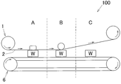
- the produced flux transfer sheet 1 is used in the manufacturing process of an aluminum member as shown in FIG.
- the manufacturing process 100 is provided with a belt conveyor 6 and the like for placing an aluminum member W (hereinafter referred to as “work W”) and sending it downstream.
- work W an aluminum member W
- a flux transfer sheet 1 wound in a roll shape is arranged, and the roll-shaped flux transfer sheet 1 is unwound and sent toward the downstream side, and the unrolled flux transfer is performed.
- the sheet 1 is configured to be wound up again.
- the flux transfer sheet 1 is set so that the surface of the flux layer 2 faces the mounting surface of the belt conveyor 6 when being unwound and fed downstream.
- the manufacturing process 100 includes, for example, three processes, and the unwound flux transfer sheet 1 is first sent to the crimping process A.
- the flux transfer sheet 1 is applied to the surface of the workpiece W, and the flux layer 2 of the flux transfer sheet 1 is brought into close contact with the part to be brazed on the surface of the workpiece W.
- the flux transfer sheet 1 As a method of bringing the flux transfer sheet 1 into close contact with the surface of the workpiece W, the flux transfer sheet 1 is applied to the surface of the workpiece W and pressed with a press or the like, or placed on the surface of the workpiece W placed in a vacuum chamber or the like. In a state where the flux transfer sheet 1 is applied, a method such as reducing the pressure using a vacuum pump or the like is used.
- the flux transfer sheet 1 is made of a flexible material, even if the surface of the workpiece W has irregularities, it can be easily brought into close contact with the shape of the surface of the workpiece W if there are some irregularities. it can.
- the upper surface of the workpiece W placed on the belt conveyor 6 is set to a height at which the flux transfer sheet 1 sent downstream can be easily crimped.
- the flux layer 2 that is in close contact with the workpiece W is pressed or heated to transfer the flux layer 2 to the surface of the workpiece W.
- the flux layer 2 in close contact with the surface of the workpiece W is transferred using a roll laminator or the like.
- the flux layer 2 may be transferred to the surface of the workpiece W using a vacuum laminator device.
- the flux layer 2 is transferred to the surface of the workpiece W by a method of pressing a balloon made of a thermoplastic resin, a method using a pressure such as wind pressure or water pressure, or the like.
- Heating methods include contact-type heating in which a hot roll or a pre-heated pressurizing mold is brought into contact with the workpiece W for heating, and non-contact type heating in which heating is performed without contacting the workpiece W, such as an infrared heater or hot air heater. Etc. are used.
- work W may be heated simultaneously at the time of pressurization, and the workpiece
- the workpiece W and the flux transfer sheet 1 are sent to the downstream side, and the flux transfer sheet 1 that is in close contact with the workpiece W is peeled off from the surface of the workpiece W.
- the aluminum member W to which the flux is attached in this way is subjected to a brazing process.
- brazing material is melted by heating at least a portion where the brazing material is adhered to about 450 ° C. to 600 ° C. under a nitrogen gas atmosphere condition.
- the aluminum members W are joined together.
- the flux layer 2 is transferred onto the surface of the metal member W, and the flux layer 2 is transferred. Since the brazed metal member W is assembled and brazed, a small amount of flux can be uniformly adhered to the surface of the metal member W, and the time of the drying process becomes unnecessary, so Manufacturing time can be shortened.
- the flux can be attached only to the part to be brazed of the metal member W, that is, only the necessary part of the surface of the transfer sheet 1 and the metal member W, there is no waste in the material flux, Since the masking work for the part where the flux does not need to be attached becomes unnecessary, the work load can be reduced.
- the metal member W described above is an aluminum member, a small amount of flux can be uniformly attached to the surface of the aluminum member W even though the flux has almost no adhesion with aluminum, and the drying step The time required for the production of the aluminum member can be shortened.
- the weak release film layer 3 is provided between the flux layer 2 and the base film layer 4, and the strong release film layer 5 is provided on the surface of the base film layer 4 opposite to the release film layer.
- it may be a configuration in which both the release film layers are not provided, or may be a configuration in which only one of the release films is provided.
- the brazing method using a non-corrosive flux such as a non-corrosive fluoride flux has been described as an example, but the flux transfer sheet of the present invention in which the flux layer 2 containing the flux is laminated on the base film. If 1 can be applied, the brazing method and the type of flux are not particularly limited.
- the resin binder to be mixed with the flux is not particularly limited in its type, and an applicable type of resin binder may be adopted.
- the base film layer 4 on which the flux is laminated is also preferably made of a flexible material that can be rolled and unrolled from the viewpoint of being compactly portable.
- the present invention is not particularly limited to this.
- the metal member to which the flux is transferred has been described as an aluminum member, the flux transfer sheet 1, the flux attaching method and the brazing method of the present invention can be applied as long as the metal is brazed by attaching the flux. .
- the flux transfer sheet 1 of the present invention includes the sheet-like base film layer 4 and the flux layer 2 made of the flux and the resin binder laminated on the base film layer 4, and is made of metal. Since the flux layer 2 is transferred to the surface of the member W, the flux layer 2 is transferred to the surface of the metal member W using a transfer sheet in which the flux layer 2 made of a flux and a resin binder is laminated on the base film layer 4. Therefore, unlike the case where a solution such as a paint is applied, it is easy to uniformly apply a small amount of flux to the surface of the metal member W, and the time required for the drying process is not required. Can be shortened.
- the flux can be attached only to the necessary places on the surface of the transfer sheet and the metal member, and the work load is reduced because the masking work for the places where the flux does not need to be attached is reduced. Since the flux can be easily adhered simply by transferring it in close contact with the surface, it is optimal for automation.
- the coating process and the drying process of the aluminum member W are integrated in the manufacturing process of the flux transfer sheet 1, so that the location where a large amount of solvent is used is localized. It can be.
- the processing device for preventing air pollution can be handled locally in the manufacturing process of the Lux transfer sheet 1, and a large amount of solvent can be used at the manufacturing site where the aluminum member W to be brazed is assembled. Since there is no need to use it, and no explosion-proof measures associated with the use of processing equipment for preventing air pollution and the use of organic solvents are required, the work efficiency at the manufacturing site of the aluminum member W can be improved and costs can be reduced. Safety can be improved.
- the effect by the flux transfer sheet 1 of this invention mentioned above can also acquire the same effect by the flux adhesion method and brazing method using the flux transfer sheet 1.
- the flux transfer sheet 1 in which the flux layer 2 is laminated on the base film layer 4 is described for brazing.
- the coating layer 12 containing the flux and the resin binder is laminated on the base film layer 15.
- the brazing material transfer sheet 11 may be used for brazing.
- brazing material transfer sheet 11 of the present invention will be described with reference to the drawings.
- FIG. 4 is a schematic configuration diagram of the brazing material transfer sheet 11
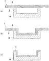
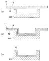
- FIGS. 5 and 6 are explanatory diagrams of how to use the brazing material transfer sheet 11.
- the brazing material transfer sheet 11 of the present invention is for easily attaching a brazing material and a flux to the surface of a metal member, particularly an aluminum member.
- brazing is performed by attaching a brazing material, a flux or the like having a melting point lower than that of the aluminum member to the surface of the aluminum member will be described as an example.
- the brazing material transfer sheet 11 includes a sheet-like base film layer 14 and a coating layer 12 laminated on the base film layer 14.
- a commercially available film such as polyethylene terephthalate (PET), polypropylene (PP), and vinyl chloride (PVC) can be applied, and resistance to solvents used during production and heat resistance during drying. Are used.
- PET polyethylene terephthalate
- PP polypropylene
- PVC vinyl chloride
- the coating layer 12 is formed from a material containing a powdered or particulate brazing material, a powdered or particulate flux, and a resin binder.
- the brazing material is powdered or particulate, and is mixed within a range of 20% to 95% by weight with respect to 100% by weight of the mixed powder in which the brazing material and the flux are mixed.
- brazing material for example, Al—Si is preferably used, but a metal that has a lower melting point than aluminum and forms a eutectic alloy with aluminum at the time of brazing, such as Si, Zn, Cu, and Ge, is used.
- a metal that has a lower melting point than aluminum and forms a eutectic alloy with aluminum at the time of brazing such as Si, Zn, Cu, and Ge.
- An alloy of aluminum and a metal that forms a eutectic alloy with aluminum at the time of brazing may be used, and it is a brazable metal that is powdered or particulate. Any metal that can be mixed with the flux is not particularly limited.
- the flux is made into powder or particles and mixed within the range of 5 to 80% by weight with respect to 100% by weight of the mixed powder of the brazing filler metal and the flux.
- the flux includes a KF.AlF 3 eutectic composition or a complex mixture having a composition range close to this, complex compounds such as KAlF 4 , K 2 AlF 5 , K 3 AlF 6 , ZnKF 3 , CsF, RbF, LiF, Non-corrosive fluoride fluxes such as NaF and Ca 2 F are used.
- complex compounds such as KAlF 4 , K 2 AlF 5 , K 3 AlF 6 , ZnKF 3 , CsF, RbF, LiF
- Non-corrosive fluoride fluxes such as NaF and Ca 2 F are used.
- the resin binder examples include acrylic resins such as polymers of acrylic acid or methacrylic acid and esters thereof, or copolymers of two or more of these, polyalkylene oxides, alkyd resins, alkyd resins and butyl resins ( Or a mixture of petroleum resins).
- acrylic resins such as polymers of acrylic acid or methacrylic acid and esters thereof, or copolymers of two or more of these, polyalkylene oxides, alkyd resins, alkyd resins and butyl resins ( Or a mixture of petroleum resins).
- the resin binder is added to the mixed powder in the range of 1 to 30% by weight, preferably 10% by weight, with respect to 100% by weight of the mixed powder in which the brazing filler metal and the flux are mixed.
- the brazing material transfer sheet 11 is subjected to release treatment on the side opposite to the coating layer 12 and the second release film layer 13 (under the base film layer 14 shown in FIG. 4) with the base film layer 14 interposed therebetween.
- a first release film layer 15 made of a mold film is provided.
- the 2nd release film layer 13 which consists of a release film by which the release process was carried out is provided between the film layer 12 and the base film layer 14, and when transferring the film layer 12 to the aluminum member surface
- the coating layer 12 is configured to be easily peeled off from the base film layer 14.
- a film having a lower release property than the first release film layer 15 is used.
- the second release film layer 13 between the coating layer 12 and the base film layer 14 is referred to as “weak release film layer 13”, and the first release film layer 15 is referred to as “strong release film layer 15”. Also called.
- release film used in the weak release film layer 13 and the strong release film layer 15 known ones such as polyethylene terephthalate-based, polypropylene-based and other stripped films can be used.
- the brazing material transfer sheet 11 Since the first release film layer 15 (strong release film layer 15) is provided on the opposite side of the film layer 12 with the base film layer 14 interposed therebetween, the brazing material transfer sheet 11 is used in a state of being wound in a roll shape. In this case, since the outermost coating layer 12 comes into contact with the first release film layer 15 (strong release film layer 15), the brazing material transfer sheet 11 is unwound. Even if it adheres to the 1st release film layer 15 which the surface of the membrane
- the second release film layer 13 is provided between the coating layer 12 and the base film layer 14, when the coating layer 12 is transferred to the metal member and the brazing material transfer sheet 11 is peeled off, the coating layer 12.
- the film layer 12 can be transferred onto the surface of the metal member without being peeled off and remaining on the brazing material transfer sheet 11.
- the brazing material transfer sheet 11 is generated by the following method.
- a powder or particulate flux is mixed in the same manner as a powder or particulate brazing material to produce a mixed powder, and further, the mixture is obtained by mixing the obtained mixed powder and a resin binder, ie, coating. Obtain a liquid.
- solvents can also be used.
- an organic solvent that dissolves the acrylic resin can be used, and water is also used depending on the composition of the resin binder.
- alcohols such as methanol, ethanol and isopropyl alcohol, esters such as ethyl acetate and butyl acetate, ethers such as ethylene glycol, diethylene glycol and propylene glycol, or acetates can be applied as the organic solvent. .
- additives may be mixed to adjust the performance of the coating liquid or improve the performance
- various additives such as general defoaming materials, leveling agents, and surface conditioning agents may be mixed. it can.
- the coating solution thus obtained is applied so as to uniformly adhere to the base film layer 14, and the weak release film layer 13 on one side and the strong release type on the side without the weak release film layer 13 are applied. It is applied so that the coating liquid uniformly adheres to the weakly release film layer 13 of the base film layer 14 provided with the film layer 15.
- the flux coating amount in the coated coating solution is adjusted to be, for example, 1 g / m 2 to 30 g / m 2, and preferably the flux coating amount is 3 g / m 2 to 10 g / m 2. It is adjusted to be m 2 .
- a coating method using a known coating apparatus such as a roll coater, a gravure coater, or a die coater can be used.
- the coating film layer 12 is formed on the base film layer 14 by drying the base film layer 14 to which the coating liquid has been applied.
- the thickness of the base film layer used is preferably 9 ⁇ m to 30 ⁇ m, for example.
- a drying apparatus which dries the base film layer 14 to which the coating liquid was adhered
- a well-known drying apparatus can be used suitably, such as heat-drying the base film layer 14 with a heating furnace etc. It is preferable to employ a drying apparatus that can dry the brazing material transfer sheet 11 continuously in combination with the coating apparatus.
- the coating liquid may be applied to the entire surface of the base film layer 14, and since no material is wasted, a coating layer 12 that matches the shape of the part to be brazed of the aluminum member is formed. It may be applied on the base film layer 14 as described above.
- the brazing material transfer sheet 11 as described above can apply the brazing material and the flux to the aluminum member by the roll-to-roll method, so that the flux can be efficiently applied.
- the aluminum member is brazed by a brazing method using a non-corrosive flux such as a non-corrosive fluoride-based flux under a nitrogen gas atmosphere condition.
- a non-corrosive flux such as a non-corrosive fluoride-based flux under a nitrogen gas atmosphere condition.
- the flux is used in a very small amount (for example, 3 g / m 2 to 10 g / m 2 ), it should be originally mixed with a large amount of resin binder.
- the amount of the binder is too large, the component of the resin binder that does not volatilize is carbonized and causes brazing failure.
- the produced brazing material transfer sheet 11 is used in an aluminum member manufacturing process as shown in FIG.
- the production line 101 is provided with a belt conveyor 16 and the like for placing an aluminum member W1 (hereinafter also referred to as “workpiece W1” or “metal member W1”) and sending it downstream.
- a belt conveyor 16 for placing an aluminum member W1 (hereinafter also referred to as “workpiece W1” or “metal member W1”) and sending it downstream.
- the brazing material transfer sheet 11 wound around the roll R11 is arranged on the most upstream side of the production line 101, and the roll-shaped brazing material transfer sheet 11 is gradually unwound and sent toward the downstream side to be unwound.
- the brazing material transfer sheet 11 is configured to be wound again on a roll R12 provided on the downstream side.
- the brazing material transfer sheet 11 is set so that the surface of the coating layer 12 faces the mounting surface of the belt conveyor 16 when being unwound and fed downstream.
- the production line 101 includes, for example, three processes, and the unrolled brazing material transfer sheet 11 is first sent to the crimping process AA.
- the brazing material transfer sheet 11 is applied to the surface of the workpiece W1, and the coating layer 12 of the brazing material transfer sheet 11 is brought into close contact with the planned brazing site on the surface of the workpiece W1.
- the brazing material transfer sheet 11 As a method of bringing the brazing material transfer sheet 11 into close contact with the surface of the work W1, the brazing material transfer sheet 11 is in contact with the surface of the work W1 and pressed with a press or the like, or the work W1 placed in a vacuum chamber or the like. In a state where the brazing material transfer sheet 11 is applied to the surface, a method of reducing the pressure with a vacuum pump or the like and bringing it into close contact is used.
- the brazing material transfer sheet 11 is made of a flexible material, even if the surface of the workpiece W1 is uneven, it can be easily brought into close contact with the shape of the surface of the workpiece W1 if it is somewhat uneven. Can do.
- the upper surface of the work W1 placed on the belt conveyor 16 is adjusted to a height at which the brazing material transfer sheet 11 sent downstream can be easily crimped.
- the workpiece W1 in a state where the brazing material transfer sheet 11 is in close contact is sent to the transfer process BB.
- the coating layer 12 that is in close contact with the surface of the workpiece W1 is pressed or heated to transfer the coating layer 12 to the surface of the workpiece W1.
- the film layer 12 that is in close contact with the surface of the workpiece W1 is transferred using a roll laminator or the like.
- the film layer 12 may be transferred to the surface of the workpiece W1 using a vacuum laminator device or the like.
- the workpiece W1 is not a flat plate, such as having an uneven surface, in addition to a vacuum laminator device, a method for creating and pressing a pressing mold corresponding to the workpiece W1 with a material such as metal or plastic, rubber, etc.
- the coating layer 12 is transferred to the surface of the workpiece W1 by a method of pressing a balloon made of a thermoplastic resin, a method using a pressure such as wind pressure or water pressure, or the like.
- a heat roll, a pre-heated pressurizing mold or the like is brought into contact with the work W1, and heating is performed.
- Non-contact type heating or the like for heating without contacting W1 is used.
- workpiece W1 may be heated at the same time during pressurization, or the workpiece W1 may be heated after pressurization.
- the workpiece W1 and the brazing material transfer sheet 11 are sent to the downstream side, and the brazing material transfer sheet 11 that is in close contact with the workpiece W1 is peeled off from the surface of the workpiece W1.
- the base film layer 14 When the base film layer 14 is peeled off, only the coating layer 12 transferred in the transfer step BB adheres to the surface of the workpiece W1, and the film other than the coating layer 12 of the brazing material transfer sheet 11 peeled off from the workpiece W1.
- the layers (in this embodiment, the strong release film layer 15, the base film layer 14 and the weak release film layer 13) are sent to the downstream side and wound up again in a roll shape.
- the aluminum member W1 to which the flux is attached in this way is subjected to a brazing process.
- brazing process for example, a brazing method using a non-corrosive flux is used, and the brazing material is melted by heating at least a portion where the brazing material is adhered to about 450 ° C. to 600 ° C. under a nitrogen gas atmosphere condition.
- the aluminum members W1 are joined to each other.
- a transfer sheet (a brazing material) in which a coating layer 12 containing a powdery or particulate brazing material, a powdery or particulate flux and a resin binder as described above is laminated on a sheet-like base film layer 14.
- the transfer sheet (brazing material transfer sheet 11) is brought into close contact with the surface of the metal member W1 to transfer the coating layer 12, and the metal member W1 to which the coating layer 12 is transferred is assembled and brazed. Therefore, it is possible to attach the brazing material and the flux easily without using the brazing sheet simply by bringing the brazing material transfer sheet 11 into close contact with the metal surface and transferring it.
- the adhesion work of the brazing material and the flux can be simplified.
- the manufacturing time of the metal member W1 can be shortened.
- the brazing material and the flux applied to the metal member W1 are dried at a high temperature by forming the brazing material and the flux into a paint and generating the brazing material transfer sheet 11 in which the coating layer 12 is laminated on the base film layer 14 in advance.
- a drying device or the like is not necessary, and the scale of the entire device for manufacturing the metal member W1 can be reduced. Further, there is no possibility that the metal member W1 is deformed due to high temperature drying.
- the masking work at the locations where the brazing material and the flux do not need to be attached becomes unnecessary, thereby reducing the work load.
- the metal member W1 described above is an aluminum member, a small amount of brazing material and flux can be uniformly adhered to the surface of the aluminum member W1 even though the oxide film formed on the aluminum greatly reduces the adhesion. Since it becomes easy and the time of a drying process becomes unnecessary, the manufacturing time of the aluminum member W1 can be shortened.
- the weak release film layer 13 is provided between the coating layer 12 and the base film layer 14, and the strong release film is provided on the surface opposite to the release film layer with the base film layer 14 interposed therebetween. It is preferable that the layer 15 is provided, but the configuration may be such that both the release film layers 13 and 15 are not provided, or only one of the release film layers 13 and 15 is provided. There may be.
- the brazing material Al—Si is used as the brazing material, and a non-corrosive flux such as a non-corrosive fluoride flux is used as the flux.
- the coating layer 12 of the brazing material transfer sheet 11 is powdered.
- the type of the brazing material and the flux is not particularly limited, and of course the brazing method is not particularly limited. .
- coated to the metal member W1 was obtained by mixing the mixed powder and the resin binder with which the powdery or particulate brazing material and the flux were mixed, it is not necessarily mixed powder and resin.
- the binder does not need to be mixed, and the powdery or particulate flux may be mixed after the powdered or particulate brazing material is mixed with the resin binder. As long as the coating liquid can be obtained using the flux.
- the resin binder to be mixed with the brazing filler metal and the flux is not particularly limited and used, and an applicable type of resin binder may be adopted.
- the base film layer 14 on which the coating layer 12 is laminated is also made of a flexible material that can be rolled and unrolled from the viewpoint of being compactly portable. Is preferable, but not particularly limited thereto.
- the metal member W1 to which the flux is transferred has been described as an aluminum member.
- the brazing material transfer sheet 11 of the present invention can be used as long as the brazing material is powdery or particulate and can be brazed by attaching the flux. Is applicable.
- the brazing material transfer sheet 11 of the present invention includes the sheet-like base film layer 14, the powdery or particulate brazing material, the powdery or particulate flux, and the resin binder. And the coating layer 12 laminated on the material film layer 14, and the coating layer 12 is transferred onto the surface of the metal member W1, so that the brazing material transfer sheet 11 is brought into close contact with the surface of the metal member W1. Since the brazing material can be easily adhered and the flux can be adhered without using a brazing sheet, since the structure is optimal for automation, the soldering material and the flux can be easily adhered. can do.
- the metal member W1 unlike the case where a solution such as a paint is applied to the metal member W1, it is easy to uniformly apply a small amount of brazing material and flux to the surface of the metal member W1, and the time for the drying process is not required. The manufacturing time of the metal member W1 can be shortened.
- the brazing material and the flux applied to the metal member W1 are dried at a high temperature by forming the brazing material and the flux into a paint and generating the brazing material transfer sheet 11 in which the coating layer 12 is laminated on the base film layer 14 in advance.
- a drying device or the like is not required, and the scale of the entire apparatus for manufacturing the metal member W1 can be reduced. Further, there is no possibility that the metal member W1 is deformed due to high temperature drying.
- the masking work at the locations where the brazing material and the flux do not need to be attached becomes unnecessary, thereby reducing the work load.
- the VOC processing apparatus can be handled locally in the manufacturing process of the brazing material transfer sheet 11, and an organic solvent is used at the manufacturing site where the aluminum member W1 for brazing is assembled. Eliminates the need for countermeasures associated with the use of VOC treatment equipment and organic solvents, thereby improving work efficiency at the manufacturing site of the metal member W1 and reducing costs, as well as improving safety. Can do.
- the effect by the brazing material transfer sheet 11 of the present invention described above can be obtained by the brazing material adhesion method and the brazing method using the brazing material transfer sheet 11.
- the flux transfer sheet 120 in which the flux layer 121 is laminated on the base film layer 122 may be brazed using the brazing sheet with flux 110 that is bonded to the brazing sheet 130.
- brazing sheet with flux 110 of the present invention will be described with reference to the drawings.
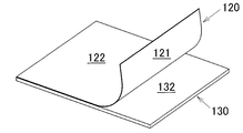
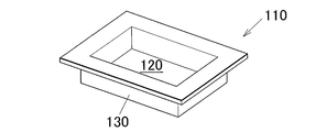
- FIG. 7 is a schematic configuration diagram of the brazing sheet 110 with flux
- FIGS. 8 to 10 are explanatory diagrams for explaining a method of manufacturing the brazing sheet 110 with flux
- FIGS. 11 to 13 are methods of processing the brazing sheet 110 with flux.
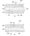
- FIG. 14 is a schematic configuration diagram of another embodiment of the brazing sheet with flux 110.
- the brazing sheet 110 with flux of the present invention includes a brazing sheet 130 formed by cladding a brazing material 132 on one or both sides of a core 131, and a flux layer laminated on the brazing sheet 130. 121 and a sheet-like base film layer 122 laminated on the flux layer 121.
- the brazing sheet 130 is formed by cladding a brazing material 132 having a melting point lower than that of the core material 131 on a core material 131 made of a metal material.
- the brazing sheet 130 made of aluminum alloy is produced as follows.
- the core 131 member and the brazing material 132 that have been subjected to melting, casting, homogenization heat treatment, and the like are overlaid and clad by hot rolling.
- the brazing sheet 130 was obtained by subjecting these clad materials to rough annealing, cold rolling, intermediate annealing, and the like.
- the obtained brazing sheet 130 is formed into a flat plate having an arbitrary thickness and a clad rate depending on the application, and a brazing material 132 is clad on one side or both sides of the core material 131.
- the thickness of the brazing sheet is 0.5 mm to 10.0 mm and the clad rate is 5% to 15%, but is not limited thereto.
- heating conditions and atmosphere in brazing are not particularly limited.
- the flux transfer sheet 120 is bonded to the surface of the brazing sheet 130 obtained as described above where the brazing material 132 is clad.
- the flux transfer sheet 120 includes a sheet-like base film layer 122 and a flux layer 121 made of a flux and a resin binder.
- the flux transfer sheet 120 is generated by the following method.
- Flux A resin binder is mixed at a ratio of 99: 1 to 50:50 (weight ratio) to obtain a flux solution that is a mixture in which the flux is dissolved.
- the flux includes a KF.AlF 3 eutectic composition or a complex mixture having a composition range close to this, complex compounds such as KAlF 4 , K 2 AlF 5 , K 3 AlF 6 , ZnKF 3 , CsF, RbF, LiF, Non-corrosive fluoride fluxes such as NaF and Ca 2 F are used.
- complex compounds such as KAlF 4 , K 2 AlF 5 , K 3 AlF 6 , ZnKF 3 , CsF, RbF, LiF
- Non-corrosive fluoride fluxes such as NaF and Ca 2 F are used.
- the resin binder includes acrylic resins such as acrylic acid or methacrylic acid and their esters, or copolymers of two or more of these, polyalkylene oxide, alkyd resin, alkyd resin and butyl. A mixture of resin (or petroleum resin) is used.
- the total amount of the flux and the resin binder is 100% by weight, and it is preferable to blend 1% by weight to 50% by weight of the resin binder, more preferably 5% to 15% by weight of a resin binder is blended.
- the flux transfer sheet 120 can be produced satisfactorily by adjusting the viscosity of the flux solution using a solvent.
- the solvent used for example, an organic solvent that dissolves acrylic resin can be used, and water is also used depending on the composition of the resin binder.
- alcohols such as methanol, ethanol and isopropyl alcohol, esters such as ethyl acetate and butyl acetate, ethers such as ethylene glycol, diethylene glycol and propylene glycol, or acetates can be applied as the organic solvent. .
- additives may be mixed to adjust the performance of the coating liquid or improve the performance
- various additives such as general defoaming materials, leveling agents, and surface conditioning agents may be mixed. it can.
- Coating amount (in the brazing sheet depending on the brazing material amount of commercially available brazing sheet) flux is adjusted so as to 1g / m 2 ⁇ 30g / m 2, the flux is 3g / m 2 ⁇ 10g / It is preferable that the coating amount is adjusted so as to be m 2 .
- a coating method using a known coating apparatus such as a roll coater, a gravure coater, or a die coater can be used.
- the base film layer 122 for example, commercially available films such as polyethylene terephthalate (PET), polypropylene (PP), and vinyl chloride (PVC) can be applied, and resistance to solvents used during production and heat resistance during drying. Are used.
- PET polyethylene terephthalate
- PP polypropylene
- PVC vinyl chloride
- a film having a thickness of 9 ⁇ m to 30 ⁇ m is preferably used.
- the material of the base film layer 122 is preferably a flexible material that can be rolled and unrolled from the viewpoint of being compactly portable.
- the invention is not particularly limited to this.
- the flux transfer sheet 120 forms the flux layer 121 on the base film layer 122 by drying the base film layer 122 to which the flux solution is applied and adhered.
- a drying apparatus for drying the base film layer 122 to which the flux solution is adhered a known drying apparatus can be used as appropriate, such as heating and drying the base film layer 122 in a heating furnace, etc., which is combined with a coating apparatus. It is preferable to employ one that can continuously dry the flux transfer sheet 120.
- the flux solution may be applied to the entire surface of the base film layer 122, and since there is no waste of material, the flux solution is applied so as to match the shape of the part to be brazed of the aluminum member. 121 may be formed.
- the VOC volatile organic compound
- the brazing sheet 130 is used. Since the coating process and the drying process are combined in the manufacturing process of the flux transfer sheet 120, the location where the solvent is used can be made local.
- the processing apparatus for preventing air pollution can be handled locally in the manufacturing process of the flux transfer sheet 120, and the solvent can be used at the manufacturing site where the brazing sheet with flux 110 for brazing is assembled. Since it is no longer necessary to use it and no measures are required due to the use of VOC treatment equipment or organic solvents, it is possible to improve the work efficiency at the production site of metal parts, reduce costs, and increase safety. be able to.
- a release film layer made of a release film that has been subjected to a release treatment may be provided between the flux layer 121 and the base film layer 122 described above.
- a release film layer is provided on one surface of the base film layer 122, and the flux solution is applied on the release film layer so as to adhere uniformly.
- the flux layer 121 is easily peeled from the base film layer 122 when transferred to the surface of the brazing sheet 130.
- release film used in the release film layer known ones such as polyethylene terephthalate-based, polypropylene-based and other peeled films can be used.
- the flux layer 121 and the base film layer 122 can be attached to the surface of the brazing sheet 130 by a roll-to-roll method, so that the flux can be efficiently applied. it can.
- the brazing sheet with flux 110 is obtained through the pasting process in which the brazing sheet 130 and the flux transfer sheet 120 obtained as described above are pasted together.
- the brazing sheet 130 wound in a roll shape on the roll R101 is unwound, and similarly downstream with the flux transfer sheet 120 unrolled from the roll shape on the roll R102.
- the laminated brazing sheet 130 and the flux transfer sheet 120 are pasted together by the pressure-bonding roll M, they are rewound into a roll shape by the roll R103.
- the crimping roll may heat the brazing sheet 130 simultaneously with pressurization, or may be vacuum-bonded as necessary.
- the surface material, pressure, temperature, and the like of the pressure-bonding roll are appropriately selected by an optimal combination according to the types of the brazing sheet 130 and the flux transfer sheet 120.
- the brazing sheet 130 can be bonded with a pressure roll by the same method.
- the flux transfer sheet 120 in which the flux layer 121 is laminated on the base film layer 122 is bonded to the brazing sheet 130, the flux transfer sheet 120 is bonded to the brazing sheet 130, that is, the sheet.
- the flux can be attached to the core 131 by a simple operation of simply bonding the members 120 and 130 together.
- the flux can be attached only to the necessary portions on the surfaces of the flux transfer sheet 120 and the brazing sheet 130, and the masking work for the portions where the flux does not need to be attached becomes unnecessary, thereby reducing the work load.
- the generated brazing sheet with flux 110 is subjected to machining including processing and molding in a state where the flux transfer sheet 120 and the brazing sheet 130 are bonded together.
- machining including processing and molding in a state where the flux transfer sheet 120 and the brazing sheet 130 are bonded together.
- the mechanical processing applied to the brazing sheet with flux 110 in the present invention with the flux transfer sheet 120 attached thereto includes processing such as pressing, cutting, punching, and bending.
- the brazing sheet 110 with flux is disposed so as to be sandwiched between the upper press mold P2 and the lower press mold P3 of the press machine P, and the press upper mold P2 is pressed by the press P1 so as to be pressed into the lower press mold P3. Press.
- the brazing sheet with flux 110 is placed and pressed such that the base film layer 122 faces the upper press mold P2 side.
- the base film layer 122 laminated on the inner surface (upper surface shown in FIG. 12) of the press-molded body thus obtained is peeled from the press-molded body so that the flux layer 121 is exposed.
- the base film layer 122 is peeled off after machining.
- the flux layer 121 is easily transferred to the surface of the brazing sheet 130.
- the press-molded bodies in a state where the base film layer 122 is peeled and the flux layer 121 attached to the surface of the brazing sheet 130 is exposed are combined and subjected to a brazing process.
- the brazing step for example, a brazing method using a non-corrosive flux is used, and the brazing material 132 is heated by heating at least a portion where the brazing material 132 is adhered to about 450 ° C. to 600 ° C. under a nitrogen gas atmosphere condition. And the press-molded bodies are joined to each other.
- the flux layer 121 containing the flux and the resin binder and the sheet-like base film layer 122 are sequentially laminated on the brazing sheet 130 obtained by cladding the brazing material 132 on the core material 131 made of a metal material. If the brazing sheet 130 is machined in a state where the flux layer 121 and the base film layer 122 are laminated, the base film layer 122 is peeled from the brazing sheet 130.
- the brazing sheet with flux 110 protected by the base film layer 122 can be subjected to machining such as press working, and when the processing is performed, the base film layer 122 laminated on the outermost side. Can function as a lubricant, reducing the amount of oil and other lubricants used. It is possible to reduce the cost.
- the base film layer 122 is laminated on the outermost side, and the base film layer 122 functions as a protective layer that protects the flux layer 121 and below. It is possible to prevent the flux from falling off due to rubbing or the like.
- the core material 131 of the brazing sheet 110 with flux described above is aluminum, the required amount of flux can be adhered to the surface of the aluminum even though the aluminum has almost no adhesion to the flux.
- the flux transfer sheet 120 when used, unlike a case where a solution such as a paint is directly applied to aluminum, it becomes easy to uniformly attach a small amount of flux to the surface of the aluminum, and the time for the drying process is reduced. This eliminates the need for the manufacturing time of the aluminum member.
- the flux transfer sheet 120 described above has been described so that a release film (hereinafter referred to as “weak release film layer”) is provided between the flux layer 121 and the base film layer 122. May be provided with a release film (hereinafter referred to as “strongly release film layer”) on the surface opposite to the weak release film with the base film layer 122 interposed therebetween.
- a release film layer made of a release film that has been subjected to a release treatment may be provided on both surfaces of the material film layer 122.
- the weak release film layer may be a film having a lower release property than the strong release film layer.
- the flux transfer sheet 120 When used in a rolled state, the flux transfer sheet 120 is laminated, but the outermost flux layer 121 comes into contact with the strong release film layer. When the sheet 120 is unrolled, the weak release film is peeled off from the flux layer 121, and the flux layer 121 is peeled off without sticking to the strong release film layer with which the surface of the flux layer 121 contacts. Can do.
- a weak release film layer is provided between the flux layer 121 and the base film layer 122, and a strong release film layer is provided on the surface opposite to the weak release film layer with the base film layer 122 interposed therebetween.
- a strong release film layer is provided on the surface opposite to the weak release film layer with the base film layer 122 interposed therebetween.
- it may be configured such that neither of the release film layers is provided, or may be configured such that only one of the release films is provided.
- the flux layer 121 and the base film layer 122 are mainly laminated on the surface of the brazing sheet 130 clad with the brazing material 132 on one side of the core material 131.
- the flux transfer sheet 120 is configured to be bonded to both surfaces of the brazing sheet 130 in which the brazing material 132 is clad on both surfaces of the core material 131. Also good.
- the flux layer 121 and the base film layer 122 are laminated on the surface of the brazing sheet 130 clad with the brazing material 132 on one side, and the flux layer 121 is laminated.
- a multilayer structure may be employed such that a sacrificial layer in which a metal such as Zn is laminated is provided on the opposite surface on which the base film layer 122 is laminated.
- the flux transfer sheet 120 is attached to the brazing sheet 130 so that the flux adheres to the brazing sheet 130.
- the flux transfer sheet 120 is not used, and the surface of the brazing sheet 130 is directly used.
- a flux solution may be applied, and the base film layer 122 may be laminated on the flux layer 121 thus laminated.
- the brazing method using a non-corrosive flux such as a non-corrosive fluoride-based flux has been described as an example.
- the flux transfer sheet 120 in which the flux layer 121 containing the flux is laminated on the base film is a metal material.
- the brazing sheet with flux 110 of the present invention formed by laminating a brazing sheet 130 clad with a brazing material 132 on a core material 131 made of the above is applicable, the type of flux is not particularly limited.
- the type of resin binder mixed with the flux is not particularly limited, and an applicable type of resin binder may be employed.
- the core material 131 and the brazing material 132 of the brazing sheet 130 have been described as aluminum and an aluminum alloy, respectively, but any metal material that can be brazed using the flux transfer sheet 120 will be described.
- the manufacturing method of the brazing sheet 110, the brazing sheet 110 with a flux, and the manufacturing method of a metal member are applicable.
- the brazing sheet with flux 110 of the present invention includes the brazing sheet 130 formed by clad the brazing material 132 on one side or both sides of the core 131 made of a metal material, the flux and the resin binder.
- the brazing sheet 130 includes a flux layer 121 that is laminated on the surface clad with the brazing material 132 and a sheet-like base film layer 122 that is laminated on the flux layer 121. Until the base film layer 122 is laminated on the outermost side, and the base film layer 122 functions as a protective layer that protects the flux layer 121 and below. It is possible to prevent flux from falling off due to prevention and rubbing. That.
- the core material 131 protected by the base film layer 122 can be subjected to machining such as press working, and when the machining process is performed, the base film layer 122 laminated on the outermost side is formed. Since it functions as a lubricant, the amount of lubricant such as oil used can be reduced, and the manufacturing cost can be reduced.
- the effect by the brazing sheet 110 with a flux mentioned above can also acquire the same effect by the manufacturing method of the brazing sheet 110 with a flux of this invention, and the manufacturing method of a metal member.
- the present invention is suitably used for easily attaching a flux and / or brazing material to the surface of a metal member.
Landscapes
- Engineering & Computer Science (AREA)
- Mechanical Engineering (AREA)
- Chemical & Material Sciences (AREA)
- Materials Engineering (AREA)
- Laminated Bodies (AREA)
Abstract
金属、特に、アルミニウムにフラックスを付着させるためのフラックス転写シート、フラックス付着方法及びろう付け方法を提供する。 フラックス転写シート1は、シート状の基材フィルム層4と、前記基材フィルム層4上に積層されるフラックス及び樹脂バインダーからなるフラックス層2と、を備え、金属部材Wの表面に前記フラックス層2を転写する。
Description
本発明は、金属、特に、アルミニウムにフラックスを付着させるためのフラックス転写シート、フラックス付着方法及びろう付け方法に関する。
従来、アルミニウムなどの金属部材をろう付けする際に、金属部材の表面にフラックスを付着させてろう付けが行われている。
アルミニウムにろう付けするためのフラックスは、アルミニウムとの密着力が殆どなく、フラックスの脱落によりろう付け不良が生じるため、フラックスと樹脂バインダーなどを混合した塗料を生成し、アルミニウム部材表面に当該塗料を塗布してフラックス脱落を防止することが提案されている(例えば、特許文献1)。
しかしながら、ろう付けを確実なものとするためには、アルミニウム部材表面にフラックスを均一に付着させる必要があるが、特許文献1に示すような塗料を塗布する場合には、アルミニウム部材表面に付着した塗料が部分的に溜まるなどして、アルミニウム部材表面にフラックスを均一に付着させることは困難であった。
また、アルミニウム部材表面に付着させた塗料を乾燥させるためには、乾燥工程に時間を要する上、アルミニウム部材を短時間で乾燥させるには乾燥装置などが必要となり、その場合には、アルミニウム部材全体を収めることのできる大きさの装置が必要となるため、製造装置全体の規模が大きくなってしまうという問題があった。
更に、アルミニウム部材を乾燥させる際の温度が高過ぎると、アルミニウム部材に歪みなどの変形が生じるという虞があった。
本発明は、上述した技術背景に鑑み、金属、特に、アルミニウムにフラックスを容易に付着させることができるフラックス付着方法及びフラックス転写シートの提供を目的とする。
即ち、本発明は下記[1]~[18]に記載の構成を有する。
[1] シート状の基材フィルム層と、
前記基材フィルム層上に積層されるフラックス及び樹脂バインダーからなるフラックス層と、
を備え、
金属部材の表面に前記フラックス層を転写することを特徴とするフラックス転写シート。
前記基材フィルム層上に積層されるフラックス及び樹脂バインダーからなるフラックス層と、
を備え、
金属部材の表面に前記フラックス層を転写することを特徴とするフラックス転写シート。
[2] 前記基材フィルム層の前記フラックス層と反対側には、第1離型フィルム層が設けられることを特徴とする前項1に記載のフラックス転写シート。
[3] 前記基材フィルム層と前記フラックス層の間には、第2離型フィルム層が設けられることを特徴とする前項1に記載のフラックス転写シート。
[4] 前記基材フィルム層の前記フラックス層と反対側には、第1離型フィルム層が設けられ、
前記基材フィルム層と前記フラックス層の間には、前記第1離型フィルム層よりも離型性の低い第2離型フィルム層が設けられることを特徴とする前項1に記載のフラックス転写シート。
前記基材フィルム層と前記フラックス層の間には、前記第1離型フィルム層よりも離型性の低い第2離型フィルム層が設けられることを特徴とする前項1に記載のフラックス転写シート。
[5] 前記金属部材が、アルミニウム部材であることを特徴とする前項1~4のいずれかに記載のフラックス転写シート。
[6] 基材フィルム層上にフラックス及び樹脂バインダーからなるフラックス層が積層された転写シートを用いて、
金属部材の表面に前記転写シート上の前記フラックス層を転写することを特徴とするフラックス付着方法。
金属部材の表面に前記転写シート上の前記フラックス層を転写することを特徴とするフラックス付着方法。
[7] 基材フィルム層上にフラックス及び樹脂バインダーからなるフラックス層が積層された転写シートを用いて、
金属部材の表面に前記転写シート上の前記フラックス層の転写がなされ、
前記フラックス層が転写された前記金属部材を組み立ててろう付けがなされることを特徴とするろう付け方法。
金属部材の表面に前記転写シート上の前記フラックス層の転写がなされ、
前記フラックス層が転写された前記金属部材を組み立ててろう付けがなされることを特徴とするろう付け方法。
[8] シート状の基材フィルム層と、
粉末状または粒子状のろう材、粉末状または粒子状のフラックス及び樹脂バインダーを含み、前記基材フィルム層上に積層された皮膜層と、
を備え、
金属部材の表面に前記皮膜層が転写されるように構成されたことを特徴とするろう材転写シート。
粉末状または粒子状のろう材、粉末状または粒子状のフラックス及び樹脂バインダーを含み、前記基材フィルム層上に積層された皮膜層と、
を備え、
金属部材の表面に前記皮膜層が転写されるように構成されたことを特徴とするろう材転写シート。
[9] 前記基材フィルム層を挟んで前記皮膜層と反対側には、第1離型フィルム層が設けられることを特徴とする前項8に記載のろう材転写シート。
[10] 前記基材フィルム層と前記皮膜層との間には、第2離型フィルム層が設けられることを特徴とする前項8に記載のろう材転写シート。
[11] 前記基材フィルム層を挟んで前記皮膜層と反対側には、第1離型フィルム層が設けられ、
前記基材フィルム層と前記皮膜層との間には、前記第1離型フィルム層よりも離型性の低い第2離型フィルム層が設けられることを特徴とする前項8に記載のろう材転写シート。
前記基材フィルム層と前記皮膜層との間には、前記第1離型フィルム層よりも離型性の低い第2離型フィルム層が設けられることを特徴とする前項8に記載のろう材転写シート。
[12] 前記金属部材が、アルミニウム部材であることを特徴とする請求項8~11のいずれかに記載のろう材転写シート。
[13] 粉末状または粒子状のろう材、粉末状または粒子状のフラックス及び樹脂バインダーを含んでなる皮膜層が、シート状の基材フィルム層上に積層された転写シートを用いて、
金属部材の表面に前記転写シートの前記皮膜層を転写することを特徴とするろう材付着方法。
金属部材の表面に前記転写シートの前記皮膜層を転写することを特徴とするろう材付着方法。
[14] 粉末状または粒子状のろう材、粉末状または粒子状のフラックス及び樹脂バインダーを含んでなる皮膜層が、シート状の基材フィルム層上に積層された転写シートを用いて、
金属部材の表面に前記転写シートを密着させて前記皮膜層の転写がなされ、
前記皮膜層が転写された前記金属部材を組み立ててろう付けがなされることを特徴とするろう付け方法。
金属部材の表面に前記転写シートを密着させて前記皮膜層の転写がなされ、
前記皮膜層が転写された前記金属部材を組み立ててろう付けがなされることを特徴とするろう付け方法。
[15] 金属材料からなる芯材の片面、或いは両面にろう材がクラッドされて形成されたブレージングシートと、
フラックス及び樹脂バインダーを含み、前記ブレージングシートの前記ろう材がクラッドされた面に積層されるフラックス層と、
前記フラックス層に積層されるシート状の基材フィルム層と、
を備え、
前記基材フィルム層上に前記フラックス層が積層されてなるフラックス転写シートが、
前記ブレージングシートと貼り合わされてなることを特徴とするフラックス付ブレージングシート。
フラックス及び樹脂バインダーを含み、前記ブレージングシートの前記ろう材がクラッドされた面に積層されるフラックス層と、
前記フラックス層に積層されるシート状の基材フィルム層と、
を備え、
前記基材フィルム層上に前記フラックス層が積層されてなるフラックス転写シートが、
前記ブレージングシートと貼り合わされてなることを特徴とするフラックス付ブレージングシート。
[16] 前記芯材が、アルミニウムであることを特徴とする前項15に記載のフラックス付ブレージングシート。
[17] 金属材料からなる芯材の片面、或いは両面にろう材がクラッドされてブレージングシートが生成され、
前記ブレージングシートの前記ろう材がクラッドされた面に、フラックス及び樹脂バインダーを含むフラックス層が形成され、
前記フラックス層にシート状の基材フィルム層が積層され、
前記基材フィルム層上に前記フラックス層が積層されてなるフラックス転写シートが、
前記ブレージングシートと貼り合わされることを特徴とするフラックス付ブレージングシートの製造方法。
前記ブレージングシートの前記ろう材がクラッドされた面に、フラックス及び樹脂バインダーを含むフラックス層が形成され、
前記フラックス層にシート状の基材フィルム層が積層され、
前記基材フィルム層上に前記フラックス層が積層されてなるフラックス転写シートが、
前記ブレージングシートと貼り合わされることを特徴とするフラックス付ブレージングシートの製造方法。
[18] 金属材料からなる芯材にろう材をクラッドしてなるブレージングシートに、フラックス及び樹脂バインダーを含むフラックス層と、シート状の基材フィルム層とが積層され、前記基材フィルム層上に前記フラックス層が積層されてなるフラックス転写シートが、前記ブレージングシートと貼り合わされてなり、
前記フラックス層及び基材フィルム層が積層された状態のままで前記ブレージングシートの機械加工がなされた後、前記基材フィルム層が前記ブレージングシートから剥離されることを特徴とする金属部材の製造方法。
前記フラックス層及び基材フィルム層が積層された状態のままで前記ブレージングシートの機械加工がなされた後、前記基材フィルム層が前記ブレージングシートから剥離されることを特徴とする金属部材の製造方法。
上記[1]に記載の発明によれば、シート状の基材フィルム層と、基材フィルム層上に積層されるフラックス及び樹脂バインダーからなるフラックス層と、を備え、金属部材の表面にフラックス層を転写するので、塗料などの溶液を金属部材に直接塗布する場合とは異なり、金属部材の表面に少量のフラックスを均一に付着させることが容易になり、乾燥工程の時間が不要となるため金属部材の製造時間を短縮させることができる。
高温で乾燥させる乾燥装置が不要となるので、金属部材を製造する装置全体の規模を縮小させることができ、高温乾燥により金属部材が変形するなどの虞がなくなる。
また、転写シート及び金属部材の表面の必要な箇所のみにフラックスを付着させることができ、フラックスの付着が不要な箇所のマスキング作業が不要となるため作業負担が軽減される上、転写フィルムを金属表面に密着させて転写させるだけで容易にフラックスを付着させることができるので、自動化に最適である。
上記[2]に記載の発明によれば、第1離型フィルム層が、基材フィルム層のフラックス層と反対側に設けられるので、フラックス転写シートがロール状に巻かれた状態で使用される場合に、最も外側に位置するフラックス層は、第1離型フィルム層と接触することになるため、フラックス転写シートが巻き解かれる際などであっても、フラックス層の表面が接触する第1離型フィルム層に張り付いたりすることなくフラックス転写シートを剥離させることができる。
上記[3]に記載の発明によれば、基材フィルム層とフラックス層の間には、第2離型フィルム層が設けられるので、金属部材にフラックス層を転写させるためフラックス転写シートを剥がす際に、フラックス層がうまく剥がれずにフラックス転写シートに残ることなく、フラックス層を金属部材の表面に転写させることができる。
上記[4]に記載の発明によれば、基材フィルム層のフラックス層と反対側に第1離型フィルム層が設けられ、基材フィルム層とフラックス層の間には、第1離型フィルム層よりも離型性の低い第2離型フィルム層が設けられるので、フラックス転写シートがロール状に巻かれた状態で使用される場合に、第1離型フィルム層と接触することになる最も外側に位置するフラックス層が、フラックス転写シートが巻き解かれる際などに、第2離型フィルム層からフラックス層が剥がれて、フラックス層の表面が接触する第1離型フィルム層に張り付くなどすることなくフラックス転写シートを剥離させることができる。
また、フラックス層を金属部材に転写させるためフラックス転写シートを剥がす際には、フラックス層がうまく剥がれずに基材フィルム層側に残ることなく、金属部材の表面に転写させることができる。
上記[5]に記載の発明によれば、金属部材がアルミニウム部材であるので、アルミニウムとの密着力が殆どないフラックスであるにも関わらず、アルミニウム部材の表面に少量のフラックスを均一に付着させることが容易になり、乾燥工程の時間が不要となるためアルミニウム部材の製造時間を短縮させることができる。
上記[6]に記載の発明によれば、基材フィルム層上にフラックス及び樹脂バインダーからなるフラックス層が積層された転写シートを用いて、金属部材の表面に転写シート上のフラックス層を転写させるので、塗料などの溶液を金属部材に直接塗布する場合とは異なり、金属部材の表面にフラックスを均一に付着させることが容易になり、乾燥工程の時間が不要となるため金属部材の製造時間を短縮することができる。
高温で乾燥させる乾燥装置が不要となるので、金属部材を製造する装置全体の規模を縮小させることができ、高温乾燥により金属部材が変形するなどの虞がなくなる。
また、転写シート及び金属部材の表面の必要な箇所のみにフラックスを付着させることができ、フラックスの付着が不要な箇所のマスキング作業が不要となるため作業負担が軽減される上、転写フィルムを金属表面に密着させて転写させるだけで容易にフラックスを付着させることができるので、自動化に最適である。
上記[7]に記載の発明によれば、基材フィルム層上にフラックス及び樹脂バインダーからなるフラックス層が積層された転写シートを用いて、金属部材の表面に転写シート上のフラックス層の転写がなされ、フラックス層が転写された金属部材を組み立ててろう付けがなされるので、金属部材の表面に少量のフラックスを均一に付着させてろう付けすることができ、乾燥工程の時間が不要となるため金属部材の製造時間を短縮することができる。
高温で乾燥させる乾燥装置が不要となるので、金属部材を製造する装置全体の規模を縮小することができ、高温乾燥により金属部材が変形するなどの虞がなくなる。
また、転写シート及び金属部材の表面の必要な箇所のみにフラックスを付着させることができるので材料の無駄がなく、フラックスの付着が不要な箇所のマスキング作業が不要となるため作業負担を軽減することができる。
上記[8]に記載の発明によれば、シート状の基材フィルム層と、粉末状または粒子状のろう材、粉末状または粒子状のフラックス及び樹脂バインダーを含み、基材フィルム層上に積層された皮膜層と、を備え、金属部材の表面に皮膜層が転写されるように構成されるので、ろう材転写シートを金属部材表面に密着させて転写させるだけで、ブレージングシートを用いることなく容易にろう材を付着させると共にフラックスを付着させることができ、自動化に最適な構成であるため、ろう材及びフラックスの付着作業を簡便なものとすることができる。
また、塗料などの溶液を金属部材に直接塗布する場合とは異なり、金属部材の表面に少量のろう材及びフラックスを均一に付着させることが容易になり、乾燥工程の時間が不要となるため金属部材の製造時間を短縮させることができる。
ろう材及びフラックスを塗料化して基材フィルム層に皮膜層を積層したろう材転写シートを事前に生成することによって、金属部材に塗布されたろう材及びフラックスを高温で乾燥させるための乾燥装置などが不要となり、金属部材を製造する装置全体の規模を縮小させることができる上、高温乾燥により金属部材が変形するなどの虞がなくなる。
更に、必要な箇所にのみろう材及びフラックスをろう材転写シートに付着させると、ろう材及びフラックスの付着が不要な箇所のマスキング作業が不要となるため作業負担が軽減される。
上記[9]に記載の発明によれば、基材フィルム層を挟んで皮膜層と反対側には、第1離型フィルム層が設けられるので、ろう材転写シートがロール状に巻かれた状態で使用される場合に、最も外側に位置する皮膜層が第1離型フィルム層と接触することになるため、ろう材転写シートが巻き解かれる際などであっても、皮膜層の表面が接触する第1離型フィルム層に貼り付いたりすることなく剥離させることができる。
上記[10]に記載の発明によれば、基材フィルム層と皮膜層との間には、第2離型フィルム層が設けられるので、金属部材に皮膜層を転写させてろう材転写シートを剥がす際に、皮膜層がうまく剥がれずにろう材転写シートに残ることなく、皮膜層を金属部材の表面に転写させることができる。
上記[11]に記載の発明によれば、基材フィルム層を挟んで皮膜層と反対側には、第1離型フィルム層が設けられ、基材フィルム層と皮膜層との間には、第1離型フィルム層よりも離型性の低い第2離型フィルム層が設けられるので、ろう材転写シートがロール状に巻かれた状態で使用される場合に、最も外側に位置する皮膜層が第1離型フィルム層と接触することになるため、ろう材転写シートが巻き解かれる際などであっても、皮膜層の表面が接触する第1離型フィルム層に貼り付いたりすることなく基材フィルム層のみを剥離させることができる。
また、金属部材に皮膜層を転写させるためろう材転写シートを剥がす際には、皮膜層がうまく剥がれずにろう材転写シートに残ることなく、金属部材の表面に皮膜層を転写させることができる。
上記[12]に記載の発明によれば、金属部材が、アルミニウム部材であるので、アルミニウムに形成された酸化皮膜が密着性を大きく落とすのにも関わらず、アルミニウム部材の表面に少量のろう材及びフラックスを均一に付着させることが容易になり、乾燥工程の時間が不要となるためアルミニウム部材の製造時間を短縮させることができる。
上記[13]に記載の発明によれば、粉末状または粒子状のろう材、粉末状または粒子状のフラックス及び樹脂バインダーを含んでなる皮膜層が、シート状の基材フィルム層上に積層された転写シートを用いて、金属部材の表面に転写シート上の前記皮膜層を転写するので、ろう材転写シートを金属部材表面に密着させて転写させるだけで、ブレージングシートを用いることなく容易にろう材を付着させると共にフラックスを付着させることができ、自動化に最適な構成であるため、ろう材及びフラックスの付着作業を簡便なものとすることができる。
また、塗料などの溶液を金属部材に直接塗布する場合とは異なり、金属部材の表面に少量のろう材及びフラックスを均一に付着させることが容易になり、乾燥工程の時間が不要となるため金属部材の製造時間を短縮させることができる。
ろう材及びフラックスを塗料化して基材フィルム層に皮膜層を積層したろう材転写シートを事前に生成することによって、金属部材に塗布されたろう材及びフラックスを高温で乾燥させるための乾燥装置などが不要となり、金属部材を製造する装置全体の規模を縮小させることができる上、高温乾燥により金属部材が変形するなどの虞がなくなる。
更に、必要な箇所にのみろう材及びフラックスをろう材転写シートに付着させると、ろう材及びフラックスの付着が不要な箇所のマスキング作業が不要となるため作業負担が軽減される。
上記[14]に記載の発明によれば、粉末状または粒子状のろう材、粉末状または粒子状のフラックス及び樹脂バインダーを含んでなる皮膜層が、シート状の基材フィルム層上に積層された転写シートを用いて、金属部材の表面に前記転写シートを密着させて前記皮膜層の転写がなされ、皮膜層が転写された金属部材を組み立ててろう付けがなされるので、ろう材転写シートを金属部材表面に密着させて転写させるだけで、ブレージングシートを用いることなく容易にろう材を付着させると共にフラックスを付着させることができ、自動化に最適な構成であるため、ろう材及びフラックスの付着作業を簡便なものとすることができる。
また、塗料などの溶液を金属部材に直接塗布する場合とは異なり、金属部材の表面に少量のろう材及びフラックスを均一に付着させることが容易になり、乾燥工程の時間が不要となるため金属部材の製造時間を短縮させることができる。
ろう材及びフラックスを塗料化して基材フィルム層に皮膜層を積層したろう材転写シートを事前に生成することによって、金属部材に塗布されたろう材及びフラックスを高温で乾燥させるための乾燥装置などが不要となり、金属部材を製造する装置全体の規模を縮小させることができる上、高温乾燥により金属部材が変形するなどの虞がなくなる。
更に、必要な箇所にのみろう材及びフラックスをろう材転写シートに付着させると、ろう材及びフラックスの付着が不要な箇所のマスキング作業が不要となるため作業負担が軽減される。
上記[15]に記載の発明によれば、金属材料からなる芯材の片面、或いは両面にろう材がクラッドされて形成されたブレージングシートと、フラックス及び樹脂バインダーを含み、ブレージングシートのろう材がクラッドされた面に積層されるフラックス層と、フラックス層に積層されるシート状の基材フィルム層と、を備え、基材フィルム層上にフラックス層が積層されてなるフラックス転写シートが、ブレージングシートと貼り合わされてなるので、剥離されるまでは基材フィルム層が最も外側に積層された状態となり、基材フィルム層がフラックス層以下を保護する保護層として機能するため、フラックス層への汚れの付着や異物の混入の防止、また擦れるなどすることによるフラックスの脱落を防止することができる。
また、基材フィルム層で保護した状態のブレージングシートに切断、折り曲げ、打ち抜き、プレス加工などの機械加工を行うことができ、機械加工処理がなされる場合には、最も外側に積層された基材フィルム層が潤滑剤として機能するので、オイルなどの潤滑剤の使用量が削減され、製造コストを低減させることができる。
フラックス転写シートをブレージングシートに貼り合わせる、即ちシート同士を貼り合わせるだけの簡単な作業で、ブレージングシートにフラックスを付着させることができる。
また、フラックス転写シート及びブレージングシートの表面の必要な箇所のみにフラックスを付着させることができ、フラックスの付着が不要な箇所のマスキング作業が不要となるため作業負担が軽減される。
上記[16]に記載の発明によれば、芯材が、アルミニウムであるので、フラックスとの密着力が殆どないアルミニウムであるにも関わらず、アルミニウムの表面に必要量のフラックスを付着させることができる。
特に、フラックス転写シートが用いられる場合には、塗料などの溶液をアルミニウムに直接塗布する場合とは異なり、アルミニウムの表面に少量のフラックスを均一に付着させることが容易になり、乾燥工程の時間が不要となるためアルミニウム部材の製造時間を短縮させることができる。
上記[17]に記載の発明によれば、金属材料からなる芯材の片面、或いは両面にろう材がクラッドされてブレージングシートが生成され、ブレージングシートのろう材がクラッドされた面に、フラックス及び樹脂バインダーを含むフラックス層が形成された基材フィルム層が積層され、基材フィルム層上にフラックス層が積層されてなるフラックス転写シートが、ブレージングシートと貼り合わされるので、基材フィルム層が剥離されるまでは基材フィルム層が最も外側に積層された状態となり、基材フィルム層がフラックス層以下を保護する保護層として機能するため、フラックス層への汚れの付着や異物の混入の防止、また擦れるなどすることによるフラックスの脱落を防止するフラックス付ブレージングシートを製造することができる。
また、基材フィルム層で保護した状態のブレージングシートに切断、折り曲げ、打ち抜き、プレス加工などの機械加工を行うことができ、機械加工処理がなされる場合には、最も外側に積層された基材フィルム層が潤滑剤として機能するので、オイルなどの潤滑剤の使用量が削減され、製造コストを低減させることができる。
フラックス転写シートをブレージングシートに貼り合わせる、即ちシート同士を貼り合わせるだけの簡単な作業で、ブレージングシートにフラックスを付着させることができる。
また、フラックス転写シート及びブレージングシートの表面の必要な箇所のみにフラックスを付着させることができ、フラックスの付着が不要な箇所のマスキング作業が不要となるため作業負担が軽減される。
上記[18]に記載の発明によれば、金属材料からなる芯材にろう材をクラッドしてなるブレージングシートに、フラックス及び樹脂バインダーを含むフラックス層と、シート状の基材フィルム層とが積層され、前記基材フィルム層上に前記フラックス層が積層されてなるフラックス転写シートが、前記ブレージングシートと貼り合わされてなり、フラックス層及び基材フィルム層が貼り合わされた状態のままでブレージングシートの機械加工がなされた後、基材フィルム層がブレージングシートから剥離されるので、基材フィルム層で保護した状態のブレージングシートに切断、折り曲げ、打ち抜き、プレス加工などの機械加工を行うことができ、機械加工処理がなされる場合には、最も外側に積層された基材フィルム層が潤滑剤として機能するので、オイルなどの潤滑剤の使用量が削減され、製造コストを低減させることができる。
また、剥離されるまでは基材フィルム層が最も外側に積層された状態となり、基材フィルム層がフラックス層以下を保護する保護層として機能するため、フラックス層への汚れの付着や異物の混入の防止、また擦れるなどすることによるフラックスの脱落を防止することができる。
以下、図面を参照して、本発明のフラックス転写シート1について説明する。
図1は、フラックス転写シート1の概略構成図、図2,3は、フラックス転写シート1の使用方法説明図である。
本発明のフラックス転写シート1は、金属、特に、アルミニウム部材の表面にフラックスを容易に付着させるためのものである。
以下では、アルミニウム部材よりも融点が低いろう材が予め供給されたアルミニウム部材の表面に、フラックスを付着させてろう付けを行う場合を例に説明する。
尚、具体的なろう材の供給方法としては、アルミニウム部材の表面最上層にろう材がクラッドされる方法、アルミニウム部材の表面にろう材を溶射する方法など公知の技術が適用可能である。
アルミニウム部材は、例えば、窒素ガス雰囲気の条件下で非腐食性フッ化物系フラックスなどの非腐食性フラックスを用いたろう付け法によりろう付けされる。
非腐食性フラックスを用いたろう付け法では、フラックスが非常に少ない量(例えば、3g/m2~10g/m2)で用いられるため、本来多量の樹脂バインダーと混合されるべきであるが、樹脂バインダーの量が多過ぎると、揮発しない樹脂バインダーの成分が炭化してろう付け不良の原因となる。
しかしながら、本発明のフラックス転写シート1を用いたろう付けによれば、少量の樹脂バインダーであっても均一な被膜を生成することができ、ろう付け不良を起こすことがない。
図1に示すように、フラックス転写シート1は、シート状の基材フィルム層4と、基材フィルム層4上に積層されるフラックス及び樹脂バインダーからなるフラックス層2と、を備えている。
フラックス層2と基材フィルム層4の間には、離型処理された離型フィルムからなる第2離型フィルム層3が設けられており、アルミニウム部材表面にフラックス層2を転写させる際に、基材フィルム層4からフラックス層2が容易に剥離されるように構成されている。
このように構成されることにより、金属部材にフラックス層2を転写させるためフラックス転写シート1を剥がす際に、フラックス層2がうまく剥がれずにフラックス転写シート1に残ることなく、フラックス層2を金属部材の表面に転写させることができる。
更に、フラックス転写シート1は、基材フィルム層4を挟んでフラックス層2及び第2離型フィルム層3と反対側(図1に示された基材フィルム層4の下層)にも、離型処理された離型フィルムからなる第1離型フィルム層5が設けられている。
即ち、図1に示すように、基材フィルム層4は、その両面に離型フィルム層3,5が設けられており、基材フィルム層4とフラックス層2との間に設けられた第2離型フィルム層3は、第1離型フィルム層5よりも離型性の低いフィルムが用いられている。
このため以降では、フラックス層2と基材フィルム層4の間の第2離型フィルム層3を「弱離型フィルム層3」、第1離型フィルム層5を「強離型フィルム層5」とも呼ぶ。
フラックス転写シート1は、ロール状に巻かれた状態で使用される場合にフラックス転写シート1は積層されることになるが、最も外側に位置するフラックス層2が強離型フィルム層5に接触することになるため、フラックス転写シート1が巻き解かれる際などに、弱離型フィルム層3からフラックス層2が剥がれて、フラックス層2の表面が接触する強離型フィルム層5に張り付くなどすることなく、フラックス転写シート1を剥離させることができる。
(フラックス転写シートの生成方法)
フラックス転写シート1は、以下の方法で生成される。
フラックス転写シート1は、以下の方法で生成される。
フラックス:樹脂バインダーを99:1~70:30(重量比)の割合で混合して、フラックスの溶解したフラックス溶液を得る。
例えば、フラックスには、KF・AlF3の共晶組成或いはこれに近い組成範囲の錯体混合物、KAlF4,K2AlF5,K3AlF6,ZnKF3などの錯体化合物、CsF,RbF,LiF,NaF,Ca2Fなどの非腐食性フッ化物系フラックスなどが用いられる。
また、樹脂バインダーには、アクリル酸またはメタクリル酸及びそれらのエステル類の重合体、またはこれらの2種類以上からなる共重合体などのアクリル系樹脂、ポリアルキレンオキサイト、アルキッド樹脂、アルキッド樹脂とブチル樹脂(又は石油樹脂)の混合物などが用いられる。
例えば、樹脂バインダーにアクリル樹脂を用いた場合には、フラックス及び樹脂バインダーの合計を100重量%として、5重量%~20重量%の樹脂バインダーを配合することが好適であり、より好適には、10重量%前後の樹脂バインダーが配合される。
尚、フラックス及び樹脂バインダーの好適な混合比は樹脂バインダーによって異なるため、混合する材料に適した混合比で適宜混合すればよい。
フラックス及び樹脂バインダーを混合する際、溶剤を使用してフラックス溶液の粘度を調整すると、良好にフラックス転写シート1を生産できるようになる。
使用される溶剤としては、例えば、アクリル樹脂を溶解する有機溶剤が使用可能であり、樹脂バインダーの組成によっては水も使用される。
有機溶剤は、具体的には、メタノール、エタノール、イソプロピルアルコールなどのアルコール類、酢酸エチル、酢酸ブチルなどのエステル類、エチレングリコール、ジエチレングリコール及びプロピレングリコールなどのエーテル類またはアセテート類などを適用可能である。
更に、塗工液の性能を調整する或いは性能を向上させるため添加剤を混合するのであってもよく、一般的な脱泡材、レベリング剤、表面調整剤などの各種添加剤を混合することができる。
基材フィルム層4の一方の面には、離型処理のなされたフィルムが積層されてなる弱離型フィルム層3が設けられ、弱離型フィルム層3上に当該フラックス溶液が均一に付着するよう塗布される。
塗工量は、フラックスが1g/m2~30g/m2となるように調整され、フラックスが3g/m2~10g/m2となるように塗工量が調整されることが好適である。
尚、フィルムに樹脂バインダーを塗布する方法としては、ロールコーター、グラビアコーター、ダイコーターなどの公知の塗工装置による塗工方法が挙げられる。
基材フィルム層4には、例えば、ポリエチレンテレフタラート(PET)やポリプロピレン(PP)、塩化ビニル(PVC)などの市販のフィルムを適用可能であり、製造時に使用する溶剤に対する耐性及び乾燥時における耐熱性を有するものが使用される。
使用されるフィルムの厚さは、例えば、9μm~30μmの厚さのものが好適に用いられる。
フラックス溶液を付着させた基材フィルム層4を乾燥させて、基材フィルム層4上にフラックス層2を形成する。
尚、フラックス溶液を付着させた基材フィルム層4を乾燥させる乾燥装置としては、基材フィルム層4を加熱炉などで加熱乾燥させるなど、適宜公知の乾燥装置を用いることができ、塗工装置と組み合わせて連続してフラックス転写シート1を乾燥させることができるものを採用することが好ましい。
フラックス溶液は、基材フィルム層4の全面に塗布されるのであってもよいし、材料に無駄が生じることがないため、アルミニウム部材のろう付けする部位の形状に合うように塗布されてフラックス層2が形成されるのであってもよい。
基材フィルム層4の弱離型フィルム層3が設けられていない側の面には、弱離型フィルム層3よりも離型性の高い離型処理のなされたフィルムが積層されてなる強離型フィルム層5が設けられる。
弱離型フィルム層3及び強離型フィルム層5で用いられる離型フィルムには、ポリエチレンテレフタレート系、ポリプロピレン系及びその他の剥離処理がされたフィルムなど公知のものを使用することができる。
上述したようなフラックス転写シート1であれば、ロールtoロール方式によって塗工を行うことができるので、フラックスの塗工を効率的に行うことができる。
(フラックス転写シートの使用方法)
生成されたフラックス転写シート1は、図2に示すようなアルミニウム部材の製造工程において使用される。
生成されたフラックス転写シート1は、図2に示すようなアルミニウム部材の製造工程において使用される。
製造工程100は、アルミニウム部材W(以下、「ワークW」と記す。)を載置して下流側へ送るためのベルトコンベア6などが設けられている。
製造工程100の最も上流側には、ロール状に巻かれたフラックス転写シート1が配置され、ロール状のフラックス転写シート1が巻き解かれて下流側へ向かって送られ、巻き解かれたフラックス転写シート1は再度巻き取られるように構成されている。
フラックス転写シート1は、巻き解かれて下流側へ送られる際に、フラックス層2の面がベルトコンベア6の載置面と対面するように設定されている。
製造工程100は、例えば、3つの工程からなり、巻き解かれたフラックス転写シート1は、最初に圧着工程Aへと送られる。
圧着工程Aでは、例えば、ワークWの表面にフラックス転写シート1を当て、ワークW表面のろう付け予定部位にフラックス転写シート1のフラックス層2を密着させる。
ワークW表面にフラックス転写シート1を密着させる方法としては、ワークW表面にフラックス転写シート1を当てた状態で、プレス機などによって加圧して密着させる、或いは真空室などに入れたワークW表面にフラックス転写シート1を当てた状態で、真空ポンプなどによって減圧させて密着させるなどの方法が用いられる。
フラックス転写シート1は、可撓性を有する素材からなるため、ワークWの表面に凸凹がある場合であっても、多少の凹凸であればワークW表面の形状に合わせて容易に密着させることができる。
ベルトコンベア6に載せられたワークWの上面は、下流側へ送られるフラックス転写シート1を圧着させ易い高さに設定されている。
続いて、フラックス転写シート1を密着させた状態のワークWが、転写工程Bに送られる。
転写工程Bでは、ワークWに密着しているフラックス層2を加圧或いは加熱などすることによって、フラックス層2をワークW表面に転写させる。
具体的には、平板のワークWであれば、ロールラミネーターなどを用いてワークWの表面に密着しているフラックス層2を転写させる。
尚、ロールラミネーターの他には、真空ラミネーター装置を用いて、ワークW表面にフラックス層2を転写させるのであってもよい。
凹凸な表面を有しているなど、平板ではないワークWであれば、真空ラミネーター装置の他、金属、プラスチックなどの材料でワークWに対応する加圧用型を作成して押し付ける方法、ゴム等の熱可塑性樹脂からなる風船を押し付ける方法、風圧や水圧などの圧力を利用する方法などによってワークW表面にフラックス層2を転写させる。
加熱する方法としては、熱ロールや予め加熱させた加圧用型などをワークWに接触させて加熱する接触型加熱、赤外ヒーターや熱風ヒーターなどワークWに接触させずに加熱する非接触型加熱などが用いられる。
尚、加圧時に同時にワークWが加熱されるのであってもよいし、加圧後にワークWが加熱されるのであってもよい。
続いて剥離工程Cでは、ワークW及びフラックス転写シート1が下流側に送られて、ワークWに密着していたフラックス転写シート1がワークW表面から剥がされる。
ワークWの表面には、転写工程Bにおいて転写されたフラックス層2のみが付着し、フラックス転写シート1のフラックス層2以外のフィルム層(例えば、強離型フィルム層5、基材フィルム層4及び弱離型フィルム層3)が下流側に送られて再度ロール状に巻き取られる。
このようしてフラックスが付着されたアルミニウム部材Wは、ろう付け工程に供される。
ろう付け工程では、例えば、非腐食性フラックスを用いたろう付け法が用いられ、窒素ガス雰囲気の条件下において、少なくともろう材の付着箇所を約450℃~600℃まで加熱することによってろう材を溶融させ、アルミニウム部材W同士の接合がなされる。
上述したような基材フィルム層4上にフラックス及び樹脂バインダーからなるフラックス層2が積層された転写シート1を用いて、金属部材Wの表面にフラックス層2の転写がなされ、フラックス層2が転写された金属部材Wを組み立ててろう付けがなされるので、金属部材Wの表面に少量のフラックスを均一に付着させてろう付けすることができ、乾燥工程の時間が不要となるため金属部材Wの製造時間を短縮することができる。
高温で乾燥させる乾燥装置が不要となるので、金属部材を製造する装置全体の規模を縮小することができ、高温乾燥により金属部材Wが変形するなどの虞がなくなる。
また、金属部材Wのろう付け予定部位のみ、即ち、転写シート1及び金属部材Wの表面の必要な箇所のみにフラックスを付着させることができるので、材料であるフラックスに無駄が生じることがなく、フラックスの付着が不要な箇所のマスキング作業が不要となるため作業負担を軽減することができる。
上述した金属部材Wがアルミニウム部材であれば、アルミニウムとの密着力が殆どないフラックスであるにも関わらず、アルミニウム部材Wの表面に少量のフラックスを均一に付着させることが容易になり、乾燥工程の時間が不要となるためアルミニウム部材の製造時間を短縮させることができる。
上述したように、フラックス層2と基材フィルム層4の間に弱離型フィルム層3が設けられ、基材フィルム層4の前記離型フィルム層と反対側の面に強離型フィルム層5が設けられることが好適であるが、両離型フィルム層が設けられない構成であってもよく、また、何れか一方の離型フィルムのみが設けられる構成であってもよい。
上述では、非腐食性フッ化物系フラックスなどの非腐食性フラックスを用いたろう付け法を例として説明したが、基材フィルム上にフラックスを含んだフラックス層2が積層された本願発明のフラックス転写シート1を適用可能であれば、ろう付け法やフラックスの種類などは特に限定されるものではない。
また、フラックスに混合される樹脂バインダーについても、特にその種類を限定して使用されるものではなく、適用可能な種類の樹脂バインダーを採用すればよい。
加えて、フラックスが積層される基材フィルム層4についても、コンパクトに持ち運び可能である点から、ロール状に巻かれる及び巻き解かれることが可能な可撓性を有する素材が用いられることが好適ではあるが、特にこれに限定されるものではない。
フラックスが転写される金属部材はアルミニウム部材として説明したが、フラックスを付着させてろう付けがなされる金属であれば、本発明のフラックス転写シート1、フラックス付着方法及びろう付け方法を適用可能である。
以上説明したように、本発明のフラックス転写シート1は、シート状の基材フィルム層4と、基材フィルム層4上に積層されるフラックス及び樹脂バインダーからなるフラックス層2と、を備え、金属部材Wの表面にフラックス層2を転写するので、基材フィルム層4上にフラックス及び樹脂バインダーからなるフラックス層2が積層された転写シートを用いて、金属部材Wの表面にフラックス層2を転写させるので、塗料などの溶液を塗布する場合とは異なり、金属部材Wの表面に少量のフラックスを均一に付着させることが容易になり、乾燥工程の時間が不要となるため金属部材Wの製造時間を短縮させることができる。
高温で乾燥させる乾燥装置が不要となるので、金属部材を製造する装置全体の規模を縮小することができ、部材が変形するなどの虞がなくなる。
また、転写シート及び金属部材の表面の必要な箇所のみにフラックスを付着させることができ、フラックスの付着が不要な箇所のマスキング作業が不要となるため作業負担が軽減される上、転写フィルムを金属表面に密着させて転写させるだけで容易にフラックスを付着させることができるので、自動化に最適である。
更に、フラックス転写シート1の製造に樹脂バインダーが用いられる場合には大量の有機溶剤が使用されるため、乾燥の際に発生するVOC(揮発性有機化合物)による大気汚染防止の処理などを行う必要があるが、本発明のフラックス転写シート1によれば、アルミニウム部材Wの塗工処理及び乾燥処理がフラックス転写シート1の製造工程でまとまっているので、大量の溶剤の使用箇所を局所的なものとすることができる。
これにより、大気汚染防止の処理装置をラックス転写シート1の製造工程内で局所的に扱うことができるようになる上、ろう付けを行うアルミニウム部材Wの組み立てがなされる製造現場において大量の溶剤を使用する必要がなくなり、大気汚染防止の処理装置や有機溶剤の使用に伴う防爆対策などが不要となるので、アルミニウム部材Wの製造現場における作業効率を向上させてコストを低減することができる上、より安全性を高めることができる。
尚、上述した本発明のフラックス転写シート1による効果は、フラックス転写シート1を用いたフラックス付着方法及びろう付け方法によっても、同様の効果を得ることができる。
上述では、基材フィルム層4上にフラックス層2を積層したフラックス転写シート1を用いてろう付けするように説明したが、基材フィルム層15上にフラックス及び樹脂バインダーを含む皮膜層12を積層したろう材転写シート11を用いてろう付けされるのであってもよい。
以下、図面を参照して、本発明のろう材転写シート11について説明する。
図4は、ろう材転写シート11の概略構成図、図5,6は、ろう材転写シート11の使用方法説明図である。
本発明のろう材転写シート11は、金属部材、特に、アルミニウム部材の表面にろう材及びフラックスを簡便に付着させるためのものである。
以下では、アルミニウム部材の表面に、アルミニウム部材よりも融点の低いろう材、フラックスなどを付着させてろう付けを行う場合を例に説明する。
図4に示すように、ろう材転写シート11は、シート状の基材フィルム層14と、基材フィルム層14上に積層された皮膜層12と、を備えている。
基材フィルム層14には、例えば、ポリエチレンテレフタレート(PET)やポリプロピレン(PP)、塩化ビニル(PVC)などの市販のフィルムを適用可能であり、製造時に使用する溶剤に対する耐性及び乾燥時における耐熱性を有するものが使用される。
皮膜層12は、粉末状または粒子状のろう材、粉末状または粒子状のフラックス及び樹脂バインダーを含む材料から形成される。
ろう材は、粉末状または粒子状にされて、ろう材及びフラックスが混合された混合粉100重量%に対し、20重量%~95重量%の範囲内で混合される。
ろう材には、例えば、Al-Siが好適に用いられるが、アルミニウムよりも融点が低く、ろう付け時にアルミニウムと共晶合金を生成する金属、例えば、Si,Zn,Cu,Geなどが用いられるのであってもよく、これらのろう付け時にアルミニウムと共晶合金を生成する金属とアルミニウムとの合金が用いられるのであってもよく、ろう付け可能な金属であって、粉末状または粒子状にしてフラックスと混合可能な金属であれば、特に限定されるものではない。
フラックスは、粉末状または粒子状にされて、ろう材及びフラックスの混合粉100重量%に対し、5重量%~80重量%の範囲内で混合される。
例えば、フラックスには、KF・AlF3の共晶組成或いはこれに近い組成範囲の錯体混合物、KAlF4,K2AlF5,K3AlF6,ZnKF3などの錯体化合物、CsF,RbF,LiF,NaF,Ca2Fなどの非腐食性フッ化物系フラックスなどが用いられる。
樹脂バインダーには、アクリル酸またはメタクリル酸及びそれらのエステル類の重合体、またはこれらの2種類以上からなる共重合体などのアクリル系樹脂、ポリアルキレンオキサイト、アルキッド樹脂、アルキッド樹脂とブチル樹脂(又は石油樹脂)の混合物などが用いられる。
樹脂バインダーは、ろう材及びフラックスが混合された混合粉100重量%に対し、1重量%~30重量%の範囲内、好適には10重量%で混合粉に追加される。
尚、混合粉及び樹脂バインダーの好適な混合比は樹脂バインダーによって異なるため、混合する材料に適した混合比で適宜混合すればよい。
ろう材転写シート11は、基材フィルム層14を挟んで皮膜層12及び第2離型フィルム層13と反対側(図4に示す基材フィルム層14の下層)に、離型処理された離型フィルムからなる第1離型フィルム層15が設けられている。
更に、皮膜層12と基材フィルム層14の間には、離型処理された離型フィルムからなる第2離型フィルム層13が設けられており、アルミニウム部材表面に皮膜層12を転写させる際に、基材フィルム層14から皮膜層12が容易に剥離されるように構成されている。
皮膜層12と基材フィルム層14との間に設けられた第2離型フィルム層13には、第1離型フィルム層15よりも離型性の低いフィルムが用いられている。
このため以降では、皮膜層12と基材フィルム層14の間の第2離型フィルム層13を「弱離型フィルム層13」、第1離型フィルム層15を「強離型フィルム層15」とも呼ぶ。
弱離型フィルム層13及び強離型フィルム層15で用いられる離型フィルムには、ポリエチレンテレフタレート系、ポリプロピレン系及びその他の剥離処理がされたフィルムなど公知のものを使用することができる。
基材フィルム層14を挟んで皮膜層12と反対側に第1離型フィルム層15(強離型フィルム層15)が設けられるので、ろう材転写シート11がロール状に巻かれた状態で使用される場合に、最も外側に位置する皮膜層12が第1離型フィルム層15(強離型フィルム層15)と接触することになるため、ろう材転写シート11が巻き解かれる際などであっても、皮膜層12の表面が接触する第1離型フィルム層15に貼り付いたりすることなく剥離させることができる。
更に、皮膜層12と基材フィルム層14の間に第2離型フィルム層13が設けられることにより、金属部材に皮膜層12を転写させてろう材転写シート11を剥がす際に、皮膜層12がうまく剥がれずにろう材転写シート11に残ることなく、皮膜層12を金属部材の表面に転写させることができる。
(ろう材転写シートの生成方法)
ろう材転写シート11は、以下の方法で生成される。
ろう材転写シート11は、以下の方法で生成される。
先ず、粉末状または粒子状のろう材と同じく粉末状または粒子状のフラックスが混合されて混合粉が生成され、更に、得られた混合粉と樹脂バインダーを混合することにより混合物、即ち、塗工液を得る。
混合粉及び樹脂バインダーを混合する際、溶剤を使用して塗工液の粘度を調整すると、塗布し易くなるため良好にろう材転写シート11を生産できるようになる。
その他の溶剤を用いることもでき、例えば、アクリル樹脂を溶解する有機溶剤が使用可能であり、樹脂バインダーの組成によっては水も使用される。
有機溶剤は、具体的には、メタノール、エタノール、イソプロピルアルコールなどのアルコール類、酢酸エチル、酢酸ブチルなどのエステル類、エチレングリコール、ジエチレングリコール及びプロピレングリコールなどのエーテル類またはアセテート類などを適用可能である。
更に、塗工液の性能を調整する或いは性能を向上させるため添加剤を混合するのであってもよく、一般的な脱泡材、レベリング剤、表面調整剤などの各種添加剤を混合することができる。
こうして得られた塗工液は、基材フィルム層14上に均一に付着するよう塗布され、一方の面に弱離型フィルム層13及び弱離型フィルム層13のない側の面に強離型フィルム層15を設けた基材フィルム層14の弱離型フィルム層13上に均一に塗工液が付着するよう塗布される。
尚、両面にそれぞれ異なる離型性で離型処理のなされた基材フィルム層14は、市販のフィルムを用いるなどすればよく、基材フィルム層14の両面に離型フィルム層を形成する場合には、適宜公知の技術を採用すればよい。
塗工された塗工液中のフラックスの塗工量は、例えば、1g/m2~30g/m2となるように調整され、好ましくは、フラックスの塗工量が3g/m2~10g/m2となるように調整される。
尚、フィルムに塗工液を塗布する方法としては、ロールコーター、グラビアコーター、ダイコーターなどの公知の塗工装置による塗工方法が挙げられる。
続いて、塗工液が塗布された基材フィルム層14を乾燥させることにより、基材フィルム層14上に皮膜層12が形成される。
使用される基材フィルム層の厚さは、例えば、9μm~30μmの厚さのものが好適に用いられる。
尚、塗工液を付着させた基材フィルム層14を乾燥させる乾燥装置としては、基材フィルム層14を加熱炉などで加熱乾燥させるなど、適宜公知の乾燥装置を用いることができる。乾燥装置には、塗工装置と組み合わせて連続してろう材転写シート11を乾燥させることができるものを採用することが好ましい。
塗工液は、基材フィルム層14の全面に塗布されるのであってもよいし、材料に無駄が生じることがないため、アルミニウム部材のろう付けする部位の形状に合った皮膜層12が形成されるように基材フィルム層14上に塗布されるのであってもよい。
上述したようなろう材転写シート11であれば、ロールtoロール方式によって、アルミニウム部材にろう材及びフラックスの塗工を行うことができるので、フラックスの塗工を効率的に行うことができる。
(ろう材転写シートの使用方法)
アルミニウム部材は、例えば、窒素ガス雰囲気の条件下で非腐食性フッ化物系フラックスなどの非腐食性フラックスを用いたろう付け法によりろう付けされる。
アルミニウム部材は、例えば、窒素ガス雰囲気の条件下で非腐食性フッ化物系フラックスなどの非腐食性フラックスを用いたろう付け法によりろう付けされる。
非腐食性フラックスを用いたろう付け法では、フラックスが非常に少ない量(例えば、3g/m2~10g/m2)で用いられるため、本来多量の樹脂バインダーと混合されるべきであるが、樹脂バインダーの量が多過ぎると、揮発しない樹脂バインダーの成分が炭化してろう付け不良の原因となる。
しかしながら、本発明のろう材転写シート11を用いたろう付けによれば、少量の樹脂バインダーであっても均一な皮膜を生成することができ、ろう付け不良を起こすことがない。
生成されたろう材転写シート11は、図5に示すようなアルミニウム部材の製造工程において使用される。
製造ライン101は、アルミニウム部材W1(以下、「ワークW1」或いは「金属部材W1」とも記す。)を載置して下流側へ送るためのベルトコンベア16などが設けられている。
製造ライン101の最も上流側には、ロールR11に巻かれたろう材転写シート11が配置され、ロール状のろう材転写シート11が徐々に巻き解かれて下流側へ向かって送られ、巻き解かれたろう材転写シート11が下流側に設けられたロールR12に再度巻き取られるように構成されている。
ろう材転写シート11は、巻き解かれて下流側へ送られる際に、皮膜層12の面がベルトコンベア16の載置面と対面するように設定されている。
製造ライン101は、例えば、3つの工程からなり、巻き解かれたろう材転写シート11は、最初に圧着工程AAへと送られる。
圧着工程AAでは、例えば、ワークW1の表面にろう材転写シート11を当て、ワークW1表面のろう付け予定部位にろう材転写シート11の皮膜層12を密着させる。
ワークW1表面にろう材転写シート11を密着させる方法としては、ワークW1表面にろう材転写シート11を当てた状態で、プレス機などによって加圧して密着させる、或いは真空室などに入れたワークW1表面にろう材転写シート11を当てた状態で、真空ポンプなどによって減圧させて密着させるなどの方法が用いられる。
ろう材転写シート11は、可撓性を有する素材からなるため、ワークW1の表面に凸凹がある場合であっても、多少の凹凸であればワークW1表面の形状に合わせて容易に密着させることができる。
ベルトコンベア16に載せられたワークW1の上面は、下流側へ送られるろう材転写シート11を圧着させ易い高さに調整されている。
続いて、ろう材転写シート11を密着させた状態のワークW1が、転写工程BBに送られる。
転写工程BBでは、ワークW1の表面に密着している皮膜層12を加圧或いは加熱などすることによって、皮膜層12をワークW1表面に転写させる。
具体的には、平板のワークW1であれば、ロールラミネーターなどを用いてワークW1の表面に密着している皮膜層12を転写させる。
尚、ロールラミネーターの他に、真空ラミネーター装置などを用いて、ワークW1表面に皮膜層12を転写させるのであってもよい。
凹凸な表面を有しているなど、平板ではないワークW1であれば、真空ラミネーター装置の他、金属、プラスチックなどの材料でワークW1に対応する加圧用型を作成して押し付ける方法、ゴム等の熱可塑性樹脂からなる風船を押し付ける方法、風圧や水圧などの圧力を利用する方法などによってワークW1表面に皮膜層12を転写させる。
ろう材転写シート11が密着したワークW1表面を加熱する方法としては、熱ロールや予め加熱させた加圧用型などをワークW1に接触させて加熱する接触型加熱、赤外ヒーターや熱風ヒーターなどワークW1に接触させずに加熱する非接触型加熱などが用いられる。
尚、加圧時に同時にワークW1が加熱されるのであってもよいし、加圧後にワークW1が加熱されるのであってもよい。
続いて剥離工程CCでは、ワークW1及びろう材転写シート11が下流側に送られて、ワークW1に密着していたろう材転写シート11がワークW1表面から剥がされる。
基材フィルム層14が剥がされることによって、ワークW1の表面には、転写工程BBにおいて転写された皮膜層12のみが付着し、ワークW1から剥がされたろう材転写シート11の皮膜層12以外のフィルム層(本実施例では、強離型フィルム層15、基材フィルム層14及び弱離型フィルム層13)が下流側に送られて再度ロール状に巻き取られる。
このようしてフラックスが付着されたアルミニウム部材W1は、ろう付け工程に供される。
ろう付け工程では、例えば、非腐食性フラックスを用いたろう付け法が用いられ、窒素ガス雰囲気の条件下において、少なくともろう材の付着箇所を約450℃~600℃まで加熱することによってろう材を溶融させ、アルミニウム部材W1同士の接合がなされる。
上述したような粉末状または粒子状のろう材、粉末状または粒子状のフラックス及び樹脂バインダーを含んでなる皮膜層12が、シート状の基材フィルム層14上に積層された転写シート(ろう材転写シート11)を用いて、金属部材W1の表面に転写シート(ろう材転写シート11)を密着させて皮膜層12の転写がなされ、皮膜層12が転写された金属部材W1を組み立ててろう付けがなされるので、ろう材転写シート11を金属表面に密着させて転写させるだけで、ブレージングシートを用いることなく容易にろう材及びフラックスを付着させることができ、自動化に最適な構成であるため、ろう材及びフラックスの付着作業を簡便なものとすることができる。
また、塗料などの溶液を金属部材W1に直接塗布する場合とは異なり、金属部材W1の表面に少量のろう材及びフラックスを均一に付着させることが容易になり、乾燥工程の時間が不要となるため金属部材W1の製造時間を短縮させることができる。
ろう材及びフラックスを塗料化して基材フィルム層14に皮膜層12を積層したろう材転写シート11を事前に生成することによって、金属部材W1に塗布されたろう材及びフラックスを高温で乾燥させるための乾燥装置などが不要となり、金属部材W1を製造する装置全体の規模を縮小させることができる上、高温乾燥により金属部材W1が変形するなどの虞がなくなる。
更に、必要な箇所にのみろう材及びフラックスをろう材転写シート11に付着させると、ろう材及びフラックスの付着が不要な箇所のマスキング作業が不要となるため作業負担が軽減される。
上述した金属部材W1がアルミニウム部材であれば、アルミニウムに形成された酸化皮膜が密着性を大きく落とすのにも関わらず、アルミニウム部材W1の表面に少量のろう材及びフラックスを均一に付着させることが容易になり、乾燥工程の時間が不要となるためアルミニウム部材W1の製造時間を短縮させることができる。
上述したように、皮膜層12と基材フィルム層14の間に弱離型フィルム層13が設けられ、基材フィルム層14を挟んで前記離型フィルム層と反対側の面に強離型フィルム層15が設けられることが好適であるが、両離型フィルム層13,15が設けられない構成であってもよく、また、何れか一方の離型フィルム層13,15のみが設けられる構成であってもよい。
上述では、ろう材にはAl-Siを用い、フラックスには非腐食性フッ化物系フラックスなどの非腐食性フラックスを用いた例として説明したが、ろう材転写シート11の皮膜層12を粉末状または粒子状にしたろう材及びフラックスを用いて形成することができるのであれば、ろう材及びフラックスの種類などについて特に限定されるものではなく、無論ろう付け法についても特に限定されるものではない。
また、金属部材W1に塗布される塗工液は、粉末状または粒子状のろう材及びフラックスが混合された混合粉と樹脂バインダーを混合することによって得られると説明したが、必ずしも混合粉と樹脂バインダーが混合される必要はなく、粉末状または粒子状のろう材が樹脂バインダーと混合された後に粉末状または粒子状のフラックスが混合されるのであってもよく、粉末状または粒子状のろう材及びフラックスを用いて塗工液が得られるのであればよい。
ろう材及びフラックスと混合される樹脂バインダーについても、特にその種類を限定して使用されるものではなく、適用可能な種類の樹脂バインダーを採用すればよい。
加えて、皮膜層12が積層される基材フィルム層14についても、コンパクトに持ち運び可能である点から、ロール状に巻かれる及び巻き解かれることが可能な可撓性を有する素材が用いられることが好適ではあるが、特にこれに限定されるものではない。
上述では、フラックスが転写される金属部材W1はアルミニウム部材として説明したが、粉末状または粒子状のろう材及びフラックスを付着させてろう付け可能な金属であれば、本発明のろう材転写シート11を適用可能である。
以上説明したように、本発明のろう材転写シート11は、シート状の基材フィルム層14と、粉末状または粒子状のろう材、粉末状または粒子状のフラックス及び樹脂バインダーを含み、前記基材フィルム層14上に積層された皮膜層12と、を備え、金属部材W1の表面に皮膜層12が転写されるように構成されるので、ろう材転写シート11を金属部材W1表面に密着させて転写させるだけで、ブレージングシートを用いることなく容易にろう材を付着させると共にフラックスを付着させることができるので、自動化に最適な構造であるため、ろう材及びフラックスの付着作業を簡便なものとすることができる。
また、塗料などの溶液を金属部材W1に塗布する場合とは異なり、金属部材W1の表面に少量のろう材及びフラックスを均一に付着させることが容易になり、乾燥工程の時間が不要となるため金属部材W1の製造時間を短縮させることができる。
ろう材及びフラックスを塗料化して基材フィルム層14に皮膜層12を積層したろう材転写シート11を事前に生成することによって、金属部材W1に塗布されたろう材及びフラックスを高温で乾燥させるための乾燥装置などが不要となり、金属部材W1を製造する装置全体の規模を縮小することができる上、高温乾燥により金属部材W1が変形するなどの虞がなくなる。
更に、必要な箇所にのみろう材及びフラックスをろう材転写シート11に付着させると、ろう材及びフラックスの付着が不要な箇所のマスキング作業が不要となるため作業負担が軽減される。
ろう材転写シート11の製造に樹脂バインダーが用いられる場合には、フラックスと樹脂バインダーを混合するにあたり有機溶剤が使用されるため、乾燥の際に発生するVOC(揮発性有機化合物)の処理などがなされるが、本発明のろう材転写シート11によれば、アルミニウム部材W1の塗工処理及び乾燥処理がろう材転写シート11の製造工程でまとまっているので、有機溶剤の使用箇所を局所的なものとすることができる。
これにより、VOCの処理装置をろう材転写シート11の製造工程内で局所的に扱うことができるようになる上、ろう付けを行うアルミニウム部材W1の組み立てがなされる製造現場において有機溶剤を使用する必要がなくなり、VOC処理装置や有機溶剤の使用に伴う対策などが不要となるので、金属部材W1の製造現場における作業効率を向上させてコストを低減することができる上、より安全性を高めることができる。
尚、上述した本発明のろう材転写シート11による効果は、ろう材転写シート11を用いたろう材付着方法及びろう付け方法によっても、同様の効果を得ることができる。
更に、基材フィルム層122上にフラックス層121を積層したフラックス転写シート120がブレージングシート130と張り合わされてなるフラックス付ブレージングシート110を用いてろう付けされるのであってもよい。
以下、図面を参照して、本発明のフラックス付ブレージングシート110について説明する。
図7は、フラックス付ブレージングシート110の概略構成図、図8~10は、フラックス付ブレージングシート110の製造方法について説明するための説明図、図11~13は、フラックス付ブレージングシート110の加工方法について説明するための説明図、図14は、フラックス付ブレージングシート110のその他の実施形態の概略構成図である。
図7に示すように、本発明のフラックス付ブレージングシート110は、芯材131の片面、或いは両面にろう材132がクラッドされて形成されたブレージングシート130と、ブレージングシート130に積層されるフラックス層121と、フラックス層121上に積層されるシート状の基材フィルム層122と、とを備えてなる。
ブレージングシート130は、金属材料からなる芯材131に、芯材131よりも融点の低いろう材132がクラッドされてなるものである。
以降、芯材131には、アルミニウム、ろう材132には、Al-Siなどのアルミニウム合金が用いられる場合を例に説明する。
アルミニウム合金のブレージングシート130は、以下のようにして生成される。
溶解、鋳造、均質化熱処理などが施された芯材131用部材及びろう材132が、重ね合わされて熱間圧延が行われることによってクラッドされる。
その後、これらクラッド材に粗鈍処理、冷間圧延処理、中間焼鈍処理などが行われることにより、ブレージングシート130が得られた。
得られたブレージングシート130は、用途により任意の厚さ、クラッド率の平板状に形成され、芯材131の片面、或いは両面にろう材132がクラッドされている。
一般的に、ブレージングシートの厚さは0.5mm~10.0mm、クラッド率は5%~15%であるが、これに限定されるものではない。
尚、ろう付けにおける加熱条件や雰囲気などは、特に限定されるものではない。
上述のようにして得られたブレージングシート130のろう材132がクラッドされた面には、フラックス転写シート120が貼り合わされる。
フラックス転写シート120は、シート状の基材フィルム層122と、フラックス及び樹脂バインダーからなるフラックス層121と、を備えている。
フラックス転写シート120は、以下の方法で生成される。
フラックス:樹脂バインダーを99:1~50:50(重量比)の割合で混合して、フラックスの溶解した混合物であるフラックス溶液を得る。
例えば、フラックスには、KF・AlF3の共晶組成或いはこれに近い組成範囲の錯体混合物、KAlF4,K2AlF5,K3AlF6,ZnKF3などの錯体化合物、CsF,RbF,LiF,NaF,Ca2Fなどの非腐食性フッ化物系フラックスなどが用いられる。
また、樹脂バインダーには、アクリル酸またはメタクリル酸及びそれらのエステル類の重合体、またはこれらの2種類以上からなる共重合体などのアクリル系樹脂、ポリアルキレンオキサイト、アルキッド樹脂、アルキッド樹脂とブチル樹脂(又は石油樹脂)の混合物などが用いられる。
例えば、樹脂バインダーにアクリル樹脂を用いた場合には、フラックス及び樹脂バインダーの合計を100重量%として、1重量%~50重量%の樹脂バインダーを配合することが好適であり、より好適には、5重量%~15重量%の樹脂バインダーが配合される。
尚、フラックス及び樹脂バインダーの好適な混合比は樹脂バインダーによって異なるため、混合する材料に適した混合比で適宜混合すればよい。
フラックス及び樹脂バインダーを混合する際、溶剤を使用してフラックス溶液の粘度を調整すると、良好にフラックス転写シート120を生産できるようになる。
使用される溶剤としては、例えば、アクリル樹脂を溶解する有機溶剤が使用可能であり、樹脂バインダーの組成によっては水も使用される。
有機溶剤は、具体的には、メタノール、エタノール、イソプロピルアルコールなどのアルコール類、酢酸エチル、酢酸ブチルなどのエステル類、エチレングリコール、ジエチレングリコール及びプロピレングリコールなどのエーテル類またはアセテート類などを適用可能である。
更に、塗工液の性能を調整する或いは性能を向上させるため添加剤を混合するのであってもよく、一般的な脱泡材、レベリング剤、表面調整剤などの各種添加剤を混合することができる。
塗工量は、(ブレージングシートのろう材量にもよるが市販のブレージングシートでは、)フラックスが1g/m2~30g/m2となるように調整され、フラックスが3g/m2~10g/m2となるように塗工量が調整されることが好適である。
尚、フィルムに樹脂バインダーを塗布する方法としては、ロールコーター、グラビアコーター、ダイコーターなどの公知の塗工装置による塗工方法が挙げられる。
基材フィルム層122には、例えば、ポリエチレンテレフタレート(PET)やポリプロピレン(PP)、塩化ビニル(PVC)などの市販のフィルムを適用可能であり、製造時に使用する溶剤に対する耐性及び乾燥時における耐熱性を有するものが使用される。
使用されるフィルムの厚さは、例えば、9μm~30μmの厚さのものが好適に用いられる。
尚、基材フィルム層122の素材には、コンパクトに持ち運び可能である点から、ロール状に巻かれる及び巻き解かれることが可能な可撓性を有する素材が用いられることが好適ではあるが、特にこれに限定されるものではない。
フラックス転写シート120は、フラックス溶液を塗布して付着させた基材フィルム層122を乾燥させることにより、基材フィルム層122上にフラックス層121が形成される。
フラックス溶液を付着させた基材フィルム層122を乾燥させる乾燥装置としては、基材フィルム層122を加熱炉などで加熱乾燥させるなど、適宜公知の乾燥装置を用いることができ、塗工装置と組み合わせて連続してフラックス転写シート120を乾燥させることができるものを採用することが好ましい。
フラックス溶液は、基材フィルム層122の全面に塗布されるのであってもよいし、材料に無駄が生じることがないため、アルミニウム部材のろう付けする部位の形状に合うように塗布されてフラックス層121が形成されるのであってもよい。
フラックスと樹脂バインダーを混合すると有機溶剤が使用されるため、乾燥の際に発生するVOC(揮発性有機化合物)の処理などがなされるが、フラックス転写シート120を利用する場合には、ブレージングシート130への塗工処理及び乾燥処理がフラックス転写シート120の製造工程でまとまっているので、溶剤の使用箇所を局所的なものとすることができる。
これにより、大気汚染防止の処理装置をフラックス転写シート120の製造工程内で局所的に扱うことができるようになる上、ろう付けを行うフラックス付ブレージングシート110の組み立てがなされる製造現場において溶剤を使用する必要がなくなり、VOC処理装置や有機溶剤の使用に伴う対策などが不要となるので、金属部材の製造現場における作業効率を向上させてコストを低減することができる上、より安全性を高めることができる。
上述したフラックス層121と基材フィルム層122の間には、離型処理された離型フィルムからなる離型フィルム層が設けられるのであってもよい。
例えば、基材フィルム層122の一方の面に離型フィルム層が設けられ、この離型フィルム層上にフラックス溶液が均一に付着するよう塗布される。
フラックス層121と基材フィルム層122の間に離型フィルム層が設けられると、ブレージングシート130表面に転写する際に、基材フィルム層122からフラックス層121が容易に剥離されるようになる。
尚、離型フィルム層で用いられる離型フィルムには、ポリエチレンテレフタレート系、ポリプロピレン系及びその他の剥離処理がされたフィルムなど公知のものを使用することができる。
フラックス転写シート120を用いることにより、ロールtoロール方式によってブレージングシート130表面へのフラックス層121及び基材フィルム層122の貼り付けを行うことができるので、フラックスの塗工を効率的に行うことができる。
図8~10に示すように、上述のようにして得られたブレージングシート130及びフラックス転写シート120が貼り合わされる貼着工程を経て、フラックス付ブレージングシート110が得られる。
図8に示すように、例えば、貼着工程では、ロールR101にロール状に巻かれたブレージングシート130が巻き解かれて、同様にロールR102にロール状から巻き解かれたフラックス転写シート120とともに下流へ送られ、重ねられたブレージングシート130及びフラックス転写シート120が、圧着ロールMにより貼り合わされた後、ロールR103でロール状に巻き戻される。
この構成は、フィルムラミネートと同様の加工法であるので、フィルムラミネートの加工に用いられる装置を使用することができる。
圧着ロールは、加圧時に同時にブレージングシート130を加熱するのであってもよく、必要に応じて真空貼り合わせが行われるのであってもよい。
圧着ロールの表面材質、圧力、温度などは、ブレージングシート130及びフラックス転写シート120の種類に応じた最適な組み合わせで適宜選定される。
ブレージングシート130が板状で供給される場合にも、同様の方法によって圧着ロールで貼り合せることができる。
上述したように、基材フィルム層122上にフラックス層121が積層されてなるフラックス転写シート120が、ブレージングシート130と貼り合わされてなるので、フラックス転写シート120をブレージングシート130に貼り合わせる、即ちシート同士120,130を貼り合わせるだけの簡単な作業で、芯材131にフラックスを付着させることができる。
フラックス転写シート120及びブレージングシート130の表面の必要な箇所のみにフラックスを付着させることができ、フラックスの付着が不要な箇所のマスキング作業が不要となるため作業負担が軽減される。
生成されたフラックス付ブレージングシート110は、フラックス転写シート120及びブレージングシート130が貼り合わされた状態で、加工や成型などを含んだ機械加工がなされる。以降では、その一例を説明する。
尚、フラックス転写シート120が付着した状態のままの本発明におけるフラックス付ブレージングシート110に施される機械加工とは、プレス加工、切断加工、打ち抜き加工、折り曲げ加工などの加工処理を含むものである。
図11に示すように、プレス機Pのプレス上型P2及びプレス下型P3で挟み込むようにフラックス付ブレージングシート110を配置し、プレス上型P2をプレス下型P3に押し込むようにプレスP1で加圧する。
この時、フラックス付ブレージングシート110は、基材フィルム層122がプレス上型P2側と対向するように配置されてプレスされる。
フラックス付ブレージングシート110がプレスされることにより、図12に示すようなプレス成型体が形成される。
こうして得られたプレス成型体の内側面(図12で示す上面)に積層されている基材フィルム層122をプレス成型体から剥離して、フラックス層121の露出した状態にする。
フラックス転写シート120のフラックス層121が、基材フィルム層122よりもブレージングシート130の表面への密着性が高くなるように構成することにより、機械加工後は基材フィルム層122を剥離することで、ブレージングシート130の表面にフラックス層121が容易に転写される。
図13に示すように、基材フィルム層122が剥離され且つブレージングシート130表面に付着したフラックス層121が露出した状態のプレス成型体同士が、組み合わされてろう付け工程に供される。
ろう付け工程では、例えば、非腐食性フラックスを用いたろう付け法が用いられ、窒素ガス雰囲気の条件下において、少なくともろう材132の付着箇所を約450℃~600℃まで加熱することによってろう材132を溶融させ、プレス成型体同士の接合がなされる。
上述したように、金属材料からなる芯材131にろう材132をクラッドしてなるブレージングシート130に、フラックス及び樹脂バインダーを含むフラックス層121と、シート状の基材フィルム層122とが順に積層され、フラックス層121及び基材フィルム層122が積層された状態のままでブレージングシート130の機械加工がなされた後、基材フィルム層122がブレージングシート130から剥離される金属部材の製造方法であれば、基材フィルム層122で保護した状態のフラックス付ブレージングシート110にプレス加工などの機械加工を行うことができ、機械加工処理がなされる場合には、最も外側に積層された基材フィルム層122が潤滑剤として機能するので、オイルなどの潤滑剤の使用量が削減され、製造コストを低減させることができる。
また、剥離されるまでは基材フィルム層122が最も外側に積層された状態となり、基材フィルム層122がフラックス層121以下を保護する保護層として機能するため、フラックス層121への汚れの付着や異物の混入の防止、また擦れるなどすることによるフラックスの脱落を防止することができる。
上述したフラックス付ブレージングシート110の芯材131がアルミニウムであるので、フラックスとの密着力が殆どないアルミニウムであるにも関わらず、アルミニウムの表面に必要量のフラックスを付着させることができる。
特に、フラックス転写シート120が用いられる場合には、塗料などの溶液をアルミニウムに直接塗布する場合とは異なり、アルミニウムの表面に少量のフラックスを均一に付着させることが容易になり、乾燥工程の時間が不要となるためアルミニウム部材の製造時間を短縮させることができる。
上述したフラックス転写シート120は、フラックス層121と基材フィルム層122の間に離型フィルム(以降、「弱離型フィルム層」と記す。)が設けられるように説明したが、フラックス転写シート120は、基材フィルム層122を挟んで弱離型フィルムと反対側の面にも離型フィルム(以降、「強離型フィルム層」と記す。)が設けられるのであってもよい、即ち、基材フィルム層122の両面に離型処理された離型フィルムからなる離型フィルム層が設けられるのであってもよい。
この時、弱離型フィルム層は、強離型フィルム層よりも離型性の低いフィルムが用いられるとよい。
ロール状に巻かれた状態で使用される場合にフラックス転写シート120は積層されることになるが、最も外側に位置するフラックス層121が強離型フィルム層に接触することになるため、フラックス転写シート120が巻き解かれる際などに、弱離型フィルムがフラックス層121から剥がれて、フラックス層121の表面が接触する強離型フィルム層に貼り付いたりすることなく、フラックス層121を剥離させることができる。
尚、フラックス層121と基材フィルム層122の間に弱離型フィルム層が設けられ、基材フィルム層122を挟んで弱離型フィルム層と反対側の面に強離型フィルム層が設けられることが好適であるが、両離型フィルム層が何れも設けられない構成であってもよく、また、何れか一方の離型フィルムのみが設けられる構成であってもよい。
以上の説明では、主に、芯材131の片面にろう材132がクラッドされたブレージングシート130のろう材132がクラッドされた面にフラックス層121及び基材フィルム層122が積層されるように説明したが、例えば、図14(a)に示すように、芯材131の両面にろう材132がクラッドされたブレージングシート130の両面にフラックス転写シート120が貼り合わせられるように構成されるのであってもよい。
また、図14(b)に示すように、片面にろう材132がクラッドされたブレージングシート130のろう材132がクラッドされた面にフラックス層121及び基材フィルム層122が積層され、フラックス層121及び基材フィルム層122が積層された反対側の面に、例えば、Znなどの金属が積層された犠牲層が設けられるように多層構成されるのであってもよい。
上述した説明のように、ブレージングシート130にフラックス転写シート120を貼り付けてフラックスが付着されるように構成されることが好ましいが、フラックス転写シート120を用いずに、ブレージングシート130の表面に直接フラックス溶液を塗布し、更に、こうして積層されたフラックス層121上に基材フィルム層122を積層するのであってもよい。
上述では、非腐食性フッ化物系フラックスなどの非腐食性フラックスを用いたろう付け法を例として説明したが、フラックスを含んだフラックス層121を基材フィルムに積層したフラックス転写シート120が、金属材料からなる芯材131にろう材132をクラッドしたブレージングシート130に貼り合わされてなる本願発明のフラックス付ブレージングシート110を適用可能であればよく、フラックスの種類などは特に限定されるものではない。
また、フラックスに混合される樹脂バインダーについても、特にその種類を限定するものではなく、適用可能な種類の樹脂バインダーを採用すればよい。
更に上述では、ブレージングシート130の芯材131及びろう材132は、それぞれアルミニウム及びアルミニウム合金として説明したが、フラックス転写シート120を用いてろう付けできるような金属材料であれば、本発明のフラックス付ブレージングシート110、フラックス付ブレージングシート110の製造方法、及び金属部材の製造方法が適用可能である。
以上説明したように、本発明のフラックス付ブレージングシート110は、金属材料からなる芯材131の片面、或いは両面にろう材132がクラッドされて形成されたブレージングシート130と、フラックス及び樹脂バインダーを含み、前記ブレージングシート130のろう材132がクラッドされた面に積層されるフラックス層121と、前記フラックス層121上に積層されるシート状の基材フィルム層122と、を備えることにより、剥離されるまでは基材フィルム層122が最も外側に積層された状態となり、基材フィルム層122がフラックス層121以下を保護する保護層として機能するため、フラックス層121への汚れの付着や異物の混入の防止、また擦れるなどすることによるフラックスの脱落を防止することができる。
また、基材フィルム層122で保護した状態の芯材131にプレス加工などの機械加工を行うことができ、機械加工処理がなされる場合には、最も外側に積層された基材フィルム層122が潤滑剤として機能するので、オイルなどの潤滑剤の使用量が削減され、製造コストを低減させることができる。
尚、上述したフラックス付ブレージングシート110による効果は、本発明のフラックス付ブレージングシート110の製造方法及び金属部材の製造方法によっても、同様の効果を得ることができる。
以上説明した実施形態は、本発明の一例に過ぎず、本発明の作用効果を奏する範囲において具体的構成などを適宜変更設計できることは言うまでもない。
本願は、2013年01月15日付で出願された日本国特許出願の特願2013-004340号、2013年03月25日付で出願された日本国特許出願の特願2013-61687号及び2013年04月30日付で出願された日本国特許出願の特願2013-95053号の優先権主張を伴うものであり、その開示内容は、そのまま本願の一部を構成するものである。
本発明は、金属部材の表面にフラックスまたは/及びろう材を簡便に付着させるために好適に用いられる。
1…フラックス転写シート
2…フラックス層
3…弱離型フィルム層(第2離型フィルム層)
4…基材フィルム層
5…強離型フィルム層(第1離型フィルム層)
W…アルミニウム部材、ワーク(金属部材)
11…ろう材転写シート
12…皮膜層
13…第2離型フィルム層(弱離型フィルム層)
14…基材フィルム層
15…第1離型フィルム層(強離型フィルム層)
W1…アルミニウム部材、(ワーク、金属部材)
110,210,310…フラックス付ブレージングシート
120…フラックス転写シート
130…ブレージングシート
121…フラックス層
122…基材フィルム層
131…芯材
132…ろう材
P…プレス装置
2…フラックス層
3…弱離型フィルム層(第2離型フィルム層)
4…基材フィルム層
5…強離型フィルム層(第1離型フィルム層)
W…アルミニウム部材、ワーク(金属部材)
11…ろう材転写シート
12…皮膜層
13…第2離型フィルム層(弱離型フィルム層)
14…基材フィルム層
15…第1離型フィルム層(強離型フィルム層)
W1…アルミニウム部材、(ワーク、金属部材)
110,210,310…フラックス付ブレージングシート
120…フラックス転写シート
130…ブレージングシート
121…フラックス層
122…基材フィルム層
131…芯材
132…ろう材
P…プレス装置
Claims (18)
- シート状の基材フィルム層と、
前記基材フィルム層上に積層されるフラックス及び樹脂バインダーからなるフラックス層と、
を備え、
金属部材の表面に前記フラックス層を転写することを特徴とするフラックス転写シート。 - 前記基材フィルム層の前記フラックス層と反対側には、第1離型フィルム層が設けられることを特徴とする請求項1に記載のフラックス転写シート。
- 前記基材フィルム層と前記フラックス層の間には、第2離型フィルム層が設けられることを特徴とする請求項1に記載のフラックス転写シート。
- 前記基材フィルム層の前記フラックス層と反対側には、第1離型フィルム層が設けられ、
前記基材フィルム層と前記フラックス層の間には、前記第1離型フィルム層よりも離型性の低い第2離型フィルム層が設けられることを特徴とする請求項1に記載のフラックス転写シート。 - 前記金属部材が、アルミニウム部材であることを特徴とする請求項1~4のいずれかに記載のフラックス転写シート。
- 基材フィルム層上にフラックス及び樹脂バインダーからなるフラックス層が積層された転写シートを用いて、
金属部材の表面に前記転写シート上の前記フラックス層を転写することを特徴とするフラックス付着方法。 - 基材フィルム層上にフラックス及び樹脂バインダーからなるフラックス層が積層された転写シートを用いて、
金属部材の表面に前記転写シート上の前記フラックス層の転写がなされ、
前記フラックス層が転写された前記金属部材を組み立ててろう付けがなされることを特徴とするろう付け方法。 - シート状の基材フィルム層と、
粉末状または粒子状のろう材、粉末状または粒子状のフラックス及び樹脂バインダーを含み、前記基材フィルム層上に積層された皮膜層と、
を備え、
金属部材の表面に前記皮膜層が転写されるように構成されたことを特徴とするろう材転写シート。 - 前記基材フィルム層を挟んで前記皮膜層と反対側には、第1離型フィルム層が設けられることを特徴とする請求項8に記載のろう材転写シート。
- 前記基材フィルム層と前記皮膜層との間には、第2離型フィルム層が設けられることを特徴とする請求項8に記載のろう材転写シート。
- 前記基材フィルム層を挟んで前記皮膜層と反対側には、第1離型フィルム層が設けられ、
前記基材フィルム層と前記皮膜層との間には、前記第1離型フィルム層よりも離型性の低い第2離型フィルム層が設けられることを特徴とする請求項8に記載のろう材転写シート。 - 前記金属部材が、アルミニウム部材であることを特徴とする請求項8~11のいずれかに記載のろう材転写シート。
- 粉末状または粒子状のろう材、粉末状または粒子状のフラックス及び樹脂バインダーを含んでなる皮膜層が、シート状の基材フィルム層上に積層された転写シートを用いて、
金属部材の表面に前記転写シートの前記皮膜層を転写することを特徴とするろう材付着方法。 - 粉末状または粒子状のろう材、粉末状または粒子状のフラックス及び樹脂バインダーを含んでなる皮膜層が、シート状の基材フィルム層上に積層された転写シートを用いて、
金属部材の表面に前記転写シートを密着させて前記皮膜層の転写がなされ、
前記皮膜層が転写された前記金属部材を組み立ててろう付けがなされることを特徴とするろう付け方法。 - 金属材料からなる芯材の片面、或いは両面にろう材がクラッドされて形成されたブレージングシートと、
フラックス及び樹脂バインダーを含み、前記ブレージングシートの前記ろう材がクラッドされた面に積層されるフラックス層と、
前記フラックス層に積層されるシート状の基材フィルム層と、
を備え、
前記基材フィルム層上に前記フラックス層が積層されてなるフラックス転写シートが、
前記ブレージングシートと貼り合わされてなることを特徴とするフラックス付ブレージングシート。 - 前記芯材が、アルミニウムであることを特徴とする請求項15に記載のフラックス付ブレージングシート。
- 金属材料からなる芯材の片面、或いは両面にろう材がクラッドされてブレージングシートが生成され、
前記ブレージングシートの前記ろう材がクラッドされた面に、フラックス及び樹脂バインダーを含むフラックス層が形成され、
前記フラックス層にシート状の基材フィルム層が積層され、
前記基材フィルム層上に前記フラックス層が積層されてなるフラックス転写シートが、
前記ブレージングシートと貼り合わされることを特徴とするフラックス付ブレージングシートの製造方法。 - 金属材料からなる芯材にろう材をクラッドしてなるブレージングシートに、フラックス及び樹脂バインダーを含むフラックス層と、シート状の基材フィルム層とが積層され、前記基材フィルム層上に前記フラックス層が積層されてなるフラックス転写シートが、前記ブレージングシートと貼り合わされてなり、
前記フラックス層及び基材フィルム層が積層された状態のままで前記ブレージングシートの機械加工がなされた後、前記基材フィルム層が前記ブレージングシートから剥離されることを特徴とする金属部材の製造方法。
Applications Claiming Priority (6)
| Application Number | Priority Date | Filing Date | Title |
|---|---|---|---|
| JP2013004340A JP2014136223A (ja) | 2013-01-15 | 2013-01-15 | フラックス転写シート、フラックス付着方法およびろう付け方法 |
| JP2013-004340 | 2013-01-15 | ||
| JP2013-061687 | 2013-03-25 | ||
| JP2013061687A JP6125293B2 (ja) | 2013-03-25 | 2013-03-25 | フラックス付ブレージングシートおよびフラックス付ブレージングシートの製造方法 |
| JP2013-095053 | 2013-04-30 | ||
| JP2013095053A JP2014213371A (ja) | 2013-04-30 | 2013-04-30 | ろう材転写シート、ろう材付着方法およびろう付け方法 |
Publications (1)
| Publication Number | Publication Date |
|---|---|
| WO2014112425A1 true WO2014112425A1 (ja) | 2014-07-24 |
Family
ID=51209516
Family Applications (1)
| Application Number | Title | Priority Date | Filing Date |
|---|---|---|---|
| PCT/JP2014/050245 Ceased WO2014112425A1 (ja) | 2013-01-15 | 2014-01-09 | フラックス転写シート、フラックス付着方法およびろう付け方法 |
Country Status (1)
| Country | Link |
|---|---|
| WO (1) | WO2014112425A1 (ja) |
Cited By (2)
| Publication number | Priority date | Publication date | Assignee | Title |
|---|---|---|---|---|
| CN114901421A (zh) * | 2019-12-27 | 2022-08-12 | 阿莫绿色技术有限公司 | 钎焊带及用于制造钎焊带的方法 |
| US20220399298A1 (en) * | 2021-06-15 | 2022-12-15 | International Business Machines Corporation | Solder transfer integrated circuit packaging |
Citations (3)
| Publication number | Priority date | Publication date | Assignee | Title |
|---|---|---|---|---|
| JP2002217529A (ja) * | 2001-01-16 | 2002-08-02 | Tdk Corp | 部品実装基板 |
| JP3734635B2 (ja) * | 1998-04-14 | 2006-01-11 | 株式会社デンソー | 硬化性アルミニウムろう付け用バインダ |
| JP2010082876A (ja) * | 2008-09-30 | 2010-04-15 | Dainippon Printing Co Ltd | プリプレグ用剥離紙 |
-
2014
- 2014-01-09 WO PCT/JP2014/050245 patent/WO2014112425A1/ja not_active Ceased
Patent Citations (3)
| Publication number | Priority date | Publication date | Assignee | Title |
|---|---|---|---|---|
| JP3734635B2 (ja) * | 1998-04-14 | 2006-01-11 | 株式会社デンソー | 硬化性アルミニウムろう付け用バインダ |
| JP2002217529A (ja) * | 2001-01-16 | 2002-08-02 | Tdk Corp | 部品実装基板 |
| JP2010082876A (ja) * | 2008-09-30 | 2010-04-15 | Dainippon Printing Co Ltd | プリプレグ用剥離紙 |
Cited By (3)
| Publication number | Priority date | Publication date | Assignee | Title |
|---|---|---|---|---|
| CN114901421A (zh) * | 2019-12-27 | 2022-08-12 | 阿莫绿色技术有限公司 | 钎焊带及用于制造钎焊带的方法 |
| US20220399298A1 (en) * | 2021-06-15 | 2022-12-15 | International Business Machines Corporation | Solder transfer integrated circuit packaging |
| US11631650B2 (en) * | 2021-06-15 | 2023-04-18 | International Business Machines Corporation | Solder transfer integrated circuit packaging |
Similar Documents
| Publication | Publication Date | Title |
|---|---|---|
| DE102013216633B4 (de) | Vorgesinterte Halbleiterchip-Struktur und Verfahren zum Herstellen | |
| CN1089654C (zh) | 将焊料涂覆到金属结构上的方法 | |
| CN112592673B (zh) | 一种保护膜及其批量制备方法与应用 | |
| KR101991189B1 (ko) | 적층 가공 | |
| CN111524815B (zh) | 一种半导体晶圆的刷胶工艺方法 | |
| CN102173193A (zh) | 一种用于纸张印刷或覆膜的控制系统及控制方法 | |
| TWM518818U (zh) | 膠材貼合裝置 | |
| JP6011734B2 (ja) | 構造材接合方法および接合構造 | |
| WO2014112425A1 (ja) | フラックス転写シート、フラックス付着方法およびろう付け方法 | |
| JP2014213371A (ja) | ろう材転写シート、ろう材付着方法およびろう付け方法 | |
| JP6125293B2 (ja) | フラックス付ブレージングシートおよびフラックス付ブレージングシートの製造方法 | |
| US20080069947A1 (en) | Method and apparatus for flux coating of heat exchanger tube | |
| CN215321282U (zh) | 异步模切系统 | |
| JP2014136223A (ja) | フラックス転写シート、フラックス付着方法およびろう付け方法 | |
| CN114101681A (zh) | 一种利用接触反应制备金属层状复合板的方法 | |
| CN210381344U (zh) | 发热片的制作设备 | |
| KR20170091754A (ko) | 땜납 전사 시트, 땜납 범프 및 땜납 전사 시트를 사용한 땜납 프리코팅 방법 | |
| CA2436553A1 (en) | Adhesive film for forming bonds between substrates | |
| CN201056077Y (zh) | 金属板双面贴膜设备 | |
| CN106922104A (zh) | 一种易清理的导热相变垫片及其制备方法和系统 | |
| CN105493274B (zh) | 导热性薄片 | |
| CN104741331A (zh) | 一种无尘棉签及其制造方法 | |
| CN206217323U (zh) | 一种贴合设备 | |
| CN207172957U (zh) | 定位防滑装置及层压机系统 | |
| CN105552165A (zh) | 一种光伏焊带的喷涂制造方法 |
Legal Events
| Date | Code | Title | Description |
|---|---|---|---|
| 121 | Ep: the epo has been informed by wipo that ep was designated in this application |
Ref document number: 14740731 Country of ref document: EP Kind code of ref document: A1 |
|
| NENP | Non-entry into the national phase |
Ref country code: DE |
|
| 122 | Ep: pct application non-entry in european phase |
Ref document number: 14740731 Country of ref document: EP Kind code of ref document: A1 |