WO2014111473A1 - Bird protection glazing - Google Patents
Bird protection glazing Download PDFInfo
- Publication number
- WO2014111473A1 WO2014111473A1 PCT/EP2014/050810 EP2014050810W WO2014111473A1 WO 2014111473 A1 WO2014111473 A1 WO 2014111473A1 EP 2014050810 W EP2014050810 W EP 2014050810W WO 2014111473 A1 WO2014111473 A1 WO 2014111473A1
- Authority
- WO
- WIPO (PCT)
- Prior art keywords
- markings
- layer
- plastic molding
- laser
- substrate layer
- Prior art date
Links
Classifications
-
- A—HUMAN NECESSITIES
- A01—AGRICULTURE; FORESTRY; ANIMAL HUSBANDRY; HUNTING; TRAPPING; FISHING
- A01M—CATCHING, TRAPPING OR SCARING OF ANIMALS; APPARATUS FOR THE DESTRUCTION OF NOXIOUS ANIMALS OR NOXIOUS PLANTS
- A01M29/00—Scaring or repelling devices, e.g. bird-scaring apparatus
- A01M29/06—Scaring or repelling devices, e.g. bird-scaring apparatus using visual means, e.g. scarecrows, moving elements, specific shapes, patterns or the like
- A01M29/08—Scaring or repelling devices, e.g. bird-scaring apparatus using visual means, e.g. scarecrows, moving elements, specific shapes, patterns or the like using reflection, colours or films with specific transparency or reflectivity
-
- B—PERFORMING OPERATIONS; TRANSPORTING
- B32—LAYERED PRODUCTS
- B32B—LAYERED PRODUCTS, i.e. PRODUCTS BUILT-UP OF STRATA OF FLAT OR NON-FLAT, e.g. CELLULAR OR HONEYCOMB, FORM
- B32B27/00—Layered products comprising a layer of synthetic resin
- B32B27/18—Layered products comprising a layer of synthetic resin characterised by the use of special additives
-
- B—PERFORMING OPERATIONS; TRANSPORTING
- B23—MACHINE TOOLS; METAL-WORKING NOT OTHERWISE PROVIDED FOR
- B23K—SOLDERING OR UNSOLDERING; WELDING; CLADDING OR PLATING BY SOLDERING OR WELDING; CUTTING BY APPLYING HEAT LOCALLY, e.g. FLAME CUTTING; WORKING BY LASER BEAM
- B23K26/00—Working by laser beam, e.g. welding, cutting or boring
- B23K26/36—Removing material
- B23K26/361—Removing material for deburring or mechanical trimming
-
- B—PERFORMING OPERATIONS; TRANSPORTING
- B23—MACHINE TOOLS; METAL-WORKING NOT OTHERWISE PROVIDED FOR
- B23K—SOLDERING OR UNSOLDERING; WELDING; CLADDING OR PLATING BY SOLDERING OR WELDING; CUTTING BY APPLYING HEAT LOCALLY, e.g. FLAME CUTTING; WORKING BY LASER BEAM
- B23K26/00—Working by laser beam, e.g. welding, cutting or boring
- B23K26/36—Removing material
- B23K26/362—Laser etching
-
- B—PERFORMING OPERATIONS; TRANSPORTING
- B23—MACHINE TOOLS; METAL-WORKING NOT OTHERWISE PROVIDED FOR
- B23K—SOLDERING OR UNSOLDERING; WELDING; CLADDING OR PLATING BY SOLDERING OR WELDING; CUTTING BY APPLYING HEAT LOCALLY, e.g. FLAME CUTTING; WORKING BY LASER BEAM
- B23K26/00—Working by laser beam, e.g. welding, cutting or boring
- B23K26/36—Removing material
- B23K26/40—Removing material taking account of the properties of the material involved
- B23K26/402—Removing material taking account of the properties of the material involved involving non-metallic material, e.g. isolators
-
- B—PERFORMING OPERATIONS; TRANSPORTING
- B32—LAYERED PRODUCTS
- B32B—LAYERED PRODUCTS, i.e. PRODUCTS BUILT-UP OF STRATA OF FLAT OR NON-FLAT, e.g. CELLULAR OR HONEYCOMB, FORM
- B32B27/00—Layered products comprising a layer of synthetic resin
- B32B27/36—Layered products comprising a layer of synthetic resin comprising polyesters
- B32B27/365—Layered products comprising a layer of synthetic resin comprising polyesters comprising polycarbonates
-
- B—PERFORMING OPERATIONS; TRANSPORTING
- B32—LAYERED PRODUCTS
- B32B—LAYERED PRODUCTS, i.e. PRODUCTS BUILT-UP OF STRATA OF FLAT OR NON-FLAT, e.g. CELLULAR OR HONEYCOMB, FORM
- B32B5/00—Layered products characterised by the non- homogeneity or physical structure, i.e. comprising a fibrous, filamentary, particulate or foam layer; Layered products characterised by having a layer differing constitutionally or physically in different parts
- B32B5/14—Layered products characterised by the non- homogeneity or physical structure, i.e. comprising a fibrous, filamentary, particulate or foam layer; Layered products characterised by having a layer differing constitutionally or physically in different parts characterised by a layer differing constitutionally or physically in different parts, e.g. denser near its faces
- B32B5/142—Variation across the area of the layer
-
- B—PERFORMING OPERATIONS; TRANSPORTING
- B32—LAYERED PRODUCTS
- B32B—LAYERED PRODUCTS, i.e. PRODUCTS BUILT-UP OF STRATA OF FLAT OR NON-FLAT, e.g. CELLULAR OR HONEYCOMB, FORM
- B32B5/00—Layered products characterised by the non- homogeneity or physical structure, i.e. comprising a fibrous, filamentary, particulate or foam layer; Layered products characterised by having a layer differing constitutionally or physically in different parts
- B32B5/14—Layered products characterised by the non- homogeneity or physical structure, i.e. comprising a fibrous, filamentary, particulate or foam layer; Layered products characterised by having a layer differing constitutionally or physically in different parts characterised by a layer differing constitutionally or physically in different parts, e.g. denser near its faces
- B32B5/147—Layered products characterised by the non- homogeneity or physical structure, i.e. comprising a fibrous, filamentary, particulate or foam layer; Layered products characterised by having a layer differing constitutionally or physically in different parts characterised by a layer differing constitutionally or physically in different parts, e.g. denser near its faces by treatment of the layer
-
- B—PERFORMING OPERATIONS; TRANSPORTING
- B23—MACHINE TOOLS; METAL-WORKING NOT OTHERWISE PROVIDED FOR
- B23K—SOLDERING OR UNSOLDERING; WELDING; CLADDING OR PLATING BY SOLDERING OR WELDING; CUTTING BY APPLYING HEAT LOCALLY, e.g. FLAME CUTTING; WORKING BY LASER BEAM
- B23K2103/00—Materials to be soldered, welded or cut
- B23K2103/16—Composite materials, e.g. fibre reinforced
- B23K2103/166—Multilayered materials
- B23K2103/172—Multilayered materials wherein at least one of the layers is non-metallic
-
- B—PERFORMING OPERATIONS; TRANSPORTING
- B23—MACHINE TOOLS; METAL-WORKING NOT OTHERWISE PROVIDED FOR
- B23K—SOLDERING OR UNSOLDERING; WELDING; CLADDING OR PLATING BY SOLDERING OR WELDING; CUTTING BY APPLYING HEAT LOCALLY, e.g. FLAME CUTTING; WORKING BY LASER BEAM
- B23K2103/00—Materials to be soldered, welded or cut
- B23K2103/30—Organic material
- B23K2103/42—Plastics
-
- B—PERFORMING OPERATIONS; TRANSPORTING
- B23—MACHINE TOOLS; METAL-WORKING NOT OTHERWISE PROVIDED FOR
- B23K—SOLDERING OR UNSOLDERING; WELDING; CLADDING OR PLATING BY SOLDERING OR WELDING; CUTTING BY APPLYING HEAT LOCALLY, e.g. FLAME CUTTING; WORKING BY LASER BEAM
- B23K2103/00—Materials to be soldered, welded or cut
- B23K2103/50—Inorganic material, e.g. metals, not provided for in B23K2103/02 – B23K2103/26
-
- B—PERFORMING OPERATIONS; TRANSPORTING
- B32—LAYERED PRODUCTS
- B32B—LAYERED PRODUCTS, i.e. PRODUCTS BUILT-UP OF STRATA OF FLAT OR NON-FLAT, e.g. CELLULAR OR HONEYCOMB, FORM
- B32B2307/00—Properties of the layers or laminate
- B32B2307/40—Properties of the layers or laminate having particular optical properties
- B32B2307/412—Transparent
Definitions
- the invention relates to at least partially transparent or translucent plastic moldings for the production of noise barriers, facade components and glazing, the effective
- markings which are characterized by a UV absorpt ion, known, for. B. the I D-types, for example, described in EP 2,179,857 A I.
- EP 1 319 335 A I describes the labeling of transparent substances by mechanical, physical and / or chemical treatment. To provide bird protection devices, the use of better UV visibility of birds is suggested.
- DE 10 201 1 103 132 A 1 describes a Scheibenelemcnt with a protective structure against
- the protective structure is arranged on at least one side of the Scheibcnelements and the protective structure for a bird's eye is visible as non-traversable Indian, wherein the graphically designed coating elements Lumineszenzpigment c are mixed, absorbing in the UV region and by Stokes shift in the longer or shorter wavelength range.
- strip-shaped or punctiform markings on a transparent element better prevent the bird strike than the known Gi eifv ogelsi lhouetten, which markings in the form of adhesive strips are applied after the manufacture of the transparent segment.
- Gi eifv ogelsi lhouetten which markings in the form of adhesive strips are applied after the manufacture of the transparent segment.
- tei lweise transparent or translucent plastic moldings for the production of noise barriers / wall panels, facade components and glazings vomzustel len with improved protection against bird strike, which have a durable resistant marking, the markings have a high level of detail and no negative impact have on the impact resistance of Formtei ls.
- the plastic moldings have a high light transmission and color neutrality with preferably low surface reflection and are characterized by an excellent impact resistance.
- Object of the present invention is also to provide said polymer compositions for the produc- tion of the marked plastic moldings.
- plastic moldings comprising a) at least one substrate layer comprising at least one thermoplastic polymer, wherein the substrate layer comprises a base layer and a coextrusion layer adjoining thereto and wherein the coextrusion layer comprises at least one I R absorber, b) optionally at least one cover layer on at least one side the substrate layer, c) optionally a primer or intermediate layer between the layers a) and b), characterized in that the plastic molded part in the substrate layer has markings which reduce the transparency of the molded part in the wavelength range of 380 to 780 nm in the marked areas. and solved their use for the production of bird protection glazings.
- "permanent" means more than 10 years, preferably more than 20 years and particularly preferably more than 30 years.
- visible light means the range of light between 380 nm and 780 ⁇ m
- range of “I R radiation” means the near infrared (NIR) range between 780 nm and 2500 nm
- Range of "UV radiation” the range between 100 nm and 380 nm.
- Transparency in the sense of the present invention, is understood as meaning that the base, when viewed through the transparent material, e.g. in the form of a corresponding molding, as I can see. Bare light transmission such as e.g. in the case of frosted glass, through which the background only appears blurred, it is not enough to call the corresponding material transparent.
- Transparent thermoplastic polymers or the thermoplastic polymer compositions according to the present invention furthermore have an initial haze of less than 5.0%, preferably 4.0%, more preferably less than 3.0%, particularly preferably less than 2, 0% on.
- turbidity is determined according to ASTM D 1 003 with a BYK Gardner Haze Gard, unless stated otherwise.
- Preferred embodiments mentioned in the present invention may be present either individually or in combination with one another.
- the plastic moldings according to the invention have markings which reduce the transparency of the molding in the marked areas.
- a molding is transparent in the unmarked areas at an initial haze as previously described.
- the unmarked areas furthermore preferably have a light transmission (Ty) in the range from 15% to 95%, preferably in the range from 20% to 90%, particularly preferably in the range from 30% to 90%.
- Ty light transmission
- the transmission measurements and reflectance measurements are carried out on a Lamblia 900 spectrophotometer from Pet Kin Elmer with a photometer sphere according to 1 SO 1 3468-2 (ie determination of the total transmission by measurement of the diffuse transmission and direct transmission). , The values are measured over the wavelength range from 380 nm to 780 nm.
- the color in transmission is determined using a Lambda 900 spectrophotometer
- the degree of coverage of the marks i. the part of the surface of the plastic molding which is no longer transparent in the sense of the o.g. Definition is usually in the range of 3% to 85%. Generally preferred is a coverage of from 2 to 40%, more preferably from 3 to 30%, even more preferably from 4 to 25%.
- the markings are preferably arranged evenly / homogeneously on the surface of the plastic molding.
- a homogeneous distribution of the markings is understood to mean that the markings do not accumulate in a specific region of the transparent segment but distribute themselves uniformly on the segment. An erratic arrangement of the markings is possible in an alternative embodiment.
- the markings do not leave free transparent surface elements whose average diameters are greater than 250 mm, preferably greater than 200 mm and more preferably greater than 150 mm.
- the markings are simple geometric figures, e.g. Circles, ovals, triangles, squares, pentagons, hexagons and octagons.
- the markers are complex figures, e.g. Birds, flowers and irregular multi-pointed stars, preferably with 4 - 8 pips, house city silhouettes, or logos.
- the markings irrespective of their shape, preferably have a mean diameter of at least 5 mm, more preferably of at least 10 mm. and more preferably at least 20 mm.
- the maximum mean diameter of the markers is preferably less than 300 mm, more preferably less than 250 mm and particularly preferably less than 200 mm.
- the mean diameter of any geometric figure is understood to mean the median value of the distance of the two farthest edge points and the distance of the two most distant edge points of the same geometric figure, both distances extending through the center of gravity of the geometric figure.
- the markers may be arranged in lines or line pairs, which in turn may be distributed homogeneously across the transparent segment, with horizontal versus vertical or diagonal orientation being preferred.
- these preferably have a line width of 1.5 mm to 15 mm, more preferably 2 mm to 7 mm and most preferably 3 mm, which in turn is more preferably at a regular spacing of 1, 5 cm to 10 cm, more preferably from 2 cm to 8 cm and particularly preferably 3 cm to 5 cm are arranged to each other.
- the width of the markings and spacings are preferably matched to one another in such a way that, generally, a degree of coverage of the molding surface of 4% 25%, more preferably 5% -15%, and particularly preferably 5% -10% results.
- these preferably have a line width of 3 mm to 20 mm. more preferably from 4 mm to 8 mm, and more preferably 5 mm, which in turn is more preferably at a regular interval of from 4 cm to 20 cm, more preferably from 6 cm to 15 cm and most preferably 8 cm are arranged to 12 cm to each other.
- the width of the markings and distances are preferably matched to one another such that preferably a degree of coverage of the surface area of 2% -25%>, more preferably 3% -15%, and especially preferably 4% -10%> results ,
- the degree of coverage of the forming surface is preferably from 5% to 40%, more preferably from 10% to 30%, and most preferably from 15% to 25%, and more
- the degree of coverage is at least 25%
- the degree of coverage is at least 15%.
- the markers have a transparency (light transmission) of less than 5.0%, preferably less than 3.0%, and more preferably less than 1.0%.
- the contrast defined as the quotient of the difference between the light transmission of an unmarked and a marked position as a div idend and the sum of light transmittance of the labeled and unlabeled sites as a div isor, is preferably at least 90%, more preferably 95%, and most preferably 98%.
- the surface reflection of the plastic molded article is preferably less than 20%, more preferably less than 15% and even more preferably less than 10% and particularly preferably less than 8%.
- the laser is preferably a Nd: YAG laser or fiber laser (Fibrc laser) with 1064 nm wavelength and UV (ultraviolet) laser (Nd: Y VO t laser) with 355 nm wavelength Wel.
- the laser marking of the thermoplastic can preferably be carried out inline during the extrusion process or, alternatively, also in a subsequent step.
- the plastic molding according to the invention comprises: a) at least one substrate layer (matrix / base layer) comprising at least one thermoplastic polymer, b) optionally at least one cover layer on at least one side of the substrate layer, e.g.
- Scratch-resistant layer such as one by CVD (chemical vapor deposition) or PVD
- Thermoplastic plastics which are suitable according to the invention and are visible in the visible range are, for example, polycarbonate, copolycarbonate, polyestercarbonate, polystyrene, styrene copolymers, aromatic polyesters such as polyethylene terephthalate (PET), PET-cyclohexanedimethanol-C polymer (PETG), polyethylenes and the like nap h tha I at (PEN), polybutylene terephthalate (PBT), cyclic polyolefin, poly- or Copolyacrylate and Poly- or Copolymethacrylat such as poly- or Copolymethylmethacrylate (such as PMMA) and copolymers with styrene such as transparent polystyrene
- polyester (more preferably with PMMA ⁇ 2 wt .-%) or polyester is preferred.
- polymers based on polymethyl methacrylate (PMMA) and polycarbonate are particularly well suited for use as a glazing material. Due to the high toughness, polycarbonate in particular has a very good profile of properties for such purposes.
- the thermoplastic polymer of the substrate layer a) is preferably a polycarbonate or PETG, more preferably polycarbonate. Particularly preferred is a polycarbonate having a melt volume rate of from 3 cm 3 / ' (10 min) to 25 cm 3 / (10 min), preferably 4 to 18 cm 3 / (10 min), particularly preferably from 5 to 10 cm 3 / ( 10 min), according to ISO 1133 (at 300 ° C and 1, 2 kg load).
- Suitable polycarbonates for the production of the plastic composition according to the invention are all known polycarbonates. These are homopolycarbonates, copolycarbonates and thermoplastic polyestercarbonates.
- the suitable polycarbonates preferably have average molecular weights M.sub.w of from 10,000 to 50,000 g / mol, preferably from 14,000 to 40,000 g / mol and in particular from 16,000 to 32,000 g / mol, and very particularly preferably from 24,000 to 31,000 g / mol, determined by gel permeation chromatography polycarbonate calibration.
- the preparation of the polycarbonates is preferably carried out by the interfacial process or the Schmeize transesterification process, which are described in various ways in the literature.
- the polycarbonates are preferred by reactions of bisphenol compounds with carbonic acid compounds, in particular phosgene or in the melt transesterification Diphcnylcarbonat. or dimethyl carbonate, shown.
- H here are homopolycarbonates based on bisphenol-A and Copolycarboiiate based on
- the polycarbonates may be linear or branched. It is also possible to use mixtures of branched and unbranched polycarbonates.
- Suitable branching agents for polycarbonates are known from the literature and are described, for example, in the patents US Pat. No. 4,185,009 and DE 25 00 092 A1 (Inventive 3,3-bis- (4-hydroxyaryloxindoles, see in each case entire document), DE 42 40 313 A1 (see page 3, lines 33 to 55), DE 19 943 642 A1 (see page 5, lines 2 to 34) and US-B 5 367 044 and in here cited
- polycarbonates used can also be intrinsically branched, in which case no branching agent is added during the polycarbonate production.
- An example of intrinsic branching are so-called frieze structures, as disclosed for melt polycarbonates in EP 1 506 249 A I.
- chain terminators can be used in the polycarbonate curing.
- the chain terminators are preferably phenols such as phenol, alky phenols such as cresol and 4-tert-butylphenol, chlorophenol, bromophenol, Cumylphcnol or mixtures thereof.
- Base layer containing the above-mentioned and other optional components is carried out by conventional incorporation methods by combining, mixing and homogenizing, wherein in particular the homogenization preferably takes place in the melt under the action of shear forces. If necessary, the merging and mixing takes place before
- premixes which are homogenized from solutions of the mixture components in suitable solvents, if appropriate in solution, and which
- Solvent is then removed, have been prepared.
- the components of the composition according to the invention can be introduced by known methods such as, inter alia, as a masterbatch.
- masterbatches as well as of semi-mixed rings or compacted premixes, is particularly suitable for incorporating the components mentioned in the present invention.
- H here, optionally, all the aforementioned components can be premixed. Alternatively, however, premixing of components is also possible.
- the abovementioned component premixes are preferably filled up with the pulverulent polymer component in such a way that overall volumes which are easy to handle are formed.
- the abovementioned components can be mixed to form a masterbatch, wherein the mixing preferably takes place in the melt under the action of shearing forces (for example in a kneader or twin-screw extruder).
- shearing forces for example in a kneader or twin-screw extruder.
- the preferred thermoplastic polymer is the polymer matrix, which is also the main component of the final overall polymer composition.
- the composition can be combined, homogenized and then extruded in conventional equipment such as screw extruders (for example twin-screw extruder, ZSK), kneaders, Brabender or Banbury mills. After extrusion, the extrudate can be cooled and comminuted. It is also possible to premix individual components and then to add the remaining starting materials individually and / or equally mixedly.
- LaBe lanthanum hexaboride
- PrB ? praseodymium boride
- NdBö cerium boride
- CeBe cerium boride
- Tb Bf terbium boride
- DyBi dysprosium boride
- HoBe Holmium boride
- YB? yttrium boride
- SniBe europium boride
- Er Bf Er Bf
- Thul iumborid (TmBi,), ytterbiumboride (YbBr,).
- Very particular preference is given to borides based on lanthanum hexaboride (LaBe) or mixtures containing lanthanum hexaboride.
- the borides are preferably used in an amount of 0.00150% by weight - 1.0000% by weight, more preferably 0.00200% by weight - 0.80000% by weight and particularly preferably 0.003% by weight. % - 0.600 wt .-%, calculated as solids content of boride in the total polymer composition used.
- Solid content of boride in this context means that boride is used as a pure substance and not a suspension or other preparation containing the pure substance. a3) one or more inorganic inorganic absorbers selected from the group consisting of the monofluorine compounds
- Cso, 33W03 as inorganic I R absorber very particularly preferred. Also preferred Cs / W ratios of 0.20 and 0.25, the aforementioned tungsten compounds of the type b1) and b2) being referred to below as tungstates;
- the I ii -absorbing inorganic tungstate is preferably dispersed in organic matrix.
- the tungstates are preferably used in an amount of 0.0075% by weight - 0.0750% by weight, preferably 0.0100% by weight - 0.0500% by weight and more preferably 0.0125% by weight - 0.0375% by weight. -%, calculated as Fesistoffanteil of tungstate in the total polymer composition, used.
- Solids content of tungstate in this context means the tungstate as a pure substance and not a suspension or other preparation containing the pure substance.
- Zinc-doped ceramics are preferably used in the case of tungstates alone when used as IR absorbers. a4) one or more inorganic, nanoscale pigments, preferably carbon black, in particular nanoscale carbon black.
- the carbon black is preferably finely dispersed in the organic polymer matrix and is preferably nanoscale.
- Suitable carbon blacks have an average particle size (as determined by TEM) of preferably less than 100 nanometers (nm), more preferably less than 75 nm, even more preferably less than 50 nm and most preferably less than 40 nm, the average particle size preferably being larger than 0.5 nm, more preferably greater than 1 nm and particularly preferably greater than 5 nm.
- Carbon blacks suitable for the purposes of the invention differ from so-called conductive carbon blacks in that they have little or no electrical conductivity.
- Conductive carbon blacks have certain morphologies and superstructures af in order to achieve high conductivity compared to the carbon blacks used here.
- the nanoscale carbon blacks used here can be dispersed very well in thermoplastics, so that hardly any coherent areas of carbon black occur, from which a corresponding conductivity could result.
- Commercially available carbon blacks useful in the invention are available from a variety of trade names and forms, such as pellets or powders.
- suitable blacks are available under the tradenames BLAC PEARLS®, as wet-processed pellets under the names ELFTEX®, REGAL® and CSX®, and in a fluffy form under MONARCH®, ELFTEX®, REGAL® and MOGUL® - al-lex Cabot Corporation.
- the carbon black types have particle sizes of 10 nm 30 nm and have a surface area of preferably 5 m -138 m 2 per g (m 2 / g).
- the soot can be treated or untreated - so the soot with certain gases, with silica or be treated organic substances such as butyl lithium.
- I R organic infrared
- phthalocyanine and naphthalocyanines having sterically demanding side groups are preferable, such as phenyl, phenoxy, alkylphinyl, alkylphenoxy, tert-butyl, (-S-phenyl), -NH-aryl, -NH-alkyl and similar groups.
- PETS pentaerythritol tetrastearate
- GMS glycerol monostearate
- thermostabilizers Preferably suitable are phosphite and phosphonite as well as phosphines.
- Examples are triphione Iphosphite, diphenylalkyl phosphite, phenyldialky phosphite, trisl nonylphenyl phosphite, trilauryl phosphite, trioctadecyl phosphite, distearyl pentaerythritol diphosphite, trist 2,4-di-tert-butylphenyl (phosphite,
- phenolic antioxidants such as alkylated monophenols, alkylated thioalkylphenoie, hydroquinones and alkylated hydroquinones can be used. Particularly preferred are Irganox® 1010 (pentaerythritol-3- (4-hydroxy-3,5-di-tert-butylpyhenyl) propionate, CAS: 6683-19-8) and Irganox 1076® (2,6-di-tert-butyl -4- (octadecanoxycarbonylethyl) phenol).
- the phosphine compounds according to the invention are used together with a phosphite or a phenolic antioxidant or a mixture of the latter two compounds.
- the thermostabilizers are added in amounts of 0.00% by weight 0.20% by weight, preferably 0.01
- the phosphate preferably has the following structure (8)
- R 1 to R 3 may be H, identical or different linear, branched or cyclic alkyl radicals. Particularly preferred are C 1 -C 5 -alkyl radicals.
- C 1 -C 18 -alkyl is, for example, methyl, ethyl, n-propyl, isopropyl, n-butyl, sec-butyl, tert-butyl, n-phenyl, 1-methylbutyl, 2-methylbutyl, 3-methylbutyl , neo-pentyl, 1-ethylpropyl, cyclohexyl, cyclopentyl, n-hexyl, 1, 1 - Dimcthylpropyl, 1, 2-dimethylpropyl, 1, 2-dimethylpropyl, 1-methylpentyl, 2-methylpentyl, 3-methylpentyl, 4-methylpentyl, 1, 1-dimethylbutyl, 1, 2-dimethylbutyl, 1, 3-
- n-octyl pinakyl, adamantyl, the isomeric menthyls, n-nonyi, n-decyl, n-dodecyl, n-tridecyl, n-tetradecyl, n-hexadecyl or n-octadecyl.
- alkyl phosphates are, for. B. mono-, di- and trihexyiphosphate,
- Triisoctyl phosphate and trinonyiphosphate Preference is given as A alkyl phosphate. Triisooctyiphosphat (tris-2-ethyl-hexyl-phosphate) used. It is also possible to use mixtures of different mono-, di- and trialkyl phosphates. be used.
- the processing stabilizers used are in amounts of less than 0.0500 wt .-%, preferably from 0.00005 wt .-% to 0.05000 wt .-%, particularly preferably 0.0002 to 0.0500 wt .-%, all most preferably from 0.0005% to 0.0300% by weight, and in a very preferred case from 0.001% to 0.0120% by weight, based on the total weight of the composition. a9) one or more UV (ultraviolet) absorbers in a proportion of from 0.0% by weight to 20.00% by weight, preferably from 0.05% by weight to 10.00% by weight preferably from 0, 10 wt .-% to
- Suitable UV absorbers are described, for example, in EP 1 308 084 A1, in DE
- Particularly useful ultraviolet absorbers are hydroxy-benzotriazoles, such as 2- (3 ', 5'-bis (l, l - dimethylbenzyl) -2'-hydroxyphenyl) benzotriazole (Tinuvin ® 234, BASF AG, Ludwigshafen), 2 - (2'-hydroxy-5 '- (tert-octyl) -phenyl) benzotriazole (Tinuvin ® 329, BASF AG, Ludwigshafen), 2- (2'-hydroxy-3' - (2-butyl) -5 ' - (tert-butyl) phenyl) benzotriazole (Tinuvin ® 350, BASF AG, Ludwigshafen), bis (3- (2H-benztriazoiyl) -2-hydroxy-5-tert-octyl) methane (Tinuvin ® 360, BASF AG Ludwigshafen), (2- (4,6-diphenyl-l, 3,5-triazin-2-yl) -5- (hexy
- Absorbers are used. al O) one or more colorants or pigments, e.g. Sulfur-containing pigments such as Cadmium Reil and Cadmium Yellow, iron cyanide based pigments such as Berlin Blue, oxide pigments like
- Sulfur-containing pigments such as Cadmium Reil and Cadmium Yellow
- iron cyanide based pigments such as Berlin Blue
- oxide pigments like
- Titanium Dioxide Zinc Oxide, Red Iron Oxide, Black Iron Oxide, Chromium Oxide, Titanium Oxide, Zinc Iron Based Brown, Titanium Cobalt Based Green, Cobalt Blue, Copper Chrome Based Black, and Copper Iron Based Black or Chromium Based Pigments such as Chrome Yellow, Phthalocyanine Derived Dyes such as copper-phthalocyanine blue and copper phthalocyanine green, condensed polycyclic dyes and pigments such as azo-based (eg nickel-azo yellow), sulfur-1-indigo dye, Perynon-based, perylene-based. C Ii i nacricion-derived, dioxazine-based, isoindolinone-based and quinophthalone-derived derivatives, anthraquinone-based, heterocyclic systems.
- Phthalocyanine Derived Dyes such as copper-phthalocyanine blue and copper phthalocyanine green
- condensed polycyclic dyes and pigments such as azo-based (eg nickel-azo
- MACROLEX® ® Blue RR MACROLEX® ® Violet 3R
- MACROLEX® ® Violet B Lixess AG. Germany
- Sumipiast ® Violet RR Sumiplast ® Violet B
- Sumiplast "Blue OR (Sumitomo Chemical Co., Ltd. )
- Diaresin ® violet D Diaresin ® Blue G, Diaresin 'Blue N (Mitsubishi Chemical Corporation), Heliogen ® blue or green Heliogen ® (BASF AG, Germany).
- the base layer contains from 0.0% to 5.0% by weight, preferably from 0.01% to 1.00% by weight of at least one further additive other than a2) alO)
- the other additives are conventional polymer additives, e.g. which are described in EP-A 0 839 623, WO-A 96/15102, EP-A 0 500 496 or "Plastics Additives Handbook", Hans Zweifel, 5th Edition 2000, Hanser Verlag, Kunststoff, such as flame slit agents, antistatics or
- the base layer contains at least one IR radiation-absorbing additive, preferably selected from the group comprising the components a2, a3, a4, a5 to asst, and more preferably a UV absorber, preferably selected from the UV absorbers of Group a9.
- IR radiation-absorbing additive preferably selected from the group comprising the components a2, a3, a4, a5 to asst
- UV absorber preferably selected from the UV absorbers of Group a9.
- UV absorber preferably selected from the UV absorbers of Group a9.
- additives e may also be referred to below as “laser absorbers”, with the additives a2 to a5, particularly preferably a2 to a4, very particularly preferably a2 and a3, being used as the preferred IR absorber.
- the base layer contains at least one laser absorber and at least one further component selected from the group, the mold release agents, UV absorbers, processing stabilizers and Thermostabi I curators, more preferably at least one UV absorber and a thermal stabilizer and / or processing stabilizer , includes.
- the base layer contains a laser absorber of the components a2 to a5, a UV absorber and a mold release agent.
- I R absorber / laser absorber are lanthanum borides, more preferably lanthanum hexaboride. particularly preferably (in concentrations of 0.005 to 0.500 wt .-% (based on the total weight of the composition), and carbon black, particularly preferably in
- a modification of the matrix of the entire transparent segment i. the entire substrate layer
- the modification takes place with an IR and with a UV absorber in a layer close to the surface (for example produced by coextrusion, lamination, or multicomponent injection molding).
- a layer close to the surface for example produced by coextrusion, lamination, or multicomponent injection molding.
- the imaging wedge and the level of detail of the marking can be markedly increased.
- the color neutral nature of the transparent segments is ensured by the additive tion of a thin layer close to the surface.
- the concentration of laser absorbers is also in these near-surface layers in the above areas.
- the pre-fabricated finished parts preferably have thicknesses of 1 2 mm - 20 mm, more preferably 14 - 19 mm, and most preferably 15 mm - 1 8 mm.
- the plastic molding material contains a cover layer.
- the application of the cover layer can take place at the same time or immediately after the shaping of the base body (substrate layer), e.g. by coextrusion or multi-component injection molding.
- the application can also be done on the finished molded body, z. As by lamination with a film or a film or by coating with a solution.
- sheets of base and optional topcoat / optional topcoats are preferably made by (co) extrusion.
- the optionally polymerized by drying, for example, polymer composition is fed to the extruder and melted in the plasticizing system of the extruder.
- the plastic melt is then pressed through a slot die or a web plate nozzle and thereby deformed, brought in the nip of a smoothing calender in the desired final shape and fixed in shape by mutual cooling on smoothing rolls and the ambient air.
- the temperatures necessary for the extrusion of the polymer composition are adjusted, whereby I can usually follow the manufacturer's instructions.
- the polymer compositions contain polycarbonate C of high melt viscosity, they will normally be processed at melt temperatures of 260 ° C to 350 ° C, correspondingly, the cylinder temperatures of the plasticizing cylinder and the die temperatures will be adjusted.
- thermoplastic melts of different composition can be superimposed and thus produce multilayer sheets or films (for coextrusion see, for example, EP-A 0 1 10 22 1, EP -A 0 1 10 238 and EP-A 0 716 919, for details of the adapter and nozzle method, see Johannaber Ast: “unststoff- Maschinen researcher", Hanser Verlag, 2000 and in Gesel lschaft plastics technology: "Coextruded films and plates: future perspectives, requirements , Plants and production, quality assurance ", VDI publishing house, 1990).
- preferred products or moldings are plates, films and glazings. In addition to solid sheets, double-wall sheets or multi-sheet sheets can be used.
- glazings can have sealing materials on the edge of the glazings.
- roofing can, for example M etallkomponenten as screws, Metallsti fictitious or ähnl IES have that can serve for attachment or guidance (in folding or sliding roofs) of the roofing elements.
- compositions according to the invention for example in 2-component injection molding.
- the corresponding Kunststoffformtei l with I R absorbing properties are provided with an edge, softer z. B. the bonding is used.
- the articles are coated from the composition of the present invention. This coating is used to protect the thermoplastic material against general weathering (eg damage from sunlight) as well as mechanical damage to the surface (eg scratching) and thus increases the durability of the correspondingly equipped articles.
- polycarbonate can be protected against UV radiation by means of various coatings. Usually, these coatings contain UV absorbers. These layers also increase the scratch resistance of the corresponding article.
- the articles of the present invention may carry slip-in or multi-layer systems. They can be coated on one or both sides.
- the article contains a scratch-resistant lacquer containing UV absorber
- the multi-layer product contains at least one layer containing the inventive composition, at least one U V Sehutzschehicht and optionally a Kratzfestbesehiehtung.
- the UV absorber in the top layer may in this case be a UV absorber selected from the group mentioned under a9), preferably with at least one UV absorber from the class of benzophenones, more preferably 4,6-dibenzoyl-2- (3-triethoxysilylpropyl ) resorcinol.
- UV absorbers in the cover layer and in the primer layer - in the base layer Preference is given to UV absorbers in the cover layer and in the primer layer - in the base layer, however, the presence of the UV absorber is optional.
- the concentration of the UV absorber or of the UV absorber mixture in the cover layer is between 1 and 30% by weight, preferably between 5% by weight and 20% by weight.
- the preparation of the coating can be carried out by different methods.
- various methods of vapor deposition eg. B. electron beam method, resistance heating and plasma deposition or various splintering methods such as I-frequency spitters, magnetron splitters, ion beam sputtering, etc., ion plating by DC, RF, HCD methods, reactive - ion plating, etc. or chemical vapor deposition a coating respectively.
- an antireflective coating can also be applied from solution.
- a corresponding coating solution which is suitable for coating plastic articles and can be cured thermally or UV-supported can be produced by means of a dispersion of a metal oxide with a high refractive index, such as Zr (, TiO 2 -Sb or WO 3, in a silicone-based lacquer.
- a metal oxide with a high refractive index such as Zr (, TiO 2 -Sb or WO 3, in a silicone-based lacquer.
- Various methods are known for producing a scratch-resistant coating on plastic articles. For example, epoxy, acrylic, polysiioxane, colloidal silica, or inorganic / organic (hybrid systems) based paints can be used. These systems can, for example, over Spin coating, spraying, or flow coating can be applied. Curing can take place either by ether or by UV irradiation. Single or multi-layer systems can be used.
- the scratch-resistant coating may, for. B. directly or after preparation of Substratoberfizze with a primer (primer) are applied.
- a scratch-resistant coating can be applied by plasma-assisted polymerization, for. B. via a SiO plasma (CVD / PVD).
- Antifog or antireflective coatings can also be made by plasma techniques.
- the H-spraying of surface-treated films to apply a scratch-resistant coating on the resulting molded body.
- various additives such. B. UV absorbers, derived z. Example of triazoles or triazines, preferably biphenyl triazines be present.
- IR absorbers of organic or inorganic nature may be included. These additives can be contained in the scratch-resistant coating itself or in the primer layer.
- the thickness of the scratch-resistant layer is 1 to 20 ⁇ , bev prefers 2- 15 ⁇ . Below 1 ⁇ m, the resistance of the scratch-resistant layer is insufficient. Above 20 ⁇ occur more often cracks in the paint.
- the base material according to the invention, which is described in the present invention, is preferably after completion Stel development of the semifinished product with a Kratzfest- and described above. or antireflection coating.
- a UV absorber-containing primer is used to improve adhesion of the scratch-resistant lacquer.
- the primer may contain further stabilizers, e.g. HALS systems (stabilizers based on sterically hindered amines), adhesion promoters, flow aids.
- the jewei time resin can be selected from a variety of materials and is z. In Ullmann 's Encylopedia of Industrial Chemistry, 5 th Edition. Vol. AI 8, pp. 368-426, VCH, Weinheim 1991. It is possible to use polyacrylates, polyurethanes, phenol-based, melamine-based, epoxy and alkyd systems or mixtures of these systems.
- the resin is usually dissolved in suitable solvents - often in alcohols.
- curing can be carried out at room temperature or at elevated temperatures. Preferably, temperatures between 50 ° C and 130 ° C are used - often after a large part of the solvent has been briefly removed at room temperature.
- Commercially available systems include SH P470, SHP470FT2050 and SH P4 1 from Momentivc Performance Material. Such coatings are described for example in US 6350512 B1, US 5869185, EP 1308084, WO 2006/108520.
- Scratch-resistant paints are preferably composed of siloxanes and preferably contain UV absorbers. They are preferably applied by dipping or flooding. Curing takes place at temperatures of 50 ° C - 130 ° C.
- Decratch-resistant paints are preferably composed of siloxanes and preferably contain UV absorbers. They are preferably applied by dipping or flooding. Curing takes place at temperatures of 50 ° C - 130 ° C.
- Decrziel l available systems are z. For example, AS4000, SHC5020, and AS4700 from Momentive Performance Materials. Such systems are for. In US 5041313, DE 3121385, US 5391795, WO 2008/109072. The synthesis of these materials is usually via condensation of alkoxy and. or Alkylakoxysi lauen under acid or base catalysis.
- nanoparticles can be incorporated.
- Preferred solvents are alcohols such as butanol, isopropanol, methanol, ethanol and their M ischlingen
- egg n c o mp o n e n t e n - H bri l systems can be used.
- egg n c o mp o n e n t e n - H bri l systems can be used.
- Commercially available hybrid systems are z. Under the name PHC587,
- the flood process can be carried out manually with hose or suitable coating head or automatically in the run through flood painting robot and slit nozzles if necessary. H ere can the components, both hanging and stored in a corresponding goods carrier, coated.
- the part to be coated is hung or placed in a suitable product carrier.
- the coating can also be performed by hand.
- the liquid primer or lacquer solution to be coated is cast longitudinally over the plate from the upper edge of the blade, while at the same time the starting point of the lacquer on the plate is guided from left to right across the width of the plate.
- the painted panels are ventilated and hardened vertically hanging on a clamp according to the respective manufacturer's specifications.
- the thickness of the primer layer is preferably 0.05 to 8 ⁇ m, particularly preferably 0.1 to 4.0 ⁇ m.
- the thickness of the cover layer is preferably from 1 to 20 ⁇ , particularly preferably from 4.0 to 12.0 ⁇ .
- At least one adhesion-promoting layer (primer layer) arranged on the base layer is arranged between the base layer and the cover layer.
- an adhesion-promoting layer and a cover layer are applied on both sides of the base layer.
- the covering layer b) is a polysiloxane-based or polyacrylate-based or polyurethane-acrylate-based coating, preferably based on polysiloxane, containing i. at least one UV absorber, wherein ii. the thickness of the cover layer from 2 to 15 ⁇ , particularly preferably from 4.0 to 12.0 lim. is.
- a laser absorber is included in a primer or cap layer so that it becomes more blackened at the mark without damaging and weakening the substrate layer. The good mechanical properties of the substrate material are retained.
- an IR absorber is arranged in a coextruded, near-surface layer, so that sharper contours can be produced.
- the near-surface layer may be a layer of the substrate layer.
- a plurality of co-extruded layers are arranged one above the other, so that they form the substrate layer, wherein preferably layers with a high I R and / or UV absorber content are arranged close to the surface and more preferably side-symmetrically.
- the substrate layer is a multilayer material of at least one glass layer and at least one layer of a thermoplastic material, wherein as thermoplastic M aterial preferably aliphatic thermoplastic urethane and Polyvinyibutyral be used.
- the additional inorganic components a2 to al 1 can be arranged both in the glassy and in the thermoplastic material, while Alternatively, all components (including organic components) can be arranged in the thermoplastic material.
- the application of cover layers takes place after laser marking.
- the invention further provides a process for the preparation of the compositions according to the invention and their use and products produced therefrom.
- Linear bisphenol A polycarbonate with phenol end groups based with a melt volume rate (MVR) of 6 cm 3/10 min, measured at 300 ° C and 1, 2 kg load according to ISO 1033, hereinafter referred to as PC 1 designates.
- MVR volume rate
- PC 3 still contains an additive mixture consisting of mold release agent, thixotropic stabilizer and UV stabilizer.
- the mold release agent used is pentaerythritol tetrastearate (CAS 1 15-83-3), the topical stabilizer triphenylphosphine (CAS 603-35-0) and the UV stabilizer Tinuvin® 360 (CAS 103597-45-1).
- Nanoscale carbon black (particle size approx. 17nm) from Cabot Corp. (CAS No. 1333-86-4)
- the product is in the form of a dispersion.
- the weights in the examples refer to the cesium tungstate as a pure substance, wherein the solids content of Cesium tungstate in the commercial YMDS 874 dispersion used is 20% by weight.
- the present tungstate is not zinc stabilized.
- the product is in the form of a powdered dispersion.
- the weights in the examples relate to the product KH DS 872G2, the solids content of lanthanum hexaboride in the commercial KH DS 872G2 dispersion used being 10.0% by weight.
- mixtures The following polymer compositions (hereinafter referred to as mixtures) were prepared:
- Preparation of the polymer compositions by compounding The compounding of the additives was carried out on a twin-extruder from KraussMaffei Berstorff, type ZE25, at a housing temperature of 300 ° C or a melt temperature of 318 ° C and a speed of 100 rpm at a throughput of 10 kg h with that in the table above specified amounts of components. In this case, first of all a mixture of a subset of PC 1 and of the respective component B (5% by weight mixture based on the total composition) is prepared for better mixing. This mixture is added during compounding to the residual amount PC I.
- the respective granules of the mixtures 1 to 9 is dried at 120 ° C for 4 hours in a vacuum and then on an injection molding machine Arburg 370 with an injection unit at a Massetempera ture of 300 ° C and a mold temperature of 90 ° C to color sample plates with processed the following dimensions:
- Farbmustcrplatten consisting of granules of the mixtures 1, 3 to 9 of dimensions 60 mm x 60 mm x 1 mm were pressed down on a precision hydraulic press PW20 Fa. Paul-Otto Weber GmbH from Remshalden to flat, about 100 iim thick films.
- the 1 mm thick plates were plasticized for 5 minutes by application of the pressure plates tempered to 320 ° C. to 340 ° C. After the plasticizing time, the samples were formed with a closing force of 100 to 200kN to a 100 ⁇ thick Fol ie. Before removing the film from the press, the films were cooled to approximately 100 ° C. to 130 ° C. in the press at a constant closing force of 100 to 200 kN.
- Films containing granules of mixtures 3 to 9 were subsequently combined with color sample plates containing granules of mixture 1 on a precision hydraulic press PW20 from. Paul-Otto Weber GmbH from Remshalden to a solid composite of size 50 mm x 75 mm x 4 mm.
- the combinations of plate and foil were carried out for 5 minutes by starting the printing plates (temperature of the upper plate 160 ° C., temperature of the lower plate 150 ° C). After the plasticizing time, the combinations were joined to a permanent bond for 2 minutes with a 50 kN closing force.
- the laser beam source consists of an excitation source (laser diode) followed by a lens system and a resonator based on a Nd: YAG (neodymium-doped yttrium aluminum garnet) laser crystal for beam generation.
- the resulting laser beam has a wavelength of 1064 nm and is focused on the color pattern plates or composites via a beam deflection unit after passing through an F-theta optic 100.
- the process window of the laser / laser marking was varied.
- the process window was then selected so that in color pattern plates consisting of granules of mixtures 3 to 9, a flat and depending on the additivation of the matrix of the color pattern plate dark marking results in the process. If, under these special conditions, color sample plates consisting of granules of mixtures 1 or 2 are claimed, then virtually no marking is evident.
- a raster of 8 x 8 marks was applied to a color sample plate at constant pulse width (3 ⁇ ).
- Feed rate on the abscissa 700; 750; 800; 850; 900; 950; 1000; 1050 [mm / s] An impression of the results of test series 2 is shown in FIG. 2.
- a grid of 8 x 8 marks was applied to a color pattern plate at constant pulse width (3 ⁇ ).
- Test series I to 4 show that the aggregates in the color sample platelets consisting of granules of mixtures 3 to 9 (as examples 3 to 9 in FIG denoted by the figures) a better marking is possible than with color sample platelets consisting of granules of the mixtures 1 and 2 (referred to as examples 1 and 2 in the figures) without additives. Under the given process conditions, color sample platelets consisting of granules of mixtures 3, 8 and 9 result in the highest contrast.
- Figure 5.2 shows an impression of the results of composites 3A to 9A consisting of films and color sample plates containing granules of mixture.
- a square marking with an edge length of 10 mm was applied to color sample plates consisting of granules of mixtures 1 to 9 (50 mm ⁇ 75 mm ⁇ 4 mm) with a constant pulse width (3 ⁇ 8).
- the color in transmission is determined using a Lambda 900 spectrophotometer from Perkin Elmer with a photometer ball based on ASTM El 348 with the weighting factors and formulas described in ASTM E308.
- the CIELAB color coordinates L *, a *, b * are calculated for illuminant D65 and 10 ° normal observer.
- the transmission measurements were carried out on a Lambda 900 spectrophotometer from Perkin Elmer with a photometer sphere according to ISO 13468-2 (ie determination of the total transmission by measurement of the diffuse transmission and direct transmission).
- the optical codes are determined by means of a 30 mm aperture to adapt the measuring unit and the area to be measured.
- PC 1 linear bisphenol-A polycarbonate of Bayer AG, Leverkusen, Germany (with a melt flow index MFR) according to I SO 1 133 of 6 cm 3/10 min at 300 ° C and 1, 2 kg load) as a base material for the Extrusion polycarbonate sheets were made in 15 mm thickness.
- the mixture 10 or the mixture 1 1 was supplied via a coextruder, whereby on the lower and upper side of the existing PC 1 polycarbonate plate, an outer skin based on the respective mixture 10 or 1 1 was applied.
- FIG. 6.1 shows an impression of the results of a plate from FIG. 8.1 with markings by one
- FIG. 6.2 shows an impression of the results of a plate from FIG. 8.2 with markings by a UV laser.
- a marking of the coextrusion layers from 8.1 and 8.2 with a UV laser is perfectly possible. This results in homogeneous and high-contrast markings on the bisphenol A polycarbonate plates.
- the laser beam source consists of an excitation source (laser diode) followed by a lens system and a resonator based on a Nd: YAG (neodymium-doped yttrium aluminum garnet) laser crystal for beam generation.
- the resulting laser beam has a wavelength of 1064 nm and is focused via a beam deflection unit after passing through an F-theta optic 100 to the plates of 8.1 and 8.2.
- the feed rate of the laser was 500 mm / s and the pulse rate was set to 8 kHz.
- the pulse width was 3 ⁇ .
- the distance of the individual lines from which the resulting mark is composed was 0, 1 mm (left in the figure) and 0.05 mm (each on the right in the figure).
- FIG. 7.1 shows an impression of the results of a plate from FIG. 8.1 with markings by an IR laser.
- FIG. 7.2 shows an impression of the results of a plate from FIG. 8.2 with markings by an IR laser.
Abstract
The invention relates to at least partly transparent or translucent molded plastic parts for producing noise protection walls, facade components, and glazings which ensure effective bird protection. In particular, the invention relates to molded plastic parts comprising g) at least one substrate layer (matrix/base layer) containing at least one thermoplastic polymer, wherein the substrate layer comprises a base layer and a coextrusion layer adjoining said base layer, said coextrusion layer comprising at least one IR absorber; a) optionally at least one cover layer on at least one face of the substrate layer; and b) optionally a primer or an intermediate layer between the layers a) and b). The invention is characterized in that the molded plastic part has markings in the substrate layer, said markings reducing the transparency of the molded part in the wavelength range of 380 to 780 nm in the marked regions.
Description
Vogelschutzverglasimg Vogelschutzverglasimg
Die Erfindung betrifft zumindest teilweise transparente oder transluzente Kunststoffformteile zur Herstellung von Lärmschutzwänden, Fassadenbauteilen und Verscheibungen, die einen effektivenThe invention relates to at least partially transparent or translucent plastic moldings for the production of noise barriers, facade components and glazing, the effective
Vogelschutz gewährleisten. I m Bereich der Lärmschutzwände, Fassadenbauteile und Verscheibungen mit transparenten oder transluzenten Segmenten ist das Thema Vogelschlag fortlaufend aktuell. Viele Strukturen und Markierungen sind in der Vergangenheit vorgeschlagen worden, um Vögel vom Flug gegen transparente Flächen abzuhalten. Ensure bird protection. In the field of noise barriers, façade components and glazings with transparent or translucent segments, the subject of bird strike is continuously up-to-date. Many structures and markers have been proposed in the past to keep birds from flying against transparent surfaces.
Aus diversen Bereichen ist die Verwendung von Markierungen, die sich durch eine UV-Absorpt ion auszeichnen, bekannt, z. B. dem der I D- arten, beispielsweise beschrieben in der EP 2 179 857 A I . From various areas, the use of markings, which are characterized by a UV absorpt ion, known, for. B. the I D-types, for example, described in EP 2,179,857 A I.
Die EP 1 319 335 A I beispielsweise beschreibt die Markierung transparenter Stoffe durch mechanische, physikalische und/oder chemische Behandlung. Zur Schaffung von Vogclschutzvorrichtungcn wird die Ausnutzung der besseren UV-Sicht igkeit von Vögeln vorgeschlagen. Die DE 10 201 1 103 132 A 1 beschreibt ein Scheibenelemcnt mit einer Schutzstruktur gegenEP 1 319 335 A I, for example, describes the labeling of transparent substances by mechanical, physical and / or chemical treatment. To provide bird protection devices, the use of better UV visibility of birds is suggested. DE 10 201 1 103 132 A 1 describes a Scheibenelemcnt with a protective structure against
Vogelschlag, wobei die Schutzstruktur auf mindestens einer Seite des Scheibcnelements angeordnet ist und die Schutzstruktur für ein Vogelauge als nicht durchfliegbares H indernis sichtbar ist, wobei den grafisch gestalteten Beschichtungselementen Lumineszenzpigment c beigemischt sind, die im UV- Bereich absorbieren und mittels Stokes- Verschiebung im länger- oder kürzerwel l igen Bereich emittieren. Bird strike, wherein the protective structure is arranged on at least one side of the Scheibcnelements and the protective structure for a bird's eye is visible as non-traversable Indian, wherein the graphically designed coating elements Lumineszenzpigment c are mixed, absorbing in the UV region and by Stokes shift in the longer or shorter wavelength range.
H. Haupt, Berichte zum Vogelschutz, Band 47/48, 201 1 , 143 160 andererseits weist darauf hin, dass es verfrüht sei, UV-Markierungen als ausreichend effizient zur Verhinderung von Vogelschlag zu bezeichnen. On the other hand, H. Haupt, Reports on Bird Protection, Vol. 47/48, 201 1, 143 160 points out that it is premature to call UV markers sufficiently effective in preventing bird strike.
Jüngere Studien belegen auch, dass das Aufbringen klassischer G re i fvogc Is i I houe t ten, das üblicherweise v erwendet wird, keine ausreichende Wirkung erzielt. Recent studies also show that the application of classical G re i fvogc Is i I houe t, which is commonly used, does not produce a sufficient effect.
Es hat sich herausgestellt, dass streifenförmige oder punktuelle Markierungen auf einem transparenten Element den Vogelschlag besser verhindern als die bekannten Gi eifv ogelsi lhouetten, wobei diese Markierungen in Form v on Klebestrei fen nach der Fertigung des transparenten Segments aufgebracht werden. Alternat iv hierzu besteht die Möglichkeit durch Siebdruck oder andere schichtbildcndc Auftragsv erfahren Markierungen auf der Oberfläche der transparentenIt has been found that strip-shaped or punctiform markings on a transparent element better prevent the bird strike than the known Gi eifv ogelsi lhouetten, which markings in the form of adhesive strips are applied after the manufacture of the transparent segment. Alternat iv there is the possibility by screen printing or other Schichtbildcndc Auftragv experienced markings on the surface of the transparent
Segmente zu platzieren.
Der Nachteil beider Verfahren zur Aufbringung von Mark ierungen ist, dass Sie arbeitsintensiv und dadurch mit erheblichen Mehrkosten versehen sind. Des Weiteren zeigen derartige auf die Oberfläche aufgebrachte Modi fikationen Verwitterungserscheinungen, und Ablösungen nach einigen Jahren im Außeneinsatz und sind somit nicht mehr wirkungsvoll. Bekannt sind grundsätzl ich Verfahren zur Markierung transparenter Bauelemente mittels Laser, etwa beschrieben in der DE 34 02 871 A 1 oder auch in J. Bosman, Processen and strategies for solid state Q-switch laser marking of polymers, Doktorarbeit, Ensehede, 2007, ISBN 978-9-03- 652346-2. Place segments. The disadvantage of both methods for applying Mark ierungen is that you are labor-intensive and thus provided with significant additional costs. Furthermore, such surface-applied modifications show signs of weathering and detachment after a few years of outdoor use and are thus no longer effective. In principle, I am aware of methods for marking transparent components by means of a laser, for example as described in DE 34 02 871 A1 or also in J. Bosman, Processen and strategies for solid state Q-switch laser marking of polymers, PhD thesis, Ensehede, 2007, ISBN 978-9-03-652346-2.
Aufgabe der vorliegenden Erfindung ist es somit, tei lweise transparente oder transluzente Kunststoffformteile zur Herstellung von Lärmschutzwänden / Wandelementen, Fassadenbauteilen und Verscheibungen mit verbessertem Schutz vor Vogelschlag bereitzustel len, die eine dauerhaft beständige Markierung aufweisen, wobei die Markierungen eine hohe Detailgenauigkeit besitzen und keine negativen Auswirkungen auf die Schlagzähigkeit des Formtei ls haben. Die Kunststoffformteile weisen eine hohe Lichttransmission und Farbneutralität bei vorzugsweise geringer Oberflächenreflexion auf und zeichnen sich durch eine ausgezeichnete Schlagfestigkeit aus. Object of the present invention, therefore, tei lweise transparent or translucent plastic moldings for the production of noise barriers / wall panels, facade components and glazings bereitzustel len with improved protection against bird strike, which have a durable resistant marking, the markings have a high level of detail and no negative impact have on the impact resistance of Formtei ls. The plastic moldings have a high light transmission and color neutrality with preferably low surface reflection and are characterized by an excellent impact resistance.
Aufgabe der vorliegenden Erfindung ist es weiterhin, die genannten Polymerzusammensetzungen zur Herstel lung der markierten Kunststoffformteile bereitzustellen. Object of the present invention is also to provide said polymer compositions for the produc- tion of the marked plastic moldings.
Die Aufgabe wird durch Kunststoffformteile umfassend a) mindestens eine Substratschicht enthaltend mindestens ein thermoplastisches Polymer, wobei die Substratschicht eine Basisschicht und eine daran angrenzende Coextrusionsschicht umfasst und wobei die Coextrusionsschicht mindestens einen I R- Absorber umfasst, b) optional mindestens eine Deckschicht auf mindestens einer Seite der Substratschicht, c) optional eine Primer oder Zwischenschicht zwischen den Schichten a) und b), dadurch gekennzeichnet, dass das Kunststoffformteil in der Substratschicht Markierungen aufweist, die in den markierten Bereichen die Transparenz des Formteils im Wellenlängenbereich von 380 bis 780 nm herabsetzen. und ihre Verwendung zur Herstellung von Vogelschutzverglasungen gelöst.
Dauerhaft im Sinne der vorliegenden Erfindung bedeutet mehr als 1 0 Jahre, vorzugsweise mehr als 20 Jahre und besonders bevorzugt mehr als 30 Jahre. The object is achieved by plastic moldings comprising a) at least one substrate layer comprising at least one thermoplastic polymer, wherein the substrate layer comprises a base layer and a coextrusion layer adjoining thereto and wherein the coextrusion layer comprises at least one I R absorber, b) optionally at least one cover layer on at least one side the substrate layer, c) optionally a primer or intermediate layer between the layers a) and b), characterized in that the plastic molded part in the substrate layer has markings which reduce the transparency of the molded part in the wavelength range of 380 to 780 nm in the marked areas. and solved their use for the production of bird protection glazings. For the purposes of the present invention, "permanent" means more than 10 years, preferably more than 20 years and particularly preferably more than 30 years.
I m Sinne der vorl iegenden Erfindung bedeutet "sichtbares Licht" den Bereich des Lichts zwischen 380 nm und 780 um, und der Bereich der " I R-Strahlung" den Bereich des nahen Infrarots (NIR) zwischen 780 nm und 2500 nm, und der Bereich der "UV- Strahlung" den Bereich zwischen 100 nm und 380 nm. In the sense of the present invention, "visible light" means the range of light between 380 nm and 780 μm, and the range of "I R radiation" means the near infrared (NIR) range between 780 nm and 2500 nm, and Range of "UV radiation" the range between 100 nm and 380 nm.
Unter Transparenz versteht man im Sinne der vorl iegenden Erfindung, dass man den H intergrund bei Durchsicht durch das transparente Material, z.B. in Form eines entsprechenden Formkörpers, deutl ich erkennen kann. Bloße Lichtdurchlässigkeit wie z.B. bei Milchglas, durch welches der Hintergrund nur unscharf erscheint, genügt nicht, um das entsprechende Material als transparent zu bezeichnen. Transparente thermoplast ischen Polymere beziehungsweise die thermoplast ischen Polymer-Zusammensetzungen im Sinne der vorl iegenden Erfindung weisen ferner eine Anfangstrübung von weniger als 5,0 %, bevorzugt 4,0 %, weiter bevorzugt weniger als 3,0 %, insbesondere bevorzugt weniger als 2,0 % auf. Im Rahmen der v ot iegenden Erfindung wird die Trübung, sofern nicht anders angegeben, nach ASTM D 1 003 mit einem BYK Gardner Haze Gard bestimmt. Transparency, in the sense of the present invention, is understood as meaning that the base, when viewed through the transparent material, e.g. in the form of a corresponding molding, as I can see. Bare light transmission such as e.g. in the case of frosted glass, through which the background only appears blurred, it is not enough to call the corresponding material transparent. Transparent thermoplastic polymers or the thermoplastic polymer compositions according to the present invention furthermore have an initial haze of less than 5.0%, preferably 4.0%, more preferably less than 3.0%, particularly preferably less than 2, 0% on. In the context of the present invention, turbidity is determined according to ASTM D 1 003 with a BYK Gardner Haze Gard, unless stated otherwise.
In der v orl iegenden Erfindung genannte bevorzugte Ausfuhrungs formen können sowohl einzeln als auch in Kombination miteinander vorliegen. Preferred embodiments mentioned in the present invention may be present either individually or in combination with one another.
Die erfindungsgemäßen Kunststoffformteile weisen Markierungen auf, die in den markierten Bereichen die Transparenz des Formteils herabsetzen. The plastic moldings according to the invention have markings which reduce the transparency of the molding in the marked areas.
Ein Formteil ist in den nicht markierten Bereichen transparent bei einer Anfangstrübung wie zuvor beschrieben. A molding is transparent in the unmarked areas at an initial haze as previously described.
Die nicht markierten Bereiche weisen ferner vorzugsweise eine Lichttransmission (Ty) im Bereich von 15 % - 95 %, bevorzugt im Bereich v on 20 % - 90 %, besonders bevorzugt im Bereich v on 30 % bis 90 % auf. Sofern in der v orl iegenden Erfindung nicht anders angegeben, werden die Transmissionsmessungen und Reflexionsmessungen an einem Lamblia 900 Spektralphotometer der Firma Pet kin Elmer mit Photometerkugel nach 1 SO 1 3468-2 durchgeführt (d.h. Bestimmung der Gesamttransmission durch Messung der diffusen Transmission und direkten Transmission ). Die Messung der Werte erfolgt über den Wel lenlängenbereich von 380 nm bis 780 nm. In einer besonderen Ausrührungsform sind folgende Vorgaben bezüglich der Farbe an einen transparenten Formkörper bevorzugt aus Polycarbonat, PMMA, PS, bevorzugt PC zu erfüllen:
a* = 0 ± 5 und b* = 0 ± 5, bevorzugt a* = 0 + 4 und b* = 0 + 4 und insbesondere bevorzugt a* = 0 ± 2 und b* = 0 ± 2 The unmarked areas furthermore preferably have a light transmission (Ty) in the range from 15% to 95%, preferably in the range from 20% to 90%, particularly preferably in the range from 30% to 90%. Unless stated otherwise in the present invention, the transmission measurements and reflectance measurements are carried out on a Lamblia 900 spectrophotometer from Pet Kin Elmer with a photometer sphere according to 1 SO 1 3468-2 (ie determination of the total transmission by measurement of the diffuse transmission and direct transmission). , The values are measured over the wavelength range from 380 nm to 780 nm. In a particular embodiment, the following specifications regarding the color of a transparent molding, preferably of polycarbonate, PMMA, PS, preferably PC, are to be met: a * = 0 ± 5 and b * = 0 ± 5, preferably a * = 0 + 4 and b * = 0 + 4 and more preferably a * = 0 ± 2 and b * = 0 ± 2
Die Bestimmung der Farbe in Transmission erfolgt mit einem Lambda 900 Spektralphotometer derThe color in transmission is determined using a Lambda 900 spectrophotometer
Firma Perkin Elmer mit Photometerkugel in Anlehnung an ASTM El 348 mit den in der ASTM E308 beschriebenen Gewichtungsfaktoren und Formeln. Company Perkin Elmer with photometer ball based on ASTM El 348 with the weighting factors and formulas described in the ASTM E308.
Die Berechnung der CIELAB Farbkoordinaten L*, a*. b* erfolgt für Lichtart D 65 und 10° Normalbeobachter. The calculation of the CIELAB color coordinates L *, a *. b * for illuminant D 65 and 10 ° normal observer.
Der Bedeckungsgrad der Markierungen, d.h. der Teil der Oberfläche des Kunststoffformteils, der nicht mehr transparent im Sinne der o.g. Definition ist, liegt üblicherweise im Bereich von 3 % bis 85 %. Allgemein bevorzugt ist ein Bedeckungsgrad von 2 bis 40 %, weiter bevorzugt von 3 bis 30%, noch weiter bevorzugt von 4 bis 25 %. The degree of coverage of the marks, i. the part of the surface of the plastic molding which is no longer transparent in the sense of the o.g. Definition is usually in the range of 3% to 85%. Generally preferred is a coverage of from 2 to 40%, more preferably from 3 to 30%, even more preferably from 4 to 25%.
Die Markierungen sind vorzugsweise auf der Fläche des Kunststoffformteils gleichmäßig / homogen angeordnet. Unter einer homogenen Verteilung der Markierungen wird in der vorliegenden Erfindung verstanden, dass die Markierungen nicht in einem bestimmten Bereich des transparenten Segmentes gehäuft vorkommen, sondern sich auf dem Segment gleichmäßig verteilen. Auch eine erratische Anordnung der Markierungen ist in einer alternativen Ausführungsform möglich. The markings are preferably arranged evenly / homogeneously on the surface of the plastic molding. In the present invention, a homogeneous distribution of the markings is understood to mean that the markings do not accumulate in a specific region of the transparent segment but distribute themselves uniformly on the segment. An erratic arrangement of the markings is possible in an alternative embodiment.
Vorzugsweise ist die bei der Anordnung und Form der Markierungen die Bedingung zu erfüllen, dass die Markierungen keine transparenten Flächenelemente freilassen, deren mittlere Durchmesser größer als 250 mm, bevorzugt größer als 200 mm und weiter bevorzugt größer als 150 mm sind. in einer weiter bevorzugten Ausfuhrungsform sind die Markierungen einfache geometrische Figuren, z.B. Kreise, Ov ale, Dreiecke, Vierecke, Fünfecke, Sechsecke und Achtecke. In the case of the arrangement and form of the markings, it is preferable to fulfill the condition that the markings do not leave free transparent surface elements whose average diameters are greater than 250 mm, preferably greater than 200 mm and more preferably greater than 150 mm. in a further preferred embodiment, the markings are simple geometric figures, e.g. Circles, ovals, triangles, squares, pentagons, hexagons and octagons.
In einer hierzu alternativ en Ausführungsform sind die Markierungen komplexe Figuren, z.B. Vögel, Blumen und unregelmäßige mehrzackige Sterne, vorzugsweise mit 4 - 8 Zacken, Haus- Städtesilhouetten, oder Schriftzüge. In an alternative embodiment, the markers are complex figures, e.g. Birds, flowers and irregular multi-pointed stars, preferably with 4 - 8 pips, house city silhouettes, or logos.
Die Markierungen, unabhängig von Ihrer Form, weisen vorzugsweise einen mittleren Durchmesser v on mindestens 5 mm, weiter bevorzugt von mindestens 10 mm. und besonders bevorzugt von mindestens 20 mm auf. Der maximale mittlere Durchmesser der Markierungen ist vorzugsweise kleiner als 300 mm, weiter bevorzugt kleiner als 250 mm und besonders bevorzugt kleiner als 200 mm.
Unter dem mittleren Durchmesser einer beliebigen geometrischen Figur versteht man den M ittelwert aus dem Abstand der beiden am weitesten entfernten Randpunkte und dem Abstand der beiden am geringsten entfernten Randpunkte derselben geometrischen Figur, wobei beide Abstände durch den Schwerpunkt der geometrischen Figur verlaufen. Die Markierungen können zu L inien oder Linienpaaren angeordnet sein, die wiederum homogen über das transparente Segment verteilt sein können, wobei eine horizontale gegenüber einer vertikalen oder diagonalen Ausrichtung bevorzugt ist. The markings, irrespective of their shape, preferably have a mean diameter of at least 5 mm, more preferably of at least 10 mm. and more preferably at least 20 mm. The maximum mean diameter of the markers is preferably less than 300 mm, more preferably less than 250 mm and particularly preferably less than 200 mm. The mean diameter of any geometric figure is understood to mean the median value of the distance of the two farthest edge points and the distance of the two most distant edge points of the same geometric figure, both distances extending through the center of gravity of the geometric figure. The markers may be arranged in lines or line pairs, which in turn may be distributed homogeneously across the transparent segment, with horizontal versus vertical or diagonal orientation being preferred.
Bei horizontaler Ausrichtung der linienformigen Markierungen weisen diese vorzugsweise eine Linienbreite von 1 ,5 mm bis 15 mm, weiter bev orzugt von 2 mm bis 7 mm und besonders bev orzugt von 3 mm auf, wobei diese wiederum weiter bevorzugt in einem regelmäßigen Abstand von 1 ,5 cm bis 10 cm, weiter bevorzugt von 2 cm bis 8 cm und besonders bev orzugt von 3cm bis 5 cm zueinander angeordnet sind. Die Breite der Markierungen und Abstände sind bevorzugt derart aufeinander abgestimmt, dass sich al lgemein vorzugsweise ein Bedeckungsgrad der Formteiloberfläche von 4 % 25 %, weiter bev orzugt von 5 % - 15%, und besonder bevorzugt von 5 % - 10 % ergibt. In the case of horizontal alignment of the line-shaped markings, these preferably have a line width of 1.5 mm to 15 mm, more preferably 2 mm to 7 mm and most preferably 3 mm, which in turn is more preferably at a regular spacing of 1, 5 cm to 10 cm, more preferably from 2 cm to 8 cm and particularly preferably 3 cm to 5 cm are arranged to each other. The width of the markings and spacings are preferably matched to one another in such a way that, generally, a degree of coverage of the molding surface of 4% 25%, more preferably 5% -15%, and particularly preferably 5% -10% results.
Bei v ertikaler Ausrichtung der linienformigen Markierungen weisen diese vorzugsweise eine Linienbreite von 3 mm bis 20 mm. weiter bevorzugt von 4 mm bis 8 mm und besonders bev orzugt von 5 mm auf, wobei diese wiederum weiter bevorzugt in einem regelmäßigen Abstand v on 4 cm bis 20 cm, weiter bev orzugt von 6 cm bis 15 cm und besonders bevorzugt v on 8 cm bis 12 cm zueinander angeordnet sind. Die Breite der Markierungen und Abstände sind bevorzugt derart aufeinander abgestimmt, dass sich vorzugsweise ein Bedeckungsgrad der Formtei loberfläche von 2 % - 25 %>, weiter bev orzugt von 3 % - 15%, und besonders bev orzugt von 4 % - 10 %> ergibt. With vertical alignment of the line-shaped markings, these preferably have a line width of 3 mm to 20 mm. more preferably from 4 mm to 8 mm, and more preferably 5 mm, which in turn is more preferably at a regular interval of from 4 cm to 20 cm, more preferably from 6 cm to 15 cm and most preferably 8 cm are arranged to 12 cm to each other. The width of the markings and distances are preferably matched to one another such that preferably a degree of coverage of the surface area of 2% -25%>, more preferably 3% -15%, and especially preferably 4% -10%> results ,
Bei n i c h t - 1 i n i e n t o rm i ge n Markierungen ist der Bedeckungsgrad der Formtei loberfläche vorzugsweise von 5 % - 40 %>, weiter bev orzugt v on 10 % - 30%, und besonders bev orzugt v on 15 % - 25 %, wobei weiter bev orzugt bei einem mittleren Durchmesser der Markierungen bis zu 30 mm der Bedeckungsgrad mindestens 25 % beträgt, und bei einem mittleren Durchmesser der Markierungen von >= 30 mm der Bedeckungsgrad mindestens 15 % beträgt. For non-innominant markings, the degree of coverage of the forming surface is preferably from 5% to 40%, more preferably from 10% to 30%, and most preferably from 15% to 25%, and more Preferably, with a mean diameter of the markings of up to 30 mm, the degree of coverage is at least 25%, and with a mean diameter of the markings of> = 30 mm, the degree of coverage is at least 15%.
Die Markierungen weise eine Transparenz ( Lichttransmission ) v on weniger als 5,0 %, vorzugsweise weniger als 3,0 %>, und besonders bevorzugt von weniger als 1 ,0 % auf. The markers have a transparency (light transmission) of less than 5.0%, preferably less than 3.0%, and more preferably less than 1.0%.
Der Kontrast, definiert als Quotient aus der Differenz aus der Lichttransmission einer nicht markierten und einer markierten Stel le als Div idend sowie der Summe aus Lichttransmission der
markierten und nichtmarkierten Stel le als Div isor, liegt vorzugsweise bei mindestens 90%, besonders bevorzugt bei 95% und ganz besonders bevorzugt bei 98%. The contrast, defined as the quotient of the difference between the light transmission of an unmarked and a marked position as a div idend and the sum of light transmittance of the labeled and unlabeled sites as a div isor, is preferably at least 90%, more preferably 95%, and most preferably 98%.
Die Oberflächenreflexion des Kunststoffformteils (gemessen von 380 nm bis 780 nm) ist vorzugsweise kleiner als 20 %, weiter bevorzugt kleiner als 15 % und noch weiter bevorzugt kleiner als 10% und besonders bevorzugt kleiner als 8%. The surface reflection of the plastic molded article (measured from 380 nm to 780 nm) is preferably less than 20%, more preferably less than 15% and even more preferably less than 10% and particularly preferably less than 8%.
Durch die geringe Reflexion wir v ermieden, dass sich eine Parklandschaft oder auch ein wolkiger H immel in der Oberfläche spiegelt, wodurch dem Vogel ein attraktiv er Lebensraum bzw. freier Fiugraum vorgetäuscht wird und er diesen direkt anfliegt, ohne zu wissen, dass es sich nur um ein Spiegelbild handelt. Die Markierungen werden über einen Laser in die Substratschicht oder die Deckschicht Kunststoffformtei ls eingebracht. Due to the low level of reflection we are able to tell that a park landscape or a cloudy sky is mirrored in the surface, whereby the bird is faked an attractive living space or free space and he flies directly to it, without knowing that it only is a mirror image. The markers are introduced via a laser in the substrate layer or the cover layer Kunststoffformtei ls.
Bevorzugt ist der Laser ein Nd: YAG-Laser oder Faserlaser ( Fibrc Laser) mit 1064 nm Wellenlänge sowie UV (Ultraviolett)-Laser (Nd:Y VO t-Laser) mit 355 nm Wel lenlänge. The laser is preferably a Nd: YAG laser or fiber laser (Fibrc laser) with 1064 nm wavelength and UV (ultraviolet) laser (Nd: Y VO t laser) with 355 nm wavelength Wel.
Die Lasermarkierung des Thermoplasts kann bevorzugt inline während des Extrusionsprozesses erfolgen oder alternativ hierzu auch in einem nachgeschalteten Schritt. The laser marking of the thermoplastic can preferably be carried out inline during the extrusion process or, alternatively, also in a subsequent step.
Das erfindungsgemäße Kunststoffformteil umfasst: a) mindestens eine Substratschicht (Matrix/Basisschicht) enthaltend mindestens ein thermoplastisches Polymer, b) optional mindestens eine Deckschicht auf mindestens einer Seite der Substratschicht, z.B. The plastic molding according to the invention comprises: a) at least one substrate layer (matrix / base layer) comprising at least one thermoplastic polymer, b) optionally at least one cover layer on at least one side of the substrate layer, e.g.
Kratzfestschicht, wie z.B. eine durch CVD (chemical vapor deposition) oder PVD Scratch-resistant layer, such as one by CVD (chemical vapor deposition) or PVD
(physical vapor deposit ion ) aufgebrachte Schicht aus SiO , Si l icaten, Carbiden oder auch Diamant, und/oder eine Antireflexschicht. c) optional eine Primer oder Zwischenschicht zwischen den Schichten a) und b). al) Erfindungsgemäß geeignete, im sichtbaren Bereich transpat ente thermoplastische Kunststoffe sind beispielsweise Polycarbonat, Copolycarbonat, Polyestercarbonat, Polystyrol, Styrol- Copolymere, aromatische Polyester wie Polyethylenterephthalat (PET), PET- Cyclohexandimethanol-C polymer (PETG), Po ly et hy I en nap h tha I at (PEN), Polybutylentei ephthalat (PBT), cyclisches Polyolefin, Poly- oder Copolyacrylate und Poly- oder Copolymethacrylat wie z.B. Poly- oder Copolymethylmethacrylate (wie PMMA) sowie Copolymere mit Styrol wie z.B. transparentes Polystyrolacrylnitril (PSAN), thermoplastische Polyurethane, Polymere auf Basis v on
zyklischen Olefinen (z.B. TOPAS®, ein Handelsprodukt der Firma Ticona), weiter bevorzugt Polycarbonat, Copolycarbonat, Polyestercarbonat, aromatische Polyester oder Polymethy!mcthacrylat oder Mischungen der genannten Komponenten, und besonders bevorzugt Polycarbonat und Copolycarbonat. Auch Mischungen von mehreren transparenten thermoplastischen Polymeren, sofern sie transparent miteinander mischbar sind, sind möglich, wobei eine Mischung aus Polycarbonat mit PMMA(Physical vapor deposit ion) applied layer of SiO, Si ic icates, carbides or diamond, and / or an antireflection coating. c) optionally a primer or intermediate layer between the layers a) and b). al) Thermoplastic plastics which are suitable according to the invention and are visible in the visible range are, for example, polycarbonate, copolycarbonate, polyestercarbonate, polystyrene, styrene copolymers, aromatic polyesters such as polyethylene terephthalate (PET), PET-cyclohexanedimethanol-C polymer (PETG), polyethylenes and the like nap h tha I at (PEN), polybutylene terephthalate (PBT), cyclic polyolefin, poly- or Copolyacrylate and Poly- or Copolymethacrylat such as poly- or Copolymethylmethacrylate (such as PMMA) and copolymers with styrene such as transparent polystyrene acrylonitrile (PSAN), thermoplastic Polyurethanes, polymers based on v cyclic olefins (eg TOPAS®, a commercial product from Ticona), more preferably polycarbonate, copolycarbonate, polyestercarbonate, aromatic polyesters or polymethyl methacrylate or mixtures of said components, and more preferably polycarbonate and copolycarbonate. Also mixtures of several transparent thermoplastic polymers, if they are transparent to one another miscible, are possible, wherein a mixture of polycarbonate with PMMA
(weiter bevorzugt mit PMMA < 2 Gew.-%) oder Polyester bevorzugt ist. (more preferably with PMMA <2 wt .-%) or polyester is preferred.
Unter den transparenten thermoplastischen Kunststoffen sind Polymere basierend auf Polymethylmethacrylat (PMMA) und Polycarbonat besonders gut für die Verwendung als Verscheibungsmaterial geeignet. Aufgrund der hohen Zähigkeit besitzt insbesondere Polycarbonat ein sehr gutes Eigenschaftsprofil für derartige Einsatzzwecke. Among the transparent thermoplastics, polymers based on polymethyl methacrylate (PMMA) and polycarbonate are particularly well suited for use as a glazing material. Due to the high toughness, polycarbonate in particular has a very good profile of properties for such purposes.
Das thermoplastische Polymer der Substratschicht a) ist bevorzugt ein Polycarbonat oder PETG, besonders bevorzugt Polycarbonat. insbesondere bevorzugt ist ein Polycarbonat mit einer Schmelzvolumenrate von 3 cm3/'(10 min ) bis 25 cm3/(10 min), bevorzugt 4 bis 18 cm3/(10 min), besonders bevorzugt von 5 bis 10 cm3/(10 min), nach ISO 1133 (bei 300 °C und 1 ,2 kg Belastung). The thermoplastic polymer of the substrate layer a) is preferably a polycarbonate or PETG, more preferably polycarbonate. Particularly preferred is a polycarbonate having a melt volume rate of from 3 cm 3 / ' (10 min) to 25 cm 3 / (10 min), preferably 4 to 18 cm 3 / (10 min), particularly preferably from 5 to 10 cm 3 / ( 10 min), according to ISO 1133 (at 300 ° C and 1, 2 kg load).
Geeignete Polycarbonate für die Herstellung der erfindungsgemäßen Kunststoffzusammensetzung sind alle bekannten Polycarbonate. Dies sind Homopolycarbonate, Copolycarbonate und thermoplastische Polyestercarbonate. Die geeigneten Polycarbonate haben bevorzugt mittlere Molekulargewichte M w von 10.000 bis 50.000 g/mol, vorzugsweise von 14.000 bis 40.000 g/mol und insbesondere von 16.000 bis 32.000 g/mol, und ganz besonders bevorzugt von 24.000 bis 31.000 g/mol ermittelt durch Geipermeationschromatographie mit Polycarbonateichung. Suitable polycarbonates for the production of the plastic composition according to the invention are all known polycarbonates. These are homopolycarbonates, copolycarbonates and thermoplastic polyestercarbonates. The suitable polycarbonates preferably have average molecular weights M.sub.w of from 10,000 to 50,000 g / mol, preferably from 14,000 to 40,000 g / mol and in particular from 16,000 to 32,000 g / mol, and very particularly preferably from 24,000 to 31,000 g / mol, determined by gel permeation chromatography polycarbonate calibration.
Die Herstellung der Polycarbonate erfolgt vorzugsweise nach dem Phasengrenzflächenverfahren oder dem Schmeize-Umesterungsverfahren, welche mannigfaltig in der Literatur beschrieben werden. The preparation of the polycarbonates is preferably carried out by the interfacial process or the Schmeize transesterification process, which are described in various ways in the literature.
Zum Phasengrenzflächenverfahren sei beispielhaft auf H. Schnell, "Chemistry and Physics of Polycarbonates", Polymer Reviews, Vol. 9, Interscience Publishers, New York 1 64 S. 33 ff, auf Polymer Reviews, Vol. 10,„Condensation. Polymers by Intcrfacial and Solution Methods", Paul W. Morgan, Interscience Publishers, New York 1965, Kap. VI I I, S. 325, auf Dres. U. Grigo, K.For the interfacial process, see, for example, H. Schnell, "Chemistry and Physics of Polycarbonates", Polymer Reviews, Vol. 9, Interscience Publishers, New York 1, 64, p. 33 et seq., Polymer Reviews, Vol. 10, "Condensation. Polymers by Intracfial and Solution Methods ", Paul W. Morgan, Interscience Publishers, New York 1965, Chapter VI I I, page 325, to Dres. U. Grigo, K."
Kirchcr und P. R- Müller "Polycarbonate" in Becker/Braun, Kunststoff-Handbuch, Band 3/1,
Polycarbonate, Polyacetalc, Polyester, Celluloseester, Carl Hanser Verlag München, Wien 1992, S. 1 18-145 sowie auf EP 0 517 044 A I verwiesen. Kirchcr and P. R-Müller "Polycarbonates" in Becker / Braun, Kunststoff-Handbuch, Volume 3/1, Polycarbonates, polyacetalc, polyesters, cellulose esters, Carl Hanser Verlag Munich, Vienna 1992, p 1 18-145 and EP 0 517 044 AI referenced.
Das Schmelze- Lunesterungsverfahren ist beispielsweise in der Encyclopedia of Polymer Science, Vol. 10 (1969), Chemistry and Physics of Polycarbonates, Polymer Reviews, H. Schnell, Vol. 9, John Wi ley and Sons. Inc. (1964) sowie in den Patentschri ften DE-B 10 31 5 1 2 und US-B 6 228The melt laydown process is described, for example, in the Encyclopedia of Polymer Science, Vol. 10 (1969), Chemistry and Physics of Polycarbonates, Polymer Reviews, H. Schnell, Vol. 9, John Wiley and Sons. Inc. (1964) and in the Patentschri ften DE-B 10 31 5 1 2 and US-B 6,228
973 beschrieben. 973 described.
Die Polycarbonate werden bevorzugt durch Reaktionen von Bisphenolverbindungen mit Kohlensäureverbindungen, insbesondere Phosgen oder beim Schmelzeumesterungsprozess Diphcnylcarbonat. bzw. Dimethylcarbonat, dargestellt. H ierbei sind Homopolycarbonate auf Basis Bisphenol-A und Copolycarboiiate auf der Basis derThe polycarbonates are preferred by reactions of bisphenol compounds with carbonic acid compounds, in particular phosgene or in the melt transesterification Diphcnylcarbonat. or dimethyl carbonate, shown. H here are homopolycarbonates based on bisphenol-A and Copolycarboiiate based on
Monomere Bisphenol-A und l ,l -Bis-(4-hydroxyphenyl)-3,3,5-trimethylcyclohexan besonders bevorzugt. Monomeric bisphenol-A and l, l -Bis- (4-hydroxyphenyl) -3,3,5-trimethylcyclohexane particularly preferred.
Diese und weitere Bisphenol- bzw. Diolverbindungen, die sich für die Polycarbonatsynthcsc einsetzen lassen, sind unter anderem offenbart in WO 2008037364 A 1 (s.7, Z. 2 1 bis s. 10, Z. 5) , EP 1 582 549 A I ([0018] bis [0034]), WO 2002026862 A I (S. 2, Z. 20 bis S. 5, Z. 14), WO 20051 13639 A I (S. 2, Z. l bis S. 7, Z. 20). These and other bisphenol or diol compounds which can be used for the polycarbonate synthesis are disclosed, inter alia, in WO 2008037364 A1 (p.7, Z. 2 1 to p 10, Z. 5), EP 1 582 549 A1 [0018] to [0034]), WO 2002026862 A1 (page 2, line 20 to page 5, line 14), WO 20051 13639 A1 (page 2, lines 1 to page 7, Z. 20).
Die Polycarbonate können l inear oder verzweigt sein. Es können auch M ischlingen aus verzweigten und unverzweigten Polycarbonaten eingesetzt werden. The polycarbonates may be linear or branched. It is also possible to use mixtures of branched and unbranched polycarbonates.
Geeignete Verzweiger für Polycarbonate sind aus der Literatur bekannt und beispielsweise beschrieben in den Patentschriften US- B 4 185 009 und DE 25 00 092 A I (erfindungsgemäße 3,3- bis-(4-hydroxyaryl-oxindole, s. jeweils gesamtes Dokument), DE 42 40 313 A I (s. S. 3, Z. 33 bis 55), DE 19 943 642 A I (s. S. 5, Z. 2 bis 34) und US-B 5 367 044 sowie in hierin zitierterSuitable branching agents for polycarbonates are known from the literature and are described, for example, in the patents US Pat. No. 4,185,009 and DE 25 00 092 A1 (Inventive 3,3-bis- (4-hydroxyaryloxindoles, see in each case entire document), DE 42 40 313 A1 (see page 3, lines 33 to 55), DE 19 943 642 A1 (see page 5, lines 2 to 34) and US-B 5 367 044 and in here cited
Literatur. Literature.
Darüber hinaus können die verwendeten Polycarbonate auch intrinsisch verzweigt sein, wobei hier kein Verzweiger im Rahmen der Polycarbonatherstellung zugegeben wird. Ein Beispiel für intrinsische Verzweigungen sind so genannte Fries-Strukturen, wie sie für Schmelzepolycarbonate in der EP 1 506 249 A I offenbart sind. In addition, the polycarbonates used can also be intrinsically branched, in which case no branching agent is added during the polycarbonate production. An example of intrinsic branching are so-called frieze structures, as disclosed for melt polycarbonates in EP 1 506 249 A I.
Zudem können bei der Polycarbonat-Hcrstellung Kettenabbrecher eingesetzt werden. Als Kettenabbrecher werden bevorzugt Phenole wie Phenol, Alky phenole wie Kresol und 4-tert.- Butylphenol, Chlorphenol, Bromphenol, Cumylphcnol oder deren Mischungen verwendet.
Die Herstellung der Polymer-Zusammensetzung für die erfindungsgemäße Substratschicht.In addition, chain terminators can be used in the polycarbonate curing. The chain terminators are preferably phenols such as phenol, alky phenols such as cresol and 4-tert-butylphenol, chlorophenol, bromophenol, Cumylphcnol or mixtures thereof. The preparation of the polymer composition for the substrate layer according to the invention.
(Basisschicht) enthaltend die oben genannten und weitere optionale Komponenten erfolgt mit gängigen Einarbeitungsverfahren durch Zusammenführung, Vermischen und Homogenisieren, wobei insbesondere die Homogenisierung bevorzugt in der Schmelze unter Einwirkung von Scherkräften stattfindet. Gegebenenfal ls erfolgt das Zusammenführen und Vermischen vor der(Base layer) containing the above-mentioned and other optional components is carried out by conventional incorporation methods by combining, mixing and homogenizing, wherein in particular the homogenization preferably takes place in the melt under the action of shear forces. If necessary, the merging and mixing takes place before
Schmelzehomogenisierung unter Verwendung von Pulvervormischungen. Melt homogenization using powder premixes.
Es können auch Vormischungen verwendet werden, die aus Lösungen der Mischungskomponenten in geeigneten Lösungsmitteln, wobei gegebenenfalls in Lösung homogenisiert wird und dasIt is also possible to use premixes which are homogenized from solutions of the mixture components in suitable solvents, if appropriate in solution, and which
Lösungsmittel anschließend entfernt wird, hergestellt worden sind. Insbesondere können hierbei die Komponenten der erfindungsgemäßen Zusammensetzung durch bekannte Verfahren wie unter anderem als Masterbatch eingebracht werden. Solvent is then removed, have been prepared. In particular, in this case the components of the composition according to the invention can be introduced by known methods such as, inter alia, as a masterbatch.
Die Verwendung von Masterbatchen sowie von Piilvermischiingen oder kompaktierten Vormischungen ist insbesondere zum E inbringen der in der vorliegenden Erfindung genannten Komponenten geeignet. H ierbei können wahlweise alle vorgenannten Komponenten vorgemischt werden. Alternativ sind aber auch Vormischlingen der Komponenten möglich. In al len Fällen werden für eine bessere Dosierbarkeit bei der Herstellung der thermoplastischen Polymer- Zusammensetzungen die vorgenannten Komponenten- Vormischlingen bevorzugt mit der pulverförmigen Polymerkomponente so aufgefüllt, dass gut handhabbare Gesamtvolumina entstehen. In einer besonderen Ausführungsform können die genannten Komponenten zu einem Masterbatch v ermischt werden, wobei die Vermischung bevorzugt in der Schmelze unter Einwirkung von Scherkräften (zum Beispiel in einem Kneter oder Zweischneckenextruder) stattfindet. Dieses Verfahren bietet den Vorteil, dass die Komponenten besser in der Polymermatrix v erteilt werden. Zur Herstellung des Masterbatches wird als Polymermatrix bevorzugt der thermoplastische Kunststoff gewählt, der auch die Hauptkomponente der letztlichen Polymer- Gesamtzusammensetzung darstellt. The use of masterbatches, as well as of semi-mixed rings or compacted premixes, is particularly suitable for incorporating the components mentioned in the present invention. H here, optionally, all the aforementioned components can be premixed. Alternatively, however, premixing of components is also possible. In all cases, for a better meterability in the preparation of the thermoplastic polymer compositions, the abovementioned component premixes are preferably filled up with the pulverulent polymer component in such a way that overall volumes which are easy to handle are formed. In a particular embodiment, the abovementioned components can be mixed to form a masterbatch, wherein the mixing preferably takes place in the melt under the action of shearing forces (for example in a kneader or twin-screw extruder). This process offers the advantage that the components are better imparted in the polymer matrix v. For the preparation of the masterbatch, the preferred thermoplastic polymer is the polymer matrix, which is also the main component of the final overall polymer composition.
In diesem Zusammenhang kann die Zusammensetzung in üblichen Vorrichtungen wie Schneckenextrudern (zum Beispiel Zweischneckenextruder, ZSK), Knetern, Brabender- oder Banbury-Mühlen zusammengeführt, v ermischt, homogenisiert und anschl ießend extrudiert werden. Nach der Extrusion kann das Extrudat abgekühlt und zerkleinert werden. Es können auch einzelne Komponenten vorgemischt werden und dann die restlichen Ausgangsstoffe einzeln und/oder ebenfal ls gemischt hinzugegeben werden.
Die Substratschicht a) enthält neben dem thermoplastischen Polymer, das sich zu den übrigen Komponenten zu 100 Gew.-% addiert, mindestens einen I R- Absorber in der Coextrusionsscliicht, der auch aus den nachfolgend genannten Verbindungen ausgewählt sein kann, und optional folgende Komponenten, ggf. auch weitere I R- Absorber, wobei die Komponenten unabhängig voneinander kombiniert werden können: a2) einen oder mehrere anorganischen I R- Absorber aus der Gruppe der Boridverbindungen vom Typ MxBy (M = La. Ce. Pr. Nd. Tb, Dy, Ho. Y, Sm, Eu. E R. Tm, Yb. Lu. Sr. Ti. Zr, I I f, V, Ta, Cr. Mo, W und Ca), wobei Lanthanhexaborid (LaBe), Praseodymiumborid ( PrB?,), Neodymiumborid (NdBö), Ceriumborid (CeBe), Terbiumborid ( Tb Bf,), Dysprosiumborid ( DyBi,). Holmiumborid (HoBe), Yttriumborid ( YB?,!, Samariumborid (SniBe), Europiumborid ( EuBr,), Erbiumborid ( Er Bf,),In this connection, the composition can be combined, homogenized and then extruded in conventional equipment such as screw extruders (for example twin-screw extruder, ZSK), kneaders, Brabender or Banbury mills. After extrusion, the extrudate can be cooled and comminuted. It is also possible to premix individual components and then to add the remaining starting materials individually and / or equally mixedly. The substrate layer a) contains, in addition to the thermoplastic polymer which adds to the other components at 100 wt .-%, at least one I R absorber in the Coextrusionsscliicht, which may also be selected from the compounds mentioned below, and optionally the following components, optionally also further I R absorbers, wherein the components can be combined independently of one another: a2) one or more inorganic I R absorbers from the group of the boride compounds of the type M x B y (M = La. Ce. Pr. Nd. Tb, Dy, Ho Y, Sm, Eu E R Tm, Yb Lu Sr. Ti Zr, II f, V, Ta, Cr Mo, W and Ca), where lanthanum hexaboride (LaBe), praseodymium boride (PrB ?,), neodymium boride (NdBö), cerium boride (CeBe), terbium boride (Tb Bf,), dysprosium boride (DyBi,). Holmium boride (HoBe), yttrium boride (YB?,!, Samarium boride (SniBe), europium boride (EuBr), erbium boride (Er Bf,),
Thul iumborid (TmBi,), Ytterbiumborid ( YbBr,). Lutetiumborid ( LuBf,), Strontiumborid ( SrBi,), Calciumborid (CaBö), Titaniumborid (T1B2), Zirconiumborid (ZrB ), Hafniumborid ( HfB ), Vanadiumborid (VB2), Tantalumborid (TaB2), Chromborid (CrB and CrB: ), Molybdänborid (M0B2, M02B5 and MoB ), Wolframborid (W2B5) oder Kombinationen dieser Boride bevorzugt sind. Ganz besonders bevorzugt sind Boride auf Basis von Lanthanhexaborid (LaBe) oder M ischlingen enthaltend Lanthanhexaborid. Thul iumborid (TmBi,), ytterbiumboride (YbBr,). Lutetium boride (LuBf,), strontium boride (SrBi), calcium boride (CaBo), titanium boride (T1B2), zirconium boride (ZrB), hafnium boride (HfB), vanadium boride (VB2), tantalum boride (TaB2), chromium boride (CrB and CrB:), Molybdenum boride (M0B2, M02B5 and MoB), tungsten boride (W2B5) or combinations of these borides are preferred. Very particular preference is given to borides based on lanthanum hexaboride (LaBe) or mixtures containing lanthanum hexaboride.
Bev orzugt werden die Boride in einer Menge von 0,00150 Gew.-% - 1 ,0000 Gew.-%, weiter bev orzugt 0,00200 Gew.-% - 0,80000 Gew.-% und besonders bevorzugt 0,003 Gew.-% - 0,600 Gew.-%, berechnet als Feststoffanteil an Borid in der Polymer-Gesamtzusammensetzung, eingesetzt. Feststoffanteil an Borid meint in diesem Zusammenhang, dass Borid als Reinstoff und nicht eine Suspension oder andere Zubereitung, enthaltend den Reinstoff, eingesetzt wird. a3) einen oder mehrere anorganische I ii- Absorber aus der Gruppe der Wo 1 fra mv erb indungen v omThe borides are preferably used in an amount of 0.00150% by weight - 1.0000% by weight, more preferably 0.00200% by weight - 0.80000% by weight and particularly preferably 0.003% by weight. % - 0.600 wt .-%, calculated as solids content of boride in the total polymer composition used. Solid content of boride in this context means that boride is used as a pure substance and not a suspension or other preparation containing the pure substance. a3) one or more inorganic inorganic absorbers selected from the group consisting of the monofluorine compounds
Typ bl) WyOz (W = Wol fram, O = Sauerstoff: z/y = 2,20 - 2,99) und/oder b2) MxWyOz (M = H, He, Alkalimetal l, Erdalkal imetall, Metal l aus der Gruppe der Seltenen Erden, Mg, Zr, Cr, Mn, Fe, Ru, Co, Rh, I r, N i, Pd, Pt, Cu, Ag, Au, Zn, Cd, AI, Ga, In, Tl, Si, Ge, Sn, Pb,Type bl) W y O z (W = tungsten, O = oxygen: z / y = 2.20-2.99) and / or b 2) M x W yO z (M = H, He, alkali metal, alkaline earth metal , Rare earth metals, Mg, Zr, Cr, Mn, Fe, Ru, Co, Rh, Ir, Ni, Pd, Pt, Cu, Ag, Au, Zn, Cd, Al, Ga, In, T1, Si, Ge, Sn, Pb,
Sb, B, F, P, S, Se, Br, Te, Ti, b, V. Mo, Ta, Re, Be, H f, Os, Bi; x/y = 0,001 -1 ,000; z/y = 2,2-3,0), wobei als M die Elemente Fl, Cs, Rb, K, Tl, In, Ba, Li, Ca, Sr, Fe und Sn bev orzugt sind, wobei hierv on Cs ganz besonders bev orzugt ist. Besonders bevorzugt sind Bao.; ;W(X Tlo,33W03, K0 3WO3, Rbo,33W03, CS0 3WO3, ao,33W03, Nao)75W03, sowie deren Gemische. In einer besonderen Ausfiihrungsform der v orliegenden Erfindung ist die alleinige Verwendung vonSb, B, F, P, S, Se, Br, Te, Ti, b, V. Mo, Ta, Re, Be, H f, Os, Bi; x / y = 0.001 -1, 000; z / y = 2.2-3.0), where M is the elements Fl, Cs, Rb, K, Tl, In, Ba, Li, Ca, Sr, Fe and Sn are preferred, hereby Cs wholly is particularly preferred. Particularly preferred are Bao .; W (X Tlo, 33WO 3, KO 3WO 3, Rbo, 33WO 3, CSO 3WO 3, ao, 33WO 3, NaO ) 75WO 3, and mixtures thereof. In a particular embodiment of the present invention, the sole use of
Cso,33W03 als anorganischem I R- Absorber ganz besonders bevorzugt. Ebenfalls bevorzugt sind
Cs/W- Verhältnisse von 0,20 und 0,25, wobei die vorgenannten Wolframverbindungen, vom Typ bl) und b2) nachfolgend als Wolframate bezeichnet werden; Cso, 33W03 as inorganic I R absorber very particularly preferred. Also preferred Cs / W ratios of 0.20 and 0.25, the aforementioned tungsten compounds of the type b1) and b2) being referred to below as tungstates;
Das I ii -absorbierende anorganische Wolframat wird bevorzugt in organischer Matrix dispergiert. Bevorzugt werden die Wolframate in einer Menge von 0,0075 Gew% - 0,0750 Gew.-%, bevorzugt 0,0100 Gew% - 0,0500 Gew.-% und besonders bevorzugt 0,0125 Gew% - 0,0375 Gew.-%, berechnet als Fesistoffanteil an Wolframat in der Poiymer-Gesamtzusammensetzung, eingesetzt. Feststoffanteil an Wol framat meint in diesem Zusammenhang das Wol framat als Reinstoff und nicht eine Suspension oder andere Zubereitung, enthaltend den Reinstoff. The I ii -absorbing inorganic tungstate is preferably dispersed in organic matrix. The tungstates are preferably used in an amount of 0.0075% by weight - 0.0750% by weight, preferably 0.0100% by weight - 0.0500% by weight and more preferably 0.0125% by weight - 0.0375% by weight. -%, calculated as Fesistoffanteil of tungstate in the total polymer composition, used. Solids content of tungstate in this context means the tungstate as a pure substance and not a suspension or other preparation containing the pure substance.
Bevorzugt werden Zink-dotierte Cäs i umwo I framat e verwendet, wenn Wolframate allein als IR- Absorber eingesetzt werden. a4) ein oder mehrere anorganische, nanoskalige Pigmente, vorzugsweise Ruß, insbesondere nanoskaiiger Ruß. Zinc-doped ceramics are preferably used in the case of tungstates alone when used as IR absorbers. a4) one or more inorganic, nanoscale pigments, preferably carbon black, in particular nanoscale carbon black.
Der Ruß liegt bevorzugt fein dispergiert in der organischen Polymermatrix vor und ist bevorzugt nanoskalig. Geeignete Ruße weisen eine durchschnittliche Teilchengröße ( ermittelt durch TEM) auf von bevorzugt weniger als 100 Nanometer (nm), weiter bevorzugt weniger als 75 nm , noch weiter bevorzugt weniger als 50 nm und besonders bevorzugt weniger als 40 nm, wobei die durchschnittliche Teiichengröße vorzugsweise größer als 0,5 nm, weiter bevorzugt größer als 1 nm und besonders bevorzugt größer als 5 nm ist. The carbon black is preferably finely dispersed in the organic polymer matrix and is preferably nanoscale. Suitable carbon blacks have an average particle size (as determined by TEM) of preferably less than 100 nanometers (nm), more preferably less than 75 nm, even more preferably less than 50 nm and most preferably less than 40 nm, the average particle size preferably being larger than 0.5 nm, more preferably greater than 1 nm and particularly preferably greater than 5 nm.
I m Sinne der Erfindung geeignete Ruße unterscheiden sich von sogenannten Leitrußen dadurch, dass sie nur geringe oder keine elektrische Leitfähigkeit aufweisen. Leitruße weisen im Vergleich zu den hier verwendeten Rußen bestimmte Morphologien und Üb er strukturen a f, um eine hohe Leitfähigkeit zu erzielen. Demgegenüber lassen sich die hier v erwendeten nanoskaligen Ruße sehr gut in Thermoplasten dispergieren, so dass kaum zusammenhängende Bereiche aus Ruß auftreten, aus denen eine entsprechende Leitfähigkeit resultieren könnte. Kommerziell erhältliche und im Sinne der Erfindung geeignete Ruße sind unter einer Vielzahl von Handelsnamen und Formen, wie Pellets oder Pulver, erhältlich. So sind geeignete Ruße unter den Handelsnamen BLAC PEARLS®, als nass-verarbeitete Pellets unter den Namen ELFTEX®, REGAL® und CSX®, und in einer flockigen Erscheinungsform unter MONARCH®, ELFTEX®, REGAL® und MOGUL® - al le erhältlich von Cabot Corporation. In einer besonders bevorzugten Ausführungsform weisen die Ruß-Typen Partikelgrößen von 10 nm 30 nm auf und haben eine Oberfläche von vorzugsweise 5 m - 138 m2 pro g (m2/g). Der Ruß kann behandelt oder unbehandelt sein - so kann der Ruß mit bestimmten Gasen, mit Silica oder
organischen Substanzen, wie z.B. Butyl lithium behandelt sein. Durch eine derartige Behandlung kann eine Modifizierung oder Funktionalisierung der Oberfläche erreicht werden. Dies kann die Kompatibil ität zur entsprechend eingesetzten Matrix fordern. Insbesondere bevorzugt sind Ruße, die unter dem Handelsnamen BLACK PEARLS® (CAS-Nr. 1333-86-4) gehandelt werden. Der nanoskalige Ruß wird in der erfindungsgemäßen Zusammensetzung bevorzugt inCarbon blacks suitable for the purposes of the invention differ from so-called conductive carbon blacks in that they have little or no electrical conductivity. Conductive carbon blacks have certain morphologies and superstructures af in order to achieve high conductivity compared to the carbon blacks used here. In contrast, the nanoscale carbon blacks used here can be dispersed very well in thermoplastics, so that hardly any coherent areas of carbon black occur, from which a corresponding conductivity could result. Commercially available carbon blacks useful in the invention are available from a variety of trade names and forms, such as pellets or powders. For example, suitable blacks are available under the tradenames BLAC PEARLS®, as wet-processed pellets under the names ELFTEX®, REGAL® and CSX®, and in a fluffy form under MONARCH®, ELFTEX®, REGAL® and MOGUL® - al-lex Cabot Corporation. In a particularly preferred embodiment, the carbon black types have particle sizes of 10 nm 30 nm and have a surface area of preferably 5 m -138 m 2 per g (m 2 / g). The soot can be treated or untreated - so the soot with certain gases, with silica or be treated organic substances such as butyl lithium. By such a treatment, a modification or functionalization of the surface can be achieved. This may require compatibility with the appropriate matrix. Particularly preferred are carbon blacks traded under the trade name BLACK PEARLS® (CAS No. 1333-86-4). The nanoscale carbon black is preferably used in the composition according to the invention
Konzentrationen von 0,00080 Gew.-% 0,03500 Gew.-%, insbesondere bevorzugt von 0,00090Concentrations of 0.00080% by weight 0.03500% by weight, particularly preferably 0.00090
Gew.-% - 0,03000 Gew.-% und ganz besonders bevorzugt in Konzentrationen von 0,00100 Gew.-Wt .-% - 0.03000 wt .-% and most preferably in concentrations of 0.00100 wt.
% bis 0,02000 Gew-% (bezogen auf die Gesamtzusammensetzung) eingesetzt. a5) einen oder mehrere organische I nfrarot ( I R )- Absorber wie z. B. in M. Matsuoka, Infrared Absorbing Dyes, Plenum Press, New York, 1990 beschrieben. Besonders geeignet sind Infrarot- Absorber aus den Klassen der Phthalocyaninc, der Naphthalocyanine, der Metallkomplexe, der Azofarbstoffe, der Anthraquinone, der Quadratsäurederivate, der Immoniumfarbstoffe, der Perylene, der Quaterylene sowie der Polymcthine. Davon sind ganz besonders Phthalocyaninc und Naphthalocyanine geeignet. Aufgrund der verbesserten Lösl ichkeit in Thermoplasten sind Phthalocyaninc und Naphthalocyanine mit sterisch anspruchsvollen Seitengruppen vorzuziehen, wie beispielsweise Phenyl, Phenoxy, Alkylphcnyl, A lky phenoxy, tert-Butyl, ( -S-Phenyl ), -NH-Aryl, -N H-Alkyl und ähnl iche Gruppen. a6) ein oder mehrere Entformungsmittel auf Basis eines Fettsäureesters, bevorzugt eines Stearinsäureesters, insbesondere bevorzugt auf Pentaerythritbasis. % to 0.02000% by weight (based on the total composition) is used. a5) one or more organic infrared (I R) absorbers such as. In M. Matsuoka, Infrared Absorbing Dyes, Plenum Press, New York, 1990. Especially suitable are infrared absorbers from the classes of phthalocyanine, naphthalocyanines, metal complexes, azo dyes, anthraquinones, squaric acid derivatives, immonium dyes, perylenes, quaterylenes and polymcthines. Of these, phthalocyanine and naphthalocyanines are particularly suitable. Because of the improved solubility in thermoplastics, phthalocyanine and naphthalocyanines having sterically demanding side groups are preferable, such as phenyl, phenoxy, alkylphinyl, alkylphenoxy, tert-butyl, (-S-phenyl), -NH-aryl, -NH-alkyl and similar groups. a6) one or more mold release agents based on a fatty acid ester, preferably a stearic acid ester, particularly preferably based on pentaerythritol.
In einer besonderen Ausführungsform werden Pentaerythrittetrastearat (PETS) und/oder Glycerinmonostearat (GMS) eingesetzt. In a particular embodiment, pentaerythritol tetrastearate (PETS) and / or glycerol monostearate (GMS) are used.
Es werden 0,01 Gew.-% bis 1 ,0 Gew.-%, bevorzugt 0,01 Gew.-% bis 0,50 Gew.-%, besonders bevorzugt 0,05 Gew.-% bis 0,40 Gew.-% ein oder mehrere Entformer eingesetzt. a7) einen oder mehrere Thermostabilisatoren. Bevorzugt geeignet sind Phosphitc und Phosphonitc sowie Phosphine. Beispiele sind Triphein Iphosphit, Diphenylalkylphosphit, Phenyldialky Iphosphit, Trisl nonylphenyl Iphosphit, Trilaurylphosphit, Trioctadecyl phosphit, Distcarylpentaerythritoldiphosphit, Trist 2,4-di-tert-butylphenyl (phosphit,There are from 0.01 wt .-% to 1, 0 wt .-%, preferably 0.01 wt .-% to 0.50 wt .-%, particularly preferably 0.05 wt .-% to 0.40 wt. -% one or more demoulding devices used. a7) one or more thermostabilizers. Preferably suitable are phosphite and phosphonite as well as phosphines. Examples are triphione Iphosphite, diphenylalkyl phosphite, phenyldialky phosphite, trisl nonylphenyl phosphite, trilauryl phosphite, trioctadecyl phosphite, distearyl pentaerythritol diphosphite, trist 2,4-di-tert-butylphenyl (phosphite,
Di isodccylpentaerythritoldiphosphit, Bis(2,4-di-tert-butylphenyl)pentaerythritoldiphosphit, Bis(2,4- di-cumylphenyl)pentaerythritoldiphosphit, Bis(2,6-di-tert-butyl-4- methylpheny lpcntaerythritoldiphosphit, Diisodecyloxypentaerythritoldiphosphit, Bis( 2.4-di-tert- butyl-6-methylphenyl)-pentaerythritoldiphosphit, Bis(2,4,6-tris(tert-
butylphenyl)pentaerythritoldiphosphit, Tristea-rylsorbitoltriphosphit, Tetrakis(2,4-di-tert- butylphenyl)-4,4'-biphenylendiphosphonit, 6-Isooctyioxy-2,4,8, 10-tetra-tert-butyl-12H- dibenz[d,g]-l ,3,2-dioxaphosphocin, Bis(2,4-di-tert-butyl-6-methylphenyl)methylphosphit, Bis(2,4- di-tert-butyl-6-methylphenyl)ethyiphosphit, 6-Fluoro-2.4,8, 1 -tetra-tert-butyl- 12-methyl- dibenz[d,g]-l ,3,2-dioxaphosphocin, 2,2^2''-Nitrilo-[triethyltris(3,3',5,5'-tetra-tert-butyl-l,r- biphenyi-2,2'-diyl)phosphit], 2- E tli 1 ticx I ( , ', 5 , '-t et ra- tc rt- butv i- 1 , 1 '-biplicnyl-2.2'-diyl )pliüspliit, 5-Butyi-5-ethyl-2-(2,4,6-tri-tert-butylphenoxy)- 1 ,3 ,2-dioxaphosphiran, Bis(2,6-di-ter-butyl-4- nielliylp!ienyl )pcntaen thritül-dipliüsphit, Triphenylphosphin (TPP), Trialkylphenylphosphin, Bisdiphenylphosphino-ethan oder ein Trinaphthylphosphin. Insbesondere bevorzugt werden Triphenylphosphin (TPP), Irgafos® 168 (Tris(2,4-di-tert-butyI-phenyl)-phosphit) undDiisodccyl pentaerythritol diphosphite, bis (2,4-di-tert-butylphenyl) pentaerythritol diphosphite, bis (2,4-di-cumylphenyl) pentaerythritol diphosphite, bis (2,6-di-tert-butyl-4-methylphenyl lpcntaerythritol diphosphite, diisodecyloxypentaerythritol diphosphite, bis ( 2,4-di-tert-butyl-6-methylphenyl) -pentaerythritol diphosphite, bis (2,4,6-tris (tert-butyl) butylphenyl) pentaerythritol diphosphite, tristea-rylsorbitol triphosphite, tetrakis (2,4-di-tert-butylphenyl) -4,4'-biphenylene diphosphonite, 6-isooctyloxy-2,4,8,10-tetra-tert-butyl-12H-dibenzo [ d, g] -l, 3,2-dioxaphosphocine, bis (2,4-di-tert-butyl-6-methylphenyl) methyl phosphite, bis (2,4-di-tert-butyl-6-methylphenyl) ethyl phosphite, 6 Fluoro-2,4,8,1-tetra-tert-butyl-12-methyldibenz [d, g] -l, 3,2-dioxaphosphocine, 2,2'-2 "-nitrilo-triethyltris (3,3 ', 5,5'-tetra-tert-butyl-1, r-biphenyi-2,2'-diyl) phosphite], 2-ethyltichloride I (,', 5, '' et rt buti-1,1 '-bicyclo-2,2'-diyl) -pliüspliit, 5-butyl-5-ethyl-2- (2,4,6-tri-tert-butylphenoxy) - 1, 3, 2-dioxaphosphirane, Bis (2,6-di-tert-butyl-4-nielliylpienienyl) -pyridine-dipliophite, triphenylphosphine (TPP), trialkylphenylphosphine, bis-diphenylphosphino-ethane or a trinaphthylphosphine. Particularly preferred are triphenylphosphine (TPP), Irgafos® 168 (tris (2,4-di-tert-butyl-phenyl) phosphite) and
Tris(nonylphenyl)phosphit oder deren Mischungen eingesetzt. Tris (nonylphenyl) phosphite or mixtures thereof used.
Ferner können phenolische Antioxidantien wie alkylierte Monophenole, alkyiierte Thioalkylphenoie, Hydrochinone und alkylierte Hydrochinone eingesetzt werden. Besonders bevorzugt werden Irganox® 1010 (Pentaerythrit- 3-(4-hydroxy-3,5-di-tert-butyiphenyi)propionat; CAS: 6683-19-8) und Irganox 1076® (2,6-Di-tert-butyl-4-(octadecanoxycarbonylethyI)phenol) eingesetzt. Further, phenolic antioxidants such as alkylated monophenols, alkylated thioalkylphenoie, hydroquinones and alkylated hydroquinones can be used. Particularly preferred are Irganox® 1010 (pentaerythritol-3- (4-hydroxy-3,5-di-tert-butylpyhenyl) propionate, CAS: 6683-19-8) and Irganox 1076® (2,6-di-tert-butyl -4- (octadecanoxycarbonylethyl) phenol).
In einer speziellen Ausfuhrungsform der vorliegenden Erfindung werden die erfindungsgemäßen Phosphinverbindungen gemeinsam mit einem Phosphit oder einem phenolischen Antioxidans oder einer Mischung aus den beiden letztgenannten Verbindungen eingesetzt. Die Thermostabi li^atoren werden in Mengen von 0,00 Gew.-% 0,20 Gew.-%, bevorzugt 0,01In a specific embodiment of the present invention, the phosphine compounds according to the invention are used together with a phosphite or a phenolic antioxidant or a mixture of the latter two compounds. The thermostabilizers are added in amounts of 0.00% by weight 0.20% by weight, preferably 0.01
Gew.-% - 0,10 Gew.-%, weiter bevorzugt von 0,01 Gew.-% bis 0,05 Gew.-%, und besonders bevorzugt von 0,015 Gew.-% bis 0,040 Gew.-% eingesetzt. a8) einen oder mehrere Verarbeitungstabilisatoren auf Phosphatbasis. Das Phosphat hat dabei bevorzugt die folgende Struktur (8) Wt .-% - 0.10 wt .-%, more preferably from 0.01 wt .-% to 0.05 wt .-%, and particularly preferably from 0.015 wt .-% to 0.040 wt .-% used. a8) one or more phosphate-based processing stabilizers. The phosphate preferably has the following structure (8)
OO
I I I i
R1 i R3 R1 i R3
R2 R2
(8), wobei R I bis R3 H, gleiche oder unterschiedliche lineare, verzweigte oder zyklische Alkylreste sein können. Besonders bevorzugt sind Ci-Cn-Alkylreste. Ci-Cig-Alkyl steht beispielsweise für Methyl, Ethyl, n-Propyl, iso-Propyi, n-Butyl, sec.-Butyl, tert.-Butyl, n-Pcnty l, 1 -Methylbutyl, 2- Methylbutyl, 3 -Methylbutyl, neo-Pentyl, 1 -Ethylpropyl, Cyclohexyl, Cyclopentyl, n-Hexyl, 1 , 1 -
Dimcthylpropyl, 1 ,2-Dimethylpropyl, 1 ,2-Dimethylpropyl, 1 -Methylpentyl, 2-Methylpentyl, 3- Methylpentyl, 4-Methylpentyl, 1 , 1 -Dimethylbutyl, 1 ,2-Dimethylbutyl, 1 ,3-Dimethylbutyl, 2,2- Dimethylbutyl, 2,3-Dimethylbutyl, 3,3-Dimethylbutyl, 1 -Ethylbutyl, 2-Ethylbutyl, 1 ,1 ,2- Trimcthylpropyl, 1 ,2,2-Trimethylpropyl, 1 -Eiliyl- 1 -mcthylpropyl, 1 -Ethyi-2-methylpropyl oder 1 - E tlry I -2 - met liy Ipropy 1 , n-He tyl. und n-Octyl, Pinakyl, Adamantyl, die isomeren Menthyle, n- Nonyi, n-Decyl, n-Dodecyl, n-Tridecyl, n-Tetradecyl, n-Hexadecyl oder n-Octadecyl. (8), where R 1 to R 3 may be H, identical or different linear, branched or cyclic alkyl radicals. Particularly preferred are C 1 -C 5 -alkyl radicals. C 1 -C 18 -alkyl is, for example, methyl, ethyl, n-propyl, isopropyl, n-butyl, sec-butyl, tert-butyl, n-phenyl, 1-methylbutyl, 2-methylbutyl, 3-methylbutyl , neo-pentyl, 1-ethylpropyl, cyclohexyl, cyclopentyl, n-hexyl, 1, 1 - Dimcthylpropyl, 1, 2-dimethylpropyl, 1, 2-dimethylpropyl, 1-methylpentyl, 2-methylpentyl, 3-methylpentyl, 4-methylpentyl, 1, 1-dimethylbutyl, 1, 2-dimethylbutyl, 1, 3-dimethylbutyl, 2, 2-dimethylbutyl, 2,3-dimethylbutyl, 3,3-dimethylbutyl, 1-ethylbutyl, 2-ethylbutyl, 1, 1, 2-trimethylpropyl, 1, 2,2-trimethylpropyl, 1-ethyl-1-methylpropyl, 1 - Ethyl-2-methyl-propyl or 1-ethyl-1-2-methyl-1-propyl-1-n-butyl. and n-octyl, pinakyl, adamantyl, the isomeric menthyls, n-nonyi, n-decyl, n-dodecyl, n-tridecyl, n-tetradecyl, n-hexadecyl or n-octadecyl.
Erfindungsgemäß geeignete Alkylphosphate sind z. B. Mono-, Di- und Trihexyiphosphat, According to the invention suitable alkyl phosphates are, for. B. mono-, di- and trihexyiphosphate,
Triisoctylphosphat und Trinonyiphosphat. Bevorzugt wird als A lkylphosphat. Triisooctyiphosphat (Tris-2-ethyl-hexyl-phosphat) verwendet. Es können auch Mischungen aus verschiedenen Mono-, Di- und Trialkylphosphaten. verwendet werden. Triisoctyl phosphate and trinonyiphosphate. Preference is given as A alkyl phosphate. Triisooctyiphosphat (tris-2-ethyl-hexyl-phosphate) used. It is also possible to use mixtures of different mono-, di- and trialkyl phosphates. be used.
Die verwendeten Verarbeitungsstabilisatoren werden in Mengen von weniger als 0,0500 Gew.-%, bevorzugt von 0,00005 Gew.-% bis 0,05000 Gew.-%, besonders bevorzugt 0,0002 bis 0,0500 Gew.-%, ganz besonders bevorzugt von 0,0005 Gew.-% bis 0,0300 Gew.-% und in einem sehr bevorzugtem Fall von 0,001 Gew.-% bis 0,0120 Gew.-%, bezogen auf das Gesamtgewicht der Zusammensetzung, eingesetzt. a9) einen oder mehrere UV ( Ultraviolett)- Absorber in einem Anteil von 0,0 Gew.-% bis 20,00 Gew.-%, bevorzugt von 0,05 Gew.-% bis 10,00 Gew.-%, weiter bevorzugt von 0, 10 Gew.-% bisThe processing stabilizers used are in amounts of less than 0.0500 wt .-%, preferably from 0.00005 wt .-% to 0.05000 wt .-%, particularly preferably 0.0002 to 0.0500 wt .-%, all most preferably from 0.0005% to 0.0300% by weight, and in a very preferred case from 0.001% to 0.0120% by weight, based on the total weight of the composition. a9) one or more UV (ultraviolet) absorbers in a proportion of from 0.0% by weight to 20.00% by weight, preferably from 0.05% by weight to 10.00% by weight preferably from 0, 10 wt .-% to
7,00 Gew.-%, noch weiter bevorzugt 0, 10 Gew.-% bis 0,50 Gew.-% sowie ganz besonders bevorzugt 0, 10 Gew.-% bis 0,30 Gew.-% mindestens ein oder melirerc UV-Absorber bezogen auf das Gesamtgewicht der Zusammensetzung; 7.00 wt .-%, even more preferably 0, 10 wt .-% to 0.50 wt .-% and most preferably 0, 10 wt .-% to 0.30 wt .-% at least one or melirerc UV Absorber based on the total weight of the composition;
Geeignete UV- Absorber sind beispielsweise beschrieben in der EP 1 308 084 AI , in der DESuitable UV absorbers are described, for example, in EP 1 308 084 A1, in DE
10200701 1069 AI sowie in der DE 1031 1063 AI ;10200701 1069 AI and in DE 1031 1063 AI;
Besonders geeignete Ultraviolett- Absorber sind Hydroxy-Benzotriazole, wie 2-(3',5'-Bis-(l , l - dimethylbenzyl)-2'-hydroxy-phenyl)-benzotriazol (Tinuvin® 234, BASF AG Ludwigshafen), 2-(2'- Hydroxy-5'-(tert.-octyl)-phenyi)-benzotriazol (Tinuvin® 329, BASF AG Ludwigshafen), 2-( 2'- Hydroxy-3'-(2-butyl)-5'-(tert.butyl)-phenyl)-benzotriazol (Tinuvin® 350, BASF AG Ludwigshafen), Bis-(3-(2H-benztriazoiyl)-2-hydroxy-5-tert.-octyl)methan (Tinuvin® 360, BASF AG Ludwigshafen), (2-(4,6-diphenyl-l ,3,5-triazin-2-yl)-5-(hexyloxy)-phenol (Tinuvin® 1 77, BASF AG Ludwigshafen), sowie der Benzophenone 2,4-Dihydroxy-benzophenon (Chimasorb® 22, BASF AG Ludwigshafen) und 2-Hydroxy-4-(octyloxy)-benzophenon (Chimassorb® 81 , BASF AG Ludwigshafen), 2-Propenoic acid, 2-cyano-3,3-diphenyl-, 2,2-bis[[(2-cyano-l -oxo-3,3-diphenyl-2- propenyi)oxy]-methyl]-l ,3-propanediyl ester (9CI) (Uvinul® 3030, BASF AG Ludwigshafen), 2- [2-hydroxy-4-(2-ethylhexyi)oxy]phenyl-4,6-di(4-phenyl)phenyl-l ,3,5-triazine (CGX UVA 006
(Tinuvin® 1600), BASF AG, Ludwigshafen) oder Tetra-ethyl-2,2'-(l,4-phenylene-dimethylidene)- bismalonate (Hostavin® B-Cap, Ciariant AG). Es können auch Mischungen dieser Ultraviolett-Particularly useful ultraviolet absorbers are hydroxy-benzotriazoles, such as 2- (3 ', 5'-bis (l, l - dimethylbenzyl) -2'-hydroxyphenyl) benzotriazole (Tinuvin ® 234, BASF AG, Ludwigshafen), 2 - (2'-hydroxy-5 '- (tert-octyl) -phenyl) benzotriazole (Tinuvin ® 329, BASF AG, Ludwigshafen), 2- (2'-hydroxy-3' - (2-butyl) -5 ' - (tert-butyl) phenyl) benzotriazole (Tinuvin ® 350, BASF AG, Ludwigshafen), bis (3- (2H-benztriazoiyl) -2-hydroxy-5-tert-octyl) methane (Tinuvin ® 360, BASF AG Ludwigshafen), (2- (4,6-diphenyl-l, 3,5-triazin-2-yl) -5- (hexyloxy) -phenol (Tinuvin ® 1 77, BASF AG, Ludwigshafen) and the benzophenones 2, 4-dihydroxy-benzophenone (Chimasorb ® 22, BASF AG, Ludwigshafen) and 2-hydroxy-4- (octyloxy) benzophenone (Chimassorb ® 81, BASF AG, Ludwigshafen), 2-Propenoic acid, 2-cyano-3,3-diphenyl -, 2,2-bis [[(2-cyano-l-oxo-3,3-diphenyl-2-propenyl) oxy] methyl] -l, 3-propanediyl ester (9Cl) (Uvinul ® 3030, BASF AG Ludwigshafen), 2- [2-hydroxy-4- (2-ethylhexyl) oxy] phenyl-4,6-di (4-phenyl) phenyl-1,3,5-triaz ine (CGX UVA 006 (Tinuvin® 1600), BASF AG, Ludwigshafen) or tetra-ethyl-2,2 '- (l, 4-phenylene-dimethylidene) - bismalonate (Hostavin ® B-Cap, Ciariant AG). It is also possible to use mixtures of these ultraviolet
Absorber eingesetzt werden. al O) ein oder mehrere Farbmittel oder Pigmente, z.B. Schwefel-haltige Pigmente wie Cadmium Reil and Cadmium Gelb, Eisencyanid basierte Pigmente wie Berliner Blau, Oxid-Pigmente wieAbsorbers are used. al O) one or more colorants or pigments, e.g. Sulfur-containing pigments such as Cadmium Reil and Cadmium Yellow, iron cyanide based pigments such as Berlin Blue, oxide pigments like
Titandioxid, Zinkoxid, rotes Eisenoxid, schwarzes Eisenoxid, Chromoxid, Titangeib, Zink-Eisen basiertes Braun, Titan-Cobalt basiertes Grün, Cobaltblau, Kupfer-Chrom basiertes Schwarz und Kupfer-Eisen basiertes Schwarz oder Chrom-basierte Pigmente wie Chromgelb, Phthalocyanin- abgeleitete Farbstoffe wie Kupfer-Phthalocyanin Blau and Kupfer Phthalocyanin Grün, kondensierte polycyclische Farbstoffe und Pigmente wie Azo-basierende (z.B. Nickel- Azogelb), Schwefe I - 1 nd igo- Färbst o ffe, Perynon-basierte, Perylenc-basierte. C Ii i nacr icion-abge leitete, Dioxazin-basierte, Isoindolinon-basierte und Chinophthalon-abgeleitetc Derivate, Anthrachinon- basierte, heteroeyeiische Systeme. Titanium Dioxide, Zinc Oxide, Red Iron Oxide, Black Iron Oxide, Chromium Oxide, Titanium Oxide, Zinc Iron Based Brown, Titanium Cobalt Based Green, Cobalt Blue, Copper Chrome Based Black, and Copper Iron Based Black or Chromium Based Pigments such as Chrome Yellow, Phthalocyanine Derived Dyes such as copper-phthalocyanine blue and copper phthalocyanine green, condensed polycyclic dyes and pigments such as azo-based (eg nickel-azo yellow), sulfur-1-indigo dye, Perynon-based, perylene-based. C Ii i nacricion-derived, dioxazine-based, isoindolinone-based and quinophthalone-derived derivatives, anthraquinone-based, heterocyclic systems.
Konkrete Beispiele für Handelsprodukte sind z.B. MACROLEX® Blau RR, MACROLEX® Violett 3R, MACROLEX® Violett B (Lanxess AG. Deutschland), Sumipiast® Violett RR, Sumiplast® Violett B, Sumiplast" Blau OR, (Sumitomo Chemical Co., Ltd.), Diaresin® Violett D, Diaresin® Blau G, Diaresin' Blau N (Mitsubishi Chemical Corporation), Heliogen® Blau oder Heliogen® Grün ( BASF AG, Deutschland). Specific examples of commercial products are eg MACROLEX® ® Blue RR, MACROLEX® ® Violet 3R, MACROLEX® ® Violet B (Lanxess AG. Germany), Sumipiast ® Violet RR, Sumiplast ® Violet B, Sumiplast "Blue OR, (Sumitomo Chemical Co., Ltd. ) Diaresin ® violet D, Diaresin ® Blue G, Diaresin 'Blue N (Mitsubishi Chemical Corporation), Heliogen ® blue or green Heliogen ® (BASF AG, Germany).
V on diesen sind Cyaninclerivate, Chinolindcriv ate, Anthrachinonderivate, Phthalocyaninderiv ate bevorzugt. al l) Optional enthält die Basisschicht 0,0 Gew.-% bis 5,0 Gew.-%, bevorzugt 0,01 Gew.-% bis 1,00 Gew.-% mindestens eines weiteren Additivs verschieden von a2) - alO). Bei den weiteren Additiv en handelt es sich um übliche Polymeradditive, wie z.B. die in EP-A 0 839 623, WO-A 96/15102, EP-A 0 500 496 oder ..Plastics Additives Handbook", Hans Zweifel, 5th Edition 2000, Hanser Verlag, München beschrieben sind wie z.B. Flammschlitzmittel, Antistatika oderOf these, cyanine derivatives, quinolinescripts, anthraquinone derivatives, phthalocyanine derivatives are preferred. al l) Optionally, the base layer contains from 0.0% to 5.0% by weight, preferably from 0.01% to 1.00% by weight of at least one further additive other than a2) alO) , The other additives are conventional polymer additives, e.g. which are described in EP-A 0 839 623, WO-A 96/15102, EP-A 0 500 496 or "Plastics Additives Handbook", Hans Zweifel, 5th Edition 2000, Hanser Verlag, Munich, such as flame slit agents, antistatics or
FücLK erbesserer. Die bereits genannten Komponenten der Basisschicht sind in diesem Zusammenhang ausdrücklich ausgenommen. FücLK better. The already mentioned components of the base layer are expressly excluded in this context.
In einer bevorzugten Ausführungsform enthält die Basisschicht mindestens ein IR-Strahlung absorbierendes Additiv, bevorzugt ausgewählt aus der Gruppe, die die Komponenten a2, a3, a4, a5 um asst, und weiter bevorzugt einen UV-Absorber, vorzugsweise ausgewählt aus den UV- Absorbern der Gruppe a9. Diese Additiv e können im folgenden auch "Laser- Absorber" genannt werden, wobei als bevorzugt die Additive a2 bis a5, besonders bevorzugt a2 bis a4, ganz besonders bevorzugt a2 und a3 als IR- Absorber verwendet werden.
In einer weiter bevorzugten Ausfuhrungsform enthält die Basisschicht mindestens einen Laser- Absorber und mindestens eine weitere Komponente ausgewählt aus der Gruppe, die Entformungsmittel, UV-Absorber, Verarbeitungsstabilisatoren und Thermostabi I isatoren, weiter bevorzugt mindestens einen UV- Absorber und einen Thermostabilisator und/oder Verarbeitungsstabilisator, umfasst. In a preferred embodiment, the base layer contains at least one IR radiation-absorbing additive, preferably selected from the group comprising the components a2, a3, a4, a5 to asst, and more preferably a UV absorber, preferably selected from the UV absorbers of Group a9. These additives e may also be referred to below as "laser absorbers", with the additives a2 to a5, particularly preferably a2 to a4, very particularly preferably a2 and a3, being used as the preferred IR absorber. In a further preferred embodiment, the base layer contains at least one laser absorber and at least one further component selected from the group, the mold release agents, UV absorbers, processing stabilizers and Thermostabi I curators, more preferably at least one UV absorber and a thermal stabilizer and / or processing stabilizer , includes.
In einer noch weiter bevorzugten Ausführungsform enthält die Basisschicht einen Laser-Absorber der Komponenten a2 bis a5, einen UV-Absorber und ein Entformungsmittel. In a still further preferred embodiment, the base layer contains a laser absorber of the components a2 to a5, a UV absorber and a mold release agent.
Bevorzugt werden als I R- Absorber / Laser-Absorber Lanthanboride, weiter bevorzugt Lanthanhexaborid. besonders bevorzugt in (in Konzentrationen von 0,005 bis 0,500 Gew.-% (bezogen auf das Gesamtgewicht der Zusammensetzung), sowie Ruß, besonders bev orzugt inPreferred as I R absorber / laser absorber are lanthanum borides, more preferably lanthanum hexaboride. particularly preferably (in concentrations of 0.005 to 0.500 wt .-% (based on the total weight of the composition), and carbon black, particularly preferably in
Konzentrationen von 10 ppm bis 100 ppm eingesetzt. Concentrations of 10 ppm to 100 ppm used.
Grundsätzlich kann eine Modifikation der Matrix des gesamten transparenten Segmentes, d.h. der gesamten Substratschicht, erfolgen. Erfindungsgemäß erfolgt die Modifikation mit einem IR- und mit einem UV-Absorber in einer oberflächennahen Schicht erfolgen (z.B. hergestel lt durch Coextrusion, Lamination, oder Mehrkomponentenspritzguss ). H ierdurch kann die Abbildbarkeil und Detailgenauigkeit der Markierung deutlich erhöht werden. Darüber hinaus wird durch die Additiv ierung einer dünnen oberfiächennahen Schicht die Farbneutral ität der transparenten Segmente gewährleistet. In principle, a modification of the matrix of the entire transparent segment, i. the entire substrate layer, take place. According to the invention, the modification takes place with an IR and with a UV absorber in a layer close to the surface (for example produced by coextrusion, lamination, or multicomponent injection molding). In this way, the imaging wedge and the level of detail of the marking can be markedly increased. In addition, the color neutral nature of the transparent segments is ensured by the additive tion of a thin layer close to the surface.
Die Konzentration der Laser-Absorber liegt auch in diesen oberflächennahen Schichten in den oben genannten Bereichen. The concentration of laser absorbers is also in these near-surface layers in the above areas.
Die v orl iegenden Fertigteile weisen vorzugsweise Dicken von 1 2 mm - 20 mm, weiter bevorzugt 14 - 19 mm, und besonders bev orzugt von 15 mm - 1 8 mm, auf. The pre-fabricated finished parts preferably have thicknesses of 1 2 mm - 20 mm, more preferably 14 - 19 mm, and most preferably 15 mm - 1 8 mm.
In einer bev orzugten Ausführungsform enthält das Kunststoffformtei l eine Deckschicht. In a preferred embodiment, the plastic molding material contains a cover layer.
Das Aufbringen der Deckschicht kann zugleich oder unmittelbar nach der Formgebung des Grundkörpers ( Substratschicht ) geschehen, z.B. durch Coextrusion oder Mehrkomponentenspritzguss. Das Aufbringen kann aber auch auf den fertig geformten Grundkörper geschehen, z. B. durch Lamination mit einem Film oder einer Folie oder durch Beschichtung mit einer Lösung. The application of the cover layer can take place at the same time or immediately after the shaping of the base body (substrate layer), e.g. by coextrusion or multi-component injection molding. The application can also be done on the finished molded body, z. As by lamination with a film or a film or by coating with a solution.
Platten aus Basis- und optionaler Deckschicht / optionalen Deckschichten werden jedoch bevorzugt durch (Co)extrusion hergestel lt.
Zur Extrusion wird die gegebenenfalls z.B. mittels Trocknung vorbehandelte Polymer- Zusammensetzung dem Extruder zugeführt und im Plastifizierungssystem des Extruders aufgeschmolzen. Die Kunststoffschmelze wird dann durch eine Breitschlitzdüse oder eine Stegplattendüse gedrückt und dabei verformt, im Walzenspalt eines Glättkalanders in die gewünschte endgültige Form gebracht und durch wechselseitige Kühlung auf Glättwalzen und der Umgebungsluft formfixiert. Es werden die zur Extrusion der Polymer-Zusammensetzung notwendigen Temperaturen eingestellt, wobei übl icherweise den Herstellerangaben gefolgt werden kann. Enthalten die Polymerzusammensetzungen beispielsweise Polycarbonatc mit hoher Schmelzeviskosität, so werden diese normalerweise bei Schmelzetemperaturen von 260 °C bis 350 °C verarbeitet, entsprechend werden die Zy indertemperaturen des Plastifizierzylinders sowie die Düsentemperaturen eingestellt. However, sheets of base and optional topcoat / optional topcoats are preferably made by (co) extrusion. For extrusion, the optionally polymerized by drying, for example, polymer composition is fed to the extruder and melted in the plasticizing system of the extruder. The plastic melt is then pressed through a slot die or a web plate nozzle and thereby deformed, brought in the nip of a smoothing calender in the desired final shape and fixed in shape by mutual cooling on smoothing rolls and the ambient air. The temperatures necessary for the extrusion of the polymer composition are adjusted, whereby I can usually follow the manufacturer's instructions. For example, if the polymer compositions contain polycarbonate C of high melt viscosity, they will normally be processed at melt temperatures of 260 ° C to 350 ° C, correspondingly, the cylinder temperatures of the plasticizing cylinder and the die temperatures will be adjusted.
Durch Einsatz von einem oder mehreren Seitenextrudern und einer Mehrkanal-Düse oder gegebenenfalls geeigneten Schmelzeadaptern vor einer Breitschlitzdüse lassen sich thermoplastische Schmelzen verschiedener Zusammensetzung übereinander legen und somit mehrschichtige Platten oder Folien erzeugen ( für die Coextrusion siehe beispielsweise EP-A 0 1 10 22 1 , EP-A 0 1 10 238 und EP-A 0 716 919, für Details des Adapter- und Düsenverfahrens siehe Johannaber Ast :„ unststoff- Maschinenführer", Hanser Verlag, 2000 und in Gesel lschaft Kunststofftechnik: „Coextrudierte Folien und Platten: Zukunftsperspektiven, Anforderungen, Anlagen und Herstellung, Qualitätssicherung", VDI-Verlag, 1990). Erfindungsgemäß bevorzugte Erzeugnisse oder Formkörper sind Platten, Folien und Verscheibungen. Dabei können neben Massivplatten auch Doppelstegplatten oder Multistegplatten verwendet werden. By using one or more side extruders and a multichannel nozzle or optionally suitable melt adapters in front of a slot die, thermoplastic melts of different composition can be superimposed and thus produce multilayer sheets or films (for coextrusion see, for example, EP-A 0 1 10 22 1, EP -A 0 1 10 238 and EP-A 0 716 919, for details of the adapter and nozzle method, see Johannaber Ast: "unststoff- Maschinenführer", Hanser Verlag, 2000 and in Gesel lschaft plastics technology: "Coextruded films and plates: future perspectives, requirements , Plants and production, quality assurance ", VDI publishing house, 1990). According to preferred products or moldings are plates, films and glazings. In addition to solid sheets, double-wall sheets or multi-sheet sheets can be used.
Als weitere Komponenten der erfindungsgemäßen Erzeugnisse neben den erfindungsgemäßen Zusammensetzungen können beispielsweise weitere Werkstoffteile in den erfindungsgemäßen Erzeugnissen enthalten sein. Beispielsweise können Verscheibungen Dichtungsmaterialen am Rand der Verscheibungen aufweisen. Bedachungen können beispielsweise M etallkomponenten wie Schrauben, Metallsti fte oder ähnl iches aufweisen, die zur Befestigung oder Führung (bei Falt- oder Schiebedächern ) der Bedachungselemente dienen können. As further components of the products according to the invention in addition to the compositions according to the invention, for example, further material parts may be contained in the products according to the invention. For example, glazings can have sealing materials on the edge of the glazings. Roofing can, for example M etallkomponenten as screws, Metallsti fictitious or ähnl IES have that can serve for attachment or guidance (in folding or sliding roofs) of the roofing elements.
Ferner können weitere Material ien mit den erfindungsgemäßen Zusammensetzungen verbunden werden, z.B. im 2- omponenten-Spritzguss. So kann das entsprechende Kunststoffformtei l mit I R- absorbierenden Eigenschaften mit einem Rand versehen werden, weicher z. B. dem Verkleben dient.
In einer besonderen Ausführungsform werden die Artikel aus der Zusammensetzung der vorliegenden Erfindung beschichtet. Diese Beschichtung dient dem Schutz des thermoplastischen Materials gegenüber allgemeinen Witterungseinflüssen (z.B. Schädigung durch Sonnenl icht ) sowie gegenüber mechanischer Beeinträchtigung der Oberfläche (z.B. Verkratzen ) und erhöht somit die Beständigkeit der entsprechend ausgerüsteten Artikel. Furthermore, further materials can be combined with the compositions according to the invention, for example in 2-component injection molding. Thus, the corresponding Kunststoffformtei l with I R absorbing properties are provided with an edge, softer z. B. the bonding is used. In a particular embodiment, the articles are coated from the composition of the present invention. This coating is used to protect the thermoplastic material against general weathering (eg damage from sunlight) as well as mechanical damage to the surface (eg scratching) and thus increases the durability of the correspondingly equipped articles.
Es ist bekannt, dass Polycarbonat gegenüber UV-Strahlung mittels verschiedener Beschichtungen geschützt werden kann. Üblicherweise enthalten diese Beschichtungen UV-Absorber. Diese Schichten erhöhen ebenso die Kratzfestigkeit des entsprechenden Artikels. Die Artikel aus der vorliegenden Erfindung können Einschiebt- oder Mehrschichtsysteme tragen. Sie können ein- oder beidseitig beschichtet sein. In einer bevorzugten Ausführungsform enthält der Artikel einen Kratzfestlack enthaltend UV-Absorber, in einer besonderen Ausführungsform enthält das Mehrschichterzeugnis mindestens eine Schicht enthaltend die erfindungsgemäße Zusammensetzung, mindestens eine U V-Sehutzsch icht und optional eine Kratzfestbesehiehtung. It is known that polycarbonate can be protected against UV radiation by means of various coatings. Usually, these coatings contain UV absorbers. These layers also increase the scratch resistance of the corresponding article. The articles of the present invention may carry slip-in or multi-layer systems. They can be coated on one or both sides. In a preferred embodiment, the article contains a scratch-resistant lacquer containing UV absorber, in a particular embodiment, the multi-layer product contains at least one layer containing the inventive composition, at least one U V Sehutzschehicht and optionally a Kratzfestbesehiehtung.
Der UV- Absorber in der Deckschicht kann dabei ein UV- Absorber ausgewählt aus der Gruppe der unter a9) genannten, bevorzugt mit mindestens einem UV-Absorber aus der Klasse der Benzophenone, insbesondere bevorzugt 4,6-Dibenzoyl-2-(3-triethoxysilylpropyl)resorcin, sein. The UV absorber in the top layer may in this case be a UV absorber selected from the group mentioned under a9), preferably with at least one UV absorber from the class of benzophenones, more preferably 4,6-dibenzoyl-2- (3-triethoxysilylpropyl ) resorcinol.
Bevorzugt sind UV-Absorber in der Deckschicht und in der Primerschicht enthalten - in der Basisschicht, ist die Anwesenheit des UV- Absorbers dagegen optional. Preference is given to UV absorbers in the cover layer and in the primer layer - in the base layer, however, the presence of the UV absorber is optional.
Die Konzentt ation des UV-Absorbers oder des UV-Absorbergemischs in der Deckschicht l iegt zwischen 1 und 30 Gew.-% bev orzugt zwischen 5 Gew.-% und 20 Gew.-%. The concentration of the UV absorber or of the UV absorber mixture in the cover layer is between 1 and 30% by weight, preferably between 5% by weight and 20% by weight.
Bei Verscheibiingsmaterial ien ist vorzugsweise auf jeder Seite des Kunststoffformteils mindestens eine Kratzfest- bzw. Antireflexbeschichtung auf mindesten einer Seite angeordnet. In Verscheibiingsmaterial ien is preferably arranged on each side of the plastic molding at least one scratch-resistant or anti-reflective coating on at least one side.
Die Herstel lung der Beschichtung, z.B. einer Anti- eflexbeschichtung, kann über v erschiedene Methoden erfolgen. Beispielsweise kann über v erschiedene M ethoden des Aufdampfens, z. B. über Elektronenstrahl verfahren, Widerstandserhitzung sowie über Plasmaabscheidung oder verschiedene Splittermethoden wie I lochfrequenz-Spiittern, Magnetron Splittern, Ionenstrahl- Sputtern usw., lonenplattieren mittels DC-, RF-, HCD-Methoden, Reaktiv - lonenplattieren usw. oder chemischer Gasphasenabscheidung eine Beschichtung erfolgen. Ferner kann eine Antireflexbeschichtung auch aus Lösung aufgebracht werden. So kann über eine Dispersion eines Metalloxids mit hohen Brechungsindex wie Zr( , TiO - Sb oder WO3 in einen Silicon-basierten Lack eine entsprechende Beschichtungslösung hergesteilt werden, welche zur Beschichtung von Kunststoffartikeln geeignet ist und thermisch oder UV-gestützt ausgehärtet werden kann.
Es sind verschiedene Methoden bekannt, um eine Kratzfestbeschichtung auf Kunststoffartikeln herzustellen. Beispielsweise können Epoxy-, Acryl-, Polysiioxan-, kolloidales Kieselgel-, oder anorganisch/organisch ( Hybridsysteme) basierte Lacke verwendet werden. Diese Systeme können beispielsweise über
 Spincoating, Sprühverfahren, oder Fließbeschichtung aufgebracht werden. Die Aushärtung kann t hermisch oder mittels UV-Bestrahlung erfolgen. Es können Ein- oder Mehrschichtsysteme verwendet werden. Die Kratzfestbeschichtung kann z. B. direkt oder nach Vorbereitung der Substratoberfiäche mit einer Grundierung (Primer) aufgetragen werden. Ferner kann eine Kratzfestbeschichtung über Plasma-gestützte Polymerisationsverfahren aufgebracht werden, z. B. über ein SiO Plasma (CVD/PVD). Antibeschlags- oder Antireflex-Beschichtungen können ebenfalls über Plasmaverfahren hergestellt werden. Weiterhin ist es mögl ich, über bestimmte Spritzgussverfahren, wie z. B. das H interspritzen von oberflächenbehandelten Folien, eine Kratzfestbeschichtung auf den resultierenden Formkörper aufzubringen. In der Kratzfestschicht können verschiedene Additive, wie z. B. UV-Absorber, abgeleitet z. B. von Triazolen oder Triazinen, bevorzugt Biphenyl-Triazine, vorhanden sein. Ferner können IR- Absorber organischer oder anorganischer Natur enthalten sein. Diese Additiv e können im Kratzfestlack selbst oder in der Primerschicht enthalten sein. The preparation of the coating, eg an anti-reflection coating, can be carried out by different methods. For example, various methods of vapor deposition, eg. B. electron beam method, resistance heating and plasma deposition or various splintering methods such as I-frequency spitters, magnetron splitters, ion beam sputtering, etc., ion plating by DC, RF, HCD methods, reactive - ion plating, etc. or chemical vapor deposition a coating respectively. Furthermore, an antireflective coating can also be applied from solution. Thus, a corresponding coating solution which is suitable for coating plastic articles and can be cured thermally or UV-supported can be produced by means of a dispersion of a metal oxide with a high refractive index, such as Zr (, TiO 2 -Sb or WO 3, in a silicone-based lacquer. Various methods are known for producing a scratch-resistant coating on plastic articles. For example, epoxy, acrylic, polysiioxane, colloidal silica, or inorganic / organic (hybrid systems) based paints can be used. These systems can, for example, over Spin coating, spraying, or flow coating can be applied. Curing can take place either by ether or by UV irradiation. Single or multi-layer systems can be used. The scratch-resistant coating may, for. B. directly or after preparation of Substratoberfiäche with a primer (primer) are applied. Furthermore, a scratch-resistant coating can be applied by plasma-assisted polymerization, for. B. via a SiO plasma (CVD / PVD). Antifog or antireflective coatings can also be made by plasma techniques. Furthermore, it is possible me, on certain injection molding, such. For example, the H-spraying of surface-treated films to apply a scratch-resistant coating on the resulting molded body. In the scratch-resistant layer, various additives, such. B. UV absorbers, derived z. Example of triazoles or triazines, preferably biphenyl triazines be present. Furthermore, IR absorbers of organic or inorganic nature may be included. These additives can be contained in the scratch-resistant coating itself or in the primer layer.
Die Dicke der Kratzfestschicht beträgt 1 - 20 μιη, bev orzugt 2— 15 μηι. Unterhalb von 1 μητ ist die Beständigkeit der Kratzfestschicht ungenügend. Oberhalb von 20 μηι treten häufiger Risse im Lack auf. Das erfindungsgemäße Basismaterial, welches in der vorliegenden Erfindung beschrieben wird, wird bevorzugt nach Fertigstel lung des Halbzeugs mit einer oben beschriebenen Kratzfest- und. oder Antireflexschicht versehen. The thickness of the scratch-resistant layer is 1 to 20 μιη, bev prefers 2- 15 μηι. Below 1 μm, the resistance of the scratch-resistant layer is insufficient. Above 20 μηι occur more often cracks in the paint. The base material according to the invention, which is described in the present invention, is preferably after completion Stel development of the semifinished product with a Kratzfest- and described above. or antireflection coating.
Für Polycarbonatc wird bev orzugt ein UV-Absorber enthaltener Primer eingesetzt, um die Haftung des Kratzfestlackes zu v erbessern. Der Primer kann weitere Stabilisatoren wie z.B. HALS-Systeme ( Stabi lisatoren auf Basis sterisch gehinderter Amine ), Haftv ermittler, Fließhilfsmittel enthalten.For polycarbonate, preferably a UV absorber-containing primer is used to improve adhesion of the scratch-resistant lacquer. The primer may contain further stabilizers, e.g. HALS systems (stabilizers based on sterically hindered amines), adhesion promoters, flow aids.
Das jewei lige Harz kann aus einer Vielzahl von Materialien ausgewählt werden und ist z. B. in Ullmann's Encylopedia of industrial Chemistry, 5th Edition. Vol. AI 8, pp. 368-426, VCH, Weinheim 1991 beschrieben. Es können Polyacrylate, Polyurethane, Phenol-basierte, Melamin- basierte, Epoxy- und Alkyd-Systeme oder M ischungen dieser Systeme eingesetzt werden. Das Harz wird meist in geeigneten Lösemitteln gelöst - häufig in Alkoholen. Abhängig v om gewählten Harz kann die Aushärtung bei Raumtemperatur oder bei erhöhten Temperaturen erfolgen. Bev orzugt werden Temperaturen zwischen 50 °C und 130 °C eingesetzt - häufig nachdem ei n Großteil des Lösemittels kurzzeitig bei Raumtemperatur entfernt wurde. Kommerziell erhältliche Systeme sind z.B. SH P470, SHP470FT2050 und SH P4 1 der Firma Momentivc Performance
Materials. Derartige Beschichtungen sind z.B. in US 6350512 B l , US 5869185, EP 1308084, WO 2006/108520 beschrieben. The jewei time resin can be selected from a variety of materials and is z. In Ullmann 's Encylopedia of Industrial Chemistry, 5 th Edition. Vol. AI 8, pp. 368-426, VCH, Weinheim 1991. It is possible to use polyacrylates, polyurethanes, phenol-based, melamine-based, epoxy and alkyd systems or mixtures of these systems. The resin is usually dissolved in suitable solvents - often in alcohols. Depending on the selected resin, curing can be carried out at room temperature or at elevated temperatures. Preferably, temperatures between 50 ° C and 130 ° C are used - often after a large part of the solvent has been briefly removed at room temperature. Commercially available systems include SH P470, SHP470FT2050 and SH P4 1 from Momentivc Performance Material. Such coatings are described for example in US 6350512 B1, US 5869185, EP 1308084, WO 2006/108520.
Kratzfest -Lacke (Hard-Coat) sind bevorzugt aus Siloxanen aufgebaut und enthalten bevorzugt UV- Absorber. Sie werden bevorzugt über Tauch- oder Flutverfahren aufgebracht. Die Aushärtung erfolgt bei Temperaturen von 50 °C - 130 °C. Kommerziel l erhältliche Systeme sind z. B. AS4000, SHC5020 und AS4700 von Momentive Performance Materials. Derartige Systeme sind z. B. in US 5041313, DE 3121385, US 5391795, WO 2008/109072 beschrieben. Die Synthese dieser Materialien erfolgt meist über Kondensation von Alkoxy- und. oder Alkylakoxysi lauen unter Säureoder Basenkatalyse. Optional können Nanopartikei eingearbeitet werden. Bevorzugte Lösemittel sind Alkohole wie Butanol, Isopropanol, Methanol, Ethanol und deren M ischlingen. Scratch-resistant paints (hard-coat) are preferably composed of siloxanes and preferably contain UV absorbers. They are preferably applied by dipping or flooding. Curing takes place at temperatures of 50 ° C - 130 ° C. Kommerziel l available systems are z. For example, AS4000, SHC5020, and AS4700 from Momentive Performance Materials. Such systems are for. In US 5041313, DE 3121385, US 5391795, WO 2008/109072. The synthesis of these materials is usually via condensation of alkoxy and. or Alkylakoxysi lauen under acid or base catalysis. Optionally, nanoparticles can be incorporated. Preferred solvents are alcohols such as butanol, isopropanol, methanol, ethanol and their M ischlingen.
Anstatt von Primer / Kratzfestbeschichtungs-Kombinationen können E i n k o mp o n e n t e n - H bri l- Systeme eingesetzt werden Diese sind z. B. in EP0570165 oder WO 2008/071363 oder DE 2804283 beschrieben. Kommerziell erhält lich Hybrid-Systeme sind z. B. unter den Namen PHC587,Instead of primer / scratch-resistant coating combinations, egg n c o mp o n e n t e n - H bri l systems can be used. In EP0570165 or WO 2008/071363 or DE 2804283. Commercially available hybrid systems are z. Under the name PHC587,
PHC587B, PHC587C sowie UVHC 3000, UVHC 7000 und UVHC 7800 von M omentive Performance Materials erhältlich. in einem besonders bevorzugten Verfahren erfolgt die Applikation des Lackes über das Flutv erfahren, da es zu beschichteten Tei len mit hoher optischer Qualität führt. PHC587B, PHC587C and UVHC 3000, UVHC 7000 and UVHC 7800 from Momentive Performance Materials. In a particularly preferred method, the application of the paint on the Flutv experience, as it leads to coated Tei sources with high optical quality.
Das Flutverfahren kann manuell mit Schlauch oder geeignetem Beschichtungskopf oder automatisch im Durchlauf über Flutlackierroboter- und gegebenenfal ls Schlitzdüsen erfolgen. H ierbei können die Bauteile, sowohl hängend als auch in einem entsprechenden Warenträger gelagert, beschichtet werden. The flood process can be carried out manually with hose or suitable coating head or automatically in the run through flood painting robot and slit nozzles if necessary. H ere can the components, both hanging and stored in a corresponding goods carrier, coated.
Bei größeren und/oder D- Bauteilen wird das zu beschichtende Teil in einen geeigneten Warenträger eingehangen oder aufgesetzt. For larger and / or D-components, the part to be coated is hung or placed in a suitable product carrier.
Bei Kleinteilen kann die Beschichtung auch per Hand durchgeführt werden. H ierbei wird die zu beschichtende flüssige Primer- oder Lacklösung ausgehend von der oberen Kante des K leintei les in Längsrichtung über die Platte gegossen, während gleichzeitig der Ansatzpunkt des Lackes auf der Platte von links nach rechts über die Plattenbreite geführt wird. Die lackierten Platten werden senkrecht an einer Klammer hängend nach den jeweiligen Herstellervorgaben abgelüftet und gehärtet. Die Dicke der Primerschicht beträgt vorzugsweise 0,05 bis 8 μ m, insbesondere bevorzugt 0,1 bis 4,0 lim.
Die Dicke der Deckschicht beträgt vorzugsweise von 1 bis 20 μηι, insbesondere bevorzugt von 4,0 bis 12,0 μηι. For small parts, the coating can also be performed by hand. Here, the liquid primer or lacquer solution to be coated is cast longitudinally over the plate from the upper edge of the blade, while at the same time the starting point of the lacquer on the plate is guided from left to right across the width of the plate. The painted panels are ventilated and hardened vertically hanging on a clamp according to the respective manufacturer's specifications. The thickness of the primer layer is preferably 0.05 to 8 μm, particularly preferably 0.1 to 4.0 μm. The thickness of the cover layer is preferably from 1 to 20 μηι, particularly preferably from 4.0 to 12.0 μηι.
In einer bevorzugten Ausführungsform ist mindestens eine auf der Basisschicht angeordnete haftvermittelnde Schicht (Primerschicht) zwischen der Basisschicht und der Deckschicht angeordnet. In a preferred embodiment, at least one adhesion-promoting layer (primer layer) arranged on the base layer is arranged between the base layer and the cover layer.
In einer noch weiter bevorzugten Ausführungsform ist auf beiden Seiten der Basisschicht eine haftvermittelnde Schicht sowie eine Deckschicht aufgetragen. In a still further preferred embodiment, an adhesion-promoting layer and a cover layer are applied on both sides of the base layer.
In einer weiteren bevorzugten Ausführungsform ist die Deckschicht b) eine Beschichtung auf Polysiloxanbasis oder Polyacrylatbasis oder Polyurethanacrylatbasis, bevorzugt auf Polysiloxanbasis, enthaltend i. mindestens einen UV-Absorber, wobei ii. die Dicke der Deckschicht von 2 bis 15 μηι, insbesondere bevorzugt von 4,0 bis 12,0 lim. beträgt. in einer alternativen Ausführungsform ist ein Laser-Absorber in einer Primer- oder Deckschicht enthalten, so dass diese bei der Markierung stärker geschwärzt wird, ohne die Substratschicht, zu schädigen und zu schwächen. Die guten mechanischen Eigenschaften des Substratmaterials bleiben so erhalten. In a further preferred embodiment, the covering layer b) is a polysiloxane-based or polyacrylate-based or polyurethane-acrylate-based coating, preferably based on polysiloxane, containing i. at least one UV absorber, wherein ii. the thickness of the cover layer from 2 to 15 μηι, particularly preferably from 4.0 to 12.0 lim. is. In an alternative embodiment, a laser absorber is included in a primer or cap layer so that it becomes more blackened at the mark without damaging and weakening the substrate layer. The good mechanical properties of the substrate material are retained.
Erfindungsgemäß ist ein IR- Absorber in einer coextrudierten oberflächennahen Schicht angeordnet, so dass schärfere Konturen erzeugt werden können. Die oberflächennahe Schicht kann dabei eine Schicht der Substratschicht sein. In einer weiter bevorzugten Ausfuhrungsform sind mehrere coextrudierte Schichten übereinanderliegend angeordnet, so dass sie die Substratschicht bilden, wobei vorzugsweise Schichten mit hohem I R- und/oder UV- Absorbergehalt oberflächennah und weiter bevorzugt seitensymmetrisch angeordnet sind. In einer alternativ en Ausführungsform ist die Substratschicht ein Mehrlagenmaterial aus mindestens einer Glasschicht und mindestens einer Schicht aus einem thermoplastischen Material, wobei als thermoplastisches M aterial bevorzugt aliphatisches thermoplastisches Urethan und Polyvinyibutyral verwendet werden. Die zusätzlichen anorganischen Komponenten a2 bis a l 1 können sowohl in den G las- als auch im thermoplastischen Material angeordnet sein, während
alternativ a lle Komponenten (auch organische Komponenten ) im thermoplastischen Material angeordnet sein können. According to the invention, an IR absorber is arranged in a coextruded, near-surface layer, so that sharper contours can be produced. The near-surface layer may be a layer of the substrate layer. In a further preferred embodiment, a plurality of co-extruded layers are arranged one above the other, so that they form the substrate layer, wherein preferably layers with a high I R and / or UV absorber content are arranged close to the surface and more preferably side-symmetrically. In an alternative embodiment, the substrate layer is a multilayer material of at least one glass layer and at least one layer of a thermoplastic material, wherein as thermoplastic M aterial preferably aliphatic thermoplastic urethane and Polyvinyibutyral be used. The additional inorganic components a2 to al 1 can be arranged both in the glassy and in the thermoplastic material, while Alternatively, all components (including organic components) can be arranged in the thermoplastic material.
In einer bevorzugten A us fü h ru ngs form erfolgt die Aufbringung von Deckschichten nach dem Lasermarkieren. Gegenstand der Erfindung ist ferner ein Verfahren zur Herstellung der erfindungsgemäßen Zusammensetzungen sowie deren Verwendung und daraus hergestellte Erzeugnisse.
In a preferred embodiment, the application of cover layers takes place after laser marking. The invention further provides a process for the preparation of the compositions according to the invention and their use and products produced therefrom.
Beispiele Examples
I m Folgenden wird die Erfindung anhand von Ausfuhrungsbeispielen näher beschrieben, wobei die hier beschriebenen Bestimmungsmethoden für alle korrespondierenden Größen in der vorliegenden Erfindung zur Anwendung kommen, sofern nichts Gegenteiliges beschrieben worden ist. In the following, the invention will be described in greater detail on the basis of exemplary embodiments, wherein the determination methods described here apply to all corresponding quantities in the present invention, unless otherwise specified.
Materialien zur Herstellung der Probekörper: Materials for the preparation of the specimens:
Komponente A) Component A)
Lineares Bisphenol- A-Polycarbonat mit Endgruppen basierend auf Phenol mit einer Schmelze- Volumenrate (MVR) von 6 cm3/ 10 min, gemessen bei 300 °C und 1 ,2 kg Belastung gemäß ISO 1033, nachfolgend als PC 1 bezeichnet. Linear bisphenol A polycarbonate with phenol end groups based with a melt volume rate (MVR) of 6 cm 3/10 min, measured at 300 ° C and 1, 2 kg load according to ISO 1033, hereinafter referred to as PC 1 designates.
Lineares Bisphenol- A-Polycarbonat mit Endgruppen basierend auf Phenol mit einer Schmelzc- Volumenrate (MVR) von 10 cm3/ 10 min, gemessen bei 300 °C und 1 ,2 kg Belastung gemäß ISO 1033, nachfolgend als PC 3 bezeichnet. Linear bisphenol A polycarbonate with phenol end groups based Schmelzc- with a volume rate (MVR) of 10 cm 3/10 min, measured at 300 ° C and 1, 2 kg load according to ISO 1033, hereinafter referred to as PC 3, respectively.
PC 3 enthält noch eine Additivmischung bestehend aus Entformungsmittel, Themiostabilisator und UV-Stabi lisator. Als Entformungsmittel wird Pentaerythrittetrastearat (CAS 1 15-83-3), als Themiostabilisator Triphenylphosphin (CAS 603-35-0) und als UV-Stabilisator Tinuvin® 360 (CAS 103597-45-1) eingesetzt. PC 3 still contains an additive mixture consisting of mold release agent, thixotropic stabilizer and UV stabilizer. The mold release agent used is pentaerythritol tetrastearate (CAS 1 15-83-3), the topical stabilizer triphenylphosphine (CAS 603-35-0) and the UV stabilizer Tinuvin® 360 (CAS 103597-45-1).
Komponente B) Component B)
Bl) Black Pearls® 800 Bl) Black Pearls® 800
Nanoskaliger Ruß (Partikeigröße ca. 17nm) der Firma Cabot Corp. (CAS-No. 1333-86-4) Nanoscale carbon black (particle size approx. 17nm) from Cabot Corp. (CAS No. 1333-86-4)
B2) Quarterrylen- Farbstoff (Lumogen IR-765 der Firma BASF SE, Deutschland, Cas.Nr. B2) Quarterrylene dye (Lumogen IR-765 from BASF SE, Germany, Cas.
943969-69-5) 943969-69-5)
B3) Antimon-Zinnoxid (FMDS 874 der Firma Firma Sumitomo Metal Mining, Japan, Cas.Nr. B3) Antimony tin oxide (FMDS 874 of the company Sumitomo Metal Mining, Japan, Cas.No.
953384-75-3) 953384-75-3)
B4) Cäsiumwolframat, Cso,33W03, (YMDS 874 der Firma Sumitomo Metal Mining, Japan, Cas.Nr. 1258269-41 -8) B4) cesium tungstate, Cso, 33WO 3, (YMDS 874 from Sumitomo Metal Mining, Japan, Cas.No .: 1258269-41 -8)
Das Produkt liegt in Form einer Dispersion vor. Die Gewichtsangaben in den Beispielen bezichen sich auf das Cäsiumwolframat als Reinstoff, wobei der Feststoffgehalt an
Cäsiumwolframat in der eingesetzten kommerziellen YMDS 874-Dispersion 20 Gew% beträgt. Das vorliegende Wolframat ist nicht Zink-stabilisiert. The product is in the form of a dispersion. The weights in the examples refer to the cesium tungstate as a pure substance, wherein the solids content of Cesium tungstate in the commercial YMDS 874 dispersion used is 20% by weight. The present tungstate is not zinc stabilized.
B5) Lanthanhexaborid, La Bf, ( KH DS 872G2 der Firma Sumitomo Metal Mining, Japan, CAS- No. 949005-03-2) Das Produkt liegt in Form einer puh erförmigen Dispersion vor. Die Gewichtsangaben in den Beispielen beziehen sich auf das Produkt KH DS 872G2, wobei der Feststoffgehalt an Lanthanhexaborid in der eingesetzten kommerziellen KH DS 872G2 Dispersion 10,0 Gew.- % beträgt. B5) Lanthanum hexaboride, La Bf, (KH DS 872G2 from Sumitomo Metal Mining, Japan, CAS No. 949005-03-2) The product is in the form of a powdered dispersion. The weights in the examples relate to the product KH DS 872G2, the solids content of lanthanum hexaboride in the commercial KH DS 872G2 dispersion used being 10.0% by weight.
Folgende Polymerzusammensetzungen ( nachfolgend als Gemische bezeichnet) wurden hergestellt: The following polymer compositions (hereinafter referred to as mixtures) were prepared:

* Angaben in Gew.-% * In% by weight
Herstellung der Polymerzusammensetzungen durch Compoundierung:
Die Compoundierung der Additive erfolgte auf einem Zweiweilenextruder der Firma KraussMaffei Berstorff, TYP ZE25, bei einer Gehäusetemperatur von 300°C bzw. einer Massetemperatur von 318°C und einer Drehzahl von 100 Upm bei einem Durchsatz von 10 kg h mit der in der vorstehenden Tabelle angegebenen Mengen an Komponenten. Hierbei wird zunächst zur besseren Vermischung eine M ischung aus einer Teilmenge von PC 1 sowie der jeweiligen Komponente B (5 Gew.-% M ischung bezogen auf die Gesamtzusammensetzung) gefertigt. Diese M ischung wird bei der Compoundierung zur Restmenge PC I zu dosiert. Preparation of the polymer compositions by compounding: The compounding of the additives was carried out on a twin-extruder from KraussMaffei Berstorff, type ZE25, at a housing temperature of 300 ° C or a melt temperature of 318 ° C and a speed of 100 rpm at a throughput of 10 kg h with that in the table above specified amounts of components. In this case, first of all a mixture of a subset of PC 1 and of the respective component B (5% by weight mixture based on the total composition) is prepared for better mixing. This mixture is added during compounding to the residual amount PC I.
Herstellung der Prüfkörper: Production of test specimens:
Das jeweil ige Granulat der Gemische 1 bis 9 wird bei 120 °C für 4 Stunden im Vakuum getrocknet und anschließend auf einer Spritzgussmaschine vom Typ Arburg 370 mit einer Spritzeinheit bei einer Massetempera tur von 300°C und einer Werkzeugtemperatur von 90 °C zu Farbmusterplatten mit den folgenden Abmessungen verarbeitet: The respective granules of the mixtures 1 to 9 is dried at 120 ° C for 4 hours in a vacuum and then on an injection molding machine Arburg 370 with an injection unit at a Massetempera ture of 300 ° C and a mold temperature of 90 ° C to color sample plates with processed the following dimensions:
• 60 mm x 60 mm x 1 mm • 60mm x 60mm x 1mm
• 60 mm x 60 mm x 2 mm • 60mm x 60mm x 2mm
» 50 mm x 75 mm x 4 mm »50mm x 75mm x 4mm
Herstellung dünner Folien aus den Farbmusterplatten: Production of thin foils from the color sample plates:
Farbmustcrplatten bestehend aus Granulat aus den Gemischen 1 , 3 bis 9 der Maße 60 mm x 60 mm x 1 mm wurden auf einer Präzisions-Hydraulikpresse PW20 der Fa. Paul-Otto Weber GmbH aus Remshalden zu flachen, ca. 100 iim dicken Folien heruntergepresst. Hierfür wurden die 1 mm dicken Platten für 5 M inuten durch Anliegen der auf 320°C bis 340°C temperierten Druckplatten plastifiziert. Nach der Plastifizierzeit wurden die Proben mit einer Schließkraft von 100 bis 200kN zu einer ca. 100 μηι dicken Fol ie geformt. Vor der Entnahme der Fol ien aus der Presse erfolgte eine Abkühlung der Folien auf ca. 100°C bis 130°C in der Presse bei konstanter Schließkraft von 100 bis 200 kN. Farbmustcrplatten consisting of granules of the mixtures 1, 3 to 9 of dimensions 60 mm x 60 mm x 1 mm were pressed down on a precision hydraulic press PW20 Fa. Paul-Otto Weber GmbH from Remshalden to flat, about 100 iim thick films. For this purpose, the 1 mm thick plates were plasticized for 5 minutes by application of the pressure plates tempered to 320 ° C. to 340 ° C. After the plasticizing time, the samples were formed with a closing force of 100 to 200kN to a 100 μηι thick Fol ie. Before removing the film from the press, the films were cooled to approximately 100 ° C. to 130 ° C. in the press at a constant closing force of 100 to 200 kN.
Herstellung von Verbünden aus Folien und Farbmiisterplatten enthaltend Granulat aus Gemisch 1 Production of composites from films and Farbmiisterplatten containing granules of mixture 1
Folien enthaltend Granulat aus Gemischen 3 bis 9 wurden nachfolgend mit Farbmusterplatten enthaltend Granulat aus Gemisch 1 auf einer Präzisions-Hydraulikpresse PW20 der Fa. Paul-Otto Weber GmbH aus Remshalden zu einem festen Verbund der Größe 50 mm x 75 mm x 4 mm zusammengefügt. Hierfür wurden die Kombinationen aus Platte und Folie für 5 M inuten durch Anl iegen der Druckplatten (Temperatur der oberen Platte 160°C; Temperatur der unteren Platte
150°C) piastifiziert. Nach der Plastifizierzeit wurden die Kombinationen mit einer Schließkraft von 50kN für 2 Minuten zu einem dauerhaften Verbund gefügt. Films containing granules of mixtures 3 to 9 were subsequently combined with color sample plates containing granules of mixture 1 on a precision hydraulic press PW20 from. Paul-Otto Weber GmbH from Remshalden to a solid composite of size 50 mm x 75 mm x 4 mm. For this purpose, the combinations of plate and foil were carried out for 5 minutes by starting the printing plates (temperature of the upper plate 160 ° C., temperature of the lower plate 150 ° C). After the plasticizing time, the combinations were joined to a permanent bond for 2 minutes with a 50 kN closing force.
Verbundbezeichnung Folie (Granulat aus Gemisch) Platte (Granulat aus Gemisch ) Composite name film (granules of mixture) plate (granules of mixture)
3-A 3 3-A 3
11
4-A 4 4-A 4
11
5-A 5 5-A 5
11
6-A 6 6-A 6
11
7-A 7 7-A 7
11
8-A 8 8-A 8
11
9-A 9 9-A 9
11
Lasermarkierang von Farbmusterplatten, und Verbünden (Laserbeschriftungssystem von ACI Laser GmbH ) Laser Marking of Color Sample Plates, and Composites (Laser Marking System by ACI Laser GmbH)
Für die nachfolgenden Markierungsversuche wurde ein Laserbeschriftungssystem der Firma ACI Laser GmbH bestehend aus einer Workstation COMFORT mit DPL Genesis Marker 163 (8 W) und der Beschriftungssoftware MagicMarkV3 verwendet. Die Laserstrahlquelle besteht aus einer Anregungsquelle ( Laserdiode) gefolgt von einem Linsensystem sowie einem Resonator basierend auf einem Nd:YAG (Neodym dotierter Yttrium Aluminium Granat) Laserkristall zur Strahlerzeugung. Der resultierende Laserstrahl weist eine Wellenlänge von 1064 nm auf und wird über eine Strahlablenkeinheit nach dem Durchgang durch eine F-Theta Optik 100 auf die Farbmusterplatten bzw. Verbünde fokussiert. For the following marking experiments a laser marking system of the company ACI Laser GmbH consisting of a workstation COMFORT with DPL Genesis Marker 163 (8 W) and the labeling software MagicMarkV3 was used. The laser beam source consists of an excitation source (laser diode) followed by a lens system and a resonator based on a Nd: YAG (neodymium-doped yttrium aluminum garnet) laser crystal for beam generation. The resulting laser beam has a wavelength of 1064 nm and is focused on the color pattern plates or composites via a beam deflection unit after passing through an F-theta optic 100.
Durch Variation der Frequenz sowie der Vorschubgeschwindigkeit, des Lasers bei konstanter Pulsbreite (3μβ) wurde das Prozessfenster des Lasers / der Lasermarkierung variiert. By varying the frequency and the feed rate of the laser at a constant pulse width (3μβ), the process window of the laser / laser marking was varied.
Das Prozessfenster wurde daraufhin derart gewählt, das sich bei Farbmusterplatten bestehend aus Granulat aus Gemischen 3 bis 9 eine flächige und in Abhängigkeit der Additiv ierung der Matrix der Farbmusterplatte dunkle Markierung bei dem Verfahren ergibt. Werden unter diesen speziellen Bedingungen Farbmusterplatten bestehend aus Granulat aus Gemischen 1 oder 2 beansprucht, so ist nahezu keine Markierung v isuel l erkennbar. The process window was then selected so that in color pattern plates consisting of granules of mixtures 3 to 9, a flat and depending on the additivation of the matrix of the color pattern plate dark marking results in the process. If, under these special conditions, color sample plates consisting of granules of mixtures 1 or 2 are claimed, then virtually no marking is evident.
1 . Versuchsreihe 1 . test series
Ein Raster v on 8 x 8 Markierungen wurde auf einer Farbmusterplatte bei konstanter Pulsbreitc (3μβ) aufgebracht. A raster of 8 x 8 marks was applied to a color sample plate at constant pulse width (3μβ).
Frequenz auf der Ordinate: 5,0; 7,0; 9,0; 1 1 ,0; 13,0; 15,0; 17,0; 19,0 [kHz] Vorschubgeschwindigkeit auf der Abszisse: 500; 600; 700; 800; 900; 1000; 1500; 2000 [mm/s] Einen Eindruck über die Ergebnisse der Versuchsreihe 1 zeigt Figur 1 . Frequency on the ordinate: 5.0; 7.0; 9.0; 1 1, 0; 13.0; 15.0; 17.0; 19.0 [kHz] feed rate on the abscissa: 500; 600; 700; 800; 900; 1000; 1500; 2000 [mm / s] An impression of the results of the test series 1 is shown in FIG.
2. Versuchsreihe Ein Raster von 8 x 8 Markierungen wurde auf einer Farbmusterplatte bei konstanter Pulsbreite (3μβ) aufgebracht. 2nd series of experiments A grid of 8 × 8 markers was applied to a color pattern plate with a constant pulse width (3 μβ).
Frequenz auf der Ordinate: 3,0; 4,0; 5,0; 6,0; 7,0; 8,0; 9,0; 10,0 [kHz] Frequency on the ordinate: 3.0; 4.0; 5.0; 6.0; 7.0; 8.0; 9.0; 10.0 [kHz]
Vorschubgeschwindigkeit auf der Abszisse: 700; 750; 800; 850; 900; 950; 1000; 1050 [mm/s]
Einen Eindruck über die Ergebnisse der Versuchsreihe 2 zeigt Figur 2. Feed rate on the abscissa: 700; 750; 800; 850; 900; 950; 1000; 1050 [mm / s] An impression of the results of test series 2 is shown in FIG. 2.
3. Versuchsreihe 3rd test series
Ein Raster von 8 x 8 Markierungen wurde auf einer Farbmusterplatte bei konstanter Pulsbreite (3μβ) aufgebracht. A grid of 8 x 8 marks was applied to a color pattern plate at constant pulse width (3μβ).
Frequenz auf der Ordinate: 7,0; 7,5; 8,0; 8,5; 9,0; 9,5; 10,0; 10,5 [ kHz] Vorschubgeschwindigkeit auf der Abszisse: 700; 725; 750; 775; 800; 825; 850; 875 [mm/s] Einen Eindruck über die Ergebnisse der Versuchsreihe 3 zeigt Figur 3. Frequency on the ordinate: 7.0; 7.5; 8.0; 8.5; 9.0; 9.5; 10.0; 10.5 [kHz] feed rate on the abscissa: 700; 725; 750; 775; 800; 825; 850; 875 [mm / s] An impression of the results of test series 3 is shown in FIG. 3.
4. Versuchsreihe Ein Raster von 4 x 4 Markierungen wurde auf einer Farbmusterplatte bei konstanter Pulsbreite (3μβ) aufgebracht. 4. Series of Tests A grid of 4 × 4 marks was applied to a color pattern plate at constant pulse width (3μβ).
Frequenz auf der Ordinate: 7,0; 7,5; 8,0; 8,5 [kHz] Vorschubgeschwindigkeit auf der Abszisse: 700; 725; 750; 775 [mm/s] Einen Eindruck über die Ergebnisse der Versuchsreihe 4 zeigt Figur 4. Aus den Versuchsreihen I bis 4 geht hervor, dass durch die Zuschlagstoffe in den Farbmusterplättchen bestehend aus Granulat aus den Gemischen 3 bis 9 (als Beispiel 3 bis 9 in den Figuren bezeichnet) eine bessere Markierung möglich ist, als bei Farbmusterplättchen bestehend aus Granulat aus den Gemischen 1 und 2 (als Beispiel 1 und 2 in den Figuren bezeichnet ) ohne Zuschlagstoffe. Unter den gegebenen Prozessbedingungen resultieren Farbmusterplättchen bestehend aus Granulat aus den Gemischen 3, 8 und 9 am kontraststärksten. Frequency on the ordinate: 7.0; 7.5; 8.0; 8.5 [kHz] feed rate on the abscissa: 700; 725; 750; 775 [mm / s] An impression of the results of test series 4 is shown in FIG. 4. Test series I to 4 show that the aggregates in the color sample platelets consisting of granules of mixtures 3 to 9 (as examples 3 to 9 in FIG denoted by the figures) a better marking is possible than with color sample platelets consisting of granules of the mixtures 1 and 2 (referred to as examples 1 and 2 in the figures) without additives. Under the given process conditions, color sample platelets consisting of granules of mixtures 3, 8 and 9 result in the highest contrast.
5. Versuchsreihe 5th series of experiments
Ein Ensemble von 3 linientormigen Markierungen wurde in einer Breite von 3 mm und einem Abstand von 3 cm auf Farbmusterplatten und Verbünden (50 mm x 75 mm x 4 mm ) bei konstanter Pulsbreite (3μβ) aufgebracht. Frequenz: 8,0 [kHz] An ensemble of 3 linear markers was applied in a width of 3 mm and a distance of 3 cm to color sample plates and composites (50 mm x 75 mm x 4 mm) at a constant pulse width (3μβ). Frequency: 8.0 [kHz]
Vorschubgeschwindigkeit: 725 [mm/s]
Figur 5.1 zeigt einen Eindruck über die Ergebnisse von Farbmusterplatten bestehend aus Granulat aus Gemischen 1 bis 9. Feed rate: 725 [mm / s] Figure 5.1 shows an impression of the results of color sample plates consisting of granules of mixtures 1 to 9.
Aus den Versuchsreihe 5.1 geht hervor, dass durch die Zuschlagstoffe in den Farbmusterplättchen bestehend aus Granulat aus den Gemischen 3 bis 9 (als Beispiel 3 bis 9 in den Figuren bezeichnet) eine bessere Markierung möglich ist als bei Farbmusterplättchen bestehend aus Granulat aus den Gemischen 1 und 2 (als Beispiel 1 und 2 in den Figuren bezeichnet) ohne Zuschlagstoffe. Unter den gegebenen Prozessbedingungen resultieren Farbmusterplättchen bestehend aus Granulat aus den Gemischen 3, 8 und 9 am kontraststärksten. From the experiment series 5.1 shows that by the aggregates in the color sample platelet consisting of granules from the mixtures 3 to 9 (referred to as example 3 to 9 in the figures) a better marking is possible than in color sample platelets consisting of granules of the mixtures 1 and 2 (referred to as examples 1 and 2 in the figures) without additives. Under the given process conditions, color sample platelets consisting of granules of mixtures 3, 8 and 9 result in the highest contrast.
Figur 5.2 zeigt einen Eindruck über die Ergebnisse von Verbünden 3A bis 9A bestehend aus Folien und Farbmusterplatten enthaltend Granulat aus Gemisch 1. Figure 5.2 shows an impression of the results of composites 3A to 9A consisting of films and color sample plates containing granules of mixture. 1
Versuchsreihe 5.2 zeigt deutlich, dass die Markierung einer etwa 100 ητ dünnen Folie bestehend aus den Granulaten der Gemische 3 bis 9 in den Verbünden möglich ist. Unter den gegebenen Prozessbedingungen resultierende Verbünde 3A, 8A und 9A sind am kontraststärksten. Series of experiments 5.2 clearly shows that the marking of an approximately 100 ητ thin film consisting of the granules of the mixtures 3 to 9 in the networks is possible. Composites 3A, 8A and 9A resulting in the given process conditions are the highest in contrast.
6. Ermittlung optischer Kenndaten 6. Determination of optical characteristics
Eine quadratische Markierung mit einer Kantenlänge v on 10 mm wurde auf Farbmusterplatten bestehend aus Granulat der Gemische 1 bis 9 (50 mm x 75 mm x 4 mm) bei konstanter Pulsbreite (3μ8) aufgebracht. A square marking with an edge length of 10 mm was applied to color sample plates consisting of granules of mixtures 1 to 9 (50 mm × 75 mm × 4 mm) with a constant pulse width (3 × 8).
Frequenz: 8,0 [kHz] Vorschubgeschwindigkeit: 725 [mm/s] Frequency: 8.0 [kHz] Feed rate: 725 [mm / s]
Die Bestimmung der Farbe in Transmission erfolgt mit einem Lambda 900 Spektralphotometer der Firma Perkin Elmer mit Photometerkugel in Anlehnung an ASTM El 348 mit den in der ASTM E308 beschriebenen Gewichtungsfaktoren und Formeln. The color in transmission is determined using a Lambda 900 spectrophotometer from Perkin Elmer with a photometer ball based on ASTM El 348 with the weighting factors and formulas described in ASTM E308.
Die Berechnung der CIELAB Farbkoordinaten L*, a*, b* erfolgt für Lichtart D65 und 10° Normalbeobachter. The CIELAB color coordinates L *, a *, b * are calculated for illuminant D65 and 10 ° normal observer.
Die Transmissionsmessungen ( Lichttransmission: Ty) wurden an einem Lambda 900 Spektralphotometer der Firma Perkin Elmer mit Photometerkugel nach ISO 13468-2 durchgeführt (d.h. Bestimmung der Gesamttransmission durch Messung der diffusen Transmission und direkten Transmission).
Die Ermittlung der optischen Kennzahlen erfolgt mit einer 30 mm großen Blende zur Anpassung der Messeinheit und dem zu messenden Bereich. The transmission measurements (light transmission: Ty) were carried out on a Lambda 900 spectrophotometer from Perkin Elmer with a photometer sphere according to ISO 13468-2 (ie determination of the total transmission by measurement of the diffuse transmission and direct transmission). The optical codes are determined by means of a 30 mm aperture to adapt the measuring unit and the area to be measured.
Die optischen Kenndaten der markierten Bereiche wurden im Vergleic zu nicht markierten Bereichen auf den Farbmusterplatten ermittelt. Die Ergebnisse sind in nachfolgender Tabelle zusammengefasst. The optical characteristics of the marked areas were determined in comparison to unmarked areas on the color pattern plates. The results are summarized in the following table.
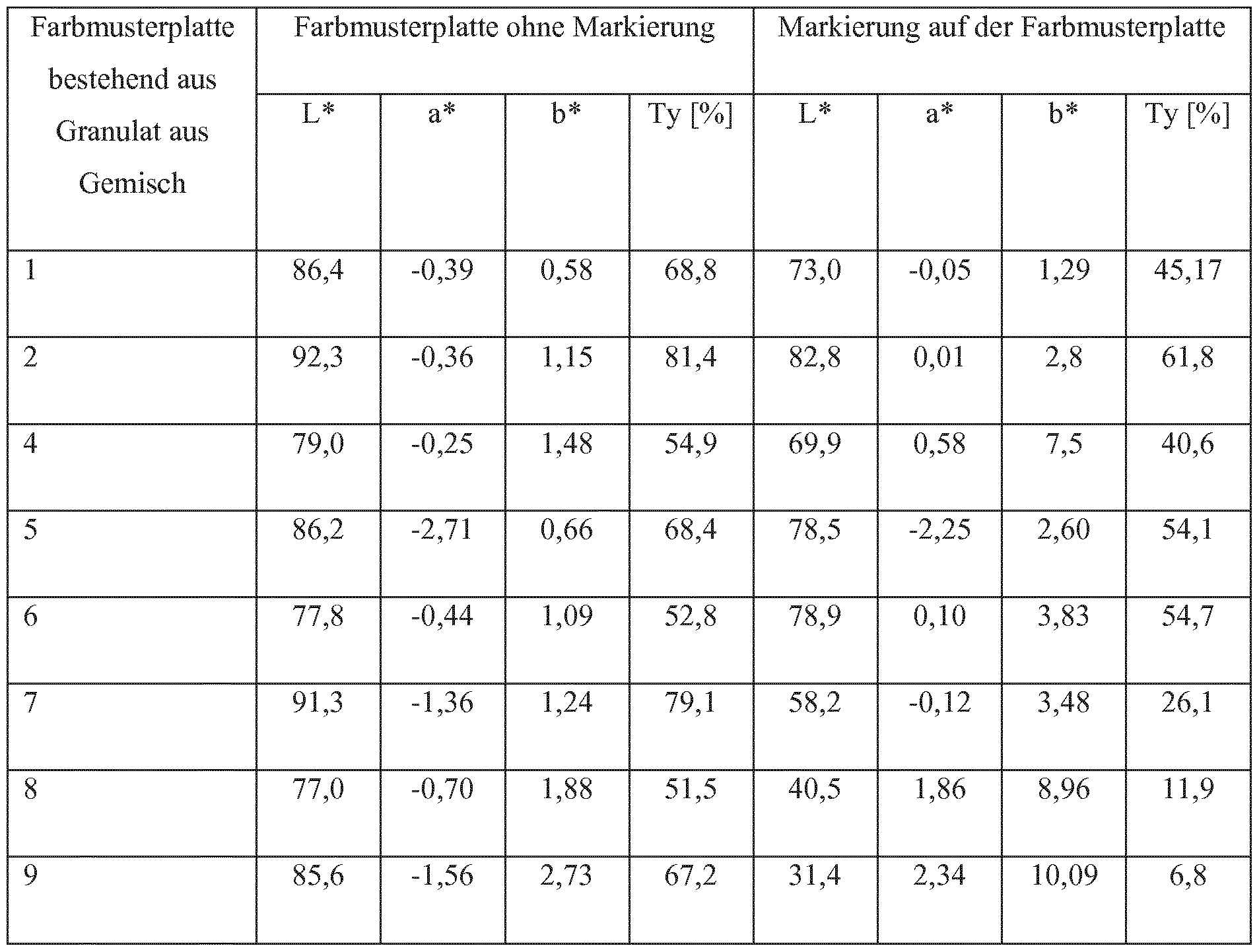
7. Einfluss der Markierung auf die Zähigkeit der Farbmusterplattc mit Zuschlagstoff 7. Influence of the marking on the toughness of the Farbmusterplattc with aggregate
Ein Ensemble von 3 linienformigen Markierungen wurde in einer Breite von 3 mm und einem Abstand von 2 cm auf Farbmusterplatten bestehend aus Granulat der Gemische 1 bis 9 (60 mm xAn ensemble of 3 linear markings was made in a width of 3 mm and a distance of 2 cm on color sample plates consisting of granules of mixtures 1 to 9 (60 mm x
60 mm x 2 mm) bei konstanter Pulsbreite (3 μβ) aufgebracht. 60 mm x 2 mm) at a constant pulse width (3 μβ).
Frequenz: 8,0 [kHz] Vorschubgeschwindigkeit: 725 [mm/s]
An den derart präparierten Farbmusterplatten wurden Durchstoßversuche nach DI EN I SO 6603- 2 durchgeführt. Das Bruchverhalten sowie die Gesamtenergieaufnahme der Farbmusterplatten wurden beim Aufprall des Fallgewichts auf die markierte Seite sowie auf die nicht markierte Seite ermittelt und in nachfolgender Tabel le dargestellt. Wie ersichtlich, zeigt die Markierung der Farbmusterplatten keinen wesentlichen Einfluss auf das Bruchverhalten bzw. auf die Energieaufnahme der Farbmusterplatten. Frequency: 8.0 [kHz] Feed rate: 725 [mm / s] Punching tests in accordance with DI EN I SO 6603-2 were carried out on the color sample plates prepared in this way. The fracture behavior and the total energy absorption of the color sample plates were determined on impact of the drop weight on the marked side and on the non-marked side and presented in the following table. As can be seen, the marking of the color pattern plates has no significant influence on the fracture behavior or on the energy absorption of the color pattern plates.

Die optische Beurteilung der Proben nach erfolgtem Durchstoß wurde nach folgendem Beurteilungsschema durchgeführt. The visual evaluation of the samples after penetration was carried out according to the following evaluation scheme.
Beurteilung Beurteilungskriterium Appraisal assessment criterion
1 kein Riss außerhalb des Dornbereichs
2 radialer / gerader Riss; stabile Ausbreitung; nicht bis zum Rand auf einer oder beiden Seiten des Dornbereichs 1 no crack outside the spine area 2 radial / straight crack; stable spread; not to the edge on one or both sides of the spine area
3 tangentialer / gebogener Riss; umlaufend maximal bis 90°; nicht bis zum Rand auf einer oder beiden Seiten des Dornbereichs 3 tangential / bent crack; circumferential maximum up to 90 °; not to the edge on one or both sides of the spine area
4 tangentialer / gebogener Riss: umlaufend mit mehr als 90°; nicht bis zum Rand auf einer oder beiden Seiten des Dornbereichs 4 tangential / bent crack: circumferential with more than 90 °; not to the edge on one or both sides of the spine area
5 Ausstanzen größerer kompakter Stücke als der Dornbereich 5 punching out larger compact pieces than the mandrel area
6 Probe zerbricht in mehrere Stücke 6 sample breaks into several pieces
8. Herstellung von Bisphenol- A-Polycarbonat-Platten in einer Dicke von 15 mm mit einer modifizierten Coextrusionsschicht: 8. Preparation of Bisphenol A Polycarbonate Plates in a Thickness of 15 mm With a Modified Coextrusion Layer:
Unter der Verwendung von PC 1 ( lineares Bisphenol-A Polycarbonat der Bayer AG, Leverkusen mit einem Schmelzflussindex (MFR) gemäß I SO 1 133 von 6 cm3/ 10 min bei 300°C und 1 ,2 kg Belastung) als Basismaterial für die Extrusion wurden Polycarbonat-Platten in 15 mm Dicke gefertigt. Während der Produktion wurde über einen Coextruder das Gemisch 10 bzw. das Gemisch 1 1 zugeführt, wodurch auf der unteren und oberen Seite der aus PC 1 bestehenden Polycarbonat- Platte eine Außenhaut basierend aus dem jeweiligen Gemisch 10 bzw. 1 1 aufgebracht wurde. 8.1 15 mm dicke Bisphenol- A-Polycarbonat-Platte mit einer beidseitig aufgebrachten 60 μ m dicken Coextrusionsschicht basierend auf Gemisch 10 enthaltend 70 ppm Black Pearls 800. With the use of the PC 1 (linear bisphenol-A polycarbonate of Bayer AG, Leverkusen, Germany (with a melt flow index MFR) according to I SO 1 133 of 6 cm 3/10 min at 300 ° C and 1, 2 kg load) as a base material for the Extrusion polycarbonate sheets were made in 15 mm thickness. During production, the mixture 10 or the mixture 1 1 was supplied via a coextruder, whereby on the lower and upper side of the existing PC 1 polycarbonate plate, an outer skin based on the respective mixture 10 or 1 1 was applied. 8.1 15 mm thick bisphenol A polycarbonate plate with a coated on both sides of 60 micron thick coextrusion layer based on mixture 10 containing 70 ppm Black Pearls 800.
8.2 1 mm dicke Bisphenol-A-Polycarbonat-Platte mit einer beidseitig aufgebrachten 60 μ m dicken Coextrusionsschicht basierend auf Gemisch 1 1 enthaltend 0,03% KH DS 872-G2. 8.2 1 mm thick bisphenol A polycarbonate plate with a coated on both sides of 60 micron thick coextrusion layer based on mixture 1 1 containing 0.03% KH DS 872-G2.
9. Markierungen mit einem UV-Laser Für die Markierung der Platten aus 8.1 und 8.2 wurde ein Lasermarkierungssystem TruMark 6350 der Firma Trumpf basierend auf einem N d : Y VO Lasermed ium , welches eine Laserwel lenlänge von 355 um emittiert, verwendet. Der genutzte Fokusdurchmesser bei einer Optik mit einer Brennweite von 260 mm betrug 57 um. Bei einer Pulsfrequenz von 33 kHz betrug die maxi male Leistung 5 W. Die Markierungen wurden bei einer Pulsbreite von 10 ns durchgeführt.
Figur 6.1 zeigt einen Eindruck über Ergebnisse einer Platte aus 8.1 mit Markierungen durch einen9. Markings with a UV Laser For marking the plates from 8.1 and 8.2, a TruMark 6350 laser marking system from Trumpf was used based on a Nd: Y VO laser medium emitting a laser wavelength of 355 μm. The used focus diameter for an optic with a focal length of 260 mm was 57 μm. At a pulse frequency of 33 kHz, the maximum power was 5 W. The markings were carried out at a pulse width of 10 ns. FIG. 6.1 shows an impression of the results of a plate from FIG. 8.1 with markings by one
UV-Laser. UV laser.
Figur 6.2 zeigt einen Eindruck über Ergebnisse einer Platte aus 8.2 mit Markierungen durch einen UV-Laser. Eine Markierung der Coextrusionsschichten aus 8.1 und 8.2 mit einem UV-Laser ist einwandfrei möglich. Es resultieren homogene und kontraststarke Markierungen auf den Bisphenol-A- Polycarbonat-Platten. FIG. 6.2 shows an impression of the results of a plate from FIG. 8.2 with markings by a UV laser. A marking of the coextrusion layers from 8.1 and 8.2 with a UV laser is perfectly possible. This results in homogeneous and high-contrast markings on the bisphenol A polycarbonate plates.
10. Markierungen mit einem IR-Laser DPL Genesis Marker 163 (8W) 10. Markings with an IR Laser DPL Genesis Marker 163 (8W)
Für die nachfolgenden Markierungsversuche wurde ein Laserbeschriftungssystem der Firma ACI Laser GmbH bestehend aus einer Workstation COMFORT mit DPL Genesis Marker 163 (8W) und der Beschriftungssoftware MagicMarkV3 verwendet. Die Laserstrahlquelle besteht aus einer Anregungsquelle (Laserdiode) gefolgt von einem Linsensystem sowie einem Resonator basierend auf einem Nd:YAG (Neodym dotierter Yttrium Aluminium Granat) Laserkristall zur Strahlerzeugung. Der resultierende Laserstrahl weist eine Wellenlänge von 1064 nm auf und wird über eine Strahlablenkeinheit nach dem Durchgang durch eine F-Theta Optik 100 auf die Platten aus 8.1 und 8.2 fokussiert. For the following labeling experiments a laser marking system of the company ACI Laser GmbH consisting of a workstation COMFORT with DPL Genesis Marker 163 (8W) and the labeling software MagicMarkV3 was used. The laser beam source consists of an excitation source (laser diode) followed by a lens system and a resonator based on a Nd: YAG (neodymium-doped yttrium aluminum garnet) laser crystal for beam generation. The resulting laser beam has a wavelength of 1064 nm and is focused via a beam deflection unit after passing through an F-theta optic 100 to the plates of 8.1 and 8.2.
Die Vorschubgeschwindigkeit des Lasers betrug 500 mm/s und die Pulsfrequenz wurde auf 8 kHz eingestellt. Die Pulsbreite betrug 3 β. Der Abstand der einzelnen Linien aus der die resultierende Markierung zusammengesetzt ist betrug 0, 1 mm (jeweils links in der Figur) sowie 0,05 mm (jeweils rechts in der Figur). The feed rate of the laser was 500 mm / s and the pulse rate was set to 8 kHz. The pulse width was 3 β. The distance of the individual lines from which the resulting mark is composed was 0, 1 mm (left in the figure) and 0.05 mm (each on the right in the figure).
Figur 7.1 zeigt einen Eindruck über Ergebnisse einer Platte aus 8.1 mit Markierungen durch einen IR-Laser. FIG. 7.1 shows an impression of the results of a plate from FIG. 8.1 with markings by an IR laser.
Figur 7.2 zeigt einen Eindruck über Ergebnisse einer Platte aus 8.2 mit Markierungen durch einen IR-Laser. FIG. 7.2 shows an impression of the results of a plate from FIG. 8.2 with markings by an IR laser.
Sowohl für Platten aus Beispiel 8.1 als auch für Platten aus Beispiel 8.2 resultieren im vorliegenden Beispiel 10 unter den gegebenen Bedingungen homogene kontraststarke Markierungen.
Both for plates from Example 8.1 and for plates from Example 8.2 result in the present example 10 under the given conditions homogeneous high-contrast markings.
Claims
1 . Kunststoffformteil umfassend d) mindestens eine Substratschicht, enthaltend mindestens ein thermoplastisches Polymer, wobei die Substratschicht eine Basisschicht und eine daran angrenzende Coextrusionsschicht umfasst und wobei die Coextrusionsschicht mindestens einen I R- Absorber umfasst, e) optional mindestens eine Deckschicht auf mindestens einer Seite der Substratschicht, f) optional eine Primer oder Zwischenschicht zwischen den Schichten a) und b), dadurch gekennzeichnet, dass das Kunststoffformteil in der Substratschicht Markierungen aufweist, die in den markierten Bereichen die Transparenz des Formteils im Wellenlängenbereich von 380 bis 780 nm herabsetzen. 1 . A plastic molding comprising d) at least one substrate layer containing at least one thermoplastic polymer, wherein the substrate layer comprises a base layer and a coextrusion layer adjoining thereto and wherein the coextrusion layer comprises at least one IR absorber, e) optionally at least one cover layer on at least one side of the substrate layer, f) optionally a primer or intermediate layer between the layers a) and b), characterized in that the plastic molded part in the substrate layer has markings which reduce the transparency of the molded part in the wavelength range of 380 to 780 nm in the marked areas.
2. Kunststoffformtei l nach Anspruch 1 , dadurch gekennzeichnet, dass die Coextrusionsschicht mindestens einen UV- Absorber umfasst. 2. Kunststoffformtei l according to claim 1, characterized in that the coextrusion layer comprises at least one UV absorber.
3. Kunststoffformteil nach einem der vorhergehenden Ansprüche, dadurch gekennzeichnet, dass die Markierungen auf der Fläche des Kunststoffformtei ls gleichmäßig / homogen angeordnet sind. 3. Plastic molding according to one of the preceding claims, characterized in that the markings are arranged uniformly / homogeneously on the surface of the Kunststoffformtei ls.
4. Kunststoffformtei l nach einem der vorhergehenden Ansprüche, dadurch gekennzeichnet, dass die Markierungen in der Coextrusionsschicht sind. 4. Kunststoffformtei l according to any one of the preceding claims, characterized in that the markings are in the coextrusion layer.
5. Kunststoffformtei l nach einem der vorhergehenden Ansprüche, dadurch gekennzeichnet, dass die Markierungen keine transparenten Flächenelemente freilassen, deren mittlere Durchmesser größer als 250 mm sind. 5. Kunststoffformtei l according to any one of the preceding claims, characterized in that the markings leave free no transparent surface elements whose average diameter is greater than 250 mm.
6. Kunststoffformteil nach einem der vorhergehenden Ansprüche, dadurch gekennzeichnet, dass die Markierungen, unabhängig von Ihrer Form, einen mittleren Durchmesser von mindestens 5 mm und kleiner als 300 mm aufweisen. 6. Plastic molding according to one of the preceding claims, characterized in that the markings, regardless of their shape, have an average diameter of at least 5 mm and smaller than 300 mm.
7. Kunststoffformteil nach einem der vorhergehenden Ansprüche, dadurch gekennzeichnet, die Markierungen linienformig sind und eine horizontale Ausrichtung aufweisen mit einer Linienbreite von 1 ,5 mm bis 1 5 mm, in einem regelmäßigen Abstand von 1 ,5 cm bis 10,0 cm, wobei der Bedeckungsgrad der Formteiloberfläche von 4 % - 25 % beträgt.
7. Plastic molding according to one of the preceding claims, characterized in that the markings are line-shaped and have a horizontal orientation with a line width of 1, 5 mm to 1 5 mm, at a regular distance of 1, 5 cm to 10.0 cm, wherein the degree of coverage of the molding surface is from 4% to 25%.
8. Kunststoffforniteil nach einem der vorhergehenden Ansprüche, dadurch gekennzeichnet, die Markierungen linientormig sind und eine vertikale Ausrichtung aufweisen mit einer Linienbreite von 3 mm bis 20 mm, in einem regelmäßigen Abstand von 4 cm bis 20 cm, wobei der Bedeckungsgrad der Formteiloberfläche von 2 % - 25 % beträgt. 8. Kunststoffforniteil according to any one of the preceding claims, characterized in that the markings are linear and have a vertical orientation with a line width of 3 mm to 20 mm, at a regular distance of 4 cm to 20 cm, the degree of coverage of the molding surface of 2% - 25%.
9. Kunststoffformteil nach einem der vorhergehenden Ansprüche, dadurch gekennzeichnet, dass die Markierungen nicht linientormig sind und wobei der Bedeckungsgrad der Formteiloberfläche 5 % bis 40 %, weiter bevorzugt 10 % bis 30 %, besonders bevorzugt von 15 % bis 25 % beträgt. 9. Plastic molding according to one of the preceding claims, characterized in that the markings are not linientormig and wherein the degree of coverage of the molding surface is 5% to 40%, more preferably 10% to 30%, particularly preferably from 15% to 25%.
10. Kunststoffformteil nach einem der vorhergehenden Ansprüche, dadurch gekennzeichnet, dass die Markierungen eine Transparenz ( Lichttransmission) von weniger als 5,0 % aufweisen. 10. Plastic molding according to one of the preceding claims, characterized in that the markings have a transparency (light transmission) of less than 5.0%.
1 1. Kunststoffformteil nach einem der vorhergehenden Ansprüche, dadurch gekennzeichnet, dass der Kontrast, definiert als Quotient aus der Differenz aus der Lichttransmission einer nicht markierten und einer markierten Stelle als Dividend sowie der Summe aus Lichttransmission der markierten und nichtmarkierten Stelle als Divisor, der markierten und nichtmarkierten Stelle mindestens 90% beträgt. 1 1. plastic molding according to one of the preceding claims, characterized in that the contrast, defined as the quotient of the difference between the light transmission of a non-marked and a marked digit as a dividend and the sum of light transmission of the marked and unlabeled point as a divisor, the marked and unlabeled body is at least 90%.
12. Kunststoffformteil nach einem der vorhergehenden Ansprüche, dadurch gekennzeichnet, dass der 1 - Absorber in der Coextrusionsschicht ausgewählt ist aus der Gruppe, umfassend Lanthanboride und Ruß. 12. Plastic molding according to one of the preceding claims, characterized in that the 1 - absorber in the coextrusion layer is selected from the group comprising lanthanum borides and carbon black.
13. Kunststoffformteil nach einem der vorhergehenden Ansprüche, dadurch gekennzeichnet, dass das thermoplastische Polymer der Substratschicht Polycarbonat ist. 13. Plastic molding according to one of the preceding claims, characterized in that the thermoplastic polymer of the substrate layer is polycarbonate.
14. Kunststoffformteil nach einem der vorhergehenden Ansprüche, dadurch gekennzeichnet, dass die Markierungen mit einem Nd: YAG-Laser mit 1064 nm Wellenlänge oder einem UV (Ultraviolett)-Laser (Nd:YVO -Laser) mit 55 nm Wellenlänge eingebracht werden. 14. Plastic molding according to one of the preceding claims, characterized in that the markings are introduced with a Nd: YAG laser with 1064 nm wavelength or a UV (ultraviolet) laser (Nd: YVO laser) with a wavelength of 55 nm.
15. Verwendung von Kunststoffformteilen nach einem der Ansprüche 1 bis 14 zur Herstellung von Vogelschutzverglasungen.
15. Use of plastic moldings according to one of claims 1 to 14 for the production of bird protection glazings.
Priority Applications (3)
| Application Number | Priority Date | Filing Date | Title |
|---|---|---|---|
| CN201480005209.5A CN104918485A (en) | 2013-01-18 | 2014-01-16 | Bird protection glazing |
| EP14700876.7A EP2945480B1 (en) | 2013-01-18 | 2014-01-16 | Bird protection glazing |
| US14/761,379 US9713915B2 (en) | 2013-01-18 | 2014-01-16 | Bird protection glazing |
Applications Claiming Priority (2)
| Application Number | Priority Date | Filing Date | Title |
|---|---|---|---|
| EP13151893.8 | 2013-01-18 | ||
| EP13151893 | 2013-01-18 |
Publications (1)
| Publication Number | Publication Date |
|---|---|
| WO2014111473A1 true WO2014111473A1 (en) | 2014-07-24 |
Family
ID=47563278
Family Applications (1)
| Application Number | Title | Priority Date | Filing Date |
|---|---|---|---|
| PCT/EP2014/050810 WO2014111473A1 (en) | 2013-01-18 | 2014-01-16 | Bird protection glazing |
Country Status (4)
| Country | Link |
|---|---|
| US (1) | US9713915B2 (en) |
| EP (1) | EP2945480B1 (en) |
| CN (1) | CN104918485A (en) |
| WO (1) | WO2014111473A1 (en) |
Cited By (1)
| Publication number | Priority date | Publication date | Assignee | Title |
|---|---|---|---|---|
| AT522536A1 (en) * | 2019-05-06 | 2020-11-15 | Birdshades Innovations Gmbh | Component, in particular pane element, with protection against bird strikes and method for producing such a component |
Families Citing this family (5)
| Publication number | Priority date | Publication date | Assignee | Title |
|---|---|---|---|---|
| DE102014002644A1 (en) * | 2014-02-27 | 2015-08-27 | Boraident Gmbh | Method of making a bird protection device and bird protection glass |
| DK3462839T4 (en) * | 2016-05-30 | 2023-06-06 | Svensson Ludvig Ab | ENERGY-SAVING GREENHOUSE SHIELDING |
| CN110734662A (en) * | 2019-09-06 | 2020-01-31 | 长沙壹纳光电材料有限公司 | Cesium tungstate ethanol slurry and preparation process thereof |
| JP6937998B2 (en) * | 2019-12-19 | 2021-09-22 | 大日本印刷株式会社 | Laminated body, and printing or drawing method for the laminated body |
| US20230348739A1 (en) * | 2022-04-29 | 2023-11-02 | N.J. Solar & Safety Film LLC / DBA National National Window Film | Ultraviolet (uv) absorbing inks and films for glass |
Citations (4)
| Publication number | Priority date | Publication date | Assignee | Title |
|---|---|---|---|---|
| DE3402871A1 (en) * | 1984-01-27 | 1985-08-08 | Optische Werke G. Rodenstock, 8000 München | Method for inscribing transparent components with the aid of a YAG laser |
| EP1319335A1 (en) * | 2001-12-13 | 2003-06-18 | Alfred Dr. Meyerhuber | Bird protection device for a transparent material, and glass with a bird protection device |
| EP2179857A1 (en) * | 2008-10-23 | 2010-04-28 | Bayer MaterialScience AG | ID cards with blocked laser engraving writeability |
| DE102011103132A1 (en) * | 2011-05-25 | 2012-11-29 | Isolar Isolierglaserzeugung Gmbh | Panel unit for use with protection structure against bird strike, has support structure consisting of graphically designed coated elements, where protection structure is visible as non-flying obstacle to bird eye |
Family Cites Families (36)
| Publication number | Priority date | Publication date | Assignee | Title |
|---|---|---|---|---|
| DE1031512B (en) | 1955-12-21 | 1958-06-04 | Bayer Ag | Process for the production of high molecular weight fiber and film forming polycarbonates |
| US4185009A (en) | 1975-01-03 | 1980-01-22 | Bayer Aktiengesellschaft | Branched, high-molecular weight thermoplastic polycarbonates |
| DE2500092C3 (en) | 1975-01-03 | 1978-10-12 | Bayer Ag, 5090 Leverkusen | Branched, high molecular weight, thermoplastic and soluble polycarbonates |
| US4101513A (en) | 1977-02-02 | 1978-07-18 | Minnesota Mining And Manufacturing Company | Catalyst for condensation of hydrolyzable silanes and storage stable compositions thereof |
| US4395463A (en) | 1980-06-03 | 1983-07-26 | General Electric Company | Article comprising silicone resin coated, methacrylate-primed substrate |
| DE8233007U1 (en) | 1982-11-25 | 1983-03-24 | Röhm GmbH, 6100 Darmstadt | POLYCARBONATE PLASTIC PANEL |
| DE3244953C2 (en) | 1982-12-04 | 1984-11-29 | Röhm GmbH, 6100 Darmstadt | Process for the production of a hollow plastic sheet |
| US5041313A (en) | 1990-05-11 | 1991-08-20 | General Electric Company | Method for making silicone hardcoat composites and primer compositions |
| US5367044A (en) | 1990-10-12 | 1994-11-22 | General Electric Company | Blow molded article molded from a composition comprising a randomly branched aromatic polymer |
| TW222292B (en) | 1991-02-21 | 1994-04-11 | Ciba Geigy Ag | |
| DE4118232A1 (en) | 1991-06-04 | 1992-12-10 | Bayer Ag | CONTINUOUS PREPARATION OF POLYCARBONATES |
| CA2093686A1 (en) | 1992-05-11 | 1993-11-12 | Gautam A. Patel | Heat curable primerless silicone hardcoat compositions, and thermoplastic composites |
| DE4240313A1 (en) | 1992-12-01 | 1994-06-09 | Bayer Ag | Improved flow polycarbonate(s) for optical data carriers - having Tg 140 deg. C or above and specified melt viscosity |
| US5391795A (en) | 1994-02-18 | 1995-02-21 | General Electric Company | Silylated agents useful for absorbing ultraviolet light |
| DE69509952T2 (en) | 1994-03-04 | 1999-11-04 | Gen Electric | Coatings suitable for the absorption of ultraviolet light |
| EP0790980A1 (en) | 1994-11-10 | 1997-08-27 | Basf Aktiengesellschaft | 2-cyanoacrylic acid esters |
| DE4444868A1 (en) | 1994-12-16 | 1996-06-20 | Bayer Ag | UV-protected, multi-layer polycarbonate sheets |
| CA2203595A1 (en) | 1996-04-26 | 1997-10-26 | Robert F. Hurley | Cross-linked polyolefin tape |
| DE59702969D1 (en) | 1996-10-30 | 2001-03-08 | Ciba Sc Holding Ag | Stabilizer combination for the rotomolding process |
| DE19943642A1 (en) | 1999-09-13 | 2001-03-15 | Bayer Ag | container |
| US6228973B1 (en) | 2000-06-02 | 2001-05-08 | General Electric Company | Method for preparing high molecular weight polycarbonate |
| DE10047483A1 (en) | 2000-09-26 | 2002-04-11 | Bayer Ag | Use of copolycarbonates |
| US20030214070A1 (en) | 2002-05-08 | 2003-11-20 | General Electric Company | Multiwall polycarbonate sheet and method for its production |
| EP1308084A1 (en) | 2002-10-02 | 2003-05-07 | Ciba SC Holding AG | Synergistic UV absorber combination |
| DE10311063A1 (en) | 2003-03-13 | 2004-09-23 | Basf Ag | UV stabilizer composition for transparent plastic packaging, e.g. for cosmetics or food, contains pentaerythritol tetrakis-2-cyano-3,3-diphenylacrylate and a hydroxybenzophenone derivative |
| US7365124B2 (en) | 2004-03-31 | 2008-04-29 | General Electric Company | Flame retardant resin blends based on polymers derived from 2-hydrocarbyl-3,3-bis(4-hydroxyaryl)phthalimidine monomers |
| DE102004022673A1 (en) | 2004-05-07 | 2005-11-24 | Bayer Materialscience Ag | Copolycarbonates with improved flowability |
| DE102005017023A1 (en) | 2005-04-13 | 2006-10-19 | Bayer Materialscience Ag | UV-stabilized polycarbonate moldings |
| US8869480B2 (en) * | 2005-08-25 | 2014-10-28 | Daniel Klem, JR. | Method and apparatus for preventing birds from colliding with or striking flat clear and tinted glass and plastic surfaces |
| DE102006046330A1 (en) | 2006-09-28 | 2008-04-03 | Bayer Materialscience Ag | Polycarbonates and copolycarbonates with improved metal adhesion |
| GB2444053A (en) | 2006-11-23 | 2008-05-28 | Eques Coatings | Hybrid UV-curable resins |
| US7857905B2 (en) | 2007-03-05 | 2010-12-28 | Momentive Performance Materials Inc. | Flexible thermal cure silicone hardcoats |
| DE102007011069A1 (en) | 2007-03-07 | 2008-09-11 | Bayer Materialscience Ag | Polycarbonate composition containing UV absorber |
| JP2011016304A (en) * | 2009-07-09 | 2011-01-27 | Mitsubishi Engineering Plastics Corp | Molded body for laser marking and laser marking method |
| US20130003208A1 (en) | 2011-06-29 | 2013-01-03 | Robert Alsip | Bird Collision Avoidance Treatment for Exterior Glass |
| CN202300070U (en) * | 2011-08-26 | 2012-07-04 | 株式会社丰和化成 | Glass window |
-
2014
- 2014-01-16 EP EP14700876.7A patent/EP2945480B1/en not_active Not-in-force
- 2014-01-16 CN CN201480005209.5A patent/CN104918485A/en active Pending
- 2014-01-16 US US14/761,379 patent/US9713915B2/en not_active Expired - Fee Related
- 2014-01-16 WO PCT/EP2014/050810 patent/WO2014111473A1/en active Application Filing
Patent Citations (4)
| Publication number | Priority date | Publication date | Assignee | Title |
|---|---|---|---|---|
| DE3402871A1 (en) * | 1984-01-27 | 1985-08-08 | Optische Werke G. Rodenstock, 8000 München | Method for inscribing transparent components with the aid of a YAG laser |
| EP1319335A1 (en) * | 2001-12-13 | 2003-06-18 | Alfred Dr. Meyerhuber | Bird protection device for a transparent material, and glass with a bird protection device |
| EP2179857A1 (en) * | 2008-10-23 | 2010-04-28 | Bayer MaterialScience AG | ID cards with blocked laser engraving writeability |
| DE102011103132A1 (en) * | 2011-05-25 | 2012-11-29 | Isolar Isolierglaserzeugung Gmbh | Panel unit for use with protection structure against bird strike, has support structure consisting of graphically designed coated elements, where protection structure is visible as non-flying obstacle to bird eye |
Non-Patent Citations (2)
| Title |
|---|
| HEIKO HAUPT: "Auf dem Weg zu einem neuen Mythos? Warum UV-Glas zur Vermeidung von Vogelschlag noch nicht empfohlen werden kann", BERICHTE ZUM VOGELSCHUTZ, vol. 47/48, 2011, pages 143 - 160, XP055065078 * |
| JOHAN BOSMAN: "Processes and strategies for solid state Q-switch laser marking of polymers", THESIS, UNIVERSITY OF TWENTE, 2007, pages 37,38,160 - 165, XP055065761, ISBN: 978-9-03-652346-2, Retrieved from the Internet <URL:http://doc.utwente.nl/58020/1/thesis_Bosman.pdf> [retrieved on 20130607] * |
Cited By (2)
| Publication number | Priority date | Publication date | Assignee | Title |
|---|---|---|---|---|
| AT522536A1 (en) * | 2019-05-06 | 2020-11-15 | Birdshades Innovations Gmbh | Component, in particular pane element, with protection against bird strikes and method for producing such a component |
| AT522536B1 (en) * | 2019-05-06 | 2021-02-15 | Birdshades Innovations Gmbh | Component, in particular pane element, with protection against bird strike and method for producing such a component |
Also Published As
| Publication number | Publication date |
|---|---|
| CN104918485A (en) | 2015-09-16 |
| EP2945480B1 (en) | 2018-07-25 |
| US20150375485A1 (en) | 2015-12-31 |
| US9713915B2 (en) | 2017-07-25 |
| EP2945480A1 (en) | 2015-11-25 |
Similar Documents
| Publication | Publication Date | Title |
|---|---|---|
| EP2569354B1 (en) | Polymer composition having heat-absorbent properties and improved dyeing properties | |
| EP2652030B1 (en) | Polymer composition having heat-absorbing properties and high resistance to weathering | |
| EP2768895B1 (en) | Polymer compound with heat absorbing characteristics | |
| EP2569353B1 (en) | Polymer composition having heat-absorbent properties and improved dyeing properties | |
| EP2945480B1 (en) | Bird protection glazing | |
| EP2652026B1 (en) | Polymer composition having heat-absorbing properties and high resistance to weathering | |
| EP2569356B1 (en) | Polymer composition having heat-absorbent properties and high stability | |
| EP1287061B1 (en) | Ir-absorbing compositions | |
| EP2513213B1 (en) | Polymer composition having heat-absorbing properties and high stability | |
| EP3541621B1 (en) | Transparent multilayer body for thermal management | |
| EP1261663A1 (en) | Ir absorbing compositions | |
| EP2569360B1 (en) | Stabiliser compositions | |
| EP2632721A1 (en) | Multilayer plastic structure having low energy transmission | |
| WO2014095981A1 (en) | Multi-layer body made of polycarbonate with high weathering resistance | |
| WO2019020478A1 (en) | Led lighting elements comprising molded parts made of translucent polycarbonate compositions having a deep gloss effect | |
| EP3802121B1 (en) | Opaque multilayer bodies made of polycarbonate having a high weathering stability |
Legal Events
| Date | Code | Title | Description |
|---|---|---|---|
| 121 | Ep: the epo has been informed by wipo that ep was designated in this application |
Ref document number: 14700876 Country of ref document: EP Kind code of ref document: A1 |
|
| WWE | Wipo information: entry into national phase |
Ref document number: 2014700876 Country of ref document: EP |
|
| WWE | Wipo information: entry into national phase |
Ref document number: 14761379 Country of ref document: US |
|
| NENP | Non-entry into the national phase |
Ref country code: DE |