WO2014109247A1 - 飛翔害虫捕獲器 - Google Patents
飛翔害虫捕獲器 Download PDFInfo
- Publication number
- WO2014109247A1 WO2014109247A1 PCT/JP2013/084898 JP2013084898W WO2014109247A1 WO 2014109247 A1 WO2014109247 A1 WO 2014109247A1 JP 2013084898 W JP2013084898 W JP 2013084898W WO 2014109247 A1 WO2014109247 A1 WO 2014109247A1
- Authority
- WO
- WIPO (PCT)
- Prior art keywords
- flying
- attracting
- tray
- lid
- trap
- Prior art date
Links
Images


Classifications
-
- A—HUMAN NECESSITIES
- A01—AGRICULTURE; FORESTRY; ANIMAL HUSBANDRY; HUNTING; TRAPPING; FISHING
- A01M—CATCHING, TRAPPING OR SCARING OF ANIMALS; APPARATUS FOR THE DESTRUCTION OF NOXIOUS ANIMALS OR NOXIOUS PLANTS
- A01M1/00—Stationary means for catching or killing insects
- A01M1/10—Catching insects by using Traps
- A01M1/106—Catching insects by using Traps for flying insects
-
- A—HUMAN NECESSITIES
- A01—AGRICULTURE; FORESTRY; ANIMAL HUSBANDRY; HUNTING; TRAPPING; FISHING
- A01M—CATCHING, TRAPPING OR SCARING OF ANIMALS; APPARATUS FOR THE DESTRUCTION OF NOXIOUS ANIMALS OR NOXIOUS PLANTS
- A01M1/00—Stationary means for catching or killing insects
- A01M1/02—Stationary means for catching or killing insects with devices or substances, e.g. food, pheronones attracting the insects
-
- Y—GENERAL TAGGING OF NEW TECHNOLOGICAL DEVELOPMENTS; GENERAL TAGGING OF CROSS-SECTIONAL TECHNOLOGIES SPANNING OVER SEVERAL SECTIONS OF THE IPC; TECHNICAL SUBJECTS COVERED BY FORMER USPC CROSS-REFERENCE ART COLLECTIONS [XRACs] AND DIGESTS
- Y02—TECHNOLOGIES OR APPLICATIONS FOR MITIGATION OR ADAPTATION AGAINST CLIMATE CHANGE
- Y02A—TECHNOLOGIES FOR ADAPTATION TO CLIMATE CHANGE
- Y02A50/00—TECHNOLOGIES FOR ADAPTATION TO CLIMATE CHANGE in human health protection, e.g. against extreme weather
- Y02A50/30—Against vector-borne diseases, e.g. mosquito-borne, fly-borne, tick-borne or waterborne diseases whose impact is exacerbated by climate change
Definitions
- the present invention relates to a flying pest trap that captures flying pests by volatilizing an internal attracting component to the outside.
- flying pest traps For the purpose of controlling flying pests such as fly flies, various flying pest traps with an attractant inside are commercially available. In order to attract flying insects efficiently to the flying insect trap, it is necessary to use an attractant with a high attracting effect and to devise the structure of the flying insect trap. For example, since flying pests tend to stop at the protruding member or the edge of the hole, the attracting effect can be enhanced if the flying pest trap is provided with a structure such as a protrusion or hole that can easily stop flying pests. it is conceivable that.
- Patent Document 1 a square-shaped protruding portion that protrudes upward to give a perching effect to the flying pest. See).
- the flying insect trap of Patent Document 1 is provided with an opening into which the flying insects enter at the side of the projecting part, and the flying insects that have stopped at the projecting part can be attracted from the opening to the inside. Yes.
- the protruding portion that is supposed to give a perch effect is a portion of the lid that bulges upward and is exposed in a square shape. For this reason, even if the flying pest stops at the protruding portion, the flying pest is likely to be visually recognized from the surroundings, and may escape if a person feels a sign or the like.
- the tip of the projecting part where the flying pest is likely to stop is separated from the opening where the flying pest invades, so if the flying pest stops near the tip of the projecting part, the flying pest is smoothly moved to the opening. Can not always lead to.
- the opening part into which a flying pest invades is symmetrically arranged around the projecting part with the same shape. For this reason, the diffusion state of the attracting component released from the opening cannot be changed, and the monotonous and uniform diffusion is likely to occur. As a result, the effect of attracting flying insects may not be sustained.
- the present invention has been made in view of the above-mentioned problems, and in particular, by focusing on the shape of the attracting mouth of the flying insect trap, it is representative of fly flies such as Drosophila, flea flies, mushroom flies, mushroom flies, and fly flies.
- An object of the present invention is to provide a flying insect trap capable of exhibiting an excellent attracting effect against flying insects.
- the characteristic configuration of the flying pest trap according to the present invention for solving the above problems is as follows.
- a flying pest trap that traps flying pests by volatilizing the internal attracting component to the outside,
- a lid portion formed with a plurality of attracting openings for attracting the flying pests inside; While storing the drug part containing the attraction component, a tray part for storing flying pests that have entered the interior from the plurality of attraction openings, With More than half of the plurality of attracting openings have different shapes.
- the flying pest trap of this configuration has a plurality of attracting openings in the lid, and more than half of the attracting openings have different shapes. Therefore, when the attracting component is volatilized to the outside through the attracting port from the drug part housed inside the flying insect trap, the attracting component diffuses in a complicated manner due to the difference in the shape of the attracting port. Therefore, the attracting component can easily reach the flying pests flying in various patterns in various environments, and as a result, the flying pests can be attracted to the flying pest trap effectively and continuously.
- the plurality of attracting openings are preferably formed at random positions with respect to the center of the lid portion when viewed from above.
- the flying pest trap of this configuration since the diffusion state of the attracting component from the attracting port becomes more complicated by randomly arranging a plurality of attracting ports formed in the lid part in a top view, the attracting component Can be diffused over a wide range, and the effect of attracting flying insects to the flying insect trap can be further improved.
- the plurality of attracting openings are preferably formed at positions that are point-symmetric with respect to the center of the lid portion when viewed from above.
- the amount of the attracting component diffused from the attracting port can be made different according to a certain rule by arranging a plurality of attracting ports formed in the lid portion symmetrically.
- the diffusion state of the attracting component can be easily controlled.
- the said cover part has a step part which makes the height position of these induction holes differ.
- the flying pest trap of this configuration by providing the step portion on the lid portion, a plurality of attracting openings are arranged in a step shape, so that the air permeability of the flying pest trap is enhanced and the air flow path Becomes complicated. As a result, the diffusion of the attracting component volatilized from the drug part is promoted, and the attracting effect of flying insects can be further improved.
- the lid part preferably includes an inclined part capable of reflecting light.
- the lid part in which the inclined part of the lid part reflects the light so that the flying part can be surely visually recognized by the flying pest, the lid part on which the flying pest is formed It is possible to attract people effectively.
- At least a part of the tray part has a belt-like protrusion part that contacts the drug part.
- the flying pest trap of this configuration when the flying pest invades from the plurality of attracting openings of the lid, the flying pest is guided to the drug part through the belt-like protrusion provided on the tray part.
- the captured flying pests are reliably guided to a deep position in the tray part where the drug part is installed, and the flying pests that have reached the drug part and are killed are stored in the tray part. I can keep it.
- a recess that engages with the upper end of the belt-like projection is formed on the outer surface of the tray portion.
- the flying pest trap of this configuration when a plurality of tray portions are stacked in the height direction, the upper end of the belt-like protrusion provided on the tray portion is a recess formed on the outer surface of the tray portion stacked thereon
- the space volume can be made compact. As a result, the loading efficiency during product storage and transportation is improved.
- the tray part is preferably configured to be transparent or translucent.
- the flying pest catcher of this configuration the inside of the tray part where the flying pests accumulate can be surely seen from the outside, so it is easy to check the attracting effect and grasp the replacement time, and the flying pests that are easy to handle It can be a trap.
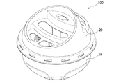
- FIG. 1 is a perspective view of a flying pest trap.
- FIG. 2 is a perspective view of the tray portion.
- FIG. 3 is a side view of the flying pest trap.
- FIG. 4 is a side sectional view of the flying insect trap.
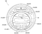
- FIG. 5 is a plan view of the flying pest trap.
- FIG. 6 is a schematic diagram showing the shape of the attracting opening provided in the flying insect trap used in Examples 1 to 6 and Comparative Examples 1 and 2.
- FIG. 1 is a perspective view of a flying insect trap 100 according to an embodiment of the present invention.
- the flying pest trap 100 is used to capture and control various flying pests (particularly fruit flies), and includes a tray unit 10 and a lid unit 20.
- the tray unit 10 and the lid unit 20 will be described in detail.
- FIG. 2 is a perspective view of the tray unit 10 constituting the lower part of the flying pest trap 100.
- the tray unit 10 is a cup-shaped container that stores dead insects. As shown in FIG. 2, the tray unit 10 is configured such that a later-described drug unit 30 is installed at or near the inner bottom thereof, and the flying pests are killed by the insecticidal components contained in the drug held in the drug unit 30. Has been.
- the tray part 10 is provided with an arrangement member 11 for positioning the drug part 30 at substantially the center. In the present embodiment, by restricting the side surface of the drug part 30 with the four arrangement members 11, the drug part 30 is arranged at substantially the center of the tray part 10.
- a fixing part (not shown) is mounted on the arrangement member 11, and the drug part 30 is fixed.
- the tray portion 10 is provided with a flange portion 12 for attaching and detaching a lid portion 20 described later.
- a barrier film (not shown) formed by laminating an aluminum film and a resin film is adhered to the flange portion 12 to seal the inside, and the medicine contained in the medicine portion 30 is dried. Is preventing.
- the barrier film is peeled off from the flange portion 12 and fitted with the lid portion 20 with the inside exposed.
- a belt-like protrusion 13 for guiding the flying pests to the drug part 30 is provided on the inner side surface of the tray part 10.
- four strip-shaped protrusions 13 are provided at equal intervals on the inner side surface of the tray unit 10.
- the size of one band-like protrusion 13 is set to a width of 3 to 10 mm, a thickness of 0.5 to 3 mm, and a length of 10 to 30 mm.
- Each of the band-shaped protrusions 13 is provided over a range from the flange 12 to the vicinity of the root of the arrangement member 11.
- the drug part 30 is installed so as to be in contact with at least a part of each belt-like projection part 13.
- the flying pest that has entered the inside of the flying pest trap 100 moves toward the drug part 30 below while traveling along the belt-like protrusion 13. And if it reaches
- the captured flying pest is reliably guided to a deep position of the tray unit 10 where the drug unit 30 is installed, and the drug unit 30.
- the flying pests that have reached and died can be stored in the tray section 10.
- the drug unit 30 installed in the tray unit 10 volatilizes the attracting component contained in the soaked drug to the outside, attracts the flying pests to the inside of the flying pest trap 100, and attracted flying.
- the insecticide is killed by contacting or ingesting the insecticide contained in the drug against the pest.
- the drug part 30 is obtained by soaking a drug in an absorbent carrier.
- a carrier for example, a pulp nonwoven fabric or felt can be used. In order to make the carrier thick, a plurality of thin pulp nonwoven fabrics or felts may be laminated. In order to efficiently absorb the drug while maintaining the shape of the pulp nonwoven fabric or felt, a web can be formed on the surface or embossed by the spunlace method.
- the carrier of the drug part 30 may be composed of sponge, paper, fiber aggregate, etc. that can absorb liquid.
- a liquid attracting component and an insecticidal component mixed into a gel may be used as the drug part 30.
- the medicine includes an attractant for causing the flying pests to enter the inside of the tray unit 10 and an insecticide for killing the flying pests.
- attractants include balsamic vinegar, apple vinegar, rice vinegar, brown rice vinegar, rice vinegar, soybean vinegar, black vinegar, wine vinegar, sudachi vinegar, red vinegar, straw vinegar, malt vinegar, purple potato vinegar, sugarcane vinegar, etc. These may be used alone or in combination.
- balsamic vinegar is particularly preferable because of its excellent attracting effect against flying pests.
- Insecticides include, for example, allethrin, praretrin, imiprothrin, phthalthrin, transfluthrin, resmethrin, phenothrin, ciphenothrin, permethrin, cypermethrin, etofenprox, cyfluthrin, deltamethrin, bifenthrin, fenvalerate, fenpropathrin, empfenthrin, silafluoline , Methofluthrin, profluthrin, natural pyrethrin, pyrethroid compounds such as Pyrethrum extract, carbaryl, propoxur, mesomil, carbamate compounds such as thiodicarb, organic phosphorus compounds such as fenitrothion, diazinon, marathon, pyridafenthion, prothiophos, phoxime, chlorpyrifos, dichlorvos , Oxadiazole
- dinotefuran which is a neonicotinoid compound
- dinotefuran which is a neonicotinoid compound
- it has low repellency against flying insects and does not inhibit the attracting action of the attracting agent.
- attractants and insecticides for example, alcoholic beverages, sake lees, sugars, fruits, fruit processed products, lactic acid products, seafood, processed seafood products, seafood extracts, meat, processed meat products
- Other attractants such as meat extract and fragrance may be included.
- a moisturizing component such as an aliphatic polyhydric alcohol such as glycerin, a sugar alcohol such as sorbitol, or a thickening polysaccharide such as xanthan gum is included, the efficacy of the drug can be exhibited over a long period of time.
- the tray unit 10 and the lid unit 20 are configured to be detachable, the lid unit 20 is removed as necessary to replace the drug unit 30 inside the tray unit 10 or to attract the inside of the tray unit 10. It is possible to take out the dead bodies of flying pests that have been killed.
- the horizontal section of the tray unit 10 is configured to be rectangular, circular, or the like so that it can be easily installed in a living space such as a kitchen or living room, but may be indefinite.
- the bottom area of the tray unit 10 is set to about 10 to 100 cm 2 so that the flying pest trap 100 can be installed without conspicuous. Further, when the depth of the tray part 10 is set to about 1 to 10 cm, the drug part 30 is reliably installed and the stability is improved.
- the tray unit 10 is formed into a cup shape by injection molding, vacuum molding, bulging molding, blow molding, or the like using a thermoplastic resin.
- a recess 14 is formed on the outer surface of the tray 10 to engage with the belt-like protrusion 13.
- the recess 14 is provided in order to improve the loading efficiency of the tray unit 10.
- the upper ends of the strip-shaped protrusions 13 provided on the outer surface of the tray portion 10 are placed on the outer surface of the tray portion 10 stacked thereon. Engages with the formed recess 14. For this reason, it becomes possible to stack a plurality of tray sections 10 in a compact manner, and the loading efficiency during storage and transportation of products is improved.
- the tray unit 10 is preferably configured to be transparent or translucent.
- the flying pest trap 100 can be easily handled by confirming the attracting effect and grasping the replacement time. be able to.
- a colorless material such as polypropylene resin, PET resin, acrylic resin, polyethylene resin, polystyrene resin or the like is used as the material of the tray unit 10.
- the thickness of the tray part 10 may be formed thin so that the inside can be seen through.
- FIG. 3 is a side view of the flying insect trap 100 with the lid 20 attached to the tray 10.
- FIG. 4 is a side sectional view of the flying pest trap 100.
- FIG. 5 is a plan view of the flying pest trap 100 as seen from the lid 20 side.
- the lid part 20 attracts flying insects by introducing outside air into the flying insect trap 100 and diffusing an attracting component from the drug part 30 to the outside.
- the cover part 20 prevents the medicine part 30 accommodated in the tray part 10 from being exposed.
- the lid portion 20 includes an attracting structure portion 21 that attracts flying pests and a connection portion 22 that engages with the flange portion 12 of the tray portion 10.
- the lid portion 20 is formed by injection molding using a thermoplastic resin, vacuum molding, bulging molding, blow molding, or the like, and as shown in FIG. 4, the hollow structure in which the attracting structure portion 21 and the connection portion 22 are integrated. Configured as a structure.
- the attracting structure 21 includes a plurality of attracting openings 23 that attract the flying pests into the flying pest trap 100.
- the attracting structure part 21 is composed of four step parts 21a to 21d having different heights.
- attracting ports 23a to 23e are formed in the respective step portions 21a to 21d.
- FIG. 4 is a side sectional view passing through the center of the flying pest trap 100 (point P in FIG. 5), so that the induction port does not appear in the step portion 21c, but in reality, the induction port is formed in the step portion 21c. 23c and 23d are formed.
- the step portions 21a to 21c are provided adjacent to each other in order, and the step portion 21d is provided on the opposite side of the step portion 21a.
- the step portion 21a is formed with an induction port 23a
- the step portion 21b is formed with an induction port 23b
- the step portion 21c is formed with induction ports 23c and 23d
- the step portion 21d is formed with an induction port 23e.
- the induction ports 23a to 23e formed in the respective step portions 21a to 21d have shapes different from each other in more than half.
- “Different shapes” means shapes that do not completely match when superimposed. Therefore, for example, a similar shape or a shape having a line symmetry (mirror image) relationship does not completely coincide with each other even if they are overlapped with each other.
- the plurality of attracting openings 23 formed in the attracting structure portion 21 are most preferable if they all have different shapes, but this is not essential, and more than half of the attracting openings 23 have different shapes. If you do.
- the attracting ingredients included in the drug part 30 inside the flying insect trap 100 are volatilized to the outside via the attracting openings 23.
- the attracting component is released while diffusing in a complicated manner due to the difference in the shape of 23. Therefore, the attracting component can easily reach the flying pests flying in various patterns in various environments, and as a result, the flying pests can be attracted to the flying pest trap 100 effectively and continuously.
- the attracting openings 23a to 23e are formed at random positions or point-symmetric positions with respect to the center of the lid portion 20 when viewed from above.
- the “center of the lid portion 20” corresponds to the position of the center of gravity of the shape in a top view.
- the center of the circle corresponds to the center P of the lid 20.
- “Random position with respect to the center P of the lid 20” means the distance from the center P of the lid 20 to the attracting openings 23a to 23e and the respective attracting openings 23a.
- the plurality of attracting openings 23 are formed in the lid portion 20 so as to be substantially irregularly arranged in a top view.
- diffusion of the attracting components from the attracting openings 23 becomes more complicated, so that the attracting components can be diffused over a wide range, and flying insect pests.
- the effect of attracting flying insects to the trap 100 can be further improved.
- the attracting openings 23a to 23e are formed at positions that are point-symmetric with respect to the center P of the lid portion 20 in a top view, the diffusion amount of the attracting components from the attracting openings 23a to 23e is determined according to a certain rule.
- the diffusion state of the attracting component can be easily controlled.
- the attracting component can be diffused upward so as to form a vortex with a perpendicular passing through the center P of the lid 20 as an axis to enhance the effect of attracting the flying pest to the flying pest trap 100 in a specific direction. It becomes.
- the attracting structure portion 21 includes an inclined portion 24 that can reflect light.
- the inclined portion 24 is provided so as to surround the step portions 21a to 21c.
- the inclined portion 24 reflects light, so that the lid 20 can be surely visually recognized by the flying pest, and the flying pest can be effectively attracted toward the lid 20 where the attracting port 23 is formed.
- the inclination angle of the inclined portion 24 is preferably set to 15 degrees or more with respect to the connecting portion 22 in a side view.
- connection unit 22 connects the attracting structure unit 21 to the tray unit 10.
- the connection part 22 is comprised in the shape which can receive the flange part 12 of the tray part 10.
- the connection part 22 may be screwed into the flange part 12.
- the color tone (object color) of the tray unit 10 and the lid unit 20 was determined based on the L * a * b * color system.
- the L * a * b * color system is a three-dimensional approximate uniform color space recommended by the International Commission on Illumination (CIE) in 1976 to express lightness, hue, and saturation.
- the L * a * b * color system (CIE 1976) is defined as JIS Z 8729 in the Japanese Industrial Standard.
- L * is an index representing lightness
- L *: 0 is black
- L *: 100 is white.
- a * and b * are indices representing hue and saturation.
- L * a * b * color system for example, a C light source that is a standard light source is used and measured at a viewing angle of 10 degrees.
- the lightness, hue, and saturation in the L * a * b * color system are measured using, for example, a color difference meter (for example, a color and color meter “CR-400” manufactured by Konica Minolta Co., Ltd.)
- the measurement is performed using a color densitometer (for example, a spectral color densitometer “X-Rite 939” manufactured by Nippon Flat Equipment Co., Ltd.).
- the tray part 10 and the lid part 20 constituting the flying pest trap 100 are both L *: 20 or more, a *: 0 or more, b in the L * a * b * color system (CIE 1976). *: It was set so that it had a color tone of 0 or more and at least one of both a * and b * had a different color tone.
- L *: 20 or more means that the tray unit 10 and the lid unit 20 have a certain level of brightness.
- a *: 0 or more, b *: 0 or more means that the tray 10 and the lid 20 are red to brown to yellow.
- the color tone of the tray portion 10 and the lid portion 20 is different from each other.
- the a * and b * of the tray part 10 and the lid part 20 are set so that the difference between both a * and / or the difference between both b * is 10 or more. That is, only the difference of a * between the tray part 10 and the lid part 20 is 10 or more, only the difference of b * is 10 or more, and both the difference of a * and the difference of b * are 10 or more.
- the tray unit 10 and the lid unit 20 have a lightness of a certain level or more and a relatively high hue and saturation. You can be attracted to 100.
- a flying pest trap 100 that is easy to handle and that can visually inspect the inside of the tray 10 where the flying pests accumulate while attracting the flying pests effectively toward the lid 20 is designed. can do.
- the color of the lid 20 is L *: 30 * or more, a *: 15 or more, b *: L * a * b * color system (CIE1976).
- the color tone of the tray unit 10 is set to L *: 40 or more, a *: 5 or more, b *: 5 or more in the L * a * b * color system (CIE 1976).
- the color tone of the lid 20 is set to L *: 30 or higher, a *: 30 or higher, b *: 20 or higher in the L * a * b * color system (CIE 1976).
- the color tone is set to L *: 40 or more, a *: 10 or more, b *: 10 or more in the L * a * b * color system (CIE 1976).
- CIE 1976 color system
- the lid portion 20 has an orange color tone and the tray portion 10 has a brown color tone. Since the flying pest exhibits a particularly favorable reaction (attracting property) with respect to this color combination, it is possible to attract and capture the flying pest more efficiently inside the flying pest trap 100.
- a pigment or a colorant is mixed with a resin as a raw material when the tray unit 10 and the lid unit 20 are molded.
- molding may be sufficient.
- the flying pest trap 100 having the color tone set as described above has a higher effect of attracting flying pests by combining the color of the tray portion 10 and the color of the lid portion 20, and also has an attracting component that evaporates from the drug portion 30. Combined with the flying pest attracting effect, a remarkable attracting effect (synergistic effect) can be exhibited.
- the tray portion 10 can be configured to be transparent or translucent
- the lid portion 20 can also be configured to be transparent or translucent.
- the flying insect trap 100 can easily visually recognize the inside of the tray part 10 without removing the lid part 20 while maintaining a high attraction effect.
- the lid 20 preferably has an orange color tone, but the lid 20 may be colored in a color close to black. In this case, since the dead body of the flying pest accumulated inside the tray portion 10 is difficult to see from above, it is difficult to give an unpleasant impression to the user.
- FIG. 6 is a schematic diagram showing the shape of the attracting opening provided in the flying insect trap used in Examples 1 to 6 and Comparative Examples 1 and 2. It should be noted that the total area of the attracting holes was adjusted to be 960 mm 2 in all the examples and comparative examples.
- Each part constituting the flying pest trap was produced as follows.
- Tray part A tray part was produced by injection molding polypropylene (PP) resin. The appearance of the tray portion is light brown.
- Lid A lid was produced by vacuum molding polyethylene terephthalate (PET) resin. The outer appearance of the lid is orange.
- Drug part A drug part was prepared by impregnating a pulp nonwoven fabric as a carrier with a drug. The pulp nonwoven fabric has a size of length 50 mm ⁇ width 50 mm ⁇ thickness 17 mm. The drug contains balsamic vinegar and tri-sugar as an attracting component, dinotefuran as an insecticidal component, glycerin as a moisturizing component, and purified water as other components.
- Example 1 is a catcher having an attracting port of FIG. 6 (a)
- Example 2 is a catcher having an attracting port of FIG. 6 (b)
- Example 3 is an attracting port of FIG. 6 (c).
- the catcher having Comparative Example 1 the catcher having the attracting port of FIG. 6D, and the Comparative Example 2 using the catcher having the attracting port of FIG. As shown in FIG.
- the attracting ports 23a to 23e are randomly arranged with respect to the center P of the lid, and the trap (b) of the second embodiment and the implementation are performed.
- the attracting ports 23a to 23e are arranged point-symmetrically with respect to the center P of the lid, and the trap (d) of Comparative Example 1 and the trap (e) of Comparative Example 2 ), The attracting openings 23a to 23e are arranged completely symmetrically with respect to the center P of the lid.
- the results of Test 1 are shown in Table 1.
- Example 1 and Comparative Example 1 are the same as Example 1 and Comparative Example 1 described in Test 1.
- the arrangement of the attracting openings is substantially the same as that of Example 1, and the opening area and shape of the attracting openings, and the total of the opening areas and the irregular shape ratio are the same as those in Example 1, but the lid portion is illustrated in FIG. 4 and a step as shown in FIG. 5 are provided.
- Example 2 As shown in Table 2, it was recognized that the capture performance was further improved as compared with Example 1 when the lid part was provided with a step part that varied the height positions of the plurality of attracting openings (Example 4). The comparison with Comparative Example 1 was 2.4 times.
- Example 3 The capturing performance of the flying insect trap when the inclined portion capable of reflecting light was provided on the lid was confirmed.
- the results of Test 3 are shown in Table 3.
- Example 1, Example 4, and Comparative Example 1 are the same as Example 1, Example 4, and Comparative Example 1 described in Test 2.
- Example 5 the arrangement of the attracting openings is substantially the same as in Example 4, and the opening area and shape of the attracting openings, the sum of the opening areas and the irregular shape ratio, and the step portion are also the same as in Example 4.
- the lid portion is provided with an inclined portion as shown in FIGS.
- Example 5 As shown in Table 3, it was recognized that when the inclined portion capable of reflecting light was provided on the lid (Example 5), the capture performance was further improved as compared with Example 4. In comparison with Comparative Example 1, it was 2.7 times.
- Example 4 The capturing performance of the flying insect trap was confirmed when the tray portion was provided with a belt-like projection for guiding the flying insect to the drug portion.
- the results of Test 4 are shown in Table 4.
- Example 1, Example 4, Example 5, and Comparative Example 1 are the same as Example 1, Example 4, Example 5, and Comparative Example 1 described in Test 3.
- Example 6 is substantially the same as Example 5 in the arrangement of the attracting openings, and has an opening area and shape of the attracting openings, a total of the opening areas and a different shape ratio, and a step portion and an inclined portion. Although the same, a belt-like protrusion as shown in FIG. 2 is provided on the tray.
- Example 6 As shown in Table 4, it was recognized that the trapping performance was further improved over that of Example 5 when the tray portion was provided with a belt-like protrusion for guiding the flying pests to the drug part (Example 6). In comparison with Comparative Example 1, it was 2.9 times.
- the flying pest traps (Examples 1 to 6) having the configuration of the present invention can exhibit a high capture performance against fruit flies such as Drosophila and are useful insect repellent products. confirmed.
- the flying insect trap of the present invention can be suitably used for flying insects, particularly for fruit flies such as Drosophila, flea flies, mushroom flies, mushroom flies, butterflies, but house flies, black flies, yellow flies, powder flies, etc. It can also be used against flies.
- fruit flies such as Drosophila, flea flies, mushroom flies, mushroom flies, butterflies, but house flies, black flies, yellow flies, powder flies, etc. It can also be used against flies.
Landscapes
- Life Sciences & Earth Sciences (AREA)
- Pest Control & Pesticides (AREA)
- Engineering & Computer Science (AREA)
- Insects & Arthropods (AREA)
- Wood Science & Technology (AREA)
- Zoology (AREA)
- Environmental Sciences (AREA)
- Catching Or Destruction (AREA)
- Health & Medical Sciences (AREA)
- General Health & Medical Sciences (AREA)
- Toxicology (AREA)
Priority Applications (6)
| Application Number | Priority Date | Filing Date | Title |
|---|---|---|---|
| KR1020157017345A KR20150090229A (ko) | 2013-01-11 | 2013-12-26 | 비상 해충 포획기 |
| AU2013373230A AU2013373230B2 (en) | 2013-01-11 | 2013-12-26 | Flying insect pest trap |
| JP2014556383A JP6046166B2 (ja) | 2013-01-11 | 2013-12-26 | 飛翔害虫捕獲器 |
| CN201380064489.2A CN104853603B (zh) | 2013-01-11 | 2013-12-26 | 飞行害虫捕捉器 |
| EP13870653.6A EP2944191B1 (en) | 2013-01-11 | 2013-12-26 | Flying insect pest trap |
| HK15112770.4A HK1211793A1 (zh) | 2013-01-11 | 2015-12-28 | 飛行害蟲捕捉器 |
Applications Claiming Priority (2)
| Application Number | Priority Date | Filing Date | Title |
|---|---|---|---|
| JP2013-003190 | 2013-01-11 | ||
| JP2013003190 | 2013-01-11 |
Publications (1)
| Publication Number | Publication Date |
|---|---|
| WO2014109247A1 true WO2014109247A1 (ja) | 2014-07-17 |
Family
ID=51166903
Family Applications (1)
| Application Number | Title | Priority Date | Filing Date |
|---|---|---|---|
| PCT/JP2013/084898 WO2014109247A1 (ja) | 2013-01-11 | 2013-12-26 | 飛翔害虫捕獲器 |
Country Status (8)
| Country | Link |
|---|---|
| EP (1) | EP2944191B1 (zh) |
| JP (1) | JP6046166B2 (zh) |
| KR (1) | KR20150090229A (zh) |
| CN (1) | CN104853603B (zh) |
| AU (1) | AU2013373230B2 (zh) |
| HK (1) | HK1211793A1 (zh) |
| TW (1) | TWI592093B (zh) |
| WO (1) | WO2014109247A1 (zh) |
Cited By (2)
| Publication number | Priority date | Publication date | Assignee | Title |
|---|---|---|---|---|
| USD928907S1 (en) | 2019-10-23 | 2021-08-24 | S. C. Johnson & Son, Inc. | Bait station |
| US20230038073A1 (en) * | 2020-01-30 | 2023-02-09 | Manoj Kumar R | Delivery system embedded trap device for attracting female and male fruit flies |
Families Citing this family (4)
| Publication number | Priority date | Publication date | Assignee | Title |
|---|---|---|---|---|
| ES2589814B1 (es) * | 2016-09-12 | 2017-09-05 | Ecologia Y Proteccion Agricola, S.L. | Dispositivo trampa para insectos. |
| CN110074081A (zh) * | 2019-05-28 | 2019-08-02 | 浙江省疾病预防控制中心 | 一种电动吸蚊器 |
| JP7334007B2 (ja) * | 2019-08-13 | 2023-08-28 | アース製薬株式会社 | ハチ捕獲器 |
| KR102345364B1 (ko) * | 2019-11-28 | 2021-12-30 | 이동하 | 복숭아유리나방 포획 장치 |
Citations (2)
| Publication number | Priority date | Publication date | Assignee | Title |
|---|---|---|---|---|
| JP2010057502A (ja) | 2006-11-21 | 2010-03-18 | Earth Chem Corp Ltd | 害虫捕獲器 |
| JP2012139202A (ja) * | 2011-01-06 | 2012-07-26 | Dainippon Jochugiku Co Ltd | 飛翔害虫捕獲装置 |
Family Cites Families (5)
| Publication number | Priority date | Publication date | Assignee | Title |
|---|---|---|---|---|
| JP3740660B2 (ja) * | 2001-11-20 | 2006-02-01 | フマキラー株式会社 | 飛翔昆虫用捕獲器 |
| CN102119679A (zh) * | 2006-11-21 | 2011-07-13 | 地球制药株式会社 | 害虫捕获器 |
| ES1071189Y (es) * | 2009-10-16 | 2010-05-05 | Es De Desarrollos Quimicos S L | Dispositivo de trampeo para insectos frugivoros |
| JP5341041B2 (ja) * | 2010-09-06 | 2013-11-13 | 株式会社小松製作所 | 油圧駆動式の車両、およびその制御方法と装置 |
| JP5773656B2 (ja) * | 2011-01-06 | 2015-09-02 | 大日本除蟲菊株式会社 | 飛翔害虫捕獲具 |
-
2013
- 2013-12-26 KR KR1020157017345A patent/KR20150090229A/ko not_active Application Discontinuation
- 2013-12-26 JP JP2014556383A patent/JP6046166B2/ja active Active
- 2013-12-26 CN CN201380064489.2A patent/CN104853603B/zh not_active Expired - Fee Related
- 2013-12-26 EP EP13870653.6A patent/EP2944191B1/en not_active Not-in-force
- 2013-12-26 AU AU2013373230A patent/AU2013373230B2/en not_active Ceased
- 2013-12-26 WO PCT/JP2013/084898 patent/WO2014109247A1/ja active Application Filing
-
2014
- 2014-01-06 TW TW103100318A patent/TWI592093B/zh not_active IP Right Cessation
-
2015
- 2015-12-28 HK HK15112770.4A patent/HK1211793A1/zh not_active IP Right Cessation
Patent Citations (2)
| Publication number | Priority date | Publication date | Assignee | Title |
|---|---|---|---|---|
| JP2010057502A (ja) | 2006-11-21 | 2010-03-18 | Earth Chem Corp Ltd | 害虫捕獲器 |
| JP2012139202A (ja) * | 2011-01-06 | 2012-07-26 | Dainippon Jochugiku Co Ltd | 飛翔害虫捕獲装置 |
Cited By (3)
| Publication number | Priority date | Publication date | Assignee | Title |
|---|---|---|---|---|
| USD928907S1 (en) | 2019-10-23 | 2021-08-24 | S. C. Johnson & Son, Inc. | Bait station |
| USD946690S1 (en) | 2019-10-23 | 2022-03-22 | S. C. Johnson & Son, Inc. | Bait station |
| US20230038073A1 (en) * | 2020-01-30 | 2023-02-09 | Manoj Kumar R | Delivery system embedded trap device for attracting female and male fruit flies |
Also Published As
| Publication number | Publication date |
|---|---|
| EP2944191B1 (en) | 2018-07-25 |
| EP2944191A1 (en) | 2015-11-18 |
| EP2944191A4 (en) | 2016-11-30 |
| CN104853603A (zh) | 2015-08-19 |
| JP6046166B2 (ja) | 2016-12-14 |
| TWI592093B (zh) | 2017-07-21 |
| CN104853603B (zh) | 2017-03-29 |
| TW201438574A (zh) | 2014-10-16 |
| AU2013373230B2 (en) | 2016-04-28 |
| AU2013373230A1 (en) | 2015-06-18 |
| KR20150090229A (ko) | 2015-08-05 |
| JPWO2014109247A1 (ja) | 2017-01-19 |
| HK1211793A1 (zh) | 2016-06-03 |
Similar Documents
| Publication | Publication Date | Title |
|---|---|---|
| JP6046166B2 (ja) | 飛翔害虫捕獲器 | |
| JP5138786B2 (ja) | 飛翔害虫捕獲装置 | |
| JP4450858B2 (ja) | 害虫捕獲器 | |
| TW568746B (en) | Device for controlling insects | |
| US20080196296A1 (en) | Fruit-Shaped Fruit Fly Trap | |
| JP6029690B2 (ja) | 飛翔昆虫捕獲器 | |
| JP6254444B2 (ja) | 飛翔害虫捕獲器 | |
| JP5856560B2 (ja) | アリ毒餌剤容器 | |
| TW200826839A (en) | Device for capturing pest insect | |
| JP6879735B2 (ja) | 飛翔害虫捕獲器 | |
| WO2017069220A1 (ja) | 害虫捕獲方法および害虫捕獲器 | |
| JP2022105635A (ja) | 飛翔害虫捕獲器 | |
| JP2017063754A (ja) | 害虫を捕獲するための器具 | |
| JP5773656B2 (ja) | 飛翔害虫捕獲具 | |
| JP2021078518A (ja) | 飛翔害虫捕獲器 | |
| EP4129059A1 (en) | Fly killing bait station | |
| JP2002291391A (ja) | 不快害虫の誘引捕獲容器 | |
| US10568315B2 (en) | Domestic insect trap | |
| CN2901871Y (zh) | 一种杀虫方便盒 | |
| JP2022191632A (ja) | 紙製捕獲容器 | |
| TWM309866U (en) | Novel flycatcher structure |
Legal Events
| Date | Code | Title | Description |
|---|---|---|---|
| 121 | Ep: the epo has been informed by wipo that ep was designated in this application |
Ref document number: 13870653 Country of ref document: EP Kind code of ref document: A1 |
|
| ENP | Entry into the national phase |
Ref document number: 2014556383 Country of ref document: JP Kind code of ref document: A |
|
| ENP | Entry into the national phase |
Ref document number: 2013373230 Country of ref document: AU Date of ref document: 20131226 Kind code of ref document: A |
|
| ENP | Entry into the national phase |
Ref document number: 20157017345 Country of ref document: KR Kind code of ref document: A |
|
| NENP | Non-entry into the national phase |
Ref country code: DE |
|
| WWE | Wipo information: entry into national phase |
Ref document number: 2013870653 Country of ref document: EP |
|
| WWE | Wipo information: entry into national phase |
Ref document number: IDP00201504867 Country of ref document: ID |