WO2014109200A1 - Drilling method, jig for drilling, and heat exchanger - Google Patents
Drilling method, jig for drilling, and heat exchanger Download PDFInfo
- Publication number
- WO2014109200A1 WO2014109200A1 PCT/JP2013/084070 JP2013084070W WO2014109200A1 WO 2014109200 A1 WO2014109200 A1 WO 2014109200A1 JP 2013084070 W JP2013084070 W JP 2013084070W WO 2014109200 A1 WO2014109200 A1 WO 2014109200A1
- Authority
- WO
- WIPO (PCT)
- Prior art keywords
- plate member
- hole
- jig
- drilling
- holes
- Prior art date
Links
Images


Classifications
-
- B—PERFORMING OPERATIONS; TRANSPORTING
- B23—MACHINE TOOLS; METAL-WORKING NOT OTHERWISE PROVIDED FOR
- B23B—TURNING; BORING
- B23B39/00—General-purpose boring or drilling machines or devices; Sets of boring and/or drilling machines
- B23B39/04—Co-ordinate boring or drilling machines; Machines for making holes without previous marking
- B23B39/06—Equipment for positioning work
-
- B—PERFORMING OPERATIONS; TRANSPORTING
- B23—MACHINE TOOLS; METAL-WORKING NOT OTHERWISE PROVIDED FOR
- B23B—TURNING; BORING
- B23B2247/00—Details of drilling jigs
- B23B2247/12—Drilling jigs with means to affix the jig to the workpiece
-
- B—PERFORMING OPERATIONS; TRANSPORTING
- B23—MACHINE TOOLS; METAL-WORKING NOT OTHERWISE PROVIDED FOR
- B23B—TURNING; BORING
- B23B47/00—Constructional features of components specially designed for boring or drilling machines; Accessories therefor
- B23B47/28—Drill jigs for workpieces
-
- B—PERFORMING OPERATIONS; TRANSPORTING
- B23—MACHINE TOOLS; METAL-WORKING NOT OTHERWISE PROVIDED FOR
- B23B—TURNING; BORING
- B23B47/00—Constructional features of components specially designed for boring or drilling machines; Accessories therefor
- B23B47/28—Drill jigs for workpieces
- B23B47/287—Jigs for drilling plate-like workpieces
-
- B—PERFORMING OPERATIONS; TRANSPORTING
- B23—MACHINE TOOLS; METAL-WORKING NOT OTHERWISE PROVIDED FOR
- B23Q—DETAILS, COMPONENTS, OR ACCESSORIES FOR MACHINE TOOLS, e.g. ARRANGEMENTS FOR COPYING OR CONTROLLING; MACHINE TOOLS IN GENERAL CHARACTERISED BY THE CONSTRUCTION OF PARTICULAR DETAILS OR COMPONENTS; COMBINATIONS OR ASSOCIATIONS OF METAL-WORKING MACHINES, NOT DIRECTED TO A PARTICULAR RESULT
- B23Q3/00—Devices holding, supporting, or positioning work or tools, of a kind normally removable from the machine
- B23Q3/02—Devices holding, supporting, or positioning work or tools, of a kind normally removable from the machine for mounting on a work-table, tool-slide, or analogous part
- B23Q3/06—Work-clamping means
- B23Q3/069—Work-clamping means for pressing workpieces against a work-table
-
- Y—GENERAL TAGGING OF NEW TECHNOLOGICAL DEVELOPMENTS; GENERAL TAGGING OF CROSS-SECTIONAL TECHNOLOGIES SPANNING OVER SEVERAL SECTIONS OF THE IPC; TECHNICAL SUBJECTS COVERED BY FORMER USPC CROSS-REFERENCE ART COLLECTIONS [XRACs] AND DIGESTS
- Y10—TECHNICAL SUBJECTS COVERED BY FORMER USPC
- Y10T—TECHNICAL SUBJECTS COVERED BY FORMER US CLASSIFICATION
- Y10T408/00—Cutting by use of rotating axially moving tool
- Y10T408/03—Processes
-
- Y—GENERAL TAGGING OF NEW TECHNOLOGICAL DEVELOPMENTS; GENERAL TAGGING OF CROSS-SECTIONAL TECHNOLOGIES SPANNING OVER SEVERAL SECTIONS OF THE IPC; TECHNICAL SUBJECTS COVERED BY FORMER USPC CROSS-REFERENCE ART COLLECTIONS [XRACs] AND DIGESTS
- Y10—TECHNICAL SUBJECTS COVERED BY FORMER USPC
- Y10T—TECHNICAL SUBJECTS COVERED BY FORMER US CLASSIFICATION
- Y10T408/00—Cutting by use of rotating axially moving tool
- Y10T408/55—Cutting by use of rotating axially moving tool with work-engaging structure other than Tool or tool-support
- Y10T408/569—Bushing
Definitions
- the present disclosure relates to a drilling method and drilling jig for forming a through hole in a plate member, and a heat exchanger.
- a plate member having a plurality of through holes such as a tube sheet or a tube support plate of a condenser is drilled by a machine tool on which a drilling tool such as a high speed drill or a cemented carbide drill is attached.
- a drilling tool is usually inserted into the plate member in a state where the outer peripheral portion of the plate member is fixed by a clamp.
- the plate member is bent by the insertion of the drilling tool, the plate member vibrates by the rotation of the drilling tool, and the processing accuracy of the through hole is reduced.
- the cutting edge of the drilling tool may be broken. Therefore, it is required to fix the plate member so that the plate member can be given sufficient rigidity to withstand the hole processing.
- the dummy plate has a large ground contact surface with the plate member, so it takes time and effort to remove foreign matter and maintenance, and it is necessary to prepare a dummy plate for each plate member having a different hole arrangement, resulting in high storage cost. There was a problem.
- Patent Document 1 discloses a method of interposing a spacer between a plurality of plate members stacked on a receiving block of a surface plate and fixing the outer peripheral portion of the plate members with a clamp. It is disclosed. Moreover, while fixing the outer periphery of a board member by a clamp to patent document 2, the method of supporting a board member from the drilling tool side by the cylinder which moves on rail top is disclosed. Further, Patent Document 3 discloses a configuration in which a thrust absorbing member made of a square rod or the like is provided between a plate member and a bed to absorb a thrust of a drill and a vibration at the time of drilling. In this configuration, by further providing a pressing member that presses the vicinity of the perforated portion of the plate member, breakage of the drill due to the springing of the plate member is prevented.
- JP 11-320223 A Unexamined-Japanese-Patent No. 5-146905 Japanese Utility Model Application Publication No.64-12711
- a carbide drill capable of high-speed machining is known as a tool used for drilling. Since carbide drills rotate at a higher speed than high-speed drills, machining time can be shortened, but vibrations at the time of drill insertion are large, and plate members tend to jump up. In addition, although the carbide drill has high rigidity and low toughness, it can be machined with high precision, but it is likely that defects such as breakage of the cutting edge will occur due to the plate member jumping up. Therefore, there is a need for a method of fixing plate members that enables smooth drilling even with a drilling tool that has severe machining conditions, such as a cemented carbide drill.
- Patent Documents 2 and 3 only by pressing the cylinder or the pressing member from one surface of the plate member, the restraining force of the plate member is not sufficient, and there is a possibility that the jump may occur. Moreover, in patent document 2, it is the structure which lays a spacer in the lower part of a tube sheet, and there is a possibility that a drilling tool and a spacer may interfere unless there are few holes and simple hole arrangement of square pitch etc. Is difficult. Therefore, for example, it is difficult to apply to drilling of a plate member having a complicated hole arrangement and a large number of through holes, such as a tube sheet and a tube support plate of a condenser.
- Patent Document 3 since the absorbing member is disposed across the entire width of the plate member, its application becomes difficult depending on the hole arrangement of the plate member. Furthermore, in patent document 3, it is necessary to perform pressing operation by a pressing member for every processing point, the problem that processing time becomes long, and the chips generated at the time of drilling processing are between a plate member and pressing foot of a pressing member There is also a problem in that there is a problem in that the pressing operation may occur.
- An object of at least one embodiment of the present invention is to form a hole in which the through holes of an arbitrary hole arrangement can be formed, and the formation of precise through holes is possible and the occurrence of troubles such as breakage in the drilling tool can be avoided.
- a drilling jig, and a heat exchanger To provide a processing method, a drilling jig, and a heat exchanger.
- a drilling method is a drilling method for forming a plurality of through holes in a plate member using a machine tool having a drilling tool equipped with a carbide drill, and having a clearance hole
- a first step of fixing at least one jig on a bed of the machine tool and a second step of mounting the plate member on the at least one jig and fixing the plate member to the bed by a clamp And operating the machine tool such that the tip of the drilling tool that has penetrated the plate member is inserted into the clearance hole, and the plurality of through holes are positioned at positions corresponding to the clearance holes of the plate member.
- the “clearance hole” in the present specification is not limited in its shape as long as it has a size such that a gap is formed between the hole and the outer shape of the drilling tool. It may be holes of various shapes such as square holes.
- drilling can be performed at a high speed by suppressing vibration, splashing, and the like of the plate member when the drilling tool is inserted, and the processing time can be shortened.
- through holes can be formed in an arbitrary hole arrangement, so that precise through holes can be formed and occurrence of troubles such as breakage in the drilling tool can be avoided.
- the at least one jig in the first step, is positioned with reference to a processing origin of the machine tool, the at least one jig is fixed on the bed, and the second step is performed. Then, the plate member is positioned on the basis of the processing origin and placed on the plate member on the at least one jig. In this embodiment, at least one jig is positioned on the basis of the processing origin of the machine tool, and the plate member is also positioned on the basis of the processing origin.
- One jig can be arranged with high accuracy.
- an outer peripheral side of a jig arrangement area of the at least one jig of the plate members is fixed to the bed by the clamp, and in the third step, the third step is performed
- the first through hole is formed while supporting the jig arrangement area of the plate member from the lower side by at least one jig and fixing the outer peripheral side of the plate member by the clamp.
- the reaction force of the plate member is received by the jig supporting the jig arrangement area from the lower side while securing the restraint force of the plate member by the clamp that fixes the outer peripheral side of the jig arrangement area.
- a region in which the first through holes and the second through holes are arranged is referred to as a jig arrangement area.
- the first through hole divides a jig arrangement area of the plate member into a plurality of grids, and a virtual vertical dividing line in the vertical direction and a virtual virtual dividing line in the horizontal direction. It is a through hole closest to each intersection with the horizontal division line.
- the jigs are arranged at substantially equal intervals in the jig arrangement area at the central portion of the plate member, so that the rigidity of the plate members in the jig arrangement area can be substantially uniformly improved, and drilling can be more appropriately performed. It can be processed.
- a drilling jig is a drilling jig for assisting a forming operation of a plurality of through holes in a plate member using a machine tool having a drilling tool
- the stand unit includes: a base portion configured to be fixed on a bed of the machine tool; and a stand portion configured such that the upper portion is in contact with the lower surface of the plate member and the lower portion is connected to the base portion
- the clearance hole which can insert the tip part of the drilling tool which penetrated the penetration hole in the above-mentioned upper part is formed, and the board inserted into the penetration hole and the clearance hole below the clearance hole
- a locking portion for locking a fixing member for fixing the member is provided.
- the base portion is fixed on the bed, and in a state where the plate member is placed on the stand portion, the drilling tool is inserted by drilling the plate member using the drilling tool.
- the reaction time can be received by the stand.
- the plate member is fixed to the processing jig by inserting the fixing member for fixing the plate member into the through hole of the plate member and the clearance hole of the stand portion, and the plate member is bedd through the processing jig. It can be fixed to the side.
- the rigidity of the plate member can be improved, so that vibration and springback of the plate member can be suppressed when forming the other through holes, and accurate formation of the through holes becomes possible, and troubles such as breakage occur in the drilling tool. Can be prevented.
- the locking portion is a female screw whose valley is smaller than the inner diameter of the through hole and which is screwed to a male screw provided on the fixing member.
- the fixing member formed with the male screw can be used as the through hole and clearance of the plate member.
- the plate member can be fixed to the bed by screwing the female screw through the hole.
- the clearance hole has an inner diameter larger than the inner diameter of the through hole.
- a hollow portion is formed below the female screw, and is in communication with the hollow portion, and chips generated by processing the through hole in the plate member
- emitting is provided in the said stand part or the said base part.
- the lower part of the stand portion is provided with a hollow portion for storing chips generated by drilling, and the stand portion or the base portion is provided with a chip discharge port for discharging chips accumulated in the hollow portion.
- the base portion extends in a direction orthogonal to the stand portion, and the base portion includes a tip of a fastening member for fastening the base portion on the bed.
- a slit or an elongated hole through which the part can be inserted is formed along the extending direction of the base part.
- a heat exchanger according to at least one embodiment of the present invention comprises a tube sheet or a tube support plate made of the plate member in which the through holes are formed by the drilling method according to any one of claims 1 to 4. Have.
- drilling can be performed at high speed, and processing time can be shortened.
- through holes can be formed in any arrangement of holes, and by controlling vibration and bounce of the plate member at the time of drilling tool insertion, it is possible to form precise through holes and breakage of the hole drilling tool etc. It is possible to avoid the occurrence of troubles.
- FIG. 6 is a cross-sectional view taken along line AA of FIG. 5; It is sectional drawing of the jig for drillings which concerns on the 1st modification of this invention.
- FIG. 1 is a plan view schematically showing a tube sheet of a condenser to which an embodiment of the present invention is applied.
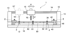
- FIG. 2 is a side view showing a schematic configuration of a machine tool according to an embodiment of the present invention.
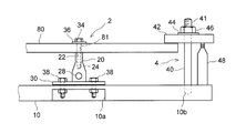
- FIG. 3 is a side view showing a drilling jig and a clamp mechanism according to an embodiment of the present invention.
- FIG. 4 is a side view showing another configuration example of the clamp mechanism.
- the tube sheet of the condenser is illustrated as the plate member 80 to be processed, but the processing object is not limited to this, and a plate in which a plurality of through holes should be formed Any member 80 may be used.
- a large number of through holes 81 and 82 through which the heat transfer pipe penetrates are formed in the tube sheet which is the plate member 80.
- a hole arrangement in which a large number of through holes 81, 82 (or planned formation locations of through holes) are arranged is usually an arrangement of triangular pitch or square pitch, but the drilling method and drilling according to the present embodiment
- the processing jig 2 can be suitably applied to such an arrangement.
- a tube support plate may be processed as the plate member 80 having a hole arrangement similar to the tube plate.
- the hole arrangement which consists of a plurality of through holes including the first through holes 81 and the second through holes 82 is shown by a filled region in the figure.
- a plurality of second through holes 82 are formed in the area except the first through hole 81 in the filled area. Furthermore, in FIG. 1, a clamp position 85 fixed by the clamp mechanism 4 described later is shown on the outer peripheral portion of the plate member 80.
- the machine tool 1 for drilling the plate member 80 includes the bed 10 to which the plate member 80 is fixed, the formation of the first through hole 81, and the plate member 80.
- Jig 2 used for fixing the sheet 10 to the bed 10
- a clamp mechanism 4 used for fixing the plate member 80 to the bed 10
- a hole forming mechanism 12 for forming the through holes 81 and 82 in the plate member 80.
- the bed 10 is used to fix the plate member 80 to be processed. Specifically, the bed 10 is provided with a jig fixing portion 10a to which the drilling jig 2 is fixed, and a clamp fixing portion 10b to which the clamp mechanism 4 is fixed. In addition, a drilling mechanism 12 is disposed on the bed 10. The plate member 80 fixed on the bed 10 is drilled from above by the drilling mechanism 12.
- the drilling mechanism 12 has a longitudinal direction on at least a pair of columns 13 erected on the bed 10, a rail 14 bridged between the at least a pair of columns 13, and the rail 14 (shown in FIGS. 1 and 2).
- the drilling tool 16 is rotated by the tool driving unit 15 and vertically moved in the height direction (the Z direction shown in FIG. 2).
- a high-speed drill or a carbide drill is used as the drilling tool 16.
- the pair of columns 13 may be moved in the depth direction (the Y direction shown in FIG. 1) together with the rail 14, the tool drive unit 15 and the drilling tool 16. Thereby, a through-hole can be formed in the arbitrary positions of the plate member 80 shown in FIG.
- the drilling jig 2 is fixed to the bed 10 at a position corresponding to the first through hole 81, and assists the work of forming a plurality of through holes 81, 82 in the plate member 80.
- the detailed configuration of the drilling jig 2 will be described later.
- the clamp mechanism 4 includes a bolt 40 fixed to the bed 10, a pressure plate 42 attached to the bolt 40, for holding the plate member 80, a nut 46 for fixing the pressure plate 42 in a predetermined position, and a bolt 40. And a jack 48 for supporting the lower surface of the pressing plate 42 on the opposite side to the plate member 42. A washer 44 may be interposed between the pressing plate 42 and the nut 46 in order to prevent damage to the pressing plate 42. Also, instead of the jack 48, an actuator such as a cylinder or a motor may be used. Specifically, the bolt 40 is implanted in the clamp fixing portion 10b of the bed 10 so as to stand vertically. An external thread 41 is formed on the upper end side of the bolt 40.
- the pressing plate 42 is provided with a through hole (not shown), and the upper end side of the bolt 40 passes through the through hole. Furthermore, a washer 44 and a nut 46 are sequentially fitted on the upper end side of the bolt 40, and the nut 46 is screwed onto the male screw 41 of the bolt 40 to move from the pressing plate 42 toward the bed 10 with respect to the plate member 80. A pressing force is applied to fix the pressing plate 42 to the bed 10 side. Further, in order to prevent the holding plate 42 from being inclined, a jack 48 is provided to support the lower surface of the holding plate 42 opposite to the plate member 42 with the bolt 40 interposed therebetween.
- the jacks 48 are adjusted to have substantially the same height as the upper surface of the plate member 80, and the lower surface of the pressing plate 42 opposite to the plate member 42 is supported. Thus, the pressing force can be applied to the plate member 80 while holding the pressing plate 42 in the horizontal direction.
- FIG. 4 another example of the configuration of the clamp mechanism 4 may have a bolt 50 that is detachable from the bed 10.
- Male screws 51 and 52 are formed at both ends of the bolt 50.
- the pressing plate 42, the washer 44 and the nut 46 are fitted on the upper end side of the bolt 50 as in FIG. 3 described above, and the pressing plate 42 is engaged by screwing the upper male screw 51 and the female screw 47 of the nut 46.
- the pressing force is applied to the plate member 80.
- the clamp fixing portion 10c of the bed 10 is formed in a concave shape, and a nut 54 having a T-shaped cross section is accommodated in the clamp fixing portion 10c.
- the nut 54 is fixed so as not to rotate in the clamp fixing portion 10c.
- a female screw 56 is formed on the inner peripheral side of the nut 54 and is screwed with the lower male screw 52 of the bolt 50.
- the bolt 50 can be detachably fixed to the bed 10.
- the clamp mechanism 4 can be installed only at appropriately selected sites.
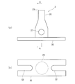
- FIGS. 3, 5 and 6 are a side view of a drilling jig according to an embodiment of the present invention
- FIG. 5 (b) is a bottom view.
- 6 is a cross-sectional view taken along line AA of FIG.
- the drilling jig 2 is configured such that the upper portion is in contact with the base portion 30 configured to be fixable on the bed 10 and the lower surface of the plate member 80, and the lower portion is connected to the base portion 30 And a stand unit 20.
- the drilling jig 2 supports the periphery of the first through hole 81 from below when the first through hole 81 is formed, and has a role of receiving the reaction force of the drilling tool 16, and the second through hole 82.
- the plate member fixing bolt (fixing member) 34 for fixing the plate member 80 is fixed to the bed 10 to increase the rigidity of the plate member 80.
- the first through hole 81 is a through hole formed first among the plurality of through holes, and after the through holes are formed, the plate for the drilling jig 2 is formed via the first through holes 81.
- the member fixing bolt 34 is inserted, and the plate member 80 is fixed.
- the second through hole 82 is a through hole formed in a state where the plate member 80 is fixed to the drilling jig 2 via the first through hole 81.
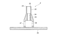
- a clearance hole 22 is formed, into which the tip of the drilling tool 16 penetrating the first through hole 81 of the plate member 80 can be inserted.
- the shape of “clearance hole 22” is not limited as long as it has a size such that a gap is formed between it and the outer shape of drilling tool 16.
- a polygonal hole including a round hole and a rectangular hole It may be holes of various shapes such as.
- an intermediate hollow portion 25 in which a female screw 24 whose valley portion is smaller in diameter than the inner diameter of the first through hole 81 is formed.
- the female screw 24 is configured to be screwed with an external screw formed on the plate member fixing bolt 34, and functions as a locking portion for locking the plate member fixing bolt 34. Furthermore, on the periphery of the clearance hole 22 at the upper end of the stand portion 20, a flat support portion 23 with which the lower surface of the plate member 80 abuts is provided.
- the base portion 30 of the drilling jig 2 is fixed to the jig fixing portion 10 a of the bed 10 by the bolt 38. Thereby, the drilling jig 2 is fixed in a state of being erected on the bed 10.
- the plate member 80 is placed on the support portion 23 of the stand portion 20.
- the drilling tool 16 is inserted into the plate member 80 in a state where the plate member 80 is placed on the stand portion 20, and drilling is performed. Thereby, the reaction force at the time of insertion of the drilling tool 16 can be received by the support portion 23 of the stand portion 20.
- the clearance hole 22 is formed in the upper portion of the stand portion 20, it is possible to prevent the inner surface of the stand portion 20 from being scraped off by the tip end of the drilling tool 16 penetrating the first through hole 81.
- a bolt (plate member fixing bolt) 34 with an external thread formed is inserted into the first through hole 81 from above the plate member 80, and the lower portion of the stand portion 20 is formed.
- the bolt 34 is screwed into the female screw 24 to fix the plate member 80 to the drilling jig 2.
- a washer 36 may be interposed between the head of the bolt 34 and the plate member 80.
- the plate member 80 can be fixed to the bed 10 by screwing the bolt 34 having the male screw formed thereon to the female screw 24 through the first through hole 81 and the clearance hole 22 of the plate member 80. .
- the second through hole 82 is formed by the drilling tool 16 in a state where the plate member 80 is fixed to the drilling jig 2 and the bed 10 via the at least one first through hole 81. Do. At this time, since the plate member 80 is fixed to the drilling jig 2 through at least one first through hole 81, the rigidity of the plate member 80 can be improved, and the plate member 80 can be formed when the second through hole 82 is formed. It can suppress 80 vibrations and bounces. According to the above configuration, it is possible to precisely form the first through holes 81 and the second through holes 82 and to prevent the occurrence of troubles such as breakage in the drilling tool 16.
- a cavity 26 may be formed in the lower portion of the stand 20.
- the hollow portion 26 is provided below the female screw 24 and communicates with the hole in which the female screw 24 is formed.
- chips generated by the drilling process are dropped and stored.
- the hollow portion 26 communicates with the outside through a chip discharge port 27 provided in the base portion 30 or the stand portion 20. With this configuration, the chips accumulated in the hollow portion 26 are discharged to the outside through the chip discharge port 27.
- the base portion 30 extends along a direction orthogonal to the stand portion 20, and the base portion 30 has a tip end of a bolt 38 for fastening the base portion 30 on the bed 10.
- An elongated hole 32 through which the portion can be inserted may be formed along the extension direction of the base portion 30.
- FIGS. 7 and 8 may be used.
- the jig 2 shown in the above embodiment is provided with the female screw 24 at the middle portion in the vertical axis direction of the stand portion 20, but the first modified example (FIG. 7) and the second modified example (FIG. 7) described below
- the jig 6 shown in 8) is different in that the inner wall of the middle portion of the stand portion 60 has a smooth middle cavity portion 62.
- the other configuration is the same as that of the above-described embodiment, and thus the detailed description of the same configuration is omitted.
- 7 is a cross-sectional view of a drilling jig according to a first modification of the present invention
- FIG. 8 is a cross-sectional view of a drilling jig according to a second modification of the present invention.
- both nut bolts 66 are used as the fixing member as means for fixing the plate member to the jig 6.
- the inner surface of the intermediate cavity 62 is not internally threaded, and the inner diameter of the intermediate cavity 62 is preferably smaller than the inner diameter of the clearance hole and somewhat larger than the outer diameter of the double nut bolt 66.
- the bearing surface of the nut 46 disposed in the cavity 64 abuts against the ceiling surface of the cavity 64 and works on the both nut bolts 66.
- the ceiling surface of the stand portion 60 can support the tensile force.
- the ceiling surface of the hollow portion 64 with which the seat surface of the nut 46 abuts functions as a locking portion for locking the bolt (fixing member) 66 for both nuts.
- the cross section in the horizontal direction of the hollow portion 64 in which the lower portion of the intermediate hollow portion 62 is open is a cross section in which the opening of the intermediate hollow portion 62 can be arranged, various sections such as round holes and polygonal holes including rectangular holes The shape is applicable.
- the nuts 46 used to fasten the two nut bolts 66 the nuts 46 disposed in the hollow portion 64 are temporarily attached by spot welding or the like at a position where the intermediate hollow portion 62 on the ceiling surface of the hollow portion 64 is opened. It may be a structure. According to the configuration of the first modified example shown in FIG. 7, it is not necessary to provide an internal thread portion in the intermediate hollow portion 62, and maintenance is easy.
- the second modified example shown in FIG. 8 is different in that a special bolt 70 and an auxiliary member (wedge 78) are applied in place of the bolt for both nuts as a fixing member shown in the first modified example. That is, as shown in FIG. 8, the point of using the drilling jig 6 is the same as the first modified example, except that the special bolt 70 shown in FIG. 9A is used as the fixing member. There is. A male screw portion 72 is provided on one side in the longitudinal direction of the special bolt 70, and a lower fixing portion 73 is provided on the other side. Both form an integral fixing member together with the main body portion 71.
- the lower fixing portion 73 divides the outer circumference into eight parts and cuts a part of the inner and outer circumferences to form an inverted conical hollow portion 76 in the inner axial direction, and the outer peripheral side has a four-footed overhang portion 74 is formed (cross section B-B).
- each foot of the overhang portion 74 has a spring property that can be elastically deformed in the radial direction of the special bolt 70.
- the overhanging portion 74 is provided with a flange portion 75 which spreads in the radial direction at its end.
- the extension part 74 showed the example of 8 division (4 legs), if it is at least 4 division or more, it will not be restricted to this example.
- the inner peripheral surface of the intermediate hollow portion 62 with which the outer peripheral surface of the overhang portion 74 abuts, and the ceiling surface of the hollow portion 64 with which the flange portion 75 abuts are special bolts (fixing members Functions as a locking portion for locking 70).
- the jig 6 applied to the second modification is similar to the other embodiments and modifications in having the clearance hole 22, the intermediate hollow portion 62 and the hollow portion 64, but the clearance hole 22 and the intermediate hollow portion
- the connecting portion of the portion 62 preferably has a shape such that the inner surface is smoothly connected by an inclined surface or the like.
- the upper end of the clearance hole 22 has a slightly larger diameter
- the lower end opening of the intermediate cavity 62 has a slightly smaller diameter
- the inner surface has a conical surface having a constant inclined surface from the upper end of the clearance hole 22 to the lower end opening of the intermediate cavity 62
- FIG. 9 (b) also shows a conical wedge 78 inserted into the cavity 64.
- the special bolt 70 is inserted into the stand portion 60 from above the plate member 80 through the through hole 81 of the plate member 80 until the collar portion 75 appears in the hollow portion 64.
- the flange portion 75 side of the special bolt 70 is inserted as a head.
- the springability of the overhang portion 74 causes the collar portion 75 to expand in the radial direction of the special bolt.
- the wedge 78 is inserted into the hollow portion 76 formed between the overhanging portions 74 of the special bolts 70 from the hollow portion 64 in the opposite direction.
- the collar portion 75 and the projection portion 74 are further expanded in the radial direction, and the outer peripheral circle (the length between the outer surfaces of the opposing collar portions) of the collar portion 75 formed of four legs It becomes larger than the opening of the part 62.
- the nut 46 at the top of the special bolt 70 is tightened, the upper surface of the horizontal surface of the collar 75 is in close contact with the ceiling surface of the hollow 64.
- the special bolt 70 can be fixed to the stand portion 60 through the collar portion 75, and the plate member 80 can be fixed to the jig 6.
- the drilling method according to one embodiment and each modification will be described in detail.
- a hole arrangement including a plurality of through hole positions is set.
- the through hole position to be the first through hole 81 is selected among the plurality of through hole positions.
- the jig arrangement area of the plate member 80 is divided into a grid by the virtual vertical dividing line 90 in the vertical direction and the virtual horizontal dividing line 92 in the horizontal direction. For example, it divides
- the through hole (including the through hole on the intersection) closest to each intersection of the virtual vertical division line 90 and the virtual horizontal division line 92 is selected, and this is set as the first through hole 81.
- the drilling jig 2 is arranged at substantially equal intervals in the jig arrangement area in the central portion of the plate member 80, the rigidity of the jig arrangement area can be substantially uniformly improved, which is more appropriate. Can be drilled into the
- the drilling jig 2 is fixed on the bed 10 of the machine tool 1. Specifically, at least one jig 2 is positioned on the basis of a processing origin O of the machine tool 1, and at least one jig 2 is fixed on the bed 10 by bolts 38.
- the processing origin O is a processing reference point determined on the machine tool side, and the tool drive unit 15 ′, the drilling tool 16 ′, and the plate member are positioned with reference to this.
- the plate member 80 is placed on at least one jig 2, and the plate member 80 is fixed to the bed 10 by the clamp mechanism 4. At this time, the plate member 80 may be positioned based on the processing origin O, and the plate member 80 may be placed on at least one jig 2. At least one of the jigs 2 is positioned with reference to the machining origin O of the machine tool 1, and the plate member 80 is also positioned with respect to the machining origin O. The two jigs 2 can be arranged with high accuracy.
- the machine tool 1 is operated such that the tip of the drilling tool 16 penetrating the plate member 80 is inserted into the clearance hole 22, and the drilling tool is positioned at a position corresponding to the clearance hole 22 of the plate member 80 A first through hole 81 is formed.
- the plate member 80 is fixed to the bed 10 by the clamp mechanism 4, and the periphery of the first through hole 81 into which the drilling tool 16 is inserted is supported from below by the jig 2. Therefore, even if the plate member 80 is not fixed to the jig 2, the jig 2 can receive a reaction force when the drilling tool 16 is inserted. Further, since the vibration, the jumping up and the like of the plate member 80 can be suppressed, it is possible to form a precise through hole and to prevent the occurrence of troubles such as breakage in the drilling tool 16.
- the plate member fixing bolt 34 is inserted into the first through hole 81, and the plate member 80 is fixed to the at least one jig 2 by the plate member fixing bolt 34.
- the plate member 80 is fixed to the bed 10 side using the first through holes 81 formed earlier among the plurality of through holes, the plate members of the hole arrangement such as the triangular pitch or the square pitch Even 80 can be easily fixed to the bed 10 side.
- the machine tool 1 is operated to form the second through holes 82 other than the first through holes 81 among the plurality of through holes.
- the plate member 80 is fixed to the bed 10 by the plate member fixing bolt 34 inserted into the first through hole 81, so the rigidity of the plate member 80 can be improved. Vibration and bounce of the plate member 80 can be suppressed. Therefore, it is possible to form a precise through hole and to prevent the occurrence of troubles such as breakage in the drilling tool 16.
- the rigidity of the plate member 80 around the second through hole 82 can be freely adjusted by appropriately selecting the position of the first through hole 81, that is, the installation position of the plate member fixing bolt 34.
- the outer peripheral side of the jig arrangement area of at least one jig 2 of the plate member 80 is fixed to the bed 10 by the clamp mechanism 4 May be Further, at the time of forming the first through hole 81, while supporting the jig arrangement area of the plate member 80 from the lower side by at least one jig 2, and fixing the outer peripheral side of the plate member 80 by the clamp mechanism 4, the first through hole 81 may be formed.
- the reaction force of the plate member 80 is received by the jig supporting the jig arrangement area from the lower side while securing the restraint force of the plate member 80 by the clamp mechanism 4 fixing the outer peripheral side of the jig arrangement area. Even when a large number of through holes are located at the central portion of the plate member 80, it is possible to appropriately perform the drilling process.
- the drilling tool 16 may be a carbide drill. As a result, drilling can be performed at high speed, and processing time can be shortened, and a more precise through hole can be formed.
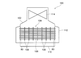
- FIG. 10 is a schematic diagram which shows the structural example of the condenser which concerns on one Embodiment of this invention.
- the condenser 100 condenses the steam used to drive the steam turbine back to water, and supplies it to a boiler or the like that produces steam again as condensed water.
- the condenser 100 used for a thermal power plant, a nuclear power plant or the like is illustrated.
- the condenser 100 has a cylinder 102 forming an outer shape, and a cooling pipe group 104 which is a collection of cooling pipes 106 for cooling steam.
- the body 102 is provided with a water chamber 110 forming a path along which the cooling water circulates with the cooling pipe group 104, and a hot well 112 in which condensed water, which is water condensed from steam, temporarily accumulates.
- a turbine portion 114 of the steam turbine is disposed on the upper portion of the cylinder 102, and a cooling pipe group 104 is disposed below the turbine portion 114.
- a plurality of cooling pipe groups 104 are disposed inside the cylinder 102. Each cooling pipe group 104 extends between the turbine portion 114 and the hot well 112 along the direction in which the rotation axis of the turbine portion 114 extends.
- the cooling pipe group 104 is provided with a plurality of pipe support plates 108 for supporting the cooling pipe 106.
- the tube support plates 108 are spaced apart in the direction in which the cooling tubes 106 extend and are configured to hold an array of cooling tubes 104.
- a tube sheet 80 is provided at the end of the cooling pipe group 104.
- the tube sheet 80 is manufactured using the drilling jig 2 or the drilling method as described above.
- the tube support plate 108 may also be manufactured using the drilling jig or the drilling method according to the present embodiment.
- the through holes 81 and 82 of an arbitrary hole arrangement, and to suppress the vibration, the jump, and the like of the plate member 80 when the drilling tool 16 is inserted.
- the formation of precise through holes 81, 82 is possible, and the occurrence of troubles such as breakage in the drilling tool 16 can be avoided.
Landscapes
- Engineering & Computer Science (AREA)
- Mechanical Engineering (AREA)
- Drilling And Boring (AREA)
- Physics & Mathematics (AREA)
- Thermal Sciences (AREA)
- General Engineering & Computer Science (AREA)
Abstract
Description
また、特許文献2では、管板の下部にスペーサを敷く構成となっており、穴数が少なく四角ピッチ等の単純な穴配列でない限り、穴あけツールとスペーサが干渉するおそれがあり、スペーサの配置が困難となる。したがって、例えば復水器の管板や管支持板等のように穴配列が複雑で多数の貫通穴を有する板部材の穴あけ加工に適用することは難しい。同様に、特許文献3でも、板部材の全幅に亘って吸収部材を配置しているため、板部材の穴配列によってはその適用が困難となる。
さらに、特許文献3では、加工ポイント毎に押圧部材による押圧操作を行う必要があり、加工時間が長くなるという問題や、穴あけ加工時に発生する切粉が板部材と押圧部材の押さえ足との間に挟まる可能性があり、その場合押圧操作に不具合が生じるという問題もある。 On the other hand, only by fixing the periphery of the plate member with a clamp as in
Moreover, in
Furthermore, in patent document 3, it is necessary to perform pressing operation by a pressing member for every processing point, the problem that processing time becomes long, and the chips generated at the time of drilling processing are between a plate member and pressing foot of a pressing member There is also a problem in that there is a problem in that the pressing operation may occur.
なお、本明細書における“クリアランス穴”は、穴あけツールの外形との間に隙間が形成されるようなサイズの穴であればその形状は限定されず、例えば、丸穴、矩形穴を含む多角形穴等の種々の形状の穴であってもよい。 A drilling method according to at least one embodiment of the present invention is a drilling method for forming a plurality of through holes in a plate member using a machine tool having a drilling tool equipped with a carbide drill, and having a clearance hole A first step of fixing at least one jig on a bed of the machine tool, and a second step of mounting the plate member on the at least one jig and fixing the plate member to the bed by a clamp And operating the machine tool such that the tip of the drilling tool that has penetrated the plate member is inserted into the clearance hole, and the plurality of through holes are positioned at positions corresponding to the clearance holes of the plate member. A third step of forming a first through hole, inserting a fixing member into the first through hole, and fixing the plate member to the at least one jig by the
The “clearance hole” in the present specification is not limited in its shape as long as it has a size such that a gap is formed between the hole and the outer shape of the drilling tool. It may be holes of various shapes such as square holes.
この実施形態では、工作機械の加工原点を基準として少なくとも一つの治具を位置決めし、さらにこの加工原点を基準として板部材も位置決めするようにしたので、板部材に対して所定の位置関係で少なくとも一つの治具を高精度に配置することができる。 In some embodiments, in the first step, the at least one jig is positioned with reference to a processing origin of the machine tool, the at least one jig is fixed on the bed, and the second step is performed. Then, the plate member is positioned on the basis of the processing origin and placed on the plate member on the at least one jig.
In this embodiment, at least one jig is positioned on the basis of the processing origin of the machine tool, and the plate member is also positioned on the basis of the processing origin. One jig can be arranged with high accuracy.
このように、治具配置エリアの外周側を固定するクランプによって板部材の拘束力を確保しながら治具配置エリアを下方から支える治具によって板部材の反力を受けるようにしたので、板部材の中央部に多数の貫通穴が位置する場合であっても、適切に穴あけ加工を行うことができる。なお、第1貫通穴および第2貫通穴が配列された領域を、治具配置エリアと呼ぶ。 In some embodiments, in the second step, an outer peripheral side of a jig arrangement area of the at least one jig of the plate members is fixed to the bed by the clamp, and in the third step, the third step is performed The first through hole is formed while supporting the jig arrangement area of the plate member from the lower side by at least one jig and fixing the outer peripheral side of the plate member by the clamp.
As described above, the reaction force of the plate member is received by the jig supporting the jig arrangement area from the lower side while securing the restraint force of the plate member by the clamp that fixes the outer peripheral side of the jig arrangement area. Even in the case where a large number of through holes are located at the central portion of, it is possible to appropriately perform drilling. A region in which the first through holes and the second through holes are arranged is referred to as a jig arrangement area.
これにより、板部材の中央部の治具配置エリアに略均等な間隔で治具が配置されるので、治具配置エリアの板部材の剛性を略均一に向上させることができ、より適切に穴あけ加工を行うことができる。 In some embodiments, of the plurality of through holes, the first through hole divides a jig arrangement area of the plate member into a plurality of grids, and a virtual vertical dividing line in the vertical direction and a virtual virtual dividing line in the horizontal direction. It is a through hole closest to each intersection with the horizontal division line.
Thus, the jigs are arranged at substantially equal intervals in the jig arrangement area at the central portion of the plate member, so that the rigidity of the plate members in the jig arrangement area can be substantially uniformly improved, and drilling can be more appropriately performed. It can be processed.
このように、スタンド部に形成され貫通穴の内径よりも小径である雌ねじに固定部材が係止されるように構成することで、雄ねじが形成された固定部材を、板部材の貫通穴及びクリアランス穴を介して雌ねじに螺合することによって、板部材をベッドに固定することができる。 In some embodiments, the locking portion is a female screw whose valley is smaller than the inner diameter of the through hole and which is screwed to a male screw provided on the fixing member.
As described above, by fixing the fixing member to the female screw formed in the stand portion and having a diameter smaller than the inner diameter of the through hole, the fixing member formed with the male screw can be used as the through hole and clearance of the plate member. The plate member can be fixed to the bed by screwing the female screw through the hole.
このように、スタンド部の上部にクリアランス穴が形成されているので、貫通穴を貫通した穴あけツールの先端部によりスタンド部が削られることを阻止できる。 In some embodiments, the clearance hole has an inner diameter larger than the inner diameter of the through hole.
Thus, since the clearance hole is formed in the upper part of the stand part, it is possible to prevent the stand part from being scraped by the tip of the drilling tool that penetrates the through hole.
このように、スタンド部の下部に、穴あけ加工によって発生した切粉を溜める空洞部を設けるとともに、スタンド部又はベース部に、空洞部に溜まった切粉を排出する切粉排出口を設けるようにしたので、穴あけ加工によって発生した切粉を穴あけ加工用治具から外部へ円滑に排出することができる。 In some embodiments, in the lower portion of the stand portion, a hollow portion is formed below the female screw, and is in communication with the hollow portion, and chips generated by processing the through hole in the plate member The chip | tip discharge port for discharging | emitting is provided in the said stand part or the said base part.
As described above, the lower part of the stand portion is provided with a hollow portion for storing chips generated by drilling, and the stand portion or the base portion is provided with a chip discharge port for discharging chips accumulated in the hollow portion. Thus, chips generated by drilling can be smoothly discharged from the drilling jig to the outside.
これにより、ベース部に形成されたスリット又は長穴の長手方向に対する固定部材の位置を調整することによって、ベース部に対する穴あけ加工用治具の取り付け位置を微調整できる。 In some embodiments, the base portion extends in a direction orthogonal to the stand portion, and the base portion includes a tip of a fastening member for fastening the base portion on the bed. A slit or an elongated hole through which the part can be inserted is formed along the extending direction of the base part.
Thus, by adjusting the position of the fixing member with respect to the longitudinal direction of the slit or the elongated hole formed in the base portion, it is possible to finely adjust the mounting position of the drilling jig with respect to the base portion.
以下、本実施形態では、加工対象である板部材80として復水器の管板を例示しているが、加工対象物はこれに限定されるものではなく、複数の貫通穴を形成すべき板部材80であれば何れであってもよい。 FIG. 1 is a plan view schematically showing a tube sheet of a condenser to which an embodiment of the present invention is applied. FIG. 2 is a side view showing a schematic configuration of a machine tool according to an embodiment of the present invention. FIG. 3 is a side view showing a drilling jig and a clamp mechanism according to an embodiment of the present invention. FIG. 4 is a side view showing another configuration example of the clamp mechanism.
Hereinafter, in the present embodiment, the tube sheet of the condenser is illustrated as the
具体的には、ボルト40は、鉛直方向に立設するように、ベッド10のクランプ固定部10bに植え込まれている。ボルト40の上端側には雄ねじ41が形成されている。押さえ板42には不図示の貫通穴が設けられており、この貫通穴にボルト40の上端側が貫通している。さらに、ボルト40の上端側には、ワッシャ44、ナット46が順に嵌め込まれ、ナット46をボルト40の雄ねじ41に螺合することによって、押さえ板42から板部材80に対してベッド10側に向かう押圧力を付与し、押さえ板42をベッド10側に固定する。また、押さえ板42が傾くことを防止する目的で、ボルト40を挟んで板部材42とは反対側の押さえ板42の下面を支持するジャッキ48が設けられている。このジャッキ48を、板部材80の上面と略同一高さとなるように調整し、板部材42とは反対側の押さえ板42の下面を支持する。これにより、押さえ板42を水平方向に保持しながら板部材80に押圧力を付与することができる。 The
Specifically, the
一実施形態において、穴あけ加工用治具2は、ベッド10上に固定可能に構成されたベース部30と、板部材80の下面に上部が当接するように構成され、ベース部30に下部が接続されるスタンド部20とを備える。そして、穴あけ加工用治具2は、第1貫通穴81の形成時には、第1貫通穴81の周囲を下方から支持し、穴あけツール16の反力を受ける役割を有し、第2貫通穴82の形成時には、板部材80の固定用の板部材固定用ボルト(固定部材)34によりベッド10に固定し、板部材80の剛性を上げる役割を有する。なお、第1貫通穴81は、複数の貫通穴のうち先に形成される貫通穴であって、貫通穴の形成後には、この第1貫通穴81を介して穴あけ加工用治具2に板部材固定用ボルト34が挿入され、板部材80が固定される。第2貫通穴82は、第1貫通穴81を介して穴あけ加工用治具2に板部材80が固定された状態で形成される貫通穴である。 Here, the configuration of the
In one embodiment, the
上記構成によって、精密な第1貫通穴81及び第2貫通穴82の形成が可能となるとともに穴あけツール16に折損等トラブルが発生することを防止できる。 At the time of formation of the second through
According to the above configuration, it is possible to precisely form the first through
予め、加工対象となる板部材80には、複数の貫通穴位置からなる穴配列が設定されている。
まず、複数の貫通穴位置のうち第1貫通穴81となる貫通穴位置を選択する。具体的には、図1に示すように、板部材80の治具配置エリアを、縦方向の仮想縦分割線90及び横方向の仮想横分割線92によって格子状に分割する。例えば、横方向、縦方向共に等間隔の約400mmピッチで分割する。そして、仮想縦分割線90と仮想横分割線92の各交点に最も近い貫通穴(交点上の貫通穴を含む)を選択し、これを第1貫通穴81に設定する。これにより、板部材80の中央部の治具配置エリアに略均等な間隔で穴あけ加工用治具2が配置されるので、治具配置エリアの剛性を略均一に向上させることができ、より適切に穴あけ加工を行うことができる。 Hereinafter, the drilling method according to one embodiment and each modification will be described in detail.
In advance, in the
First, the through hole position to be the first through
復水器100は、蒸気タービンの駆動に用いられた蒸気を凝縮して水に戻し、復水として再び蒸気を生成するボイラなどに供給するものである。本実施形態では、例えば、火力発電プラントや原子力発電プラント等に用いられる復水器100を例示している。 Next, a
The
また、冷却管群104には、冷却管106を支持する複数の管支持板108が設けられている。管支持板108は、冷却管106が延設される方向に間隔をあけて配置され、冷却管群104の配列を保持するように構成される。
さらに、冷却管群104の端部には、管板80が設けられている。管板80は、上述したような穴あけ加工用治具2又は穴あけ加工方法を用いて作製されたものである。なお、管板80の他に管支持板108も、本実施形態に係る穴あけ加工用治具又は穴あけ加工方法を用いて作製されてもよい。 A plurality of
The
Furthermore, at the end of the
2,6 穴あけ加工用治具
4 クランプ機構
10 ベッド
10a 治具固定部
10b,10c クランプ固定部
12 穴あけ機構
13 支柱
14 レール
15 ツール駆動部
16 穴あけツール
20,60,70 スタンド部
22,62 クリアランス穴
23 支持部
24,56,64 雌ねじ
26,66 空洞部
27,67 切粉排出口
30 ベース部
32 長穴
34 板部材固定用ボルト(固定部材)
62 中間空洞部
66 両ナット用ボルト(固定部材)
70 特殊ボルト(固定部材)
38,40,50 ボルト(締結部材)
36,44 ワッシャ
41,51,52 雄ねじ
42 押さえ板
46,54 ナット
48 ジャッキ
47、56 雌ねじ
100 復水器
102 胴
104 冷却管群
106 冷却管
108 管支持板
110 水室
112 ホットウェル
114 タービン部
62
70 Special bolt (fixed member)
38, 40, 50 bolt (fastening member)
36, 44
Claims (10)
- 超硬ドリルを備えた穴あけツールを有する工作機械を用いて板部材に複数の貫通穴を形成する穴あけ加工方法であって、
クリアランス穴を有する少なくとも一つの治具を前記工作機械のベッド上に固定する第1ステップと、
前記少なくとも一つの治具上に前記板部材を載置し、前記板部材をクランプで前記ベッドに固定する第2ステップと、
前記板部材を貫通した前記穴あけツールの先端部が前記クリアランス穴に挿入されるように前記工作機械を動作させ、前記板部材の前記クリアランス穴に対応する位置に前記複数の貫通穴のうち第1貫通穴を形成する第3ステップと、
前記第1貫通穴に固定部材を挿通し、該固定部材によって前記板部材を前記少なくとも一つの治具に固定する第4ステップと、
前記第4ステップの後、前記工作機械を動作させて前記複数の貫通穴のうち前記第1貫通穴以外の第2貫通穴を形成する第5ステップとを備えることを特徴とする穴あけ加工方法。 A drilling method for forming a plurality of through holes in a plate member using a machine tool having a drilling tool equipped with a carbide drill, comprising:
A first step of fixing at least one jig having a clearance hole on the bed of the machine tool;
Placing the plate member on the at least one jig and fixing the plate member to the bed with a clamp;
The machine tool is operated such that the tip of the drilling tool that has penetrated the plate member is inserted into the clearance hole, and the first of the plurality of through holes is positioned at a position corresponding to the clearance hole of the plate member. A third step of forming a through hole;
A fourth step of inserting a fixing member into the first through hole and fixing the plate member to the at least one jig by the fixing member;
A drilling method comprising: a fifth step of operating the machine tool after the fourth step to form a second through hole other than the first through hole among the plurality of through holes. - 前記第1ステップでは、前記工作機械の加工原点を基準として前記少なくとも一つの治具を位置決めし、前記少なくとも一つの治具を前記ベッド上に固定し、
前記第2ステップでは、前記加工原点を基準として前記板部材を位置決めし、前記少なくとも一つの治具上に前記板部材に載置することを特徴とする請求項1に記載の穴あけ加工方法。 In the first step, the at least one jig is positioned with reference to a processing origin of the machine tool, and the at least one jig is fixed on the bed.
The drilling method according to claim 1, wherein in the second step, the plate member is positioned on the basis of the processing origin, and the plate member is placed on the plate member on the at least one jig. - 前記第2ステップでは、前記板部材のうち、前記少なくとも一つの治具の治具配置エリアの外周側を前記クランプで前記ベッドに固定し、
前記第3ステップでは、前記少なくとも一つの治具によって前記板部材の前記治具配置エリアを下方から支えるとともに、前記クランプによって前記板部材の外周側を固定しながら前記第1貫通穴を形成することを特徴とする請求項1又は2に記載の穴あけ加工方法。 In the second step, the outer peripheral side of the jig arrangement area of the at least one jig among the plate members is fixed to the bed by the clamp,
In the third step, the first through hole is formed while supporting the jig arrangement area of the plate member from below by the at least one jig and fixing the outer peripheral side of the plate member by the clamp. The drilling method according to claim 1 or 2, characterized in that - 前記第1貫通穴は、前記複数の貫通穴のうち、前記板部材の前記治具配置エリアを複数の格子に分割する縦方向の仮想縦分割線と横方向の仮想横分割線との各交点に最も近い貫通穴であることを特徴とする請求項3に記載の穴あけ加工方法。 Each of the first through holes is an intersection point of a vertical vertical dividing line in the vertical direction and a virtual horizontal dividing line in the horizontal direction that divides the jig arrangement area of the plate member into a plurality of grids among the plurality of through holes. The method according to claim 3, wherein the through hole is the closest to the through hole.
- 穴あけツールを有する工作機械を用いた板部材への複数の貫通穴の形成作業を補助するための穴あけ加工用治具であって、
前記工作機械のベッド上に固定可能に構成されたベース部と、
前記板部材の下面に上部が当接するように構成され、前記ベース部に下部が接続されるスタンド部と、を備え、
前記スタンド部の前記上部には、前記貫通穴を貫通した前記穴あけツールの先端部が挿入可能なクリアランス穴が形成されており、
前記クリアランス穴の下方において、前記貫通穴及び前記クリアランス穴に挿通された前記板部材の固定用の固定部材を係止するための係止部が設けられたことを特徴とする穴あけ加工用治具。 A drilling jig for assisting a forming operation of a plurality of through holes in a plate member using a machine tool having a drilling tool, the drilling jig comprising:
A base portion configured to be fixed on a bed of the machine tool;
And a stand portion configured such that an upper portion is in contact with a lower surface of the plate member, and a lower portion is connected to the base portion;
In the upper portion of the stand portion, a clearance hole is formed, into which the tip of the drilling tool penetrating the through hole can be inserted;
Under the clearance hole, there is provided a locking portion for locking a fixing member for fixing the plate member inserted into the through hole and the clearance hole. . - 前記係止部は、谷部が前記貫通穴の内径よりも小径であり、前記固定部材に設けられた雄ねじに螺合する雌ねじが形成されていることを特徴とする請求項5に記載の穴あけ加工用治具。 The drilling according to claim 5, wherein the locking portion has a valley portion smaller in diameter than an inner diameter of the through hole, and is formed with a female screw which is screwed to a male screw provided on the fixing member. Processing jig.
- 前記クリアランス穴は、前記貫通穴の内径より大きい内径を有することを特徴とする請求項5又は6に記載の穴あけ加工用治具。 The drilling jig according to claim 5 or 6, wherein the clearance hole has an inner diameter larger than the inner diameter of the through hole.
- 前記係止部の下方には空洞部が設けられており、
前記空洞部には、
前記空洞部に連通し、前記板部材への前記貫通穴の加工によって生じる切粉を排出するための切粉排出口が設けられたことを特徴とする請求項5に記載の穴あけ加工用治具。 A hollow portion is provided below the locking portion,
In the hollow portion,
The drilling jig according to claim 5, further comprising a chip discharge port communicating with the hollow portion and discharging a chip generated by processing the through hole into the plate member. . - 前記ベース部は、前記スタンド部に直交する方向に沿って延在しており、
前記ベース部には、前記ベース部を前記ベッド上に締結するための締結部材の先端部が挿通可能なスリット又は長穴が前記ベース部の延在方向に沿って形成されていることを特徴とする請求項5乃至8の何れか一項に記載の穴あけ加工用治具。 The base portion extends along a direction orthogonal to the stand portion,
A slit or an elongated hole through which a tip of a fastening member for fastening the base on the bed can be formed in the base along a direction in which the base extends. A drilling jig according to any one of claims 5 to 8. - 請求項1乃至4の何れか一項に記載の穴あけ加工方法によって前記貫通穴が形成された前記板部材からなる管板又は管支持板を備えた熱交換器。
The heat exchanger provided with the tube sheet or tube support plate which consists of the said plate member by which the said through-hole was formed by the drilling method as described in any one of Claims 1-4.
Priority Applications (5)
| Application Number | Priority Date | Filing Date | Title |
|---|---|---|---|
| KR1020157012765A KR101704321B1 (en) | 2013-01-10 | 2013-12-19 | Drilling method, jig for drilling, and heat exchanger |
| CN201380060165.1A CN104812514B (en) | 2013-01-10 | 2013-12-19 | Method of perforation processing, perforation fixture for processing and heat exchanger |
| US14/441,871 US10005134B2 (en) | 2013-01-10 | 2013-12-19 | Drilling method, drilling jig, and heat exchanger |
| EP13871073.6A EP2944405B1 (en) | 2013-01-10 | 2013-12-19 | Drilling method and drilling jig |
| US15/866,976 US10293414B2 (en) | 2013-01-10 | 2018-01-10 | Drilling method, drilling jig, and heat exchanger |
Applications Claiming Priority (2)
| Application Number | Priority Date | Filing Date | Title |
|---|---|---|---|
| JP2013-002746 | 2013-01-10 | ||
| JP2013002746A JP5984684B2 (en) | 2013-01-10 | 2013-01-10 | Drilling method, drilling jig, and heat exchanger |
Related Child Applications (2)
| Application Number | Title | Priority Date | Filing Date |
|---|---|---|---|
| US14/441,871 A-371-Of-International US10005134B2 (en) | 2013-01-10 | 2013-12-19 | Drilling method, drilling jig, and heat exchanger |
| US15/866,976 Division US10293414B2 (en) | 2013-01-10 | 2018-01-10 | Drilling method, drilling jig, and heat exchanger |
Publications (1)
| Publication Number | Publication Date |
|---|---|
| WO2014109200A1 true WO2014109200A1 (en) | 2014-07-17 |
Family
ID=51166859
Family Applications (1)
| Application Number | Title | Priority Date | Filing Date |
|---|---|---|---|
| PCT/JP2013/084070 WO2014109200A1 (en) | 2013-01-10 | 2013-12-19 | Drilling method, jig for drilling, and heat exchanger |
Country Status (6)
| Country | Link |
|---|---|
| US (2) | US10005134B2 (en) |
| EP (1) | EP2944405B1 (en) |
| JP (1) | JP5984684B2 (en) |
| KR (1) | KR101704321B1 (en) |
| CN (1) | CN104812514B (en) |
| WO (1) | WO2014109200A1 (en) |
Cited By (3)
| Publication number | Priority date | Publication date | Assignee | Title |
|---|---|---|---|---|
| US20170231729A1 (en) * | 2014-11-14 | 2017-08-17 | Ivoclar Vivadent Ag | Abutment tool set and device for producing tooth replacements |
| TWI701420B (en) * | 2019-09-11 | 2020-08-11 | 英業達股份有限公司 | Heat sink assembly device and method of the same |
| CN115673378A (en) * | 2022-09-23 | 2023-02-03 | 马鞍山瑞琪机械设备制造有限公司 | Side plate drilling equipment of plate heat exchanger |
Families Citing this family (12)
| Publication number | Priority date | Publication date | Assignee | Title |
|---|---|---|---|---|
| CN105598506A (en) * | 2016-02-26 | 2016-05-25 | 金川集团股份有限公司 | Punching drill jig used for large annular flange |
| CN106272726B (en) * | 2016-10-17 | 2019-04-02 | 乐清市天美贸易有限公司 | A kind of application method of the wood working tool convenient for positioning drilling |
| CN107186511B (en) * | 2017-07-10 | 2019-04-26 | 广东顺事德智能科技有限公司 | Perforating device is used in a kind of production and processing of hinge |
| CN108098343A (en) * | 2017-12-07 | 2018-06-01 | 浙江吉利汽车有限公司 | A kind of hole processing device and hole forming method |
| CN108714706B (en) * | 2018-06-20 | 2024-04-05 | 江苏英杰电子器件有限公司 | Drilling mechanism for chassis radiator processing equipment |
| US10792772B2 (en) | 2018-07-17 | 2020-10-06 | Denso International America, Inc. | Heat exchanger replacement mounting pin and drill jig |
| CN112296406B (en) * | 2019-08-02 | 2022-07-29 | 中国航天标准化研究所 | Bolt preprocessor |
| CN110893481B (en) * | 2019-12-09 | 2020-10-30 | 中航沈飞民用飞机有限责任公司 | Porous hole returning drilling die and manufacturing method thereof |
| KR102228074B1 (en) * | 2020-10-26 | 2021-03-15 | 박진성 | Hole forming device |
| CN112658324A (en) * | 2020-12-17 | 2021-04-16 | 贵州凯星液力传动机械有限公司 | Machining device and machining method for oblique small holes in step roots of shaft parts |
| CA3121685A1 (en) * | 2021-06-09 | 2022-12-09 | Larry Whiteway | System and method for installing a floating shelf |
| KR102371975B1 (en) * | 2021-08-05 | 2022-03-07 | 김근수 | Clamping device |
Citations (7)
| Publication number | Priority date | Publication date | Assignee | Title |
|---|---|---|---|---|
| JPS6412711A (en) | 1987-07-07 | 1989-01-17 | Murata Manufacturing Co | Chip type resonator |
| JPH0160815U (en) * | 1987-10-15 | 1989-04-18 | ||
| JPH01320223A (en) | 1988-06-23 | 1989-12-26 | Furukawa Electric Co Ltd:The | Synthesizing method for oxide superconductor |
| JPH05116013A (en) * | 1991-10-25 | 1993-05-14 | Hitachi Seiko Ltd | Printed board drilling machine |
| JPH05146905A (en) | 1991-11-28 | 1993-06-15 | Mitsubishi Heavy Ind Ltd | Method and device for boring pipe hole on pipe plate |
| JPH07234092A (en) * | 1994-02-19 | 1995-09-05 | Mishima Kosan Co Ltd | Pipe plate for heat exchanger |
| JP2009519138A (en) * | 2005-12-16 | 2009-05-14 | エアバス・ユ―ケ―・リミテッド | Fastener assembly |
Family Cites Families (36)
| Publication number | Priority date | Publication date | Assignee | Title |
|---|---|---|---|---|
| DE359808C (en) * | 1922-09-26 | Alfred Mothes | Drilling device with drill bush attached to the workpiece | |
| US652251A (en) * | 1898-11-21 | 1900-06-26 | William Cunningham | Reaming and boring tool. |
| US724116A (en) * | 1902-11-20 | 1903-03-31 | Henry A Maley | Plate-holder for printing-presses. |
| US2208480A (en) * | 1938-09-24 | 1940-07-16 | Smith Willis | Automatic drilling jig |
| US2392804A (en) * | 1941-10-13 | 1946-01-15 | Lockheed Aircraft Corp | Method of making molded drill jigs |
| US2351243A (en) * | 1942-10-13 | 1944-06-13 | Vetter Johannas | Combination drill guide and clamp |
| US2388320A (en) * | 1943-07-19 | 1945-11-06 | Gardiner Linzie Artemas | Machine tool attachment |
| US2384071A (en) * | 1943-11-23 | 1945-09-04 | Samuel R Boyer | Instrument for locating and spacing bored holes |
| US2920509A (en) * | 1955-04-25 | 1960-01-12 | Rohr Aircraft Corp | Drill bushing and jig |
| US2915789A (en) * | 1957-07-25 | 1959-12-08 | Western Electric Co | Method of making drill jigs |
| US3148562A (en) * | 1962-08-30 | 1964-09-15 | Thomas J Moss | Alignment tool for drill or tapping bits |
| GB1227732A (en) * | 1967-04-14 | 1971-04-07 | ||
| US4005945A (en) * | 1975-09-25 | 1977-02-01 | David Gutman | Drill guide |
| JPS5710139A (en) | 1980-06-23 | 1982-01-19 | Konishiroku Photo Ind Co Ltd | Packed photographic product |
| DE3410130C1 (en) * | 1984-03-20 | 1985-10-10 | Philips Patentverwaltung Gmbh, 2000 Hamburg | Workpiece carrier for printed circuit boards |
| US4679969A (en) * | 1986-04-07 | 1987-07-14 | Rockwell International Corporation | Positive feed drill clamp system |
| JPS6460815A (en) | 1987-08-31 | 1989-03-07 | Nec Corp | Magnetic memory body |
| ATE148385T1 (en) * | 1992-07-06 | 1997-02-15 | Heinz Kisslig | INTERMEDIATE ELEMENT FOR CLAMPING DEVICES ON PERFORATED PLATES |
| JP2727875B2 (en) | 1992-07-09 | 1998-03-18 | 株式会社日立製作所 | Internal pump |
| DE19800097A1 (en) * | 1997-01-31 | 1998-08-06 | Mitsubishi Materials Corp | Manufacturing procedure for cutting tool |
| US6022009A (en) * | 1997-05-09 | 2000-02-08 | Northrop Grumman Corporation | Top load threaded bolt assembly |
| AU685381B3 (en) * | 1997-08-13 | 1998-01-15 | Anthony Desmond Fenelon | Dowel jig |
| JPH11320223A (en) | 1998-05-08 | 1999-11-24 | Kurimoto Ltd | Method for boring plate and boring work machine therefor |
| JP3663479B2 (en) * | 1998-10-07 | 2005-06-22 | オークマ株式会社 | Workpiece positioning jig for machine tools |
| JP4415485B2 (en) * | 2000-11-14 | 2010-02-17 | 三菱マテリアル株式会社 | Small drill |
| US7018144B2 (en) * | 2002-07-02 | 2006-03-28 | Mitsubishi Materials Corporation | Drill |
| WO2008092111A2 (en) * | 2007-01-26 | 2008-07-31 | Jm Electronics Ltd. Llc | Drivers and methods for driving a load |
| CA2635824A1 (en) | 2007-06-29 | 2008-12-29 | Quickmill Inc. | Work piece support |
| US8292551B2 (en) * | 2008-05-01 | 2012-10-23 | Lockheed Martin Corporation | System, method and apparatus for removing failed fasteners |
| DE202009005279U1 (en) * | 2009-09-15 | 2011-02-03 | Wolfcraft Gmbh | Drilling or marking gauge |
| US8770567B2 (en) | 2009-10-06 | 2014-07-08 | Quickmill Inc. | Cushioned support platform |
| US8926240B2 (en) * | 2010-07-23 | 2015-01-06 | Zagar Inc. | End effector |
| CN201862818U (en) * | 2010-10-26 | 2011-06-15 | 南京数控机床有限公司 | Positioning and guiding device for multidirectional drilling |
| CN201862819U (en) * | 2010-11-22 | 2011-06-15 | 杭州九龙机械制造有限公司 | Special rotary fixture for drilling holes on flywheel shells of automobiles |
| JPWO2012114641A1 (en) * | 2011-02-23 | 2014-07-07 | 京セラ株式会社 | Cutting tool and manufacturing method thereof |
| KR101127792B1 (en) | 2011-09-28 | 2012-03-23 | 윤재호 | Plate structure for jig installing of machine tools |
-
2013
- 2013-01-10 JP JP2013002746A patent/JP5984684B2/en active Active
- 2013-12-19 KR KR1020157012765A patent/KR101704321B1/en active IP Right Grant
- 2013-12-19 US US14/441,871 patent/US10005134B2/en active Active
- 2013-12-19 WO PCT/JP2013/084070 patent/WO2014109200A1/en active Application Filing
- 2013-12-19 EP EP13871073.6A patent/EP2944405B1/en active Active
- 2013-12-19 CN CN201380060165.1A patent/CN104812514B/en active Active
-
2018
- 2018-01-10 US US15/866,976 patent/US10293414B2/en active Active
Patent Citations (7)
| Publication number | Priority date | Publication date | Assignee | Title |
|---|---|---|---|---|
| JPS6412711A (en) | 1987-07-07 | 1989-01-17 | Murata Manufacturing Co | Chip type resonator |
| JPH0160815U (en) * | 1987-10-15 | 1989-04-18 | ||
| JPH01320223A (en) | 1988-06-23 | 1989-12-26 | Furukawa Electric Co Ltd:The | Synthesizing method for oxide superconductor |
| JPH05116013A (en) * | 1991-10-25 | 1993-05-14 | Hitachi Seiko Ltd | Printed board drilling machine |
| JPH05146905A (en) | 1991-11-28 | 1993-06-15 | Mitsubishi Heavy Ind Ltd | Method and device for boring pipe hole on pipe plate |
| JPH07234092A (en) * | 1994-02-19 | 1995-09-05 | Mishima Kosan Co Ltd | Pipe plate for heat exchanger |
| JP2009519138A (en) * | 2005-12-16 | 2009-05-14 | エアバス・ユ―ケ―・リミテッド | Fastener assembly |
Cited By (4)
| Publication number | Priority date | Publication date | Assignee | Title |
|---|---|---|---|---|
| US20170231729A1 (en) * | 2014-11-14 | 2017-08-17 | Ivoclar Vivadent Ag | Abutment tool set and device for producing tooth replacements |
| TWI701420B (en) * | 2019-09-11 | 2020-08-11 | 英業達股份有限公司 | Heat sink assembly device and method of the same |
| CN115673378A (en) * | 2022-09-23 | 2023-02-03 | 马鞍山瑞琪机械设备制造有限公司 | Side plate drilling equipment of plate heat exchanger |
| CN115673378B (en) * | 2022-09-23 | 2023-07-18 | 马鞍山瑞琪机械设备制造有限公司 | Side plate drilling equipment of plate heat exchanger |
Also Published As
| Publication number | Publication date |
|---|---|
| EP2944405A1 (en) | 2015-11-18 |
| EP2944405A4 (en) | 2016-08-17 |
| KR20150070337A (en) | 2015-06-24 |
| KR101704321B1 (en) | 2017-02-07 |
| JP5984684B2 (en) | 2016-09-06 |
| EP2944405B1 (en) | 2019-11-27 |
| CN104812514A (en) | 2015-07-29 |
| US10005134B2 (en) | 2018-06-26 |
| CN104812514B (en) | 2017-03-08 |
| US10293414B2 (en) | 2019-05-21 |
| US20150314376A1 (en) | 2015-11-05 |
| US20180147640A1 (en) | 2018-05-31 |
| JP2014133285A (en) | 2014-07-24 |
Similar Documents
| Publication | Publication Date | Title |
|---|---|---|
| WO2014109200A1 (en) | Drilling method, jig for drilling, and heat exchanger | |
| JP2014133285A5 (en) | ||
| CN200995336Y (en) | Clamp for borehole | |
| EP3156159B1 (en) | Valve seat machining device, and valve seat machining method using said valve seat machining device | |
| KR101745936B1 (en) | Jig set for machining propeller | |
| JP4831825B2 (en) | Multi-axis machining equipment | |
| EP3162477A1 (en) | Valve seat machining device, and valve seat machining method using said valve seat machining device | |
| JP2007283314A (en) | Wire drawing device | |
| JP2006218567A (en) | Workpiece positioning device | |
| KR101127792B1 (en) | Plate structure for jig installing of machine tools | |
| CN110666439B (en) | Inner support device and method for preventing deformation of cylinder outer part during welding and heat treatment | |
| US20170292584A1 (en) | Damping apparatus | |
| AU2011326881B9 (en) | Method and device for locking a support ring to a scaffolding column | |
| CN102896532A (en) | Clamp | |
| CN214322644U (en) | Tapping clamp | |
| CN210335198U (en) | Thin-wall cylindrical workpiece machining tool | |
| EP3315249B1 (en) | Work positioner | |
| CN213997877U (en) | Handle processing tool | |
| CN105290675A (en) | Assembly welding template structure of steam cooling separator and steam cooling separator device | |
| JP6920109B2 (en) | Seismic retrofitting method | |
| CN221560565U (en) | Gate valve body horizontal drilling machine processing frock | |
| JP2006159374A (en) | Machine tool with linear guide device, and linear guide changing method | |
| CN101879617B (en) | Method for drilling steam generator heat exchange tube supporting plate | |
| CN114215615B (en) | Damping mounting base of power plant steam turbine and application method thereof | |
| CN220718101U (en) | Frame with shape structure of preapring for an unfavorable turn of events |
Legal Events
| Date | Code | Title | Description |
|---|---|---|---|
| 121 | Ep: the epo has been informed by wipo that ep was designated in this application |
Ref document number: 13871073 Country of ref document: EP Kind code of ref document: A1 |
|
| WWE | Wipo information: entry into national phase |
Ref document number: 2013871073 Country of ref document: EP |
|
| WWE | Wipo information: entry into national phase |
Ref document number: 14441871 Country of ref document: US |
|
| ENP | Entry into the national phase |
Ref document number: 20157012765 Country of ref document: KR Kind code of ref document: A |
|
| NENP | Non-entry into the national phase |
Ref country code: DE |