WO2014109164A1 - 微細構造転写装置及び微細構造転写方法 - Google Patents
微細構造転写装置及び微細構造転写方法 Download PDFInfo
- Publication number
- WO2014109164A1 WO2014109164A1 PCT/JP2013/083195 JP2013083195W WO2014109164A1 WO 2014109164 A1 WO2014109164 A1 WO 2014109164A1 JP 2013083195 W JP2013083195 W JP 2013083195W WO 2014109164 A1 WO2014109164 A1 WO 2014109164A1
- Authority
- WO
- WIPO (PCT)
- Prior art keywords
- transfer
- belt
- roller
- shaped mold
- peeling
- Prior art date
- Legal status (The legal status is an assumption and is not a legal conclusion. Google has not performed a legal analysis and makes no representation as to the accuracy of the status listed.)
- Ceased
Links
Images


Classifications
-
- B—PERFORMING OPERATIONS; TRANSPORTING
- B29—WORKING OF PLASTICS; WORKING OF SUBSTANCES IN A PLASTIC STATE IN GENERAL
- B29C—SHAPING OR JOINING OF PLASTICS; SHAPING OF MATERIAL IN A PLASTIC STATE, NOT OTHERWISE PROVIDED FOR; AFTER-TREATMENT OF THE SHAPED PRODUCTS, e.g. REPAIRING
- B29C59/00—Surface shaping of articles, e.g. embossing; Apparatus therefor
- B29C59/02—Surface shaping of articles, e.g. embossing; Apparatus therefor by mechanical means, e.g. pressing
- B29C59/04—Surface shaping of articles, e.g. embossing; Apparatus therefor by mechanical means, e.g. pressing using rollers or endless belts
-
- B—PERFORMING OPERATIONS; TRANSPORTING
- B29—WORKING OF PLASTICS; WORKING OF SUBSTANCES IN A PLASTIC STATE IN GENERAL
- B29C—SHAPING OR JOINING OF PLASTICS; SHAPING OF MATERIAL IN A PLASTIC STATE, NOT OTHERWISE PROVIDED FOR; AFTER-TREATMENT OF THE SHAPED PRODUCTS, e.g. REPAIRING
- B29C35/00—Heating, cooling or curing, e.g. crosslinking or vulcanising; Apparatus therefor
- B29C35/02—Heating or curing, e.g. crosslinking or vulcanizing during moulding, e.g. in a mould
-
- B—PERFORMING OPERATIONS; TRANSPORTING
- B29—WORKING OF PLASTICS; WORKING OF SUBSTANCES IN A PLASTIC STATE IN GENERAL
- B29C—SHAPING OR JOINING OF PLASTICS; SHAPING OF MATERIAL IN A PLASTIC STATE, NOT OTHERWISE PROVIDED FOR; AFTER-TREATMENT OF THE SHAPED PRODUCTS, e.g. REPAIRING
- B29C35/00—Heating, cooling or curing, e.g. crosslinking or vulcanising; Apparatus therefor
- B29C35/02—Heating or curing, e.g. crosslinking or vulcanizing during moulding, e.g. in a mould
- B29C35/08—Heating or curing, e.g. crosslinking or vulcanizing during moulding, e.g. in a mould by wave energy or particle radiation
- B29C35/0805—Heating or curing, e.g. crosslinking or vulcanizing during moulding, e.g. in a mould by wave energy or particle radiation using electromagnetic radiation
-
- B—PERFORMING OPERATIONS; TRANSPORTING
- B29—WORKING OF PLASTICS; WORKING OF SUBSTANCES IN A PLASTIC STATE IN GENERAL
- B29C—SHAPING OR JOINING OF PLASTICS; SHAPING OF MATERIAL IN A PLASTIC STATE, NOT OTHERWISE PROVIDED FOR; AFTER-TREATMENT OF THE SHAPED PRODUCTS, e.g. REPAIRING
- B29C35/00—Heating, cooling or curing, e.g. crosslinking or vulcanising; Apparatus therefor
- B29C35/16—Cooling
-
- B—PERFORMING OPERATIONS; TRANSPORTING
- B29—WORKING OF PLASTICS; WORKING OF SUBSTANCES IN A PLASTIC STATE IN GENERAL
- B29C—SHAPING OR JOINING OF PLASTICS; SHAPING OF MATERIAL IN A PLASTIC STATE, NOT OTHERWISE PROVIDED FOR; AFTER-TREATMENT OF THE SHAPED PRODUCTS, e.g. REPAIRING
- B29C37/00—Component parts, details, accessories or auxiliary operations, not covered by group B29C33/00 or B29C35/00
- B29C37/0003—Discharging moulded articles from the mould
-
- B—PERFORMING OPERATIONS; TRANSPORTING
- B29—WORKING OF PLASTICS; WORKING OF SUBSTANCES IN A PLASTIC STATE IN GENERAL
- B29C—SHAPING OR JOINING OF PLASTICS; SHAPING OF MATERIAL IN A PLASTIC STATE, NOT OTHERWISE PROVIDED FOR; AFTER-TREATMENT OF THE SHAPED PRODUCTS, e.g. REPAIRING
- B29C35/00—Heating, cooling or curing, e.g. crosslinking or vulcanising; Apparatus therefor
- B29C35/02—Heating or curing, e.g. crosslinking or vulcanizing during moulding, e.g. in a mould
- B29C2035/0211—Heating or curing, e.g. crosslinking or vulcanizing during moulding, e.g. in a mould resistance heating
-
- B—PERFORMING OPERATIONS; TRANSPORTING
- B29—WORKING OF PLASTICS; WORKING OF SUBSTANCES IN A PLASTIC STATE IN GENERAL
- B29C—SHAPING OR JOINING OF PLASTICS; SHAPING OF MATERIAL IN A PLASTIC STATE, NOT OTHERWISE PROVIDED FOR; AFTER-TREATMENT OF THE SHAPED PRODUCTS, e.g. REPAIRING
- B29C35/00—Heating, cooling or curing, e.g. crosslinking or vulcanising; Apparatus therefor
- B29C35/02—Heating or curing, e.g. crosslinking or vulcanizing during moulding, e.g. in a mould
- B29C35/08—Heating or curing, e.g. crosslinking or vulcanizing during moulding, e.g. in a mould by wave energy or particle radiation
- B29C35/0805—Heating or curing, e.g. crosslinking or vulcanizing during moulding, e.g. in a mould by wave energy or particle radiation using electromagnetic radiation
- B29C2035/0811—Heating or curing, e.g. crosslinking or vulcanizing during moulding, e.g. in a mould by wave energy or particle radiation using electromagnetic radiation using induction
-
- B—PERFORMING OPERATIONS; TRANSPORTING
- B29—WORKING OF PLASTICS; WORKING OF SUBSTANCES IN A PLASTIC STATE IN GENERAL
- B29C—SHAPING OR JOINING OF PLASTICS; SHAPING OF MATERIAL IN A PLASTIC STATE, NOT OTHERWISE PROVIDED FOR; AFTER-TREATMENT OF THE SHAPED PRODUCTS, e.g. REPAIRING
- B29C35/00—Heating, cooling or curing, e.g. crosslinking or vulcanising; Apparatus therefor
- B29C35/02—Heating or curing, e.g. crosslinking or vulcanizing during moulding, e.g. in a mould
- B29C35/08—Heating or curing, e.g. crosslinking or vulcanizing during moulding, e.g. in a mould by wave energy or particle radiation
- B29C35/0805—Heating or curing, e.g. crosslinking or vulcanizing during moulding, e.g. in a mould by wave energy or particle radiation using electromagnetic radiation
- B29C2035/0822—Heating or curing, e.g. crosslinking or vulcanizing during moulding, e.g. in a mould by wave energy or particle radiation using electromagnetic radiation using IR radiation
-
- B—PERFORMING OPERATIONS; TRANSPORTING
- B29—WORKING OF PLASTICS; WORKING OF SUBSTANCES IN A PLASTIC STATE IN GENERAL
- B29C—SHAPING OR JOINING OF PLASTICS; SHAPING OF MATERIAL IN A PLASTIC STATE, NOT OTHERWISE PROVIDED FOR; AFTER-TREATMENT OF THE SHAPED PRODUCTS, e.g. REPAIRING
- B29C35/00—Heating, cooling or curing, e.g. crosslinking or vulcanising; Apparatus therefor
- B29C35/16—Cooling
- B29C2035/1616—Cooling using liquids
-
- B—PERFORMING OPERATIONS; TRANSPORTING
- B29—WORKING OF PLASTICS; WORKING OF SUBSTANCES IN A PLASTIC STATE IN GENERAL
- B29C—SHAPING OR JOINING OF PLASTICS; SHAPING OF MATERIAL IN A PLASTIC STATE, NOT OTHERWISE PROVIDED FOR; AFTER-TREATMENT OF THE SHAPED PRODUCTS, e.g. REPAIRING
- B29C35/00—Heating, cooling or curing, e.g. crosslinking or vulcanising; Apparatus therefor
- B29C35/16—Cooling
- B29C2035/1616—Cooling using liquids
- B29C2035/1625—Cooling using liquids other than water
-
- B—PERFORMING OPERATIONS; TRANSPORTING
- B29—WORKING OF PLASTICS; WORKING OF SUBSTANCES IN A PLASTIC STATE IN GENERAL
- B29C—SHAPING OR JOINING OF PLASTICS; SHAPING OF MATERIAL IN A PLASTIC STATE, NOT OTHERWISE PROVIDED FOR; AFTER-TREATMENT OF THE SHAPED PRODUCTS, e.g. REPAIRING
- B29C35/00—Heating, cooling or curing, e.g. crosslinking or vulcanising; Apparatus therefor
- B29C35/16—Cooling
- B29C2035/1658—Cooling using gas
-
- B—PERFORMING OPERATIONS; TRANSPORTING
- B29—WORKING OF PLASTICS; WORKING OF SUBSTANCES IN A PLASTIC STATE IN GENERAL
- B29C—SHAPING OR JOINING OF PLASTICS; SHAPING OF MATERIAL IN A PLASTIC STATE, NOT OTHERWISE PROVIDED FOR; AFTER-TREATMENT OF THE SHAPED PRODUCTS, e.g. REPAIRING
- B29C35/00—Heating, cooling or curing, e.g. crosslinking or vulcanising; Apparatus therefor
- B29C35/16—Cooling
- B29C2035/1658—Cooling using gas
- B29C2035/1675—Cooling using gas other than air
- B29C2035/1683—Cooling using gas other than air inert gas
-
- B—PERFORMING OPERATIONS; TRANSPORTING
- B29—WORKING OF PLASTICS; WORKING OF SUBSTANCES IN A PLASTIC STATE IN GENERAL
- B29C—SHAPING OR JOINING OF PLASTICS; SHAPING OF MATERIAL IN A PLASTIC STATE, NOT OTHERWISE PROVIDED FOR; AFTER-TREATMENT OF THE SHAPED PRODUCTS, e.g. REPAIRING
- B29C59/00—Surface shaping of articles, e.g. embossing; Apparatus therefor
- B29C59/02—Surface shaping of articles, e.g. embossing; Apparatus therefor by mechanical means, e.g. pressing
- B29C59/022—Surface shaping of articles, e.g. embossing; Apparatus therefor by mechanical means, e.g. pressing characterised by the disposition or the configuration, e.g. dimensions, of the embossments or the shaping tools therefor
- B29C2059/023—Microembossing
Definitions
- the present invention relates to a fine structure transfer apparatus and a fine structure transfer method for shaping a pressing fine structure on a transfer target using a stamper having a surface with fine irregularities of nanometers or micrometers.
- the present invention relates to a continuous transfer apparatus and a fine structure transfer method that perform continuous thermoforming by rotation.
- the thermal nanoimprint apparatus is a transfer apparatus which is also referred to as a parallel plate type or a batch system because it performs nipping transfer with the above-described uniform pressure.
- continuous batch-type equipment has been developed to transfer each sheet by continuously installing the equipment in such a way that the above-mentioned transfer process is performed for each process, improving productivity. Yes.
- a belt can be attached to the above-mentioned plurality of rollers with a pair of heatable rollers or two or more rollers installed.
- Patent Document 1 a stamper is attached to a metal endless belt to form a belt-like mold, and the belt is supported by a plurality of rollers and rotated to continuously heat, pressurize, cool, and peel off.
- This is a technique that can form a pattern on a transfer material such as a roll material.
- a mold having the same pattern as the pattern desired to be formed on the transferred body is embossed on a resist film layer formed on the surface of the transferred substrate or the transferred body itself by a predetermined pressing. The pattern is transferred.
- Patent Document 1 Japanese Patent Laid-Open No. 2008-155413
- an endless belt-shaped stamper is embossed on a resist layer formed on a substrate surface by a roller with a built-in heater so that the pattern in the stamper is continuous. What is transcribed on the surface is disclosed.
- the object of the present invention is to form a high-aspect-ratio fine structure having an aspect ratio of 1 or more with high throughput, and a fine-structure transfer device for transferring a fine structure composed of a pair of cylindrical pressure heating rolls
- the pattern transfer is performed under the condition that the pressure at the contact portion between the mold and the substrate surface is 1 MPa or more, and the width W of the pressurizing portion parallel to the traveling direction of the substrate satisfies Equation 1.
- ⁇ is the viscosity of the substrate surface
- a is the peripheral speed of the roll
- P is the pressure at the pressurizing part.
- Patent Document 2 Japanese Patent Laid-Open No. 2006-326948 discloses a technique in which heating rollers and heating layers are provided in multiple stages in order to enable higher-speed transfer. This is to provide a fine structure transfer apparatus that can transfer an expected pattern even if the rotation speed of a roll is increased to increase productivity.
- Patent Document 3 Japanese Patent Application Laid-Open No. 2011-98530 discloses a heating of a fine structure transfer device that can be miniaturized with high throughput and can suppress the occurrence of transfer defects such as wrinkle marks before and after heating and pressurization.
- a cooling mechanism Immediately before the belt mold comes into contact with the heating and pressure roller, it is equipped with a preheating heater for heating only the belt mold surface, and the temperature of the belt mold surface is made equal to that of the heating and pressure roller. It can be surely set to a predetermined temperature, and by attaching a cooling roller or cooling nozzle immediately after the heating and pressure roller, it can be cooled by forced cooling and pressure holding, and can perform pattern transfer It is a transfer device.
- Patent Document 4 Japanese Patent Laid-Open No. 10-291251 discloses a sheet processing apparatus, a sheet processing method, and a sheet processing method for a thermoplastic resin that can stably produce a sheet by providing a large temperature difference between a transfer portion and a peeling portion. Provided. The position corresponding to the gap between the stamper roll and the first cooling roll is heated by the heating means, and the cooling section where the rolls are in contact with each other is cooled by the first cooling roll. According to this, since the void portion acts as a heat insulating layer, the stamper roll is efficiently heated without being affected by the cooling roll on the upstream side of the transfer portion, and efficiently cooled without being affected by the heating means on the downstream side. Thus, a large temperature difference can be generated between the transfer portion and the peeling portion.
- Japanese Unexamined Patent Publication No. 2008-155413 Japanese Unexamined Patent Publication No. 2006-326948 Japanese Unexamined Patent Publication No. 2011-98530 Japanese Unexamined Patent Publication No. 10-291251
- the roller that performs heating or the roller that performs both heating and pressurization is a metal body that can withstand high temperatures and high loads, and has a very high heat capacity. For this reason, it takes time to heat and cool these heating rollers themselves. If transfer is stopped halfway, it is necessary to stop the transfer after lowering the temperature of the heating roller, so the transfer target is wound up while the temperature of the heating roller is lowered, and the yield deteriorates. Then there was a problem I said.
- an object of the present invention is to save time and labor for lowering the temperature of the heating roller at the start and end of transfer, immediately enabling the belt-shaped mold and the transfer target to be peeled off, and suddenly stopping the transfer. Even in such a case, it is an object of the present invention to provide a technique for preventing the transfer object from being broken.
- a microstructure transfer device of the present invention is a microstructure transfer device that forms a microstructure on a surface of a transfer target using a belt-shaped mold, and the microstructure transfer device includes the belt A pressurizing mechanism comprising: an upper pressurizing roller for heating and pressurizing the metal mold; and a lower pressurizing roller for heating and pressurizing the belt-like support base that supports the transfer object. And a peeling mechanism comprising an upper peeling roller for peeling the belt-shaped mold from the transferred body, and a lower peeling roller for peeling the support substrate from the transferred body, and the belt-shaped mold.
- the apparatus has a heat conduction reducing means for reducing heat conduction from the belt-shaped mold and the support base material to the transfer object, and at the start of transfer, the transfer object is transferred to the belt-shaped mold and The transfer body is moved to the pressure mechanism in a non-contact state with respect to the support substrate, and the heat transfer to the transfer body is reduced by applying the heat conduction reducing means, and the transfer body is moved to the belt shape. It is made to contact with a metal mold
- the heat conduction reducing means is a cooling fluid discharge means for spraying a fluid as a refrigerant to the upper and lower pressure rollers and the upper and lower peeling rollers. To do.
- the heat conduction reducing means inserts a sheet material that prevents heat transfer between the transfer target, the upper and lower pressure rollers, and the upper and lower peeling rollers. It is an insertion means.
- the heat conduction reducing means is a cooling roller having a cooling function of pressing against the upper and lower pressure rollers and the upper and lower peeling rollers.
- the microstructure transfer device of the present invention further includes a preheating unit that preheats the belt-shaped mold while the belt-shaped mold is separated from the upper peeling roller and moves to the upper pressure roller.
- the fine structure transfer apparatus of the present invention is a fine structure transfer apparatus that forms a fine structure on the surface of a transfer object using a belt-shaped mold, and the fine structure transfer apparatus is configured to transfer the transfer object before the fine structure transfer.
- the belt can be moved up and down, and a pressure mechanism comprising a lower pressure roller for heating and pressurizing a belt-like support substrate that supports the transfer object, and the transfer object is the pressurization
- It comprises an upper peeling roller and a lower peeling roller for peeling the belt-shaped mold and the support base material from the transferred body from a state in which the belt-shaped mold and the support base material are in close contact with each other by a mechanism.
- the belt-shaped mold is rotatably mounted by the upper pressure roller and the upper peeling roller, and the support base is rotatably mounted by the lower pressure roller and the lower peeling roller.
- the take-up roller is driven to take up the object to be transferred, and the pre-heated pressurizing mechanism sandwiches the object to be transferred being wound, Without excessively heating the substrate, the object to be transferred is brought into contact with the belt-shaped mold and the supporting base and pressed by the pressurizing mechanism.
- the fine structure transfer method of the present invention is a fine structure transfer method using a fine structure transfer apparatus that forms a fine structure on the surface of a transfer object using a belt-shaped mold, and the fine structure transfer apparatus includes the belt-shaped mold.
- a pressure mechanism comprising: an upper pressure roller for heating and pressurizing the belt; and a lower pressure roller for heating and pressurizing a belt-like support substrate that supports the transfer object;
- a peeling mechanism comprising an upper peeling roller for peeling the belt-shaped mold from the transfer body and a lower peeling roller for peeling the support base material from the transferred body, An upper pressure roller and an upper peeling roller are rotatably mounted, and the support base is rotatably mounted by the lower pressure roller and the lower peeling roller, and the microstructure transfer device
- a heat conduction reducing means for reducing heat conduction from the belt-shaped mold and the support base material to the transfer object, and at the start of transfer, the transfer object is transferred to the belt-shaped mold and After being moved to the pressurizing mechanism in
- a possible fine structure transfer apparatus and fine structure transfer method can be provided.
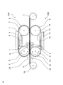
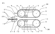
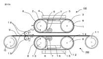
- FIG. 1 shows a schematic diagram of a microstructure transfer apparatus having a heat conduction reducing means in Embodiment 1 of the present invention.
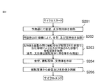
- FIG. 2 is a flowchart of an operation cycle when the transfer is stopped in the first embodiment of the present invention.
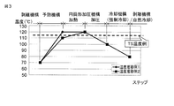
- FIG. 3 is a graph showing a transition example of temperature when the belt-shaped mold and the supporting base material reach each mechanism in Example 1 of the present invention.
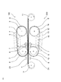
- FIG. 4 shows a schematic view of a microstructure transfer apparatus having a heat conduction reducing means in a state where a peeling mechanism having a peeling angle is used in Example 1 of the present invention.
- FIG. 5 shows a schematic view of a microstructure transfer apparatus according to another embodiment of the present invention.
- FIG. 1 shows a schematic diagram of a microstructure transfer apparatus having a heat conduction reducing means in Embodiment 1 of the present invention.
- FIG. 2 is a flowchart of an operation cycle when the transfer is stopped in the first embodiment of the present invention.
- FIG. 3 is a
- FIG. 6 is a schematic view of a microstructure transfer apparatus in a state where a peeling mechanism having a peeling angle according to another embodiment of FIG. 4 of the present invention is used.
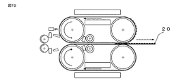
- FIG. 7A shows a schematic diagram of a fine structure transfer device showing a single wafer transfer operation in Embodiment 2 of the present invention.
- FIG. 7B is a schematic view of a fine structure transfer device showing a single wafer transfer operation according to the second embodiment of the present invention.
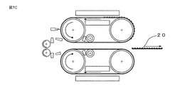
- FIG. 7C is a schematic diagram of a fine structure transfer device showing a single wafer transfer operation according to the second embodiment of the present invention.
- FIG. 8 shows a schematic diagram of a microstructure transfer apparatus having a fracture prevention mechanism in Embodiment 3 of the present invention.
- FIG. 9 is a schematic view of a microstructure transfer device provided with a breakage prevention mechanism in Embodiment 4 of the present invention.
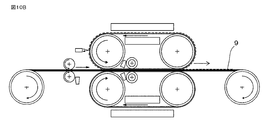
- FIG. 10A is a schematic diagram of a microstructure transfer device including a breakage prevention mechanism in Example 5 of the present invention.
- FIG. 10B shows a schematic diagram of a microstructure transfer device including a breakage prevention mechanism in Example 5 of the present invention.
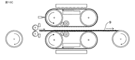
- FIG. 10C is a schematic diagram of a microstructure transfer device including a fracture prevention mechanism in Example 5 of the present invention.
- FIG. 1 shows a schematic diagram of a fine structure transfer apparatus of Example 1 showing an embodiment of the present invention.
- the fine structure transfer apparatus of the present invention includes an upper apparatus 100 and a lower apparatus 200.
- the upper apparatus 100 has a cylindrical pressure having a belt-shaped mold 1 in which a fine structure is formed and an upper cylindrical pressure roller 2 for pressing and heating the belt-shaped mold 1 on the surface of the transfer target 9.
- the mechanism and the belt-shaped mold 1 are mounted on the apparatus main body in a state where the mechanism can be rotated through the upper cylindrical pressure roller 2, the upper peeling roller 3, and the cooling roller 7.
- the lower device 200 includes a support base 12 that conveys the transfer target 9, and the lower cylindrical pressure is applied to a position facing the upper cylindrical pressure roller 2 of the upper device 100 with the transfer target 9 interposed therebetween.
- a roller 13 is disposed, and is attached to the apparatus main body through a lower peeling roller 14 and a cooling roller 7 so as to be rotatable and movable, similarly to the upper apparatus 100.
- An elastic body 8 serving as a close contact mechanism is provided on each surface of the upper cylindrical pressure roller 2 and the lower cylindrical pressure roller 13, and the upper peeling roller 3 and the lower peeling roller 14. The elastic body 8 can be brought into close contact between the belt-shaped mold 1 and the transferred body 9 and between the transferred body 9 and the support base 12 without generating a gap.
- the upper preheating mechanism (belt-shaped mold surface preheating) is just before contact with the upper cylindrical pressure roller 2.
- Preheating to a predetermined temperature can be performed by the mechanism 4 and the belt-shaped mold back surface preheating mechanism 5).
- the support base 12 also moves to the lower cylindrical pressure roller 13 side from the lower peeling roller 14 until the lower preheating mechanism (support base surface preheating mechanism) immediately before contacting the lower cylindrical pressure roller 13. 15. It can be preheated by the support substrate back surface preheating mechanism 16).
- die and a support base material can be set separately in the case of preheating.
- the belt-shaped mold 1 and the support base 12 are uniformly heated to a predetermined temperature by upper and lower cylindrical pressure rollers.
- the transfer body 9 is discharged, and the cooling mechanism (cooling blow nozzle 6) is discharged. And introduced into the cooling roller 7).
- the transfer body 9 sandwiched between the belt-shaped mold 1 and the support base 12 is cooled so that the transfer body 9 becomes a glass transition temperature or lower while maintaining the pressure maintained by the cooling roller 7. .
- the transfer target 9 is supplied from the substrate unwinding roller 10 to the fine structure transfer device and is wound up by the substrate winding roller 11.
- the fine structure transfer apparatus in the present embodiment is such that the transfer target 9 sandwiched between the belt-shaped mold 1 and the support base 12 moves to the cylindrical pressure roller in a non-contact state, and forms a belt-like shape.
- the transfer body 9 is pressed between the mold 1 and the support base 12 by the upper and lower cylindrical pressure rollers.
- the fine structure transfer apparatus according to the present embodiment is configured such that the transfer target 9, the belt-shaped mold 1, and the transfer target 9 are sandwiched between the base unwinding roller 10 and the belt-shaped mold 1 and the support base 12.
- a cooling fluid discharge mechanism 21 for preventing breakage that sprays fluid to lower the surface temperature of the support base 12 is provided, and before or after the transfer is started or the transfer is stopped and the transfer body 9 is connected to the belt-shaped mold 1.
- the fluid for preventing breakage of the transferred body 9 can instantaneously lower the temperature of the transferred body 9, the belt-shaped mold 1, the cylindrical pressure mechanism or the support base 12. In addition, it does not take more heat than necessary, and does not hinder the heating necessary when resuming transfer.
- the cooling fluid discharge mechanism 21 for preventing breakage is a mechanism that sprays a cooling medium using, for example, an electromagnetic valve
- a normally open type electromagnetic valve It is desirable for the mechanism to be able to open the solenoid valve and spray the cooling medium even if the temperature drops.
- a mechanism for storing the cooling medium such as a chamber may be provided so that the cooling medium is sprayed over a certain amount, and a mechanism for spraying the stored cooling medium may be used.
- the cooling fluid discharge mechanism 21 for preventing breakage is preferably a mechanism that can be driven by a battery or operated manually even when power supply is interrupted in consideration of safety when the power is turned off.
- heating of the belt-shaped mold 1 is started from the upper peeling roller 3 to the upper cylindrical pressure roller 2 and the upper preheating mechanism (the belt-shaped mold surface preheating mechanism 4, the belt-shaped mold back surface preheating). This is when the mechanism 5) is entered (S201).
- the rate of temperature increase at this time is proportional to the amount of energy and the temperature increase time, that is, the output to the preheating heater and the feed rate of the belt-shaped mold 1.
- the temperature at this time is preferably around glass transition temperature (TS temperature) as shown in FIG. 3 for the purpose of helping to reach a predetermined temperature.
- the belt-shaped mold 1 comes into contact with the upper cylindrical pressure roller 2 and is heated via the elastic body 8.
- the temperature increase rate at this time also depends on the temperature of the upper cylindrical pressure roller 2 and the contact time.
- a pressure is applied to transfer the fine structure of the mold 1 to the transfer target.
- the transferred object is heated in a state where pressure is applied by the pressure member, so that the transferred object is softened and the fine structure of the mold is transferred to the transferred object 9 (S203).
- the transfer body 9 it is not preferable to heat the transfer body 9 before pressurization in a state where the transfer body 9 is in contact with the belt-shaped mold 1 and the support base 12 because wrinkle-like marks are easily generated during transfer. .
- the belt-shaped mold 1, the transfer body 9 and the supporting base material are cooled to a predetermined temperature (S204). Thereafter, the belt-shaped mold 1 and the support base 12 are peeled from the transfer body 9 (S205).
- the upper and lower peeling rollers 3 and 14 exit from the cooling mechanism (cooling blow nozzle 6 and cooling roller 7) the belt-shaped mold 1 is naturally deprived of heat by the outside air temperature.
- 14 is preferably provided with a heat retaining mechanism.
- the support base 12 is also heated by the lower cylindrical pressure roller 13 in the same manner as the belt-shaped mold 1.
- the upper cylindrical pressure roller 2 is provided with an elastic body 8 in order to apply pressure for a predetermined time in addition to heating, but the elastic body 8 itself has a heat-resistant temperature derived from its material, Since there is an upper limit to the temperature during heating, the temperature cannot be increased so much and the contact time with the upper cylindrical pressure roller 2 can be increased by increasing the diameter of the upper cylindrical pressure roller 2 or decreasing the speed. Absent. Therefore, in order to achieve high throughput and downsizing at the same time, the preheating mechanism (the belt-shaped mold surface preheating mechanism 4 and the belt-shaped mold back surface preheating mechanism 5) is supplied with energy from the outside and preheated to a predetermined temperature. It is best to do.
- a clean inert gas is optimal, but a gas such as compressed air and N 2 gas, water, alcohol, a release agent, a liquid, etc. Various fluids can be applied.
- a roller-shaped one is preferable in order to prevent damage to the belt-shaped mold 1 in the contact type. Few. Therefore, those that can be heated in a non-contact manner are good, and those that use radiant heat are particularly desirable.
- a method of heating by electromagnetic induction is also possible.
- when performing heating, preheating, or heat insulation it may be configured to surround in a room shape in consideration of heating efficiency so that heat does not leak to the outside. Further, in order to prevent the temperature of the belt-shaped mold 1 and the support base 12 from falling after the cooling mechanism, a heater may be incorporated so that the upper and lower peeling rollers can be kept warm.
- the fine structure refers to a structure having a concavo-convex structure in the range of several ⁇ m to several nm.
- the belt-shaped mold is a flat belt-shaped mold having a fine structure formed on the surface and capable of being rotated around a plurality of rollers as described above. It is preferable that the belt-shaped mold has a predetermined strength and has a flexibility capable of smoothly moving in contact with the side surface of the rolled roller.
- limiting in particular in a material, Ni foil, a polyimide film, etc. are illustrated preferably from the point of intensity
- an endless stainless steel belt or a resin belt may be attached with a mold member having a fine structure formed via an adhesive.
- the upper cylindrical pressure roller 2 and the cooling roller 7 of this embodiment rotate with the rotation of the belt-shaped mold 1, and have a drive mechanism that rotates the belt-shaped mold 1.
- the cooling roller 7 and the upper peeling roller 8 preferably have a tension adjusting mechanism for adjusting the tension of the belt-shaped mold 1. The same applies to the rollers 13, 7, and 14 that support the support base 12.
- the upper cylindrical pressure roller 2 and the lower cylindrical pressure roller 13 are constituted by a pair of opposed cylindrical rollers.
- Each of the cylindrical rollers 2 and 13 is a columnar cast product or a cylindrical molded product, has a predetermined strength, and can be rotated by a central axis.
- Alloys, ceramics, engineering plastics, etc. like stainless steel are illustrated preferably from points, such as intensity
- the upper and lower cylindrical pressure rollers 2 and 13 sandwich the transfer target 9 between the belt-shaped mold 1 and the support base 12 and heat and pressurize the transfer target 9. Between the support substrate 12 and the support substrate 12.
- the thrust for pressurization is realized by applying thrust such as air pressure or hydraulic pressure to both ends of the rotary shafts of the upper and lower cylindrical pressure rollers 2 and 13.
- thrust such as air pressure or hydraulic pressure
- the pressure applied by the upper and lower cylindrical pressure rollers 2 and 13 to the transfer target 9, the belt-shaped mold 1 and the support base 12 is adjusted.
- the upper and lower cylindrical pressure rollers 2 and 13 have a built-in heating mechanism such as a heating wire, an inductive heater, and an infrared heater for heating the belt-shaped mold 1, the support base 12 and the transfer target 9. Yes.
- the upper and lower cylindrical pressure rollers 2 and 13 have a drive mechanism for rotating the belt-shaped mold 1 and the support base 12 and transferring the transfer target 9.
- the elastic body 8 is formed on the surfaces of the upper and lower cylindrical pressure rollers of this embodiment in order to apply pressure uniformly.
- the elastic body formed on the roll surface include fluorine rubber, silicone rubber, fluorinated silicone rubber, acrylic rubber, hydrogenated nitrile rubber, ethylene propylene rubber, chlorosulfonated polystyrene, epichlorohydrin rubber, butyl rubber, and urethane rubber.
- Polyimide polycarbonate (PC) / acrylonitrile butadiene styrene (ABS) alloy, polysiloxane dimethylene terephthalate (PCT) / polyethylene terephthalate (PET) copolymer polybutylene terephthalate (PBT) / polycarbonate (PC) alloy, poly Examples include tetrafluoroethylene (PTFE), fluorinated ethylene propylene (FEP), polyarylate, polyamide (PA) / acrylonitrile butadiene styrene (ABS) alloy, modified epoxy, and modified polyolefin.
- PTFE tetrafluoroethylene
- FEP fluorinated ethylene propylene
- PA polyamide
- ABS acrylonitrile butadiene styrene
- epoxy resin unsaturated polyester resin, epoxy isocyanate resin, maleimide resin, maleimide epoxy resin, cyanate ester resin, cyanate ester epoxy resin, cyanate ester maleimide resin, phenol resin, diallyl phthalate resin, urethane resin, Various thermosetting resins such as cyanamide resin and maleimide cyanamide resin, and materials obtained by combining two or more of these may be used.
- the physical properties of the elastic body 8 are preferably those having heat resistance of about 200 ° C. to 300 ° C. and an elastic modulus of about 100 MPa to 4000 MPa. Furthermore, instead of forming the elastic body 8 on the outer peripheral portion of the upper and lower cylindrical pressure rollers, a high-pressure fluid layer may be formed. A coating film for enclosing a high-pressure fluid may be formed on the outermost surfaces of the upper and lower cylindrical pressure rollers, and a high-pressure fluid layer may be formed inside the coating film.
- the coating film of this embodiment is not particularly limited as long as it has heat resistance, pressure resistance and flexibility.
- a composite material such as an engineering plastic such as a polyimide film, a rubber sheet reinforced with a wire, fiber, or the like can be used.
- the high-pressure fluid layer of the present embodiment the entire contact portion between the upper and lower cylindrical pressure rollers and the belt-shaped mold 1 or the support base 12 by the pressure applied to the upper and lower cylindrical pressure rollers.
- a material such as air or nitrogen, a liquid such as silicone oil, or a gel-like substance such as polydimethylsiloxane is preferable.
- the pressure of the high pressure fluid layer is preferably adjustable.
- the transfer target to which the fine structure of this embodiment is transferred is not particularly limited, but is selected according to the desired purpose. Specifically, polyethylene, polypropylene, polyvinyl alcohol, polyvinylidene chloride, polyethylene terephthalate, polyvinyl chloride, polystyrene, ABS resin, AS resin, acrylic resin, polyamide, polyacetal, polybutylene terephthalate, glass reinforced polyethylene terephthalate, polycarbonate, modified Thermoplastic resins such as polyphenylene ether, polyphenylene sulfide, polyether ether ketone, liquid crystalline polymer, fluororesin, polyarate, polysulfone, polyethersulfone, polyamideimide, polyetherimide, thermoplastic polyimide, phenol resin, melamine resin, urea Resin, epoxy resin, unsaturated polyester resin, alkyd resin, silicone resin, diallyl phthalate resin, poly Bromide bismaleimide thermosetting resin poly bis amide triazole, etc
- the support substrate is a substrate that supports a member on which a pattern is formed, and the material thereof is not particularly limited, but has a predetermined strength, and the surface of the member on which the fine structure is formed is flat. I need it. More preferably, in order to continuously form a pattern, a flexible film that can be continuously supplied and wound in a roll shape is preferable. Specifically, various metal materials such as stainless steel and plastics such as polyimide film are preferably exemplified.
- the support base material 12 of the present embodiment is preferably a material having an elastic modulus, a linear expansion coefficient, etc. similar to that of the belt-shaped mold 1 in order to realize the effects of the present invention.
- the shape is preferably a belt shape in continuous transfer. Furthermore, it is a flat belt-like one that can be rolled over a plurality of rolls, has a predetermined strength, and has the flexibility to smoothly move in close contact with the side of the rolled roll Is preferred.
- the material is not particularly limited, but a metal such as Ni or a stainless steel plate or a polyimide film is preferably exemplified from the viewpoint of strength and flexibility.
- the upper and lower peeling rollers 3 and 14 in this embodiment are the state in which the transfer target 9 is in close contact with the belt-shaped mold 1 and the support base 12, and the belt-shaped mold 1 and the support substrate 12 from the transfer target 9. Is for peeling.
- it is a columnar cast product or a cylindrical molded product that has a predetermined strength and can be rotated by a central axis.
- limiting in particular in a material Alloys, ceramics, engineering plastics, etc. like stainless steel are illustrated preferably from points, such as intensity
- an elastic body may be formed on the surface.
- the upper and lower cylindrical pressure rollers 2 and 13 themselves may have a mechanism for rotating. Furthermore, as shown in FIG. 4, an example in which the upper peeling roller 3 and the lower peeling roller 14 are combined and the peeling angle can be adjusted by adjusting the gap between the peeling rollers 3 and 14 is also preferably exemplified.
- the substrate unwinding roll 10 and the take-up roll 11 of this embodiment are for supplying and recovering a belt-shaped transferred body before and after the transfer by rotating, and further applying a predetermined tension to the transferred body 9. It has a brake and drive mechanism for applying.
- the cooling mechanism of the present embodiment is a mechanism for cooling the belt-shaped mold 1, the transfer target 9, and the support base 12 that are pressed and adhered by the upper and lower cylindrical pressure rollers 2 and 13.
- the cooling mechanism include one that cools the transfer body 9 to a glass transition temperature or lower by blowing a gas that serves as a coolant to the integrated belt-shaped mold 1, the transfer body 9, and the support base 12.
- a cooling roller with a built-in cooling mechanism is used to keep the belt-shaped mold 1, the transferred body 9, and the support base 12 in close contact while the transferred body 9 is cooled to the glass transition temperature or lower. It is desirable to arrange 7 immediately after the upper and lower cylindrical pressure rollers 2 and 13. Further, transfer is possible without the cooling roller 7 as shown in FIGS.
- FIG. 7A, 7B, and 7C show Embodiment 2 of the present invention.
- the same reference numerals are given to the same parts as those in the previous embodiment, and the detailed description thereof is omitted.
- symbol can be described only in FIG. 7A for the legibility of a figure.
- FIG. 7A, 7B, and 7C are structures in which the fine structure mold portions of the belt-shaped mold 1 are arranged at predetermined intervals, and the transfer target is not a continuous web-shaped one sheet. The case where it transfers to the short-form to-be-transferred material 20 inserted is shown.
- FIG. 7A shows a state before the short transfer target 20 is loaded into the transfer device one by one by the feed roll 18, and in this state, the upper device 100 and the lower device 200 are positioned at a distance from each other in the vertical direction. The upper device 100 and the lower device 200 are rotated in advance, and the belt-shaped mold 1 is heated to a predetermined temperature.
- FIG. 7B shows a state in which a predetermined number of sheets have been transferred from the short transfer target 20 by the transfer device.
- FIG. 7C shows a state in which the transfer of a predetermined number of sheets is completed and the last short-form transfer target 20 is discharged from the transfer device, and the upper device 100 is raised in preparation for the next transfer preparation and then stopped.
- the sensor 17 for detecting the fine structure mold portion of the belt-shaped mold 1 detects the arrival of the fine structure mold portion, and the substrate feeding mechanism 18, 18 and sensors 19 and 19 that detect the leading end of the transferred body 20 are synchronized with the rotational speed of the belt-shaped mold 1 by matching the leading end of the transferred body 20 with the leading end of the microstructured mold part. It is preferable. It is also possible to manually insert the short-form transfer object 20. For a material having a thickness to be transferred, the insertion of the material 20 to be transferred while the cylindrical pressure mechanism is in a pressurized state leads to damage to the elastic body applied to the cylindrical pressure mechanism. A technique using the tip detection sensor 17 of the fine structure mold part and the tip detection sensor 19 of the transfer target 20 is desirable.
- the belt-shaped mold 1 is provided with one microstructured mold part. This is based on the size of the belt-shaped mold 1 and the size of the microstructured mold part. It is also possible to provide a plurality of related items. In any case, care should be taken so that the transfer object that has already been transferred in the transfer process is not sandwiched again between the upper device 100 and the lower device 200.
- FIG. 8 shows another embodiment 3 of the mechanism for preventing breakage of the member to be transferred according to the present invention.
- the same parts as those in the above embodiment are given the same reference numerals and their detailed explanations are omitted. .
- Example 3 shown in FIG. 8 instead of the cooling fluid discharge mechanism 21 for preventing breakage shown in FIG. 1, before the transfer target 9 is sandwiched between the belt-shaped mold 1 and the support base 12, the transfer target is transferred.
- a breakage prevention material insertion mechanism 22 for inserting a sheet-like material that reduces direct heat conduction to the body 9 is provided.
- the sheet-like material to be inserted any material having heat resistance equal to or higher than the glass transition temperature of the transfer target 9 may be used, but a material having excellent heat resistance and flexibility such as a fluororesin and a silicon resin is optimal. .
- a fiber material, a metal material, a gel, etc. may be sufficient if it is a sheet form.
- FIG. 9 shows another embodiment 4 of the mechanism for preventing breakage of the transferred body of the present invention.
- the same reference numerals are given to the same parts as those in the above embodiment, and the detailed description thereof is omitted. .
- a roller for lowering the surface temperature of the belt-shaped mold 1 and the support base 12 before clamping the transfer target 9 is used instead of the cooling fluid discharge mechanism 21 for preventing breakage of FIG. You may have the cooling roller 25 for the fracture
- each of the cooling mechanisms for preventing breakage shown in the first, third and fourth embodiments has a plurality of types.
- FIGS. 10A, 10B, and 10C show Example 5 of the present invention.
- the same reference numerals are given to the same portions as those in the above-described embodiment, and the detailed description thereof is omitted.
- 10A, 10B, and 10C are explanatory views showing a fine structure transfer apparatus using a web-shaped transfer target 9.
- FIG. 10A, 10B, and 10C are explanatory views showing a fine structure transfer apparatus using a web-shaped transfer target 9.
- the transfer target 9 is pulled out from the substrate unwinding roller 10 and passed between the upper device 100 and the lower device 200 in advance to the substrate take-up roller 11. Winding is performed for a predetermined length.
- the upper device 100 and the lower device 200 are positioned at a distance from each other in the vertical direction, and the belt-shaped mold surface preheating mechanism 4, the belt-shaped mold back surface preheating mechanism 5 of the upper device 100, and the support base of the lower device 200.
- the material surface preheating mechanism 15 and the supporting substrate back surface preheating mechanism 16 are preheated. Further, as shown in FIG.
- the upper device 100 while preheating the transferred body 9, while rotating the transferred body 9 as it is, the upper device 100 is lowered to sandwich the transferred body 9, and the upper cylindrical pressure roller 2 is inserted. The lower cylindrical pressure roller 13 is pressed. As a result, the heated belt-shaped mold 1 and the support base 12 are in close contact with the transfer body 9 and are thermoformed. After continuing the heat forming as it is, as shown in FIG. 10C, when the end of the transferred object 9 is detected by the base material detection sensor 19, the upper device 100 is quickly raised and transferred by the belt-shaped mold 1. The thermoforming to the body 9 is finished. In this case, the upper device 100 and the lower device 200 continue to rotate for a while. By adopting such a procedure, a specific portion of the transfer target 9 is not continuously pressed by the upper and lower cylindrical pressure rollers at the start and stop of the transfer. It is possible to prevent the transferred material 9 from being blown by continuing to heat a specific portion.
Landscapes
- Physics & Mathematics (AREA)
- Health & Medical Sciences (AREA)
- Oral & Maxillofacial Surgery (AREA)
- Thermal Sciences (AREA)
- Engineering & Computer Science (AREA)
- Mechanical Engineering (AREA)
- Electromagnetism (AREA)
- Toxicology (AREA)
- Shaping Of Tube Ends By Bending Or Straightening (AREA)
- Exposure Of Semiconductors, Excluding Electron Or Ion Beam Exposure (AREA)
Abstract
熱式の連続転写装置において、転写の開始、乃至は終了時における、被転写体の破断を防止する機構を提供する。 本発明は、転写開始及び停止時において、被転写体(9)がベルト状金型(1)と支持基材(12)からの熱伝導を妨げ、破断(溶断)防止するために、加圧・加熱を行う上部及び下部円筒形加圧ローラがベルト状金型(1)と被転写体(9)とを挟持する直前に、上部及び下部円筒形加圧ローラ表面、ベルト状金型(1)の表面、支持基材(12)の表面、及び被転写体(9)を瞬間的に冷却する機構を備える、若しくは上部及び下部円筒形加圧ローラから被転写体(9)への熱伝導を防止する素材を挿入する機構を有し、当該熱伝導を防止する素材と共に挟持することで、被転写体(9)が過剰な加熱により破断することを防ぐ。
Description
本発明は、表面にナノメートル又はマイクロメートル単位の微細な凹凸が形成されたスタンパを用い、被転写体に押付け微細構造体を整形する微細構造転写装置及び微細構造転写方法に関わり、特にローラの回転により連続的に熱成形を行う連続転写装置及び微細構造転写方法に関する。
近年、熱式のナノインプリント技術においては、表面にナノメートル又はマイクロメートル単位の微細な凹凸が形成されたスタンパと被転写体とを、極平坦に加工されたプレート同士で挟み込むか、静水圧にて均一な圧力分布で圧力を保った状態とし、被転写体のガラス転移温度よりも高温に加熱し被転写体を軟化させた後に加圧を行いスタンパの形状に押し込み、その状態を保ったまま被転写体のガラス転移温度よりも低温になるまで冷却を行い、被転写体を硬化させ成型するのが、熱式のナノインプリント装置の一般的な転写方法である。
ここで、熱式のナノインプリント装置においては、前述の均一な圧力にて挟み込み転写を行うので、平行平板型やバッチ方式とも称される転写装置となっている。また、前述の転写工程を各工程毎に行う形で、装置を連続的に設置することにより、枚葉毎の転写を行う、連続バッチ方式の装置開発もされており、生産性を向上させている。更に、量産性を上げ、大面積、且つ高速転写を目指す技術として、加熱可能なローラを対に設置、またはローラを2本以上の複数設置した状態で、前述の複数本からなるローラにベルトをかけ、それらを対とし、スタンパと被転写体とを挟み込み、加圧、加熱、冷却、剥離までを一貫で行うことで転写を行う、連続転写方式の装置技術も開発されてきており、枚葉毎の生産からロール材単位での量産化に向けた技術が発展してきている。
また、ナノインプリントの技術としては、転写を行う装置だけではなく、前述の連続転写方式の装置に対応した、極微細な凹凸が形成されたスタンパの技術開発も必須であり、近年は特に大形化、シームレス化、低コスト化などの開発が進んでおり、装置とスタンパの両面から技術開発が推進されている。
微細なパターン形成を低コスト、且つ高スループットで行うための技術が下記特許文献1、及び2において開示されている。特許文献1は、金属製の無端ベルトにスタンパを張り合わせることでベルト状の金型とし、複数本のローラにてベルトを支え、回転駆動させ、加熱、加圧、冷却、剥離までを連続的に行うことでロール材などの被転写体にパターン形成できる技術である。これらの技術は、被転写体上に形成したいパターンと同じパターンの凹凸を有するモールドを、被転写基板表面に形成されたレジスト膜層、又は被転写体そのものに対して型押しすることで所定のパターンを転写するものである。
例えば、特許文献1(特開2008-155413号公報)には、無端ベルト状のスタンパを基板表面に形成されたレジスト層に対してヒータ内臓のローラで型押しすることで、スタンパにおけるパターンを連続的に転写するものが開示されている。これは、アスペクト比1以上の高アスペクト比微細構造体を高スループットで形成することを課題とし、1対の円筒形加圧加熱ロールから構成された微細な構造を転写するための微細構造転写装置を用い、金型と基材表面の接触部の圧力が1MPa以上であり、且つ、基材の進行方向と平行な加圧部分の幅Wが数式1を満たす条件でパターン転写を行う。
W≧128・η・a/P・・・・数式1
上記数式1において、η:基材表面の粘度、a:ロールの周速度、P:加圧部圧力である。
W≧128・η・a/P・・・・数式1
上記数式1において、η:基材表面の粘度、a:ロールの周速度、P:加圧部圧力である。
特許文献2(特開2006-326948号公報)には、さらに高速転写を可能とするため、加熱ローラ、及び加熱層を多段に持たせた技術が開示されている。これは、ロールの回転速度を高くし生産性を高めても期待したパターンを転写することができる微細構造転写装置を提供することである。樹脂層に微細なパターンを有するスタンパを加熱加圧することにより、樹脂層に該スタンパの微細パターンを転写する微細構造転写装置であり、スタンパを有するべルトをスタンパのパターン面が樹脂層側となるようにして樹脂層と対向させ、多段に設けたローラにより9を介してスタンパを樹脂層に加熱加圧し、転写する。
特許文献3(特開2011-98530号公報)は、高スループット、且つ小形化ができ、加熱、加圧前後において、皺状痕のような転写不良の発生を抑制可能な微細構造転写装置の加熱冷却機構を提供する。ベルト金型が加熱、加圧ローラに接触する直前に、ベルト金型表面のみを加熱するための、予熱ヒータを備え、ベルト金型表面の温度を、加熱、加圧ローラと同等とすることにより、確実に所定温度とすることができ、さらに、加熱、加圧ローラ直後に、冷却ローラ、又は冷却ノズルを取付けることにより、強制冷却、及び圧力保持を行い冷却が行え、パターン転写を行う微細構造転写装置である。
特許文献4(特開平10-291251号公報)は、転写部と剥離部とに大きな温度差を設けてシートを安定して生産できる熱可塑性樹脂のシート加工装置、シート加工方法、およびそのシートの提供。スタンパーロールにおける第1冷却ロールとの間の空隙部に対応した位置を加熱手段で加熱し、各ロールが互いに接触し合う冷却部を第1冷却ロールで冷却する。これによれば、空隙部が断熱層として作用するため、転写部の上流側では、スタンパーロールが冷却ロールに影響されずに効率よく加熱され、下流側では加熱手段に影響されずに効率よく冷却され、転写部、剥離部間に大きな温度差を生じさせることができる。
これらの転写装置及び技術において、ロール材をセットし、リールtoリールで転写を行った際、加熱、加圧、冷却、剥離まで連続的に行うため、加熱部のローラは常に高温の状態を保つ必要がある。しかしながら、装置を永久に動かし続けることは不可能であり、装置の停止状態から駆動し、装置駆動状態から停止することは必須である。このような装置の運転状態で、転写開始時においては、前述の加熱部のローラが被転写体と接触し、熱、及び圧力が加えられる。また、転写の終了時においては被転写体を挟持した状態を解除し、被転写体とベルト状の金型とが剥離される。このような装置において、装置を停止状態から運転を開始したり、運転状態から停止状態に移る際に、加熱部のローラが高温状態であると、前述の接触時には被転写体へ局所的な応力と熱が加えられ、被転写体破断する恐れがある。また、前述の解除時においても被転写体がガラス転移温度に達している状態から剥離されるため、被転写体が延伸し破断してしまう。
そこで、運用方法として、前述の加熱部のローラを被転写体のガラス転移温度以下としてから、被転写体と接触、及び剥離を行えばこれらの破断を防ぐことは可能である。また、ロール材を使用しきるまで運用すれば、前述解除時の破断は起こらない。ここで、本連続転写を行う装置においては、加熱を行うローラ、乃至は加熱、及び加圧を共に行うローラは、高温、且つ高荷重に耐えうるために金属体であり、熱容量が非常に高いため、前述のこれらの加熱ローラ自体を加熱、冷却するのには時間が掛かってしまう。途中で転写をやめる場合は、前述の加熱ローラの温度を下げてから転写を停止させる必要があるため、加熱ローラの温度を下げている間、被転写体が巻き取られており、歩留まりが悪化すると言った問題があった。
また、転写を急停止させた場合は被転写体が破断するため、ロール材を装置へ再セットする必要があり、タクトが悪化すると言う問題があった。そこで本発明の目的は、転写の開始時、及び終了時の加熱部ローラの温度を下げる手間を省き、直ぐにベルト状の金型と被転写体とを剥離できる状態にすると共に、転写を急停止させる場合においても、被転写体の破断を防ぐ技術を提供することにある。
上記課題を解決するために、本発明の微細構造転写装置は、ベルト状金型を用いて被転写体の表面に微細構造を成形する微細構造転写装置において、当該微細構造転写装置は、前記ベルト状金型を加熱し、加圧するための上部加圧ローラと、前記被転写体を支持するベルト状の支持基材を加熱し、加圧するための下部加圧ローラと、からなる加圧機構と、前記被転写体から前記ベルト状金型を剥離する上部剥離ローラと、前記被転写体から前記支持基材を剥離する下部剥離ローラとからなる剥離機構を有しており、前記ベルト状金型は、前記上部加圧ローラと前記上部剥離ローラによって回転可能に装着され、かつ前記支持基材は、前記下部加圧ローラと前記下部剥離ローラによって回転可能に装着されており、さらに、前記微細構造転写装置は、前記ベルト状金型及び前記支持基材から前記被転写体への熱伝導を低減する熱伝導低減手段を有し、転写開始時においては、前記被転写体を前記ベルト状金型及び前記支持基材に対して非接触状態で前記加圧機構まで移動させ、前記熱伝導低減手段を作用させて前記被転写体への熱伝導を低減した状態で、前記被転写体を前記ベルト状金型及び前記支持基材にせ接触させて、前記加圧機構によって加圧することを特徴とする。
更に本発明の微細構造転写装置は、前記熱伝導低減手段は、前記上・下部加圧ローラ及び前記上・下部剥離ローラに対して冷媒となる流体を吹きかける冷却流体吐出手段であることを特徴とする。
また本発明の微細構造転写装置は、前記熱伝導低減手段は、前記被転写体と前記上・下部加圧ローラ及び前記上・下部剥離ローラ間に熱伝動を妨げるシート材を挿入する破断防止材挿入手段であることを特徴とする。
更に本発明の微細構造転写装置は、前記熱伝導低減手段は、前記上・下部加圧ローラ及び前記上・下部剥離ローラに対して押し付ける冷却機能を具備する冷却ローラであることを特徴とする。
また本発明の微細構造転写装置は、前記ベルト状金型が前記上部剥離ローラから剥離されて前記上部加圧ローラに移動する間に前記ベルト状金型を予熱する予熱部を備えたことを特徴とする。
本発明の微細構造転写装置は、ベルト状金型を用いて被転写体の表面に微細構造を成形する微細構造転写装置において、当該微細構造転写装置は、微細構造転写前の前記被転写体を供給する巻出しローラと、微細構造転写後の前記被転写体を巻き取る巻取りローラと、上下に昇降可能であり、前記ベルト状金型を加熱し、加圧するための上部加圧ローラと、同じく上下に昇降可能であり、前記被転写体を支持するベルト状の支持基材を加熱し、加圧するための下部加圧ローラと、からなる加圧機構と、前記被転写体が前記加圧機構によって前記ベルト状金型及び前記支持基材とで挟持されて密着した状態から、前記ベルト状金型及び前記支持基材を前記被転写体から剥離する上部剥離ローラ及び下部剥離ローラとからなる剥離機構を有しており、前記ベルト状金型は、前記上部加圧ローラと前記上部剥離ローラによって回転可能に装着され、かつ前記支持基材は、前記下部加圧ローラと前記下部剥離ローラによって回転可能に装着されており、転写開始時においては、前記巻取りローラを駆動させて前記被転写体を巻取ると共に、予熱済みの前記加圧機構によって巻取り中の前記被転写体を挟み込むことで、前記被転写体を過剰に加熱することなく、前記被転写体を前記ベルト状金型及び前記支持基材にせ接触させて、前記加圧機構によって加圧することを特徴とする。
本発明の微細構造転写方法は、ベルト状金型を用いて被転写体の表面に微細構造を成形する微細構造転写装置による微細構造転写方法において、当該微細構造転写装置は、前記ベルト状金型を加熱し、加圧するための上部加圧ローラと、前記被転写体を支持するベルト状の支持基材を加熱し、加圧するための下部加圧ローラと、からなる加圧機構と、前記被転写体から前記ベルト状金型を剥離する上部剥離ローラと、前記被転写体から前記支持基材を剥離する下部剥離ローラとからなる剥離機構を有しており、前記ベルト状金型は、前記上部加圧ローラと前記上部剥離ローラによって回転可能に装着され、かつ前記支持基材は、前記下部加圧ローラと前記下部剥離ローラによって回転可能に装着されており、さらに、前記微細構造転写装置は、前記ベルト状金型及び前記支持基材から前記被転写体への熱伝導を低減する熱伝導低減手段を有しており、転写開始時においては、前記被転写体を前記ベルト状金型及び前記支持基材に対して非接触状態で前記加圧機構にまで移動させた後、前記熱伝導低減手段を作用させて前記被転写体への熱伝導を低減した状態で、前記被転写体を前記ベルト状金型及び前記支持基材にせ接触させて、前記加圧機構によって加熱し加圧することを特徴とする。
本発明によれば、転写の開始時及び停止時における被転写体の損傷を防ぐことができ、被転写体の歩留まりを向上させ、転写を素早く開始、又は停止を可能とすることでタクトアップも可能な微細構造転写装置及び微細構造転写方法を提供できる。
本発明の微細構造転写装置および転写方法について説明する。なお、本明細書においては、本発明を構成する部品等を「上部装置」「下部装置」或いは「上部加圧ローラ」「下部加圧ローラ」等として、「上」「下」という修飾語を用いて表記している。しかしながら、これは、単に図示した装置における上下関係から部品名称を付しているものであり、発明思想として上下が問題となるものではなく、上下は逆転しても本発明の発明思想に属するものである。以降、実施例の説明においては、「上部加圧ローラ」は「上部円筒形加圧ローラ」とし、「下部加圧ローラ」は「下部円筒形加圧ローラ」として説明する。さらに、実施例の説明において、「破断防止用の冷却流体吐出機構」についての記述があるが、これは「破断」や「損傷」を抑止し減少させる意味であり、完全に防止することまでを意図したものではない。また、実施例おいて用いる「機構」とは、所定の機能を持った構成物を意味し、「手段」と同じ意味で用いている。
図1に本発明の実施形態を示す実施例1の微細構造転写装置概略図を示す。本発明の微細構造転写装置は、上部装置100と下部装置200から構成される。上部装置100は、微細構造が形成されたベルト状金型1、被転写体9の表面にベルト状金型1を加圧、加熱するための上部円筒形加圧ローラ2を有する円筒形加圧機構とこのベルト状金型1は上部円筒形加圧ローラ2、上部剥離ローラ3、冷却ローラ7の3本を介して装置本体に回転移動可能な状態で装着される。
また、下部装置200は、被転写体9を搬送する支持基材12を具備し、上部装置100の上部円筒形加圧ローラ2と被転写体9を挟んで対向する位置に下部円筒形加圧ローラ13が配置され、更に上部装置100と同様に下部剥離ローラ14、冷却ローラ7の3本を介して装置本体に回転移動可能な状態で装着される。尚、上部円筒形加圧ローラ2及び下部円筒形加圧ローラ13、及び上部剥離ローラ3及び下部剥離ローラ14の各々の表面には、密着機構たる弾性体8が設けられる。この弾性体8によってベルト状金型1と被転写体9の間、被転写体9と支持基材12の間に間隙が生じることなく密着させることができる。
ここで、ベルト状金型1は、上部剥離ローラ3及び上部円筒形加圧ローラ2の回転によって移動する際、上部円筒形加圧ローラ2へ接する直前まで上部予熱機構(ベルト状金型表面予熱機構4、ベルト状金型裏面予熱機構5)により所定温度まで予熱できる。また、支持基材12に関しても、下部剥離ローラ14から下部円筒形加圧ローラ13側へ移動している際、下部円筒形加圧ローラ13に接する直前まで下部予熱機構(支持基材表面予熱機構15、支持基材裏面予熱機構16)にて予熱できる。また予熱の際、ベルト状金型と支持基材の所定温度は個別に設定できる。その後、ベルト状金型1、及び支持基材12は上下の円筒形加圧ローラにて所定温度まで均一に加熱される。次に、上下2つの円筒形加圧ローラによって、転写体9がベルト状金型1と支持基材12の間で加圧密着された後に転写体9が排出され、冷却機構(冷却ブローノズル6、冷却ローラ7)に導入される。この時、ベルト状金型1と支持基材12に挟まれた転写体9は、冷却ローラ7によって圧力を保った状態を維持したまま、被転写体9をガラス転移温度以下となるよう冷却する。以上のような手順により、被転写体9は、基材巻き出しローラ10から微細構造転写装置へ供給され、基材巻き取りローラ11にて巻き取られる。
本実施例における微細構造転写装置は、上記のように、ベルト状金型1と支持基材12に挟まれた被転写体9が、非接触状態で円筒形加圧ローラまで移動し、ベルト状金型1と支持基材12との間に被転写体9が配置された状態で上下の円筒形加圧ローラにより加圧される。更に本実施例における微細構造転写装置は、被転写体9が基材巻き出しローラ10からベルト状金型1及び支持基材12に挟持される間に被転写体9、ベルト状金型1及び支持基材12の表面温度を下げるために流体を吹きかける破断防止用の冷却流体吐出機構21を備えており、転写を開始する前後、又は、転写を止めて転写体9をベルト状金型1と支持基材12にて挟持した状態を解除する前後に流体を吹きかけることで、上下の円筒形加圧ローラによって過剰に被転写体9が加熱されることを抑止し防止する。これによって被転写体9が溶着して破断するのを防止することができる。ここで、前記の被転写体9の破断を防止する流体は瞬間的に被転写体9、ベルト状金型1、前記円筒形加圧機構乃至は支持基材12の温度を低下させることができ、さらには必要以上に熱を奪うことがなく、転写を再開する際に必要な加熱の妨げになることもない。
破断防止用の冷却流体吐出機構21は、例えば電磁弁を使用して冷却媒体を吹きかける機構であれば、ノーマルオープンタイプの電磁弁を使用することが好ましく、非常時に停止を掛けた際には電源が落ちても電磁弁が開放され、冷却媒体が吹きかけることが可能な機構であることが望ましい。また、冷却媒体が一定量以上吹きかかるよう、チャンバなど冷却媒体を貯蔵する機構を設け、貯蔵分の冷却媒体が吹きかかる機構でも良い。また破断防止用の冷却流体吐出機構21は、電源が落ちた際の安全を考慮し電力供給が途絶えてしまってもバッテリーによる駆動や手動による動作が可能な機構が望ましい。
次に、ベルト状金型1及び支持基材12の温度制御フローについて図2のフローチャート及び図3を用いて説明する。まず、ベルト状金型1の加熱が開始されるのは、上部剥離ローラ3から上部円筒形加圧ローラ2へ向かい、上部予熱機構(ベルト状金型表面予熱機構4、ベルト状金型裏面予熱機構5)に入った際である(S201)。このときの昇温速度は、エネルギー量と昇温時間、つまりは、予熱ヒータへの出力とベルト状金型1の送り速度により比例関係が得られる。このときの温度としては、所定温度に達する補助となることが目的のため、図3に示す通り、ガラス転移温度(TS温度)前後となるのが望ましい。
次に、S202にてベルト状金型1は上部円筒形加圧ローラ2に接触し、弾性体8を介して加熱される。このときの昇温速度も、上部円筒形加圧ローラ2の温度と接触時間に依存される。次に、ベルト状金型1と支持基材12の間に被転写体9が配置された状態で、金型1の微細構造を被転写体に転写するための圧力を印加した状態となる。加圧部材により圧力が印加された状態で被転写体を加熱することで、被転写体を軟化させ、金型の微細構造が被転写体9に転写される(S203)。ここで、被転写体9がベルト状金型1及び支持基材12と接触した状態で、加圧前に被転写体9を加熱することは転写時に皺状痕を発生しやすくなるため好ましくない。次に、S202、S203でベルト状金型1の微細構造を被転写体9に転写した後、所定の温度までベルト状金型1、被転写体9、及び支持基材を冷却し(S204)、その後、被転写体9からベルト状金型1及び支持基材12を剥離する(S205)。ここで、冷却機構(冷却ブローノズル6、冷却ローラ7)から上下剥離ローラ3,14を出るまでは、ベルト状金型1は外気温に熱を奪われ自然に降温するため、上下剥離ローラ3,14に保温機構を付加するのが好ましい。また、支持基材12についても、ベルト状金型1と同様に下部円筒形加圧ローラ13によって加熱される。
ここで、上部円筒形加圧ローラ2には、加熱する以外に、圧力を所定時間掛けるため、弾性体8が備えられているが、弾性体8自体はその材質に由来する耐熱温度があり、加熱に際し温度に上限があるため、それ程温度が上げられず上部円筒形加圧ローラ2との接触時間を増加させるには、上部円筒形加圧ローラ2の径を大きくするか、速度を落とすほかない。そのため高スループット化、及び小形化を同時に行うためには、上記予熱機構(ベルト状金型表面予熱機構4、ベルト状金型裏面予熱機構5)にて、外部よりエネルギーを与え、所定温度まで予熱を行うのが最良である。
破断防止用の冷却流体吐出機構21で使用する流体としては、クリーンな不活性ガスであれば最適であるが、圧縮空気、N2ガス等の気体、水、アルコール、離型剤など、液体等、様々な流体が適応可能である。
ベルト状金型表面予熱機構4及びベルト状金型裏面予熱機構5としては、接触式ではベルト状金型1を損傷させないためにもローラ形状のものが望ましいが、接触時間が少なく与えられる熱量も少ない。そこで、非接触にて加熱が行えるものが良く、特に輻射熱を利用したものが望ましい。電磁誘導にて加熱する方法も可能である。さらに、熱風にて加熱する方法もある。ここで、加熱、予熱又は保温を行う際は、加熱効率を考慮して部屋状に囲うよう構成し、熱が外部に漏れないようにしても良い。また、冷却機構後におけるベルト状金型1及び支持基材12の降温を防ぐため、上下剥離ローラに保温を行えるようにヒータを内蔵しても良い。
本実施例において、微細構造とは数μmから数nm程度の範囲の凹凸構造を有する構造体を言う。また、本実施例において、ベルト状金型とは、表面に微細構造が形成され、上記のように複数のローラに掛渡して回転させることが可能な平帯状のものである。ベルト状金型は所定の強度を有し、掛渡されたローラ側面をスムーズに密着移動できる可とう性を有しているものが好ましい。材質は特に制限がないが、Ni箔やポリイミドフィルムなどが強度、可とう性の点から好ましく例示される。また、エンドレスのステンレスベルトや樹脂ベルト上に接着剤を介して微細構造が形成された金型部材を張付けたものでも良い。
また、本実施例の上部円筒形加圧ローラ2及び冷却ローラ7はベルト状金型1の回転に伴って回転するが、それ自身がベルト状金型1を回転させる駆動機構を有していてもよく、冷却ローラ7及び上部剥離ローラ8はベルト状金型1の張りを調整する張力調整機構を有していることがより好ましい。支持基材12を支持する各ローラ13,7,14についても同様である。
本実施例の上部円筒形加圧ローラ2及び下部円筒形加圧ローラ13は対向する1対の円筒状のローラにより構成される。この円筒状の各ローラ2,13は、円柱状の鋳造品または円筒形の成形品であり、所定の強度を有し、中心軸により回転可能なものである。材質に特に制限はないが、ステンレスのような合金やセラミックス、エンジニアリングプラスチックなどが強度、成形性などの点より好ましく例示される。この上部及び下部円筒形加圧ローラ2,13は、被転写体9をベルト状金型1と支持基材12とで挟み、加熱し、加圧するとともに、被転写体9をベルト状金型1と支持基材12間で挟んで移送させる。加圧のための推力は上部及び下部円筒形加圧ローラ2,13の回転軸両端にエアー圧又は油圧等の推力を加えることで実現される。この推力を調整することで上部及び下部円筒形加圧ローラ2,13が被転写体9、ベルト状金型1及び支持基材12に加える圧力を調整する。さらに、ベルト状金型1、被転写体9及び支持基材12に対してローラ全体を均一に加圧するために、回転軸両端の圧力を独立で調整する均一加圧調整機構を有することが好ましい。また、上部及び下部円筒形加圧ローラ2,13はベルト状金型1、支持基材12及び被転写体9を加熱するために電熱線、インダクティブヒータ、赤外線ヒータ等による加熱機構を内蔵している。また、上部及び下部円筒形加圧ローラ2,13は、ベルト状金型1、支持基材12の回転および被転写体9移送のための駆動機構を有している。
また、本実施例の上部及び下部円筒形加圧ローラの表面には弾性体8が形成されていることが圧力を均一にかける上で好ましい。ロール表面に形成する弾性体としては、フッ素ゴム、シリコーンゴム、フッ化シリコーンゴム、アクリルゴム、水素化ニトリルゴム、エチレンプロピレンゴム、クロロスルホン化ポリスチレン、エピクロルヒドリンゴム、ブチルゴム、ウレタンゴム等が挙げられる。また、ポリイミド(PI)、ポリカーボネート(PC)/アクリロニトリルブタジエンスチレン(ABS)アロイ、ポリシロキサンジメチレンテレフタレート(PCT)/ポリエチレンテレフタレート(PET)共重合ポリブチレンテレフタレート(PBT)/ポリカーボネート(PC)アロイ、ポリテトラフルオロエチレン(PTFE)、フロリネイテッドエチレンプロピレン(FEP)、ポリアリレート、ポリアミド(PA)/アクリロニトリルブタジエンスチレン(ABS)アロイ、変性エポキシ、変性ポリオレフィン等が挙げられる。この他にもエポキシ樹脂、不飽和ポリエステル樹脂、エポキシイソシアネート樹脂、マレイミド樹脂、マレイミドエポキシ樹脂、シアン酸エステル樹脂、シアン酸エステルエポキシ樹脂、シアン酸エステルマレイミド樹脂、フェノール樹脂、ジアリルフタレート樹脂、ウレタン樹脂、シアナミド樹脂、マレイミドシアナミド樹脂等の各種熱硬化性樹脂及びこれらを2種以上組み合わせた材料でもよい。
この弾性体8の物性としては、200℃から300℃程度までの耐熱性を有し、弾性率が100MPaから4000MPa程度のものが好ましい。さらに、上部及び下部円筒形加圧ローラの外周部に弾性体8を形成する代わりに高圧流体層を形成してもよい。上部及び下部円筒形加圧ローラの最表面に高圧流体を封入するための被覆膜が形成され、この被覆膜内部に高圧流体層が形成されているものを用いてもよい。本実施例の被覆膜としては耐熱性、耐圧性と可撓性を有しているものであれば特に制限はない。具体的にはステンレス等の金属箔のほか、ポリイミドフィルム等のエンジニアリングプラスチックやワイヤーや繊維等により補強されたゴムシートのような複合材料等が挙げられる。また、本実施例の高圧流体層としては、上部及び下部円筒形加圧ローラに加えられる圧力により、上部及び下部円筒形加圧ローラとベルト状金型1又は支持基材12との接触部分全体に均一な静水圧がかかるものが好ましく、具体的には、空気や窒素等の気体の他、シリコーンオイル等の液体の他、ポリジメチルシロキサン等のゲル状物質が挙げられる。この高圧流体層の圧力は調整できることが好ましい。
本実施例の微細な構造が転写される被転写体は、特に限定されないが、所望する目的に応じて選択される。具体的には、ポリエチレン、ポリプロピレン、ポリビニルアルコール、ポリ塩化ビニリデン、ポリエチレンテレフタレート、ポリ塩化ビニール、ポリスチレン、ABS樹脂、AS樹脂、アクリル樹脂、ポリアミド、ポリアセタール、ポリブチレンテレフタレート、ガラス強化ポリエチレンテレフタレート、ポリカーボネート、変性ポリフェニレンエーテル、ポリフェニレンスルフィド、ポリエーテルエーテルケトン、液晶性ポリマー、フッ素樹脂、ポリアレート、ポリスルホン、ポリエーテルスルホン、ポリアミドイミド、ポリエーテルイミド、熱可塑性ポリイミド等の熱可塑性樹脂や、フェノール樹脂、メラミン樹脂、ユリア樹脂、エポキシ樹脂、不飽和ポリエステル樹脂、アルキド樹脂、シリコーン樹脂、ジアリルフタレート樹脂、ポリアミドビスマレイミド、ポリビスアミドトリアゾール等の熱硬化性樹脂、及びこれらを2種以上ブレンドした材料を用いることも可能である。
これら樹脂は単体のフィルム状で供給されるか、支持基板表面上に数nmから数十μm形成されている場合もある。ここで支持基板とはパターンが形成される部材を支持する基板であり、その材質は特に限定されないが、所定の強度を有するもので、微細構造体が形成される部材の表面が平坦なものであれば良い。さらに好ましくはパターンを連続的に形成するために、連続的に供給できるよう屈曲性を有しロール状に巻きつけられるものが好ましい。具体的には、ステンレス等の各種金属材料やポリイミドフィルムのようなプラスチック等が好ましく例示される。
本実施例の支持基材12とは、弾性率、線膨張係数等がベルト状金型1と類似した材料であることが本発明の効果を実現する上で好ましい。形状はベルト状であることが連続転写において好ましい。さらに、複数のロールに掛渡して回転させることが可能な平帯状のものであり、所定の強度を有し、掛渡されたロール側面をスムーズに密着移動できる可撓性を有しているものが好ましい。材質は特に制限がないが、Niやステンレス板等の金属やポリイミドフィルムなどが強度、可撓性の点から好ましく例示される。
本実施例の上部及び下部剥離ローラ3,14とは、被転写体9がベルト状金型1及び支持基材12に密着した状態より、被転写体9からベルト状金型1及び支持基板12を剥離するためのものである。具体的には一対の円筒形加圧ローラを軸にベルト状金型1および支持基材12の進行方向を変える働きをするものであれば特に制限はない。具体的には円柱状の鋳造品または円筒形の成形品であり所定の強度を有し中心軸により回転可能なものである。材質に特に制限はないが、ステンレスのような合金やセラミックス、エンジニアリングプラスチックなどが強度、成形性などの点より好ましく例示される。また、その表面に弾性体が形成されたものでもよい。
さらに、上部及び下部円筒形加圧ローラ2,13自体が自転する機構を有しているものでも良い。さらには図4に示すように、上部剥離ローラ3と下部剥離ローラ14が組み合わされ、各剥離ローラ3,14のギャップを調整することで各々剥離角度の調整が可能なものも好ましく例示される。
本実施例の基材巻き出しロール10及び巻き取りロール11は回転することにより、転写前後の帯状の被転写体を供給、回収するためのものであり、更に被転写体9に所定の張力を与えるためのブレーキおよび駆動機構を有している。
本実施例の冷却機構は、上部及び下部円筒形加圧ローラ2,13により加圧され密着したベルト状金型1と被転写体9、支持基材12を冷却するための機構である。冷却機構として、一体化したベルト状金型1と被転写体9、支持基材12に冷媒となる気体を吹き付けることにより被転写体9をガラス転移温度以下まで冷却するものが例示される。ここで、被転写体9がガラス転移温度以下に冷却される間に、ベルト状金型1、被転写体9、支持基材12が密着状態を保つために、冷却機構が内蔵された冷却ローラ7を上部及び下部円筒形加圧ローラ2,13直後に配置するのが望ましい。また、図5、図6のように冷却ローラ7がなくとも転写可能である。
図7A、図7B及び図7Cは本発明の実施例2を示したものであり、前記実施例と同一部分には同一符号を付し、その詳細な説明を省略する。なお、符号は図の見易さのために、図7Aにのみ記載していうる。
図7A、図7B及び図7Cは、ベルト状金型1の微細構造金型部が所定間隔毎に配置されている構造であり、被転写体が連続したウエブ状のものでなく、1枚毎装入される短尺状の被転写体20に転写する場合を示している。図7Aは、短尺状被転写体20が転写装置に送りロール18により1枚毎装入される前の状態を示し、この状態では上部装置100と下部装置200は上下に距離を置いて位置しており、予め、上部装置100と下部装置200は回転させられており、ベルト状金型1は所定温度にまで加熱されている。次に、微細構造金型部が到来するタイミングに合わせて上部装置100が下降し被転写体20を挟み込んで転写が行われる。この状態で所定枚数の短尺状が供給され、転写成形される。図7Bは、短尺状被転写体20が転写装置での所定枚数の転写が完了した状態を示す。図7Cは、所定枚数の転写が終了し、最後の短尺状被転写体20が転写装置から排出される状態を示し、次の転写準備に備えて上部装置100は上昇し、その後に停止する。このような手順を採用することで、転写の開始時及び停止時に被転写体20の特定の部分が、上部及び下部円筒形加圧ローラによって加圧され続けることがないため、被転写体20の特定の箇所を加熱し続けることで発生する被転写体20の溶断を防ぐことができる。
このような短尺状被転写体20においては、ベルト状金型1の微細構造金型部を検出するためのセンサ17にて、微細構造金型部の到来を検出し、基材送り出し機構18,18と被転写体20の先端を検知するセンサ19,19により、ベルト状金型1の回転速度に合せ、被転写体20の先端を微細構造金型部の先端に合致させて同期動作を行うことが好ましい。また、手動にて短尺状被転写体20を装入することも可能である。被転写体の厚みが有るものに関しては、円筒形加圧機構が加圧状態にて被転写体20を挿入すると、円筒形加圧機構に施工されている弾性体の損傷に繋がるため、本実施例の微細構造金型部の先端検出センサ17と被転写体20の先端検知センサ19を利用した手法が望ましい。
なお、本実施例は、ベルト状金型1に微細構造金型部を一つ備えたものを図示しているが、これはベルト状金型1の大きさと微細構造金型部の大きさに関連して複数備えることも可能である。いずれにしても、転写工程において既に転写を完了した被転写体を上部装置100と下部装置200で再度挟み込むことがないように注意されるべきである。
図8は、本発明の被転写体の破断を防止する機構の別の実施例3を示したものであり、前記実施例と同一部分には同一符号を付し、その詳細な説明を省略する。
図8に示す実施例3では、図1の破断防止用の冷却流体吐出機構21に変えて、被転写体9がベルト状金型1と支持基材12に挟持される前に、前記被転写体9への直接的な熱伝導を低減するシート状の素材を挿入する破断防止材挿入機構22を有している。挿入する前記シート状の素材としては、被転写体9のガラス転移温度以上の耐熱性を持つ素材であれば良いが、フッ素樹脂、シリコン樹脂など耐熱性及び柔軟性に優れた素材が最適である。他にも、シート状であれば繊維素材、金属材料、ジェルなどでも良い。また、前記シート状の素材は連続的に使用可能とするため、破断防止材ストック部24に予め充填可能とする機構が望ましい。
図9は、本発明の被転写体の破断を防止する機構の別の実施例4を示したものであり、前記実施例と同一部分には同一符号を付し、その詳細な説明を省略する。
図9に示す通り、図1の破断防止用の冷却流体吐出機構21に変えて、被転写体9を挟持する前にベルト状金型1及び支持基材12の表面温度を下げるためのローラを押し付ける破断防止用の冷却ローラ25を有していても良い。
尚、本発明の微細構造転写装置は、実施例1、実施例3及び実施例4に示した破断防止用の各冷却機構は、それ等を複数種類備えた構成としても何ら問題ない。
図10A、10B及び10Cは、本発明の実施例5を示したものであり、前記実施例と同一部分には同一符号を付し、その詳細な説明を省略する。図10A、10B及び10Cは、ウエブ状の被転写体9を用いた微細構造転写装置を示す説明図である。
この実施例5おいては、まず最初に、図10Aに示すように基材巻き出しローラ10から被転写体9を引き出し、上部装置100と下部装置200の間を通して予め基材巻き取りローラ11に所定の長さ分巻き取りを行っておく。この状態では上部装置100と下部装置200は上下に距離を置いて位置しており、上部装置100のベルト状金型表面予熱機構4とベルト状金型裏面予熱機構5及び下部装置200の支持基材表面予熱機構15及び支持基材裏面予熱機構16を予熱する。更に、図10Bに示すように、被転写体9の予熱を行いながら、そのまま被転写体9の回転を行いながら上部装置100を下降させて被転写体9を挟み込み、上部円筒形加圧ローラ2と下部円筒形加圧ローラ13によって加圧する。これによって、加熱されたベルト状金型1と支持基材12が被転写体9に密着して加熱成形される。そのまま加熱成形を継続した後、図10Cに示すように、基材検出センサ19によって被転写体9の終端を検知した場合、速やかに上部装置100を上昇させて、ベルト状金型1による被転写体9への加熱成形を終了する。この場合に、上部装置100と下部装置200はしばらくの間回転を継続する。このような手順を採用することで、転写の開始時及び停止時に被転写体9の特定の部分が、上部及び下部円筒形加圧ローラによって加圧され続けることがないため、被転写体9の特定の箇所を加熱し続けることで発生する被転写体9の溶断を防ぐことができる。
1‥ベルト状金型
2‥上部円筒形加圧ローラ(加圧機構)
3‥上部剥離ローラ
4‥ベルト状金型表面予熱機構
5‥ベルト状金型裏面予熱機構
6‥冷却ブローノズル
7‥冷却ローラ
8‥弾性体
9‥被転写体
10‥基材巻出しローラ
11‥基材巻取りローラ
12‥支持基材
13‥下部円筒形加圧ローラ(加圧機構)
14‥下部剥離ローラ
15‥支持基材表面予熱機構
16‥支持基材裏面予熱機構
17‥金型検出センサ
18‥基材送り出し機構
19‥基材検出センサ
20‥短冊状被転写体
21・・冷却流体吐出機構
22・・破断防止材挿入機構
23・・破断防止材
24・・破断防止材ストック部
25・・冷却ローラ
2‥上部円筒形加圧ローラ(加圧機構)
3‥上部剥離ローラ
4‥ベルト状金型表面予熱機構
5‥ベルト状金型裏面予熱機構
6‥冷却ブローノズル
7‥冷却ローラ
8‥弾性体
9‥被転写体
10‥基材巻出しローラ
11‥基材巻取りローラ
12‥支持基材
13‥下部円筒形加圧ローラ(加圧機構)
14‥下部剥離ローラ
15‥支持基材表面予熱機構
16‥支持基材裏面予熱機構
17‥金型検出センサ
18‥基材送り出し機構
19‥基材検出センサ
20‥短冊状被転写体
21・・冷却流体吐出機構
22・・破断防止材挿入機構
23・・破断防止材
24・・破断防止材ストック部
25・・冷却ローラ
Claims (7)
- ベルト状金型を用いて被転写体の表面に微細構造を成形する微細構造転写装置において、
当該微細構造転写装置は、前記ベルト状金型を加熱し、加圧するための上部加圧ローラと、前記被転写体を支持するベルト状の支持基材を加熱し、加圧するための下部加圧ローラと、からなる加圧機構と、前記被転写体から前記ベルト状金型を剥離する上部剥離ローラと、前記被転写体から前記支持基材を剥離する下部剥離ローラとからなる剥離機構を有しており、
前記ベルト状金型は、前記上部加圧ローラと前記上部剥離ローラによって回転可能に装着され、かつ前記支持基材は、前記下部加圧ローラと前記下部剥離ローラによって回転可能に装着されており、
さらに、前記微細構造転写装置は、前記ベルト状金型及び前記支持基材から前記被転写体への熱伝導を低減する熱伝導低減手段を有し、
転写開始時においては、前記被転写体を前記ベルト状金型及び前記支持基材に対して非接触状態で前記加圧機構まで移動させ、前記熱伝導低減手段を作用させて前記被転写体への熱伝導を低減した状態で、前記被転写体を前記ベルト状金型及び前記支持基材にせ接触させて、前記加圧機構によって加圧することを特徴とする微細構造転写装置。 - 請求項1に記載の微細構造転写装置において、前記熱伝導低減手段は、前記上・下部加圧ローラ及び前記上・下部剥離ローラに対して冷媒となる流体を吹きかける冷却流体吐出手段であることを特徴とする微細構造転写装置。
- 請求項1に記載の微細構造転写装置において、前記熱伝導低減手段は、前記被転写体と前記上・下部加圧ローラ及び前記上・下部剥離ローラ間に熱伝動を妨げるシート材を挿入する破断防止材挿入手段であることを特徴とする微細構造転写装置。
- 請求項1に記載の微細構造転写装置において、前記熱伝導低減手段は、前記上・下部加圧ローラ及び前記上・下部剥離ローラに対して押し付ける冷却機能を具備する冷却ローラであることを特徴とする微細構造転写装置。
- 請求項4に記載の微細構造転写装置において、前記ベルト状金型が前記上部剥離ローラから剥離されて前記上部加圧ローラに移動する間に前記ベルト状金型を予熱する予熱部を備えたことを特徴とする微細構造転写装置。
- ベルト状金型を用いて被転写体の表面に微細構造を成形する微細構造転写装置において、
当該微細構造転写装置は、微細構造転写前の前記被転写体を供給する巻出しローラと、微細構造転写後の前記被転写体を巻き取る巻取りローラと、
上下に昇降可能であり、前記ベルト状金型を加熱し、加圧するための上部加圧ローラと、同じく上下に昇降可能であり、前記被転写体を支持するベルト状の支持基材を加熱し、加圧するための下部加圧ローラと、からなる加圧機構と、
前記被転写体が前記加圧機構によって前記ベルト状金型及び前記支持基材とで挟持されて密着した状態から、前記ベルト状金型及び前記支持基材を前記被転写体から剥離する上部剥離ローラ及び下部剥離ローラとからなる剥離機構を有しており、
前記ベルト状金型は、前記上部加圧ローラと前記上部剥離ローラによって回転可能に装着され、かつ前記支持基材は、前記下部加圧ローラと前記下部剥離ローラによって回転可能に装着されており、
転写開始時においては、前記巻取りローラを駆動させて前記被転写体を巻取ると共に、予熱済みの前記加圧機構によって巻取り中の前記被転写体を挟み込むことで、前記被転写体を過剰に加熱することなく、前記被転写体を前記ベルト状金型及び前記支持基材にせ接触させて、前記加圧機構によって加圧することを特徴とする微細構造転写装置。 - ベルト状金型を用いて被転写体の表面に微細構造を成形する微細構造転写装置による微細構造転写方法において、
当該微細構造転写装置は、前記ベルト状金型を加熱し、加圧するための上部加圧ローラと、前記被転写体を支持するベルト状の支持基材を加熱し、加圧するための下部加圧ローラと、からなる加圧機構と、前記被転写体から前記ベルト状金型を剥離する上部剥離ローラと、前記被転写体から前記支持基材を剥離する下部剥離ローラとからなる剥離機構を有しており、前記ベルト状金型は、前記上部加圧ローラと前記上部剥離ローラによって回転可能に装着され、かつ前記支持基材は、前記下部加圧ローラと前記下部剥離ローラによって回転可能に装着されており、さらに、前記微細構造転写装置は、前記ベルト状金型及び前記支持基材から前記被転写体への熱伝導を低減する熱伝導低減手段を有しており、
転写開始時においては、前記被転写体を前記ベルト状金型及び前記支持基材に対して非接触状態で前記加圧機構にまで移動させた後、前記熱伝導低減手段を作用させて前記被転写体への熱伝導を低減した状態で、前記被転写体を前記ベルト状金型及び前記支持基材にせ接触させて、前記加圧機構によって加熱し加圧することを特徴とする微細構造転写方法。
Applications Claiming Priority (2)
| Application Number | Priority Date | Filing Date | Title |
|---|---|---|---|
| JP2013-002197 | 2013-01-10 | ||
| JP2013002197A JP2014133351A (ja) | 2013-01-10 | 2013-01-10 | 微細構造転写装置及び微細構造転写方法 |
Publications (1)
| Publication Number | Publication Date |
|---|---|
| WO2014109164A1 true WO2014109164A1 (ja) | 2014-07-17 |
Family
ID=51166826
Family Applications (1)
| Application Number | Title | Priority Date | Filing Date |
|---|---|---|---|
| PCT/JP2013/083195 Ceased WO2014109164A1 (ja) | 2013-01-10 | 2013-12-11 | 微細構造転写装置及び微細構造転写方法 |
Country Status (3)
| Country | Link |
|---|---|
| JP (1) | JP2014133351A (ja) |
| TW (1) | TW201441017A (ja) |
| WO (1) | WO2014109164A1 (ja) |
Families Citing this family (3)
| Publication number | Priority date | Publication date | Assignee | Title |
|---|---|---|---|---|
| CN111805933B (zh) * | 2020-07-13 | 2022-01-04 | 江西远业环保科技有限公司 | 一种无纺布环保袋成型加工设备 |
| CN113183537B (zh) * | 2021-05-10 | 2022-07-08 | 浙江明士达股份有限公司 | 一种壁纸压花装置 |
| TWI848696B (zh) * | 2023-05-11 | 2024-07-11 | 光群雷射科技股份有限公司 | 無版縫膜之履帶式成形方法 |
Citations (5)
| Publication number | Priority date | Publication date | Assignee | Title |
|---|---|---|---|---|
| JP2002113775A (ja) * | 2000-10-06 | 2002-04-16 | Dainippon Printing Co Ltd | 凹凸シートの製造方法 |
| JP2009158731A (ja) * | 2007-12-27 | 2009-07-16 | Hitachi Industrial Equipment Systems Co Ltd | 微細構造転写装置および微細構造転写方法 |
| JP2011098530A (ja) * | 2009-11-09 | 2011-05-19 | Hitachi Industrial Equipment Systems Co Ltd | 微細構造転写装置 |
| JP2011136461A (ja) * | 2009-12-28 | 2011-07-14 | Seiko Epson Corp | エンボス加工装置 |
| WO2011089836A1 (ja) * | 2010-01-19 | 2011-07-28 | 株式会社日立産機システム | パターン転写装置及びパターン転写方法 |
-
2013
- 2013-01-10 JP JP2013002197A patent/JP2014133351A/ja active Pending
- 2013-12-11 WO PCT/JP2013/083195 patent/WO2014109164A1/ja not_active Ceased
- 2013-12-18 TW TW102146918A patent/TW201441017A/zh unknown
Patent Citations (5)
| Publication number | Priority date | Publication date | Assignee | Title |
|---|---|---|---|---|
| JP2002113775A (ja) * | 2000-10-06 | 2002-04-16 | Dainippon Printing Co Ltd | 凹凸シートの製造方法 |
| JP2009158731A (ja) * | 2007-12-27 | 2009-07-16 | Hitachi Industrial Equipment Systems Co Ltd | 微細構造転写装置および微細構造転写方法 |
| JP2011098530A (ja) * | 2009-11-09 | 2011-05-19 | Hitachi Industrial Equipment Systems Co Ltd | 微細構造転写装置 |
| JP2011136461A (ja) * | 2009-12-28 | 2011-07-14 | Seiko Epson Corp | エンボス加工装置 |
| WO2011089836A1 (ja) * | 2010-01-19 | 2011-07-28 | 株式会社日立産機システム | パターン転写装置及びパターン転写方法 |
Also Published As
| Publication number | Publication date |
|---|---|
| TW201441017A (zh) | 2014-11-01 |
| JP2014133351A (ja) | 2014-07-24 |
Similar Documents
| Publication | Publication Date | Title |
|---|---|---|
| TWI495556B (zh) | 表面具有微細凹凸圖案之薄膜的製造方法及製造裝置 | |
| JP5065880B2 (ja) | 微細構造転写装置および微細構造転写方法 | |
| TWI698320B (zh) | 表面構造薄膜之製造方法及製造裝置 | |
| JP4782179B2 (ja) | 製造設備の温度を制御する装置及び方法 | |
| TWI700173B (zh) | 表面構造薄膜之製造方法及製造裝置 | |
| JP5372708B2 (ja) | 微細構造転写装置 | |
| JP5712733B2 (ja) | 微細構造転写フィルムの製造方法および製造装置 | |
| JP2008290330A (ja) | ナノインプリントシートの製造装置および製造方法 | |
| JP4665608B2 (ja) | 微細構造転写装置 | |
| WO2014109164A1 (ja) | 微細構造転写装置及び微細構造転写方法 | |
| JP5293318B2 (ja) | 間欠式フィルム成形方法および間欠式フィルム成形装置 | |
| JP6064667B2 (ja) | 両面構造フィルムの製造方法および製造装置 | |
| JP5779550B2 (ja) | 微細構造転写装置 | |
| JP6311395B2 (ja) | 凹凸構造フィルムの製造方法および製造装置 | |
| WO2005068857A1 (ja) | 加熱プレスロール | |
| JP5898586B2 (ja) | ベルトロール式プレス装置 | |
| JP6085193B2 (ja) | 微細構造フィルムの製造方法および製造装置 | |
| CN102905875B (zh) | 具有微细表面结构的膜的制造方法和制造装置 | |
| WO2012074906A1 (en) | Cooling unit for microreplication |
Legal Events
| Date | Code | Title | Description |
|---|---|---|---|
| 121 | Ep: the epo has been informed by wipo that ep was designated in this application |
Ref document number: 13870619 Country of ref document: EP Kind code of ref document: A1 |
|
| NENP | Non-entry into the national phase |
Ref country code: DE |
|
| 122 | Ep: pct application non-entry in european phase |
Ref document number: 13870619 Country of ref document: EP Kind code of ref document: A1 |