WO2014106918A1 - 導電性筆ペン - Google Patents
導電性筆ペン Download PDFInfo
- Publication number
- WO2014106918A1 WO2014106918A1 PCT/JP2013/080193 JP2013080193W WO2014106918A1 WO 2014106918 A1 WO2014106918 A1 WO 2014106918A1 JP 2013080193 W JP2013080193 W JP 2013080193W WO 2014106918 A1 WO2014106918 A1 WO 2014106918A1
- Authority
- WO
- WIPO (PCT)
- Prior art keywords
- tip
- bending strength
- conductive brush
- pen
- diameter
- Prior art date
- Legal status (The legal status is an assumption and is not a legal conclusion. Google has not performed a legal analysis and makes no representation as to the accuracy of the status listed.)
- Ceased
Links
Images



Classifications
-
- G—PHYSICS
- G06—COMPUTING OR CALCULATING; COUNTING
- G06F—ELECTRIC DIGITAL DATA PROCESSING
- G06F3/00—Input arrangements for transferring data to be processed into a form capable of being handled by the computer; Output arrangements for transferring data from processing unit to output unit, e.g. interface arrangements
- G06F3/01—Input arrangements or combined input and output arrangements for interaction between user and computer
- G06F3/03—Arrangements for converting the position or the displacement of a member into a coded form
- G06F3/033—Pointing devices displaced or positioned by the user, e.g. mice, trackballs, pens or joysticks; Accessories therefor
- G06F3/0354—Pointing devices displaced or positioned by the user, e.g. mice, trackballs, pens or joysticks; Accessories therefor with detection of two-dimensional [2D] relative movements between the device, or an operating part thereof, and a plane or surface, e.g. 2D mice, trackballs, pens or pucks
- G06F3/03545—Pens or stylus
-
- G—PHYSICS
- G06—COMPUTING OR CALCULATING; COUNTING
- G06F—ELECTRIC DIGITAL DATA PROCESSING
- G06F3/00—Input arrangements for transferring data to be processed into a form capable of being handled by the computer; Output arrangements for transferring data from processing unit to output unit, e.g. interface arrangements
- G06F3/01—Input arrangements or combined input and output arrangements for interaction between user and computer
- G06F3/03—Arrangements for converting the position or the displacement of a member into a coded form
- G06F3/033—Pointing devices displaced or positioned by the user, e.g. mice, trackballs, pens or joysticks; Accessories therefor
- G06F3/039—Accessories therefor, e.g. mouse pads
- G06F3/0393—Accessories for touch pads or touch screens, e.g. mechanical guides added to touch screens for drawing straight lines, hard keys overlaying touch screens or touch pads
Definitions
- the present invention relates to a conductive brush pen, for example, to a capacitive conductive brush pen for inputting coordinate information to a capacitive touch panel provided in a portable information terminal or the like.
- a capacitive touch panel is often used as the input device.
- a predetermined capacitance is generated by the touch of a finger tip or a touch pen which is an indicator, and a change in capacitance is detected by a plurality of electrodes arranged in a two-dimensional grid shape. The coordinates on the panel are specified.
- this touch pen As a pointer to the touch panel, for example, when drawing a figure or a character, a touch pen capable of input with a contact area smaller than a fingertip is convenient.
- this touch pen includes a conductive grip portion and a conductive pen tip electrically connected to the grip portion. That is, since the human body having the grip portion and the pen tip are electrically conducted, a change in capacitance can be generated at the contact portion between the pen tip and the touch panel, and the coordinates on the panel can be detected. Become.
- the pen point may be brush-like, in which case it is possible to change the line width from, for example, a thin line to a thick line or from a thick line to a thin line when drawing a line. Compared to a touch pen with a fixed width, the width of drawing and character expression can be greatly improved.
- the touch pen (conductive brush pen) having the brush-like pen point is disclosed, for example, in Patent Document 2.
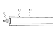
- the touch pen disclosed in Patent Document 2 has been previously proposed by the present applicant, and a conductive material is coated on each one of the fibers whose tip is tapered, as shown in FIG. It has a tip 51 formed by bundling, and a main shaft base 52 for holding the tip 51.
- the main shaft base 52 is covered with a conductive member 53. According to the touch pen having such a configuration, it can be used like a general writing pen, and so-called analog input such as drawing while changing the line width can be performed from the touch panel.
- Patent Document 2 as disclosed in FIG. 9, the disclosure of the touch pen having the tip of the tip end 51 sharpened is disclosed, and the feeling of use is improved, specifically, the ease of spreading the tip 51 at the time of input.
- the configuration for improving (feeling of use) has not been considered. Therefore, even if the tip end of the tip 51 is sharpened, for example, if the tip of the tip 51 has the same waist strength (bending strength) as the root side, the writing pressure is intensified. If this is not done, the contact area of the tip portion 51 can not be expanded, and there is a problem that the feeling of use is bad.
- the waist strength (bending strength) on the root side is weaker than the tip of the tip 51, the tip is broken at the root without spreading and the tip 51 is released from the touch panel. There was a problem that it was difficult to return to the shape.
- the present invention has been made focusing on the above-mentioned points, and in a capacitance-type conductive brush pen for inputting coordinate information from a capacitance-type input surface, a slight change in writing pressure can be obtained. Accordingly, it is an object of the present invention to provide a conductive brush pen in which the spread of the contact area of the tip portion can be easily changed and the feeling in use is improved.
- a conductive brush pen is a capacitive conductive brush pen for inputting coordinate information from a capacitive input surface, and a plurality of single conductive pens.
- the conductive brush pen having a brush-like tip part having conductivity bundled with fibers and having a surface resistivity of 10 10 ⁇ / sq or less, the tip part is directed from the tip side toward the rear side
- the ratio of the bending strength at each position of 1 mm, 2 mm and 3 mm from the tip of the tip is 1: 1.40 to 5.00: 1.50 to 8.50. It is characterized in that it is formed in the range of
- the contact area of the tip can be easily changed in response to a slight change in writing pressure, and the feeling in use can be significantly improved. Further, since the bending strength ratio is predetermined, the shape of the ear tip can be restored immediately when the ear tip is separated from the input surface.
- the plurality of single fibers constituting the tip portion include tapered single fibers having a pointed tip.
- the waist strength bending strength
- the feeling of use can be improved.
- the tip portion has an enlarged diameter portion which is expanded in diameter along the brush axis direction from its tip end, and a straight body portion which extends rearward from the rear end of the expanded diameter portion, and the center portion of the tip portion It is desirable that a length dimension between the tip of the tip and the tip of the straight body portion is formed to be 1 mm or more. That is, since the enlarged diameter portion is formed to have a length of 1 mm or more in the brush axis direction, the contact area of the tip portion can be easily obtained even in a weak writing pressure (in response to a slight change in writing pressure). Can be expanded to improve the feeling of use.
- the contact area of the tip portion be 0.78 mm 2 or more when the input surface is brought into contact with a load of 0.05 N.
- the center and the base of the tip of the tip after the probe is brought into contact with one of the positions 1 mm, 2 mm and 3 mm from the tip of the tip and the probe is moved up and down 50 times at a speed of 2 mm / sec. It is desirable that the angle between the line connecting the centers of the two and the axis (center line) of the tip be within 30 degrees.
- the predetermined bending strength predetermined bending strength ratio
- the shape of the ear can be immediately restored when the ear is separated from the input surface, and moreover, the ear can be 50 Even after being turned up and down (50 times reciprocation), the shape of the tip portion can be recovered, and a conductive brush pen having a good return property can be obtained.
- the writing pressure is proportional to the magnitude of the writing pressure.
- FIG. 1 is a side view showing the whole of a capacitance-type conductive brush pen according to the present invention.
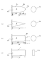
- FIG. 2 is a schematic view showing the shape of the tip portion of the capacitance-type conductive brush pen according to the present invention, and is a view showing the side surface of the tip portion and the base cross section of the tip portion.
- FIG. 3 is an enlarged side view of the tip of the conductive brush pen of FIG.
- FIG. 4 is an enlarged side view of single fibers (taper fibers and non-taper fibers) constituting a tip portion of the conductive brush pen of FIG. 1.
- FIG. 5 is a side view which shows typically the measuring apparatus used in order to measure the bending strength of a tip part in the Example.
- FIG. 5 is a side view which shows typically the measuring apparatus used in order to measure the bending strength of a tip part in the Example.
- FIG. 6 is a side view for explaining a measuring method by the measuring device of FIG.
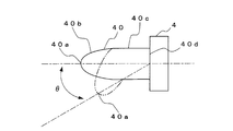
- FIG. 7 is a side view of the tip portion for explaining the method of measuring the return property.
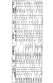
- FIG. 8 is a view showing the results of bending strength, strength ratio, spread state (contact area) of the tip, and returnability at positions 1 mm, 2 mm and 3 mm in the axial direction from the tip of the tip portion is there.
- FIG. 9 is a cross-sectional view schematically showing the configuration of a conventional brush-like touch pen.
- FIG. 1 is a side view showing the whole of the conductive brush pen according to the present invention
- FIG. 2 is a schematic view showing the shape of the tip portion of the capacitive type conductive brush pen according to the present invention. is there.
- FIG. 3 is an enlarged side view of the tip of the conductive brush pen of FIG.
- FIG. 4 is the side view to which the single fiber (a taper fiber and a non-taper fiber) which comprises the tip part which the electroconductive brush pen of FIG. 1 has is expanded.
- the capacitance type conductive brush pen 1 shown in FIG. 1 is an input device for inputting coordinate information from a touch panel (input surface) of a capacitance type input provided, for example, in a smartphone or a tablet type portable information terminal. is there.
- the conductive brush pen 1 includes a body shaft 2 which is a shaft portion gripped by an operator, and a brush-like tip 3 attached to the tip of the body shaft 2 and brought into contact with the touch panel (not shown). .
- the body shaft 2 and the tip 3 have electrical conductivity, and are connected in a state of being electrically connected to each other.
- the tip portion 3 is formed in a state in which single fibers of soft synthetic resin are bundled and the bundle rear end is fixed by the locking plate 4 and, as shown in FIGS. 1 and 3, the tip portion 3a and the outer peripheral surface taper It has a tapered portion 3b which is formed in a shape (conical shape) and formed so as to gradually increase in diameter, and a straight body portion 3c having a constant diameter.
- the tip 3 has a circular cross section of the base 3d of the tip 3 and the tip 3a is formed in a curved shape, the tip 3 (b).
- the tip portion 3 is formed in a conical shape as a whole, and the tip portion is formed in a cylindrical shape as a whole as shown in (c) (a chamfered portion 3e is formed on the tip 3a). As shown in 3 and (d), the tip portion 3 may be formed in a columnar shape having a rectangular cross section as a whole. However, considering that the contact area of the tip portion is easily changed in proportion to the magnitude of the writing pressure, the tip portion 3a as shown in FIG. 1 and FIGS. 2 (a) and 2 (b) It is desirable that the shape of the tip portion 3 has a tapered shape or a curved surface-shaped enlarged diameter portion 3b whose diameter gradually expands along the brush axis direction.
- the material of the single fiber constituting the tip 3 is polyester resin such as polybutylene terephthalate, polyethylene terephthalate, polytrimethylene terephthalate, polyethylene naphthalate, polybutylene naphthalate, polyolefin resin such as polyethylene, polypropylene, nylon 6 Polyamide resins such as nylon 610 and nylon 612, acrylic resins, polyurethane resins, polyacetal resins, polycarbonate resins, polyether resins, polyphenylene resins and polyvinyl resins are used.
- polyester resin such as polybutylene terephthalate, polyethylene terephthalate, polytrimethylene terephthalate, polyethylene naphthalate, polybutylene naphthalate, polyolefin resin such as polyethylene, polypropylene, nylon 6 Polyamide resins such as nylon 610 and nylon 612, acrylic resins, polyurethane resins, polyacetal resins, polycarbonate resins, polyether resins, polyphenylene
- the number of single fibers constituting the tip portion 3 can be set as appropriate, but generally, about 100 to 5000 fibers can be suitably used. If the number is large, the diameter of the tip 3 becomes large and thin lines can not be drawn. On the other hand, if the number is small, the diameter of the tip 3 becomes small and thick lines can not be drawn. This degree is preferred.
- the non-taper fiber 31 which has the end surface 31a without tipping, or a taper part in which the tip was tapered
- a tapered fiber 32 having 32a is used.
- the non-taper fiber 31 is formed in the diameter of 0.015 mm or more and 0.25 mm or less.
- the tapered fibers 32 are formed such that the diameter of the straight body portion 32c is in the range of 0.015 mm or more and 0.25 mm or less.
- the diameter of the tip portion 32b of the tapered fiber 32 is smaller than the diameter of the straight body portion 32c and smaller than 0.05 mm.
- the tapered portion 32a of the tapered fiber 32 is formed to have a length A of at least 1 mm or more from the tip portion 32b.
- the tip portion 3 is formed by mixing only the non-tapered fibers 31 or only the tapered fibers 32, or the non-tapered fibers 31 and the tapered fibers 32.
- the waist strength is increased toward the rear side from the tip 3 a of the tip 3 shown in FIG. 3 to the tapered portion 3 b and the straight body 3 c. Strength) can be made strong, and the feeling in use can be improved. Therefore, it is preferable that the tip portion 3 contains at least 50% or more of the number of tapered fibers 32.
- the strength of the hips 3 at the 1 mm position, 2 mm position and 3 mm position along the axial direction (backward) from the tip 3a of the tip 3 as shown in FIG. increases sequentially, and assuming that the bending strength at the position of 1 mm is 1, the bending strength at the position of 2 mm is 1.40 to 5.00, and the bending strength at the position of 3 mm is 1.50 to It is formed to have an intensity ratio of 8.50.
- the strength of the waist refers to the strength measured by the measurement method described in the examples.
- the material of the single fiber in the tip portion 3 in order to form the tip portion 3 at the bending strength ratio, the material of the single fiber in the tip portion 3, the diameter of the single fiber, the mixing ratio of the non-taper fiber and the tapered fiber, the length dimension of the tapered portion of the tapered fiber, It is carried out by setting the number of single fibers, the shape of the tip portion, the diameter of the tip portion, and the length dimension.
- the contact area of the tip 3 can be easily expanded according to the writing pressure, and the tip 3 from the touch panel (input surface) When it is released, the shape of the tip 3 can be restored immediately (the shape of the tip 3 can be recovered immediately).
- a conductive film is formed on each of the single fibers 30 constituting the tip 3 by being coated with a conductive material.
- this conductive film is formed in order to express fixed conductivity as the whole brush, it is not necessary to form a conductive film on all the single fibers which constitute the tip portion 3, and a predetermined number of conductive films are required.
- the conductive film may be formed on the monofilament of When the tip 3 is formed by mixing the non-taper fibers 31 and the taper fibers 32, the non-taper fibers 31 on which the conductive film is formed and the taper fibers 32 on which the conductive film is not formed are mixed. Alternatively, the non-taper fibers 31 in which the conductive film is not formed and the tapered fibers 32 in which the conductive film is formed may be mixed.
- a conductive polymer having a heterocyclic compound or an aromatic hydrocarbon in its molecular structure is preferably used, for example, the conductive polymer As polypyrrole, polythiophene, polyethylenedioxythiophene, polyisothianaphthene or polyacene is used.
- the surface of each single fiber 30 is coated with a coating of a conductive polymer of the polypyrrole, polythiophene, polyethylenedioxythiophene, polyisothianaphthene or polyacene on each single fiber 30 constituting the tip 3.
- a conductive film of 100 ⁇ m or less can be formed.
- the conductive polymer may be coated by, for example, immersing the conductive material in a monomer-containing treatment solution, polymerizing the conductive polymer on its surface, or coating the conductive polymer dispersed in a binder, etc. Can be mentioned.
- the surface resistivity of the conductive film on the surface of each single fiber 30 formed by such a method is set to 10 10 ⁇ / sq or less by adjusting the film thickness and the like of the conductive film. As described above, by setting the surface resistivity of the conductive film on the surface of each single fiber 30 to 10 10 ⁇ / sq or less, it is detected by the touch panel of the capacitance type input, and as an input device for inputting coordinate information It can be used.
- the conductive single fiber 30 is not limited to a single fiber having a conductive film formed by coating the conductive material as described above, and, for example, carbon black, graphite, carbon nanotubes, metal particles, etc. It is also possible to use a conductive fiber prepared by kneading a so-called conductive material prepared from a dispersed resin solution, a molten resin or the like. Also, the surface is coated with a so-called conductive material such as a conductive fiber obtained by chemically bonding copper sulfide to a synthetic resin (single fiber), or a conductive fiber formed by plating silver or copper on a synthetic resin (single fiber). The formed conductive fiber can also be used.
- the contact area of the tip is set to be 0.78 mm 2 or more. By doing this, it is configured such that a contact area in which coordinates can be detected on the touch panel can be secured even with a weak writing pressure.
- the tip 3 When the tip 3 is brought into contact with the input surface by applying a load of 0.05 N, the tip 3 sets the contact area of the tip 3 to be 0.78 mm 2 or more.
- the cross section of the base 3d of the tip 3 is circular, and the tip 3 (having the tapered portion 3b) formed in a tapered shape from the tip 3a, FIG.
- the cross section of the base 3d of the tip 3 is circular, and the tip 3 (having the curved surface portion 3b) formed in a curved shape from the tip 3a, as shown in FIG. 2 (b)
- the tip 3 is formed in a conical shape (taper shape) as a whole. That is, it is preferable to have an enlarged diameter portion 3b (a tapered portion, a curved surface portion) whose diameter is expanded along the brush axis direction from the tip.
- L3 the length dimension of the curved-surface-shaped part 3b may be formed in 1 mm or more. That is, it is preferable that a length dimension of the enlarged diameter portion 3b (a tapered shape portion, a curved surface shape portion) whose diameter is expanded along the brush axis direction from the tip end be 1 mm or more.
- the main shaft 2 is not particularly limited as long as it has conductivity on the surface thereof, but for example, a synthetic resin shaft containing carbon black, metal fine particles, etc. or the synthetic resin shaft surface is plated A thing or the thing in which the whole was formed with electroconductive metal etc. can be used.
- the surface of a non-conductive shaft made of, for example, a synthetic resin shaft may be coated with a conductive polymer as described above. That is, by forming the main body shaft 2 in such a manner, the main body shaft 2 can be made conductive.
- the strength of the waist on the rear side of the tip end side (bending strength) at least at the tip 3 from the tip to the position of 3 mm along the brush axis ) Is formed to be large.
- the tip 3 can be expanded with the contact area required for coordinate detection, and the area where the tip 3 easily spreads in proportion to the strength of the writing pressure (contact Since the area can be changed, the feeling of use can be significantly improved.
- the shape of the ear tip 3 can be restored immediately (it can be restored to the original shape).
- the tip portion 3 is the tapered portion 3b whose diameter is expanded in the axial direction from the tip 3a to at least 3 mm
- the brush pen 1 according to the present invention is not limited thereto.
- the tapered portion 3b may be formed to a position of at least 1 mm along the axial direction from the tip portion 3a, and the straight body 3c may be formed on the rear side thereof.
- the tip portion having a plurality of configurations including the configuration shown in the above-described embodiment was used as an object to be measured, and the conductive brush pen according to the present invention was verified.
- the bending strength ratio at 1 mm, 2 mm and 3 mm positions is determined in the axial direction from the tip of the tip, and the spread state of the tip, tip It verified about the returnability and the feeling of use which restore the shape of the part.
- the measuring apparatus shown in FIG. 5 includes a stand unit 21 which is an elevating mechanism erected on a base 20.
- the stand 21 is formed with a groove 21a extending linearly in the vertical direction, and the slider 22 is provided to be movable up and down along the groove 21a by a screw mechanism or the like.
- the elevating mechanism MX-500N manufactured by IMADA can be used.
- a load meter 26 is mounted on the slider 22 to measure the load applied to the probe 25.
- this load meter 26 MODL DS2-2N manufactured by IMADA can be used.
- the probe 25 of the load meter 26 is disposed so that the tip thereof protrudes laterally (horizontally), and before load measurement, as shown in FIG.
- the tip portion 40 is disposed such that the tip portion 40a of the tip portion 40 which is the measurement object is located below the tip surface 25a.
- the fixing jig 28 is configured to be movable in the horizontal direction, and is configured to be able to change the initial position of the tip portion 40.
- the vertical direction of the fixing jig 28 is fixed so as not to move.
- the probe 25 of the load meter 26 is configured to be movable in the vertical direction, and is configured not to move in the horizontal direction. Then, by moving the fixing jig 28 in the horizontal direction, the measuring element 25 is positioned directly above the position of the predetermined distance d (one of 1 mm, 2 mm, 3 mm) along the axial direction from the tip 40 a of the tip 40.
- the front end face 25a of is positioned so as to set its position as an initial position.
- the load meter 26 when measuring the bending strength of the tip portion 40, first, the load meter 26 is lowered together with the slider 22 from the state of the initial position shown in FIG. As a result, the measuring element 25 of the load meter 26 descends, and as shown in FIG. 6B, the measuring element 25 comes in contact with the tip end side of the tip 40 from the upper side, and pushes the tip end side of the tip 40 It becomes. Further, the tip end side of the tip portion 40 is pressed against the tip surface 25 a of the measuring element 25. In this state, a predetermined load F in the horizontal direction acts on the measurer 25, and a load measurement value is displayed on the display window 26 a of the load meter 26. The maximum value of this measurement value is taken as the value of bending strength. When the load meter 26 further descends, as shown in FIG. 6C, the tip portion 40 is separated from the probe 25.
- a paper is placed on a weighing scale, and an ink which is resistant to bleeding and fainting is sufficiently contained in the tip portion (brush). Then, lightly place the inked brush tip on the paper on the weighing scale. Load the tip of the brush (pen) until the scale reaches 0.05 N. Thereafter, the paper is cut out only at the portion to which the ink is attached, the weight thereof is measured, and the contact area is calculated in comparison with the weight of the inked paper whose area is known in advance. Specifically, ink is previously applied to paper having an area of, for example, 1 cm 2 , and its weight is measured.
- the weight of the paper of the cut-off inked portion when the load of 0.05 N is applied is measured.
- the area of the paper of the cut-out inked portion, ie, the contact by comparing the weight of the paper with the inked portion and the weight of the paper having an area of 1 cm 2 with the ink, Calculate the area.
- the reversibility for recovering the shape of the tip portion is to verify the restorability of the tip portion 3 and the recovery property of the shape of the tip portion 3 when used repeatedly, and using the measuring device schematically shown in FIG. went. That is, the measuring element 25 of the load meter 26 descends, and as shown in FIG. 6B, the measuring element 25 contacts from the upper side to the tip end side of the tip 40 and pushes and bends the tip end of the tip 40 As shown in FIG. 6 (c), it moves to the lower position of the tip portion 40.
- the gauge head 25 of the load meter 26 ascends, pushes and bends the tip end of the tip portion 40, and moves to a position above the tip portion 40.
- the measuring element 25 was lowered and raised once at a speed of 2 mm / sec, and the degree of deformation of the tip portion 40 after 50 consecutive passes (50 reciprocations) was measured.
- the tip surface 25a of the tracing stylus 25 is positioned at a predetermined distance d (3 mm) along the axial direction from the tip 40a of the tip 40
- the arrangement is taken as the initial position.
- the probe 25 is lowered and raised 50 times (50 reciprocations) continuously at a speed of 2 mm / sec without contacting the probe 25 (in a state where no load is applied).
- the angle ⁇ between the line connecting the center of the tip 40a of the tip 40 and the center of the base 40d of the tip 40 with the axis (center line) of the tip 40 was measured.
- FIG. 1 the angle between the line connecting the center of the tip 40a of the tip 40 and the center of the base 40d of the tip 40 with the axis (center line) of the tip 40 was measured.
- reference numeral 40 b denotes a tapered portion of the tip portion 40
- reference numeral 40 d denotes a straight body portion of the tip portion 40.
- Example 1 As a raw material of a tip portion (single fiber), it is 100% without mixing non-taper fibers with a taper fiber in which a taper portion with a length A of 1 mm is formed using polybutylene terephthalate having a diameter of 0.15 mm. Using. Further, each single fiber is coated with a conductive polymer of 1 ⁇ m, and a bundle of 3,000 single fibers is formed, and as shown in FIG. 3, the diameter of the tip 3a and the outer peripheral surface formed in a tapered shape (conical shape) The tip portion 3 is formed to have a tapered portion 3b whose diameter gradually increases and a straight body portion 3c having a constant diameter.
- the tip 3 is formed such that the diameter of the base 3d of the tip 3 is 8 mm, the total length L1 is 35 mm, the length L2 of the straight body 3c is 25 mm, and the length L3 of the tapered portion 3b is 10 mm. Then, using the measuring device described above, measure the bending strength at a position of 1 mm, 2 mm and 3 mm in the axial direction from the tip of the tip, and further determine the bending strength ratio, State of contact (contact area), returnability to recover the shape of the tip, and feeling in use were examined. The results are shown in FIG.
- Example 2 As shown to Fig.2 (a), the cross section of the base part 3d of the tip part 3 was circular, Comprising: The tip part 3 by which the front-end
- Example 3 As shown in FIG. 2 (b), a tip 3 which is formed in a conical shape as a whole is used.
- the diameter of the base 3d of the tip 3 is 8 mm, and the total length L1 is 35 mm.
- the other conditions were the same as in Example 1.
- the bending strength was measured in the same manner as in Example 1, and the bending strength ratio was further determined, and the state of spread of the tip (contact area) at that time, the returnability to recover the shape of the tip, and the feeling of use were verified. The results are shown in FIG.
- Example 4 As shown in FIG.2 (c), the tip 3 which the whole was formed in the column shape was used. The diameter of the base of the tip 3 was 8 mm, and the total length L1 was 35 mm. Further, the length L3 of the chamfered portion 3e at the tip end is 1 mm, and L2 is 34 mm. The other conditions were the same as in Example 1. Then, the bending strength was measured in the same manner as in Example 1, and the bending strength ratio was further determined, and the state of spread of the tip (contact area) at that time, the returnability to recover the shape of the tip, and the feeling of use were verified. The results are shown in FIG.
- the cross section of the base part 3d of the tip part 3 was circular, Comprising: The tip part 3 by which the front-end
- the diameter of the base 3d of the tip 3 is 3 mm
- the total length L1 is 15 mm
- the length L2 of the straight body 3c is 10 mm
- the length of the curved surface 3b is 5 mm.
- 30% of taper fibers of 0.10 mm in diameter were mixed.
- a tapered fiber with a diameter of 0.25 mm was 8 mm from the tip, and a tapered fiber with a diameter of 0.10 mm was a fiber in which a tapered portion 32a having a length A of 5 mm was formed from the tip.
- the other conditions were the same as in Example 2.
- the bending strength was measured in the same manner, and the bending strength ratio was further determined, and the spread state (contact area) of the tip portion at that time, the returnability to recover the shape of the tip portion and the feeling of use were verified. The results are shown in FIG.
- Example 6 In the ear portion in which the base diameter of the tip 3 in Example 3 is changed to 10 mm and the total length L1 is changed to 40 mm, and the taper fiber with a diameter of 0.10 mm is mixed with 45% and the taper fiber with a diameter of 0.05 mm is mixed changed.
- the taper fiber of 0.10 mm in diameter and the taper fiber of diameter 0.05 mm used the fiber in which the taper part 32a of length A 3 mm was formed from the tip.
- the other conditions were the same as in Example 3.
- Example 3 Then, the bending strength was measured in the same manner as in Example 3, and the bending strength ratio was determined, and the state of spread of the tip (contact area) at that time and the returnability and feeling of use for recovering the shape of the tip were verified. The results are shown in FIG.
- Example 7 The diameter of the base 3d of the tip 3 in Example 4 was changed to 5 mm, and the tip was made by mixing 50% of taper fibers with a diameter of 0.07 mm and 50% of non-taper fibers with a diameter of 0.07 mm. .
- the tapered fiber having a diameter of 0.07 mm was a fiber in which a tapered portion 32a having a length A of 3 mm was formed from the tip.
- the other conditions were the same as in Example 4.
- the bending strength was measured in the same manner as in Example 4, and the bending strength ratio was determined, and the state of spread of the tip (contact area) at that time, the returnability to recover the shape of the tip, and the feeling of use were verified. The results are shown in FIG.
- a material of the tip As a material of the tip (single fiber), a polybutylene terephthalate having a diameter of 0.07 mm is used, and a tapered fiber in which a tapered portion 32a having a length A of 10 mm from the tip is formed is 100 without mixing non-taper fibers. %Using. Each single fiber was coated with a conductive polymer at a thickness of 1 ⁇ m. In addition, 500 single fibers were bundled, and as shown in FIG. 2D, a tip portion formed in a columnar shape having a rectangular cross section was formed.
- the tip 3 having the width (longitudinal and lateral) of the base 3 d of the tip 3 of 8 mm ⁇ 1 mm and the total length L1 of 35 mm was formed. Then, in the same manner as in Example 1, the bending strength at a position of 1 mm, a position of 2 mm, and a position of 3 mm in the axial direction from the tip of the tip is measured using the above-mentioned measuring device. It asked about the expansion state (contact area) of the tip part at that time, and the return nature and the feeling of use which restore the shape of a tip part. The results are shown in FIG.
- Example 2 The tip portion under the same conditions as in Example 6 was used except that a non-taper single fiber with a diameter of 0.10 mm was used instead of the taper single fiber with a diameter of 0.05 mm mixed in 55% in Example 6. Then, the bending strength was measured in the same manner as in Example 6, and the bending strength ratio was determined, and the state of spread of the tip (contact area) at that time, the returnability to recover the shape of the tip, and the feeling of use were verified. The results are shown in FIG.
- Example 4 (Comparative example 3) In Example 4, instead of 100% of the tapered fibers having a diameter of 0.15 mm, a point portion in which 50% of tapered fibers having a diameter of 0.28 mm and 50% of tapered fibers having a diameter of 0.15 mm were mixed was used.
- the taper fiber 32 having a length A of 5 mm was formed 5 mm from the tip of the taper fiber having a diameter of 0.15 mm and the taper fiber having a diameter of 0.28 mm, and the tip having the same conditions as Example 4 was used.
- Example 4 (Comparative example 4) In Example 1, instead of the tapered fiber 100% having a diameter of 0.15 mm, a point portion in which 50% of a tapered fiber having a diameter of 0.05 mm and 50% of a non-taper single fiber having a diameter of 0.01 mm were mixed was used.
- the taper fiber 32a of length A of 3 mm was formed from the tip, and the tip of the same conditions as Example 1 was used for the taper fiber whose diameter is 0.05 mm. Then, the bending strength was measured in the same manner as in Example 1, and the bending strength ratio was further determined, and the state of spread of the tip (contact area) at that time, the returnability to recover the shape of the tip, and the feeling of use were verified. The results are shown in FIG.
- the tip of the brush was easily spread by adjusting the user's force, the degree of spread of the tip could be adjusted, and the feeling in use was good.
- Comparative Example 1 since the bending strength at each position was similar, it was difficult to adjust the spread of the hair tips, and the feeling in use was bad. In addition, when a load of 0.05 N was applied for contact, the contact area of the tip portion was 0.78 mm 2 or less, which was not suitable as an input device for a capacitive touch panel. Moreover, in Comparative Example 2, the bending strength rapidly increased in 2 mm or more from the tip, the hair tip was difficult to spread, and the feeling in use was bad. Furthermore, in Comparative Example 3, since the bending strength at each position was similar, it was difficult to adjust the spread of the hair tips, and the feeling in use was bad. Furthermore, in Comparative Example 4, since the bending strength at each position is similar, the spreading of the hair tip is difficult to prepare, and the fiber diameter is thin and can not withstand bending and the returnability is poor.
- the tip portion is formed so as to increase the bending strength from the tip side toward the back side, and the tip end of the tip portion Feeling in use becomes good because the ratio of the bending strength in each position of 1 mm and 2 mm and 3 mm is formed in the range of 1: 1.40 to 5.00: 1.50 to 8.50. It has been found.
- the contact areas of Examples 1 to 7 when the load of 0.05 N is applied and the contact is made, the contact area of the above-mentioned tip portion becomes 0.78 mm 2 or more. It can be used as an input device of a capacitive touch panel.
- the reversibility of Examples 1 to 7 restores the shape of the tip within the range of 30 degrees even after the measuring element brought into contact with the tip is moved up and down 50 times. It was found that the feeling of use was good.
Landscapes
- Engineering & Computer Science (AREA)
- General Engineering & Computer Science (AREA)
- Theoretical Computer Science (AREA)
- Human Computer Interaction (AREA)
- Physics & Mathematics (AREA)
- General Physics & Mathematics (AREA)
- Pens And Brushes (AREA)
Abstract
静電容量型の入力面から座標情報を入力するための静電容量型の筆ペンにおいて、筆圧に応じて穂先部の繊維の拡がりを容易にコントロールすることができ、使用感を向上する。 複数の単繊維が束ねられた導電性を有する筆状の穂先部3を備え、表面抵抗率が1010Ω/sq以下の導電性を有する導電性筆ペンにおいて、前記穂先部3は、先端側から後方側に向かって曲げ強度が大きくなるように形成され、かつ前記穂先部3先端3aから1mmと2mmと3mmの夫々の位置における曲げ強度の比率が、1:1.40~5.00:1.50~8.50の範囲で形成されている。
Description
本発明は導電性筆ペンに関し、例えば、携帯型情報端末などが備える静電容量型のタッチパネルに座標情報を入力するための静電容量型の導電性筆ペンに関する。
スマートフォンやタブレット型PCなどにおいては、その入力装置として例えば静電容量型のタッチパネルが多く用いられている。
この静電容量型のタッチパネルでは、指示体である指先やタッチペンの接触により、所定の静電容量を発生させ、二次元格子状に配列された複数の電極により静電容量の変化を検出してパネル上の座標を特定している。
この静電容量型のタッチパネルでは、指示体である指先やタッチペンの接触により、所定の静電容量を発生させ、二次元格子状に配列された複数の電極により静電容量の変化を検出してパネル上の座標を特定している。
前記タッチパネルへの指示体として、例えば図形や文字を描く場合には、指先よりも細かい接触面積での入力が可能なタッチペンが便利である。
このタッチペンは、例えば特許文献1に開示されるように、導電性を持つ把持部と、その把持部に電気的に接続する導電性を有するペン先とを備えている。即ち、把持部を持つ人体とペン先とが電気的に導通しているため、ペン先とタッチパネルとの接触部において静電容量の変化を生じさせることができ、パネル上の座標が検出可能となる。
このタッチペンは、例えば特許文献1に開示されるように、導電性を持つ把持部と、その把持部に電気的に接続する導電性を有するペン先とを備えている。即ち、把持部を持つ人体とペン先とが電気的に導通しているため、ペン先とタッチパネルとの接触部において静電容量の変化を生じさせることができ、パネル上の座標が検出可能となる。
ところで、前記タッチペンにあっては、ペン先が導電性を有し、所定以上の接触面積を確保できるものであれば、その形状に拘わらずタッチパネルへの指示体として使用することができる。そのため、ペン先が筆状であってもよく、その場合、線を描く際に、例えば細い線から太い線、或いは太い線から細い線へと線幅を変化させることも可能であり、ペン先の幅が固定されたタッチペンに比べて、描画や文字の表現力の幅を格段に向上することができる。
前記筆状のペン先を持つタッチペン(導電性筆ペン)については、例えば特許文献2に開示されている。特許文献2に開示されるタッチペンは、本出願人が先に提案したものであり、先端がテーパ状に尖った繊維一本一本に導電性材料を被覆し、それを図9に示すように束ねて形成された穂先部51と、この穂先部51を保持する本体軸基材52とを有している。また、本体軸基材52は、導電性を有する部材53で被覆されている。
このような構成のタッチペンによれば、一般的な筆ペンのように用いることができ、線幅を変更しながら描くようないわゆるアナログ的な入力をタッチパネルから行うことができるものとなっている。
このような構成のタッチペンによれば、一般的な筆ペンのように用いることができ、線幅を変更しながら描くようないわゆるアナログ的な入力をタッチパネルから行うことができるものとなっている。
しかしながら、特許文献2にあっては、図9に示すように穂先部51の先端を尖らせたタッチペンの開示にとどまり、使用感の向上、具体的には入力時における穂先部51の拡がり易さ(使用感)を向上するための構成については検討されていなかった。
そのため、前記穂先部51の先端を尖らせた形状であっても、例えば、穂先部51の先端部が根元側と同様の腰の強さ(曲がり強度)である場合には、筆圧を強めにしなければ穂先部51の接触面積が拡がらず、使用感が悪いという課題があった。
一方、穂先部51の先端よりも根元側の腰の強さ(曲がり強度)が弱い場合には、先端が拡がらずに根元側で折れ、穂先部51をタッチパネルから離した際に、元の形状に戻り難いという課題があった。
そのため、前記穂先部51の先端を尖らせた形状であっても、例えば、穂先部51の先端部が根元側と同様の腰の強さ(曲がり強度)である場合には、筆圧を強めにしなければ穂先部51の接触面積が拡がらず、使用感が悪いという課題があった。
一方、穂先部51の先端よりも根元側の腰の強さ(曲がり強度)が弱い場合には、先端が拡がらずに根元側で折れ、穂先部51をタッチパネルから離した際に、元の形状に戻り難いという課題があった。
本発明は、前記した点に着目してなされたものであり、静電容量型の入力面から座標情報を入力するための静電容量型の導電性筆ペンにおいて、わずかな筆圧の変化に応答して、穂先部の接触面積の拡がりを容易に変化させることができ、使用感を向上した導電性筆ペンを提供することを目的とする。
前記した課題を解決するために、本発明に係る導電性筆ペンは、静電容量型の入力面から座標情報を入力するための静電容量型の導電性筆ペンであって、複数の単繊維が束ねられた導電性を有する筆状の穂先部を備え、表面抵抗率が1010Ω/sq以下の導電性を有する導電性筆ペンにおいて、前記穂先部は、先端側から後方側に向かって曲げ強度が大きくなるように形成され、かつ前記穂先部先端から1mmと2mmと3mmの夫々の位置における曲げ強度の比率が、1:1.40~5.00:1.50~8.50の範囲で形成されていることに特徴を有する。
このように構成することにより、わずかな筆圧の変化に応答して、容易に穂先部の接触面積を変化させることができるため、使用感を格段に向上することができる。また、所定の曲げ強度比を備えているため、入力面から穂先部を離した際、直ぐさま穂先部の形状を元に戻すことができる。
また、前記穂先部を構成する複数の単繊維は、先端が尖ったテーパ形状の単繊維を含むことが望ましい。
このようにテーパ形状の単繊維を含むことにより、穂先部の先端から筆軸方向に沿って後方側ほど腰の強さ(曲げ強度)を強くすることができ、使用感を向上させることができる。
このようにテーパ形状の単繊維を含むことにより、穂先部の先端から筆軸方向に沿って後方側ほど腰の強さ(曲げ強度)を強くすることができ、使用感を向上させることができる。
また、前記穂先部は、その先端から筆軸方向に沿って拡径する拡径部と、前記拡径部の後端から後方側に延びる直胴部とを有し、前記穂先部の中心部の先端と前記直胴部の先端との間の長さ寸法が、1mm以上に形成されていることが望ましい。即ち、前記拡径部が筆軸方向に1mm以上の長さに形成されることにより、弱い筆圧であっても(わずかな筆圧の変化に応答して)、容易に穂先部の接触面積を拡げることができ、使用感を向上させることができる。
また、前記入力面に対して、0.05Nの荷重をかけて接触させた際、前記穂先部の接触面積が0.78mm2以上となるように形成されていることが望ましい。このようにすることで、弱い筆圧(軽い筆圧)で入力しても検知することが可能となり、静電容量型の入力装置として好適に用いることができる。
また、前記穂先部先端から1mmと2mmと3mmのいずれかの位置に測定子を接触させ、測定子を速度2mm/秒で50回上下させた後の前記穂先部の先端部の中心と基底部の中心を結ぶ線と、穂先部の軸線(中心線)とのなす角度が30度以内であることが望ましい。
上記したように所定の曲げ強度(所定の曲げ強度比)を備えているため、入力面から穂先部を離した際、直ぐさま穂先部の形状を元に戻すことができ、しかも穂先部を50回上下(50回往復)させた後にあっても、穂先部の形状を回復させることができ、戻り性が良好な導電性筆ペンを得ることができる。
上記したように所定の曲げ強度(所定の曲げ強度比)を備えているため、入力面から穂先部を離した際、直ぐさま穂先部の形状を元に戻すことができ、しかも穂先部を50回上下(50回往復)させた後にあっても、穂先部の形状を回復させることができ、戻り性が良好な導電性筆ペンを得ることができる。
本発明によれば、静電容量型の入力面から座標情報を入力するための静電容量型の導電性筆ペンにおいて、わずかな筆圧の変化に応答して、筆圧の大きさに比例して穂先部の接触面積の拡がりを容易に変化させることができ、使用感を向上した導電性筆ペンを得ることができる。
以下、本発明の実施の形態を図1乃至図4に基づき説明する。尚、図1は、本発明に係る導電性筆ペンの全体を示す側面図であり、図2は、本発明に係る静電容量型の導電性筆ペンの穂先部の形状を示す概略図である。また、図3は、図1の導電性筆ペンの先端を拡大した側面図である。また、図4は、図1の導電性筆ペンが有する穂先部を構成する単繊維(テーパ繊維及び非テーパ繊維)を拡大した側面図である。
図1に示す静電容量型の導電性筆ペン1は、例えばスマートフォン、タブレット型の携帯情報端末などが備える静電容量型入力のタッチパネル(入力面)から座標情報を入力するための入力機器である。
この導電性筆ペン1は、作業者が把持する軸部である本体軸2と、本体軸2の先端に取り付けられ、前記タッチパネル(図示せず)に接触させる筆状の穂先部3とを備える。前記本体軸2と穂先部3とは、それぞれ導電性を有しており、また、互いに電気的に導通する状態に連結されている。
この導電性筆ペン1は、作業者が把持する軸部である本体軸2と、本体軸2の先端に取り付けられ、前記タッチパネル(図示せず)に接触させる筆状の穂先部3とを備える。前記本体軸2と穂先部3とは、それぞれ導電性を有しており、また、互いに電気的に導通する状態に連結されている。
この穂先部3は、軟質合成樹脂の単繊維を束ね、係止板4で束後端を固定した状態に形成されており、図1、3に示すように、先端部3aと、外周面テーパ形状(円錐形状)に形成され、直径が徐々に大きくなるように形成されたテーパ部3bと、直径が一定の直胴部3cとを備えている。
ところで、この穂先部3は、図2(a)に示すように、穂先部3の基底部3dの断面が円形であって、先端部3a側が曲面形状に形成された穂先部3、(b)に示すように全体が円錐形状に形成されている穂先部3、(c)に示すように全体が円柱状(先端部3aには面取り部3eが形成されている)に形成されている穂先部3、(d)に示すように全体が断面矩形状の柱状に形成されている穂先部3であっても良い。
但し、筆圧の大きさに比例して、容易に穂先部の接触面積を変化させる点を考慮すると、前記図1、図2(a),(b)に示すような、その先端部3aから筆軸方向に沿って直径が徐々に広がるテーパ形状あるいは曲面形状の拡径部3bを有する穂先部3の形状であることが望ましい。
ところで、この穂先部3は、図2(a)に示すように、穂先部3の基底部3dの断面が円形であって、先端部3a側が曲面形状に形成された穂先部3、(b)に示すように全体が円錐形状に形成されている穂先部3、(c)に示すように全体が円柱状(先端部3aには面取り部3eが形成されている)に形成されている穂先部3、(d)に示すように全体が断面矩形状の柱状に形成されている穂先部3であっても良い。
但し、筆圧の大きさに比例して、容易に穂先部の接触面積を変化させる点を考慮すると、前記図1、図2(a),(b)に示すような、その先端部3aから筆軸方向に沿って直径が徐々に広がるテーパ形状あるいは曲面形状の拡径部3bを有する穂先部3の形状であることが望ましい。
この穂先部3を構成する単繊維の素材として、ポリブチレンテレフタレート、ポリエチレンテレフタレート、ポリトリメチレンテレフタレート、ポリエチレンナフタレート、ポリブチレンナフタレート等のポリエステル系樹脂、ポリエチレン、ポリプロピレン等のポリオレフィン系樹脂、ナイロン6,ナイロン610、ナイロン612等のポリアミド系樹脂、アクリル系樹脂、ポリウレタン系樹脂、ポリアセタール系樹脂、ポリカーボネート系樹脂、ポリエーテル系樹脂、ポリフェニレン系樹脂、ポリビニル系樹脂が用いられている。
この単繊維としては、直径が0.015mm~0.25mm程度のものが適度な弾力が得られると共に、曲がりや折れなどの抑制効果も有しており、筆ペンの穂先として好適に利用することができる。このように適度な弾力を備えているため、入力面から穂先部を離した際、直ぐさま穂先部の形状を元に戻すことができる。
この単繊維としては、直径が0.015mm~0.25mm程度のものが適度な弾力が得られると共に、曲がりや折れなどの抑制効果も有しており、筆ペンの穂先として好適に利用することができる。このように適度な弾力を備えているため、入力面から穂先部を離した際、直ぐさま穂先部の形状を元に戻すことができる。
また、穂先部3を構成する単繊維の本数は、適宜設定することができるが、通常100本~5000本程度のものを好適に利用することができる。本数が多いと穂先部3の直径が大きくなり、細い線が描くことができず、一方、本数が少ないと穂先部3の直径が小さくなり、太い線が描くことができないため、100本~5000本程度が好ましい。
この穂先部3を構成する各単繊維30としては、図4で拡大した模式図で示すように、先端が尖らずに端面31aを有する非テーパ繊維31、あるいは先端がテーパ状に尖ったテーパ部32aを有するテーパ繊維32が用いられる。
尚、非テーパ繊維31は、直径が0.015mm以上0.25mm以下の範囲で形成されている。また、前記テーパ繊維32は、直胴部32cの直径が0.015mm以上0.25mm以下の範囲で形成されている。そしてまた、前記テーパ繊維32の先端部32bの直径は、前記直胴部32cの直径よりも小さく、かつ0.05mmよりも小さく形成されている。また、前記テーパ繊維32のテーパ部32aは、先端部32bから少なくとも1mm以上の長さAに形成されている。
尚、非テーパ繊維31は、直径が0.015mm以上0.25mm以下の範囲で形成されている。また、前記テーパ繊維32は、直胴部32cの直径が0.015mm以上0.25mm以下の範囲で形成されている。そしてまた、前記テーパ繊維32の先端部32bの直径は、前記直胴部32cの直径よりも小さく、かつ0.05mmよりも小さく形成されている。また、前記テーパ繊維32のテーパ部32aは、先端部32bから少なくとも1mm以上の長さAに形成されている。
前記穂先部3は、非テーパ繊維31のみ、あるいはテーパ繊維32のみ、また非テーパ繊維31及びテーパ繊維32を混在させて形成される。
但し、前記穂先部3にテーパ繊維32を多く含むことにより、図3に示す穂先部3の先端部3aからテーパ部3b、さらには直胴部3cにかけて後方側に行くほど腰の強さ(曲げ強度)を強くすることができ、使用感を向上させることができる。
そのため、前記穂先部3には、前記テーパ繊維32の本数が少なくとも全体の50%以上含まれているのが好ましい。
但し、前記穂先部3にテーパ繊維32を多く含むことにより、図3に示す穂先部3の先端部3aからテーパ部3b、さらには直胴部3cにかけて後方側に行くほど腰の強さ(曲げ強度)を強くすることができ、使用感を向上させることができる。
そのため、前記穂先部3には、前記テーパ繊維32の本数が少なくとも全体の50%以上含まれているのが好ましい。
また、穂先部3は、図3に示すように穂先部3の先端部3aから軸方向に沿って(後方側に向かって)1mmの位置、2mmの位置、3mmの位置において、腰の強さ(曲げ強度)が順次大きく、かつ前記1mmの位置の曲げ強度を1とした場合、前記2mmの位置の曲げ強度は1.40~5.00、前記3mmの位置の曲げ強度は1.50~8.50の強度比率になるように形成されている。ここで、腰の強さ(曲げ強度)は、実施例に示す測定方法によって測定される強度をいう。
そして、穂先部3を前記曲げ強度比に形成するには、穂先部3における単繊維の材質、単繊維の直径、非テーパ繊維とテーパ繊維の混合割合、テーパ繊維のテーパ部の長さ寸法、単繊維の本数、穂先部の形状、穂先部の直径、長さ寸法を設定することにより行われる。
そして、穂先部3を前記曲げ強度比に形成するには、穂先部3における単繊維の材質、単繊維の直径、非テーパ繊維とテーパ繊維の混合割合、テーパ繊維のテーパ部の長さ寸法、単繊維の本数、穂先部の形状、穂先部の直径、長さ寸法を設定することにより行われる。
前記曲げ強度比で腰の強さ(曲げ強度)が設定されることにより、筆圧に応じて穂先部3の接触面積を容易に拡げることができ、また、タッチパネル(入力面)から穂先部3を離した際、直ぐさま穂先部3の形状を元に戻すことができる(直ぐさま穂先部3の形状を回復させることができる)。
加えて、穂先部3を構成する各単繊維30には、導電性材料がコーティングされることにより、それぞれ導電膜が形成されている。
尚、この導電膜は、筆全体として一定の導電性が発現するために形成されるものであるため、穂先部3を構成する全ての単繊維に導電膜を形成する必要はなく、所定の本数の単繊維に導電膜が形成されていても良い。また、穂先部3が非テーパ繊維31及びテーパ繊維32を混在して形成されている場合には、導電膜を形成した非テーパ繊維31と導電膜が形成されていないテーパ繊維32とを混在させ、あるいは導電膜が形成されていない非テーパ繊維31と導電膜を形成したテーパ繊維32とを混在させても良い。
尚、この導電膜は、筆全体として一定の導電性が発現するために形成されるものであるため、穂先部3を構成する全ての単繊維に導電膜を形成する必要はなく、所定の本数の単繊維に導電膜が形成されていても良い。また、穂先部3が非テーパ繊維31及びテーパ繊維32を混在して形成されている場合には、導電膜を形成した非テーパ繊維31と導電膜が形成されていないテーパ繊維32とを混在させ、あるいは導電膜が形成されていない非テーパ繊維31と導電膜を形成したテーパ繊維32とを混在させても良い。
前記穂先部3を構成する各単繊維にコーティングされる導電性材料としては、望ましくはその分子構造に複素環式化合物または芳香族炭化水素を有する導電性ポリマーが用いられ、例えば、前記導電性ポリマーとして、ポリピロール、ポリチオフェン、ポリエチレンジオキシチオフェン、ポリイソチアナフテンもしくはポリアセンが利用される。
具体的には、穂先部3を構成する各単繊維30に、前記ポリピロール、ポリチオフェン、ポリエチレンジオキシチオフェン、ポリイソチアナフテンもしくはポリアセンによる導電性ポリマーをコーティングすることにより、各単繊維30の表面に100μm以下の導電膜を形成することができる。
具体的には、穂先部3を構成する各単繊維30に、前記ポリピロール、ポリチオフェン、ポリエチレンジオキシチオフェン、ポリイソチアナフテンもしくはポリアセンによる導電性ポリマーをコーティングすることにより、各単繊維30の表面に100μm以下の導電膜を形成することができる。
この導電性ポリマーをコーティングする方法としては、被導電処理材をモノマー含有処理液中に浸漬し、その表面に導電性ポリマーを重合させる方法やバインダー中に分散させた導電性ポリマーを塗布する方法などが挙げられる。
このような方法で形成される、各単繊維30の表面の導電膜の表面抵抗率は、前記導電膜の膜厚等を調整することで、1010Ω/sq以下に設定されている。このように各単繊維30の表面の導電膜の表面抵抗率を1010Ω/sq以下に設定することにより、静電容量型入力のタッチパネルによって検出され、座標情報を入力するための入力機器として用いることができる。
このような方法で形成される、各単繊維30の表面の導電膜の表面抵抗率は、前記導電膜の膜厚等を調整することで、1010Ω/sq以下に設定されている。このように各単繊維30の表面の導電膜の表面抵抗率を1010Ω/sq以下に設定することにより、静電容量型入力のタッチパネルによって検出され、座標情報を入力するための入力機器として用いることができる。
また、導電性を有する単繊維30は、前記したような導電性材料をコーティングすることによって形成された導電膜を有する単繊維に限られず、例えば、カーボンブラック、黒鉛、カーボンナノチューブ、金属粒子などを分散させた樹脂溶液や溶融した樹脂などから作成された、いわゆる導電性材料を練り込んで作成した導電性繊維を用いることもできる。
また、合成樹脂(単繊維)に硫化銅を化学結合させた導電性繊維、あるいは銀や銅などを合成樹脂(単繊維)にメッキした導電性繊維等、いわゆる導電性材料で表面を被覆して形成した導電性繊維を用いることもできる。
また、合成樹脂(単繊維)に硫化銅を化学結合させた導電性繊維、あるいは銀や銅などを合成樹脂(単繊維)にメッキした導電性繊維等、いわゆる導電性材料で表面を被覆して形成した導電性繊維を用いることもできる。
また、前記入力面に対して、0.05Nの荷重をかけて穂先部3を接触させた際、前記穂先部の接触面積が0.78mm2以上となるように設定される。
このようにすることで、弱い筆圧であってもタッチパネルでの座標検出が可能な接触面積が確保できるように構成されている。
このようにすることで、弱い筆圧であってもタッチパネルでの座標検出が可能な接触面積が確保できるように構成されている。
また、0.05Nの荷重をかけて穂先部3を入力面に接触させた際、前記穂先部3の接触面積が0.78mm2以上となるように設定するには、前記穂先部3が、図1、図3に示すように、穂先部3の基底部3dの断面が円形であって、先端部3aからテーパ形状に形成された(テーパ部3bを有する)穂先部3、図2(a)に示すように穂先部3の基底部3dの断面が円形であって、先端部3aから曲面形状に形成された(曲面形状部3bを有する)穂先部3、図2(b)に示すように全体が円錐形状(テーパ形状)に形成されている穂先部3であることが望ましい。
即ち、その先端から筆軸方向に沿って、径が拡がる拡径部3b(テーパ形状部、曲面形状部)を有していることが好ましい。
即ち、その先端から筆軸方向に沿って、径が拡がる拡径部3b(テーパ形状部、曲面形状部)を有していることが好ましい。
更に、図3に示すように、前記穂先部の中心部の先端部3aと前記直胴部3cの先端(テーパ部3bの後端)との間の長さ寸法(テーパ部3bの長さ寸法L3)が、1mm以上に形成されていることにより、弱い力(0.05Nの荷重)によっても穂先部のテーパ部3bを十分に変形させることができ、穂先部3の接触面積を増加させることができる。
尚、図2(a)に示すように、曲面形状部3bの長さ寸法L3が、1mm以上に形成されても良い。即ち、その先端から筆軸方向に沿って、径が拡がる拡径部3b(テーパ形状部、曲面形状部)の長さ寸法が、1mm以上に形成されていることが好ましい。
尚、図2(a)に示すように、曲面形状部3bの長さ寸法L3が、1mm以上に形成されても良い。即ち、その先端から筆軸方向に沿って、径が拡がる拡径部3b(テーパ形状部、曲面形状部)の長さ寸法が、1mm以上に形成されていることが好ましい。
また、前記本体軸2は、その表面に導電性を有するものであれば特に限定されないが、例えば、カーボンブラックや金属微粒子などを配合した合成樹脂軸や、前記合成樹脂軸表面にめっきを施したもの、若しくは全体が導電性金属により形成されたものなどを用いることができる。或いは、例えば合成樹脂性の軸からなる非導電性の軸体の表面に、前記したような導電性ポリマーで被膜してもよい。即ち、そのように本体軸2を形成することにより、本体軸2に導電性を持たせることができる。
この静電容量型の導電性筆ペン1によれば、穂先部3において、少なくとも先端から筆軸に沿って3mmの位置までの間において、先端側よりも後方側の腰の強さ(曲げ強度)が大きくなるように形成される。
それにより、弱い筆圧であっても、座標検出に必要な接触面積で穂先部3を拡げることができ、また、筆圧の強さに比例して、容易に穂先部3の拡がる面積(接触面積)を変化させることができるため、使用感を格段に向上させることができる。また、タッチパネルから穂先部3を離した際、直ぐさま穂先部3の形状を元に戻すことができる(元の形状に回復させることができる)。
それにより、弱い筆圧であっても、座標検出に必要な接触面積で穂先部3を拡げることができ、また、筆圧の強さに比例して、容易に穂先部3の拡がる面積(接触面積)を変化させることができるため、使用感を格段に向上させることができる。また、タッチパネルから穂先部3を離した際、直ぐさま穂先部3の形状を元に戻すことができる(元の形状に回復させることができる)。
尚、前記実施の形態においては、図3に示したように、穂先部3において先端部3aから軸方向に沿って、少なくとも3mmの位置までは、径が拡がるテーパ部3bとしたが、本発明に係る筆ペン1にあっては、それに限定されるものではない。例えば、先端部3aから軸方向に沿って、少なくとも1mmの位置までをテーパ部3bに形成し、それより後方側は直胴部3cに形成してもよい。
本発明に係る筆ペンについて、実施例に基づき更に説明する。本実施例では、前記実施の形態に示した構成を含め、複数の構成の穂先部を被測定体として用い、本発明に係る導電性筆ペンについて検証した。
前記実施の形態において図3に示したように穂先部の先端から軸方向に向かって1mmの位置、2mmの位置、3mmの位置における曲げ強度の強度比を求めると共に、先端部の拡がり状態、穂先部の形状を回復させる戻り性及び使用感について検証した。
前記実施の形態において図3に示したように穂先部の先端から軸方向に向かって1mmの位置、2mmの位置、3mmの位置における曲げ強度の強度比を求めると共に、先端部の拡がり状態、穂先部の形状を回復させる戻り性及び使用感について検証した。
先ず、前記各位置における曲げ強度を求める上で、被測定体とする複数種の穂先部に対して曲げ強度の測定を行った。
この測定には、図5に模式的に示す測定装置を用いた。この測定装置について説明する。
図5に示す測定装置は、基台20上に立設された昇降機構であるスタンド部21を備える。このスタンド部21には、上下に直線状に延びる溝部21aが形成され、溝部21aに沿ってネジ機構などによってスライダ22が昇降移動可能に設けられている。この昇降機構としては、IMADA社製MX-500Nを用いることができる。
この測定には、図5に模式的に示す測定装置を用いた。この測定装置について説明する。
図5に示す測定装置は、基台20上に立設された昇降機構であるスタンド部21を備える。このスタンド部21には、上下に直線状に延びる溝部21aが形成され、溝部21aに沿ってネジ機構などによってスライダ22が昇降移動可能に設けられている。この昇降機構としては、IMADA社製MX-500Nを用いることができる。
また、前記スライダ22には測定子25に加わる荷重を測定する荷重計26が取り付けられている。この荷重計26としては、IMADA社製MODL DS2-2Nを用いることができる。
図示するように荷重計26の測定子25は、その先端が側方(水平方向)に突出するように配置され、荷重測定前において、図6(a)に示すように、前記測定子25の先端面25aの下方に被測定体である穂先部40の先端部40aが位置するように穂先部40が配置されている。
より詳しくは、固定治具28は、水平方向に移動可能に構成され、穂先部40の初期位置を変更することができるように構成されている。尚、この固定治具28の垂直方向は固定され、移動しないように構成されている。
一方、荷重計26の測定子25は、垂直方向に移動可能に構成され、水平方向に移動しないように構成されている。
そして、前記固定治具28を水平方向に移動させることにより、穂先部40の先端部40aから軸方向に沿って所定距離d(1mm、2mm、3mmのいずれか)の位置の直上に測定子25の先端面25aが位置するようになされ、その配置が初期位置とされる。
一方、荷重計26の測定子25は、垂直方向に移動可能に構成され、水平方向に移動しないように構成されている。
そして、前記固定治具28を水平方向に移動させることにより、穂先部40の先端部40aから軸方向に沿って所定距離d(1mm、2mm、3mmのいずれか)の位置の直上に測定子25の先端面25aが位置するようになされ、その配置が初期位置とされる。
このような構成の測定装置において、穂先部40の曲げ強度の測定を行う場合、先ず図6(a)に示す初期位置の状態からスライダ22と共に荷重計26が下降される。
これにより荷重計26の測定子25が下降し、図6(b)に示すように穂先部40の先端側に対し測定子25が上側から接触し、前記穂先部40の先端側を押し曲げる状態となる。また、測定子25の先端面25aには、穂先部40の先端側が押し付けられる。
この状態において、測定子25には水平方向の所定荷重Fが作用し、荷重計26の表示窓26aに荷重測定値が表示される。この測定値の最大値を曲げ強度の値とする。
さらに荷重計26が下降すると、図6(c)に示すように穂先部40は測定子25から離れた状態となされる。
これにより荷重計26の測定子25が下降し、図6(b)に示すように穂先部40の先端側に対し測定子25が上側から接触し、前記穂先部40の先端側を押し曲げる状態となる。また、測定子25の先端面25aには、穂先部40の先端側が押し付けられる。
この状態において、測定子25には水平方向の所定荷重Fが作用し、荷重計26の表示窓26aに荷重測定値が表示される。この測定値の最大値を曲げ強度の値とする。
さらに荷重計26が下降すると、図6(c)に示すように穂先部40は測定子25から離れた状態となされる。
次に、先端部の拡がり状態の測定について説明する。
この先端部の拡がり状態の測定は、まず重量計の上に紙を置き、この紙に滲み難く、かつかすれ難いインクを穂先部(筆)に十分含ませる。そして、インクの付いた穂先部(筆)を重量計の上の前記紙に軽くのせる。重量計が0.05Nとなるまで穂先部(筆)に荷重をかける。その後、インクのついた部分のみ紙を切り取り、その重量を計測し、あらかじめ面積が分かっているインク付き紙の重さと比較して、接触面積を算出する。
具体的には、予め、例えば1cm2の面積を有する紙にインクを付け、その重さを測定する。続いて、前記0.05Nの荷重を作用させたときの切り取られたインクのついた部分の紙の重さを測定する。
そして、前記インクのついた部分の紙の重さと、前記インクのついた1cm2の面積を有する紙の重さとを比較することによって、切り取られたインクのついた部分の紙の面積、即ち接触面積を算出する。
この先端部の拡がり状態の測定は、まず重量計の上に紙を置き、この紙に滲み難く、かつかすれ難いインクを穂先部(筆)に十分含ませる。そして、インクの付いた穂先部(筆)を重量計の上の前記紙に軽くのせる。重量計が0.05Nとなるまで穂先部(筆)に荷重をかける。その後、インクのついた部分のみ紙を切り取り、その重量を計測し、あらかじめ面積が分かっているインク付き紙の重さと比較して、接触面積を算出する。
具体的には、予め、例えば1cm2の面積を有する紙にインクを付け、その重さを測定する。続いて、前記0.05Nの荷重を作用させたときの切り取られたインクのついた部分の紙の重さを測定する。
そして、前記インクのついた部分の紙の重さと、前記インクのついた1cm2の面積を有する紙の重さとを比較することによって、切り取られたインクのついた部分の紙の面積、即ち接触面積を算出する。
また、穂先部の形状を回復させる戻り性の測定方法について説明する。
穂先部の形状を回復させる戻り性は、繰り返し使用した際の穂先部3の復元性、穂先部3の形状の回復性を検証するものであり、図5に模式的に示す測定装置を用いて行った。
即ち、荷重計26の測定子25が下降し、図6(b)に示すように穂先部40の先端側に対し測定子25が上側から接触し、前記穂先部40の先端側を押し曲げ、図6(c)に示すように穂先部40の下側の位置まで移動する。そして次に、荷重計26の測定子25が上昇し、穂先部40の先端側を押し曲げ、穂先部40の上側の位置まで移動する。
この測定子25を2mm/秒の速度で、下降、上昇を1回とし、連続して50回(50往復)行った後の穂先部40の変形度合いを測定した。
穂先部の形状を回復させる戻り性は、繰り返し使用した際の穂先部3の復元性、穂先部3の形状の回復性を検証するものであり、図5に模式的に示す測定装置を用いて行った。
即ち、荷重計26の測定子25が下降し、図6(b)に示すように穂先部40の先端側に対し測定子25が上側から接触し、前記穂先部40の先端側を押し曲げ、図6(c)に示すように穂先部40の下側の位置まで移動する。そして次に、荷重計26の測定子25が上昇し、穂先部40の先端側を押し曲げ、穂先部40の上側の位置まで移動する。
この測定子25を2mm/秒の速度で、下降、上昇を1回とし、連続して50回(50往復)行った後の穂先部40の変形度合いを測定した。
具体的には、前記固定治具28を水平方向に移動させることにより、穂先部40の先端部40aから軸方向に沿って所定距離d(3mm)の位置に測定子25の先端面25aが位置するようになされ、その配置が初期位置とされる。
そして、測定子25の下降、上昇を速度2mm/秒で、連続して50回(50往復)行い、測定子25に接触しない状態で(荷重が加わらない状態で)、図7に示すように穂先部40の先端部40aの中心と穂先部40の基底部40dの中心を結ぶ線と、穂先部40の軸線(中心線)とのなす角度θを測定した。尚、図7中、符号40bは穂先部40のテーパ部、符号40dは穂先部40の直胴部である。
この測定に角度が30度以内の変形であれば、戻り性が良好とし、30度を超える場合には戻り性が不良とした。
そして、測定子25の下降、上昇を速度2mm/秒で、連続して50回(50往復)行い、測定子25に接触しない状態で(荷重が加わらない状態で)、図7に示すように穂先部40の先端部40aの中心と穂先部40の基底部40dの中心を結ぶ線と、穂先部40の軸線(中心線)とのなす角度θを測定した。尚、図7中、符号40bは穂先部40のテーパ部、符号40dは穂先部40の直胴部である。
この測定に角度が30度以内の変形であれば、戻り性が良好とし、30度を超える場合には戻り性が不良とした。
(実施例1)
穂先部(単繊維)の素材として、直径0.15mmのポリブチレンテレフタレートを用い、先端から1mmの長さAのテーパ部が形成されたテーパ繊維を、非テーパ繊維を混在させることなく、100%用いた。
また、各単繊維には導電性ポリマーが1μmコーティングされ、この単繊維を3000本束ね、図3に示すような、先端部3aと、外周面がテーパ形状(円錐形状)に形成された、直径が徐々に大きくなるテーパ部3bと、直径が一定の直胴部3cとを有する穂先部3を形成した。
この穂先部3の基底部3dの直径を8mm、全長L1を35mm、直胴部3cの長さL2を25mm、テーパ部3bの長さL3を10mmとした穂先部3を形成した。
そして、前記した測定装置を用いて、穂先部の先端から軸方向に向かって1mmの位置、2mmの位置、3mmの位置における曲げ強度を測定し、更に曲げ強度比を求め、そのときの先端部の拡がり状態(接触面積)、穂先部の形状を回復させる戻り性及び使用感について検証した。その結果を図8に示す。
穂先部(単繊維)の素材として、直径0.15mmのポリブチレンテレフタレートを用い、先端から1mmの長さAのテーパ部が形成されたテーパ繊維を、非テーパ繊維を混在させることなく、100%用いた。
また、各単繊維には導電性ポリマーが1μmコーティングされ、この単繊維を3000本束ね、図3に示すような、先端部3aと、外周面がテーパ形状(円錐形状)に形成された、直径が徐々に大きくなるテーパ部3bと、直径が一定の直胴部3cとを有する穂先部3を形成した。
この穂先部3の基底部3dの直径を8mm、全長L1を35mm、直胴部3cの長さL2を25mm、テーパ部3bの長さL3を10mmとした穂先部3を形成した。
そして、前記した測定装置を用いて、穂先部の先端から軸方向に向かって1mmの位置、2mmの位置、3mmの位置における曲げ強度を測定し、更に曲げ強度比を求め、そのときの先端部の拡がり状態(接触面積)、穂先部の形状を回復させる戻り性及び使用感について検証した。その結果を図8に示す。
(実施例2)
図2(a)に示すように、穂先部3の基底部3dの断面が円形であって、先端部側が曲面形状に形成された穂先部3を用いた。この穂先部3の基底部3dの直径を8mm、全長L1を35mm、直胴部3cの長さL2を25mm、曲面形状部3bの長さL3を10mmとした。これ以外の条件は実施例1と同一条件とした。そして、実施例1と同様に曲げ強度を測定し、更に曲げ強度比を求め、そのときの先端部の拡がり状態(接触面積)、穂先部の形状を回復させる戻り性及び使用感について検証した。その結果を図8に示す。
図2(a)に示すように、穂先部3の基底部3dの断面が円形であって、先端部側が曲面形状に形成された穂先部3を用いた。この穂先部3の基底部3dの直径を8mm、全長L1を35mm、直胴部3cの長さL2を25mm、曲面形状部3bの長さL3を10mmとした。これ以外の条件は実施例1と同一条件とした。そして、実施例1と同様に曲げ強度を測定し、更に曲げ強度比を求め、そのときの先端部の拡がり状態(接触面積)、穂先部の形状を回復させる戻り性及び使用感について検証した。その結果を図8に示す。
(実施例3)
図2(b)に示すように、全体が円錐形状に形成されている穂先部3を用いた。この穂先部3の基底部3dの直径を8mm、全長L1を35mmとした。これ以外の条件は実施例1と同一条件とした。そして、実施例1と同様に曲げ強度を測定し、更に曲げ強度比を求め、そのときの先端部の拡がり状態(接触面積)、穂先部の形状を回復させる戻り性及び使用感について検証した。その結果を図8に示す。
図2(b)に示すように、全体が円錐形状に形成されている穂先部3を用いた。この穂先部3の基底部3dの直径を8mm、全長L1を35mmとした。これ以外の条件は実施例1と同一条件とした。そして、実施例1と同様に曲げ強度を測定し、更に曲げ強度比を求め、そのときの先端部の拡がり状態(接触面積)、穂先部の形状を回復させる戻り性及び使用感について検証した。その結果を図8に示す。
(実施例4)
図2(c)に示すように、全体が円柱状に形成されている穂先部3を用いた。この穂先部3の基底部の直径を8mm、全長L1を35mmとした。また、先端の面取り部3eの長さL3を1mmとし、L2を34mmとした。
これ以外の条件は実施例1と同一条件とした。そして、実施例1と同様に曲げ強度を測定し、更に曲げ強度比を求め、そのときの先端部の拡がり状態(接触面積)、穂先部の形状を回復させる戻り性及び使用感について検証した。その結果を図8に示す。
図2(c)に示すように、全体が円柱状に形成されている穂先部3を用いた。この穂先部3の基底部の直径を8mm、全長L1を35mmとした。また、先端の面取り部3eの長さL3を1mmとし、L2を34mmとした。
これ以外の条件は実施例1と同一条件とした。そして、実施例1と同様に曲げ強度を測定し、更に曲げ強度比を求め、そのときの先端部の拡がり状態(接触面積)、穂先部の形状を回復させる戻り性及び使用感について検証した。その結果を図8に示す。
(実施例5)
図2(a)に示すように、穂先部3の基底部3dの断面が円形であって、先端部側が曲面形状に形成された穂先部3を用いた。この穂先部3の基底部3dの直径を3mm、全長L1を15mm、直胴部3cの長さL2を10mm、曲面形状部3bの長さを5mmに形成され、また直径0.25mmのテーパ繊維を30%、直径0.10mmのテーパ繊維を70%混在させた。直径0.25mmのテーパ繊維は先端から8mm、及び直径0.10mmのテーパ繊維は先端から5mmの長さAのテーパ部32aが形成された繊維を用いた。
これ以外の条件は実施例2と同一条件とした。そして、同様に曲げ強度を測定し、更に曲げ強度比を求め、そのときの先端部の拡がり状態(接触面積)、穂先部の形状を回復させる戻り性及び使用感について検証した。その結果を図8に示す。
図2(a)に示すように、穂先部3の基底部3dの断面が円形であって、先端部側が曲面形状に形成された穂先部3を用いた。この穂先部3の基底部3dの直径を3mm、全長L1を15mm、直胴部3cの長さL2を10mm、曲面形状部3bの長さを5mmに形成され、また直径0.25mmのテーパ繊維を30%、直径0.10mmのテーパ繊維を70%混在させた。直径0.25mmのテーパ繊維は先端から8mm、及び直径0.10mmのテーパ繊維は先端から5mmの長さAのテーパ部32aが形成された繊維を用いた。
これ以外の条件は実施例2と同一条件とした。そして、同様に曲げ強度を測定し、更に曲げ強度比を求め、そのときの先端部の拡がり状態(接触面積)、穂先部の形状を回復させる戻り性及び使用感について検証した。その結果を図8に示す。
(実施例6)
実施例3における穂先部3の基底部直径を10mm、全長L1を40mmと変更し、また直径0.10mmのテーパ繊維を45%、直径0.05mmのテーパ繊維を55%混在させた穂先部に変更した。直径0.10mmのテーパ繊維及び直径0.05mmのテーパ繊維は、先端から3mmの長さAのテーパ部32aが形成された繊維を用いた。
これ以外の条件は実施例3と同一条件とした。そして、実施例3と同様に曲げ強度を測定し、更に曲げ強度比を求め、そのときの先端部の拡がり状態(接触面積)、穂先部の形状を回復させる戻り性及び使用感について検証した。その結果を図8に示す。
実施例3における穂先部3の基底部直径を10mm、全長L1を40mmと変更し、また直径0.10mmのテーパ繊維を45%、直径0.05mmのテーパ繊維を55%混在させた穂先部に変更した。直径0.10mmのテーパ繊維及び直径0.05mmのテーパ繊維は、先端から3mmの長さAのテーパ部32aが形成された繊維を用いた。
これ以外の条件は実施例3と同一条件とした。そして、実施例3と同様に曲げ強度を測定し、更に曲げ強度比を求め、そのときの先端部の拡がり状態(接触面積)、穂先部の形状を回復させる戻り性及び使用感について検証した。その結果を図8に示す。
(実施例7)
実施例4における穂先部3の基底部3dの直径を5mmに変更し、また直径0.07mmのテーパ繊維を50%、直径0.07mmの非テーパ繊維を50%混在させた穂先部に変更した。直径0.07mmのテーパ繊維は、先端から3mmの長さAのテーパ部32aが形成された繊維を用いた。
これ以外の条件は実施例4と同一条件とした。そして、実施例4と同様に曲げ強度を測定し、更に曲げ強度比を求め、そのときの先端部の拡がり状態(接触面積)、穂先部の形状を回復させる戻り性及び使用感について検証した。その結果を図8に示す。
実施例4における穂先部3の基底部3dの直径を5mmに変更し、また直径0.07mmのテーパ繊維を50%、直径0.07mmの非テーパ繊維を50%混在させた穂先部に変更した。直径0.07mmのテーパ繊維は、先端から3mmの長さAのテーパ部32aが形成された繊維を用いた。
これ以外の条件は実施例4と同一条件とした。そして、実施例4と同様に曲げ強度を測定し、更に曲げ強度比を求め、そのときの先端部の拡がり状態(接触面積)、穂先部の形状を回復させる戻り性及び使用感について検証した。その結果を図8に示す。
(比較例1)
穂先部(単繊維)の素材として、直径0.07mmのポリブチレンテレフタレートを用い、先端から10mmの長さAのテーパ部32aが形成されたテーパ繊維を、非テーパ繊維を混在させることなく、100%用いた。
各単繊維に1μmの厚さで導電性ポリマーをコーティングしたものを用いた。また、この単繊維を500本束ね、図2(d)に示すような、断面矩形状の柱状に形成されている穂先部を形成した。この穂先部3の基底部3dの幅(縦、横)が8mm×1mm、全長L1を35mmとした穂先部3を形成した。
そして、実施例1と同様に、前記した測定装置を用いて、穂先部の先端から軸方向に向かって1mmの位置、2mmの位置、3mmの位置における曲げ強度を測定し、更に曲げ強度比を求め、そのときの先端部の拡がり状態(接触面積)、穂先部の形状を回復させる戻り性及び使用感について検証した。その結果を図8に示す。
穂先部(単繊維)の素材として、直径0.07mmのポリブチレンテレフタレートを用い、先端から10mmの長さAのテーパ部32aが形成されたテーパ繊維を、非テーパ繊維を混在させることなく、100%用いた。
各単繊維に1μmの厚さで導電性ポリマーをコーティングしたものを用いた。また、この単繊維を500本束ね、図2(d)に示すような、断面矩形状の柱状に形成されている穂先部を形成した。この穂先部3の基底部3dの幅(縦、横)が8mm×1mm、全長L1を35mmとした穂先部3を形成した。
そして、実施例1と同様に、前記した測定装置を用いて、穂先部の先端から軸方向に向かって1mmの位置、2mmの位置、3mmの位置における曲げ強度を測定し、更に曲げ強度比を求め、そのときの先端部の拡がり状態(接触面積)、穂先部の形状を回復させる戻り性及び使用感について検証した。その結果を図8に示す。
(比較例2)
実施例6における、55%混在させた直径0.05mmのテーパ単繊維の代わりに、直径0.10mmの非テーパ単繊維を用いた以外、実施例6と同一の条件の穂先部を用いた。
そして、実施例6と同様に曲げ強度を測定し、更に曲げ強度比を求め、そのときの先端部の拡がり状態(接触面積)、穂先部の形状を回復させる戻り性及び使用感について検証した。その結果を図8に示す。
実施例6における、55%混在させた直径0.05mmのテーパ単繊維の代わりに、直径0.10mmの非テーパ単繊維を用いた以外、実施例6と同一の条件の穂先部を用いた。
そして、実施例6と同様に曲げ強度を測定し、更に曲げ強度比を求め、そのときの先端部の拡がり状態(接触面積)、穂先部の形状を回復させる戻り性及び使用感について検証した。その結果を図8に示す。
(比較例3)
実施例4における、直径0.15mmのテーパ繊維100%の代わりに、直径0.28mmのテーパ繊維50%、直径0.15mmのテーパ繊維50%を混在した穂先部を用いた。直径0.15mmのテーパ繊維及び直径0.28mmのテーパ繊維は、先端から5mmの長さAのテーパ部32aが形成され、これ以外、実施例4と同一の条件の穂先部を用いた。
そして、実施例4と同様に曲げ強度を測定し、更に曲げ強度比を求め、そのときの先端部の拡がり状態(接触面積)、穂先部の形状を回復させる戻り性及び使用感について検証した。その結果を図8に示す。
実施例4における、直径0.15mmのテーパ繊維100%の代わりに、直径0.28mmのテーパ繊維50%、直径0.15mmのテーパ繊維50%を混在した穂先部を用いた。直径0.15mmのテーパ繊維及び直径0.28mmのテーパ繊維は、先端から5mmの長さAのテーパ部32aが形成され、これ以外、実施例4と同一の条件の穂先部を用いた。
そして、実施例4と同様に曲げ強度を測定し、更に曲げ強度比を求め、そのときの先端部の拡がり状態(接触面積)、穂先部の形状を回復させる戻り性及び使用感について検証した。その結果を図8に示す。
(比較例4)
実施例1における、直径0.15mmのテーパ繊維100%の代わりに、直径0.05mmのテーパ繊維50%、直径0.01mmの非テーパ単繊維50%を混在した穂先部を用いた。直径0.05mmのテーパ繊維は、先端から3mmの長さAのテーパ部32aが形成され、これ以外、実施例1と同一の条件の穂先部を用いた。
そして、実施例1と同様に曲げ強度を測定し、更に曲げ強度比を求め、そのときの先端部の拡がり状態(接触面積)、穂先部の形状を回復させる戻り性及び使用感について検証した。その結果を図8に示す。
実施例1における、直径0.15mmのテーパ繊維100%の代わりに、直径0.05mmのテーパ繊維50%、直径0.01mmの非テーパ単繊維50%を混在した穂先部を用いた。直径0.05mmのテーパ繊維は、先端から3mmの長さAのテーパ部32aが形成され、これ以外、実施例1と同一の条件の穂先部を用いた。
そして、実施例1と同様に曲げ強度を測定し、更に曲げ強度比を求め、そのときの先端部の拡がり状態(接触面積)、穂先部の形状を回復させる戻り性及び使用感について検証した。その結果を図8に示す。
実施例1~7においては、使用者の力の加減にて筆の毛先が容易に拡がり、毛先の拡がり具合が調整でき、使用感は良好であった。
また、比較例1は、各位置の曲げ強度が近似しているため、毛先の拡がりを調整するのが困難であり、使用感は悪かった。また、0.05Nの荷重をかけて接触させた際、前記穂先部の接触面積が0.78mm2以下となり、静電容量型のタッチパネルの入力機器として適した物でなかった。
また、比較例2は、先端から2mm以降で急激に曲げ強度が強くなり、毛先が拡がり難く、使用感は悪かった。
更に、比較例3は、各位置の曲げ強度が近似しているため、毛先の拡がりを調整し難く、使用感は悪かった。
更に、比較例4は、各位置の曲げ強度が近似しているため毛先の拡がりが調製し難く、かつ繊維径が細く曲げに耐えられず戻り性が悪かった。
また、比較例2は、先端から2mm以降で急激に曲げ強度が強くなり、毛先が拡がり難く、使用感は悪かった。
更に、比較例3は、各位置の曲げ強度が近似しているため、毛先の拡がりを調整し難く、使用感は悪かった。
更に、比較例4は、各位置の曲げ強度が近似しているため毛先の拡がりが調製し難く、かつ繊維径が細く曲げに耐えられず戻り性が悪かった。
以上からして、図8の実施例1~7の強度比に示されるように、前記穂先部は、先端側から後方側に向かって曲げ強度が大きくなるように形成され、かつ前記穂先部先端から1mmと2mmと3mmの夫々の位置における曲げ強度の比率が、1:1.40~5.00:1.50~8.50の範囲で形成されていることによって、使用感が良好になることが判明した。
しかも、図8に示すように、実施例1~7の接触面積は、0.05Nの荷重をかけて接触させた際、前記穂先部の接触面積が0.78mm2以上となるため、静電容量型のタッチパネルの入力機器として用いることができる。
更に、図8に示すように、実施例1~7の戻り性は、穂先部に接触させた測定子を50回上下させた後にあっても、30度の範囲内で穂先部の形状を回復させることができ、使用感が良好になることが判明した。
しかも、図8に示すように、実施例1~7の接触面積は、0.05Nの荷重をかけて接触させた際、前記穂先部の接触面積が0.78mm2以上となるため、静電容量型のタッチパネルの入力機器として用いることができる。
更に、図8に示すように、実施例1~7の戻り性は、穂先部に接触させた測定子を50回上下させた後にあっても、30度の範囲内で穂先部の形状を回復させることができ、使用感が良好になることが判明した。
1 筆ペン
2 本体軸
3 穂先部
3a 先端部
3b テーパ部、曲面形状部(径拡部)
3c 直胴部
3d 基底部
4 係止板
30 単繊維
31 非テーパ繊維
32 テーパ繊維
32a テーパ繊維のテーパ部
A テーパ繊維のテーパ部の長さ寸法
L1 穂先部長さ寸法
L2 直胴部長さ寸法
L3 テーパ部、曲面形状部(径拡部)長さ寸法
2 本体軸
3 穂先部
3a 先端部
3b テーパ部、曲面形状部(径拡部)
3c 直胴部
3d 基底部
4 係止板
30 単繊維
31 非テーパ繊維
32 テーパ繊維
32a テーパ繊維のテーパ部
A テーパ繊維のテーパ部の長さ寸法
L1 穂先部長さ寸法
L2 直胴部長さ寸法
L3 テーパ部、曲面形状部(径拡部)長さ寸法
Claims (5)
- 静電容量型の入力面から座標情報を入力するための静電容量型の導電性筆ペンであって、
複数の単繊維が束ねられた導電性を有する筆状の穂先部を備え、表面抵抗率が1010Ω/sq以下の導電性を有する導電性筆ペンにおいて、
前記穂先部は、先端側から後方側に向かって曲げ強度が大きくなるように形成され、かつ前記穂先部先端から1mmと2mmと3mmの夫々の位置における曲げ強度の比率が、1:1.40~5.00:1.50~8.50の範囲で形成されていることを特徴とする導電性筆ペン。 - 前記穂先部を構成する複数の単繊維は、先端が尖ったテーパ形状の単繊維を含むことを特徴とする請求項1に記載された導電性筆ペン。
- 前記穂先部は、その先端から筆軸方向に沿って拡径する拡径部と、前記拡径部の後端から後方側に延びる直胴部とを有し、
前記穂先部の中心部の先端と前記直胴部の先端との間の長さ寸法が、1mm以上に形成されていることを特徴とする請求項1または請求項2に記載された導電性筆ペン。 - 前記入力面に対して、0.05Nの荷重をかけて接触させた際、前記穂先部の接触面積が0.78mm2以上となるように形成されていることを特徴とする請求項1に記載された導電性筆ペン。
- 前記穂先部先端から1mmと2mmと3mmのいずれかの位置に測定子を接触させ、測定子を速度2mm/秒で50回上下させた後の前記穂先部の先端部の中心と基底部の中心を結ぶ線と、穂先部の軸線とのなす角度が30度以内であることを特徴とする請求項1に記載された導電性筆ペン。
Applications Claiming Priority (2)
| Application Number | Priority Date | Filing Date | Title |
|---|---|---|---|
| JP2013-000689 | 2013-01-07 | ||
| JP2013000689A JP2014132420A (ja) | 2013-01-07 | 2013-01-07 | 導電性筆ペン |
Publications (1)
| Publication Number | Publication Date |
|---|---|
| WO2014106918A1 true WO2014106918A1 (ja) | 2014-07-10 |
Family
ID=51062240
Family Applications (1)
| Application Number | Title | Priority Date | Filing Date |
|---|---|---|---|
| PCT/JP2013/080193 Ceased WO2014106918A1 (ja) | 2013-01-07 | 2013-11-08 | 導電性筆ペン |
Country Status (3)
| Country | Link |
|---|---|
| JP (1) | JP2014132420A (ja) |
| TW (1) | TWI588686B (ja) |
| WO (1) | WO2014106918A1 (ja) |
Citations (3)
| Publication number | Priority date | Publication date | Assignee | Title |
|---|---|---|---|---|
| JP2009251704A (ja) * | 2008-04-02 | 2009-10-29 | Sega Corp | 筆型入力装置 |
| JP2010039610A (ja) * | 2008-08-01 | 2010-02-18 | Shin Etsu Polymer Co Ltd | 静電容量型入力ペン |
| JP2012108894A (ja) * | 2010-10-28 | 2012-06-07 | Mitsubishi Pencil Co Ltd | 静電容量型タッチペン |
-
2013
- 2013-01-07 JP JP2013000689A patent/JP2014132420A/ja active Pending
- 2013-11-08 WO PCT/JP2013/080193 patent/WO2014106918A1/ja not_active Ceased
- 2013-11-29 TW TW102143919A patent/TWI588686B/zh not_active IP Right Cessation
Patent Citations (3)
| Publication number | Priority date | Publication date | Assignee | Title |
|---|---|---|---|---|
| JP2009251704A (ja) * | 2008-04-02 | 2009-10-29 | Sega Corp | 筆型入力装置 |
| JP2010039610A (ja) * | 2008-08-01 | 2010-02-18 | Shin Etsu Polymer Co Ltd | 静電容量型入力ペン |
| JP2012108894A (ja) * | 2010-10-28 | 2012-06-07 | Mitsubishi Pencil Co Ltd | 静電容量型タッチペン |
Also Published As
| Publication number | Publication date |
|---|---|
| JP2014132420A (ja) | 2014-07-17 |
| TWI588686B (zh) | 2017-06-21 |
| TW201428559A (zh) | 2014-07-16 |
Similar Documents
| Publication | Publication Date | Title |
|---|---|---|
| GB2468870A (en) | A Sensor comprising a layer of quantum tunnelling conductance (qtc) material | |
| EP0503148A1 (en) | Tablet digitalizer with untethered stylus | |
| JPH10161795A (ja) | 静電容量型座標入力パッド用入力ペン | |
| EP2843514A1 (en) | Touch panel film, touch panel using same and stylus pen used with same | |
| US20210373707A1 (en) | Touch-sensing system including a touch-sensitive paper | |
| CN109643175A (zh) | 用于触控笔尾部橡皮擦的双功能开关 | |
| DE212016000136U1 (de) | Spitze und Schreibgriffel, der diese aufweist | |
| JP5946396B2 (ja) | 入力用タッチペン | |
| KR20110105500A (ko) | 스타일러스 펜 기능을 갖는 필기구 | |
| JPH10171580A (ja) | 静電容量型座標入力パッド用入力ペン | |
| JP2014142676A (ja) | 入力装置、情報端末装置および入力システム | |
| JP2012108896A (ja) | 情報入力用ペン | |
| JP5832236B2 (ja) | 静電容量型タッチペン | |
| JP5832237B2 (ja) | 情報入力用ペン | |
| WO2014106918A1 (ja) | 導電性筆ペン | |
| JP6083782B2 (ja) | 情報入力用ペン | |
| JP2015032285A (ja) | タッチパネルに用いられるスタイラスペン | |
| JP5890693B2 (ja) | 情報入力用ペン | |
| JP7413480B1 (ja) | フィルム型力覚センサーを用いた入力装置及びその荷重検出方法 | |
| JP6566239B2 (ja) | 静電容量式タッチパネル用スタイラスペン | |
| JP2016115029A (ja) | 手書き入力ペン | |
| JPH10161796A (ja) | 静電容量型座標入力パッド用入力ペン | |
| JPH0215895B2 (ja) | ||
| JP5832235B2 (ja) | 情報入力用ペン | |
| JP6104767B2 (ja) | タッチパネル用カバー材、及びそのカバー材を用いたタッチパネル |
Legal Events
| Date | Code | Title | Description |
|---|---|---|---|
| 121 | Ep: the epo has been informed by wipo that ep was designated in this application |
Ref document number: 13870344 Country of ref document: EP Kind code of ref document: A1 |
|
| NENP | Non-entry into the national phase |
Ref country code: DE |
|
| 122 | Ep: pct application non-entry in european phase |
Ref document number: 13870344 Country of ref document: EP Kind code of ref document: A1 |