WO2014104329A1 - 内燃機関および船舶ならびに内燃機関の運転方法 - Google Patents
内燃機関および船舶ならびに内燃機関の運転方法 Download PDFInfo
- Publication number
- WO2014104329A1 WO2014104329A1 PCT/JP2013/085186 JP2013085186W WO2014104329A1 WO 2014104329 A1 WO2014104329 A1 WO 2014104329A1 JP 2013085186 W JP2013085186 W JP 2013085186W WO 2014104329 A1 WO2014104329 A1 WO 2014104329A1
- Authority
- WO
- WIPO (PCT)
- Prior art keywords
- egr
- exhaust gas
- internal combustion
- combustion engine
- compressor
- Prior art date
Links
Images
Classifications
-
- F—MECHANICAL ENGINEERING; LIGHTING; HEATING; WEAPONS; BLASTING
- F02—COMBUSTION ENGINES; HOT-GAS OR COMBUSTION-PRODUCT ENGINE PLANTS
- F02B—INTERNAL-COMBUSTION PISTON ENGINES; COMBUSTION ENGINES IN GENERAL
- F02B39/00—Component parts, details, or accessories relating to, driven charging or scavenging pumps, not provided for in groups F02B33/00 - F02B37/00
- F02B39/02—Drives of pumps; Varying pump drive gear ratio
- F02B39/08—Non-mechanical drives, e.g. fluid drives having variable gear ratio
- F02B39/10—Non-mechanical drives, e.g. fluid drives having variable gear ratio electric
-
- F—MECHANICAL ENGINEERING; LIGHTING; HEATING; WEAPONS; BLASTING
- F02—COMBUSTION ENGINES; HOT-GAS OR COMBUSTION-PRODUCT ENGINE PLANTS
- F02B—INTERNAL-COMBUSTION PISTON ENGINES; COMBUSTION ENGINES IN GENERAL
- F02B37/00—Engines characterised by provision of pumps driven at least for part of the time by exhaust
- F02B37/12—Control of the pumps
- F02B37/16—Control of the pumps by bypassing charging air
-
- F—MECHANICAL ENGINEERING; LIGHTING; HEATING; WEAPONS; BLASTING
- F02—COMBUSTION ENGINES; HOT-GAS OR COMBUSTION-PRODUCT ENGINE PLANTS
- F02M—SUPPLYING COMBUSTION ENGINES IN GENERAL WITH COMBUSTIBLE MIXTURES OR CONSTITUENTS THEREOF
- F02M26/00—Engine-pertinent apparatus for adding exhaust gases to combustion-air, main fuel or fuel-air mixture, e.g. by exhaust gas recirculation [EGR] systems
- F02M26/02—EGR systems specially adapted for supercharged engines
- F02M26/08—EGR systems specially adapted for supercharged engines for engines having two or more intake charge compressors or exhaust gas turbines, e.g. a turbocharger combined with an additional compressor
-
- F—MECHANICAL ENGINEERING; LIGHTING; HEATING; WEAPONS; BLASTING
- F02—COMBUSTION ENGINES; HOT-GAS OR COMBUSTION-PRODUCT ENGINE PLANTS
- F02M—SUPPLYING COMBUSTION ENGINES IN GENERAL WITH COMBUSTIBLE MIXTURES OR CONSTITUENTS THEREOF
- F02M26/00—Engine-pertinent apparatus for adding exhaust gases to combustion-air, main fuel or fuel-air mixture, e.g. by exhaust gas recirculation [EGR] systems
- F02M26/13—Arrangement or layout of EGR passages, e.g. in relation to specific engine parts or for incorporation of accessories
- F02M26/22—Arrangement or layout of EGR passages, e.g. in relation to specific engine parts or for incorporation of accessories with coolers in the recirculation passage
- F02M26/23—Layout, e.g. schematics
- F02M26/25—Layout, e.g. schematics with coolers having bypasses
- F02M26/26—Layout, e.g. schematics with coolers having bypasses characterised by details of the bypass valve
-
- F—MECHANICAL ENGINEERING; LIGHTING; HEATING; WEAPONS; BLASTING
- F02—COMBUSTION ENGINES; HOT-GAS OR COMBUSTION-PRODUCT ENGINE PLANTS
- F02M—SUPPLYING COMBUSTION ENGINES IN GENERAL WITH COMBUSTIBLE MIXTURES OR CONSTITUENTS THEREOF
- F02M26/00—Engine-pertinent apparatus for adding exhaust gases to combustion-air, main fuel or fuel-air mixture, e.g. by exhaust gas recirculation [EGR] systems
- F02M26/13—Arrangement or layout of EGR passages, e.g. in relation to specific engine parts or for incorporation of accessories
- F02M26/34—Arrangement or layout of EGR passages, e.g. in relation to specific engine parts or for incorporation of accessories with compressors, turbines or the like in the recirculation passage
-
- F—MECHANICAL ENGINEERING; LIGHTING; HEATING; WEAPONS; BLASTING
- F02—COMBUSTION ENGINES; HOT-GAS OR COMBUSTION-PRODUCT ENGINE PLANTS
- F02M—SUPPLYING COMBUSTION ENGINES IN GENERAL WITH COMBUSTIBLE MIXTURES OR CONSTITUENTS THEREOF
- F02M26/00—Engine-pertinent apparatus for adding exhaust gases to combustion-air, main fuel or fuel-air mixture, e.g. by exhaust gas recirculation [EGR] systems
- F02M26/13—Arrangement or layout of EGR passages, e.g. in relation to specific engine parts or for incorporation of accessories
- F02M26/42—Arrangement or layout of EGR passages, e.g. in relation to specific engine parts or for incorporation of accessories having two or more EGR passages; EGR systems specially adapted for engines having two or more cylinders
- F02M26/44—Arrangement or layout of EGR passages, e.g. in relation to specific engine parts or for incorporation of accessories having two or more EGR passages; EGR systems specially adapted for engines having two or more cylinders in which a main EGR passage is branched into multiple passages
-
- F—MECHANICAL ENGINEERING; LIGHTING; HEATING; WEAPONS; BLASTING
- F02—COMBUSTION ENGINES; HOT-GAS OR COMBUSTION-PRODUCT ENGINE PLANTS
- F02M—SUPPLYING COMBUSTION ENGINES IN GENERAL WITH COMBUSTIBLE MIXTURES OR CONSTITUENTS THEREOF
- F02M26/00—Engine-pertinent apparatus for adding exhaust gases to combustion-air, main fuel or fuel-air mixture, e.g. by exhaust gas recirculation [EGR] systems
- F02M26/02—EGR systems specially adapted for supercharged engines
- F02M26/04—EGR systems specially adapted for supercharged engines with a single turbocharger
- F02M26/07—Mixed pressure loops, i.e. wherein recirculated exhaust gas is either taken out upstream of the turbine and reintroduced upstream of the compressor, or is taken out downstream of the turbine and reintroduced downstream of the compressor
-
- Y—GENERAL TAGGING OF NEW TECHNOLOGICAL DEVELOPMENTS; GENERAL TAGGING OF CROSS-SECTIONAL TECHNOLOGIES SPANNING OVER SEVERAL SECTIONS OF THE IPC; TECHNICAL SUBJECTS COVERED BY FORMER USPC CROSS-REFERENCE ART COLLECTIONS [XRACs] AND DIGESTS
- Y02—TECHNOLOGIES OR APPLICATIONS FOR MITIGATION OR ADAPTATION AGAINST CLIMATE CHANGE
- Y02T—CLIMATE CHANGE MITIGATION TECHNOLOGIES RELATED TO TRANSPORTATION
- Y02T10/00—Road transport of goods or passengers
- Y02T10/10—Internal combustion engine [ICE] based vehicles
- Y02T10/12—Improving ICE efficiencies
Definitions
- the present invention relates to an internal combustion engine and a ship that perform EGR, and a method for operating the internal combustion engine.
- EGR exhaust gas recirculation
- low pressure EGR in which exhaust gas that has finished work in the turbocharger turbine is recirculated and returned to the compressor inlet of the turbocharger.
- the low pressure EGR returns the exhaust gas to the compressor of the supercharger, there is a possibility that the compressor is soiled by the exhaust gas.
- the low pressure EGR employs an EGR blower for pressurizing and pushing the recirculated gas to the compressor side of the supercharger.
- EGR blower for pressurizing and pushing the recirculated gas to the compressor side of the supercharger.
- the present invention has been made in view of such circumstances.
- the present invention reduces the risk of contamination of the compressor of the turbocharger and easily controls even at low loads. It is an object of the present invention to provide an internal combustion engine and a ship that can perform the operation and a method for operating the internal combustion engine.
- the internal combustion engine and the ship of the present invention and the operation method of the internal combustion engine employ the following means. That is, the internal combustion engine according to the first aspect of the present invention includes an internal combustion engine main body, a turbine driven by exhaust gas from the internal combustion engine main body, and a compressor connected to the turbine and compressing intake air.
- a turbocharger an EGR path for leading a part of exhaust gas from the turbine to the upstream side of the compressor, and an EGR blower that is provided in the EGR path and pressurizes exhaust gas toward the compressor
- An EGR bypass path that bypasses the compressor and leads to a scavenging trunk of the internal combustion engine body is connected to the EGR path between the EGR blower and the compressor, and an exhaust gas flow toward the compressor through the EGR path And an exhaust gas flow toward the scavenging trunk of the internal combustion engine through the EGR bypass path And an EGR bypass switching means for switching and.
- the exhaust gas guided by the EGR blower through the EGR path can be guided to the scavenging trunk of the main body of the internal combustion engine through the EGR bypass path by the EGR bypass switching means.
- the exhaust gas can be directly guided to the scavenging trunk of the internal combustion engine body by bypassing the compressor, and contamination of the compressor by the exhaust gas can be prevented.
- the exhaust gas is not led to the compressor of the supercharger, so that the composition of the fluid flowing into the compressor is not changed by the exhaust gas (for example, only air is led). ), Stable operation of the turbocharger becomes possible.
- the EGR bypass switching means switches so as to select the EGR bypass path at a predetermined load lower than the rated load of the internal combustion engine body.
- the exhaust gas amount of the internal combustion engine body becomes smaller than that at the rated load, and therefore the EGR gas amount also becomes smaller than that at the rated load. Therefore, there is a margin as the operating point of the EGR blower compared to the rated load. Furthermore, since the scavenging pressure is also lower in the internal combustion engine body than at the rated load, it is possible to supply air by bypassing the compressor of the supercharger using the EGR blower. Therefore, when the internal combustion engine body is under a low load, the EGR bypass path is selected to bypass the turbocharger compressor and directly guide the exhaust gas to the scavenging trunk of the internal combustion engine body.
- the predetermined load that is lower than the rated load used when operating the EGR bypass switching means is determined, for example, from the scavenging pressure of the internal combustion engine body that can supply air at a discharge pressure that can be output by the EGR blower.
- the EGR blower has a capacity sufficient to compensate for the upstream pressure loss (for example, the pressure loss of the upstream path, EGR switching valve, scrubber, etc.) at the rated load, the output will depend on the capacity. Determined from possible discharge pressure.
- the load is 30% or less, preferably 25% or less, and more preferably 20% of the rating of the internal combustion engine body.
- an EGR cooler for cooling exhaust gas is provided in the EGR path, and the EGR bypass switching means is provided on the upstream side of the EGR cooler.
- the exhaust gas does not flow to the EGR cooler provided on the downstream side of the EGR bypass switching valve.
- the cooling medium for example, cooling water
- the utility for supplying the cooling medium to the EGR cooler can be reduced.
- the ship according to the second aspect of the present invention includes any one of the internal combustion engines described above.
- the operating method of the internal combustion engine includes a step of driving a turbine with exhaust gas from the main body of the internal combustion engine and driving a compressor coupled to the turbine, and an exhaust gas from the turbine.
- the exhaust gas guided by the EGR blower through the EGR path can be guided to the scavenging trunk of the main body of the internal combustion engine through the EGR bypass path by the EGR bypass switching means.
- the exhaust gas can be directly guided to the scavenging trunk of the internal combustion engine body by bypassing the compressor, and contamination of the compressor by the exhaust gas can be prevented.
- the exhaust gas is not led to the compressor of the supercharger, so that the composition of the fluid flowing into the compressor is not changed by the exhaust gas (for example, only air is led). ), Stable operation of the turbocharger becomes possible.
- the EGR bypass switching means bypasses the compressor of the supercharger and guides the exhaust gas directly to the scavenging trunk of the internal combustion engine body, the risk of contamination of the compressor of the supercharger can be reduced.
- the exhaust gas is directly guided to the scavenging trunk of the internal combustion engine body by bypassing the compressor of the supercharger. Therefore, the EGR blower can be operated without being affected by the operation state of the compressor of the supercharger, and can be easily controlled even at a low load.
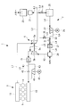
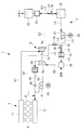
- FIG. 1 is a schematic configuration diagram showing the periphery of a diesel engine (internal combustion engine) according to an embodiment of the present invention. It is the graph which showed the EGR blower power with respect to the load of an engine main body. It is the schematic block diagram which showed the modification of FIG.
- FIG. 1 shows a schematic configuration around a diesel engine (internal combustion engine) 1 provided in a ship.
- the diesel engine 1 includes a diesel engine main body (hereinafter simply referred to as “engine main body”) 3 that is a main engine for marine propulsion, and a supercharger 5 that is driven by exhaust gas from the engine main body (internal combustion engine main body) 3.
- engine main body diesel engine main body
- supercharger 5 that is driven by exhaust gas from the engine main body (internal combustion engine main body) 3.
- EGR system 7 that performs low pressure EGR by recirculating a part of the exhaust gas guided from the supercharger 5 to the engine body 3.
- the engine body 3 is a marine two-cycle diesel engine, and for example, a uniflow type that is scavenged in one direction so as to supply air from below and exhaust upward is adopted.
- the output from the engine body 3 is directly or indirectly connected to the screw propeller via a propeller shaft (not shown).
- An exhaust port of a cylinder portion 9 (only four cylinders are shown as an example in FIG. 1) of each cylinder of the engine body 3 is connected to an exhaust static pressure tube 11 as an exhaust gas collecting tube.
- the exhaust static pressure pipe 11 is connected to the inlet side of the turbine 5a of the supercharger 5 via the first exhaust path L1.
- each cylinder section 9 is connected to the scavenging trunk 13, and the scavenging trunk 13 is connected to the compressor 5b of the supercharger 5 through the scavenging path K1.
- An air cooler 15 as an intercooler is installed in the scavenging path K1.
- the supercharger 5 includes a turbine 5a and a compressor 5b.
- the turbine 5a and the compressor 5b are coaxially connected by a rotating shaft 5c.
- the turbine 5a is driven by exhaust gas from the engine body 3, and the turbine work obtained by the turbine 5a is transmitted to the compressor 5b through the rotating shaft 5c.
- the compressor 5b sucks outside air (air) or a mixture of outside air and recirculation gas and raises the pressure to a predetermined scavenging pressure.
- the second exhaust path L2 is branched at a branch point 17 to the third exhaust path L3 or the EGR path L4.
- Distribution of the exhaust gas amount between the third exhaust path L3 and the EGR path L4 is performed by an EGR valve 19 provided on the upstream side of the EGR path L4.
- the opening degree of the EGR valve 19 is adjusted by a control unit (not shown).
- the EGR valve 19 is fully opened when the engine body 3 is operated at a rated load, and is fully closed when EGR is not performed.
- An economizer 21 and a scrubber 23 are sequentially connected to the third exhaust path L3.
- the economizer 21 generates steam by the exhaust gas from the engine body 3.
- the generated steam is used in various places on the ship.
- the scrubber 23 removes impurities such as SOx (sulfur oxide) and PM (particulate matter) contained in the exhaust gas by spraying a liquid such as water on the exhaust gas.
- the scrubber 23 is applied when a fuel containing a sulfur content of 0.1% or more is used as a fuel for the engine body 3, but a fuel containing a sulfur content of 0.1% or less is used. Can be omitted.
- An EGR scrubber 25 and an EGR blower 27 are sequentially connected to the downstream side of the EGR valve 19 provided in the EGR path L4.
- the EGR scrubber 25 removes impurities such as SOx and PM contained in the exhaust gas by spraying a liquid such as water on the exhaust gas flowing through the EGR path L4.
- the EGR blower 27 is rotationally driven by an electric motor 29 whose frequency is variable by an inverter.
- the EGR blower 27 is used so as to compensate for the pressure loss of the exhaust gas that occurs when the EGR valve 19 and the EGR scrubber 25 pass through the piping constituting the EGR path L4.
- the exhaust gas pressurized by the EGR blower 27 is guided to a first EGR bypass switching valve (EGR bypass switching means) 31 provided in the EGR path L4.
- a branch point 33 is provided between the EGR blower 27 and the first EGR bypass switching valve 31, and the EGR bypass path L ⁇ b> 5 is branched from the branch point 33.
- a second EGR bypass switching valve (EGR bypass switching means) 35 is provided in the EGR bypass path L5. The opening and closing of the first EGR bypass switching valve 31 and the second EGR bypass switching valve 35 are controlled by a control unit (not shown).
- the EGR path L4 or the EGR bypass path L5 is selected as the exhaust gas to be recirculated.
- a three-way valve may be provided.
- the EGR bypass path L5 is connected to the scavenging path K1 on the downstream side of the compressor 5b and on the upstream side of the air cooler 15. Thereby, the exhaust gas passing through the EGR bypass path L5 can bypass the compressor 5b.
- An EGR cooler 37 is provided on the EGR path L4 on the downstream side of the first EGR bypass switching valve 31. By the heat exchange with the cooling water led to the EGR cooler 37, the temperature of the recirculated exhaust gas is lowered to a desired value.
- a mixer 39 is provided on the downstream side of the EGR cooler 37. In the mixer 39, the recirculated exhaust gas and air are mixed. The mixed gas (only air when EGR is not performed) mixed in the mixer 39 is guided to the suction port of the compressor 5b through the air supply path K2.
- An auxiliary scavenging path K3 connected in parallel to the scavenging path K1 is provided on the downstream side of the compressor 5b.
- An auxiliary blower 41 is provided in the auxiliary scavenging path K3.
- the auxiliary blower 41 is driven by the electric motor 43, and is controlled so as to increase the pressure when the scavenging pressure pressurized by the compressor 5b at a low load does not rise to a desired value.
- the scavenging path K1 is provided with a check valve 45 so that the scavenging air pressurized by the auxiliary blower 41 does not flow back through the scavenging path K1.
- the operation of the diesel engine 1 having the above configuration will be described.
- EGR emission control area
- the EGR valve 19 is opened.
- a part of the exhaust gas guided from the engine body 3 to the turbine 5a through the first exhaust path L1 flows to the EGR system 7.
- the remaining exhaust gas is guided to the third exhaust path L3, and the economizer 21 and the scrubber 23 are emitted from a chimney (not shown) to the atmosphere.
- the exhaust gas flowing through the EGR system 7 flows through the EGR scrubber 25 through the EGR valve 19 as recirculation gas.
- the exhaust gas from which SOx and PM have been removed by the EGR scrubber 25 is guided to the EGR blower 27, and the exhaust gas pressurized to a predetermined pressure by the EGR blower 27 is guided to the branch point 33.
- the EGR path L4 or the EGR bypass path L5 is selected by the first EGR bypass switching valve 31 and the second EGR bypass switching valve 35.
- the load is switched by a preset switching load with respect to the load of the engine main body 3, and when the load of the engine main body 3 is larger than the switching load, the EGR path L4 is selected, and the load of the engine main body 3 is reduced.
- the EGR bypass path L5 is selected.
- the EGR bypass switching valve 31 is fully opened and the second EGR bypass switching valve 35 is fully closed.
- the EGR bypass path L5 is selected, the first EGR bypass switching valve 31 is fully closed and the second EGR bypass switching valve 35 is fully opened.
- the exhaust gas passes through the first EGR bypass switching valve 31 and is cooled by the EGR cooler 37 and then guided to the mixer 39. .
- the mixer 39 the air and the exhaust gas are mixed and guided to the intake port of the compressor 5b through the intake path K2.
- the mixture of air and exhaust gas pressurized by the compressor 5b is guided to the air cooler 15 through the scavenging path K1, cooled by the air cooler 15, and after passing through the check valve 45, the scavenging trunk 13 Led to.
- the exhaust gas passes through the second EGR bypass switching valve 35 and bypasses the compressor 5b, and downstream of the compressor 5b and an air cooler 15 to the upstream side.
- the bypassed exhaust gas and the air pressurized by the compressor 5b are mixed on the downstream side of the compressor 5b.
- the mixed gas of exhaust gas and air is guided to the scavenging trunk 13 after being cooled by the air cooler 15.
- the exhaust gas pressurized by the EGR blower 27 is guided to the scavenging trunk 13, and as a result, the pressure in the scavenging trunk 13 reaches a predetermined pressure,
- the auxiliary blower 41 can be stopped at a lower load than when it is not performed, and the operating power of the auxiliary blower 41 can be reduced.
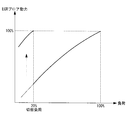
- FIG. 2 shows the EGR blower power with respect to the load of the engine body 3.
- the horizontal axis represents the load of the engine body 3 and the vertical axis represents the EGR blower power, both of which are indicated as 100% at the rated load.
- the power of the EGR blower 27 is consumed in proportion to the load of the engine body 3.
- the capacity of the EGR blower 27 is selected so that the EGR blower power is also 100% when the engine body 3 is at 100% load.
- the power of the EGR blower 27 is increased to 100%. This is because the compressor 5b is bypassed by selecting the EGR bypass path L5, so that the exhaust gas can be pressurized without being affected by the operating state of the supercharger 5.
- the power of the EGR blower 27 decreases in proportion to the scavenging pressure required by the engine main body 3.
- Exhaust gas guided by the EGR blower 27 through the EGR path L4 is passed through the EGR bypass path L5 to the scavenging trunk 13 by the first EGR bypass switching valve 31 and the second EGR bypass switching valve 35 which are EGR bypass switching means. I was able to guide. Accordingly, the exhaust gas can be directly guided to the scavenging trunk 13 by bypassing the compressor 5b, and contamination of the compressor 5b with the exhaust gas can be prevented. Further, when the EGR bypass path L5 is used, the exhaust gas is not guided to the compressor 5b, so that the composition of the fluid flowing into the compressor 5b is not changed by the exhaust gas (that is, only air is guided). Thus, stable operation of the supercharger 5 becomes possible.
- the exhaust gas amount of the engine body 3 is smaller than that at the rated load, and therefore the EGR gas amount is also smaller than that at the rated load. Therefore, there is a margin as the operating point of the EGR blower 27 compared to the rated load. Furthermore, since the scavenging pressure is also lower in the engine body 3 than at the rated load, it is possible to supply air by bypassing the compressor 5b using the EGR blower 27. Therefore, when the engine main body 3 is set to the switching load or less, the EGR bypass path L5 is selected to bypass the compressor 5b and directly guide the exhaust gas to the scavenging trunk 13. Thereby, the EGR blower 27 can be operated without being affected by the operation state of the compressor 5b, and can be easily controlled even at a low load.
- the energy for the electric drive is used for increasing the scavenging pressure. Thereby, the fuel consumption of the engine body 3 can be reduced.
- the exhaust gas leading to the scavenging trunk 13 is pressurized by the EGR blower 27.
- the auxiliary blower 41 can be stopped at a lower load than in the normal operation in which the operation is not performed, and the operation power of the auxiliary blower 41 can be reduced.
- downstream end of the EGR bypass path L5 may be the downstream side of the air cooler 15. Thereby, it is possible to avoid the exhaust gas from flowing through the air cooler 15 and reduce the risk of contamination of the air cooler 15.
- the marine diesel engine has been described as a premise.
- the present invention is not limited to this, and any internal combustion engine for automobiles or power generation can be applied.
Priority Applications (2)
| Application Number | Priority Date | Filing Date | Title |
|---|---|---|---|
| CN201380055294.1A CN104854338B (zh) | 2012-12-28 | 2013-12-27 | 内燃机、船舶及内燃机的运行方法 |
| KR1020157010227A KR101688752B1 (ko) | 2012-12-28 | 2013-12-27 | 내연기관 및 선박 및 내연기관의 운전방법 |
Applications Claiming Priority (2)
| Application Number | Priority Date | Filing Date | Title |
|---|---|---|---|
| JP2012288765A JP6309190B2 (ja) | 2012-12-28 | 2012-12-28 | 内燃機関および船舶ならびに内燃機関の運転方法 |
| JP2012-288765 | 2012-12-28 |
Publications (1)
| Publication Number | Publication Date |
|---|---|
| WO2014104329A1 true WO2014104329A1 (ja) | 2014-07-03 |
Family
ID=51021393
Family Applications (1)
| Application Number | Title | Priority Date | Filing Date |
|---|---|---|---|
| PCT/JP2013/085186 WO2014104329A1 (ja) | 2012-12-28 | 2013-12-27 | 内燃機関および船舶ならびに内燃機関の運転方法 |
Country Status (4)
| Country | Link |
|---|---|
| JP (1) | JP6309190B2 (zh) |
| KR (1) | KR101688752B1 (zh) |
| CN (1) | CN104854338B (zh) |
| WO (1) | WO2014104329A1 (zh) |
Cited By (1)
| Publication number | Priority date | Publication date | Assignee | Title |
|---|---|---|---|---|
| US10985608B2 (en) | 2016-12-13 | 2021-04-20 | General Electric Company | Back-up power system for a component and method of assembling same |
Families Citing this family (13)
| Publication number | Priority date | Publication date | Assignee | Title |
|---|---|---|---|---|
| KR102297863B1 (ko) * | 2014-09-23 | 2021-09-03 | 대우조선해양 주식회사 | 선박용 엔진의 배기가스 재순환 시스템 및 방법 |
| JP6171235B2 (ja) * | 2015-03-31 | 2017-08-02 | 三菱重工業株式会社 | Egrシステム |
| JP6109988B1 (ja) * | 2016-03-18 | 2017-04-05 | 三菱重工業株式会社 | Egrシステム |
| JP7129755B2 (ja) * | 2016-11-30 | 2022-09-02 | 三菱重工業株式会社 | 舶用ディーゼルエンジン |
| JP6841645B2 (ja) * | 2016-12-12 | 2021-03-10 | 三菱重工業株式会社 | Egrシステムおよびディーゼルエンジン |
| JP6789793B2 (ja) * | 2016-12-13 | 2020-11-25 | 三菱重工業株式会社 | 内燃機関 |
| DE102017115374A1 (de) * | 2017-07-10 | 2019-01-10 | Volkswagen Aktiengesellschaft | Abgasrückführungsanordnung eines Kraftfahrzeuges und Verfahren zum Betrieb einer Abgasrückführungsanordnung |
| JP7055705B2 (ja) * | 2018-06-12 | 2022-04-18 | 株式会社ジャパンエンジンコーポレーション | 舶用内燃機関 |
| JP7131983B2 (ja) * | 2018-06-25 | 2022-09-06 | 株式会社ジャパンエンジンコーポレーション | 舶用内燃機関 |
| JP7201345B2 (ja) * | 2018-06-25 | 2023-01-10 | 株式会社ジャパンエンジンコーポレーション | 舶用内燃機関 |
| CA3179023A1 (en) | 2019-04-08 | 2020-10-15 | Spi.Systems Corporation | Systems and methods for treated exhaust gas recirculation in internal combustion engines |
| GB2590942B (en) * | 2020-01-08 | 2022-08-31 | Perkins Engines Co Ltd | Air intake system for use in an internal combustion engine |
| JP2022045648A (ja) * | 2020-09-09 | 2022-03-22 | 株式会社ジャパンエンジンコーポレーション | 舶用内燃機関 |
Citations (3)
| Publication number | Priority date | Publication date | Assignee | Title |
|---|---|---|---|---|
| JPH06221228A (ja) * | 1993-01-28 | 1994-08-09 | Mazda Motor Corp | 過給機付エンジンの排気ガス還流装置 |
| JP2003535264A (ja) * | 2000-05-26 | 2003-11-25 | エンゲルハード・コーポレーシヨン | 過給ジーゼル機関のための低圧排気ガス再循環システム |
| JP2012127205A (ja) * | 2010-12-13 | 2012-07-05 | Mitsubishi Heavy Ind Ltd | 排ガス再循環システム |
Family Cites Families (12)
| Publication number | Priority date | Publication date | Assignee | Title |
|---|---|---|---|---|
| JPS5930905B2 (ja) * | 1978-05-12 | 1984-07-30 | 日野自動車株式会社 | 過給式ディ−ゼルエンジンのegr制御方法 |
| JPS63115567U (zh) * | 1987-01-21 | 1988-07-26 | ||
| JPH05256213A (ja) * | 1992-03-13 | 1993-10-05 | Mazda Motor Corp | 過給機付エンジンのegr装置 |
| JP2001227332A (ja) * | 2000-02-16 | 2001-08-24 | Mitsubishi Heavy Ind Ltd | 船舶の排ガス脱硝システム |
| JP2002285879A (ja) * | 2001-03-26 | 2002-10-03 | Isuzu Motors Ltd | 過給機付きエンジンの排ガス還流装置 |
| JP5444996B2 (ja) | 2009-09-25 | 2014-03-19 | いすゞ自動車株式会社 | 内燃機関及びその制御方法 |
| US8096125B2 (en) * | 2009-12-23 | 2012-01-17 | Ford Global Technologies, Llc | Methods and systems for emission system control |
| JP5787500B2 (ja) * | 2010-08-24 | 2015-09-30 | 三菱重工業株式会社 | エンジン排気ガス浄化装置及び船舶 |
| JP2012067609A (ja) * | 2010-09-21 | 2012-04-05 | Daihatsu Motor Co Ltd | ターボチャージャ付き内燃機関 |
| JP6041418B2 (ja) * | 2010-12-16 | 2016-12-07 | 臼井国際産業株式会社 | 重油以下の低質燃料を使用する大排気量船舶用ディーゼルエンジンの排気ガス浄化装置 |
| JP5377532B2 (ja) * | 2011-01-26 | 2013-12-25 | エムエーエヌ・ディーゼル・アンド・ターボ・フィリアル・アフ・エムエーエヌ・ディーゼル・アンド・ターボ・エスイー・ティスクランド | エネルギー回収構成を備える大型ターボ過給型ディーゼル機関 |
| DK177388B1 (en) * | 2011-01-31 | 2013-03-04 | Man Diesel & Turbo Deutschland | Large turbocharged two-stroke diesel engine with exhaust gas recirculation |
-
2012
- 2012-12-28 JP JP2012288765A patent/JP6309190B2/ja active Active
-
2013
- 2013-12-27 CN CN201380055294.1A patent/CN104854338B/zh not_active Expired - Fee Related
- 2013-12-27 KR KR1020157010227A patent/KR101688752B1/ko active IP Right Grant
- 2013-12-27 WO PCT/JP2013/085186 patent/WO2014104329A1/ja active Application Filing
Patent Citations (3)
| Publication number | Priority date | Publication date | Assignee | Title |
|---|---|---|---|---|
| JPH06221228A (ja) * | 1993-01-28 | 1994-08-09 | Mazda Motor Corp | 過給機付エンジンの排気ガス還流装置 |
| JP2003535264A (ja) * | 2000-05-26 | 2003-11-25 | エンゲルハード・コーポレーシヨン | 過給ジーゼル機関のための低圧排気ガス再循環システム |
| JP2012127205A (ja) * | 2010-12-13 | 2012-07-05 | Mitsubishi Heavy Ind Ltd | 排ガス再循環システム |
Cited By (1)
| Publication number | Priority date | Publication date | Assignee | Title |
|---|---|---|---|---|
| US10985608B2 (en) | 2016-12-13 | 2021-04-20 | General Electric Company | Back-up power system for a component and method of assembling same |
Also Published As
| Publication number | Publication date |
|---|---|
| KR101688752B1 (ko) | 2016-12-21 |
| CN104854338A (zh) | 2015-08-19 |
| KR20150055068A (ko) | 2015-05-20 |
| CN104854338B (zh) | 2018-08-03 |
| JP6309190B2 (ja) | 2018-04-11 |
| JP2014129790A (ja) | 2014-07-10 |
Similar Documents
| Publication | Publication Date | Title |
|---|---|---|
| WO2014104329A1 (ja) | 内燃機関および船舶ならびに内燃機関の運転方法 | |
| JP2014129790A5 (zh) | ||
| KR101886090B1 (ko) | 엔진 시스템 | |
| CN204253221U (zh) | 船舶柴油机NOx和SOx联合减排装置 | |
| CN107905920B (zh) | 一种基于进气成分控制降低增压柴油机排放的装置和方法 | |
| KR101607654B1 (ko) | 크로스헤드 및 배기가스 재순환 기능을 구비한 대형 저속 터보차지 2-행정 내연 기관 및 이의 작동 방법 | |
| CN102619615B (zh) | 带有排气再循环的大型涡轮增压二冲程柴油发动机 | |
| CN104358627A (zh) | 船舶柴油机NOx和SOx联合减排装置及控制方法 | |
| CN104405542A (zh) | 一种船舶二冲程柴油机废气再循环系统及控制方法 | |
| US8793997B2 (en) | Internal combustion engine | |
| JP2011038525A (ja) | 低圧egr/新気配合を利用したエンジン排気マニホルドの超大気圧過給のためのハイブリッド吸気系統 | |
| JP6122300B2 (ja) | エンジンシステム及び船舶 | |
| JP2010138892A (ja) | 直列に連結された2つの排気ターボチャージャを備える内燃機関 | |
| JP2012127205A (ja) | 排ガス再循環システム | |
| KR101685410B1 (ko) | 내연 기관 | |
| KR101683495B1 (ko) | 터보차저를 갖는 엔진 시스템 | |
| KR100982225B1 (ko) | 가습공기 디젤 엔진 | |
| JP2009191667A (ja) | 過給装置及び過給エンジンシステム | |
| US20220412053A1 (en) | Work vehicle power system with decoupled engine air system components | |
| KR20170128714A (ko) | 배기가스 재순환 시스템 | |
| CN105781809A (zh) | 一种船舶二冲程柴油机双涡轮egr系统及方法 | |
| CN204253220U (zh) | 一种船舶二冲程柴油机废气再循环系统 | |
| US20230365230A1 (en) | An air supply system for a hull of a vessel and a vessel comprising the air supply system | |
| CN110678634B (zh) | 内燃机的增压器剩余动力回收装置及船舶 | |
| JP2011174404A (ja) | 二段過給システム |
Legal Events
| Date | Code | Title | Description |
|---|---|---|---|
| 121 | Ep: the epo has been informed by wipo that ep was designated in this application |
Ref document number: 13868748 Country of ref document: EP Kind code of ref document: A1 |
|
| ENP | Entry into the national phase |
Ref document number: 20157010227 Country of ref document: KR Kind code of ref document: A |
|
| NENP | Non-entry into the national phase |
Ref country code: DE |
|
| 122 | Ep: pct application non-entry in european phase |
Ref document number: 13868748 Country of ref document: EP Kind code of ref document: A1 |