WO2014104247A1 - 炭酸水素ナトリウムの製造方法及び炭酸水素ナトリウムの製造装置 - Google Patents
炭酸水素ナトリウムの製造方法及び炭酸水素ナトリウムの製造装置 Download PDFInfo
- Publication number
- WO2014104247A1 WO2014104247A1 PCT/JP2013/084991 JP2013084991W WO2014104247A1 WO 2014104247 A1 WO2014104247 A1 WO 2014104247A1 JP 2013084991 W JP2013084991 W JP 2013084991W WO 2014104247 A1 WO2014104247 A1 WO 2014104247A1
- Authority
- WO
- WIPO (PCT)
- Prior art keywords
- nacl
- water
- containing water
- exchange resin
- amount
- Prior art date
- Legal status (The legal status is an assumption and is not a legal conclusion. Google has not performed a legal analysis and makes no representation as to the accuracy of the status listed.)
- Ceased
Links
Images

Classifications
-
- C—CHEMISTRY; METALLURGY
- C01—INORGANIC CHEMISTRY
- C01D—COMPOUNDS OF ALKALI METALS, i.e. LITHIUM, SODIUM, POTASSIUM, RUBIDIUM, CAESIUM, OR FRANCIUM
- C01D7/00—Carbonates of sodium, potassium or alkali metals in general
-
- C—CHEMISTRY; METALLURGY
- C02—TREATMENT OF WATER, WASTE WATER, SEWAGE, OR SLUDGE
- C02F—TREATMENT OF WATER, WASTE WATER, SEWAGE, OR SLUDGE
- C02F1/00—Treatment of water, waste water, or sewage
- C02F1/42—Treatment of water, waste water, or sewage by ion-exchange
-
- C—CHEMISTRY; METALLURGY
- C02—TREATMENT OF WATER, WASTE WATER, SEWAGE, OR SLUDGE
- C02F—TREATMENT OF WATER, WASTE WATER, SEWAGE, OR SLUDGE
- C02F1/00—Treatment of water, waste water, or sewage
- C02F1/42—Treatment of water, waste water, or sewage by ion-exchange
- C02F2001/422—Treatment of water, waste water, or sewage by ion-exchange using anionic exchangers
-
- C—CHEMISTRY; METALLURGY
- C02—TREATMENT OF WATER, WASTE WATER, SEWAGE, OR SLUDGE
- C02F—TREATMENT OF WATER, WASTE WATER, SEWAGE, OR SLUDGE
- C02F2103/00—Nature of the water, waste water, sewage or sludge to be treated
- C02F2103/10—Nature of the water, waste water, sewage or sludge to be treated from quarries or from mining activities
-
- C—CHEMISTRY; METALLURGY
- C02—TREATMENT OF WATER, WASTE WATER, SEWAGE, OR SLUDGE
- C02F—TREATMENT OF WATER, WASTE WATER, SEWAGE, OR SLUDGE
- C02F2209/00—Controlling or monitoring parameters in water treatment
- C02F2209/06—Controlling or monitoring parameters in water treatment pH
-
- C—CHEMISTRY; METALLURGY
- C02—TREATMENT OF WATER, WASTE WATER, SEWAGE, OR SLUDGE
- C02F—TREATMENT OF WATER, WASTE WATER, SEWAGE, OR SLUDGE
- C02F2209/00—Controlling or monitoring parameters in water treatment
- C02F2209/29—Chlorine compounds
-
- C—CHEMISTRY; METALLURGY
- C02—TREATMENT OF WATER, WASTE WATER, SEWAGE, OR SLUDGE
- C02F—TREATMENT OF WATER, WASTE WATER, SEWAGE, OR SLUDGE
- C02F2303/00—Specific treatment goals
- C02F2303/16—Regeneration of sorbents, filters
Definitions
- the present invention relates to a method and an apparatus for producing sodium hydrogen carbonate from NaCl-containing water.
- Patent Document 1 discloses a technique for recovering salt in water as valuable salt Na 2 CO 3 for water associated with resource mining. This is a method in which C 12 amine and CO 2 dissolved in an oil phase are reacted with NaCl to convert them to NaHCO 3 and then converted to Na 2 CO 3 by applying heat.
- Non-Patent Document 1 and Patent Document 2 disclose a method for producing NaHCO 3 from water containing NaCl using a weakly basic ion exchange resin, as represented by the formula (1).
- Patent Document 3 discloses a method using limestone (CaCO 3 ) as a CO 2 supply source. Further, in this method, CaCO 3 is burned to obtain CO 2 and, as represented by the formula (4), Ca (OH) 2 as a by-product is used as a regenerated alkali of the ion exchange resin.
- Patent Document 3 uses CO 2 gas generated during the production of Ca (OH) 2 as a reaction raw material and is fixed as a carbonate, and as a system that emits almost no CO 2 gas to the atmosphere, global warming This is an effective technique from the viewpoint of prevention. Moreover, since no oil is used, wastewater containing oil as a COD source is not generated. Furthermore, if the water flow conditions are appropriate, the reaction of formula (3) proceeds almost completely, so there is no loss of carbonate recovery and a very high recovery rate can be obtained.
- the water associated with resource mining which is the treated water, is subject to fluctuations in water quality and is not necessarily suitable for the ion exchange resin method.
- high-purity NaHCO 3 may not be stably recovered.
- the water associated with resource mining may be in a highly alkaline state with a pH of 9 or higher, that is, in a state where there are many OH 2 ⁇ ions.
- the regeneration reaction of the ion exchange resin proceeds together with the reaction of the above formula (3), and the hydrochloric acid adsorption reaction of the above formula (3) hardly occurs.
- Cl - ions flow out into the treated water, and the purity of NaHCO 3 obtained from the treated water becomes low.
- resource extraction associated water HCO 3 - in addition to NaCl, bicarbonate ions (HCO 3 -) or is carbonate material carbonate ion (CO 3 2-) and the like are included, resource extraction associated water HCO 3 -
- the ratio of ions, CO 3 2 ⁇ ions and Cl ⁇ ions is not necessarily constant.
- the reaction of the above formula (3) does not proceed easily due to equilibrium, and Cl ⁇ ions flow out into the treated water.
- the purity of NaHCO 3 obtained from the treated water is low.
- An object of the present invention is to provide a method and apparatus for manufacturing a sodium hydrogen carbonate which enables to recover high-purity NaHCO 3 from NaCl-containing water.
- the method for producing sodium bicarbonate of the present invention is a method for producing sodium bicarbonate comprising a recovery step of passing NaCl-containing water containing NaCl and a carbonate substance through an anion exchange resin and recovering NaHCO 3.
- a recovery step of passing NaCl-containing water containing NaCl and a carbonate substance through an anion exchange resin and recovering NaHCO 3.
- the pH adjustment of the NaCl-containing water is performed by adding CO 2 gas, hydrochloric acid, or air to the NaCl-containing water. Is preferred.
- the NaCl-containing water containing NaCl and a carbonate substance is preferably water associated with resource mining.
- the anion exchange resin may be an H 2 CO 3 type weakly basic ion exchange resin. preferable.
- the apparatus for producing sodium hydrogen carbonate according to the present invention is a recovery system in which a packed column filled with an anion exchange resin and NaCl-containing water containing NaCl and a carbonate substance are passed through the packed column to recover NaHCO 3. And, when passing the NaCl-containing water through the anion exchange resin, according to the ratio of the substance amount of Cl ⁇ ions to the substance amount of the total carbonate substance excluding free carbonic acid contained in the NaCl-containing water, PH adjusting means for adjusting the pH of the NaCl-containing water by adding a pH adjusting agent to the NaCl-containing water.
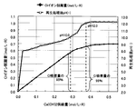
- FIG. 6 is a graph showing the relationship between the pH of a regeneration treatment solution and the amount of Cl-ion desorption with respect to the amount of Ca (OH) 2 supplied.
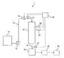
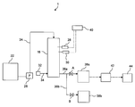
- FIG.1 and FIG.2 is a schematic block diagram which shows an example of a structure of the dissolved salt manufacturing apparatus which concerns on a reference example.
- the dissolved salt production apparatus 1 includes a drainage storage tank 10, a drainage inflow line 12, a drainage pump 14, a packed tower 16 filled with an anion exchange resin, a treated water discharge line 18, a treated water tank 20,
- the dissolved salt production apparatus 1 includes a Ca (OH) 2 storage tank 22, a Ca (OH) 2 inflow line 24, a Ca (OH) 2 pump 26, and a blower 32.
- the air inlet line 34, the regeneration processing liquid discharge lines 36a and 36b, and the regeneration processing liquid storage tanks 38a and 38b are further provided. As shown in FIG.
- the waste water inlet line 12 Cl - ion sensor 31 is installed.
- the treated water discharge line 18 Cl - ion sensor 21 is installed.
- the Cl ⁇ ion sensor 21 may be installed in the treated water tank 20.
- the packed tower 16, pH sensor 28, Cl - ions sensor 30 is installed.
- the Cl ⁇ ion sensors 21, 30, and 31 it is desirable to use sensors using Cl ⁇ ion electrodes.
- the dissolved salt manufacturing apparatus 1 is equipped with the control part 40, and is electrically connected with each sensor and the integrating
- the dissolved salt production apparatus 1 includes a concentrating device 42 and a drying device 44. It is desirable that a stirring device (not shown) is installed in the Ca (OH) 2 storage tank 22.
- a stirring device (not shown) is installed in the Ca (OH) 2 storage tank 22.
- the components shown in FIG. 1 when recovering NaHCO 3 described later, the components shown in FIG. 1 are installed in the packed tower 16, and when recovering CaCl 2 described later, The components shown in FIG. 1 may be removed and the components shown in FIG. 2 may be installed in the packed tower 16, or the components shown in FIGS. 1 and 2 may be supplied to the packed tower 16 through the recovery of NaHCO 3 and the recovery of CaCl 2 . May be installed.
- one end of the drainage inflow line 12 is connected to the drainage storage tank 10, and the other end is connected to the upper part of the packed tower 16.
- a drainage pump 14 and an integrating flow meter 19 are installed in the drainage inflow line 12.
- One end of the treated water discharge line 18 is connected to the bottom of the packed tower 16, and the other end is connected to the treated water tank 20.
- one end of the Ca (OH) 2 inflow line 24 is connected to the Ca (OH) 2 storage tank 22, and the other end is connected to the upper part of the packed tower 16.
- the Ca (OH) 2 inlet line 24 Ca (OH) 2 pump 26 is installed.
- One end of the air inflow line 34 is connected to the blower 32, and the other end is connected to the lower side surface of the packed tower 16.
- One end of the regeneration processing liquid discharge line 36a is connected to the lower side surface of the packed tower 16, the other end is connected to the regeneration processing liquid storage tank 38a, and one end of the regeneration processing liquid discharge line 36b is connected to the regeneration processing liquid discharge line 36a. The other end is connected to the regeneration processing liquid storage tank 38b.
- the drainage storage tank 10, the drainage inflow line 12, the drainage pump 14, the treated water discharge line 18, and the treated water tank 20 pass the resource mining associated water containing NaCl to the packed tower 16 and collect the NaHCO 3. It functions as a device.
- the first recovery device if a configuration of recovering NaHCO 3 from resource mining produced water containing NaCl, but is not limited to the above structure.
- the Ca (OH) 2 storage tank 22, the Ca (OH) 2 inflow line 24, and the Ca (OH) 2 pump 26 function as a regeneration device that regenerates the anion exchange resin in the packed tower 16.
- the regenerating apparatus is not limited to the above structure as long as it has a structure for regenerating an anion exchange resin.
- the second recovery device has a configuration for recovering the regeneration treatment solution until the pH of the regeneration treatment solution or the Cl ⁇ ion desorption amount of the anion exchange resin reaches a predetermined specified value,
- the present invention is not limited to this configuration.
- the concentrating device 42 has a function of concentrating the regeneration processing solution, and examples thereof include an evaporator and a liquid film lowering type concentrating device.
- the drying device 44 is for drying the concentrated reprocessing solution, and examples thereof include a dryer, an electric heating dryer, and a vacuum drum dryer.
- water associated with resource mining containing NaCl will be described as an example, but it is not particularly limited as long as it is NaCl-containing water containing NaCl, and is applied to industrial wastewater containing NaCl. Also good.
- the water associated with resource mining is water associated with resource mining such as natural gas such as CSG (Coal Seam Gas) or crude oil, and includes NaCl or the like.
- the pretreatment step is a step of removing suspended substances, oils, and the like contained in the water associated with resource mining by coagulation sedimentation, coagulation flotation separation, membrane filtration using an MF membrane / UF membrane, or the like.
- the concentration step is a step of concentrating water associated with resource mining with an RO membrane or the like to increase the NaCl concentration in the water.
- the concentration of NaCl in the concentrated resource extraction accompanying water is preferably 0.1 mol / L or more from the viewpoint of shortening the subsequent treatment time and performing efficient operation.
- Anion exchange resin is preferably H 2 CO 3 type weakly basic ion-exchange resin, and more preferably H 2 CO 3 type weakly basic acrylic ion exchange resin.
- H 2 CO 3 type weakly basic acrylic ion exchange resin will be described as an example.
- the H 2 CO 3 type weakly basic acrylic ion exchange resin is a carbonate-dissolved water obtained by dissolving carbonic acid in pure water or the like in a packed tower 16 filled with a weakly basic acrylic ion exchange resin before the first recovery step. It is necessary to pass water and convert it into H 2 CO 3 type.
- Examples of the dissolution of carbonic acid include a method of dissolving CO 2 gas in pure water or the like using a gas absorption tower or the like.
- As the CO 2 gas it is desirable to use CO 2 gas produced as a by-product when methane gas is burned or Ca (OH) 2 is produced from CaCO 3 .
- the resource extraction accompanying water containing NaCl in the drainage storage tank 10 passes through the drainage inflow line 12 by the drainage pump 14, and is a weak base of H 2 CO 3 type. Is supplied to a packed tower 16 filled with a functional acrylic ion exchange resin. Within packed tower 16 by H 2 CO 3 type weakly basic ion exchange resin, Cl - is adsorbed, it is treated water containing NaHCO 3 is discharged from the treated water discharge line 18, is stored in the treating tank 20. The treated water containing NaHCO 3 stored in the treated water tank 20 is then concentrated by a concentrating device 42 such as an evaporator and dried by a drying device 44 such as a dryer.
- a concentrating device 42 such as an evaporator
- a drying device 44 such as a dryer.
- Cl was placed in the treated water discharge line 18 - by the ion sensor 21, Cl in the treated water - monitoring the ion concentration, Cl - it is desirable that the ion concentration immediately terminated Once raised.
- the measurement data of the Cl ⁇ ion sensor 21 is sent to the control unit 40 and the control unit 40 electronically controls to stop the operation of the drainage pump 14 and the like when the Cl ⁇ ion concentration increases.
- H 2 CO 3 type weakly basic ion-exchange resins of Cl adsorbed - it is desirable to calculate the ion adsorption. Specifically, Cl was placed in the drainage inlet line 12 - and the ion concentration, Cl installed in the treated water discharge line 18 - - Cl of resource extraction associated water detected by the ion sensor 31 is detected by the sensor 21 treatment water Cl - is determined by multiplying the flow rate of the resource extraction produced water detected by the integrating flowmeter in the difference between the ion concentration (through water).
- Cl H 2 CO 3 type weakly basic ion exchange resin is adsorbed - ion adsorption amount, for example, the Cl - measurement data of the sensor and the integrated flow meter 19 is transmitted to the control unit 40 obtains by the control unit 40 It is done.
- the ion exchange resin used in the reference example is a weakly basic ion exchange resin having a tertiary amine type functional group.
- Amberlite IRA-67 is preferably used.
- the water passing SV of the resource extraction accompanying water in the first recovery step is preferably about 0.5 to 10 (1 / h).
- a Ca (OH) 2 solution (hereinafter sometimes referred to as Ca (OH) 2 slurry) is passed through the anion exchange resin to which HCl has been adsorbed in the first recovery step, and the above formula (4).
- a regeneration step is performed in which HCl is desorbed from the anion exchange resin to regenerate the anion exchange resin.
- Such a regeneration step is a batch type in which the Ca (OH) 2 slurry is gradually added to a predetermined condition while stirring the resin in the packed tower 16 and the reaction solution is discharged from the packed tower 16 after a certain time of reaction. You can go.
- the Ca (OH) 2 slurry may be passed through the packed tower 16 to continuously discharge the regeneration treatment liquid. From the viewpoint of more efficiently advancing the reaction of formula (4) on the anion exchange resin covered with the slurry, a batch of gradually adding the Ca (OH) 2 slurry to a predetermined amount while stirring the anion exchange resin. The formula is preferred.
- the concentration of the Ca (OH) 2 slurry is preferably 5 to 10% when used in a batch system and 0.05 to 0.5% when used in a continuous system.
- the fluid for supplying air to the packed column 16 and stirring the anion exchange resin in the packed column 16 is not limited to air, and any fluid that does not hinder the reaction of formula (4) may be used.
- any fluid that does not hinder the reaction of formula (4) may be used.
- methane gas etc. are mentioned.
- undissolved Ca (OH) 2 is Ca 2+ and OH - from the dissolved, OH - because cause regeneration reaction with HCl on an anion exchange resin, the added Ca (OH) 2 is reproduced In some cases, it takes a time of several minutes to 10 minutes to be fully used in the process. Therefore, it is preferable that the addition of the Ca (OH) 2 slurry in a batch system is performed intermittently in consideration of the time.
- the second recovery step for recovering the reclaimed processing liquid discharged from the packed tower 16 is performed.
- the pH of the regeneration treatment solution is monitored, and the recovered regeneration solution is concentrated and dried until the monitored pH value reaches a predetermined value.
- reproduction processing solution Cl - monitoring the ion concentration monitoring the Cl - Cl anion exchange resin obtained based on the ion concentration - ion elimination amount recovered to reach a predetermined default reproduction processing solution Is concentrated and dried.
- pH and Cl reproduction process liquid to the supply amount of Ca (OH) 2 - is a diagram showing the relationship between ion desorption amount.
- FIG. 3 when monitoring the pH of the regeneration treatment solution, before complete regeneration, the Ca (OH) 2 that has passed through the packed column 16 is consumed by the anion exchange resin, while the anion exchange resin. Since HCl is desorbed from the ion exchange resin, the pH of the regeneration treatment solution is lower than the pH 12.2 of the Ca (OH) 2 slurry (when the water temperature is 20 ° C.). The purity of CaCl 2 is high.
- the pH of the regeneration treatment liquid in the packed tower 16 is monitored by a pH sensor, and the monitored pH value is transmitted to the control unit 40. Then, for example, the control unit 40 compares the pH value of the regeneration processing solution with a predetermined pH value set in advance, and while the pH value does not reach the preset specified value, CaCl 2 in the regeneration processing solution. Therefore, the valve A provided in the regeneration processing liquid discharge line 36a is opened, and the valve B provided in the regeneration processing liquid discharge line 36b is closed. That is, while the pH value is less than the preset specified value, the regeneration processing liquid is supplied from the regeneration processing liquid discharge line 36a to the regeneration processing liquid storage tank 38a.
- the processing liquid stored in the regeneration processing liquid storage tank 38a is sent to a concentrating device 42 such as an evaporator and concentrated, and then sent to a drying device 44 such as a dryer and dried to recover high-purity CaCl 2. .
- a concentrating device 42 such as an evaporator and concentrated
- a drying device 44 such as a dryer and dried to recover high-purity CaCl 2.
- the valve A is closed and the valve B is opened because the purity of the CaCl 2 in the regenerating solution is lowered.
- the regeneration processing liquid is supplied from the regeneration processing discharge line 36b to the regeneration processing storage tank 38b.
- the comparison between the pH value and the specified value, the opening / closing of the valve, and the like may be performed by electronic control by the control unit 40 or may be performed manually by an operator.
- the pH value of the regeneration treatment liquid can be measured by the pH sensor 28 installed in the packed tower 16, but when it is a continuous type, the regeneration treatment liquid It is necessary to install a pH sensor in the discharge line 36a or the regeneration processing liquid storage tank 38a and measure the pH of the regeneration processing liquid.
- the specified value to be set in advance is not particularly limited as long as it is a value capable of recovering high-purity CaCl 2 , but in the case of pH monitoring, it should be set to the pH value of the Ca (OH) 2 slurry. Is preferable, and it is more preferable to set between pH 10.0 and 12.0.
- By setting the specified value to pH 12.0 or less it is possible to reliably transfer the regeneration treatment liquid containing high-purity CaCl 2 to the concentration / drying step.
- by setting the specified value to pH 10.0 or more it is possible to suppress an increase in the amount of the regeneration treatment liquid to be stored, and it is possible to use a storage facility having a small capacity.
- Cl reproduction process liquid discharged from the packed tower 16 - ion concentration, Cl - is monitored by the ion sensor, the monitored Cl - ion concentration value is transmitted to the control unit 40.
- the desorption amount of Cl 2 ⁇ ions adsorbed on the anion exchange resin can be obtained by the product of the Cl 2 ⁇ ion concentration of the regeneration treatment solution and the regeneration treatment solution amount.
- the control unit 40 If playback processing solution volume is constant, the control unit 40, the monitored Cl - obtained by multiplying the constant ion density values, if the flow rate of regeneration treatment solution is constant, the reproduction processing liquid discharge line 36a the integrating flowmeter was placed, and transmits the flow rate value of the measured playback processing solution by integrating flowmeter to the control unit 40, the control unit 40, the monitored Cl - flow rate of the measured playback processing solution ion concentration value It is obtained by multiplying the value. Then, the controller 40 compares, for example, the Cl ⁇ ion desorption amount adsorbed on the weakly basic ion exchange resin with a preset specified value, and the Cl ⁇ ion desorption amount becomes the preset specified value.
- the valve A is opened and the electromagnetic valve B is closed. That is, while the Cl 2 ⁇ ion desorption amount is less than a preset specified value, the regeneration processing liquid is supplied from the regeneration processing liquid discharge line 36a to the regeneration processing liquid storage tank 38a.
- the processing liquid stored in the regeneration processing liquid storage tank 38a is sent to a concentrating device 42 such as an evaporator and concentrated, and then sent to a drying device 44 such as a dryer and dried to recover high-purity CaCl 2. .
- the Cl ⁇ ion concentration of the regenerated solution can be measured by a Cl ⁇ ion sensor 30 installed in the packed tower 16. , Cl playback processing liquid discharge line 36a or reproducing processing liquid reservoir 38a - installing an ion sensor, Cl reproduction processing solution - it is necessary to measure the ion concentration.
- the specified value to be set in advance is not particularly limited as long as it is a value capable of recovering high-purity CaCl 2 , but in the case of Cl ⁇ ion concentration monitoring, the amount of Cl ⁇ ion adsorption of the anion exchange resin is not limited. preferably set to a value, Cl anion exchange resin - and more preferably set between 85 to 96% of the ion adsorption values.
- the specified value By setting the specified value to be 85% or more of the value of the Cl ⁇ ion adsorption amount of the anion exchange resin, it is possible to suppress an increase in the amount of the regenerated processing liquid to be stored, and to use a storage facility with a small capacity. It becomes possible.
- the calculation of the Cl ⁇ ion adsorption amount of the anion exchange resin is as described above.
- the Ca (OH) 2 slurry is further introduced into the packed column 16 to completely regenerate the anion exchange resin.
- Complete regeneration after regeneration treatment liquid i.e., reproduction processing liquid stored as reproduction processing liquid reservoir 38b playback processing liquid discharge line 36b as described above, Cl - somewhat containing ions, Cl - as compared with ion Since the content of Ca (OH) 2 is large, it is desirable to store it for use as a regenerant for regenerating the anion exchange resin in the next cycle. Further, when there are a plurality of packed columns 16 filled with an anion exchange resin, they may be used for regeneration of other series. By doing so, the number of storage facilities can be reduced.
- this washing waste water is a dilute slaked lime solution, it may be used as dissolved water for preparing a Ca (OH) 2 slurry.
- FIG. 4 is a schematic configuration diagram showing an example of the configuration of the sodium hydrogen carbonate production apparatus according to the present embodiment.
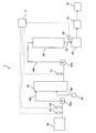
- the sodium hydrogen carbonate production apparatus 2 includes a drainage storage tank 46, drainage inflow lines 48a and 48b, drainage pumps 50a and 50b, a pH adjusting tower 52, a blower 54, a gas inflow line 56, and an anion exchange resin. Is provided with a packed tower 58, a treated water discharge line 60, and a treated water tank 62.
- the wastewater inflow line 48a Cl - ion sensor 64 and the alkalinity gauge 68 is installed, the waste water inlet line 48b is installed pH sensors 70, Cl is the treated water discharge line 60 - Ion A sensor 66 is installed.
- the Cl ⁇ ion sensor 66 may be installed in the treated water tank 62.
- the Cl - ion sensors 64 and 66 it is desirable to use sensors using Cl - ion electrodes. It is preferable to use an alkalinity meter that can measure both M alkalinity and P alkalinity.
- the sodium hydrogen carbonate production apparatus 2 includes a control unit 72 and is electrically connected to each sensor and the alkalinity meter 68, and the measured values of each sensor and the alkalinity meter 68 are transmitted. It has become so.
- the sodium hydrogen carbonate production apparatus 2 includes a concentrating device 74 and a drying device 76.
- one end of the drainage inflow line 48 a is connected to the drainage storage tank 46, and the other end is connected to the upper part of the pH adjustment tower 52.
- a drainage pump 50a is installed in the drainage inflow line 48a.
- One end of the gas inflow line 56 is connected to the blower 54, and the other end is connected to the side surface of the pH adjusting tower 52.
- One end of the drainage inflow line 48 b is connected to the lower side surface of the pH adjusting tower 52, and the other end is connected to the upper part of the packed tower 58.
- a drainage pump 50b is installed in the drainage inflow line 48b.
- One end of the treated water discharge line 60 is connected to the bottom of the packed tower 58, and the other end is connected to the treated water tank 62.
- the drainage inflow line 48b, the drainage pump 50b, the treated water discharge line 60, and the treated water tank 62 function as a recovery device that passes the water associated with resource mining containing NaCl to the packed tower 58 and recovers NaHCO 3. .
- the recovery device is not limited to the above-described configuration as long as it has a configuration for recovering NaHCO 3 from the water associated with resource mining containing NaCl.
- the drainage inflow line 48a, the drainage pump 50a, the pH adjusting tower 52, the blower 54, and the gas inflow line 56 function as a pH adjusting device that adjusts the pH of the water associated with resource mining.
- the pH adjusting device is not limited to the above configuration as long as it has a configuration for adjusting the pH of the resource mining accompanying water. It is preferable to fill the pH adjusting tower 52 with a filler such as Raschig ring from the viewpoint of shortening the pH adjustment time of the water associated with resource mining and suppressing the amount of the gas for adjusting the pH used.
- the concentrating device 74 has a function of concentrating the regeneration treatment liquid, and examples thereof include an evaporator and a liquid film descending evaporation concentrating device.
- the drying device 76 is for drying the concentrated regeneration treatment liquid, and examples thereof include an electric heating dryer and a vacuum drum dryer.
- the wastewater to be treated in this embodiment is described as an example of resource mining accompanying water containing NaCl and a carbonate substance, but is not particularly limited as long as it is NaCl-containing water containing NaCl and a carbonate substance. You may apply to the industrial waste water containing a carbonic acid substance.
- the water associated with resource mining is water associated with resource mining such as natural gas such as CSG (Coal Seam Gas) or crude oil, and includes NaCl or the like.
- the carbonate substance is bicarbonate ion (HCO 3 ⁇ ), carbonate ion (CO 3 2 ⁇ ), free carbonic acid (soluble CO 2 ) and the like.
- the pretreatment step is a step of removing suspended substances, oil, and the like contained in the water associated with resource mining by coagulation sedimentation, coagulation flotation separation, membrane filtration using an MF membrane / UF membrane, or the like.
- the concentration step is a step of concentrating water associated with resource mining with an RO membrane or the like to increase the NaCl concentration in the water.
- the concentration of NaCl in the concentrated resource extraction accompanying water is preferably 0.1 mol / L or more from the viewpoint of shortening the subsequent treatment time and performing efficient operation.
- the amount of Cl ⁇ ions relative to the amount (mole) of all carbonic substances (HCO 3 ⁇ , CO 3 2 ⁇ ) excluding free carbonic acid in the water associated with resource mining (after the pretreatment / concentration step) (The pH adjustment step of adjusting the pH of the water associated with resource mining is carried out according to the ratio (molar ratio) of (mol).
- the pH adjustment step of adjusting the pH of the water associated with resource mining is carried out according to the ratio (molar ratio) of (mol).
- the treated water discharged from the packed column 58 includes NaHCO 3 in addition to NaHCO 3 . Since Na 2 CO 3 is contained, there is no problem with the purity of the dissolved salts, but the purity of NaHCO 3 alone is lowered. Further, when the water associated with resource mining with a pH of 9.5 or more is passed through the packed tower 58 at the subsequent stage, the regeneration reaction of the ion exchange resin by OH ⁇ ions occurs simultaneously with the reaction of the above formula (3).
- the pH of the water associated with resource mining is set to 7.0 or more and 8.0 or less.
- most of the total carbonic acid contained in the water associated with resource mining is HCO 3 ⁇ , so that more NaHCO 3 with high purity can be obtained from the treated water discharged from the packed column 58 at the subsequent stage. It can be recovered.
- the pH of the water associated with resource mining is 6.5 to 8.5 It is adjusted to the range to become difficult to proceed the reaction of the above formula (3), Cl to treated water discharged from the packed tower 58 - incorporation of ions becomes large.
- the amount of HCO 3 ⁇ with respect to Cl ⁇ ions can be reduced by lowering the pH of the water associated with resource mining from the above range and converting the carbon dioxide in the resource mining accompanying water to free carbonic acid. The reaction of the above formula (3) is likely to proceed.
- the reaction of the above formula (3) can be promoted by the property of the anion exchange resin that performs ion exchange at a low pH. Therefore, Cl to treated water - mixing of ions is reduced, can be recovered NaHCO 3 in high purity from the treated water.
- the pH should be lowered, but as shown below, a reference value is set for the ratio of the amount of Cl ⁇ ions to the amount of all carbonates excluding free carbonic acid in the water associated with resource mining. It is preferable to adjust the pH.
- the pH adjustment tower 52 sets the pH of the resource extraction associated water to 6.5 to 8 is preferably adjusted to .5 or less, more preferably adjusted to 7.0 or more and 8.0 or less, relative to the amount of substance of all carbon materials except for free carbon dioxide of resource extraction associated water Cl - of the amount of substance of ions If the ratio is less than 2, the pH adjustment tower 52 preferably adjusts the pH of the water associated with resource mining to a range of 5.6 or more and less than 6.5.
- the pH adjustment tower 52 adjusts the pH of the water associated with resource mining to 6 It is preferable to adjust to a range of from 0.0 to less than 6.5, and if the ratio of the amount of Cl ⁇ ions to the amount of all carbonates excluding free carbonic acid in the water associated with resource mining is less than 1, pH adjustment It is preferable to adjust the pH of the water associated with resource mining to a range of 5.6 to less than 6.0 in the tower 52.
- the pH adjustment process will be described in detail with reference to FIG. 4.
- the resource mining accompanying water containing NaCl and carbonated material in the drainage storage tank 46 is sent to the drainage inflow line 48a by the drainage pump 50a.
- Cl of resource extraction associated water through the drainage inlet line 48a - substance amount of ions (mol) of Cl - is measured by the ion sensor 64, the alkalinity of the resource extraction associated water is measured by the alkalinity meter 68.
- Measured Cl - amount of substance and alkalinity ions are transmitted to the control unit 72.
- the pH of the resource extraction accompanying water discharged from the pH adjustment tower 52 is measured by the pH sensor 70 installed in the drainage inflow line 48 b, and the measured value is transmitted to the control unit 72. Further, the pH of the water associated with resource mining discharged from the pH adjusting tower 52 is Cl ⁇ ion with respect to the amount (mole) of the total carbonic substances (HCO 3 ⁇ , CO 3 2 ⁇ ) excluding free carbonic acid in the water associated with resource mining.
- the output of the blower 54 and the like is controlled by the control unit 72 so as to satisfy the pH range, and the CO 2 gas or air The supply amount is adjusted.
- CO 2 gas when lowering the pH of the water associated with resource mining, CO 2 gas is supplied (or added with HCl or the like described later), and when increasing the pH of the water associated with resource mining, air is supplied (or NaOH and the like to be described later are added).
- CO 2 gas be utilized the CO 2 by-product produced when burning hydrated lime Ca (OH) 2 or limestone CaCO 3 to be used for regeneration of the ion exchange resin described later
- CO 2 gas obtained by burning methane gas obtained locally it is also possible to use CO 2 gas obtained by burning methane gas obtained locally.
- Anion exchange resin is preferably H 2 CO 3 type weakly basic ion-exchange resin, and more preferably H 2 CO 3 type weakly basic acrylic ion exchange resin.
- H 2 CO 3 type weakly basic acrylic ion exchange resin will be described as an example.
- the H 2 CO 3 type weakly basic acrylic ion exchange resin is passed through a packed tower 58 filled with a weakly basic ion exchange resin before the recovery step, by passing carbonate-dissolved water in which carbonate is dissolved in pure water or the like. , Obtained by converting to H 2 CO 3 type.
- Examples of the dissolution of carbonic acid include a method of dissolving CO 2 gas in pure water or the like using a gas absorption tower or the like.
- the CO 2 gas it is desirable to use CO 2 gas produced as a by-product when methane gas is burned or Ca (OH) 2 is produced from CaCO 3 .
- the resource extraction accompanying water adjusted in pH and containing NaCl and carbonated material flowing through the drainage inflow line 48b is weakly basic of H 2 CO 3 type by the drainage pump 50b. It is supplied to a packed tower 58 filled with an ion exchange resin. Within packed tower 58 by H 2 CO 3 type weakly basic ion exchange resin, Cl - is adsorbed, it is treated water containing NaHCO 3 is discharged from the treated water discharge line 60, is stored in the treating tank 62. The treated water containing NaHCO 3 stored in the treated water tank 62 is then concentrated by a concentrating device 74 such as an evaporator and dried by a drying device 76 such as a dryer.
- a concentrating device 74 such as an evaporator
- a drying device 76 such as a dryer.
- Cl was placed in the treated water discharge line 60 or processed water tank 62 - by ion sensor 66, Cl in the treated water - monitoring the ion concentration, Cl - that the ion concentration is finished soon rises desirable.
- the measurement data of the Cl ⁇ ion sensor 66 may be sent to the control unit 72, and electronic control may be performed by the control unit 72 to stop the operation of the drainage pump 50b and the like when the Cl ⁇ ion concentration increases.
- the weakly basic ion exchange resin used in this embodiment is preferably a weakly basic acrylic ion exchange resin having an acrylic tertiary amine type functional group.
- a weakly basic acrylic ion exchange resin having an acrylic tertiary amine type functional group For example, Amberlite IRA-67 is used. Is preferred. It is preferable that the water SV associated with resource mining in the recovery process is about 0.5 to 10 (1 / h).
- the pH of the water associated with resource mining supplied to the packed tower 58 is adjusted in accordance with the ratio of the amount of Cl ⁇ ions to the amount of the total carbonaceous material excluding free carbonic acid in the water associated with resource mining. Therefore, Cl ⁇ is efficiently adsorbed by the weak basic ion exchange resin in the packed column 58, and it becomes possible to recover NaHCO 3 with high purity.
- FIG. 5 is a schematic configuration diagram illustrating another example of the configuration of the sodium hydrogen carbonate production apparatus according to the present embodiment.
- the sodium hydrogen carbonate production apparatus 3 shown in FIG. 5 the same reference numerals are given to the same components as those in the sodium hydrogen carbonate production apparatus 2 shown in FIG.
- the sodium hydrogen carbonate production apparatus 3 includes an HCl storage tank 78, an HCl addition line 80, an HCl pump 82, and a pH adjustment tank 84.
- a pH sensor 70 is installed in the pH adjustment tank 84.
- a stirring device (not shown) is installed in the pH adjustment tank 84.
- one end of the drainage inflow line 48 a is connected to the drainage storage tank 46, and the other end is connected to the pH adjustment tank 84.
- One end of the HCl addition line 80 is connected to the HCl storage tank 78, and the other end is connected to the pH adjustment tank 84.
- One end of the drainage inflow line 48 b is connected to the pH adjustment tank 84, and the other end is connected to the upper part of the packed tower 58.
- a drainage pump 50b is installed in the drainage inflow line 48b.
- One end of the treated water discharge line 60 is connected to the bottom of the packed tower 58, and the other end is connected to the treated water tank 62.
- the drainage inflow line 48a, the pH adjustment tank 84, the HCl storage tank 78, the HCl addition line 80, and the HCl pump 82 function as a pH adjustment device that adjusts the pH of the water associated with resource mining.
- the pH adjusting device is not limited to the above configuration as long as it has a configuration for adjusting the pH of the resource mining accompanying water.
- the pH sensor 70 installed in the pH adjustment tank 84 measures the pH of the water associated with resource mining and transmits the measured value to the control unit 72.
- the pH of the water associated with resource mining in the pH adjustment tank 84 is such that the amount of Cl ⁇ ion relative to the amount (mole) of the total carbonic substances (HCO 3 ⁇ , CO 3 2 ⁇ ) excluding free carbonic acid in the resource mining accompanying water (
- the output of the HCl pump 82 and the like are controlled by the controller 72 so as to satisfy the pH range, and the supply amount of HCl is adjusted.
- Resource mining associated water adjusted according to the ratio of the mass (mol) of Cl ⁇ ions to the mass (mol) of all carbonic substances (HCO 3 ⁇ , CO 3 2 ⁇ ) excluding free carbonic acid in the resource mining associated water
- the pH is as described above.
- HCl is used for pH adjustment.
- an acid agent such as carbonated water can also be used. It is.
- the acid agent such as HCl is used for lowering the pH of the water associated with resource mining, and it is necessary to use an alkaline agent such as NaOH when the pH of the water associated with resource mining is increased.
- the resource extraction accompanying water whose pH is adjusted in the pH adjusting tank 84 is supplied to the packed tower 58 filled with the H 2 CO 3 type weakly basic ion exchange resin by the drainage pump 50b.
- Cl - Within packed tower 58 by H 2 CO 3 type weakly basic ion exchange resin, Cl - is adsorbed, it is treated water containing NaHCO 3 is discharged from the treated water discharge line 60, is stored in the treating tank 62.
- the treated water containing NaHCO 3 stored in the treated water tank 62 is then concentrated by a concentrating device 74 such as an evaporator and dried by a drying device 76 such as a dryer.
- Cl was placed in the treated water discharge line 60 or processed water tank 62 - by ion sensor 66, Cl in the treated water - monitoring the ion concentration, Cl - that the ion concentration is finished soon rises desirable.
- the control unit 72 is electronically controlled to stop the operation of the drain pump 50b and the like.
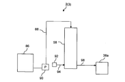
- FIG. 6 is a schematic configuration diagram showing an example of the configuration of the sodium hydrogen carbonate production apparatus when performing the regeneration process.
- the sodium hydrogen carbonate production apparatus (2, 3) includes a Ca (OH) 2 storage tank 86, a Ca (OH) 2 inflow line 88, a Ca (OH) 2 pump 90, a blower 92, and an air inflow.
- a line 94, a regeneration processing liquid discharge line 98, and a regeneration processing liquid storage tank 38a are provided.
- a stirring device (not shown) is installed in the Ca (OH) 2 storage tank 86.
- the components shown in FIG. 4 or 5 may be removed from the packed tower 58, and the components shown in FIG. 4 or 5 and the components shown in FIG. 6 may be installed in the packed tower 58 through the collection and regeneration process 3 .
- one end of the Ca (OH) 2 inflow line 88 is connected to the Ca (OH) 2 storage tank 86, and the other end is connected to the upper portion of the packed tower 58.
- the Ca (OH) 2 inlet line 88 Ca (OH) 2 pump 90 is installed.
- One end of the air inflow line 94 is connected to the blower 92, and the other end is connected to the lower side surface of the packed tower 58.
- One end of the regeneration processing liquid discharge line 98 is connected to the lower side surface of the packed tower 58, and the other end is connected to the regeneration processing liquid storage tank 38a.
- a Ca (OH) 2 solution (hereinafter sometimes referred to as Ca (OH) 2 slurry) is passed through the anion exchange resin to which HCl has been adsorbed in the recovery step, and the above formula (4).
- a regeneration step is performed in which HCl is desorbed from the weakly basic ion exchange resin to regenerate the weakly basic ion exchange resin.
- Ca (OH) operate the second pump 90
- Ca (OH) 2 Ca in the storage tank 86 (OH) 2 slurry Ca (OH) 2 inlet line 88 Is supplied to the packed tower 58 and the blower 92 is operated, and the air is supplied to the packed tower 58 through the air inflow line 94.
- HCl is desorbed from the anion exchange resin and CaCl 2 is generated by contacting the Ca (OH) 2 slurry with air while stirring the anion exchange resin.
- the regeneration processing liquid is supplied from the regeneration processing liquid discharge line 98 to the regeneration processing liquid storage tank 38a.
- the regeneration treatment liquid contains CaCl 2 , Ca (OH) 2, etc., and is sent to the concentrating device 74 and the drying device 76 as necessary.
- Such a regeneration step is a batch type in which the Ca (OH) 2 slurry is gradually added to a predetermined condition while stirring the resin in the packed column 58 and the reaction solution is discharged from the packed column 58 after a predetermined time of reaction. You can go.
- the Ca (OH) 2 slurry may be passed through the packed tower 58 to continuously discharge the regeneration treatment liquid. From the viewpoint of more efficiently advancing the reaction of formula (4) on the anion exchange resin covered with the slurry, a batch of gradually adding the Ca (OH) 2 slurry to a predetermined amount while stirring the anion exchange resin. The formula is preferred.
- the concentration of the Ca (OH) 2 slurry is preferably 5 to 10% when used in a batch system and 0.05 to 0.5% when used in a continuous system.
- the fluid for stirring the anion exchange resin in the packed tower 58 is not limited to air, and may be any fluid that does not inhibit the reaction of the formula (4), and examples thereof include methane gas.
- undissolved Ca (OH) 2 is Ca 2+ and OH - from the dissolved, OH - because cause regeneration reaction with HCl on an anion exchange resin, the added Ca (OH) 2 is reproduced In some cases, it takes a time of several minutes to 10 minutes to be fully used in the process. Therefore, it is preferable that the addition of the Ca (OH) 2 slurry in a batch system is performed intermittently in consideration of the time.
- CSG resources mining accompanying simulated water is subjected to coagulation pressure flotation separation for the purpose of SS removal and membrane filtration using a UF membrane as a pretreatment step, and further concentration using a reverse osmosis membrane (concentration by 10 times) Went.
- Table 1 summarizes the water quality of CSG resource mining accompanying simulated water (hereinafter referred to as treated water) after the pretreatment process and the concentration process.
- This treated water was concentrated under reduced pressure using an evaporator and evaporated to dryness using a hot plate (70 ° C.) to precipitate dissolved salts containing NaHCO 3 .
- a small amount of the precipitate was dissolved again in pure water, and the Cl - ion concentration was measured to confirm the Cl - ion content in the precipitate. It was confirmed that NaHCO 3 was recovered.
- the pH of the regenerating solution in the packed tower is 9.5 (Reference Example 1-1: 1st series), 10.0 (Reference Example 1-2: 2nd series), 10. 5 (Reference Example 1-3: third series), 11.7 (Reference Example 1-4: fourth series), 12.0 (Reference Example 1-5: fifth series), and 12.
- the regenerated waste liquid is taken out (hereinafter referred to as “first stage regenerated treatment liquid”), and concentrated under reduced pressure by an evaporator. And evaporation to dryness by a hot plate (70 ° C.) was performed to precipitate dissolved salts containing CaCl 2 .
- the regeneration treatment liquid after the additional addition of the Ca (OH) 2 slurry (hereinafter referred to as “second-stage regeneration treatment liquid”) is taken out, concentrated by distillation under reduced pressure using an evaporator, and Evaporation to dryness by a hot plate was performed to precipitate dissolved salts containing Ca (OH) 2 . A small amount of the precipitate was dissolved again in pure water, and the Ca 2+ and Cl ⁇ concentrations were measured to confirm the molar ratio of both elements in the precipitate. The results are summarized in Table 2.
- This Cl / Camol ratio of 1.86 has a CaCl 2 purity of 95.2% in terms of weight, and contains only 4.2% of Ca (OH) 2 as an impurity.
- the Cl / Camol ratio is 1.95 or higher.
- This Cl / Camol ratio when converted to weight, has a CaCl 2 purity of 98.3%, and contains only 1.7% of Ca (OH) 2 as an impurity. That is, the lower the pH of the first stage regeneration treatment solution or the lower the Cl desorption rate, the higher the purity of CaCl 2 recovered from the regeneration treatment solution. However, the lower the pH of the first stage regeneration treatment liquid or the lower the Cl desorption rate, the more the amount of the second stage regeneration treatment liquid tends to increase when the second stage regeneration treatment liquid is recovered. Therefore, it is predicted that the storage facility will become large.
- CaCl 2 can be obtained with high purity from water associated with resource mining containing NaCl.
- the pH of the regeneration treatment solution is measured, or the Cl ⁇ ion concentration is measured to determine the amount of Cl desorption, and the regeneration recovered until they reach a predetermined set value. It has been found that it is necessary to concentrate and dry the treatment liquid, that is, to obtain CaCl 2 from a regeneration treatment liquid having a relatively high CaCl 2 purity.
- the range of the set value is set between pH 10.0 and 12.0 in the case of pH measurement, and between 85 and 96% of the Cl ⁇ ion adsorption amount in the case of Cl ⁇ ion concentration measurement. It is preferable.
- Reference Example 2 CSG resource mining accompanying water was passed through a resin tower, NaHCO 3 was collected, and the same operation as in Reference Example 1 was performed until it was washed with pure water. Thereafter, the packed column, pH and Cl regeneration treatment solution - while measuring the ion concentration, the second stage regeneration treatment liquid obtained in Reference Example 1-4 (purity CaCl 2 is low) was intermittently added . After using all of the second stage regeneration solution, 5 w / v% Ca (OH) 2 slurry was added intermittently. Then, when the pH of the regeneration treatment solution reached 11.7, the regeneration treatment solution in the packed tower was taken out.
- the reclaimed reprocessing solution (first stage regenerating solution) was concentrated by vacuum distillation with an evaporator and evaporated to dryness with a hot plate to precipitate dissolved salts containing CaCl 2 . A small amount of the precipitate was dissolved again in pure water, and the Ca 2+ and Cl ⁇ concentrations were measured to confirm the molar ratio of both elements in the precipitate.
- Example 1 by blowing CO 2 gas into the simulated wastewater pH 9.5, adjusted simulated wastewater in pH 6.7 ⁇ 9, and not blown CO 2 gas for comparison, the simulated wastewater pH 9.5, weakly basic acrylic ion Water was passed through a packed tower packed with 200 mL of an exchange resin (Amberlite IRA-67, manufactured by Organo Corporation, exchange capacity 1.6 eq / LR).
- the weakly basic acrylic ion exchange resin in the packed tower is prepared by passing CO 2 dissolved water in advance to convert the entire amount of weakly basic ion exchange resin into H 2 CO 3 type, and then simulating the above.
- the drainage was passed at SV 1.0 (1 / h).
- Example 2 Example 1 except that air was blown into pH 6.0 simulated waste water and adjusted to pH 6.5 to 8.4, and for comparison, air was not blown and pH 6.0 simulated waste water was used. As well as. The results of Example 2 are summarized in Table 5.
- Example 3 by blowing CO 2 gas into the simulated wastewater pH9.5, adjusted simulated wastewater in pH 6.4 ⁇ 8.0, and not blown CO 2 gas for comparison, except for using simulated waste water pH9.5 The same procedure as in Example 1 was performed. The results of Example 3 are summarized in Table 6.
- Example 4 by blowing CO 2 gas into the simulated wastewater pH9.5, adjusted simulated wastewater in pH 6.1 ⁇ 8.0, and not blown CO 2 gas for comparison, except for using simulated waste water pH9.5 The same procedure as in Example 1 was performed. The results of Example 4 are summarized in Table 7.
- Example 5 by blowing CO 2 gas into the simulated wastewater pH9.5, adjusted simulated wastewater in pH 5.8 ⁇ 6.5, and not blown CO 2 gas for comparison, except for using simulated waste water pH9.5 The same procedure as in Example 1 was performed. The results of Example 5 are summarized in Table 8.
Landscapes
- Chemical & Material Sciences (AREA)
- Organic Chemistry (AREA)
- Engineering & Computer Science (AREA)
- Materials Engineering (AREA)
- Inorganic Chemistry (AREA)
- Life Sciences & Earth Sciences (AREA)
- Hydrology & Water Resources (AREA)
- Environmental & Geological Engineering (AREA)
- Water Supply & Treatment (AREA)
- Treatment Of Water By Ion Exchange (AREA)
Abstract
NaCl及び炭酸物質を含有するNaCl含有水を陰イオン交換樹脂充填塔58に通水し、NaHCO3を回収する回収工程を備え、前記NaCl含有水を陰イオン交換樹脂充填塔58に通水する際に、前記NaCl含有水に含まれる遊離炭酸を除いた全炭酸物質の物質量に対するCl-イオンの物質量の比に応じて、前記NaCl含有水のpHを調整する炭酸水ナトリウムの製造方法により、前記NaCl含有水から高純度のNaHCO3を回収することが可能となる。
Description
本発明は、NaCl含有水から炭酸水素ナトリウムを製造する方法及び製造する装置に関する。
CSG(Coal Seam Gas)のような天然ガスや原油などの資源採掘で発生する随伴水には、高濃度でNaClやNaHCO3が含まれているため、脱塩処理をして水系環境に放流する必要がある。従来、除去された多量の塩は蒸発乾燥され、廃棄物処分されていた。一方で、これら塩類を有価物として回収する試みもなされている。
例えば、特許文献1には、資源採掘随伴水を対象に水中の塩を有価塩であるNa2CO3として回収する技術が開示されている。これは、油相中に溶解したC12アミンとCO2をNaClに反応させNaHCO3に変換し、熱をかけてNa2CO3に転化する方法である。
非特許文献1及び特許文献2には、式(1)で表されるように、NaClを含む水から弱塩基性イオン交換樹脂を用いてNaHCO3を製造する方法が開示されている。
R3N+CO2+NaCl+H2O → R3N-HCl+NaHCO3 式(1)
R3N+CO2+NaCl+H2O → R3N-HCl+NaHCO3 式(1)
上記方法では反応効率を高めるため、式(2)で表されるように、イオン交換樹脂にCO2溶解水を吹き込んで、樹脂上に重炭酸または炭酸が捕捉された型であるR3N-H2CO3(炭酸型)に変換してから、式(3)で表されるように、NaClを含む被処理水を通水して、NaHCO3を製造する。
R3N+CO2+H2O → R3N-H2CO3 式(2)
R3N-H2CO3+NaCl → R3N-HCl+NaHCO3 式(3)
R3N+CO2+H2O → R3N-H2CO3 式(2)
R3N-H2CO3+NaCl → R3N-HCl+NaHCO3 式(3)
特許文献3には、CO2の供給源として石灰石(CaCO3)を用いる方法が開示されている。また、この方法では、CaCO3を燃やしてCO2を得ると共に、式(4)で表されるように、副生物であるCa(OH)2をイオン交換樹脂の再生アルカリとして用いている。
R3N-HCl+Ca(OH)2 → R3N+CaCl2+2H2O 式(4)
R3N-HCl+Ca(OH)2 → R3N+CaCl2+2H2O 式(4)
特許文献3の方法は、Ca(OH)2製造時に発生するCO2ガスを反応原料として用い、炭酸塩として固定化するものであり、CO2ガスをほとんど大気へ排出しないシステムとして、地球温暖化防止の観点から有効な技術である。また、油分を使用しないため、COD源となる油分を含んだ排水が発生することもない。さらに、通水条件が適切であれば、式(3)の反応がほぼ完全に進行するため、炭酸塩の回収ロスがなく、非常に高い回収率が得られる。
R.Kunin,Ion Exchange In Chemical Synthesis,Industrial&Engineering Chemistry,1964,56(1),p35-39
ところで、工業的に一定かつ純粋なNaCl溶解水を用いてNaHCO3を生成させる場合とは異なり、被処理水である資源採掘随伴水は、水質の変動等もあり、必ずしもイオン交換樹脂法に適当なものではなく、従来のイオン交換樹脂法で処理を行っても高純度のNaHCO3を安定的に回収できない場合がある。
例えば、資源採掘随伴水は、pH9またはそれ以上といったアルカリ性の強い状態、すなわちOH-イオンが多い状態となっている場合があるが、そのような強アルカリ性の資源採掘随伴水が、イオン交換樹脂に流入すると、上記式(3)の反応と共に、イオン交換樹脂の再生反応も進行し、上記式(3)の塩酸吸着反応が生じにくくなる。すると、処理水にCl-イオンが流出し、処理水から得られるNaHCO3の純度が低いものとなる。
また、資源採掘随伴水には、NaClの他に、重炭酸イオン(HCO3
-)または炭酸イオン(CO3
2-)等の炭酸物質が含まれているが、資源採掘随伴水中のHCO3
-イオン、CO3
2-イオンとCl-イオンの比率は必ずしも一定でない。そして、資源採掘随伴水中のHCO3
-イオン濃度が高く、相対的にNaCl濃度が低い場合等は特に、平衡により上記式(3)の反応が進行しにくく、処理水にCl-イオンが流出し、処理水から得られるNaHCO3の純度が低いものとなる。
そこで、本発明の目的は、NaCl含有水から高純度のNaHCO3を回収することを可能とする炭酸水素ナトリウムの製造方法及び製造装置を提供することである。
(1)本発明の炭酸水素ナトリウムの製造方法は、NaCl及び炭酸物質を含有するNaCl含有水を陰イオン交換樹脂に通水し、NaHCO3を回収する回収工程を備える炭酸水素ナトリウムの製造方法であって、前記NaCl含有水を陰イオン交換樹脂に通水する際に、前記NaCl含有水に含まれる遊離炭酸を除いた全炭酸物質の物質量に対するCl-イオンの物質量の比に応じて、前記NaCl含有水のpHを調整する。
(2)上記(1)記載の炭酸水素ナトリウムの製造方法において、前記NaCl含有水のpHを調整する前に前記比に関する基準値を設定し、前記NaCl含有水のpHを調整するときは、前記比が前記基準値より小さい場合に、前記比が前記基準値より大きい場合と比べて、前記NaCl含有水のpHが低くなるようにすることが好ましい。
(3)上記(1)記載の炭酸水素ナトリウムの製造方法において、前記NaCl含有水に含まれる遊離炭酸を除いた全炭酸物質の物質量に対するCl-イオンの物質量の比が2以上の場合は、前記NaCl含有水のpHを6.5以上~8.5以下に調整し、前記NaCl含有水に含まれる遊離炭酸を除いた全炭酸物質の物質量に対するCl-イオン物質量の比が2未満の場合は、前記NaCl含有水のpHを5.6以上~6.5未満に調整することが好ましい。
(4)上記(1)または(2)記載の炭酸水素ナトリウムの製造方法において、前記NaCl含有水のpH調整は、前記NaCl含有水にCO2ガス、塩酸、又は空気を添加することにより行うことが好ましい。
(5)上記(1)~(4)のいずれか1つに記載の炭酸水素ナトリウムの製造方法において、NaCl及び炭酸物質を含有するNaCl含有水は、資源採掘随伴水であることが好ましい。
(6)上記(1)~(5)のいずれか1つに記載の炭酸水素ナトリウムの製造方法において、前記陰イオン交換樹脂は、H2CO3型の弱塩基性イオン交換樹脂であることが好ましい。
(7)本発明の炭酸水素ナトリウムの製造装置は、陰イオン交換樹脂を充填した充填塔と、NaCl及び炭酸物質を含有するNaCl含有水を前記充填塔に通水し、NaHCO3を回収する回収手段と、前記NaCl含有水を陰イオン交換樹脂に通水する際に、前記NaCl含有水に含まれる遊離炭酸を除いた全炭酸物質の物質量に対するCl-イオンの物質量の比に応じて、前記NaCl含有水にpH調整剤を添加して、前記NaCl含有水のpHを調整するpH調整手段と、を備える。
本発明によれば、NaCl含有水から高純度のNaHCO3を回収することを可能とする炭酸水素ナトリウムの製造方法及び製造装置を提供することができる。
以下、本発明の実施の形態について説明する。なお、本実施形態は本発明を実施する一例であって、本発明は本実施形態に限定されるものではない。
図1及び図2は、参考例に係る溶解塩類製造装置の構成の一例を示す概略構成図である。図1に示すように、溶解塩類製造装置1は、排水貯留槽10、排水流入ライン12、排水ポンプ14、陰イオン交換樹脂が充填された充填塔16、処理水排出ライン18、処理水槽20、積算流量計19、を備え、図2に示すように、溶解塩類製造装置1は、Ca(OH)2貯留槽22、Ca(OH)2流入ライン24、Ca(OH)2ポンプ26、ブロワ32、空気流入ライン34、再生処理液排出ライン36a,36b、再生処理液貯留槽38a,38bとをさらに備えるものである。図1に示すように、排水流入ライン12にはCl-イオンセンサ31が設置されている。処理水排出ライン18にはCl-イオンセンサ21が設置されている。Cl-イオンセンサ21は処理水槽20内に設置されていてもよい。図1及び2に示すように、充填塔16には、pHセンサ28、Cl-イオンセンサ30が設置されている。Cl-イオンセンサ21,30,31としては、Cl-イオン電極を用いたセンサを使用することが望ましい。また、図1及び図2に示すように、溶解塩類製造装置1は、制御部40を備え、各センサ及び積算流量計19と電気的に接続され、各センサ及び積算流量計19の測定値が送信されるようになっている。また、溶解塩類製造装置1は濃縮装置42及び乾燥装置44を備えている。なお、Ca(OH)2貯留槽22内には攪拌装置(不図示)が設置されていることが望ましい。参考例の溶解塩類製造装置1では、後述するNaHCO3を回収する際には、充填塔16に図1に示す構成部品を設置し、後述するCaCl2を回収する際には、充填塔16から図1に示す構成部品を取り外し、充填塔16に図2に示す構成部品を設置してもよいし、NaHCO3の回収及びCaCl2の回収を通して、充填塔16に図1及び2に示す構成部品を設置していてもよい。
図1に示すように、排水流入ライン12の一端は排水貯留槽10に接続され、他端は充填塔16の上部に接続されている。排水流入ライン12には、排水ポンプ14、積算流量計19が設置されている。処理水排出ライン18の一端は、充填塔16の底部に接続され、他端は処理水槽20に接続されている。また、図2に示すように、Ca(OH)2流入ライン24の一端はCa(OH)2貯留槽22に接続され、他端は充填塔16の上部に接続されている。Ca(OH)2流入ライン24にはCa(OH)2ポンプ26が設置されている。空気流入ライン34の一端は、ブロワ32に接続され、他端は充填塔16の下部側面に接続されている。再生処理液排出ライン36aの一端は充填塔16の下部側面に接続され、他端は再生処理液貯留槽38aに接続され、再生処理液排出ライン36bの一端は再生処理液排出ライン36aに接続され、他端は再生処理液貯留槽38bに接続されている。
排水貯留槽10、排水流入ライン12、排水ポンプ14、処理水排出ライン18及び処理水槽20は、NaClを含有する資源採掘随伴水を充填塔16に通水し、NaHCO3を回収する第1回収装置として機能するものである。但し、第1回収装置は、NaClを含有する資源採掘随伴水からNaHCO3を回収する構成を備えていれば、上記の構成に制限されるものではない。
Ca(OH)2貯留槽22、Ca(OH)2流入ライン24及びCa(OH)2ポンプ26は、充填塔16内の陰イオン交換樹脂を再生処理する再生装置として機能するものである。但し、再生装置は、陰イオン交換樹脂を再生処理する構成を備えていれば、上記の構成に制限されるものではない。
再生処理液排出ライン36a、再生処理液貯留槽38aは、後述するように、再生処理液のpH、又は再生処理液のCl-イオン濃度に基づいて求められる陰イオン交換樹脂のCl-イオン脱離量が予め定めた規定値に達するまでの再生処理液を回収する第2回収装置として機能するものである。但し、第2回収装置は、再生処理液のpH、又は陰イオン交換樹脂のCl-イオン脱離量が予め定めた規定値に達するまでの再生処理液を回収する構成を備えていれば、上記の構成に制限されるものではない。
濃縮装置42は、再生処理液を濃縮する機能を有するものであり、例えば、エバポレータ、液膜降下式濃縮装置等が挙げられる。また、乾燥装置44は、濃縮した再生処理液を乾燥させるものであり、例えば、ドライヤー、電熱加熱型ドライヤーや真空式ドラムドライヤー等が挙げられる。
以下、参考例の溶解塩類製造装置1の動作について説明する。
参考例の処理対象となる排水として、NaClを含む資源採掘随伴水を例に説明するが、NaClを含むNaCl含有水であれば特に制限されるものではなく、NaClを含む産業排水に適用してもよい。資源採掘随伴水とは、例えば、CSG(Coal Seam Gas)のような天然ガスや原油などの資源採掘で発生する随伴水であり、NaCl等を含むものである。
まず、NaClを含む資源採掘随伴水は、排水貯留槽10に供給される前に、前処理工程、濃縮工程を行うことが望ましい。前処理工程は、凝集沈殿、凝集浮上分離やMF膜・UF膜などを用いた膜ろ過等により、資源採掘随伴水に含まれる懸濁物質や油分等を除去する工程である。濃縮工程は、RO膜等により資源採掘随伴水を濃縮し、水中のNaCl濃度を高める工程である。濃縮された資源採掘随伴水中のNaCl濃度は、その後の処理時間を短くし効率的な運転を行う観点等から、0.1mol/L以上であることが望ましい。
<NaHCO3を回収する第1回収工程>
本参考例では、NaClを含む資源採掘随伴水を陰イオン交換樹脂に通水し、上記式(3)の反応でNaClをNaHCO3に交換し、NaHCO3を回収する第1回収工程を実施する。陰イオン交換樹脂は、H2CO3型の弱塩基性イオン交換樹脂であることが好ましく、H2CO3型の弱塩基性アクリル系イオン交換樹脂であることがより好ましい。以下、H2CO3型の弱塩基性アクリル系イオン交換樹脂を例として説明する。H2CO3型の弱塩基性アクリル系イオン交換樹脂は、第1回収工程前に、弱塩基性アクリル系イオン交換樹脂を充填した充填塔16に、純水等に炭酸を溶解した炭酸溶解水を通水し、H2CO3型に変換しておく必要がある。炭酸の溶解については、ガス吸収塔などを用いて、純水等にCO2ガスを溶解させる方法等が挙げられる。CO2ガスは、メタンガスの燃焼や、CaCO3からCa(OH)2を製造する際に副生したCO2ガスを使用することが望ましい。
本参考例では、NaClを含む資源採掘随伴水を陰イオン交換樹脂に通水し、上記式(3)の反応でNaClをNaHCO3に交換し、NaHCO3を回収する第1回収工程を実施する。陰イオン交換樹脂は、H2CO3型の弱塩基性イオン交換樹脂であることが好ましく、H2CO3型の弱塩基性アクリル系イオン交換樹脂であることがより好ましい。以下、H2CO3型の弱塩基性アクリル系イオン交換樹脂を例として説明する。H2CO3型の弱塩基性アクリル系イオン交換樹脂は、第1回収工程前に、弱塩基性アクリル系イオン交換樹脂を充填した充填塔16に、純水等に炭酸を溶解した炭酸溶解水を通水し、H2CO3型に変換しておく必要がある。炭酸の溶解については、ガス吸収塔などを用いて、純水等にCO2ガスを溶解させる方法等が挙げられる。CO2ガスは、メタンガスの燃焼や、CaCO3からCa(OH)2を製造する際に副生したCO2ガスを使用することが望ましい。
図1を用いて第1回収工程を具体的に説明すると、排水貯留槽10内のNaClを含む資源採掘随伴水が、排水ポンプ14により排水流入ライン12を通り、H2CO3型の弱塩基性アクリル系イオン交換樹脂を充填した充填塔16に供給される。充填塔16内では、H2CO3型の弱塩基性イオン交換樹脂により、Cl-が吸着され、処理水排出ライン18からNaHCO3を含む処理水が排出され、処理水槽20に貯留される。処理水槽20に貯留されたNaHCO3を含む処理水は、その後、エバポレータ等による濃縮装置42により濃縮され、ドライヤー等の乾燥装置44により乾燥処理される。本参考例における第1回収工程では、処理水排出ライン18に設置したCl-イオンセンサ21により、処理水中のCl-イオン濃度をモニタリングし、Cl-イオン濃度が上昇したら直ちに終了することが望ましい。例えば、Cl-イオンセンサ21の測定データが制御部40に送られ、Cl-イオン濃度が上昇した段階で、制御部40により、排水ポンプ14等の稼働を停止するように電子制御されていてもよいし、作業者がCl-イオンセンサ21の測定データをチェックして、Cl-イオン濃度が上昇した段階で、手動で排水ポンプ14等の稼働を停止してもよい。
また、参考例では、第1回収工程の開始から終了までに、H2CO3型の弱塩基性イオン交換樹脂が吸着したCl-イオン吸着量を算出しておくことが望ましい。具体的には、排水流入ライン12に設置したCl-イオンセンサ31により検出される資源採掘随伴水のCl-イオン濃度と、処理水排出ライン18に設置されたCl-センサ21により検出される処理水のCl-イオン濃度との差に積算流量計により検出した資源採掘随伴水の流量(通水量)を乗じることにより求められる。H2CO3型の弱塩基性イオン交換樹脂が吸着したCl-イオン吸着量は、例えば、各Cl-センサ及び積算流量計19の測定データが、制御部40に送信され、制御部40により求められる。
参考例において使用するイオン交換樹脂は第三アミン形の官能基を持った弱塩基性イオン交換樹脂であり、例えば、アンバーライトIRA-67を使用するのが好適である。第1回収工程における資源採掘随伴水の通水SVは、0.5~10(1/h)程度とすることが好適である。
<再生工程>
参考例では、第1回収工程においてHClが吸着した陰イオン交換樹脂にCa(OH)2溶液(以下、Ca(OH)2スラリーと呼ぶ場合がある)を通水して、上記式(4)の反応で、陰イオン交換樹脂からHClを脱離させ、陰イオン交換樹脂を再生する再生工程を実施する。なお、再生工程前には、充填塔16に純水を通水し、陰イオン交換樹脂間の間隙に滞留している資源採掘随伴水を洗い流すことが望ましい。
参考例では、第1回収工程においてHClが吸着した陰イオン交換樹脂にCa(OH)2溶液(以下、Ca(OH)2スラリーと呼ぶ場合がある)を通水して、上記式(4)の反応で、陰イオン交換樹脂からHClを脱離させ、陰イオン交換樹脂を再生する再生工程を実施する。なお、再生工程前には、充填塔16に純水を通水し、陰イオン交換樹脂間の間隙に滞留している資源採掘随伴水を洗い流すことが望ましい。
図2を用いて再生工程を具体的に説明すると、Ca(OH)2ポンプ26を稼働させ、Ca(OH)2貯留槽22内のCa(OH)2スラリーがCa(OH)2流入ライン24から充填塔16に供給されると共に、ブロワ32を稼働させ、空気が空気流入ライン34を通り、充填塔16に供給される。充填塔16内では、空気により、陰イオン交換樹脂が攪拌されながらCa(OH)2スラリーと接触することにより、陰イオン交換樹脂からHClが脱離され、有価物であるCaCl2が生成される。このような再生工程は、充填塔16内の樹脂を攪拌しながらCa(OH)2スラリーを所定条件まで徐々に添加し、一定時間反応後、再生処理液を充填塔16から排出させる回分式で行っても良い。また、Ca(OH)2スラリーを充填塔16に通水し再生処理液を連続的に排出させる連続式で行っても良い。スラリーに覆われた陰イオン交換樹脂上で式(4)の反応をより効率的に進める観点等から、陰イオン交換樹脂を攪拌しながらCa(OH)2スラリーを所定量まで徐々に添加する回分式のほうが望ましい。
Ca(OH)2スラリーの濃度は、回分式で使用する場合は5~10%が好適であり、連続式で使用する場合は、0.05~0.5%が好適である。
充填塔16に空気を供給して、充填塔16内の陰イオン交換樹脂を攪拌するための流体は、空気に限定されるものではなく、式(4)の反応を阻害しない流体であればよく、例えばメタンガス等が挙げられる。
再生工程では、未溶解のCa(OH)2がCa2+とOH-に溶解してから、OH-が陰イオン交換樹脂上のHClと再生反応を起こすので、添加したCa(OH)2が再生に十分に使われるのに数分~10分程度の時間を要する場合があるため、回分式でのCa(OH)2スラリーの添加はその時間を見込んで間欠的に行うことが好ましい。
<第2回収工程>
参考例では、充填塔16から排出される再生処理液を回収する第2回収工程を実施する。この際、再生処理液のpHをモニタリングし、モニタリングしたpH値が予め定めた既定値に達するまでに回収した再生処理液を濃縮及び乾燥する。又は再生処理液のCl-イオン濃度をモニタリングし、モニタリングしたCl-イオン濃度に基づいて求められる陰イオン交換樹脂のCl-イオン脱離量が予め定めた既定値に達するまでに回収した再生処理液を濃縮及び乾燥する。
参考例では、充填塔16から排出される再生処理液を回収する第2回収工程を実施する。この際、再生処理液のpHをモニタリングし、モニタリングしたpH値が予め定めた既定値に達するまでに回収した再生処理液を濃縮及び乾燥する。又は再生処理液のCl-イオン濃度をモニタリングし、モニタリングしたCl-イオン濃度に基づいて求められる陰イオン交換樹脂のCl-イオン脱離量が予め定めた既定値に達するまでに回収した再生処理液を濃縮及び乾燥する。
図3は、Ca(OH)2の供給量に対する再生処理液のpH及びCl-イオン脱離量との関係を示す図である。図3に示すように、再生処理液のpHをモニタリングする場合、完全再生前であれば、充填塔16に通水したCa(OH)2は、陰イオン交換樹脂により消費され、その一方で陰イオン交換樹脂からHClが脱離していく段階であるので、再生処理液のpHは、Ca(OH)2スラリーのpH12.2(水温20℃の場合)よりも低いpHであり、再生処理液中のCaCl2の純度は高い状態である。一方、完全再生後であれば、HClの脱離が終了し、充填塔16に通水したCa(OH)2スラリーが充填塔16から再生処理液として排出される段階であるので、再生処理液のpHは、Ca(OH)2スラリーのpH12.2(水温20℃の場合)に達し、再生処理液中のCaCl2の純度が低下していく状態である。
そこで、参考例では、充填塔16の再生処理液のpHが、pHセンサによりモニタリングされ、モニタリングされたpH値が制御部40に送信される。そして、制御部40により、例えば、再生処理液のpH値と予め設定した規定のpH値とが比較され、pH値が予め設定した規定値に達していない間は、再生処理液中のCaCl2の純度が高いため、再生処理液排出ライン36aに設けられたバルブAを開放し、再生処理液排出ライン36bに設けられたバルブBを閉じる。すなわち、pH値が予め設定した規定値未満の間は、再生処理液は、再生処理液排出ライン36aから再生処理液貯留槽38aに供給される。再生処理液貯留槽38aに貯留された処理液は、エバポレータ等の濃縮装置42に送られて濃縮された後、ドライヤー等の乾燥装置44に送られて乾燥され、高純度CaCl2が回収される。また、制御部40により、pH値が予め設定した規定値に達した場合には、再生処理液中のCaCl2の純度が低下していく段階に入るため、バルブAを閉じ、バルブBを開放する。すなわち、pH値が予め設定した規定値に達した後は、再生処理液は、再生処理排出ライン36bから再生処理貯留槽38bに供給される。なお、参考例では、pH値と規定値の比較及びバルブの開閉等を制御部40による電子制御により実施しても良いし、作業者による手動により実施してもよい。なお、充填塔16を回分式とした場合には、充填塔16内に設置したpHセンサ28により再生処理液のpH値を測定することができるが、連続式とした場合には、再生処理液排出ライン36a又は再生処理液貯留槽38aにpHセンサを設置し、再生処理液のpHを測定する必要がある。
予め設定する規定値としては、高純度のCaCl2を回収することができる値であれば特に制限されるものではないが、pHモニタリングの場合、Ca(OH)2スラリーのpH値に設定することが好ましく、pH10.0~12.0の間で設定することがより好ましい。規定値をpH12.0以下とすることにより、確実に高純度のCaCl2を含有する再生処理液を濃縮・乾燥工程に移行することが可能となる。また、規定値をpH10.0以上とすることにより、貯留する再生処理液が多くなることを抑制することができ、容量の小さな貯留設備を使用することが可能となる。
また、図2に示すように、再生処理液のCl-イオン濃度をモニタリングする場合、完全再生前であれば、陰イオン交換樹脂に吸着していたHClが脱離していく段階であるので、再生処理液中のCl-イオン濃度に基づいて求められる陰イオン交換樹脂のCl-イオン脱離量は、陰イオン交換樹脂のCl-イオン吸着量より低く、再生処理液中のCaCl2の純度は高い状態である。一方、完全再生後であれば、HClの脱離が終了し、充填塔16に通水したCa(OH)2スラリーが充填塔16から再生処理液として排出される段階であるので、陰イオン交換樹脂のCl-イオン脱離量は、陰イオン交換樹脂のCl-イオン吸着量に達し、再生処理液中のCaCl2の純度が低下していく状態である。
そこで、他の参考例では、充填塔16から排出される再生処理液のCl-イオン濃度が、Cl-イオンセンサによりモニタリングされ、モニタリングされたCl-イオン濃度値が制御部40に送信される。ここで、陰イオン交換樹脂に吸着していたCl-イオンの脱離量は、再生処理液のCl-イオン濃度と再生処理液量との積により求められる。再生処理液量が一定であれば、制御部40で、モニタリングされたCl-イオン濃度値に定数を乗じることにより求められ、再生処理液の流量が一定でなければ、再生処理液排出ライン36aに積算流量計を設置し、積算流量計により測定された再生処理液の流量値を制御部40に送信し、制御部40で、モニタリングされたCl-イオン濃度値に測定された再生処理液の流量値を乗じることにより求められる。そして、制御部40により、例えば、弱塩基性イオン交換樹脂に吸着していたCl-イオン脱離量と予め設定した規定値とが比較され、Cl-イオン脱離量が予め設定した規定値に達していない間は、再生処理液中のCaCl2の純度が高いため、バルブAを開放し、電磁バルブBを閉じる。すなわち、Cl-イオン脱離量が予め設定した規定値未満の間は、再生処理液は、再生処理液排出ライン36aから再生処理液貯留槽38aに供給される。再生処理液貯留槽38aに貯留された処理液は、エバポレータ等の濃縮装置42に送られて濃縮された後、ドライヤー等の乾燥装置44に送られて乾燥され、高純度CaCl2が回収される。また、制御部40により、Cl-イオン脱離量が予め設定した規定値に達した場合には、再生処理液中のCaCl2の純度が低下していく段階に入るため、バルブAを閉じ、バルブBを開放する。すなわち、Cl-イオン脱離量が予め設定した規定値に達した後は、再生処理液は、再生処理液排出ライン36bから再生処理液貯留槽38bに供給される。なお、参考例では、Cl-イオン脱離量と規定値の比較及びバルブの開閉等を制御部40による電子制御により実施しても良いし、作業者による手動により実施してもよい。なお、充填塔16を回分式とした場合には、充填塔16内に設置したCl-イオンセンサ30により再生処理液のCl-イオン濃度を測定することができるが、連続式とした場合には、再生処理液排出ライン36a又は再生処理液貯留槽38aにCl-イオンセンサを設置し、再生処理液のCl-イオン濃度を測定する必要がある。
予め設定する規定値としては、高純度のCaCl2を回収することができる値であれば特に制限されるものではないが、Cl-イオン濃度モニタリングの場合、陰イオン交換樹脂のCl-イオン吸着量の値に設定することが好ましく、陰イオン交換樹脂のCl-イオン吸着量の値の85~96%の間に設定することがより好ましい。規定値を陰イオン交換樹脂のCl-イオン吸着量の値の96%以下とすることにより、確実に高純度のCaCl2を含有する再生処理液を濃縮・乾燥工程に移行することが可能となる。規定値を陰イオン交換樹脂のCl-イオン吸着量の値の85%以上とすることにより、貯留する再生処理液が多くなることを抑制することができ、容量の小さな貯留設備を使用することが可能となる。陰イオン交換樹脂のCl-イオン吸着量の算出については、前述の通りである。
参考例では、再生処理液のpH又はCl-イオン脱離量が既定値に達した後、充填塔16に、Ca(OH)2スラリーをさらに導入し、陰イオン交換樹脂の完全再生を行うことが好ましい。完全再生後の再生処理液、すなわち、前述したように再生処理液排出ライン36bを通り再生処理液貯留槽38bに貯留した再生処理液は、Cl-イオンを多少含むが、Cl-イオンに比べてCa(OH)2含有量が多いので、次のサイクルにおける陰イオン交換樹脂を再生するための再生剤として使用するために貯留しておくことが望ましい。また、陰イオン交換樹脂を充填した充填塔16が複数ある場合は、他の系列の再生に使用しても良い。そうすることにより、貯留設備の数を減らすことが可能となる。
第2回収工程終了後には、充填塔16に純水を通水して、陰イオン交換樹脂を洗浄することが望ましい。この洗浄排水は、希薄な消石灰溶液であるので、Ca(OH)2スラリーを調製するための、溶解水として使用してもよい。
図4は、本実施形態に係る炭酸水素ナトリウム製造装置の構成の一例を示す概略構成図である。図4に示すように、炭酸水素ナトリウム製造装置2は、排水貯留槽46、排水流入ライン48a,48b、排水ポンプ50a,50b、pH調整塔52、ブロワ54、ガス流入ライン56、陰イオン交換樹脂が充填された充填塔58、処理水排出ライン60、処理水槽62を備えるものである。図4に示すように、排水流入ライン48aにはCl-イオンセンサ64及びアルカリ度計68が設置され、排水流入ライン48bにはpHセンサ70が設置され、処理水排出ライン60にはCl-イオンセンサ66が設置されている。Cl-イオンセンサ66は、処理水槽62内に設置されていてもよい。Cl-イオンセンサ64,66としては、Cl-イオン電極を用いたセンサを使用することが望ましい。アルカリ度計としてはMアルカリ度とPアルカリ度の両方が測定できるものを用いることが好ましい。また、図4に示すように、炭酸水素ナトリウム製造装置2は、制御部72を備え、各センサ、アルカリ度計68と電気的に接続され、各センサ及びアルカリ度計68の測定値が送信されるようになっている。また、炭酸水素ナトリウム製造装置2は濃縮装置74及び乾燥装置76を備えている。
図4に示すように、排水流入ライン48aの一端は排水貯留槽46に接続され、他端はpH調整塔52の上部に接続されている。排水流入ライン48aには、排水ポンプ50aが設置されている。ガス流入ライン56の一端はブロワ54に接続され、他端はpH調整塔52の側面に接続されている。排水流入ライン48bの一端はpH調整塔52の下部側面に接続され、他端は充填塔58の上部に接続されている。排水流入ライン48bには、排水ポンプ50bが設置されている。処理水排出ライン60の一端は、充填塔58の底部に接続され、他端は処理水槽62に接続されている。
排水流入ライン48b、排水ポンプ50b、処理水排出ライン60及び処理水槽62は、NaClを含有する資源採掘随伴水を充填塔58に通水し、NaHCO3を回収する回収装置として機能するものである。但し、回収装置は、NaClを含有する資源採掘随伴水からNaHCO3を回収する構成を備えていれば、上記の構成に制限されるものではない。
排水流入ライン48a、排水ポンプ50a、pH調整塔52、ブロワ54、ガス流入ライン56は、資源採掘随伴水のpHを調整するpH調整装置として機能するものである。pH調整装置は、資源採掘随伴水のpHを調整する構成を備えていれば、上記の構成に制限されるものではない。pH調整塔52内には、資源採掘随伴水のpH調整時間を短縮する、pH調製用ガスの使用量を抑制する等の観点から、ラシヒリング等の充填剤を充填することが好ましい。
濃縮装置74は、再生処理液を濃縮する機能を有するものであり、例えば、エバポレータ、液膜降下式蒸発濃縮装置等が挙げられる。また、乾燥装置76は、濃縮した再生処理液を乾燥させるものであり、例えば、電熱加熱式ドライヤーや真空ドラムドライヤー等が挙げられる。
以下、本実施形態の炭酸水素ナトリウム製造装置2の動作について説明する。
本実施形態の処理対象となる排水は、NaCl及び炭酸物質を含む資源採掘随伴水を例に説明するが、NaCl及び炭酸物質を含むNaCl含有水であれば特に制限されるものではなく、NaCl及び炭酸物質を含む産業排水に適用してもよい。資源採掘随伴水とは、例えば、CSG(Coal Seam Gas)のような天然ガスや原油などの資源採掘で発生する随伴水であり、NaCl等を含むものである。ここで、炭酸物質とは、重炭酸イオン(HCO3
-)、炭酸イオン(CO3
2-)、遊離炭酸(溶解性CO2)等である。
まず、NaCl及び炭酸物質を含む資源採掘随伴水は、排水貯留槽46に供給される前に、前処理工程、濃縮工程を行うことが望ましい。前処理工程は、凝集沈殿、凝集浮上分離やMF膜・UF膜などを用いた膜ろ過等により、資源採掘随伴水に含まれる懸濁物質や油分等を除去する工程である。濃縮工程は、RO膜等により資源採掘随伴水を濃縮し、水中のNaCl濃度を高める工程である。濃縮された資源採掘随伴水中のNaCl濃度は、その後の処理時間を短くし効率的な運転を行う観点等から、0.1mol/L以上であることが望ましい。
<pH調整工程>
本実施形態では、(前処理・濃縮工程後)の資源採掘随伴水中の遊離炭酸を除く全炭酸物質(HCO3 -、CO3 2-)の物質量(モル)に対するCl-イオンの物質量(モル)の比(モル比)に応じて、資源採掘随伴水のpHを調整するpH調整工程を実施する。高純度のNaHCO3を回収するためには、資源採掘随伴水中の遊離炭酸を除く全炭酸物質の物質量に対するCl-イオンの物質量の比が小さいほど、資源採掘随伴水のpHを低くする必要がある。
本実施形態では、(前処理・濃縮工程後)の資源採掘随伴水中の遊離炭酸を除く全炭酸物質(HCO3 -、CO3 2-)の物質量(モル)に対するCl-イオンの物質量(モル)の比(モル比)に応じて、資源採掘随伴水のpHを調整するpH調整工程を実施する。高純度のNaHCO3を回収するためには、資源採掘随伴水中の遊離炭酸を除く全炭酸物質の物質量に対するCl-イオンの物質量の比が小さいほど、資源採掘随伴水のpHを低くする必要がある。
通常、モル比に関わらず、pH8.5以上の資源採掘随伴水を後段の充填塔58に通水して処理を行うと、充填塔58から排出される処理水には、NaHCO3の他にNa2CO3が含まれる状態となるため、溶解塩類の純度としては問題ないが、NaHCO3単体の純度としては低下する。更にpH9.5以上の資源採掘随伴水を後段の充填塔58に通水して処理を行うと、上記式(3)の反応と同時に、OH-イオンによるイオン交換樹脂の再生反応が生じ、充填塔58から排出される処理水にはCl-イオンが混入するため、充填塔58から排出される処理水中のNaHCO3純度は更に低下する。しかし、遊離炭酸を除く全炭酸物質の物質量(モル)に対するCl-イオンの物質量(モル)の比が2以上の場合、資源採掘随伴水のpHを6.5以上~8.5以下にすると、上記式(3)の反応が十分進行するとともに、資源採掘随伴水中に含まれる全炭酸物質の多くがHCO3
-となっているため、後段の充填塔58から排出される処理水から高純度のNaHCO3を回収することができる。遊離炭酸を除く全炭酸物質の物質量(モル)に対するCl-イオンの物質量(モル)の比が2以上の場合、特に、資源採掘随伴水のpHを7.0以上~8.0以下に調整することにより、資源採掘随伴水中に含まれる全炭酸物質の大部分がHCO3
-となっているため、後段の充填塔58から排出される処理水から、高純度でより多くのNaHCO3を回収することができる。一方、遊離炭酸を除く全炭酸物質の物質量(モル)に対するCl-イオンの物質量(モル)の比が2より小さくなるにつれ、資源採掘随伴水のpHを6.5以上~8.5以下の範囲に調整しても上記式(3)の反応が進みにくくなるため、充填塔58から排出される処理水にCl-イオンの混入が多くなってしまう。しかし、資源採掘随伴水のpHを上記範囲より下げ、資源採掘随伴水中の炭酸を遊離炭酸にすることで、Cl-イオンに対するHCO3
-の量を低減させることができるため、充填塔58内では上記式(3)の反応が進み易くなる。また、資源採掘随伴水のpHを上記範囲より下げることにより、低pH下でイオン交換する陰イオン交換樹脂の性質により上記式(3)の反応を促進することができる。このため、処理水へのCl-イオンの混入が少なくなり、処理水から高純度のNaHCO3を回収することができる。
本実施形態では、高純度のNaHCO3を回収するためには、資源採掘随伴水中の遊離炭酸を除く全炭酸物質の物質量に対するCl-イオンの物質量の比が小さいほど、資源採掘随伴水のpHを低くすればよいが、以下のように、資源採掘随伴水中の遊離炭酸を除く全炭酸物質の物質量に対するCl-イオンの物質量の比に関する基準値を設定し、その基準値に基づいてpH調整することが好ましい。資源採掘随伴水中の遊離炭酸を除く全炭酸物質の物質量に対するCl-イオンの物質量の比が2以上であれば、pH調整塔52にて資源採掘随伴水のpHを6.5以上~8.5以下に調整することが好ましく、7.0以上~8.0以下に調整することがより好ましく、資源採掘随伴水中の遊離炭酸を除く全炭酸物質の物質量に対するCl-イオンの物質量の比が2未満であれば、pH調整塔52にて資源採掘随伴水のpHを5.6以上~6.5未満の範囲に調整することが好ましい。さらに、資源採掘随伴水中の遊離炭酸を除く全炭酸物質の物質量に対するCl-イオンの物質量の比が2未満~1以上であれば、pH調整塔52にて資源採掘随伴水のpHを6.0以上~6.5未満の範囲に調整することが好ましく、資源採掘随伴水中の遊離炭酸を除く全炭酸物質の物質量に対するCl-イオンの物質量の比が1未満であれば、pH調整塔52にて資源採掘随伴水のpHを5.6以上~6.0未満の範囲に調整することが好ましい。
図4を用いてpH調整工程を具体的に説明すると、排水貯留槽46内のNaCl及び炭酸物質を含む資源採掘随伴水が、排水ポンプ50aにより排水流入ライン48aに送液される。排水流入ライン48aを通る資源採掘随伴水中のCl-イオンの物質量(モル)がCl-イオンセンサ64により測定され、資源採掘随伴水中のアルカリ度がアルカリ度計68により測定される。測定されたCl-イオンの物質量及びアルカリ度が制御部72に送信される。制御部72では、アルカリ度とpHに基づいて、遊離炭酸を除く全炭酸物質の物質量(mol/L)が算出される(=Mアルカリ度/100,000-10(pH-14))。そして、遊離炭酸を除く全炭酸物質の物質量に対するCl-イオンの物質量の比(Cl-イオン/遊離炭酸を除く全炭酸物質)が求められる。そして、pH調整塔52に供給された資源採掘随伴水に、ブロワ54からガス流入ライン56を通してpH調整塔52に供給されたCO2ガス又は空気を接触させ、資源採掘随伴水のpHが調整される。本実施形態では、pH調整塔52から排出される資源採掘随伴水のpHが、排水流入ライン48bに設置されたpHセンサ70により測定され、その測定値が制御部72に送信される。そして、pH調整塔52から排出された資源採掘随伴水のpHが、資源採掘随伴水中の遊離炭酸を除く全炭酸物質(HCO3
-、CO3
2-)の物質量(モル)に対するCl-イオンの物質量(モル)の比に応じて調整されるpHを満たしていない場合は、そのpH範囲を満たすように、制御部72によりブロワ54等の出力等が制御され、CO2ガス又は空気の供給量が調節される。本実施形態では、資源採掘随伴水のpHを下げる場合には、CO2ガスを供給し(又は後述するHCl等を添加)、資源採掘随伴水のpHを上げる場合には、空気を供給(又は後述するNaOH等を添加)する。なお、CO2ガスを用いる場合には、後述するイオン交換樹脂の再生に利用する消石灰Ca(OH)2や石灰石CaCO3を燃焼して製造する際に副生されるCO2を利用しても良いし、現地で得られるメタンガスなどを燃焼して得られるCO2ガスを利用してもよい。
<NaHCO3を回収する回収工程>
本実施形態では、前述したようにpH調整されたNaCl及び炭酸物質を含む資源採掘随伴水を陰イオン交換樹脂に通水し、上記式(3)の反応でNaClをNaHCO3に交換し、NaHCO3を回収する回収工程を実施する。陰イオン交換樹脂は、H2CO3型の弱塩基性イオン交換樹脂であることが好ましく、H2CO3型の弱塩基性アクリル系イオン交換樹脂であることがより好ましい。以下、H2CO3型の弱塩基性アクリル系イオン交換樹脂を例として説明する。H2CO3型の弱塩基性アクリル系イオン交換樹脂は、回収工程前に、弱塩基性イオン交換樹脂を充填した充填塔58に、純水等に炭酸を溶解した炭酸溶解水を通水し、H2CO3型に変換することで得られる。炭酸の溶解については、ガス吸収塔などを用いて、純水等にCO2ガスを溶解させる方法等が挙げられる。CO2ガスは、メタンガスの燃焼や、CaCO3からCa(OH)2を製造する際に副生したCO2ガスを使用することが望ましい。
本実施形態では、前述したようにpH調整されたNaCl及び炭酸物質を含む資源採掘随伴水を陰イオン交換樹脂に通水し、上記式(3)の反応でNaClをNaHCO3に交換し、NaHCO3を回収する回収工程を実施する。陰イオン交換樹脂は、H2CO3型の弱塩基性イオン交換樹脂であることが好ましく、H2CO3型の弱塩基性アクリル系イオン交換樹脂であることがより好ましい。以下、H2CO3型の弱塩基性アクリル系イオン交換樹脂を例として説明する。H2CO3型の弱塩基性アクリル系イオン交換樹脂は、回収工程前に、弱塩基性イオン交換樹脂を充填した充填塔58に、純水等に炭酸を溶解した炭酸溶解水を通水し、H2CO3型に変換することで得られる。炭酸の溶解については、ガス吸収塔などを用いて、純水等にCO2ガスを溶解させる方法等が挙げられる。CO2ガスは、メタンガスの燃焼や、CaCO3からCa(OH)2を製造する際に副生したCO2ガスを使用することが望ましい。
図4を用いて回収工程を具体的に説明すると、排水流入ライン48bを流れるNaCl及び炭酸物質を含みpH調整された資源採掘随伴水が、排水ポンプ50bにより、H2CO3型の弱塩基性イオン交換樹脂を充填した充填塔58に供給される。充填塔58内では、H2CO3型の弱塩基性イオン交換樹脂により、Cl-が吸着され、処理水排出ライン60からNaHCO3を含む処理水が排出され、処理水槽62に貯留される。処理水槽62に貯留されたNaHCO3を含む処理水は、その後、エバポレータ等による濃縮装置74により濃縮され、ドライヤー等の乾燥装置76により乾燥処理される。本実施形態における回収工程では、処理水排出ライン60または処理水槽62に設置したCl-イオンセンサ66により、処理水中のCl-イオン濃度をモニタリングし、Cl-イオン濃度が上昇したら直ちに終了することが望ましい。例えば、Cl-イオンセンサ66の測定データが制御部72に送られ、Cl-イオン濃度が上昇した段階で、制御部72により、排水ポンプ50b等の稼働停止するように電子制御されていてもよいし、作業者がCl-イオンセンサ66の測定データをチェックして、Cl-イオン濃度が上昇する直前、或いは上昇した段階で、手動で排水ポンプ50b等の稼働を停止してもよい。
本実施形態において使用する弱塩基性イオン交換樹脂はアクリル系の第三アミン形の官能基を持った弱塩基性アクリル系イオン交換樹脂であることが好ましく、例えば、アンバーライトIRA-67を使用するのが好適である。回収工程における資源採掘随伴水の通水SVは、0.5~10(1/h)程度とすることが好適である。
本実施形態では、充填塔58に供給される資源採掘随伴水のpHを資源採掘随伴水中の遊離炭酸を除く全炭酸物質の物質量に対するCl-イオンの物質量の比に応じて調整しているため、充填塔58内では、弱塩基性イオン交換樹脂により効率よくCl-が吸着され、高い純度のNaHCO3を回収することが可能となる。
図5は、本実施形態に係る炭酸水素ナトリウム製造装置の構成の他の一例を示す概略構成図である。図5に示す炭酸水素ナトリウム製造装置3において、図4に示す炭酸水素ナトリウム製造装置2と同様の構成については同一の符号を付し、その説明を省略する。図5に示すように、炭酸水素ナトリウム製造装置3は、HCl貯留槽78、HCl添加ライン80、HClポンプ82、pH調整槽84、を備える。図5に示すように、pH調整槽84内にはpHセンサ70が設置されている。また、pH調整槽84内には、攪拌装置(不図示)が設置されることが望ましい。
図5に示すように、排水流入ライン48aの一端は排水貯留槽46に接続され、他端はpH調整槽84に接続されている。また、HCl添加ライン80の一端はHCl貯留槽78に接続され、他端はpH調整槽84に接続されている。また、排水流入ライン48bの一端はpH調整槽84に接続され、他端は充填塔58の上部に接続されている。排水流入ライン48bには、排水ポンプ50bが設置されている。処理水排出ライン60の一端は、充填塔58の底部に接続され、他端は処理水槽62に接続されている。
排水流入ライン48a、pH調整槽84、HCl貯留槽78、HCl添加ライン80、HClポンプ82は、資源採掘随伴水のpHを調整するpH調整装置として機能するものである。pH調整装置は、資源採掘随伴水のpHを調整する構成を備えていれば、上記の構成に制限されるものではない。
以下、本実施形態の炭酸水素ナトリウム製造装置3の動作について説明する。
NaCl及び炭酸物質を含む資源採掘随伴水は、前述したように、排水貯留槽46に供給される前に前処理工程、濃縮工程を行うことが望ましい。そして、排水貯留槽46内のNaCl及び炭酸物質を含む資源採掘随伴水が、排水流入ライン48aを通る際に、資源採掘随伴水中のCl-イオンの物質量(モル)がCl-イオンセンサ64により測定され、資源採掘随伴水中のアルカリ度がアルカリ度計68により測定される。測定されたCl-イオンの物質量及びアルカリ度が制御部72に送信される。制御部72では、アルカリ度とpHに基づいて、遊離炭酸を除く全炭酸物質の物質量(mol/L)が算出される(=Mアルカリ度/100,000-10(pH-14))。そして、遊離炭酸を除く全炭酸物質の物質量に対するCl-イオンの物質量の比(Cl-イオン/遊離炭酸を除く全炭酸物質)が求められる。そして、資源採掘随伴水がpH調整槽84に供給されると共に、HClポンプ82によりHCl貯留槽78内のHCl溶液がHCl添加ライン80からpH調整槽84に供給され、資源採掘随伴水のpHが調整される。本実施形態では、pH調整槽84内に設置されたpHセンサ70により、資源採掘随伴水のpHが測定され、その測定値が制御部72に送信される。pH調整槽84内の資源採掘随伴水のpHが、資源採掘随伴水中の遊離炭酸を除く全炭酸物質(HCO3
-、CO3
2-)の物質量(モル)に対するCl-イオンの物質量(モル)の比に応じて調整されるpHを満たしていない場合は、そのpH範囲を満たすように、制御部72によりHClポンプ82等の出力等が制御され、HClの供給量が調節される。資源採掘随伴水中の遊離炭酸を除く全炭酸物質(HCO3
-、CO3
2-)の物質量(モル)に対するCl-イオンの物質量(モル)の比に応じて調整される資源採掘随伴水のpHについては前述した通りである。
本実施形態では、pH調整にHClを用いているが、資源採掘随伴水のpHを調整するものであればこれに制限されるものではなく、例えば、炭酸水等の酸剤を用いることも可能である。また、HCl等の酸剤は、資源採掘随伴水のpHを下げるために用いるものであって、資源採掘随伴水のpHを上げる場合には、NaOH等のアルカリ剤を用いることが必要である。
pH調整槽84内でpH調整された資源採掘随伴水は、排水ポンプ50bにより、H2CO3型の弱塩基性イオン交換樹脂を充填した充填塔58に供給される。充填塔58内では、H2CO3型の弱塩基性イオン交換樹脂により、Cl-が吸着され、処理水排出ライン60からNaHCO3を含む処理水が排出され、処理水槽62に貯留される。処理水槽62に貯留されたNaHCO3を含む処理水は、その後、エバポレータ等による濃縮装置74により濃縮され、ドライヤー等の乾燥装置76により乾燥処理される。本実施形態における回収工程では、処理水排出ライン60あるいは処理水槽62に設置したCl-イオンセンサ66により、処理水中のCl-イオン濃度をモニタリングし、Cl-イオン濃度が上昇したら直ちに終了することが望ましい。例えば、Cl-イオンセンサ66の測定データが制御部72に送られ、Cl-イオン濃度が上昇した段階で、制御部72により、排水ポンプ50b等の稼働を停止するように電子制御されていてもよいし、作業者がCl-イオンセンサ66の測定データをチェックして、Cl-イオン濃度が上昇した段階で、手動で排水ポンプ50b等の稼働を停止してもよい。
次に、NaHCO3を回収した後における、陰イオン交換樹脂の再生処理について説明する。
図6は、再生処理を行う際の炭酸水素ナトリウム製造装置の構成の一例を示す概略構成図である。図6に示すように、炭酸水素ナトリウム製造装置(2,3)は、Ca(OH)2貯留槽86、Ca(OH)2流入ライン88、Ca(OH)2ポンプ90、ブロワ92、空気流入ライン94、再生処理液排出ライン98、再生処理液貯留槽38a、を備えるものである。なお、Ca(OH)2貯留槽86内には攪拌装置(不図示)が設置されていることが望ましい。本実施形態では、後述する再生処理を実施する際には、充填塔58から図4又は5に示す構成部品を取り外し、充填塔58に図6に示す構成部品を設置してもよいし、NaHCO3の回収及び再生処理を通して、充填塔58に図4又は5、及び図6に示す構成部品を充填塔58に設置していてもよい。
また、図6に示すように、Ca(OH)2流入ライン88の一端はCa(OH)2貯留槽86に接続され、他端は充填塔58の上部に接続されている。Ca(OH)2流入ライン88にはCa(OH)2ポンプ90が設置されている。空気流入ライン94の一端は、ブロワ92に接続され、他端は充填塔58の下部側面に接続されている。再生処理液排出ライン98の一端は充填塔58の下部側面に接続され、他端は再生処理液貯留槽38aに接続されている。
図6に示す再生処理を行う際の炭酸水素ナトリウム製造装置(2,3)の動作について説明する。
<再生工程>
本実施形態では、上記回収工程においてHClが吸着した陰イオン交換樹脂にCa(OH)2溶液(以下、Ca(OH)2スラリーと呼ぶ場合がある)を通水して、上記式(4)の反応で、弱塩基性イオン交換樹脂からHClを脱離させ、弱塩基性イオン交換樹脂を再生する再生工程を実施する。なお、再生工程前には、充填塔58に純水を通水し、弱塩基性イオン交換樹脂間の間隙に滞留している資源採掘随伴水を洗い流すことが望ましい。
本実施形態では、上記回収工程においてHClが吸着した陰イオン交換樹脂にCa(OH)2溶液(以下、Ca(OH)2スラリーと呼ぶ場合がある)を通水して、上記式(4)の反応で、弱塩基性イオン交換樹脂からHClを脱離させ、弱塩基性イオン交換樹脂を再生する再生工程を実施する。なお、再生工程前には、充填塔58に純水を通水し、弱塩基性イオン交換樹脂間の間隙に滞留している資源採掘随伴水を洗い流すことが望ましい。
図6を用いて再生工程を具体的に説明すると、Ca(OH)2ポンプ90を稼働させ、Ca(OH)2貯留槽86内のCa(OH)2スラリーがCa(OH)2流入ライン88から充填塔58に供給されると共に、ブロワ92を稼働させ、空気が空気流入ライン94を通り、充填塔58に供給される。充填塔58内では、空気により、陰イオン交換樹脂が攪拌されながらCa(OH)2スラリーと接触することにより、陰イオン交換樹脂からHClが脱離され、CaCl2が生成される。そして、再生処理液が再生処理液排出ライン98から再生処理液貯留槽38aに供給される。再生処理液中には、CaCl2やCa(OH)2等が含まれており、必要に応じて、濃縮装置74及び乾燥装置76に送られる。
このような再生工程は、充填塔58内の樹脂を攪拌しながらCa(OH)2スラリーを所定条件まで徐々に添加し、一定時間反応後、再生処理液を充填塔58から排出させる回分式で行っても良い。また、Ca(OH)2スラリーを充填塔58に通水し再生処理液を連続的に排出させる連続式で行っても良い。スラリーに覆われた陰イオン交換樹脂上で式(4)の反応をより効率的に進める観点等から、陰イオン交換樹脂を攪拌しながらCa(OH)2スラリーを所定量まで徐々に添加する回分式のほうが望ましい。
Ca(OH)2スラリーの濃度は、回分式で使用する場合は5~10%が好適であり、連続式で使用する場合は、0.05~0.5%が好適である。
充填塔58内の陰イオン交換樹脂を攪拌するための流体は、空気に限定されるものではなく、式(4)の反応を阻害しない流体であればよく、例えばメタンガス等が挙げられる。
再生工程では、未溶解のCa(OH)2がCa2+とOH-に溶解してから、OH-が陰イオン交換樹脂上のHClと再生反応を起こすので、添加したCa(OH)2が再生に十分に使われるのに数分~10分程度の時間を要する場合があるため、回分式でのCa(OH)2スラリーの添加はその時間を見込んで間欠的に行うことが好ましい。
以下、実施例を挙げ、本発明をより具体的に詳細に説明するが、本発明は、以下の実施例に限定されるものではない。
(参考例1及び比較例)
CSG資源採掘随伴水模擬水に、前処理工程としてSS除去を目的とした凝集加圧浮上分離とUF膜を用いた膜ろ過を行い、さらに、濃縮工程として逆浸透膜による濃縮(10倍濃縮)を行った。前処理工程及び濃縮工程後のCSG資源採掘随伴水模擬水(以下、被処理水と呼ぶ)の水質を表1にまとめた。
CSG資源採掘随伴水模擬水に、前処理工程としてSS除去を目的とした凝集加圧浮上分離とUF膜を用いた膜ろ過を行い、さらに、濃縮工程として逆浸透膜による濃縮(10倍濃縮)を行った。前処理工程及び濃縮工程後のCSG資源採掘随伴水模擬水(以下、被処理水と呼ぶ)の水質を表1にまとめた。

弱塩基性アクリル系イオン交換樹脂(オルガノ社製、アンバーライトIRA-67)を0.2L充填した充填塔に、CO2ガス曝気塔で調製したCO2溶解水を通水し、弱塩基性イオン交換樹脂をH2CO3型に変換した(上記式(2)の反応を参照)。ここで、充填塔に流入する前のCO2溶解水の無機炭素濃度、充填塔から流出した流出水の無機炭素濃度を測定し、流出水の無機炭素濃度が流入前のCO2溶解水の無機炭素濃度と同等になるまで、CO2溶解水の通水を継続し、0.2LのIRA-67が有する交換容量0.32mol全量をH2CO3型(R3N-H2CO3)に変換させた。このH2CO3型に変換した弱塩基性イオン交換樹脂を充填した充填塔を6つ(以下、6系列)準備した。
各系列の充填塔への被処理水(21℃)の通水を開始し、通水中の被処理水と、充填塔から排出された処理水のCl-イオン濃度を計測した。通水初期から処理水のCl-イオン濃度は180mg/L(0.005mol/L)以下であったが、通水量360mLの時に処理水のCl-イオン濃度が200mg/L(0.006mol/L)に上昇し、その時点で通水を停止した。このときCl-イオン吸着量は0.140molと推定された。この処理水をエバポレータによる減圧濃縮及びホットプレート(70℃)による蒸発乾固を行ってNaHCO3を含む溶解塩類を析出させた。ここで、析出物を再度純水に微量溶解し、Cl-イオン濃度を測定して、析出物中のCl-イオン含有量を確認したところ、重量で0.1%未満であり、高純度のNaHCO3が回収できていることを確認した。
各系列の充填塔内の弱塩基性イオン交換樹脂量の5倍量の純水を充填塔に通水し、充填塔内を洗浄した。洗浄後、樹脂塔内に空気を曝気して、弱塩基性イオン交換樹脂を流動させた状態で、5w/v%の消石灰スラリーを間欠的に添加しながら、充填塔内に設置したpHセンサ及びCl-イオンセンサで再生処理液のpH及びCl-イオン濃度を測定した。
6系列の充填塔を用い、充填塔内の再生処理液のpHが9.5(参考例1-1:第1系列)、10.0(参考例1-2:第2系列)、10.5(参考例1-3:第3系列)、11.7(参考例1-4:第4系列)、12.0(参考例1-5:第5系列)に達した時点、及び12.2に達してから更にCa(OH)2を0.018mol添加(比較例:第6系列)して、再生廃液を取り出し(以下、「第一段階再生処理液」と称する)、エバポレータによる減圧濃縮及びホットプレート(70℃)による蒸発乾固を行って、CaCl2を含む溶解塩類を析出させた。析出物を再度純水に微量溶解し、Ca2+とCl-濃度を測定して、析出物中の両元素のモル比を確認した。その結果を表2にまとめた。なお、比較例はこの時点で既に完全に再生されている状態である。
その後、参考例1-1~1-5には、充填塔内の弱塩基性イオン交換樹脂が十分浸る量(130mL)の純水を導入し、空気曝気で樹脂を流動させながらCa(OH)2スラリーを添加した。再生開始からのCa(OH)2スラリー添加量が比較例と同じ量になるまで添加した。また、このときのpHが12.2になっていることを確認した。
参考例1-1~1-5では、Ca(OH)2スラリーを追加添加した後の再生処理液(以下、「第二段階再生処理液」と称する)を取り出し、エバポレータによる減圧蒸留による濃縮及びホットプレートによる蒸発乾固を行って、Ca(OH)2を含む溶解塩類を析出させた。析出物を再度純水に微量溶解し、Ca2+とCl-濃度を測定して、析出物中の両元素のモル比を確認した。その結果を表2にまとめた。
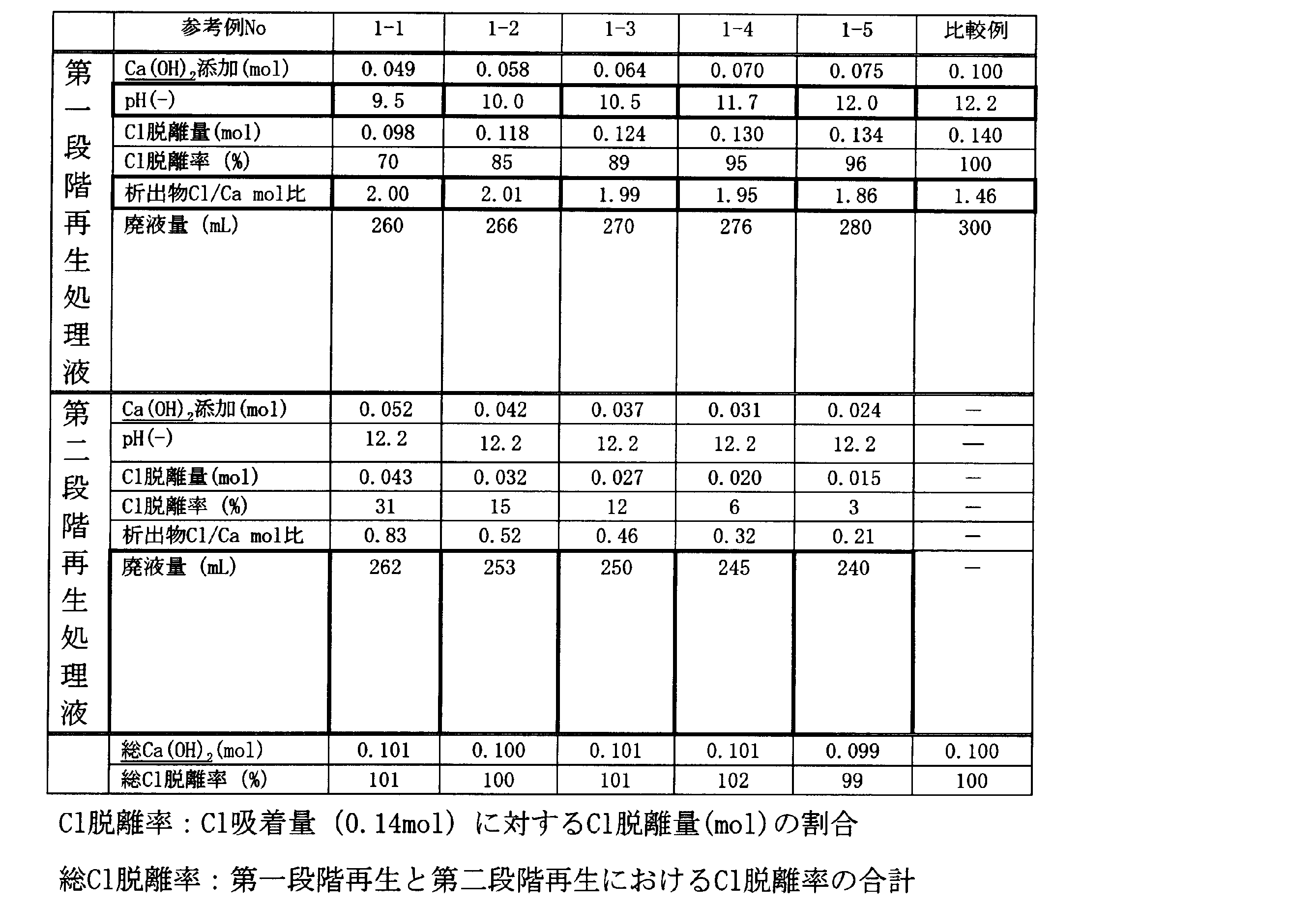
CaCl2のCa2+とCl-のモル比は1:2であるので、参考例1-1~1-5及び比較例の析出物のCl/Camol比が2に近いほど再生処理液中のCaCl2の純度が高く、値が小さいほどCaCl2の純度が低いことになる。そこで、表2の結果を見ると、比較例では、析出物のCl/Camol比が1.46と低かったのに対し、完全再生前で一旦消石灰添加を停止し、第一段階再生処理液として再生処理液を取り出した参考例1-1~1-5では、Cl/Camol比が1.86以上であった。このCl/Camol比1.86は、重量換算すると、CaCl2純度95.2%であり、不純物としてCa(OH)2を4.2%しか含まないことになる。また、pH11.7以下(Cl脱離率95%)の参考例1-1~1-4では、Cl/Camol比が1.95以上となっている。このCl/Camol比は、重量換算すると、CaCl2純度98.3%であり、不純物としてCa(OH)2を1.7%しか含まないことになる。すなわち、第一段階再生処理液のpHが低いほど、あるいはCl脱離率が低いほど、再生処理液から回収されるCaCl2の純度は高くなる傾向にある。但し、第一段階再生処理液のpHが低いほど、あるいはCl脱離率が低いほど、第二段階再生処理液を回収する場合には、第二段階再生処理液の量が多くなる傾向にあるため、貯留設備が大きくなることが予測される。
以上の結果から、NaClを含有する資源採掘随伴水から、CaCl2を高純度で得ることができることが確認された。CaCl2を高純度で回収するためには、再生処理液のpHを計測、またはCl-イオン濃度を計測してCl脱離量を求め、それらが予め定めた設定値に達するまでに回収した再生処理液を濃縮・乾燥させる、すなわち、CaCl2純度が比較的高い再生処理液からCaCl2が得られるようにする必要があることがわかった。その設定値の範囲としては、pH計測の場合、pH10.0~12.0の間に設定すること、Cl-イオン濃度計測の場合、Cl-イオン吸着量の85~96%の間に設定することが好ましい。
(参考例2)
参考例2では、CSG資源採掘随伴水を樹脂塔に通水しNaHCO3を回収し、純水で洗浄するまで参考例1と同様の操作を行った。その後、充填塔に、再生処理液のpH及びCl-イオン濃度を測定しながら、参考例1-4で得られた第二段階再生処理液(CaCl2の純度は低い)を間欠的に添加した。第二段階再生処理液を全て使用した後、5w/v%のCa(OH)2スラリーを間欠的に添加した。そして、再生処理液のpHが11.7に達した時点で、充填塔内の再生処理液を取り出した。取り出した再生処理液(第一段階再生処理液)は、エバポレータによる減圧蒸留による濃縮及びホットプレートによる蒸発乾固を行って、CaCl2を含む溶解塩類を析出させた。析出物を再度純水に微量溶解しCa2+とCl-濃度を測定して、析出物中の両元素のモル比を確認した。
参考例2では、CSG資源採掘随伴水を樹脂塔に通水しNaHCO3を回収し、純水で洗浄するまで参考例1と同様の操作を行った。その後、充填塔に、再生処理液のpH及びCl-イオン濃度を測定しながら、参考例1-4で得られた第二段階再生処理液(CaCl2の純度は低い)を間欠的に添加した。第二段階再生処理液を全て使用した後、5w/v%のCa(OH)2スラリーを間欠的に添加した。そして、再生処理液のpHが11.7に達した時点で、充填塔内の再生処理液を取り出した。取り出した再生処理液(第一段階再生処理液)は、エバポレータによる減圧蒸留による濃縮及びホットプレートによる蒸発乾固を行って、CaCl2を含む溶解塩類を析出させた。析出物を再度純水に微量溶解しCa2+とCl-濃度を測定して、析出物中の両元素のモル比を確認した。
次に、充填塔内に純水を導入し、消石灰スラリーを間欠的に添加し、再生処理液のpHを測定し、消石灰スラリーを加えてもpHが12.2以上に上がらない状態とした。この段階の再生処理液(第二段階再生処理液)を充填塔から取り出し、第二段階再生処理液中のCl-イオンを計測した。そして、第一段階再生処理液のCl-イオン脱離量と合わせた総Cl脱離率を算出し、完全に再生できたことを確認した。
参考例2の結果としては、pH11.7に達した時点で取り出した第一段階再生処理液を濃縮・蒸発乾固させて得られた析出物のCl/Camol比は1.96であり、CaCl2を高純度で回収できることが確認できた。完全再生まで(再生処理液のpHが12.2になるまで)に添加した新規の消石灰量は0.071mol(0.142eq)であり、被処理水の通水で吸着したCl-イオン量(0.140mol=0.140eq)と等量であった。このことから、完全再生には本来Cl-イオン吸着量と等量以上のCa(OH)2が必要だが、前のサイクルの再生における第二段階再生処理液を再生剤として使用することにより、1回の再生あたりに使用する新規の消石灰量はCl-イオン吸着量とほぼ等量で済むことが確認できた(表2)。
また、消石灰とともに、第二段階再生処理液を再生剤として使用しても、CaCl2を高純度で回収することができることが確認できた。その結果、必要最小限のCa(OH)2の添加で、弱塩基性イオン交換樹脂の再生が可能であり、Ca(OH)2のロス・廃棄がほとんどなく、再生に関わるランニングコストを低減できることが示された。
(実施例1~5の模擬排水)
実施例1~5では、表3に示す組成の模擬排水を調整した。模擬排水中のCl-濃度、各炭酸濃度は、実際の資源採掘随伴水に前処理・濃縮工程を実施したあとの濃度として想定される範囲内の値とした。
実施例1~5では、表3に示す組成の模擬排水を調整した。模擬排水中のCl-濃度、各炭酸濃度は、実際の資源採掘随伴水に前処理・濃縮工程を実施したあとの濃度として想定される範囲内の値とした。

(実施例1)
pH9.5の模擬排水にCO2ガスを吹き込んで、pH6.7~9に調整した模擬排水、及び比較のためCO2ガスを吹き込まず、pH9.5の模擬排水を、弱塩基性アクリル系イオン交換樹脂(オルガノ社製、アンバーライトIRA-67、交換容量1.6eq/L-R)を200mL充填した充填塔に通水した。なお、充填塔の弱塩基性アクリル系イオン交換樹脂は、あらかじめCO2溶解水を通水して、弱塩基性イオン交換樹脂の全量をH2CO3型に変換した状態にしてから、上記模擬排水をSV1.0(1/h)で通水した。充填塔から排出された処理水のHCO3 -、CO3 2-、Cl-の濃度を測定し、これら合計アニオンの総量が延べ0.2当量になった時点で、模擬排水の通水を停止した。Na+イオン濃度、処理水pHを確認し、得られた処理水のNaHCO3、Na2CO3、NaCl、NaOH濃度をもとに、濃縮・乾燥で固形物として析出させた場合のNaHCO3の純度及び回収量を求めた。その結果を表4にまとめた。ここで、処理水中に含有されるNaHCO3濃度はHCO3 -濃度(mlo/L)から求めた。HCO3 -濃度は、Mアルカリ度とPアルカリ度を測定して求めた。
[NaHCO3](g/L)=[HCO3 -](mol/L)×(84/61)
[HCO3 -](mol/L)=Mアルカリ度-Pアルカリ度(mol/L)
また、Na2CO3濃度は、CO3 2-濃度から求め、CO3 2-濃度はMアルカリ度とpHから求めた。
[Na2CO3](g/L)=[CO3 2-](mol/L)×(106/60)
[CO3 2-]=2×(Mアルカリ度-10(pH-14))(mol/L)
模擬排水1LあたりのNaHCO3回収量(g/L)は、濃縮乾燥後の析出物量×純度(%)で算出した。
pH9.5の模擬排水にCO2ガスを吹き込んで、pH6.7~9に調整した模擬排水、及び比較のためCO2ガスを吹き込まず、pH9.5の模擬排水を、弱塩基性アクリル系イオン交換樹脂(オルガノ社製、アンバーライトIRA-67、交換容量1.6eq/L-R)を200mL充填した充填塔に通水した。なお、充填塔の弱塩基性アクリル系イオン交換樹脂は、あらかじめCO2溶解水を通水して、弱塩基性イオン交換樹脂の全量をH2CO3型に変換した状態にしてから、上記模擬排水をSV1.0(1/h)で通水した。充填塔から排出された処理水のHCO3 -、CO3 2-、Cl-の濃度を測定し、これら合計アニオンの総量が延べ0.2当量になった時点で、模擬排水の通水を停止した。Na+イオン濃度、処理水pHを確認し、得られた処理水のNaHCO3、Na2CO3、NaCl、NaOH濃度をもとに、濃縮・乾燥で固形物として析出させた場合のNaHCO3の純度及び回収量を求めた。その結果を表4にまとめた。ここで、処理水中に含有されるNaHCO3濃度はHCO3 -濃度(mlo/L)から求めた。HCO3 -濃度は、Mアルカリ度とPアルカリ度を測定して求めた。
[NaHCO3](g/L)=[HCO3 -](mol/L)×(84/61)
[HCO3 -](mol/L)=Mアルカリ度-Pアルカリ度(mol/L)
また、Na2CO3濃度は、CO3 2-濃度から求め、CO3 2-濃度はMアルカリ度とpHから求めた。
[Na2CO3](g/L)=[CO3 2-](mol/L)×(106/60)
[CO3 2-]=2×(Mアルカリ度-10(pH-14))(mol/L)
模擬排水1LあたりのNaHCO3回収量(g/L)は、濃縮乾燥後の析出物量×純度(%)で算出した。

表3及び表4から分かるように、遊離炭酸を除く全炭酸物質の物質量に対するCl-イオンの物質量の比が6.0の模擬排水では、CO2ガスでpHを6.7~8.5の範囲で調整することにより、純度の高いNaHCO3を高収量で回収できた。特に、pH6.7~8.0ではより純度が高く、より高収量でNaHCO3を回収することができた。
(実施例2)
pH6.0の模擬排水に空気を吹き込んで、pH6.5~8.4に調整した模擬排水、及び比較のため空気を吹き込まず、pH6.0の模擬排水を用いたこと以外は、実施例1と同様に行った。実施例2の結果を表5にまとめた。
pH6.0の模擬排水に空気を吹き込んで、pH6.5~8.4に調整した模擬排水、及び比較のため空気を吹き込まず、pH6.0の模擬排水を用いたこと以外は、実施例1と同様に行った。実施例2の結果を表5にまとめた。

表3及び表5から分かるように、遊離炭酸を除く全炭酸物質の物質量に対するCl-イオンの物質量の比が6.0の模擬排水では、空気でpHを6.5~8.4の範囲で調整することにより、純度の高いNaHCO3を高収量で回収できた。特に、pH6.5~8.0ではより純度が高く、より高収量でNaHCO3を回収することができた。
(実施例3)
pH9.5の模擬排水にCO2ガスを吹き込んで、pH6.4~8.0に調整した模擬排水、及び比較のためCO2ガスを吹き込まず、pH9.5の模擬排水を用いたこと以外は、実施例1と同様に行った。実施例3の結果を表6にまとめた。
pH9.5の模擬排水にCO2ガスを吹き込んで、pH6.4~8.0に調整した模擬排水、及び比較のためCO2ガスを吹き込まず、pH9.5の模擬排水を用いたこと以外は、実施例1と同様に行った。実施例3の結果を表6にまとめた。

表3及び表6から分かるように、遊離炭酸を除く全炭酸物質の物質量に対するCl-イオの物質量の比が2.0の模擬排水では、CO2ガスでpHを6.4~8.0の範囲で調整することにより、純度の高いNaHCO3を高収量で回収できた。特に、pH6.7~8.0ではより純度が高く、より高収量でNaHCO3を回収することができた。
(実施例4)
pH9.5の模擬排水にCO2ガスを吹き込んで、pH6.1~8.0に調整した模擬排水、及び比較のためCO2ガスを吹き込まず、pH9.5の模擬排水を用いたこと以外は、実施例1と同様に行った。実施例4の結果を表7にまとめた。
pH9.5の模擬排水にCO2ガスを吹き込んで、pH6.1~8.0に調整した模擬排水、及び比較のためCO2ガスを吹き込まず、pH9.5の模擬排水を用いたこと以外は、実施例1と同様に行った。実施例4の結果を表7にまとめた。

表3及び表7から分かるように、遊離炭酸を除く全炭酸物質の物質量に対するCl-イオンの物質量の比が1.5の模擬排水では、CO2ガスでpHを6.1~6.4の範囲で調整することにより、純度の高いNaHCO3を高収量で回収できた。特に、pH6.1で、より純度の高いNaHCO3を回収できた。
(実施例5)
pH9.5の模擬排水にCO2ガスを吹き込んで、pH5.8~6.5に調整した模擬排水、及び比較のためCO2ガスを吹き込まず、pH9.5の模擬排水を用いたこと以外は、実施例1と同様に行った。実施例5の結果を表8にまとめた。
pH9.5の模擬排水にCO2ガスを吹き込んで、pH5.8~6.5に調整した模擬排水、及び比較のためCO2ガスを吹き込まず、pH9.5の模擬排水を用いたこと以外は、実施例1と同様に行った。実施例5の結果を表8にまとめた。

表3及び表8から分かるように、遊離炭酸を除く全炭酸物質の物質量に対するCl-イオンの物質量の比が0.9の模擬排水では、CO2ガスでpHを5.8~6.2の範囲で調整することにより、純度の高いNaHCO3を高収量で回収できた。特に、pH5.8で、より純度の高いNaHCO3を回収できた。
以上、実施例1~5の結果から、資源採掘随伴水にNaClと炭酸イオン・重炭酸イオンが共存し、その含有量・存在比率が様々に変化しても、遊離炭酸を除く全炭酸物質の物質量に対するCl-イオン物質量の比に応じて、資源採掘随伴水のpHを調整することにより、純度の高いNaHCO3を安定的に取り出せることが確認できた。
1 溶解塩類製造装置、2,3 炭酸水素ナトリウム製造装置、10,46 排水貯留槽、12,48a,48b 排水流入ライン、14,50a,50b 排水ポンプ、16,58 充填塔、18,60 処理水排出ライン、19 積算流量計、20,62 処理水槽、21,30,31,64,66 Cl-イオンセンサ、22,86 Ca(OH)2貯留槽、24,88 Ca(OH)2流入ライン、26,90 Ca(OH)2ポンプ、28,70 pHセンサ、32,54,92 ブロワ、34,94 空気流入ライン、36a,36b,98 再生処理液排出ライン、38a,38b 再生処理液貯留槽、40,72 制御部、42,74 濃縮装置、44,76 乾燥装置、52 pH調整塔、56 ガス流入ライン、68 アルカリ度計、78 HCl貯留槽、80 HCl添加ライン、82 HClポンプ、84 pH調整槽。
Claims (7)
- NaCl及び炭酸物質を含有するNaCl含有水を陰イオン交換樹脂に通水し、NaHCO3を回収する回収工程を備える炭酸水素ナトリウムの製造方法であって、
前記NaCl含有水を陰イオン交換樹脂に通水する際に、前記NaCl含有水に含まれる遊離炭酸を除いた全炭酸物質の物質量に対するCl-イオンの物質量の比に応じて、前記NaCl含有水のpHを調整することを特徴とする炭酸水素ナトリウムの製造方法。 - 前記NaCl含有水のpHを調整する前に前記比に関する基準値を設定し、
前記NaCl含有水のpHを調整するときは、前記比が前記基準値より小さい場合に、前記比が前記基準値より大きい場合と比べて、前記NaCl含有水のpHが低くなるようにすることを特徴とする請求項1記載の炭酸水素ナトリウムの製造方法。 - 前記NaCl含有水に含まれる遊離炭酸を除いた全炭酸物質の物質量に対するCl-イオンの物質量の比が2以上の場合は、前記NaCl含有水のpHを6.5以上~8.5以下に調整し、前記NaCl含有水に含まれる遊離炭酸を除いた全炭酸物質の物質量に対するCl-イオンの物質量の比が2未満の場合は、前記NaCl含有水のpHを5.6以上~6.5未満に調整することを特徴とする請求項1記載の炭酸水素ナトリウムの製造方法。
- 前記NaCl含有水のpH調整は、前記NaCl含有水にCO2ガス、塩酸、又は空気を添加することにより行うことを特徴とする請求項1記載の炭酸水素ナトリウムの製造方法。
- NaCl及び炭酸物質を含有するNaCl含有水は、資源採掘随伴水であることを特徴とする請求項1に記載の炭酸水素ナトリウムの製造方法。
- 前記陰イオン交換樹脂は、炭酸型の陰イオン交換樹脂であることを特徴とする請求項1に記載の炭酸水素ナトリウムの製造方法。
- 陰イオン交換樹脂を充填した充填塔と、
NaCl及び炭酸物質を含有するNaCl含有水を前記充填塔に通水し、NaHCO3を回収する回収手段と、
前記NaCl含有水を陰イオン交換樹脂に通水する際に、前記NaCl含有水に含まれる遊離炭酸を除いた全炭酸物質の物質量に対するCl-イオンの物質量の比に応じて、前記NaCl含有水にpH調整剤を添加して、前記NaCl含有水のpHを調整するpH調整手段と、を備えることを特徴とする炭酸水素ナトリウムの製造装置。
Applications Claiming Priority (2)
| Application Number | Priority Date | Filing Date | Title |
|---|---|---|---|
| JP2012287988A JP6159527B2 (ja) | 2012-12-28 | 2012-12-28 | 炭酸水素ナトリウムの製造方法及び炭酸水素ナトリウムの製造装置 |
| JP2012-287988 | 2012-12-28 |
Publications (1)
| Publication Number | Publication Date |
|---|---|
| WO2014104247A1 true WO2014104247A1 (ja) | 2014-07-03 |
Family
ID=51021321
Family Applications (1)
| Application Number | Title | Priority Date | Filing Date |
|---|---|---|---|
| PCT/JP2013/084991 Ceased WO2014104247A1 (ja) | 2012-12-28 | 2013-12-26 | 炭酸水素ナトリウムの製造方法及び炭酸水素ナトリウムの製造装置 |
Country Status (2)
| Country | Link |
|---|---|
| JP (1) | JP6159527B2 (ja) |
| WO (1) | WO2014104247A1 (ja) |
Citations (2)
| Publication number | Priority date | Publication date | Assignee | Title |
|---|---|---|---|---|
| JPS54125185A (en) * | 1978-03-16 | 1979-09-28 | Ici Australia Ltd | Purification of brine |
| JPH07507032A (ja) * | 1991-11-26 | 1995-08-03 | ブルナー・モンド(ユーケイ)リミテッド | アルカリ金属炭酸塩の製造 |
-
2012
- 2012-12-28 JP JP2012287988A patent/JP6159527B2/ja active Active
-
2013
- 2013-12-26 WO PCT/JP2013/084991 patent/WO2014104247A1/ja not_active Ceased
Patent Citations (2)
| Publication number | Priority date | Publication date | Assignee | Title |
|---|---|---|---|---|
| JPS54125185A (en) * | 1978-03-16 | 1979-09-28 | Ici Australia Ltd | Purification of brine |
| JPH07507032A (ja) * | 1991-11-26 | 1995-08-03 | ブルナー・モンド(ユーケイ)リミテッド | アルカリ金属炭酸塩の製造 |
Non-Patent Citations (1)
| Title |
|---|
| ROBERT KUNIN: "Ion exchange in chemical synthesis", INDUSTRIAL AND ENGINEERING CHEMISTRY, vol. 56, no. 1, January 1964 (1964-01-01), pages 35 - 39 * |
Also Published As
| Publication number | Publication date |
|---|---|
| JP6159527B2 (ja) | 2017-07-05 |
| JP2014129193A (ja) | 2014-07-10 |
Similar Documents
| Publication | Publication Date | Title |
|---|---|---|
| US12252409B2 (en) | Preparation of lithium carbonate from lithium chloride containing brines | |
| US8597521B1 (en) | Selective removal of silica from silica containing brines | |
| CA3059899C (en) | PROCESS FOR PREPARING LITHIUM CONCENTRATE FROM NATURAL BRINES CHARGED WITH LITHIUM AND ITS TRANSFORMATION INTO LITHIUM CHLORIDE OR LITHIUM CARBONATE | |
| US9222149B2 (en) | Preparation of lithium carbonate from lithium chloride containing brines | |
| US9012357B2 (en) | Lithium extraction composition and method of preparation thereof | |
| US9051827B1 (en) | Selective removal of silica from silica containing brines | |
| JP2021050133A (ja) | 鹹水からの水酸化リチウム一水和物の製造方法 | |
| JP2024539869A (ja) | 逆浸透を使用してリチウム化合物を生成するためのプロセス | |
| CA2029115C (en) | Method for removing sulfate ions from aqueous solution of alkali metal chloride | |
| JP6163326B2 (ja) | 溶解塩類の回収方法、溶解塩類の回収装置及び塩化カルシウムの製造方法 | |
| Abusultan et al. | A hybrid process combining ion exchange resin and bipolar membrane electrodialysis for reverse osmosis remineralization | |
| WO2014104248A1 (ja) | 溶解塩類の回収方法、溶解塩類の回収装置及び塩化カルシウムの製造方法 | |
| JP6159527B2 (ja) | 炭酸水素ナトリウムの製造方法及び炭酸水素ナトリウムの製造装置 | |
| JP2014151310A (ja) | 水処理方法及び水処理装置 | |
| AU2017246245B9 (en) | Mineral recovery and method for treatment of water having carbonate alkalinity | |
| Myers et al. | Synthetic-resin ion exchangers in water purification | |
| JPH03181384A (ja) | 純水製造装置の樹脂再生システム | |
| JP2012192341A (ja) | ホウフッ化物含有液の処理方法 | |
| JPS6234681B2 (ja) | ||
| SU1678771A1 (ru) | Способ получени минеральных веществ из морской воды | |
| Tanaka et al. | Technology for removing potassium ion from concentrated seawater by electrodialysis and solar salt dissolved in brine | |
| RU2183202C2 (ru) | Способ комплексной переработки природных минерализованных вод | |
| US12434983B2 (en) | Method for treating water to reduce the dissolved silica content thereof | |
| JP2004275948A (ja) | 硼素除去方法および硼素除去装置 | |
| Brown et al. | Brine Purification by Ion Exchange with Water Elution |
Legal Events
| Date | Code | Title | Description |
|---|---|---|---|
| 121 | Ep: the epo has been informed by wipo that ep was designated in this application |
Ref document number: 13869803 Country of ref document: EP Kind code of ref document: A1 |
|
| NENP | Non-entry into the national phase |
Ref country code: DE |
|
| 122 | Ep: pct application non-entry in european phase |
Ref document number: 13869803 Country of ref document: EP Kind code of ref document: A1 |