WO2014103736A1 - 測定装置 - Google Patents
測定装置 Download PDFInfo
- Publication number
- WO2014103736A1 WO2014103736A1 PCT/JP2013/083321 JP2013083321W WO2014103736A1 WO 2014103736 A1 WO2014103736 A1 WO 2014103736A1 JP 2013083321 W JP2013083321 W JP 2013083321W WO 2014103736 A1 WO2014103736 A1 WO 2014103736A1
- Authority
- WO
- WIPO (PCT)
- Prior art keywords
- excitation light
- temperature
- light source
- fluorescence
- unit
- Prior art date
- Legal status (The legal status is an assumption and is not a legal conclusion. Google has not performed a legal analysis and makes no representation as to the accuracy of the status listed.)
- Ceased
Links
Images


Classifications
-
- A—HUMAN NECESSITIES
- A61—MEDICAL OR VETERINARY SCIENCE; HYGIENE
- A61B—DIAGNOSIS; SURGERY; IDENTIFICATION
- A61B5/00—Measuring for diagnostic purposes; Identification of persons
- A61B5/44—Detecting, measuring or recording for evaluating the integumentary system, e.g. skin, hair or nails
- A61B5/441—Skin evaluation, e.g. for skin disorder diagnosis
-
- A—HUMAN NECESSITIES
- A61—MEDICAL OR VETERINARY SCIENCE; HYGIENE
- A61B—DIAGNOSIS; SURGERY; IDENTIFICATION
- A61B5/00—Measuring for diagnostic purposes; Identification of persons
- A61B5/72—Signal processing specially adapted for physiological signals or for diagnostic purposes
- A61B5/7203—Signal processing specially adapted for physiological signals or for diagnostic purposes for noise prevention, reduction or removal
-
- G—PHYSICS
- G01—MEASURING; TESTING
- G01N—INVESTIGATING OR ANALYSING MATERIALS BY DETERMINING THEIR CHEMICAL OR PHYSICAL PROPERTIES
- G01N21/00—Investigating or analysing materials by the use of optical means, i.e. using sub-millimetre waves, infrared, visible or ultraviolet light
- G01N21/62—Systems in which the material investigated is excited whereby it emits light or causes a change in wavelength of the incident light
- G01N21/63—Systems in which the material investigated is excited whereby it emits light or causes a change in wavelength of the incident light optically excited
- G01N21/64—Fluorescence; Phosphorescence
- G01N21/645—Specially adapted constructive features of fluorimeters
-
- A—HUMAN NECESSITIES
- A61—MEDICAL OR VETERINARY SCIENCE; HYGIENE
- A61B—DIAGNOSIS; SURGERY; IDENTIFICATION
- A61B5/00—Measuring for diagnostic purposes; Identification of persons
- A61B5/0059—Measuring for diagnostic purposes; Identification of persons using light, e.g. diagnosis by transillumination, diascopy, fluorescence
- A61B5/0071—Measuring for diagnostic purposes; Identification of persons using light, e.g. diagnosis by transillumination, diascopy, fluorescence by measuring fluorescence emission
Definitions
- the present invention relates to a measuring apparatus for measuring a measurement target substance present in a living body.
- anti-glycation cosmetics have been commercialized for the purpose of reducing AGEs (Advanced Glycation End Products) accumulated in the skin.
- AGEs are end products formed by a non-enzymatic sugar addition reaction (Maillard reaction) between a protein, a carbohydrate and a lipid. AGEs are yellowish brown, and some of them are fluorescent substances. In addition, AGEs have a property of forming a crosslink by binding to a nearby structural protein. In particular, cross-linking between AGEs and collagen constituting the dermis lowers the elasticity of the skin, and also causes problems such as wrinkles and dullness. Therefore, the health condition and aging of the skin can be evaluated by monitoring AGEs.
- Miillard reaction non-enzymatic sugar addition reaction
- the user can know the state of the skin, and thereby the need for skin care with a commercially available cream or the like that reduces AGEs. Can be recognized.
- the skin is irradiated with excitation light from at least one excitation light source and the intensity of fluorescence generated from the skin is used as a parameter.
- a measuring device for evaluating the above is disclosed.
- the excitation light necessary for obtaining the fluorescence of AGEs is ultraviolet light
- the excitation light source is selected from a light emitting diode (LED), a semiconductor laser (LD), a xenon lamp, a mercury lamp, and the like.
- the emission intensity and / or emission spectrum vary depending on the temperature of the excitation light source.
- the excitation light source is a light emitting diode, a semiconductor laser, or a xenon lamp
- the emission intensity and the emission spectrum change depending on the temperature of the excitation light source.
- the excitation light source is a mercury lamp
- the emission intensity varies depending on the temperature of the excitation light source.
- the fluorescence intensity emitted by the fluorescent substance in the skin irradiated with the excitation light changes. Therefore, although the skin state is constant, fluorescence with different intensity is detected depending on the temperature of the excitation light source.
- the fact that the detected fluorescence intensity is affected by the temperature of the excitation light source is not practically desirable as a measuring apparatus for evaluating the skin condition.
- the present invention has been made to solve the above-described problems, and its purpose is to perform measurement that can appropriately evaluate the skin condition while suppressing variation in fluorescence intensity caused by the temperature of the excitation light source.
- An apparatus and a correction method are provided.
- a measurement apparatus receives an excitation light source that generates excitation light to irradiate a measurement site of a living body, and fluorescence generated from the measurement site by irradiation of the excitation light.
- a correction method includes an irradiation step of irradiating a measurement site of a living body with excitation light generated by an excitation light source, and the measurement by irradiation with the excitation light.
- the present invention it is possible to correct the intensity of the fluorescence received by the light receiving unit based on the temperature of the excitation light source measured by the temperature measuring unit, resulting in the temperature of the excitation light source.
- FIG. 1 It is a block diagram which shows an example of a structure of the measuring apparatus which concerns on embodiment of this invention. It is a figure which shows an example of the external appearance of the measuring apparatus which concerns on embodiment. It is sectional drawing which expands and shows a part of measuring apparatus which concerns on embodiment.
- (A) is a graph showing the correlation between the temperature of the excitation light source and the intensity of the excitation light
- (b) is a graph showing the correlation between the temperature of the excitation light source and the intensity of fluorescence. It is a graph which shows the spectrum change of excitation light when changing the temperature of an excitation light source. It is a graph which shows the correlation with the peak wavelength of excitation light, and the intensity
- the measurement apparatus irradiates the human skin with the excitation light from the probe, and detects the fluorescence generated by the irradiated excitation light, thereby detecting the late-stage saccharification-reactive organism (hereinafter referred to as the glycation-reactive organism) present in the skin.
- AGEs the late-stage saccharification-reactive organism
- the measuring apparatus is not limited to AGEs, and may measure other substances. That is, any device that evaluates the amount of the target substance by irradiating the skin with excitation light and detecting the intensity of the fluorescence emitted from the target substance corresponds to the measurement apparatus according to the present invention.
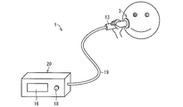
- FIG. 2 is a schematic diagram showing an example of the appearance of the measuring apparatus 1.
- the measuring apparatus 1 includes a main body unit 20, a bundle fiber unit 19, and a probe 13.
- the main body 20 is connected to the probe 13 via the bundle fiber 19.
- the main body unit 20 includes a display unit 16 and a power switch 18.
- the bundle fiber portion 19 is composed of a bundle of one or more excitation optical fibers and one or more fluorescent light guide fibers.
- a probe 13 is provided at the tip of the bundle fiber portion 19, and the excitation light 2 is irradiated from the probe 13 toward the measurement site 3. Further, the fluorescence generated from the measurement site 3 by the irradiation of the excitation light is introduced from the probe 13 into the bundle fiber portion 19 and guided to the main body portion 20.
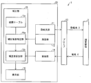
- FIG. 1 is a block diagram showing an example of the configuration of the measuring apparatus 1 shown in FIG.
- the main body of the measuring apparatus 1 includes an excitation light source 11, a temperature measuring unit 12, a light receiving unit 14, a correcting unit 15, and a display unit 16.
- the excitation light source 11 generates the excitation light 2 that irradiates the measurement site 3.
- the excitation light 2 generated by the excitation light source 11 is irradiated from the probe 13 to the measurement site 3 through the bundle fiber portion 19 (irradiation step).
- Power is supplied to the excitation light source 11 from a power source (not shown).
- This power source is composed of, for example, a constant current source having a voltage of 10 V or less and a current of about 500 mA or less.
- the excitation light source 11 a semiconductor light emitting element such as a light emitting diode (LED) or a laser diode (LD) can be used.
- the excitation light source 11 is not limited to the semiconductor light emitting element, and for example, a mercury lamp, a xenon lamp, or the like can be used.
- the excitation light source 11 may be configured to include a spectroscope and an optical filter. By providing the spectroscope and the optical filter, it is possible to irradiate the measurement site 3 only with the excitation light 2 having a specific wavelength.
- the AGEs contained in the skin at the measurement site 3 are excited to generate fluorescence 4.
- the fluorescence 4 generated from the AGEs is received by the light receiving unit 14 through the bundle fiber unit 19.
- the excitation light 2 generated by the excitation light source 11 preferably includes a wavelength of 300 nm or more and 420 nm or less, which is an ultraviolet A wave (UVA) region.
- UVA ultraviolet A wave
- the temperature measuring unit 12 is a temperature sensor for measuring the temperature of the excitation light source 11, and converts the temperature of the excitation light source 11 into an electrical signal (temperature measurement step).
- the temperature measuring unit 12 includes a thermocouple, a resistance thermometer, a radiation thermometer, and the like.
- the temperature measuring unit 12 is arranged so as to be in contact with the excitation light source 11 directly or via a heat conductive material having a thermal conductivity of 0.1 W / m ⁇ K or more.
- a heat conductive material having a thermal conductivity of 0.1 W / m ⁇ K or more for example, heat radiation grease or metal can be considered.
- the temperature measuring unit 12 and the excitation light source 11 are connected via a metal, the metal is highly conductive, so the temperature measuring unit 12 and the excitation light source 11 are electrically connected, and the parasitic capacitance increases. This may cause noise in the emission intensity of the excitation light source 11. Therefore, it is preferable that the temperature measuring unit 12 is in contact with the excitation light source 11 through heat-dissipating grease having high insulation properties.
- the electrical signal generated by the temperature measurement unit 12 is converted into a temperature signal indicating the temperature of the excitation light source 11 by a temperature signal conversion circuit (not shown), and then output to the correction unit 15.
- This temperature signal conversion circuit may be a circuit that generates a temperature signal corresponding to the thermocouple generation voltage based on the thermocouple generation voltage-temperature table, particularly when a thermocouple is used as the temperature measuring unit 12.
- the light receiving unit 14 is a light receiving sensor that receives the fluorescence 4 generated from the measurement site 3 by irradiation of the excitation light 2.
- the light receiving unit 14 converts the received fluorescence 4 into an electrical signal corresponding to the intensity of the fluorescence 4 (light receiving step).
- the light receiving unit 14 includes a spectroscope, a photodiode (PD), a phototransistor, a photoresistor, a solar cell, a photomultiplier tube, a CCD (charge-coupled device) image sensor, a CMOS (complementary metal-oxide-semiconductor) image sensor, and the like.
- PD photodiode
- CMOS complementary metal-oxide-semiconductor
- the electrical signal generated by the light receiving unit 14 is converted into an intensity signal indicating the intensity of fluorescence by a not-shown received light signal conversion circuit, and then output to the correction unit 15.
- the light reception signal conversion circuit may include a picoampere order minute current detection circuit, or may include an amplification circuit that amplifies the electrical signal generated by the light receiving unit 14.
- the correction unit 15 corrects the intensity of the fluorescence based on the temperature of the excitation light source 11 measured by the temperature measurement unit 12 (correction step).
- the correcting unit 15 includes a correction coefficient specifying unit (specifying unit) 15a, a correction value calculating unit (calculating unit) 15b, and a correlation table 15c.
- the correction coefficient specifying unit 15 a specifies a correction coefficient for correcting the intensity of the fluorescence 4 received by the light receiving unit 14 based on the temperature of the excitation light source 11 measured by the temperature measuring unit 12. Specifically, when the temperature signal indicating the temperature of the excitation light source 11 measured by the temperature measuring unit 12 is input, the correction coefficient specifying unit 15a refers to the correlation table 15c, and thereby the excitation indicated in the temperature signal. A correction coefficient corresponding to the temperature of the light source 11 is specified and output to the correction value calculation unit 15b.
- the correction value calculation unit 15b calculates the correction value of the intensity of the fluorescence 4 received by the light receiving unit 14 using the correction coefficient specified by the correction coefficient specifying unit 15a. Specifically, the correction value calculation unit 15b calculates the correction value by correcting the intensity (actual value) of the fluorescence 4 received by the light receiving unit 14 using the correction coefficient specified by the correction coefficient specifying unit 15a. To do. The correction value calculation unit 15b outputs the calculated correction value to the display unit 16 and causes the display unit 16 to display the correction value.
- the correlation table 15 c is a table for managing a correction coefficient for correcting the intensity of the fluorescence 4.
- a correction coefficient corresponding to the temperature of the excitation light source 11 is registered in advance. Details of the correction of the intensity of the fluorescence 4 in the correction unit 15 will be described later.
- the display unit 16 displays a measurement analysis result including a correction value of the intensity of the fluorescence 4 corrected by the correction unit.
- the display unit 16 can display video and information, and includes, for example, a personal computer, a television, a liquid crystal display, an organic EL display, a plasma display, an LED display, a 7-segment display, and other various display devices.
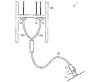
- FIG. 3 is an enlarged cross-sectional view showing a part of the measuring apparatus 1 shown in FIGS.
- the excitation light source 11 is connected to an excitation optical fiber 19a.
- a fluorescent light guide fiber 19 b is connected to the light receiving unit 14.
- the temperature measuring unit 12 is arranged so as to be in contact with the excitation light source 11 directly or through a heat conductive material.
- the excitation light 2 generated by the excitation light source 11 is introduced into the excitation optical fiber 19a and irradiated to the measurement site 3 from the probe 13. Further, the fluorescence 4 generated from the measurement site 3 is introduced into the fluorescence light guiding fiber 19b and received by the light receiving unit 14.
- a lens, an optical filter, a spectroscope, or the like may be inserted between the excitation light source 11 and the excitation optical fiber 19a.
- a lens, an optical filter, a spectroscope, or the like may be inserted between the light receiving unit 14 and the fluorescent light guiding fiber 19b.
- the measurement apparatus 1 is configured to directly irradiate the measurement site 3 with the excitation light 2 from the excitation light source 11 without using the bundle fiber unit 19 and directly receive the fluorescence 4 generated from the measurement site 3 by the light receiving unit 14. It may be.
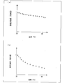
- FIG. 4A is a graph showing the correlation between the temperature of the excitation light source 11 and the intensity of the excitation light 2
- FIG. 4B is the correlation between the temperature of the excitation light source 11 and the intensity of the fluorescence 4. It is a graph which shows a relationship.
- the horizontal axis indicates the temperature of the excitation light source 11
- the vertical axis indicates the intensity of the excitation light 2
- the intensity of the excitation light 2 at each temperature is shown as a relative value when the intensity of 2 is 1.
- the horizontal axis indicates the temperature of the excitation light source 11 and the vertical axis indicates the intensity of the fluorescence 4.
- the intensity of fluorescence 4 at each temperature is shown as a relative value when the intensity of 4 is 1.
- the intensity of fluorescence 4 shown in FIG. 4B is obtained by placing a solid dermis model on a white plate mixed with a conjugate of bovine serum albumin (BSA) and AGE in an agarose gel, and applying excitation light 2 from above.
- BSA bovine serum albumin
- the intensity of the excitation light 2 emitted from the excitation light source 11 gradually decreases as the temperature of the excitation light source 11 increases.
- the intensity of the fluorescence 4 received by the light receiving unit 14 also decreases as the temperature of the excitation light source 11 increases.
- the decrease rate is the decrease rate of the excitation light 2. It is larger than that.
- the correlation between the temperature of the excitation light source 11 and the intensity of the fluorescence 4 shown in FIGS. 4A and 4B shows the intensity of the excitation light 2, the agarose gel concentration, and the concentration of the BSA-AGE conjugate. Even in the case of changing, almost the same result was obtained.
- the inventors of the present application have found that the rate of decrease of the excitation light 2 accompanying the increase in the temperature of the excitation light source 11 is greater than the rate of decrease of the excitation light 2. This is because the peak wavelength of the excitation light 2 is shifted in addition to a decrease in the intensity of the excitation light 2 as the temperature of the excitation light source 11 changes.
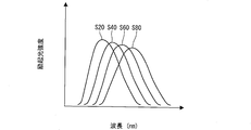
- FIG. 5 is a graph showing changes in the spectrum of the excitation light 2 when the temperature of the excitation light source 11 is changed.
- the horizontal axis indicates the wavelength of the excitation light 2 and the vertical axis indicates the intensity of the excitation light 2.
- S20, S40, S60, and S80 show the spectrum of the excitation light 2 when the temperature of the excitation light source 11 is 20 ° C., 40 ° C., 60 ° C., and 80 ° C., respectively.
- the center wavelength of the excitation light 2 shifts to the long wavelength side.
- the peak wavelength of the excitation light 2 tends to shift by about 1.8 nm to the longer wavelength side.
- the temperature of the excitation light source 11 such as an LED reaches 80 ° C. or higher, and therefore the shift amount of the peak wavelength of the excitation light 2 is 6 nm from the peak wavelength at 20 ° C. As described above, the wavelength shifts to the long wavelength side.
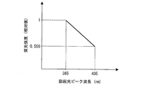
- FIG. 6 is a graph showing the correlation between the peak wavelength of the excitation light 2 and the intensity of the fluorescence 4.
- FIG. 6 shows the intensity of the fluorescence 4 received by the light receiving unit 14 when the peak wavelength of the excitation light 2 is changed while the intensity of the excitation light 2 is kept constant, and the horizontal axis indicates the excitation light 2.
- the vertical axis indicates the intensity of the fluorescence 4 (relative value when the intensity of the fluorescence 4 where the peak wavelength of the excitation light 2 is 365 nm is 1).
- the peak wavelength of the excitation light 2 is shifted by the change in the temperature of the excitation light source 11, thereby changing the intensity of the fluorescence 4.
- the temperature of the excitation light source 11 further affects the intensity of the fluorescence 4.
- the peak wavelength of the fluorescence 4 is shifted as the wavelength of the excitation light 2 is shifted.
- the peak wavelength of the fluorescence 4 is shifted by about 20 nm to the long wavelength side.
- the transmittance of the fluorescence 4 with respect to the optical filter has wavelength dependency. For this reason, when the peak wavelength of the fluorescence 4 is shifted, the transmittance of the fluorescence 4 with respect to the optical filter is lowered, so that the intensity of the fluorescence 4 received by the light receiving unit 14 is greatly affected.
- the correction unit 15 corrects the intensity of the fluorescence 4 based on the temperature of the excitation light source 11 so as to suppress the variation in the intensity of the fluorescence 4 caused by the temperature of the excitation light source 11. Specifically, the correction unit 15 compares the temperature of the excitation light source 11 measured by the temperature measurement unit 12 and the intensity of the fluorescence 4 at a predetermined reference temperature selected from a temperature range that the excitation light source 11 can take. The intensity of the fluorescence 4 received by the light receiving unit 14 is corrected using the relative value (correction coefficient) of the intensity of the fluorescence 4 at a temperature other than the temperature.
- FIG. 7 is a graph for explaining the correction process in the correction unit 15.
- the graph shown in FIG. 7 corresponds to the graph showing the correlation between the temperature of the excitation light source 11 and the intensity of the fluorescence 4 received by the light receiving unit 14 shown in FIG.
- the intensity of the fluorescence 4 received by the light receiving unit 14 when the temperature of the excitation light source 11 is 20 ° C. is set to 1, and the Y intercept
- An approximate expression is obtained by the least square method using an exponential function that passes through 1 (solid line portion in FIG. 7).
- the relative value of each temperature with respect to the intensity of the fluorescence 4 when the excitation light source 11 is at 20 ° C. is obtained. This relative value may be associated with the temperature of the excitation light source 11 and registered in the correlation table 15c in advance.
- the correction coefficient specifying unit 15a refers to the correlation table 15c when a temperature signal indicating the temperature of the excitation light source 11 measured by the temperature measuring unit 12 is input. And the correction coefficient specific
- the correction value calculation unit 15b receives light using the relative value specified by the correction coefficient specifying unit 15a when the intensity signal indicated by the intensity signal indicating the intensity of the fluorescence 4 received by the light receiving unit 14 is input.
- the correction value is calculated by correcting the intensity of the fluorescence 4 received by the unit 14.
- the correction value calculation unit 15b calculates the correction value by dividing the measured value of the intensity of the fluorescence 4 by the relative value.
- strength of the fluorescence 4 can be correct
- the correlation table 15c may be created for each type of AGEs. Thereby, since it becomes possible to calculate a correction value using the relative value according to the kind of AGEs, a skin state can be evaluated more appropriately.
- the measurement apparatus 1 receives the excitation light source 11 that generates the excitation light 2 irradiated to the measurement site 3 and the fluorescence 4 that is generated from the measurement site 3 by the irradiation of the excitation light 2. , A temperature measuring unit 12 that measures the temperature of the excitation light source 11, and a correction unit that corrects the intensity of the fluorescence 4 received by the light receiving unit 14 based on the temperature of the excitation light source 11 measured by the temperature measuring unit 12. 15.
- the measuring apparatus 1 it is possible to correct the intensity of the fluorescence 4 received by the light receiving unit 14 based on the temperature of the excitation light source 11 measured by the temperature measuring unit 12. It is possible to appropriately evaluate the skin condition while suppressing the variation in the intensity of the fluorescence 4 due to the temperature of.
- the measurement device 1 can be reduced in size at low cost. For example, it is possible to change the current applied to the excitation light source 11 based on the temperature of the excitation light source 11 or to perform constant temperature control so that the temperature of the excitation light source 11 becomes a predetermined temperature.
- the current controller and constant temperature controller of the excitation light source 11 must be attached. Therefore, it is difficult to provide an inexpensive measuring device due to an increase in product cost.
- the intensity of the detected fluorescence 4 is corrected, so that the measuring apparatus can be configured with a simpler configuration without adding a current controller or a constant temperature controller of the excitation light source 11. It can be realized.
- FIG. 8 is a cross-sectional view showing a modification of the excitation light source 11 and the temperature measuring unit 12.
- the excitation light source 11 has a CAN type LED chip 11a bonded on a stem (base) 32, and is sealed by a cap 31 having a translucent plate 31a.
- the LED chip 11a may be bonded with solder or silver paste.
- the stem 32 is usually formed of a metal having good conductivity, and a hole 33 is formed on a side surface thereof.
- the temperature measuring unit 12 may be disposed so that the tip thereof is embedded in the hole 33 formed in the stem 32 having thermal conductivity. Although it is preferable that the depth of the hole 33 reaches just under the arrangement position of the LED chip a, it is not limited to this.
- the temperature measuring unit 12 can efficiently measure the heat of the LED chip 11a, and the size of the apparatus can be reduced by space saving. Is possible.
- the inside of the hole 33 may be filled with the heat radiation grease 41.
- the heat radiation grease 41 is viscous and does not disappear by flowing under its own weight. Filling the inside of the hole 33 with the heat radiation grease 41 reduces the risk that the temperature measuring unit 12 is detached from the hole 33 due to vibration or the like, and the temperature measuring unit 12 cannot normally measure the temperature of the excitation light source 11. The temperature of the excitation light source 11 can be measured stably.
- FIG. 9 is a front view showing another modification of the excitation light source 11 and the temperature measuring unit 12.
- the excitation light source 11 is a surface mount type LED package in which an LED chip 11a is mounted on the surface.
- the temperature measuring unit 12 may be fixed to the side surface of the excitation light source 11 with a screw 42.
- the thermal radiation grease 41 may be applied to the tip portion of the temperature measuring unit 12. As described above, the heat dissipation grease 41 is viscous and does not flow and disappear due to its own weight, and by applying the heat dissipation grease 41, the temperature of the excitation light source 11 can be stably measured.
- FIG. 10 is a cross-sectional view showing another modification of the excitation light source 11 and the temperature measuring unit 12. As shown in FIG. 10, the excitation light source 11 is obtained by mounting an LED chip 11 a on a substrate 50.
- the heat radiation wiring pattern 55 is made of a heat conductive material having a heat conductivity of 0.1 W / m ⁇ K or more.
- a via hole 56 is formed in the substrate 50, and the heat radiation wiring pattern 55 is wired to the back surface of the substrate 50 through the via hole 56.
- the LED chip 11 a is mounted on the heat radiation wiring pattern 55 on the surface side of the substrate 50 with solder 58.
- the positive electrode of the excitation light source 11 is connected to the anode wiring pattern 53 via the anode wire 51, and the negative electrode of the excitation light source 11 is connected to the cathode wiring pattern 54 via the cathode wire 52.
- the temperature measuring unit 12 may be fixed by screws 42 and a holding plate 57 so as to be in contact with the heat radiation wiring pattern 55 on the back surface of the substrate 50. Note that, by applying heat radiation grease to the tip of the temperature measuring unit 12, the temperature measuring unit 12 can stably measure the temperature of the excitation light source 11 mounted on the surface of the substrate 50.
- the heat flow from the excitation light source 11 to the temperature measurement unit 12 is the excitation light source 11 ⁇ solder 58 ⁇ heat radiation wiring pattern 55 ( ⁇ heat radiation grease) ⁇ temperature measurement unit 12. Any of them preferably has a high thermal conductivity of 0.1 W / m ⁇ K or more.
- the temperature measuring unit 12 can correctly measure the temperature of the LED chip 11a.
- the freedom degree of design can be improved by thermally connecting the excitation light source 11 (LED chip 11a) and the temperature measurement part 12 through the heat conductive substance which has high heat conductivity.
- FIG. 11 is a cross-sectional view showing still another modified example of the excitation light source 11 and the temperature measuring unit 12.
- the present modification is mainly different from Modification 3 in that a radiation thermometer 70 is used as the temperature measuring unit 12.
- the radiation plate 60 is fixed with screws 42 so as to be in contact with the heat radiation wiring pattern 55 on the back surface of the substrate 50.
- Heat radiation grease may be applied between the radiation plate 60 and the heat radiation wiring pattern 55.
- a radiation thermometer (temperature measuring unit) 70 for detecting infrared rays generated from the radiation plate 60 is arranged on the extension of the radiation plate 60 in the radiation direction.
- the radiation thermometer 70 in this modification is provided with the lens 71, the filter 72, and the PD chip 73, a radiation thermometer having another configuration may be used.
- the radiation thermometer 70 as the temperature measuring unit 12 as in this modified example, a spatial separation can be provided between the excitation light source 11 and the temperature measuring unit 12.
- the degree of freedom in design can be improved.
- the correcting unit 15 (particularly the correction coefficient specifying unit 15a and the correction value calculating unit 15b) of the measuring apparatus 1 may be realized by a logic circuit (hardware) formed in an integrated circuit (IC chip) or the like, or a CPU ( It may be realized by software using a Central Processing Unit.
- the measuring apparatus 1 includes a CPU that executes instructions of a program that is software that realizes each function, a ROM (Read Only Memory) in which the above-described program and various data are recorded so as to be readable by a computer (or CPU), or A storage device (these are referred to as “recording media”), a RAM (Random Access Memory) for expanding the program, and the like are provided.
- the objective of this invention is achieved when a computer (or CPU) reads the said program from the said recording medium and runs it.
- a “non-temporary tangible medium” such as a tape, a disk, a card, a semiconductor memory, a programmable logic circuit, or the like can be used.
- the program may be supplied to the computer via any transmission medium (such as a communication network or a broadcast wave) that can transmit the program.
- the present invention can also be realized in the form of a data signal embedded in a carrier wave in which the program is embodied by electronic transmission.
- a measurement apparatus includes an excitation light source that generates excitation light that irradiates a measurement site of a living body, a light receiving unit that receives fluorescence generated from the measurement site due to irradiation of the excitation light, and the excitation light source
- a temperature measuring unit (radiation thermometer 70) for measuring the temperature
- a correction unit for correcting the intensity of the fluorescence received by the light receiving unit based on the temperature of the excitation light source measured by the temperature measuring unit, It has.
- the correction method includes an irradiation step of irradiating a measurement site of a living body with excitation light generated by an excitation light source, and a light reception step of receiving fluorescence generated from the measurement site by irradiation of the excitation light. And a temperature measuring step for measuring the temperature of the excitation light source, and a correction step for correcting the intensity of the fluorescence received in the light receiving step based on the temperature of the excitation light source measured in the temperature measurement step. And.
- the intensity of the fluorescence received by the light receiving unit can be corrected based on the temperature of the excitation light source measured by the temperature measuring unit, the fluorescence caused by the temperature of the excitation light source can be corrected. It is possible to provide a measuring apparatus that can appropriately evaluate the skin condition while suppressing variations in strength.
- the measuring device can be miniaturized at low cost. For example, it is possible to change the current applied to the excitation light source based on the temperature of the excitation light source, or to perform constant temperature control so that the temperature of the excitation light source becomes a predetermined temperature.
- a current controller and a constant temperature controller for the excitation light source must be provided. Therefore, it is difficult to provide an inexpensive measuring device due to an increase in product cost.
- the intensity of the received fluorescence is corrected, so that it is possible to realize a measuring device with a simpler configuration without adding a current controller or a constant temperature controller of the excitation light source. .
- the measurement apparatus is the measurement apparatus according to aspect 1, wherein the correction unit determines the intensity of the fluorescence received by the light receiving unit based on the temperature of the excitation light source measured by the temperature measuring unit.
- the correction unit determines the intensity of the fluorescence received by the light receiving unit based on the temperature of the excitation light source measured by the temperature measuring unit.
- the calculation unit can calculate the correction value of the fluorescence intensity using the relative coefficient specified by the specifying unit.
- the correction coefficient is a temperature other than the reference temperature with respect to the intensity of the fluorescence at a predetermined reference temperature selected from a temperature range that the excitation light source can take. It may be a relative value of the intensity of the fluorescence.
- the calculation unit calculates a correction value of the fluorescence intensity using a relative value with respect to the fluorescence intensity received by the light receiving unit when the excitation light source is at a predetermined reference temperature.
- the calculation unit corrects the intensity of the fluorescence to the value at the reference temperature regardless of the temperature of the excitation light source, and suppresses the variation in the intensity of the fluorescence caused by the temperature of the excitation light source. it can.
- the correction unit further includes a correlation table in which a plurality of the relative values according to the temperature of the excitation light source are registered in advance.
- the unit may identify the relative value according to the temperature of the excitation light source measured by the temperature measuring unit from the correlation table.
- the specifying unit since the specifying unit specifies the relative value using the correlation table in which the relative value is registered in advance, it is received by the light receiving unit based on the temperature of the excitation light source measured by the temperature measuring unit.
- the relative value for correcting the fluorescence intensity can be easily specified.
- the temperature measuring unit is in contact with the excitation light source via a heat conductive material (heat radiation grease 41 / heat radiation wiring pattern 55). It may be.
- the temperature of the excitation light source can be efficiently transmitted to the temperature measurement unit via the heat conductive material.
- the degree of freedom of arrangement of the excitation light source and the temperature measuring unit can be improved.
- the excitation light source includes a light emitting element (LED chip 11a) that emits the excitation light, and a heat mounted on the light emitting element. It has a base (stem 32) having conductivity, and the temperature measuring unit may be embedded in the base.
- the heat of the light emitting element can be efficiently measured by the temperature measuring unit, and the apparatus can be reduced in size by saving space.
- the wavelength of the excitation light may be not less than 300 nm and not more than 420 nm.
- the AGEs can be reliably excited and the fluorescence generated from the AGEs can be appropriately measured.
- the present invention is not limited to the above-described embodiments, and various modifications are possible within the scope shown in the claims, and the embodiments can be obtained by appropriately combining technical means disclosed in different embodiments.
- the form is also included in the technical scope of the present invention.
- a new technical feature can be formed by combining the technical means disclosed in each embodiment.
- the present invention can also be expressed as follows. That is, the measurement apparatus according to the present invention includes a skin condition measurement including an excitation light irradiation unit that irradiates a living body with excitation light guided from an excitation light source, and a fluorescence light receiving unit that receives fluorescence generated by the irradiation of the excitation light.
- a temperature measurement unit that measures the temperature of the excitation light source
- a calculation unit that can calculate a relative value of the fluorescence (electric signal) from the temperature of the excitation light source, and an intensity (electrical signal) of the fluorescence (electric signal). Signal) and a correction unit for correcting the relative value.
- the calculation unit may be a correlation table obtained in advance from a correlation value between the temperature of the excitation light source and the intensity of the fluorescence (electric signal).
- the temperature measuring unit may be in contact with the excitation light source via a substance having high thermal conductivity.
- the temperature measuring unit may be processed into an excitation light source and buried.
- the excitation light may be light having a wavelength of 300 to 420 nm as a central wavelength.
- the present invention can be used in a measuring device that monitors fluorescent substances in the skin.
- it can be suitably used for a measuring device for monitoring AGEs for evaluating skin health and aging.
Landscapes
- Health & Medical Sciences (AREA)
- Life Sciences & Earth Sciences (AREA)
- Engineering & Computer Science (AREA)
- Physics & Mathematics (AREA)
- General Health & Medical Sciences (AREA)
- Pathology (AREA)
- Public Health (AREA)
- Signal Processing (AREA)
- Heart & Thoracic Surgery (AREA)
- Medical Informatics (AREA)
- Molecular Biology (AREA)
- Surgery (AREA)
- Animal Behavior & Ethology (AREA)
- Biophysics (AREA)
- Biomedical Technology (AREA)
- Veterinary Medicine (AREA)
- Artificial Intelligence (AREA)
- Dermatology (AREA)
- Computer Vision & Pattern Recognition (AREA)
- Physiology (AREA)
- Psychiatry (AREA)
- Nuclear Medicine, Radiotherapy & Molecular Imaging (AREA)
- Chemical & Material Sciences (AREA)
- Analytical Chemistry (AREA)
- Biochemistry (AREA)
- General Physics & Mathematics (AREA)
- Immunology (AREA)
- Investigating, Analyzing Materials By Fluorescence Or Luminescence (AREA)
Abstract
励起光源の温度に起因する蛍光の強度のばらつきを抑える。測定装置(1)は、測温部(12)により測定された励起光源(11)の温度に基づいて、受光部(14)により受光された蛍光(4)の強度を補正する補正部(15)を備える。
Description
本発明は、生体内に存在する測定対象物質を測定する測定装置に関する。
従来、抗糖化(抗加齢)化粧品として、肌に蓄積したAGEs(Advanced Glycation Endproducts;後期糖化反応生成物)の低減を目的としたものが商品化されている。
このAGEsは、タンパク質と、糖質および脂質との非酵素的糖付加反応(メイラード反応)によって形成される最終生成物である。AGEsは、黄褐色を呈し、その一部は蛍光を発する物質である。また、AGEsは、近くに存在する構造蛋白質と結合して架橋を形成する性質を有している。特にAGEsと真皮を構成しているコラーゲンとの架橋は、皮膚の弾力性を低下させ、また、しわやくすみの原因としても問題となっている。そのため、AGEsをモニタリングすることで、肌の健康状態および老化を評価することができる。
したがって、皮膚中に蓄積したAGEsの量を正確に評価できる測定装置を用いて、ユーザは肌の状態を知ることができ、これにより、AGEsを減少させる市販のクリームなどによる皮膚のケアの必要性を認識することができる。
皮膚状態を評価する測定装置としては、例えば、特許文献1において、少なくとも一つ以上の励起光源からの励起光を皮膚に照射し、皮膚から発生した蛍光の強度をパラメーターとすることによって、皮膚状態を評価する測定装置が開示されている。
しかしながら、前述のような従来技術では、励起光源における環境温度および自発温度が皮膚から検出される蛍光の強度に影響を及ぼすという問題がある。
例えば、AGEsの蛍光を得るために必要な励起光は紫外光であり、励起光源は発光ダイオード(LED)、半導体レーザ(LD)、キセノンランプ、水銀ランプなどから選択される。ここで、これら各種の励起光源では、発光強度および/または発光スペクトル(中心波長及び半値全幅)が励起光源の温度によって変化する。例えば、励起光源が発光ダイオードや半導体レーザ、キセノンランプである場合、発光強度および発光スペクトルが励起光源の温度によって変化する。また、励起光源が水銀ランプである場合、発光強度が励起光源の温度によって変化する。
このように、励起光源の発光強度や発光スペクトルが変化すると、励起光が照射された皮膚における蛍光物質が発する蛍光強度が変化する。したがって、皮膚状態が一定であるにもかかわらず、励起光源の温度によって異なる強度の蛍光が検出される。検出される蛍光強度が励起光源の温度によって影響を受けることは、皮膚状態を評価する測定装置として実用上望ましくない。
本発明は、上記の問題点を解決するためになされたものであって、その目的は、励起光源の温度に起因する蛍光の強度のばらつきを抑えて皮膚状態を適切に評価することができる測定装置および補正方法を提供することにある。
上記の課題を解決するために、本発明の一態様に係る測定装置は、生体の測定部位に照射する励起光を発生させる励起光源と、前記励起光の照射により前記測定部位から生じる蛍光を受光する受光部と、前記励起光源の温度を測定する測温部と、前記測温部により測定された前記励起光源の温度に基づいて、前記受光部により受光された前記蛍光の強度を補正する補正部と、を備えることを特徴とする。
また、上記の課題を解決するために、本発明の一態様に係る補正方法は、励起光源で発生させた励起光を生体の測定部位に照射する照射ステップと、前記励起光の照射により前記測定部位から生じる蛍光を受光する受光ステップと、前記励起光源の温度を測定する測温ステップと、前記測温ステップにて測定された前記励起光源の温度に基づいて、前記受光ステップにて受光された前記蛍光の強度を補正する補正ステップと、を含むことを特徴とする。
本発明の一態様によれば、測温部によって測定された励起光源の温度に基づいて、受光部によって受光された蛍光の強度を補正することが可能となるため、励起光源の温度に起因する蛍光の強度のばらつきを抑えて皮膚状態を適切に評価することができる測定装置および補正方法を提供できるという効果を奏する。
本発明の実施の一形態について、図1~図11に基づいて説明すれば以下のとおりである。本実施形態に係る測定装置は、プローブからヒトの皮膚に励起光を照射し、照射された励起光によって発生した蛍光を検出することで、皮膚中に存在している後期糖化反応性生物(以下AGEs)を測定するものである。
なお、本発明に係る測定装置は、AGEsに限らず他の物質を測定するものでもよい。すなわち、皮膚に励起光を照射し、対象物質から発せられる蛍光の強度を検出することにより、対象物質の量を評価するものであれば、本発明に係る測定装置に該当する。
〔測定装置1の構成〕
まず、図1~図3を参照して、本実施形態における測定装置1の構成について説明する。
まず、図1~図3を参照して、本実施形態における測定装置1の構成について説明する。
図2は、測定装置1の外観の一例を示す模式図である。図2に示すように、測定装置1は、本体部20、バンドルファイバー部19およびプローブ13を備えている。
本体部20は、バンドルファイバー部19を介してプローブ13に接続されている。また、本体部20は、表示部16および電源スイッチ18を備えている。
バンドルファイバー部19は、1本以上の励起光導光ファイバーと、1本以上の蛍光導光ファイバーとの束(バンドル)で構成されている。バンドルファイバー部19の先端部にはプローブ13が設けられており、プローブ13から測定部位3に向けて励起光2が照射される。また、励起光の照射によって測定部位3から発生した蛍光は、プローブ13からバンドルファイバー部19に導入されて、本体部20に導かれる。
図1は、図2に示す測定装置1の構成の一例を示すブロック図である。図1に示すように、測定装置1の本体部には、励起光源11、測温部12、受光部14、補正部15、および表示部16を備えている。
(励起光源11)
励起光源11は、測定部位3に照射する励起光2を発生させるものである。励起光源11が発生させた励起光2は、バンドルファイバー部19を介して、プローブ13から測定部位3に照射される(照射ステップ)。励起光源11には、図示しない電源から電力が供給される。この電源は、例えば、電圧10V以下、電流500mA以下程度の定電流源などで構成される。
励起光源11は、測定部位3に照射する励起光2を発生させるものである。励起光源11が発生させた励起光2は、バンドルファイバー部19を介して、プローブ13から測定部位3に照射される(照射ステップ)。励起光源11には、図示しない電源から電力が供給される。この電源は、例えば、電圧10V以下、電流500mA以下程度の定電流源などで構成される。
励起光源11としては、発光ダイオード(LED)、レーザダイオード(LD)などの半導体発光素子を利用することができる。ただし、励起光源11は半導体発光素子に限られず、例えば、水銀ランプ、キセノンランプなどを利用することも可能である。
また、励起光源11は、分光器や光学フィルタを備える構成であってもよい。分光器や光学フィルタを備えることにより、測定部位3に特定の波長の励起光2のみを照射することができる。
励起光2が測定部位3に照射されると測定部位3における皮膚に含まれるAGEsは励起され、蛍光4を生じる。AGEsから生じた蛍光4はバンドルファイバー部19を介して受光部14によって受光される。
励起光源11によってAGEsを励起することで生じた蛍光を測定する場合は、AGEsを励起するのに適した波長範囲の励起光2を用いることが好ましい。すなわち、励起光源11が発生させる励起光2は、紫外線A波(UVA)の領域である300nm以上420nm以下の波長を含むことが好ましい。該波長領域の励起光2を照射することによって、AGEsを確実に励起し、AGEsから生じる蛍光を適切に測定することができる。よって、紫外線A波(UVA)の領域である300nm以上420nm以下の波長を含む励起光2を照射することにより、皮膚中に含まれるAGEsの測定を確実に行うことができる。
(測温部12)
測温部12は、励起光源11の温度を測定するための温度センサであり、励起光源11の温度を電気信号に変換するものである(測温ステップ)。測温部12は、熱電対、抵抗温度計、放射温度計などによって構成される。
測温部12は、励起光源11の温度を測定するための温度センサであり、励起光源11の温度を電気信号に変換するものである(測温ステップ)。測温部12は、熱電対、抵抗温度計、放射温度計などによって構成される。
測温部12は、励起光源11に対して、直接、または、0.1W/m・K以上の熱伝導率を有する熱伝導物質を介して励起光源11に接するように配置されている。このような0.1W/m・K以上の熱伝導率を有する熱伝導物質としては、例えば、放熱グリスや金属が考えられる。ただし、金属を介して測温部12と励起光源11とを接続した場合、金属は導電性が高いため、測温部12と励起光源11とが電気的に接続されてしまい、寄生容量増加によって励起光源11の発光強度の雑音の原因となりうる。よって、測温部12は、絶縁性の高い放熱グリスを介して励起光源11に接することが好ましい。
測温部12により生成された電気信号は、図示しない温度信号変換回路によって、励起光源11の温度を示す温度信号に変換された後、補正部15に出力される。この温度信号変換回路は、特に測温部12として熱電対を用いた場合、熱電対発生電圧―温度テーブルに基づき、熱電対発生電圧に対応した温度信号を生成する回路であってもよい。
(受光部14)
受光部14は、励起光2の照射により測定部位3から生じる蛍光4を受光する受光センサである。受光部14は、受光した蛍光4を、該蛍光4の強度に応じた電気信号に変換する(受光ステップ)。
受光部14は、励起光2の照射により測定部位3から生じる蛍光4を受光する受光センサである。受光部14は、受光した蛍光4を、該蛍光4の強度に応じた電気信号に変換する(受光ステップ)。
受光部14は、分光器、フォトダイオード(PD)、フォトトランジスタ、フォトレジスタ、太陽電池、光電子増倍管、CCD(charge coupled device)イメージセンサ、CMOS(complementary metal oxide semiconductor)イメージセンサなどによって構成される。また、受光部14は、必要に応じて光学フィルタなどを通して特定波長のみの光を受光するように構成されてもよい。
受光部14により生成された電気信号は、図示しない受光信号変換回路によって、蛍光の強度を示す強度信号に変換された後、補正部15に出力される。この受光信号変換回路は、ピコアンペアオーダーの微小電流検出回路を備えていてもよく、受光部14が生成した電気信号を増幅する増幅回路を備えていてもよい。
(補正部15)
補正部15は、測温部12により測定された励起光源11の温度に基づいて、蛍光の強度を補正するものである(補正ステップ)。補正部15は、補正係数特定部(特定部)15a、補正値算出部(算出部)15bおよび相関テーブル15cを備える。
補正部15は、測温部12により測定された励起光源11の温度に基づいて、蛍光の強度を補正するものである(補正ステップ)。補正部15は、補正係数特定部(特定部)15a、補正値算出部(算出部)15bおよび相関テーブル15cを備える。
補正係数特定部15aは、測温部12により測定された励起光源11の温度に基づいて、受光部14によって受光された蛍光4の強度を補正するための補正係数を特定するものである。具体的には、補正係数特定部15aは、測温部12によって測定された励起光源11の温度を示す温度信号が入力されたとき、相関テーブル15cを参照することによって、温度信号に示される励起光源11の温度に対応した補正係数を特定し、補正値算出部15bに出力する。
補正値算出部15bは、補正係数特定部15aによって特定された補正係数を用いて、受光部14によって受光された蛍光4の強度の補正値を算出するものである。具体的には、補正値算出部15bは、補正係数特定部15aによって特定された補正係数を用いて、受光部14によって受光された蛍光4の強度(実測値)を補正して補正値を算出する。補正値算出部15bは、算出した補正値を表示部16に出力して、表示部16に表示させる。
相関テーブル15cは、蛍光4の強度を補正するための補正係数を管理するテーブルである。相関テーブル15cには、励起光源11の温度に応じた補正係数が予め登録されている。なお、補正部15における蛍光4の強度の補正についての詳細は後述する。
(表示部16)
表示部16は、補正部によって補正された蛍光4の強度の補正値を含む測定解析結果を表示するものである。表示部16は、映像や情報を表示できるものであり、例えば、パソコン、テレビ、液晶ディスプレイ、有機ELディスプレイ、プラズマディスプレイ、LEDディスプレイ、7セグメントディスプレイ、その他各種ディスプレイ装置などから構成される。
表示部16は、補正部によって補正された蛍光4の強度の補正値を含む測定解析結果を表示するものである。表示部16は、映像や情報を表示できるものであり、例えば、パソコン、テレビ、液晶ディスプレイ、有機ELディスプレイ、プラズマディスプレイ、LEDディスプレイ、7セグメントディスプレイ、その他各種ディスプレイ装置などから構成される。
図3は、図1および図2に示す測定装置1の一部を拡大して示す断面図である。図3に示すように、励起光源11には、励起光導光ファイバー19aが接続されている。また、受光部14には、蛍光導光ファイバー19bが接続されている。さらに、励起光源11に直接または熱伝導物質を介して接するように、測温部12が配置されている。
このような構成において、励起光源11が発生させた励起光2は、励起光導光ファイバー19aに導入されプローブ13から測定部位3に照射される。また、測定部位3から発生した蛍光4は蛍光導光ファイバー19bに導入され受光部14によって受光される。
また、目的に応じて、励起光源11と励起光導光ファイバー19aとの間に、レンズ、光学フィルタ、分光器などが挿入されていてもよい。同様に、受光部14と蛍光導光ファイバー19bとの間に、レンズ、光学フィルタ、分光器などが挿入されていてもよい。
なお、測定装置1は、バンドルファイバー部19を介することなく、測定部位3に励起光源11からの励起光2を直接照射し、測定部位3から発生した蛍光4を受光部14によって直接受光する構成であってもよい。
〔励起光源11の温度と蛍光4の強度との相関関係〕
次に、図4~図6を参照して、励起光源11の温度と蛍光4の強度との相関関係について説明する。
次に、図4~図6を参照して、励起光源11の温度と蛍光4の強度との相関関係について説明する。
図4の(a)は、励起光源11の温度と励起光2の強度との相関関係を示すグラフであり、図4の(b)は、励起光源11の温度と蛍光4の強度との相関関係を示すグラフである。
図4の(a)では、横軸が励起光源11の温度、縦軸が励起光2の強度を示しており、励起光源11の温度が20℃のときに励起光源11から照射される励起光2の強度を1としたときの相対値で各温度における励起光2の強度を示している。
また、図4の(b)では、横軸が励起光源11の温度、縦軸が蛍光4の強度を示しており、励起光源11の温度が20℃のときに受光部14によって受光される蛍光4の強度を1としたときの相対値で各温度における蛍光4の強度を示している。なお、図4(b)に示す蛍光4の強度は、アガロースゲルに牛血清アルブミン(BSA)とAGEとの結合物を混入させ固化した真皮モデルを白板上に配置し、上方から励起光2を照射したときに検出された蛍光4の強度を示している。このときの、アガロースゲルの濃度は、1.5wt%、BSA-AGE濃度は0.3125~5mg/mLであった。
図4の(a)に示すように、励起光源11から照射される励起光2の強度は、励起光源11の温度の上昇とともに徐々に減少する。同様に、図4の(b)に示すように、受光部14によって受光される蛍光4の強度も励起光源11の温度の上昇とともに減少するが、その減少率は、励起光2の減少率に比べて大きくなっている。また、図4の(a)および図4の(b)に示す励起光源11の温度と蛍光4の強度との相関関係は、励起光2の強度やアガロースゲル濃度およびBSA-AGE結合物の濃度を変更した場合であってもほぼ同様の結果が得られた。
このように、励起光源11の温度の上昇に伴う励起光2の減少率は、励起光2の減少率よりも大きくなることを本願の発明者は見出した。これは、励起光源11の温度の変化に伴い、励起光2の強度自体が減少することに加えて、励起光2のピーク波長がシフトしたことによるものである。
図5は、励起光源11の温度を変化させたときの励起光2のスペクトル変化を示すグラフである。図5では、横軸が励起光2の波長、縦軸が励起光2の強度を示している。また、S20、S40、S60およびS80は、励起光源11の温度が、20℃、40℃、60℃および80℃における励起光2のスペクトルをそれぞれ示している。
図5に示すように、励起光源11の温度の上昇にとともに、励起光2の中心波長は長波長側にシフトする。例えば、励起光源11として紫外光を照射する窒化ガリウム系LEDを用いた場合、窒化ガリウム系LEDの温度が20℃上昇すると、励起光2のピーク波長は長波長側に約1.8nmシフトする傾向がある。また、実際に皮膚から生じた蛍光を測定する場合、LEDなどの励起光源11の温度は80℃以上に達するため、励起光2のピーク波長のシフト量は、20℃のときのピーク波長から6nm以上、長波長側にシフトすることになる。
図6は、励起光2のピーク波長と蛍光4の強度との相関関係を示すグラフである。図6は、励起光2の強度を一定に保った状態で励起光2のピーク波長を変化させたときに受光部14によって受光される蛍光4の強度を示しており、横軸が励起光2のピーク波長、縦軸が蛍光4の強度(励起光2のピーク波長が365nmの蛍光4の強度を1としたときの相対値)を示している。
図6に示すように、励起光2のピーク波長が365nmから405nmに40nmシフトした場合、蛍光4の強度は、44.4%減少する。したがって、励起光源11の温度が20℃から80℃に変化すると、励起光2のピーク波長は長波長側に5.4nmシフトすることになり、このときの蛍光4の強度の減少率は、44.4%×(5.4nm÷40nm)=6%になる。
このように、励起光2の強度が一定であっても、励起光源11の温度の変化によって、励起光2のピーク波長がシフトすることにより、蛍光4の強度に変化が生じる。
特に、受光部14が励起光2または迷光をカットするための光学フィルタを備える場合、励起光源11の温度は、蛍光4の強度にさらに大きな影響を与える。なぜなら、励起光2の波長がシフトすることにより、蛍光4のピーク波長がシフトするからである。例えば、励起光2のピーク波長が長波長側に40nmシフトすると、蛍光4のピーク波長は長波長側に約20nmシフトする。受光部14が光学フィルタを備える場合、蛍光4の光学フィルタに対する透過率は波長依存性を有する。そのため、蛍光4のピーク波長がシフトすると蛍光4の光学フィルタに対する透過率が低下するので、受光部14が受光する蛍光4の強度に大きな影響を与えることになる。
〔補正部15における補正の処理〕
次に、図7を参照して、補正部15における補正の処理について説明する。前述のとおり、励起光源11の温度によって蛍光4の強度が大きく変化するため、皮膚状態が一定であるにもかかわらず、励起光源11の温度によって異なる強度の蛍光4が検出され、測定結果にばらつきが生じていた。
次に、図7を参照して、補正部15における補正の処理について説明する。前述のとおり、励起光源11の温度によって蛍光4の強度が大きく変化するため、皮膚状態が一定であるにもかかわらず、励起光源11の温度によって異なる強度の蛍光4が検出され、測定結果にばらつきが生じていた。
そこで、補正部15は、励起光源11の温度に起因する蛍光4の強度のばらつきを抑えるように、励起光源11の温度に基づいて蛍光4の強度を補正する。具体的には、補正部15は、測温部12によって測定された励起光源11の温度と、励起光源11がとり得る温度範囲から選択された所定の基準温度における蛍光4の強度に対する、該基準温度以外の温度における蛍光4の強度の相対値(補正係数)とを用いて、受光部14によって受光された蛍光4の強度を補正する。
図7は、補正部15における補正の処理を説明するためのグラフである。なお、図7に示すグラフは、図4の(b)に示す励起光源11の温度と受光部14によって受光される蛍光4の強度との相関関係を示すグラフに対応するものである。
図7に示すように、励起光源11の温度20℃を基準温度として選択した場合、励起光源11の温度が20℃のときに受光部14によって受光される蛍光4の強度を1として、Y切片が1を通る指数関数を用いて最小二乗法により近似式を求める(図7の実線部)。この近似式を用いて各温度における値を算出することにより、励起光源11が20℃にあるときの蛍光4の強度に対する各温度の相対値が求められる。この相対値は、励起光源11の温度と関連付けられて、相関テーブル15cに予め登録されていればよい。
測定時において、補正係数特定部15aは、測温部12によって測定された励起光源11の温度を示す温度信号が入力されたとき、相関テーブル15cを参照する。そして、補正係数特定部15aは、温度信号に示される励起光源11の温度に対応した相対値を補正係数として特定し、補正値算出部15bに出力する。
また、補正値算出部15bは、受光部14によって受光された蛍光4の強度を示す強度信号に示す強度信号が入力されたとき、補正係数特定部15aによって特定された相対値を用いて、受光部14によって受光された蛍光4の強度を補正して補正値を算出する。
具体的には、補正値算出部15bは、蛍光4の強度の実測値を相対値で除することによって補正値を算出する。これにより、励起光源11の温度にかかわらず、蛍光4の強度を基準温度(20℃)における値に補正することができる(図7の破線部)。したがって、同一の測定部位3に対する測定において、皮膚状態が一定であれば、励起光源11の温度にかかわらず一定の蛍光4の強度を得ることが可能となるので、励起光源11の温度に起因する蛍光4の強度のばらつきを抑えて皮膚状態を適切に評価することができる。
なお、相関テーブル15cは、AGEsの種類ごとに作成されていてもよい。これにより、AGEsの種類に応じた相対値を用いて、補正値を算出することが可能となるため、皮膚状態をより適切に評価することができる。
(測定装置1の効果)
以上のように、本実施形態に係る測定装置1は、測定部位3に照射される励起光2を発生する励起光源11と、励起光2の照射により測定部位3から生じる蛍光4を受光する受光部と、励起光源11の温度を測定する測温部12と、測温部12により測定された励起光源11の温度に基づいて、受光部14により受光された蛍光4の強度を補正する補正部15とを備える。
以上のように、本実施形態に係る測定装置1は、測定部位3に照射される励起光2を発生する励起光源11と、励起光2の照射により測定部位3から生じる蛍光4を受光する受光部と、励起光源11の温度を測定する測温部12と、測温部12により測定された励起光源11の温度に基づいて、受光部14により受光された蛍光4の強度を補正する補正部15とを備える。
したがって、測定装置1によれば、測温部12によって測定された励起光源11の温度に基づいて、受光部14によって受光された蛍光4の強度を補正することが可能となるため、励起光源11の温度に起因する蛍光4の強度のばらつきを抑えて皮膚状態を適切に評価することができる。
また、測定装置1のように、励起光源11の温度に基づいて蛍光4の強度を補正する構成によれば、測定装置1を安価に小型化することができる。例えば、励起光源11の温度に基づいて、励起光源11への印加電流を変化させることや、励起光源11の温度が所定の温度となるように定温制御することは可能である。しかし、このような手法では、励起光源11の電流コントローラや定温コントローラを付設しなければならない。そのため、製品コストがアップして安価な測定装置を提供することが困難となる。
これに対して、本実施形態に係る測定装置1では、検出した蛍光4の強度を補正するので、励起光源11の電流コントローラや定温コントローラを付設することなく、より簡単な構成で、測定装置を実現することが可能となる。
したがって、測定装置1によれば、安価で小型の装置を提供することができる。
(励起光源11および測温部12の変形例)
次に、図8~図11を参照して、励起光源11および測温部12の変形例について説明する。
次に、図8~図11を参照して、励起光源11および測温部12の変形例について説明する。
(変形例1)
図8は、励起光源11および測温部12の変形例を示す断面図である。図8に示すように、励起光源11は、ステム(基台)32上にCAN型のLEDチップ11aがボンディングされており、透光板31aを有するキャップ31によってシーリングされている。LEDチップ11aは、半田または銀ペーストでボンディングされてもよい。ステム32は、通常、導電性の良い金属で形成されており、その側面には孔33が形成されている。
図8は、励起光源11および測温部12の変形例を示す断面図である。図8に示すように、励起光源11は、ステム(基台)32上にCAN型のLEDチップ11aがボンディングされており、透光板31aを有するキャップ31によってシーリングされている。LEDチップ11aは、半田または銀ペーストでボンディングされてもよい。ステム32は、通常、導電性の良い金属で形成されており、その側面には孔33が形成されている。
このような構成の励起光源11に対して、測温部12は、その先端部が、熱伝導性を有するステム32に形成された孔33に埋め込まれるように配置されていてもよい。孔33の深さは、LEDチップaの配置位置の直下まで達することが好ましいが、これに限定されるものではない。
このように、測温部12の少なくとも一部がステム32に埋め込まれた構成とすることにより、測温部12によってLEDチップ11aの熱を効率よく測定できるとともに、省スペース化による装置の小型化が可能となる。
なお、孔33の内部を放熱グリス41で満たしてもよい。放熱グリス41は粘性があり、自重で流れることによって消失することはない。孔33の内部を放熱グリス41で満たすことにより、振動などによって測温部12が孔33から外れ、測温部12が正常に励起光源11の温度を測定できなくなるというリスクを低減し、また、励起光源11の温度を安定的に測定することができる。
(変形例2)
図9は、励起光源11および測温部12の他の変形例を示す正面図である。図9に示すように、励起光源11は、LEDチップ11aが表面に実装された表面実装型のLEDパッケージである。このような構成の励起光源11に対して、測温部12は、励起光源11の側面にネジ42によって固定されていてもよい。
図9は、励起光源11および測温部12の他の変形例を示す正面図である。図9に示すように、励起光源11は、LEDチップ11aが表面に実装された表面実装型のLEDパッケージである。このような構成の励起光源11に対して、測温部12は、励起光源11の側面にネジ42によって固定されていてもよい。
なお、測温部12の先端部に放熱グリス41が塗布されていてもよい。前述のとおり、放熱グリス41は粘性があり、自重で流れて消失することはなく、また、放熱グリス41を塗布することにより、励起光源11の温度を安定的に測定することができる。
(変形例3)
図10は、励起光源11および測温部12の別の変形例を示す断面図である。図10に示すように、励起光源11は、基板50にLEDチップ11aが実装されたものである。
図10は、励起光源11および測温部12の別の変形例を示す断面図である。図10に示すように、励起光源11は、基板50にLEDチップ11aが実装されたものである。
基板50には、陽極配線パターン53と、陰極配線パターン54と、放熱配線パターン55とが形成されている。この放熱配線パターン55は、0.1W/m・K以上の熱伝導率を有する熱伝導物質から構成されている。
さらに、基板50には、バイアホール56が形成されており、放熱配線パターン55は、バイアホール56を通して基板50の裏面まで配線されている。
LEDチップ11aは、基板50の表面側の放熱配線パターン55上に半田58で実装されている。また、励起光源11の正電極は、陽極ワイヤー51を介して陽極配線パターン53に接続されており、励起光源11の負電極は、陰極ワイヤー52を介して陰極配線パターン54に接続されている。
このような構成の励起光源11に対して、測温部12は、基板50の裏面の放熱配線パターン55に接するように、ネジ42および押さえ板57で固定されていてもよい。なお、測温部12の先端部に放熱グリスを塗布することで、測温部12が基板50の表面に実装された励起光源11の温度を安定的に測定することができる。
また、本変形例では、励起光源11から測温部12までの熱のフローは、励起光源11→半田58→放熱配線パターン55(→放熱グリス)→測温部12となり、これらの構成は、いずれも0.1W/m・K以上の高い熱伝導率を有することが好ましい。
本変形例によれば、LEDチップ11aと測温部12とに空間的な隔たりがあっても、測温部12がLEDチップ11aの温度を正しく測定することができる。このように高い熱伝導率を有する熱伝導物質を介して励起光源11(LEDチップ11a)と測温部12とを熱的に接続することによって、設計の自由度を向上させることができる。
(変形例4)
図11は、励起光源11および測温部12のさらに別の変形例を示す断面図である。本変形例は、測温部12として放射温度計70を用いている点において変形例3と主に異なっている。
図11は、励起光源11および測温部12のさらに別の変形例を示す断面図である。本変形例は、測温部12として放射温度計70を用いている点において変形例3と主に異なっている。
本変形例では、基板50の裏面の放熱配線パターン55に接するように放射板60がネジ42で固定されている。放射板60と放熱配線パターン55との間には放熱グリスが塗布されていてもよい。
放射板60の放線方向の延長上には、放射板60から発生した赤外線を検知するための放射温度計(測温部)70が配置されている。本変形例における放射温度計70は、レンズ71、フィルタ72、PDチップ73を備えているが、他の構成の放射温度計を用いてもよい。
本変形例のように、測温部12として放射温度計70を用いることにより、励起光源11と測温部12との間に、空間的な隔たりを設けることが可能になり、測定装置1の設計の自由度を向上させることができる。
〔ソフトウェアによる実現例〕
測定装置1の補正部15(特に補正係数特定部15aおよび補正値算出部15b)は、集積回路(ICチップ)などに形成された論理回路(ハードウェア)によって実現してもよいし、CPU(Central Processing Unit)を用いてソフトウェアによって実現してもよい。
測定装置1の補正部15(特に補正係数特定部15aおよび補正値算出部15b)は、集積回路(ICチップ)などに形成された論理回路(ハードウェア)によって実現してもよいし、CPU(Central Processing Unit)を用いてソフトウェアによって実現してもよい。
後者の場合、測定装置1は、各機能を実現するソフトウェアであるプログラムの命令を実行するCPU、上記プログラムおよび各種データがコンピュータ(またはCPU)で読み取り可能に記録されたROM(Read Only Memory)または記憶装置(これらを「記録媒体」と称する)、上記プログラムを展開するRAM(Random Access Memory)などを備えている。そして、コンピュータ(またはCPU)が上記プログラムを上記記録媒体から読み取って実行することにより、本発明の目的が達成される。上記記録媒体としては、「一時的でない有形の媒体」、例えば、テープ、ディスク、カード、半導体メモリ、プログラマブルな論理回路などを用いることができる。また、上記プログラムは、該プログラムを伝送可能な任意の伝送媒体(通信ネットワークや放送波など)を介して上記コンピュータに供給されてもよい。なお、本発明は、上記プログラムが電子的な伝送によって具現化された、搬送波に埋め込まれたデータ信号の形態でも実現され得る。
〔まとめ〕
本発明の態様1に係る測定装置は、生体の測定部位に照射する励起光を発生させる励起光源と、前記励起光の照射により前記測定部位から生じる蛍光を受光する受光部と、前記励起光源の温度を測定する測温部(放射温度計70)と、前記測温部により測定された前記励起光源の温度に基づいて、前記受光部により受光された前記蛍光の強度を補正する補正部と、を備えている。
本発明の態様1に係る測定装置は、生体の測定部位に照射する励起光を発生させる励起光源と、前記励起光の照射により前記測定部位から生じる蛍光を受光する受光部と、前記励起光源の温度を測定する測温部(放射温度計70)と、前記測温部により測定された前記励起光源の温度に基づいて、前記受光部により受光された前記蛍光の強度を補正する補正部と、を備えている。
また、本発明の態様2に係る補正方法は、励起光源で発生させた励起光を生体の測定部位に照射する照射ステップと、前記励起光の照射により前記測定部位から生じる蛍光を受光する受光ステップと、前記励起光源の温度を測定する測温ステップと、前記測温ステップにて測定された前記励起光源の温度に基づいて、前記受光ステップにて受光された前記蛍光の強度を補正する補正ステップと、を含んでいる。
上記の構成によれば、測温部によって測定された励起光源の温度に基づいて、受光部によって受光された蛍光の強度を補正することが可能となるため、励起光源の温度に起因する蛍光の強度のばらつきを抑えて皮膚状態を適切に評価することができる測定装置を提供することができる。
また、上記の構成のように、励起光源の温度に基づいて蛍光の強度を補正する構成によれば、測定装置を安価に小型化することができる。例えば、励起光源の温度に基づいて、励起光源への印加電流を変化させることや、励起光源の温度が所定の温度となるように定温制御することは可能である。しかし、このような構成では、励起光源の電流コントローラや定温コントローラを付設しなければならない。そのため、製品コストがアップして安価な測定装置を提供することが困難となる。
これに対して、上記の構成では、受光した蛍光の強度を補正するので、励起光源の電流コントローラや定温コントローラを付設することなく、より簡単な構成で、測定装置を実現することが可能となる。
したがって、上記の構成によれば、安価で小型の測定装置を提供することができる。
本発明の態様3に係る測定装置は、上記態様1において、前記補正部は、前記測温部により測定された前記励起光源の温度に基づいて、前記受光部により受光された前記蛍光の強度を補正するための補正係数を特定する特定部と、前記特定部により特定された前記補正係数を用いて前記蛍光の強度の補正値を算出する算出部と、を有していてもよい。
上記の構成によれば、算出部は、特定部により特定された相対係数を用いて蛍光の強度の補正値を算出することができる。
本発明の態様4に係る測定装置は、上記態様3において、前記補正係数は、前記励起光源がとり得る温度範囲から選択された所定の基準温度における前記蛍光の強度に対する、該基準温度以外の温度における前記蛍光の強度の相対値であってもよい。
上記の構成では、算出部は、励起光源が所定の基準温度にあるときに受光部によって受光される前記蛍光の強度に対する相対値を用いて蛍光の強度の補正値を算出する。
したがって、上記の構成によれば、算出部は、励起光源の温度にかかわらず、蛍光の強度を基準温度における値に補正して、励起光源の温度に起因する蛍光の強度のばらつきを抑えることができる。
本発明の態様5に係る測定装置は、上記態様3または4において、前記補正部は、前記励起光源の温度に応じた複数の前記相対値が予め登録された相関テーブルをさらに有し、前記特定部は、前記測温部により測定された前記励起光源の温度に応じた前記相対値を、前記相関テーブルから特定してもよい。
上記の構成によれば、特定部は、相対値が予め登録された相関テーブルを用いて相対値を特定するため、測温部により測定された励起光源の温度に基づいて、受光部により受光された蛍光の強度を補正するための相対値を容易に特定することができる。
本発明の態様6に係る測定装置は、上記態様1、3、4または5において、前記測温部は、熱伝導物質(放熱グリス41・放熱配線パターン55)を介して、前記励起光源に接していてもよい。
上記の構成では、励起光源と測温部との間に空間的な隔たりがあっても、励起光源の温度を、熱伝導物質を介して測温部に効率よく伝えることができる。
したがって、上記の構成によれば、励起光源と測温部との配置の自由度を向上させることができる。
本発明の態様7に係る測定装置は、上記態様1、3、4または5において、前記励起光源は、前記励起光を発する発光素子(LEDチップ11a)と、前記発光素子が実装された、熱伝導性を有する基台(ステム32)とを有し、前記測温部は、前記基台に埋め込まれていてもよい。
上記の構成によれば、測温部の少なくとも一部が基台に埋め込まれているので、測温部によって発光素子の熱を効率よく測定できるとともに、省スペース化による装置の小型化が可能となる。
本発明の態様8に係る測定装置は、上記態様1、3、4、5、6または7において、前記励起光の波長は、300nm以上420nm以下であってもよい。
上記の構成では、上記領域の波長を有する励起光を測定部位に照射することによって、AGEsを確実に励起し、AGEsから生じる蛍光を適切に測定することができる。
したがって、上記の構成によれば、皮膚中に含まれるAGEsを適切に測定することができる。
本発明は、上述した各実施形態に限定されるものではなく、請求項に示した範囲で種々の変更が可能であり、異なる実施形態にそれぞれ開示された技術的手段を適宜組み合わせて得られる実施形態についても本発明の技術的範囲に含まれる。さらに、各実施形態にそれぞれ開示された技術的手段を組み合わせることにより、新しい技術的特徴を形成することができる。
〔補足〕
なお、本発明は、以下のように表現することもできる。すなわち、本発明に係る測定装置は、励起光源から導光される励起光を生体に照射する励起光照射部と、前記励起光の照射によって生じる蛍光を受光する蛍光受光部とを備える肌状態測定装置において、前記励起光源を測温する測温部と、前記励起光源の温度から前記蛍光の強度(電気信号)相対値を算出できる算出部と、前記蛍光の強度(電気信号)を強度(電気信号)相対値により補正する補正部と、を備えることを特徴とする。
〔補足〕
なお、本発明は、以下のように表現することもできる。すなわち、本発明に係る測定装置は、励起光源から導光される励起光を生体に照射する励起光照射部と、前記励起光の照射によって生じる蛍光を受光する蛍光受光部とを備える肌状態測定装置において、前記励起光源を測温する測温部と、前記励起光源の温度から前記蛍光の強度(電気信号)相対値を算出できる算出部と、前記蛍光の強度(電気信号)を強度(電気信号)相対値により補正する補正部と、を備えることを特徴とする。
また、本発明に係る測定装置では、前記算出部は、前記励起光源の温度と前記蛍光の強度(電気信号)の相関値を予め得た相関テーブルであってもよい。
また、本発明に係る測定装置では、前記測温部は高い熱伝導率を有する物質を介して励起光源に接していてもよい。
また、本発明に係る測定装置では、前記測温部は、励起光源に加工して埋没していてもよい。
また、本発明に係る測定装置では、前記励起光は、波長300~420nmを中心波長として有する光であってもよい。
本発明は、皮膚内の蛍光物質をモニタリングする測定装置に利用することができる。特に肌の健康状態および老化を評価するための、AGEsをモニタリングする測定装置に好適に利用することができる。
1 測定装置
2 励起光
3 測定部位
4 蛍光
11 励起光源
11a LEDチップ
12 測温部
14 受光部
15 補正部
15a 補正係数特定部(特定部)
15b 補正値算出部(算出部)
15c 相関テーブル
32 ステム(基台)
41 放熱グリス(熱伝導物質)
55 放熱配線パターン(熱伝導物質)
70 放射温度計(測温部)
2 励起光
3 測定部位
4 蛍光
11 励起光源
11a LEDチップ
12 測温部
14 受光部
15 補正部
15a 補正係数特定部(特定部)
15b 補正値算出部(算出部)
15c 相関テーブル
32 ステム(基台)
41 放熱グリス(熱伝導物質)
55 放熱配線パターン(熱伝導物質)
70 放射温度計(測温部)
Claims (5)
- 生体の測定部位に照射する励起光を発生させる励起光源と、
前記励起光の照射により前記測定部位から生じる蛍光を受光する受光部と、
前記励起光源の温度を測定する測温部と、
前記測温部により測定された前記励起光源の温度に基づいて、前記受光部により受光された前記蛍光の強度を補正する補正部と、
を備えることを特徴とする測定装置。 - 前記補正部は、
前記測温部により測定された前記励起光源の温度に基づいて、前記受光部により受光された前記蛍光の強度を補正するための補正係数を特定する特定部と、
前記特定部により特定された前記補正係数を用いて前記蛍光の強度の補正値を算出する算出部と、
を有することを特徴とする請求項1に記載の測定装置。 - 前記補正係数は、前記励起光源がとり得る温度範囲から選択された所定の基準温度における前記蛍光の強度に対する、該基準温度以外の温度における前記蛍光の強度の相対値であることを特徴とする請求項2に記載の測定装置。
- 前記測温部は、熱伝導物質を介して、前記励起光源に接していることを特徴とする請求項1から3の何れか1項に記載の測定装置。
- 前記励起光源は、前記励起光を発する発光素子と、
前記発光素子が実装された、熱伝導性を有する基台とを有し、
前記測温部は、前記基台に埋め込まれていることを特徴とする請求項1から4の何れか1項に記載の測定装置。
Applications Claiming Priority (2)
| Application Number | Priority Date | Filing Date | Title |
|---|---|---|---|
| JP2012-281728 | 2012-12-25 | ||
| JP2012281728A JP2014126404A (ja) | 2012-12-25 | 2012-12-25 | 測定装置 |
Publications (1)
| Publication Number | Publication Date |
|---|---|
| WO2014103736A1 true WO2014103736A1 (ja) | 2014-07-03 |
Family
ID=51020825
Family Applications (1)
| Application Number | Title | Priority Date | Filing Date |
|---|---|---|---|
| PCT/JP2013/083321 Ceased WO2014103736A1 (ja) | 2012-12-25 | 2013-12-12 | 測定装置 |
Country Status (2)
| Country | Link |
|---|---|
| JP (1) | JP2014126404A (ja) |
| WO (1) | WO2014103736A1 (ja) |
Cited By (2)
| Publication number | Priority date | Publication date | Assignee | Title |
|---|---|---|---|---|
| CN108918494A (zh) * | 2018-07-27 | 2018-11-30 | 厦门多彩光电子科技有限公司 | 一种快速鉴定荧光粉质量的方法及装置 |
| CN116256345A (zh) * | 2023-02-09 | 2023-06-13 | 深圳市朗诚科技股份有限公司 | 荧光检测电路、设备及荧光检测方法 |
Families Citing this family (3)
| Publication number | Priority date | Publication date | Assignee | Title |
|---|---|---|---|---|
| EP3730042A1 (en) * | 2019-02-07 | 2020-10-28 | Canon U.S.A., Inc. | Apparatus for reducing thermal noise and ambient light noise in fluorescence imaging |
| WO2020235426A1 (ja) * | 2019-05-17 | 2020-11-26 | パナソニックIpマネジメント株式会社 | ラマン分光スペクトル解析装置及びラマン分光スペクトル解析方法 |
| DE112024001294T5 (de) * | 2023-03-17 | 2026-01-15 | Ebara Jitsugyo Co. Ltd. | Optisches analysegerät |
Citations (2)
| Publication number | Priority date | Publication date | Assignee | Title |
|---|---|---|---|---|
| WO2011063032A1 (en) * | 2009-11-17 | 2011-05-26 | Veralight, Inc. | Method and apparatus to detect coronary artery calcification or disease |
| JP2012093190A (ja) * | 2010-10-26 | 2012-05-17 | Olympus Corp | 蛍光センサの補正方法おび蛍光センサ |
-
2012
- 2012-12-25 JP JP2012281728A patent/JP2014126404A/ja active Pending
-
2013
- 2013-12-12 WO PCT/JP2013/083321 patent/WO2014103736A1/ja not_active Ceased
Patent Citations (2)
| Publication number | Priority date | Publication date | Assignee | Title |
|---|---|---|---|---|
| WO2011063032A1 (en) * | 2009-11-17 | 2011-05-26 | Veralight, Inc. | Method and apparatus to detect coronary artery calcification or disease |
| JP2012093190A (ja) * | 2010-10-26 | 2012-05-17 | Olympus Corp | 蛍光センサの補正方法おび蛍光センサ |
Cited By (3)
| Publication number | Priority date | Publication date | Assignee | Title |
|---|---|---|---|---|
| CN108918494A (zh) * | 2018-07-27 | 2018-11-30 | 厦门多彩光电子科技有限公司 | 一种快速鉴定荧光粉质量的方法及装置 |
| CN108918494B (zh) * | 2018-07-27 | 2021-03-23 | 厦门多彩光电子科技有限公司 | 一种快速鉴定荧光粉质量的方法及装置 |
| CN116256345A (zh) * | 2023-02-09 | 2023-06-13 | 深圳市朗诚科技股份有限公司 | 荧光检测电路、设备及荧光检测方法 |
Also Published As
| Publication number | Publication date |
|---|---|
| JP2014126404A (ja) | 2014-07-07 |
Similar Documents
| Publication | Publication Date | Title |
|---|---|---|
| WO2014103736A1 (ja) | 測定装置 | |
| JP5943352B2 (ja) | 生体光計測装置とその作動方法 | |
| CN105745526B (zh) | 光强度检测装置以及检测方法 | |
| TWI505588B (zh) | Laser diode automatic stabilized optical power pulse driving device | |
| US10200057B2 (en) | Method for stabilizing gain of APD in medical laser receiver | |
| CN103907001B (zh) | 包含温度传感器或温度测量装置的医学工程系统 | |
| EP3605065A1 (en) | Apparatus and method for analyzing component of object | |
| TWI392882B (zh) | 二極體晶片的量測裝置及量測方法 | |
| JP2014136119A (ja) | 光半導体デバイス | |
| US20130234045A1 (en) | Correction method of fluorescence sensor and fluorescence sensor | |
| TW200936996A (en) | Temperature sensing module | |
| JP2009247679A (ja) | 脈波検出方法および脈波検出装置 | |
| CN113243911B (zh) | 一种检测方法、器件、装置、电子设备及存储介质 | |
| CN117530686B (zh) | 一种光学传感器、光学检测方法及存储介质 | |
| KR20120084952A (ko) | Led 발열량 측정 장치 및 측정 방법 | |
| JP6109813B2 (ja) | センシング装置 | |
| CN106052898A (zh) | 基于光谱技术的无线测温装置及方法 | |
| JP2013248359A (ja) | 皮膚蛍光測定装置 | |
| CN104583758B (zh) | 食品分析装置 | |
| KR102399941B1 (ko) | 자외선 측정 장치 및 이를 구비하는 휴대용 단말기 | |
| WO2021026967A1 (zh) | 一种血糖测量探头和血糖测量装置和方法 | |
| JP6881081B2 (ja) | 分析装置、吸収特性演算回路、及び分析方法 | |
| He et al. | Junction temperature measurement of light emitting diode by electroluminescence | |
| US20250067856A1 (en) | Optical Sensor Device Calibration | |
| JP2014016183A (ja) | 食味測定装置 |
Legal Events
| Date | Code | Title | Description |
|---|---|---|---|
| 121 | Ep: the epo has been informed by wipo that ep was designated in this application |
Ref document number: 13868440 Country of ref document: EP Kind code of ref document: A1 |
|
| NENP | Non-entry into the national phase |
Ref country code: DE |
|
| 122 | Ep: pct application non-entry in european phase |
Ref document number: 13868440 Country of ref document: EP Kind code of ref document: A1 |