WO2014103613A1 - 地絡検知装置 - Google Patents
地絡検知装置 Download PDFInfo
- Publication number
- WO2014103613A1 WO2014103613A1 PCT/JP2013/082123 JP2013082123W WO2014103613A1 WO 2014103613 A1 WO2014103613 A1 WO 2014103613A1 JP 2013082123 W JP2013082123 W JP 2013082123W WO 2014103613 A1 WO2014103613 A1 WO 2014103613A1
- Authority
- WO
- WIPO (PCT)
- Prior art keywords
- ground fault
- connection line
- fault detection
- insulation resistance
- battery
- Prior art date
- Legal status (The legal status is an assumption and is not a legal conclusion. Google has not performed a legal analysis and makes no representation as to the accuracy of the status listed.)
- Ceased
Links
Images


Classifications
-
- B—PERFORMING OPERATIONS; TRANSPORTING
- B60—VEHICLES IN GENERAL
- B60L—PROPULSION OF ELECTRICALLY-PROPELLED VEHICLES; SUPPLYING ELECTRIC POWER FOR AUXILIARY EQUIPMENT OF ELECTRICALLY-PROPELLED VEHICLES; ELECTRODYNAMIC BRAKE SYSTEMS FOR VEHICLES IN GENERAL; MAGNETIC SUSPENSION OR LEVITATION FOR VEHICLES; MONITORING OPERATING VARIABLES OF ELECTRICALLY-PROPELLED VEHICLES; ELECTRIC SAFETY DEVICES FOR ELECTRICALLY-PROPELLED VEHICLES
- B60L3/00—Electric devices on electrically-propelled vehicles for safety purposes; Monitoring operating variables, e.g. speed, deceleration or energy consumption
- B60L3/0023—Detecting, eliminating, remedying or compensating for drive train abnormalities, e.g. failures within the drive train
- B60L3/0069—Detecting, eliminating, remedying or compensating for drive train abnormalities, e.g. failures within the drive train relating to the isolation, e.g. ground fault or leak current
-
- B—PERFORMING OPERATIONS; TRANSPORTING
- B60—VEHICLES IN GENERAL
- B60L—PROPULSION OF ELECTRICALLY-PROPELLED VEHICLES; SUPPLYING ELECTRIC POWER FOR AUXILIARY EQUIPMENT OF ELECTRICALLY-PROPELLED VEHICLES; ELECTRODYNAMIC BRAKE SYSTEMS FOR VEHICLES IN GENERAL; MAGNETIC SUSPENSION OR LEVITATION FOR VEHICLES; MONITORING OPERATING VARIABLES OF ELECTRICALLY-PROPELLED VEHICLES; ELECTRIC SAFETY DEVICES FOR ELECTRICALLY-PROPELLED VEHICLES
- B60L3/00—Electric devices on electrically-propelled vehicles for safety purposes; Monitoring operating variables, e.g. speed, deceleration or energy consumption
- B60L3/04—Cutting off the power supply under fault conditions
-
- B—PERFORMING OPERATIONS; TRANSPORTING
- B60—VEHICLES IN GENERAL
- B60L—PROPULSION OF ELECTRICALLY-PROPELLED VEHICLES; SUPPLYING ELECTRIC POWER FOR AUXILIARY EQUIPMENT OF ELECTRICALLY-PROPELLED VEHICLES; ELECTRODYNAMIC BRAKE SYSTEMS FOR VEHICLES IN GENERAL; MAGNETIC SUSPENSION OR LEVITATION FOR VEHICLES; MONITORING OPERATING VARIABLES OF ELECTRICALLY-PROPELLED VEHICLES; ELECTRIC SAFETY DEVICES FOR ELECTRICALLY-PROPELLED VEHICLES
- B60L50/00—Electric propulsion with power supplied within the vehicle
- B60L50/50—Electric propulsion with power supplied within the vehicle using propulsion power supplied by batteries or fuel cells
- B60L50/51—Electric propulsion with power supplied within the vehicle using propulsion power supplied by batteries or fuel cells characterised by AC-motors
-
- B—PERFORMING OPERATIONS; TRANSPORTING
- B60—VEHICLES IN GENERAL
- B60L—PROPULSION OF ELECTRICALLY-PROPELLED VEHICLES; SUPPLYING ELECTRIC POWER FOR AUXILIARY EQUIPMENT OF ELECTRICALLY-PROPELLED VEHICLES; ELECTRODYNAMIC BRAKE SYSTEMS FOR VEHICLES IN GENERAL; MAGNETIC SUSPENSION OR LEVITATION FOR VEHICLES; MONITORING OPERATING VARIABLES OF ELECTRICALLY-PROPELLED VEHICLES; ELECTRIC SAFETY DEVICES FOR ELECTRICALLY-PROPELLED VEHICLES
- B60L58/00—Methods or circuit arrangements for monitoring or controlling batteries or fuel cells, specially adapted for electric vehicles
- B60L58/10—Methods or circuit arrangements for monitoring or controlling batteries or fuel cells, specially adapted for electric vehicles for monitoring or controlling batteries
- B60L58/18—Methods or circuit arrangements for monitoring or controlling batteries or fuel cells, specially adapted for electric vehicles for monitoring or controlling batteries of two or more battery modules
- B60L58/21—Methods or circuit arrangements for monitoring or controlling batteries or fuel cells, specially adapted for electric vehicles for monitoring or controlling batteries of two or more battery modules having the same nominal voltage
-
- G—PHYSICS
- G01—MEASURING; TESTING
- G01R—MEASURING ELECTRIC VARIABLES; MEASURING MAGNETIC VARIABLES
- G01R31/00—Arrangements for testing electric properties; Arrangements for locating electric faults; Arrangements for electrical testing characterised by what is being tested not provided for elsewhere
- G01R31/50—Testing of electric apparatus, lines, cables or components for short-circuits, continuity, leakage current or incorrect line connections
- G01R31/52—Testing for short-circuits, leakage current or ground faults
-
- Y—GENERAL TAGGING OF NEW TECHNOLOGICAL DEVELOPMENTS; GENERAL TAGGING OF CROSS-SECTIONAL TECHNOLOGIES SPANNING OVER SEVERAL SECTIONS OF THE IPC; TECHNICAL SUBJECTS COVERED BY FORMER USPC CROSS-REFERENCE ART COLLECTIONS [XRACs] AND DIGESTS
- Y02—TECHNOLOGIES OR APPLICATIONS FOR MITIGATION OR ADAPTATION AGAINST CLIMATE CHANGE
- Y02T—CLIMATE CHANGE MITIGATION TECHNOLOGIES RELATED TO TRANSPORTATION
- Y02T10/00—Road transport of goods or passengers
- Y02T10/60—Other road transportation technologies with climate change mitigation effect
- Y02T10/70—Energy storage systems for electromobility, e.g. batteries
Definitions
- the present invention relates to a ground fault detection device.
- a battery as a motor drive system a battery as a supply source of drive energy of the motor, a circuit for monitoring the battery state, an inverter for converting DC power supplied from the battery into AC power.
- a circuit etc. is mounted. These are insulated from the vehicle so as not to form a closed circuit with the vehicle. This makes it possible to prevent an electric current from flowing in the human body and causing an electric shock even when a person accidentally touches the motor drive system.
- an alternating current waveform of a certain period is applied to a connecting line between a battery and a load such as an inverter circuit.
- a method of detecting a voltage change corresponding to this using a smoothing filter and a comparator is known.
- the ground fault detecting device detects a ground fault of a connecting line between a battery and a load, and generates an alternating current signal, and applies an alternating current signal to the connecting line through the coupling capacitor.
- the insulation resistance of the connection line is lowered when the generation unit, the ground fault detection unit which detects the response signal to the AC signal, and detects the ground fault of the connection line based on the response signal, and the potential of the connection line fluctuates. And an insulation resistance change portion.
- the present invention it is possible to quickly restart the ground fault detection after the potential fluctuation occurs in the connection line between the battery and the load and the ground fault detection is stopped.
- FIG. 1 is a view showing a configuration example of a motor drive system according to an embodiment of the present invention.
- the motor drive system shown in FIG. 1 is used, for example, in an electric car or a hybrid car, and includes a monitoring device 100, a battery module 112, a drive circuit 113, and a motor 140.
- the battery module 112 is configured by electrically connecting in series a plurality of battery groups configured by electrically connecting a predetermined number of battery cells in series.
- the battery module 112 is connected to the drive circuit 113 through the positive electrode connection line 160 and the negative electrode connection line 161, and supplies DC power generated by the discharge of each battery cell to the drive circuit 113.
- Each battery cell of the battery module 112 may be a chargeable / dischargeable secondary battery. In this case, each battery cell of the battery module 112 is charged by converting AC power generated by regenerative power generation of the motor 140 into DC power by the drive circuit 113 and outputting the DC power to the battery module 112.
- the drive circuit 113 drives the motor 140 by converting direct current power supplied from the battery module 112 into alternating current power and outputting the alternating current power to the motor 140.
- FIG. 1 shows a configuration example of a three-phase inverter including switching elements (transistors) for three phases as the drive circuit 113, the configuration of the drive circuit 113 is not limited to this.
- Drive circuits 113 of various configurations can be used depending on the structure of the motor 140 and the like.
- the motor 140 receives the AC power output from the drive circuit 113 and rotationally drives it, thereby generating a driving force of the vehicle on which the motor drive system of FIG. 1 is mounted.
- each battery cell of the battery module 112 is made into a secondary battery as mentioned above, even if it generate
- the AC power obtained by this regenerative power generation is converted into DC power by the drive circuit 113 and output to the battery module 112, whereby each battery cell of the battery module 112 is charged.
- the drive circuit 113 and the motor 140, and the battery module 112 and the monitoring device 100 are insulated from each other when the relays 150 and 151 are open. Also, they are each isolated from the ground potential. Therefore, when the relays 150 and 151 are open, the drive circuit 113 and the motor 140, and the battery module 112 and the monitoring apparatus 100 may have different ground potentials.
- the monitoring device 100 is a device for monitoring the state of the battery module 112, and includes a battery state monitoring integrated circuit 120, a ground fault detection device 121, a communication circuit 130, a control unit 131, and a communication unit 132.
- the battery state monitoring integrated circuit 120 is connected to each battery cell of the battery module 112, and in accordance with a control command transmitted from the control unit 131 via the communication circuit 130, voltage measurement and balancing control of each battery cell Etc.
- the measurement result of each battery cell by the battery state monitoring integrated circuit 120 is transmitted to the control unit 131 via the communication circuit 130.
- the battery state monitoring integrated circuit 120 may be provided corresponding to each battery group of the battery module 112.
- the control unit 131 transmits a control command to the battery state monitoring integrated circuit 120 via the communication circuit 130 to perform start control of the battery state monitoring integrated circuit 120 and also operates the battery state monitoring integrated circuit 120. Are controlled to monitor the state of each battery cell of the battery module 112. Moreover, by communicating with an external high-order controller via the communication part 132, the state monitoring result of each battery cell of the battery module 112 is reported.
- the ground fault detection device 121 is a device that detects a ground fault between the drive circuit 113 and the battery module 112. The ground fault detection result by the ground fault detection device 121 is notified to the control unit 131. The details of the ground fault detection device 121 will be described later with reference to FIG.
- the battery state monitoring integrated circuit 120 and the control unit 131 are connected in a mutually insulated state via the communication circuit 130 and the ground fault detection device 121. Therefore, as shown in FIG. 1, the portion of the monitoring apparatus 100 connected to the battery module 112 and including the integrated circuit 120 for monitoring the battery state is hereinafter referred to as a monitoring apparatus (HV side) 110. Further, a part of the monitoring apparatus 100 on the low potential side, which is connected to the host controller and includes the control unit 131 and the communication unit 132, is referred to as a monitoring apparatus (LV side) 111. Since the monitoring device (LV side) 111 is grounded to the ground of the vehicle via the grounding circuit 114, the ground potential is zero.
- FIG. 2 is a diagram showing a circuit configuration related to ground fault detection according to an embodiment of the present invention.
- a drive circuit 113 acting as a load of the battery module 112 and the motor 140 are connected to the positive electrode side of the battery module 112 via a positive electrode connection line 160 provided with a relay 150. Further, it is connected to the negative electrode side of the battery module 112 via the negative electrode connection line 161 provided with the relay 151.
- the drive circuit 113 and the positive electrode connection line 160 connecting between the motor 140 and the positive electrode side of the battery module 112 are also connected to the ground fault detection device 121 as shown in FIG.
- the ground fault detection device 121 includes a coupling capacitor 220, a ground fault detection unit 221, an AC signal generation unit 222, and an insulation resistance change unit 250.
- the AC signal generator 222 generates and outputs an AC signal (for example, a pulse signal) having a predetermined amplitude.
- the alternating current signal output from the alternating current signal generator 222 is applied to the positive electrode connection line 160 via the voltage dividing circuit and the coupling capacitor 220.
- a response signal having an amplitude according to the insulation state with respect to the ground potential is generated in the positive electrode connection line 160. That is, if the ground resistance value of positive electrode connection line 160 is high, the waveform of the response signal to the AC signal has a large amplitude, and if the ground resistance value of positive electrode connection line 160 is low, the waveform of the response signal to the AC signal is The amplitude is small.
- the response signal is detected by the ground fault detection unit 221 via the coupling capacitor 220 and the voltage dividing circuit.
- the ground fault detection unit 221 detects a response signal to the AC signal from the AC signal generation unit 222, and detects a ground fault of the positive electrode connection line 160 based on this. For example, it is determined whether the amplitude of the detected response signal is less than a predetermined threshold value, and if it is less than the threshold value, it is determined that the ground resistance value of positive electrode connecting line 160 is lower than the reference value. Detect a ground fault.
- the ground fault detection result by the ground fault detection unit 221 is notified from the ground fault detection device 121 to the control unit 131 in FIG. 1.
- the insulation resistance change unit 250 is connected between the coupling capacitor 220 and the positive electrode connection line 160 and has a switch 251 and a resistor 252.
- the resistor 252 has a resistance value Rq, and one end thereof is grounded.
- the switch 251 is connected between the non-grounded side of the resistor 252 and the positive electrode connection line 160, and performs switching operation of these connection states. The switching operation by the switch 251 is controlled as follows according to the state of the relays 150 and 151.
- Relays 150 and 151 are connected to the positive electrode connection line 160 and the negative electrode connection line 161, respectively. Relays 150 and 151 respectively disconnect (OFF) or conduct (ON) between battery module 112 and drive circuit 113, which is a load, and motor 140, in accordance with switching control from an external host controller.
- switch 251 When relays 150 and 151 are off, and drive circuit 113 and battery module 112 are disconnected, switch 251 is off (off) in insulation resistance change unit 250 of ground fault detection device 121. . From this state, when the relays 150 and 151 are switched ON and the drive circuit 113 and the battery module 112 are connected, the switch 251 is conductive (ON) for a predetermined time. After the predetermined time has elapsed, the switch 251 is disconnected again.
- the switching timing of the relays 150 and 151 is notified from the control unit 131 shown in FIG.
- the ground fault detection device 121 can control the operation of the switch 251 of the insulation resistance change unit 250 according to the switching timing notified from the control unit 131.
- the control unit 131 can specify the switching timing of the relays 150 and 151, for example, based on the information transmitted from the upper controller (not shown) via the communication unit 132.
- relays 150 and 151 are OFF, it is assumed that there is a difference between the ground potential of drive circuit 113 and motor 140 and the ground potential of battery module 112 and monitoring device (HV side) 110.
- voltages at both ends of stray capacitance 211 between drive circuit 113 and motor 140 and the ground potential, and voltages at both ends of stray capacitance 201 between battery module 112 and monitoring device (HV side) 110 and the ground potential are It is different. Therefore, as described above, when the relays 150 and 151 are switched from OFF to ON and the drive circuit 113 and the battery module 112 are connected to each other, the voltages across the floating capacitance 211 and the floating capacitance 201 become equal.
- the ground potential of the battery module 112 changes, the potential of the positive electrode connection line 160 also changes. Therefore, the response signal detected via the coupling capacitor 220 changes from the state when the relays 150 and 151 are OFF, and the ground fault detection unit 221 can not perform correct ground fault detection.
- the charge amount stored by coupling capacitor 220 being charged or discharged, the battery after the charge amount is connected to drive circuit 113 It is necessary to increase or decrease the charge amount according to the potential difference between the module 112 (monitoring device (HV side) 110) and the monitoring device (LV side) 111 to ground.
- the case where the insulation resistance change unit 250 is not provided in the ground fault detection device 121 is considered.
- charging or discharging of coupling capacitor 220 is performed by insulation resistance 212 between drive circuit 113 and motor 140 and the ground potential, and insulation between battery module 112 and monitoring device (HV side) 110 and the ground potential. It will be done via the resistor 202. Therefore, it takes a long time until the charge amount of the coupling capacitor 220 is increased or decreased to the above charge amount, and it is difficult to calculate and estimate the time in advance.
- the insulation resistance change portion 250 is provided between the coupling capacitor 220 and the positive electrode connection line 160.
- the insulation resistance change unit 250 turns on the switch 251 for a predetermined time.
- the resistor 252 acts as an insulation resistance of the positive electrode connection line 160, and charging or discharging of the coupling capacitor 220 according to the potential fluctuation of the positive electrode connection line 160 has a resistance value Rq lower than that of the insulation resistances 202 and 212. It comes to be carried out through the resistor 252 which has. Therefore, compared with the case where the insulation resistance change unit 250 is not provided, the period in which the ground fault detection unit 221 can not detect the ground fault can be shortened, and the ground fault detection can be restarted in a short time.
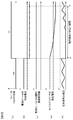
- FIG. 3 is a view showing changes in voltage value and resistance value of each part when the present invention is not applied.
- 3A shows the switching state of the relays 150 and 151
- FIG. 3B shows the ground potential of the battery module 112
- FIG. 3C shows the insulation resistance value between the battery module 112 and the ground potential.
- d) shows the voltage across the coupling capacitor 220
- (e) shows the voltage of the response signal detected by the ground fault detection unit 221.
- the ground potential of the battery module 112 changes as shown in FIG. 3B.
- the insulation resistance value between the battery module 112 and the ground potential does not change before and after time t0.
- the ground potentials of drive circuit 113 and motor 140 are lower than the ground potential of battery module 112 and monitoring device (HV side) 110 before time t0, and therefore the battery module 112 is grounded at time t0.
- An example is shown in the case where the potential is decreasing.
- the ground fault detection unit 221 can not perform ground fault detection.
- the response signal is output correctly again, and ground fault detection can be resumed.
- the period in which the ground fault can not be detected in the ground fault detection unit 221 when the present invention is not applied is a period from time t0 to time t1 shown in FIG.
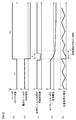
- FIG. 4 is a view showing changes in voltage value and resistance value of each part when the present invention is applied.
- 4A shows the switching state of the relays 150 and 151
- FIG. 4B shows the ground potential of the battery module 112
- FIG. 4C shows the insulation between the battery module 112 and the ground potential.
- the resistance value is shown, (d) shows the voltage across the coupling capacitor 220, and (e) shows the voltage of the response signal detected by the ground fault detection unit 221.
- the positive electrode connection line 160 is connected to the ground potential via the resistor 252, and the insulation of the positive electrode connection line 160 is isolated.
- the resistor 252 acts as a resistor.
- the insulation resistance value between the battery module 112 and the ground potential decreases.
- discharge of coupling capacitor 220 is started accordingly.
- the discharge of the coupling capacitor 220 at this time is performed via the resistor 252 instead of the insulating resistor 202 and the insulating resistor 212 unlike the case of FIG. Therefore, as shown in FIG. 4 (d), the voltage across the coupling capacitor 220 decreases more quickly than in FIG. 3 (d), and becomes substantially constant at time t2.
- the period in which the ground fault can not be detected in the ground fault detection unit 221 is the period from time t0 to time t2 shown in FIG. 4 (e), which is shown in FIG. 3 (e). It can be seen that the period is shorter than the period from time t0 to time t1 when the ground fault can not be detected.
- the start point of the period in which the switch 251 is turned on in the insulation resistance change unit 250 is at a time before time t0 when the relays 150 and 151 are switched from off to on or at the same time as time t0.
- the time T shown in FIG. 4C represents the time from time t0 to the end point of this period, which preferably satisfies the following equation (1).
- C is the capacitance value of the coupling capacitor 220
- Rq is the resistance value of the resistor 252
- VL is the amplitude of the AC signal generated from the AC signal generator 222
- VH is the maximum that the battery module 112 can take.
- Each represents a voltage.
- ln ⁇ VH / (VH-VL) ⁇ represents the natural logarithm of VH / (VH-VL).
- the ground resistance detection device 121 reduces the insulation resistance of the positive electrode connection line 160 when the potential of the positive electrode connection line 160 changes due to the insulation resistance change unit 250. Since this is done, potential fluctuation occurs in the connection line between the battery and the load and ground detection can be resumed quickly after ground detection is stopped.
- the insulation resistance change unit 250 includes a resistor 252 whose one end is grounded, and a switch 251 connected between the resistor 252 and the positive electrode connection line 160. By switching the switch 251 from the disconnected state to the conductive state, the insulation resistance of the positive electrode connection line 160 is reduced, so that the insulation resistance can be reliably reduced with a simple circuit.
- the positive electrode connection line 160 is connected to relays 150 and 151 that disconnect or conduct between the battery module 112 and the drive circuit 113 as a load and the motor 140 according to switching control from the outside.
- the insulation resistance change unit 250 switches the switch 251 from the disconnection state to the conduction state when the relays 150 and 151 electrically connect the battery module 112 and the load. Since it did in this way, when an electric potential change arises in the positive electrode connecting line 160, the insulation resistance of the positive electrode connecting line 160 can be reduced reliably.
- the insulation resistance changing unit 250 may lower the insulation resistance of the positive electrode connection line 160 for the time T represented by the above-mentioned equation (1) after the battery module 112 and the load are electrically connected. preferable. In this way, the insulation resistance of the positive electrode connection line 160 can be reliably reduced until the coupling capacitor 220 is charged or discharged and the voltage across the coupling capacitor 220 becomes constant.
- the ground fault detection device 121 is connected to the positive electrode side of the battery module 112, and the alternating current signal from the alternating current signal generation unit 222 is applied to the positive electrode connection line 160.
- the ground fault detection device 121 may be connected to the negative electrode side of the battery module 112, and the AC signal from the AC signal generator 222 may be applied to the negative electrode connection line 161.
- the ground fault detection is performed by the same method as the above embodiment, and the insulation resistance is lowered in the case of the potential fluctuation of the negative electrode connection line 161 to shorten the period when the ground fault can not be detected. it can.
- Reference Signs List 100 monitoring device 112 battery module 113 drive circuit 114 grounding circuit 120 integrated circuit for battery state monitoring 121 ground fault detection device 130 communication circuit 131 control unit 132 communication unit 140 motor 150 relay 151 relay 160 positive electrode connecting line 161 negative electrode connecting line 201 floating Capacitance 202 insulation resistance 211 stray capacity 212 insulation resistance 220 coupling capacitor 221 ground fault detection unit 222 AC signal generation unit 250 insulation resistance change unit 251 switch 252 resistor
Landscapes
- Engineering & Computer Science (AREA)
- Life Sciences & Earth Sciences (AREA)
- Sustainable Development (AREA)
- Sustainable Energy (AREA)
- Power Engineering (AREA)
- Transportation (AREA)
- Mechanical Engineering (AREA)
- Physics & Mathematics (AREA)
- General Physics & Mathematics (AREA)
- Testing Of Short-Circuits, Discontinuities, Leakage, Or Incorrect Line Connections (AREA)
- Electric Propulsion And Braking For Vehicles (AREA)
Applications Claiming Priority (2)
| Application Number | Priority Date | Filing Date | Title |
|---|---|---|---|
| JP2012284868A JP5926677B2 (ja) | 2012-12-27 | 2012-12-27 | 地絡検知装置 |
| JP2012-284868 | 2012-12-27 |
Publications (1)
| Publication Number | Publication Date |
|---|---|
| WO2014103613A1 true WO2014103613A1 (ja) | 2014-07-03 |
Family
ID=51020707
Family Applications (1)
| Application Number | Title | Priority Date | Filing Date |
|---|---|---|---|
| PCT/JP2013/082123 Ceased WO2014103613A1 (ja) | 2012-12-27 | 2013-11-29 | 地絡検知装置 |
Country Status (2)
| Country | Link |
|---|---|
| JP (1) | JP5926677B2 (enExample) |
| WO (1) | WO2014103613A1 (enExample) |
Cited By (7)
| Publication number | Priority date | Publication date | Assignee | Title |
|---|---|---|---|---|
| CN104865506A (zh) * | 2015-05-20 | 2015-08-26 | 王运国 | 一种直流电气系统的绝缘检测装置 |
| CN106932682A (zh) * | 2017-03-23 | 2017-07-07 | 中国南方电网有限责任公司超高压输电公司南宁局 | 一种电压全站一点接地的接地回路检测方法 |
| JP2017173231A (ja) * | 2016-03-25 | 2017-09-28 | トヨタ自動車株式会社 | 絶縁抵抗低下検出装置 |
| CN110154765A (zh) * | 2019-05-31 | 2019-08-23 | 吉林大学 | 一种串联混合动力车辆高压上下电控制策略 |
| CN113009302A (zh) * | 2021-03-18 | 2021-06-22 | 奇瑞新能源汽车股份有限公司 | 定位电动汽车高压系统绝缘故障的方法及装置 |
| CN115825579A (zh) * | 2022-12-13 | 2023-03-21 | 上海艾为电子技术股份有限公司 | 电容检测电路、芯片、方法及电子设备 |
| WO2024066004A1 (zh) * | 2022-09-26 | 2024-04-04 | 内蒙古霍煤鸿骏铝电有限责任公司 | 一种铝电解槽对地绝缘故障的检测方法 |
Families Citing this family (6)
| Publication number | Priority date | Publication date | Assignee | Title |
|---|---|---|---|---|
| JP7020952B2 (ja) * | 2018-02-13 | 2022-02-16 | 本田技研工業株式会社 | 電源システム |
| CN108196176B (zh) * | 2018-03-01 | 2020-12-15 | 威马智慧出行科技(上海)有限公司 | 一种电池包的绝缘检测报警装置及其方法 |
| CN110531210B (zh) * | 2019-09-24 | 2024-08-23 | 成都凯迪飞研科技有限责任公司 | 航空线束导通与绝缘智能检测系统 |
| US11637421B2 (en) * | 2021-07-09 | 2023-04-25 | Transportation Ip Holdings, Llc | Ground impedance and fault detection system and method |
| US12337703B2 (en) | 2021-07-09 | 2025-06-24 | Transportation Ip Holdings, Llc | Ground impedance and fault detection system and method |
| JP2023040980A (ja) * | 2021-09-10 | 2023-03-23 | 甲神電機株式会社 | 地絡検出装置 |
Citations (3)
| Publication number | Priority date | Publication date | Assignee | Title |
|---|---|---|---|---|
| JP2006170714A (ja) * | 2004-12-14 | 2006-06-29 | Nissan Motor Co Ltd | 地絡検出装置、地絡検出装置の閾値設定方法 |
| JP2010181368A (ja) * | 2009-02-09 | 2010-08-19 | Mitsubishi Motors Corp | バッテリパックの検査装置 |
| JP2012168070A (ja) * | 2011-02-16 | 2012-09-06 | Omron Automotive Electronics Co Ltd | 漏電検知装置、漏電検知装置における閾値等の設定方法 |
-
2012
- 2012-12-27 JP JP2012284868A patent/JP5926677B2/ja active Active
-
2013
- 2013-11-29 WO PCT/JP2013/082123 patent/WO2014103613A1/ja not_active Ceased
Patent Citations (3)
| Publication number | Priority date | Publication date | Assignee | Title |
|---|---|---|---|---|
| JP2006170714A (ja) * | 2004-12-14 | 2006-06-29 | Nissan Motor Co Ltd | 地絡検出装置、地絡検出装置の閾値設定方法 |
| JP2010181368A (ja) * | 2009-02-09 | 2010-08-19 | Mitsubishi Motors Corp | バッテリパックの検査装置 |
| JP2012168070A (ja) * | 2011-02-16 | 2012-09-06 | Omron Automotive Electronics Co Ltd | 漏電検知装置、漏電検知装置における閾値等の設定方法 |
Cited By (9)
| Publication number | Priority date | Publication date | Assignee | Title |
|---|---|---|---|---|
| CN104865506A (zh) * | 2015-05-20 | 2015-08-26 | 王运国 | 一种直流电气系统的绝缘检测装置 |
| JP2017173231A (ja) * | 2016-03-25 | 2017-09-28 | トヨタ自動車株式会社 | 絶縁抵抗低下検出装置 |
| CN106932682A (zh) * | 2017-03-23 | 2017-07-07 | 中国南方电网有限责任公司超高压输电公司南宁局 | 一种电压全站一点接地的接地回路检测方法 |
| CN106932682B (zh) * | 2017-03-23 | 2023-09-29 | 中国南方电网有限责任公司超高压输电公司南宁局 | 一种电压全站一点接地的接地回路检测方法 |
| CN110154765A (zh) * | 2019-05-31 | 2019-08-23 | 吉林大学 | 一种串联混合动力车辆高压上下电控制策略 |
| CN113009302A (zh) * | 2021-03-18 | 2021-06-22 | 奇瑞新能源汽车股份有限公司 | 定位电动汽车高压系统绝缘故障的方法及装置 |
| CN113009302B (zh) * | 2021-03-18 | 2023-03-21 | 奇瑞新能源汽车股份有限公司 | 定位电动汽车高压系统绝缘故障的方法及装置 |
| WO2024066004A1 (zh) * | 2022-09-26 | 2024-04-04 | 内蒙古霍煤鸿骏铝电有限责任公司 | 一种铝电解槽对地绝缘故障的检测方法 |
| CN115825579A (zh) * | 2022-12-13 | 2023-03-21 | 上海艾为电子技术股份有限公司 | 电容检测电路、芯片、方法及电子设备 |
Also Published As
| Publication number | Publication date |
|---|---|
| JP5926677B2 (ja) | 2016-05-25 |
| JP2014126510A (ja) | 2014-07-07 |
Similar Documents
| Publication | Publication Date | Title |
|---|---|---|
| JP5926677B2 (ja) | 地絡検知装置 | |
| CN103718449B (zh) | 电力转换装置 | |
| JP6633585B2 (ja) | 地絡検出装置 | |
| CN101677144B (zh) | 包括超电容器的自治系统中电池的脉冲充电的方法 | |
| CN109642919B (zh) | 接地检测装置以及蓄电系统 | |
| EP2308714A2 (en) | Power supply device and method for making decision as to contactor weld of power supply device | |
| CN106353692B (zh) | 用于在电气系统中检测存在漏电和/或继电器短路情况的监视系统 | |
| JP2014038023A (ja) | 地絡検出回路、電源装置 | |
| CN107228981B (zh) | 劣化指定装置和劣化指定方法 | |
| KR20140041621A (ko) | 절연물의 결함을 검출하는 디바이스 | |
| JP7438213B2 (ja) | 漏電検出装置、車両用電源システム | |
| JP2013205257A (ja) | 電源装置、及びこの電源装置を備える車両並びに蓄電装置 | |
| JP2019056626A (ja) | 地絡検出装置 | |
| CN114144687B (zh) | 漏电检测装置、车辆用电源系统 | |
| JP2013061163A (ja) | 漏電検知装置 | |
| CN103852699A (zh) | 绝缘检测电路及其方法 | |
| CN110914098B (zh) | 借助放电电路对车辆的高压中间电路放电的方法和设备 | |
| CN114788122B (zh) | 车辆用电源装置 | |
| JP2014098681A (ja) | 漏電検知装置 | |
| CN115335715A (zh) | 漏电检测装置、车辆用电源系统 | |
| JP6742191B2 (ja) | 固着検出装置および電池システム | |
| JP7458397B2 (ja) | 漏電検出装置、車両用電源システム | |
| CN113541496B (zh) | 电力转换装置 | |
| JP6607161B2 (ja) | 車載電池システムの制御方法 | |
| KR20160076825A (ko) | 돌입전류 방지 및 배터리 고장 진단이 가능한 배터리 충전 방법 |
Legal Events
| Date | Code | Title | Description |
|---|---|---|---|
| 121 | Ep: the epo has been informed by wipo that ep was designated in this application |
Ref document number: 13867705 Country of ref document: EP Kind code of ref document: A1 |
|
| NENP | Non-entry into the national phase |
Ref country code: DE |
|
| 122 | Ep: pct application non-entry in european phase |
Ref document number: 13867705 Country of ref document: EP Kind code of ref document: A1 |