WO2014103308A1 - 制御方法 - Google Patents
制御方法 Download PDFInfo
- Publication number
- WO2014103308A1 WO2014103308A1 PCT/JP2013/007594 JP2013007594W WO2014103308A1 WO 2014103308 A1 WO2014103308 A1 WO 2014103308A1 JP 2013007594 W JP2013007594 W JP 2013007594W WO 2014103308 A1 WO2014103308 A1 WO 2014103308A1
- Authority
- WO
- WIPO (PCT)
- Prior art keywords
- network
- control
- information terminal
- icon
- communication
- Prior art date
- Legal status (The legal status is an assumption and is not a legal conclusion. Google has not performed a legal analysis and makes no representation as to the accuracy of the status listed.)
- Ceased
Links
Images







Classifications
-
- G—PHYSICS
- G06—COMPUTING OR CALCULATING; COUNTING
- G06F—ELECTRIC DIGITAL DATA PROCESSING
- G06F3/00—Input arrangements for transferring data to be processed into a form capable of being handled by the computer; Output arrangements for transferring data from processing unit to output unit, e.g. interface arrangements
- G06F3/01—Input arrangements or combined input and output arrangements for interaction between user and computer
- G06F3/048—Interaction techniques based on graphical user interfaces [GUI]
- G06F3/0481—Interaction techniques based on graphical user interfaces [GUI] based on specific properties of the displayed interaction object or a metaphor-based environment, e.g. interaction with desktop elements like windows or icons, or assisted by a cursor's changing behaviour or appearance
- G06F3/0482—Interaction with lists of selectable items, e.g. menus
-
- G—PHYSICS
- G08—SIGNALLING
- G08C—TRANSMISSION SYSTEMS FOR MEASURED VALUES, CONTROL OR SIMILAR SIGNALS
- G08C17/00—Arrangements for transmitting signals characterised by the use of a wireless electrical link
- G08C17/02—Arrangements for transmitting signals characterised by the use of a wireless electrical link using a radio link
-
- G—PHYSICS
- G06—COMPUTING OR CALCULATING; COUNTING
- G06F—ELECTRIC DIGITAL DATA PROCESSING
- G06F3/00—Input arrangements for transferring data to be processed into a form capable of being handled by the computer; Output arrangements for transferring data from processing unit to output unit, e.g. interface arrangements
- G06F3/01—Input arrangements or combined input and output arrangements for interaction between user and computer
- G06F3/048—Interaction techniques based on graphical user interfaces [GUI]
- G06F3/0481—Interaction techniques based on graphical user interfaces [GUI] based on specific properties of the displayed interaction object or a metaphor-based environment, e.g. interaction with desktop elements like windows or icons, or assisted by a cursor's changing behaviour or appearance
- G06F3/04817—Interaction techniques based on graphical user interfaces [GUI] based on specific properties of the displayed interaction object or a metaphor-based environment, e.g. interaction with desktop elements like windows or icons, or assisted by a cursor's changing behaviour or appearance using icons
-
- G—PHYSICS
- G06—COMPUTING OR CALCULATING; COUNTING
- G06F—ELECTRIC DIGITAL DATA PROCESSING
- G06F3/00—Input arrangements for transferring data to be processed into a form capable of being handled by the computer; Output arrangements for transferring data from processing unit to output unit, e.g. interface arrangements
- G06F3/01—Input arrangements or combined input and output arrangements for interaction between user and computer
- G06F3/048—Interaction techniques based on graphical user interfaces [GUI]
- G06F3/0484—Interaction techniques based on graphical user interfaces [GUI] for the control of specific functions or operations, e.g. selecting or manipulating an object, an image or a displayed text element, setting a parameter value or selecting a range
- G06F3/04842—Selection of displayed objects or displayed text elements
-
- H—ELECTRICITY
- H04—ELECTRIC COMMUNICATION TECHNIQUE
- H04L—TRANSMISSION OF DIGITAL INFORMATION, e.g. TELEGRAPHIC COMMUNICATION
- H04L63/00—Network architectures or network communication protocols for network security
- H04L63/12—Applying verification of the received information
- H04L63/126—Applying verification of the received information the source of the received data
-
- G—PHYSICS
- G08—SIGNALLING
- G08C—TRANSMISSION SYSTEMS FOR MEASURED VALUES, CONTROL OR SIMILAR SIGNALS
- G08C2201/00—Transmission systems of control signals via wireless link
- G08C2201/30—User interface
-
- G—PHYSICS
- G08—SIGNALLING
- G08C—TRANSMISSION SYSTEMS FOR MEASURED VALUES, CONTROL OR SIMILAR SIGNALS
- G08C2201/00—Transmission systems of control signals via wireless link
- G08C2201/30—User interface
- G08C2201/34—Context aware guidance
-
- G—PHYSICS
- G08—SIGNALLING
- G08C—TRANSMISSION SYSTEMS FOR MEASURED VALUES, CONTROL OR SIMILAR SIGNALS
- G08C2201/00—Transmission systems of control signals via wireless link
- G08C2201/40—Remote control systems using repeaters, converters, gateways
- G08C2201/42—Transmitting or receiving remote control signals via a network
Definitions
- the present invention relates to a control method in a remote control system.
- Patent Document 1 discloses a technology related to an integrated controller that can comfortably control devices including home appliances.
- Patent Document 1 has a problem that the home appliance can be controlled from outside the house even when the home appliance handles fire.
- the present invention has been made in view of the above-described circumstances, and an object thereof is to provide a control method capable of appropriately controlling a control target device according to a situation using an information terminal.
- a control method includes a plurality of devices and an information terminal that controls a control target device that is at least one of the plurality of devices via a network.
- a control method in a remote control system comprising: a step of determining whether or not communication using the network is secure and the communication using the network; and for each of the plurality of devices Displaying an icon for displaying a control menu corresponding to the device in a user interface area in the display unit of the information terminal in a display mode determined according to the determined safety of the communication, and the information A control menu for controlling a device corresponding to the selected icon in the user interface area of the terminal. And generating a control signal for causing the control target device to execute control corresponding to the first control menu when the first control menu is selected from the control menu displayed on the information terminal. And transmitting the control signal to the device to be controlled through the network.
- the control method of the present invention can appropriately control the device to be controlled according to the safety of communication established by the information terminal.
- FIG. 1 is a diagram illustrating an example of the overall configuration of a remote control system according to an embodiment.
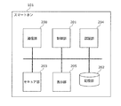
- FIG. 2 is a block diagram illustrating an example of a configuration of the information terminal in the embodiment.
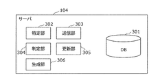
- FIG. 3 is a block diagram illustrating an example of a configuration of the server in the embodiment.
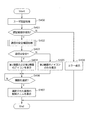
- FIG. 4 is a flowchart showing the operation of the remote control system in the embodiment.
- FIG. 5 is a flowchart showing a communication confirmation process of the remote control system in the embodiment.
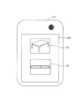
- FIG. 6 is a diagram illustrating an example of an operation screen of the information terminal in the remote control system according to the embodiment.
- FIG. 7 is a diagram illustrating an example of an operation screen of the information terminal in the remote control system according to the embodiment.
- FIG. 1 is a diagram illustrating an example of the overall configuration of a remote control system according to an embodiment.
- FIG. 2 is a block diagram illustrating an example of a configuration of the information terminal in the embodiment.
- FIG. 3 is a block diagram illustrating
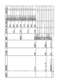
- FIG. 8 is a diagram illustrating an operation condition when the control target device is operated with the remote control application registered in the DB according to the embodiment.
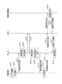
- FIG. 9 is a timing chart showing an example of processing of the remote control system in the example of the embodiment.
- FIG. 10 is a diagram illustrating an example of a GUI of a display screen of a smartphone in an example of the embodiment.
- FIG. 11 is a table showing the contents of information transmitted to the server by the remote control application in the example of the embodiment.
- FIG. 12 is a diagram illustrating an example of a user information table registered in the DB of the server in the example of the embodiment.
- FIG. 13 is a diagram illustrating an example of a device information table registered in the server DB in the example of the embodiment.
- FIG. 14A is a diagram illustrating an example of a smart phone display screen in an example of the embodiment.
- FIG. 14B is a diagram illustrating an example of a smart phone display screen in an example of the embodiment.
- Patent Document 1 Korean that became the basis of the invention
- a control target device (hereinafter also referred to as a target device) that is a home appliance to be controlled among a plurality of home appliances is “operator (who)”, “operation time (when)”. ”,“ Location where to operate ”,“ Operation target device (what) ”,“ Location where the target device is located (to where) ”, etc.
- the control menu is different.
- the present invention has been made in view of the above-described circumstances, and an object thereof is to provide a control method capable of appropriately controlling a control target device according to a situation using an information terminal.
- a control method includes a plurality of devices and an information terminal that controls a control target device that is at least one of the plurality of devices via a network.
- a control method in a remote control system comprising: a step of determining whether or not communication using the network is secure and the communication using the network; and for each of the plurality of devices Displaying an icon for displaying a control menu corresponding to the device in a user interface area in the display unit of the information terminal in a display mode determined according to the determined safety of the communication, and the information A control menu for controlling a device corresponding to the selected icon in the user interface area of the terminal. And generating a control signal for causing the control target device to execute control corresponding to the first control menu when the first control menu is selected from the control menu displayed on the information terminal. And transmitting the control signal to the device to be controlled through the network.
- the device when the device is a device that handles fire, when the network to which the information terminal is connected is the first network, the reliability is higher than that of the first network.
- the icon corresponding to the device may be determined to have a different display mode when the second network is low.
- the icon corresponding to the device cannot be selected. It may be displayed in various display modes.
- the first network may be a network provided for a fee
- the second network may be a network provided free of charge
- the information terminal is connected to the device depending on whether the communication is established using a hardware security module.
- the corresponding icon may be determined in a different display mode.
- the device in the step of displaying the icon, if the device is a device that handles fire and the information terminal establishes the communication without using a hardware security module, the device corresponds to the device.
- the icon to be displayed may be displayed in a display mode that cannot be selected.
- the method further includes a step of determining whether or not an operator operating the information terminal is a predetermined operator stored in advance, and in the step of displaying the icon, the operator When it is determined that the operator is the predetermined operator, a plurality of the icons corresponding to the plurality of devices are displayed in the user interface area, and when the operator is determined not to be the predetermined operator, An error display may be displayed in the user interface area.
- FIG. 1 is a diagram illustrating an example of the overall configuration of a remote control system according to an embodiment.
- the remote control system 100 includes information terminals 101 and 102 such as smart phones, a network 103, a server 104, and a home network 105.
- a home gateway hereinafter referred to as HGW 105a
- a plurality of devices such as a first device 105b and a second device 105c are installed.
- the first device 105b is, for example, a kotatsu
- the second device 105c is, for example, a BD (Blu-ray (registered trademark) Disc) recorder.
- the control target device can communicate with the server 104 by connecting to the network 103 via the HGW 105a.
- the HGW 105 a has a function of notifying a processing request from the server 104 to the control target device and also notifying the server 104 of information and processing results acquired from the control target device.
- the network 103 includes the Internet 103c.
- the information terminals 101 and 102 are connected to the Internet 103c via, for example, a first network 103a or a second network 103b included in the network 103.
- the first network 103a is a network provided for a fee such as 3G, LTE, WiMAX, AXGP, or the like.
- the second network 103b is a network provided free of charge, such as a public wireless LAN.
- FIG. 2 is a block diagram illustrating an example of the configuration of the information terminal in the embodiment.
- the information terminal 101 has a function as a remote controller that issues a processing request to a control target device.
- the function of the information terminal 101 as a remote controller is realized by starting a remote control application installed in the information terminal 101 in advance.
- the information terminal 101 includes a communication unit 200, a control unit 201, a storage unit 202, a secure unit 203, an authentication unit 204, and a display unit 205.
- the communication unit 200 establishes wireless communication with the network 103 by connecting to the first network 103a or the second network 103b.
- the storage unit 202 stores a remote control application program.
- the control unit 201 implements a remote control function in the information terminal 101 by executing a remote control application program stored in the storage unit 202.
- the display unit 205 is a touch display or the like, and has at least a user interface area where touch input is possible.
- the display unit 205 is controlled by the control unit 201. That is, the display unit 205 displays a control menu, icons, and the like in the display mode determined by the control unit 201 on the display screen including the user interface area.
- the icon is an image indicating each of a plurality of devices, and if selected when displayed in a selectable state, the icon transitions to a control menu screen for controlling the device. That is, the icon is a user interface that can accept input from the user.
- the communication unit 200 transmits a control signal to the control target device via the network 103.
- the secure unit 203 stores an encryption key for performing certificate encryption, authentication, digital signature, and the like when performing communication using the communication unit 200.
- a hardware security module such as a security chip It is.
- Authentication unit 204 authenticates a user who uses the remote control application.
- the authentication unit 204 identifies a user who is operating the information terminal 101 by, for example, fingerprint authentication, personal authentication by image recognition, speaker authentication by voice, or the like. More specifically, the authentication unit 204 acquires the user's fingerprint, the user's face image, or the user's voice from the user, so that the user's fingerprint, the user's face image, or the user stored in advance is acquired.
- the user is identified by collating the authentication data in which the voice and the user ID are associated with each other and identifying the matched fingerprint, facial image, or user ID associated with the voice.
- the control unit 201 determines whether the communication performed by the communication unit 200 of the information terminal 101 and the communication using the network 103 is safe.
- the control unit 201 displays a control menu corresponding to the device in the user interface area of the display unit 205 of the information terminal 101 in a display mode determined according to the determined communication safety for each of the plurality of devices. Display the icon.
- the control unit 201 causes the control target device to execute control corresponding to the first control menu. Control signal is generated.
- the control unit 201 has lower reliability than the first network 103a when the network 103 to which the information terminal 101 is connected is the first network 103a.
- the icon corresponding to the device may be determined in a different display mode when it is the second network 103b.
- the control unit 201 has a display form in which an icon corresponding to the crisis cannot be selected. It may be displayed.
- the control unit 201 moves the network 103 from the second network 103b to the first network 103b.
- a dialog for confirming whether or not to switch to the network 103a may be displayed.
- the communication unit 200 starts from the second network 103b. It may be switched to the first network 103a.
- the control unit 201 changes the icon corresponding to the device depending on whether the information terminal 101 has established communication using the hardware security module.
- the display mode may be determined.
- the control unit 201 cannot select an icon corresponding to the device. It may be displayed in a display form.
- control unit 201 is a device that handles fire, and the communication unit 200 of the information terminal 101 has established communication without using the secure unit 203 (hardware security module).
- the icon corresponding to the device may be displayed in a display mode that cannot be selected.
- the authentication unit 204 may determine whether or not the operator operating the information terminal 101 is a predetermined operator barrel stored in advance. Then, when the authentication unit 204 determines that the operator is a predetermined operator, the control unit 201 may display a plurality of icons corresponding to a plurality of devices in the user interface area of the display unit 205. Further, when the authentication unit 204 determines that the operator is not a predetermined operator, the control unit 201 may display an error display in the user interface area of the display unit 205.
- FIG. 3 is a block diagram illustrating an example of the configuration of the server in the embodiment.
- the server 104 receives a processing request from the information terminal 101, for example, and executes the processing request. Further, the server 104 performs processing for inquiring the HGW 105a for information necessary for executing the processing request. The server 104 notifies the process target to the control target device via the HGW 105a.
- the server 104 includes a database (DB 301), a specifying unit 302, a transmitting unit 303, a determining unit 304, an updating unit 305, and a generating unit 306.
- Registered in the DB 301 are the type and device ID of each control target device, the function of the device, and information regarding the owner (individual / shared) who owns the device. Since the control target devices have different functions (functions that can be provided), the registered information is different.
- the functions of the kotatsu include power on and power off
- the functions of the BD recorder include power on, power off, playback, fast forward, recording, and reservation.
- the DB 301 stores the types and device IDs of the devices to be controlled as shown in FIG. 8, security conditions necessary for the operation of the devices (operator authentication, reliability restrictions on the communication network, hardware Information on tamper resistance) is registered.
- FIG. 8 is a diagram illustrating an operation condition when operating the control target device with the remote control application registered in the DB 301.
- the operation conditions in FIG. 8 indicate the following.
- the operating condition is a device that handles fire such as kotatsu, the operator is authenticated, the reliability of the established communication network is high, and there is tamper resistance by hardware (that is, the hardware security module)
- the operation condition is that the operation of the function of a device such as a BD recorder that does not handle fire is highly reliable if the operator is authenticated, and the tamper resistance by hardware is high. This indicates that the device can be operated by the remote control application of the information terminal 101 regardless of whether or not there is a possibility.
- the identifying unit 302 identifies the owner (operator) of the information terminal 101 (smart phone) that issued the processing request based on the device ID.
- the determination unit 304 determines whether the information terminal 101 (smart phone) that issued the processing request exists in the house based on the current position information of the operator and the home position information of the operator registered in advance. To determine if it exists.
- the transmission unit 303 controls the information terminal 101 by transmitting an interface according to the identified owner (operator) attribute, the current position of the information terminal 101 (smartphone), the attribute of the control target device, the function, and the like.
- An interface corresponding to the situation can be provided to the unit 201.
- FIG. 4 is a flowchart showing the operation of the remote control system in the embodiment.
- FIG. 5 is a flowchart showing the confirmation process of the remote control system in the embodiment.
- 6 and 7 are diagrams showing an example of a smart phone operation screen in the remote control system according to the present embodiment.
- the information terminal 101 is a terminal having a function of remotely controlling the first device 105b and the second device 105c in the home network 105.
- the function as a remote controller in the information terminal 101 is provided by a remote control application installed in the information terminal 101.
- the user starts a remote control application on the information terminal 101.
- the remote control application determines whether the user who started the remote control application has control authority over the information terminal 101 (authentication process) (S400).
- the authentication unit 204 displays an authentication screen 601 for performing authentication by fingerprint on the display unit 205 of the information terminal 101 as shown in FIG. For example, an instruction prompting the reader 400 to hold the index finger is displayed.
- the authentication unit 204 performs an authentication process by determining whether or not the fingerprint registered by the user in advance matches the fingerprint acquired by the fingerprint authentication reader 400.
- the authentication unit 204 determines that the fingerprint registered in advance by the user matches the fingerprint acquired by the fingerprint authentication reader 400, authentication by fingerprint authentication has succeeded (the user has control authority over the information terminal 101). Otherwise, it is determined that authentication by fingerprint authentication has failed (the user does not have control authority over the information terminal 101).
- control unit 201 determines whether or not the authentication process by fingerprint authentication is successful (S401).
- the remote control application (control unit 201) gives the user permission to use the information terminal 101, and whether or not the communication using the established network 103 is safe. A confirmation process is performed to confirm whether or not (S402).
- the control unit 201 confirms communication using the network established by the information terminal 101 (S500). Specifically, when the information terminal 101 is connected to the first network 103a which is a pay communication network such as a mobile phone line contracted with a communication company, the control unit 201 establishes the information terminal 101 It is determined that the existing communication is a highly reliable communication network (permitted network). In addition, when the information terminal 101 is connected to the second network 103b which is a communication network provided free of charge such as a public wireless LAN, the control unit 201 is a communication network (non-permitted network) with low reliability. to decide.
- the first network 103a which is a pay communication network such as a mobile phone line contracted with a communication company
- the control unit 201 establishes the information terminal 101 It is determined that the existing communication is a highly reliable communication network (permitted network).
- the control unit 201 is a communication network (non-permitted network) with low reliability. to decide.
- control unit 201 determines whether or not the network established by the information terminal 101 is a permitted network (S501).
- control unit 201 determines that the network is a permitted network (S501: Y), it checks the security of the information terminal 101 (S502). That is, the remote control application (control unit 201) checks whether or not the information terminal 101 is a security compatible terminal. Specifically, if the remote control application (control unit 201) determines that the network 103 established by the information terminal 101 is a highly reliable communication network (S501: Y), the remote control application (control unit 201) is for operating the control target device. Establish communication. At that time, the communication unit 200 performs secure communication using, for example, SSL (Secure Socket Layer) so that information can be transmitted and received after encryption. At this time, key information used for encryption is recorded in the secure unit 203 inside the smartphone.
- SSL Secure Socket Layer
- the remote control application (control unit 201) checks whether or not the information terminal 101 has the secure unit 203. That is, the control unit 201 determines whether or not the information terminal 101 has established communication using the hardware security module.
- control unit 201 determines whether or not the information terminal 101 is a security compatible terminal (S503).
- control unit 201 When it is determined that the control unit 201 is an information terminal in which the secure unit 203 is mounted on the information terminal 101 being used (that is, a security-compatible terminal) (S503: Y), the information terminal 101 is established. It is determined that the communication is safe (S504). That is, when step S503 is Y, the control unit 201 determines that the communication established by the information terminal 101 is a highly reliable communication network, and the key information is protected by hardware. Since the determination is made, it is determined that the communication established by the information terminal 101 is safe, and the confirmation process is terminated.
- control unit 201 determines in step S501 that the network 103 established by the information terminal 101 is not a permitted network (S501: N), or the secure unit 203 is mounted on the information terminal 101 being used. If it is determined that the terminal is not an information terminal (that is, a terminal that does not support security) (S503: N), it is determined that the communication established by the information terminal 101 is not safe (S505), and the confirmation process is terminated.
- control unit 201 determines whether the communication established by the information terminal 101 is safe (S403).
- the control unit 201 determines that the communication established by the information terminal 101 is safe (S403: Y), all of the first device 105b (kotatsu) and the second device 105c (BD recorder) In order to satisfy the operation condition (see FIG. 8), icons indicating the first device 105b and the second device 105c are displayed in a selectable display mode in the user interface area of the display unit 205 (S404). That is, when the encryption key information is protected by hardware and highly reliable communication is established, the remote control application displays both icons of the first device 105b and the second device 105c in a selectable display mode. (For example, FIG. 10).
- the operation condition for the first device 105b (kotatsu) is not satisfied, and the second device 105c (BD In order to satisfy the operation condition for the recorder, only the icon indicating the second device 105c is displayed in a selectable display mode in the user interface area of the display unit 205 (S405).
- control unit 201 determines whether a selectable icon is selected by being tapped by the user (S406).
- a control menu for operating the first device 105b is displayed (S407).
- a control menu for operating the second device 105c is displayed (S407).
- the control unit 201 does not perform any processing because the icon 701 is not displayed in a selectable state.
- step S401 when authentication fails in step S401 (S401: N), as shown in FIG. 6B, a remote control application screen 602 for notifying the user that the user has no authority to operate the display unit 205 is displayed ( S408) The process ends.
- FIG. 9 is a timing chart showing an example of processing of the remote control system in the example of the embodiment.
- the function as a remote controller in the smart phone (information terminal 101) will be described as being provided by a remote control application installed in the smart phone, as described above.
- an operator (hereinafter referred to as a user) of a smart phone (information terminal 101) activates a remote control application (S901).
- the remote control application displays a GUI (Graphical User Interface) of the remote control application on the display screen 110 shown in FIG. 10 (S902). That is, here, the remote control application GUI is displayed by performing the processing of steps S400 to S405 shown in FIG. 4 described above.
- GUI Graphic User Interface
- FIG. 10 is a diagram illustrating an example of a display screen of a smart phone in an example of the embodiment.
- a display screen 110 illustrated in FIG. 10 corresponds to the interface area of the display unit 205 and is an area where a user can perform touch input.
- kotatsu and a BD recorder are displayed as icons (icon 52, icon 53) as control target device candidates.
- the user can select the kotatsu as the control target device by tapping (touch input) the kotatsu icon 52.
- the remote control application for example, information as shown in FIG. 11, that is, the ID of the smartphone (information terminal 101), the position information of the smartphone (positioning information by GPS), the kotatsu A processing request for the kotatsu including information such as the device ID is transmitted to the server 104 (S903). It is assumed that the information on the smart phone ID and the control target device ID shown in FIG. 11 is shared between the server 104 and the remote control application in advance.
- FIG. 11 is a table showing the contents of information transmitted to the server by the remote control application in the example of the first embodiment. Note that step S903 is performed by performing step S406 shown in FIG.
- the smart phone position information may include GPS altitude information in addition to GPS positioning information. Positioning by GPS of the position information may be performed periodically, or may be configured to be performed when the remote control application is activated or transmitted to the server 104.
- the positioning of the position information is not limited to the GPS method.
- the position information of a base station of a smart phone may be used, or the current position may be estimated from a movement history using an acceleration sensor included in the smart phone.
- the home entrance lock is locked using a smart phone, it may be determined that the user has gone out of the house. That is, there are various methods for estimating position information (positioning), and any of them may be adopted.
- FIG. 12 is a diagram illustrating an example of a user information table registered in the server DB in the example of the embodiment. That is, when the smart phone ID notified from the remote control application (information terminal 101) is “1”, the specifying unit 302 of the server 104 uses FIG. 12 to indicate that the owner of the smart phone is “dad”. Can be identified as “adult”.
- the server 104 executes a determination process (S905). More specifically, the determination unit 304 of the server 104 determines the smart phone that issued the processing request based on the current position information of the smart phone notified from the smart phone remote control application and the pre-registered home position information. Is in the house or out of the house.
- the determination unit 304 of the server 104 determines that the smartphone is located (exists) in the house when the difference between the current position information and the home position information is within ⁇ 10 m, and is otherwise located outside the house. It is determined that it exists.
- the determination unit 304 of the server 104 may determine that the smart phone is located in the home regardless of the positioning information when the smartphone is connected to the home wireless LAN.
- the determination unit 304 of the server 104 may determine that the smart phone is located outside the home when the positioning information is not obtained or when the positioning information is obtained and the positioning accuracy is low. From the viewpoint of safety etc., if functions that can be operated from outside the house are restricted so that even functions that can be operated from inside the house cannot be operated from outside the house, it is more than This is because it is possible to improve safety if it is determined to be out of the house.
- the determination unit 304 of the server 104 determines in S905 that the smart phone (information terminal 101) that issued the processing request is present (position) in the home.
- the server 104 executes an update process for updating the current state of the control target device (S908). More specifically, based on the control target device ID notified from the smart phone, the update unit 305 of the server 104 communicates with the HGW 105a that detects the state change of the control target device in real time (S906 and In step S907, the current state of the control target device is acquired, and for example, an update process is performed to update the state item (current state of the control target device) in the device information table illustrated in FIG. 13 (S908). In the present embodiment, in S908, as shown in FIG. 13, the item of the kotatsu status of the device ID “1” is “power on”.
- FIG. 13 is a diagram illustrating an example of a device information table registered in the server DB in the example of the embodiment.
- the DB 301 of the server for example, information related to the control target device as shown in FIG. 13 is registered as a device information table.
- the device information table shown in FIG. 13 the device ID, device type, owner, and operable functions are registered in advance.
- the server 104 can acquire the status of the control target device in real time through the exchange with the HGW 105a, the current status of the control target device can be reflected in the status item of the device information table registered in the DB 301. it can.
- the server 104 may inquire the control target device via the HGW 105a every time there is a processing request from the smart phone.
- the server 104 stores the location of the smart phone, the content of the processing request, the state of the control target device, and the like as a plurality of control indexes in the DB 301 as a log. Then, the server 104 may analyze the plurality of control indexes and use them to determine the display mode of the control menu of the control target device and the user interface.
- the server 104 generates display information based on a plurality of control indexes (S909). More specifically, the generation unit 306 of the server 104 uses a plurality of control indices such as user attributes, smart phone positions, and the current state of the kotatsu, and the device information table shown in FIG. Whether the ON button and OFF button are displayed or not is determined. Based on the determination result, the server 104 generates display information indicating the display mode and display content on the display unit 205 to be provided to the control unit 201 of the smartphone.
- the generation unit 306 of the server 104 indicates that the attribute of the smartphone user (owner) is “adult”, the current position of the smartphone is “home”, and the current state of the kotatsu is “power supply” Since it is “ON”, as shown in FIG. 13, it is determined that the ON button as the control menu is “non-display” and the OFF button is “display”.
- the generation unit 306 of the server 104 generates display information based on the determination result. In the present embodiment, the generation of the display information has been described as being executed by the server 104. However, the present invention is not limited to this.
- the server 104 may notify the determination result to the remote control application, and may generate display information based on the determination result notified of the remote control application.
- the server 104 (transmission unit 303) notifies (transmits) the generated display information to the remote control application (S910).
- the remote control application executes a process for performing UI display (S911). More specifically, the smart phone remote control application (control unit 201) determines the content (display content) to be displayed in the user interface area of the display unit 205 and the display mode based on the transmitted display information. Then, the remote control application causes the display unit 205 to display the display content and display mode (display screen 110) determined as shown in FIG. 14A or FIG. 14B, for example.
- FIGS. 14A and 14B are diagrams illustrating an example of a display screen of the smartphone in the example of the embodiment. Note that the processing in step S911 corresponds to the processing in step S407 in FIG.
- the remote control application is determined to be non-displayed in S909 on the display screen 110 displayed on the display unit 205 based on the notified (transmitted) display information, for example, as shown in FIG. 14A.
- the ON button is not displayed as the control menu, and only the OFF button (power off button 521) is displayed as the control menu.
- the remote control application may indicate that the ON button (power-on button 522) determined not to be displayed cannot be selected as a control menu by graying out display.
- the user of the smartphone instructs to execute a process corresponding to the button by tapping (touch input) the button displayed on the display screen 110 (user interface area). Then, the remote control application notifies (transmits) a control signal indicating the execution instruction of the process to the server 104 (S912).
- the control signal is a control signal indicating that the power-off process is executed.
- the server 104 notifies the control target device via the HGW 105a so as to execute the control signal notified from the remote control application (S913, S914).
- the server 104 since the control target device is a kotatsu, the server 104 notifies the kotatsu to execute the power-off process (execution instruction) indicated in the control signal.
- the control target device that has received the control signal executes the process (S915), and notifies the server 104 of the completion of the process via the HGW 105a (S916, S917).
- the kotatsu executes a power-off process, and notifies the server 104 of the completion of the process via the HGW 105a.
- the control target device has been described as receiving a control signal, the present invention is not limited to this. Only a signal requesting execution of the processing may be received based on the control signal by the server. In this case, the control target device may perform the process based on the signal.
- the server 104 receives a notification that the processing is completed from the control target device via the HGW 105a, and performs an update process for updating the current state of the control target device (S918).
- the update unit 305 of the server 104 receives a notification from the kotatsu that the process has been completed via the HGW 105a, and sets the “status” item in the device status table shown in FIG. 13 to “power off”. Update process to update.
- the operation on the control target device is limited. Add. Thereby, for example, even if an unauthorized access due to hacking or the like occurs, it is possible to limit the operation on a device that handles fire such as kotatsu.
- a device operation is limited to a terminal that is not equipped with a hardware security module such as a security chip and cannot protect the encryption key in hardware. .
- a hardware security module such as a security chip
- fingerprint authentication is used for the authentication process.
- the present invention is not limited to this.
- Personal recognition using an image such as a face and speaker recognition using voice are also possible.
- the authentication process used may be used.
- a configuration is displayed in which “cannot be operated” is displayed on the screen.
- the present invention is not limited to this. For example, if authentication fails, In the case of a family member who is not a person, the icon may be grayed out for the device A and the operation may be permitted for the device B.
- an email notifying that authentication has failed may be sent to the smartphone owned by the family at the same time.
- the first network 103a is a paid network (for example, a mobile communication network), and the second network 103b is a free network (for example, a public wireless LAN).
- the present invention is not limited to this, and the first network 103a may be configured via a local network such as a WAN, and the second network 103b may be configured via a global network such as the Internet.
- a communication line when a line with a large number of communication disconnections and a low reliability is used, it may be determined that the network is a low-reliability network that imposes operation restrictions.
- communication networks such as WiFi, WiMAX, LTE, and 3G that have relatively high communication speeds are distinguished from communication networks that use Bluetooth (registered trademark), ZigBee, NFC, and infrared communication that have relatively low communication speeds.
- Bluetooth registered trademark
- ZigBee ZigBee
- NFC infrared communication
- the icon of the first device 105b is not displayed, the device whose operation is restricted may be grayed out, and the operation may not be performed even if the grayed out icon is tapped.
- control unit 201 determines that the network established by the information terminal 101 is not a permitted network in the confirmation processing in step S402 (S501: N), it determines that communication is not secure. (S505) is not limited to this.
- the control unit 201 determines that the network established in the information terminal 101 is not a permitted network (that is, determines that the network is connected to the second network 103b), the permitted unit (that is, the first network 103a).
- the control unit 201 may perform a process of switching from the second network 103b to the first network 103a.
- step S501 after determining whether or not the network established by the information processing terminal 101 is a permitted network (S501), the determination in step S501 is performed. Is “Y”, it is determined whether or not the information terminal 101 is a security-compatible terminal (S503), but this order may be reversed. That is, the control unit 201 may determine that the communication established by the information terminal 101 is not secure only on the condition that the information terminal 101 is not a security-compatible terminal.
- each component may be configured by dedicated hardware or may be realized by executing a software program suitable for each component.
- Each component may be realized by a program execution unit such as a CPU or a processor reading and executing a software program recorded on a recording medium such as a hard disk or a semiconductor memory.
- the present invention can be used for a control method in a controller system, and in particular controls home-integrated remote control UI that can perform remote control for devices with a risk of fire, portable information terminals equipped with a remote control function, and the like. It can also be used for methods.
- Remote control system 101, 102 Information terminal 103 Network 103a First network 103b Second network 103c Internet 104 Server 105 Home network 105a HGW 105b First device 105c Second device 110 Display screen 200 Communication unit 201 Control unit 202 Storage unit 203 Secure unit 204 Authentication unit 205 Display unit 301 DB 302 Identification Unit 303 Transmission Unit 304 Determination Unit 305 Update Unit 306 Generation Unit 400 Fingerprint Authentication Reader 521 Power Off Button 522 Power On Button 601 Authentication Screen 602 Remote Control Application Screens 701 and 702 Icons
Landscapes
- Engineering & Computer Science (AREA)
- General Engineering & Computer Science (AREA)
- Theoretical Computer Science (AREA)
- General Physics & Mathematics (AREA)
- Physics & Mathematics (AREA)
- Human Computer Interaction (AREA)
- Computer Networks & Wireless Communication (AREA)
- Computer Security & Cryptography (AREA)
- Computer Hardware Design (AREA)
- Computing Systems (AREA)
- Signal Processing (AREA)
- Telephonic Communication Services (AREA)
- Selective Calling Equipment (AREA)
Abstract
複数の機器と、ネットワークを介して制御対象機器の制御を行う情報端末とを備えるリモートコントロールシステムにおける制御方法であって、情報端末が行っている通信であって、ネットワークを利用した通信が安全であるか否かを判定するステップと、複数の機器のそれぞれについて、判定された通信の安全性に応じて決定した表示態様で、情報端末の表示部におけるユーザインタフェース領域に当該機器に対応する制御メニュを表示させるためのアイコンを表示させるステップと、情報端末のユーザインタフェース領域に、選択されたアイコンに対応する機器を制御するための制御メニュを表示させるステップと、情報端末に表示された制御メニュのうち第1制御メニュが選択された場合、第1制御メニュに対応する制御を制御対象機器に実行させるための制御信号を生成するステップと、ネットワークを介して制御信号を制御対象機器に送信するステップと、を含む。
Description
本発明は、リモートコントロールシステムにおける制御方法に関する。
近年、家庭内においてもネットワーク環境が整備されてきたことに伴い、パソコンなどの情報機器だけでなく、テレビ、ビデオレコーダ、エアコンおよび冷蔵庫等の家電機器もネットワークに接続されつつある。それによって、ネットワークを介して、家電機器を制御することが可能となるなどユーザに様々な利便性をもたらしつつある。
例えば、特許文献1には、家電機器を含む機器を快適に制御できる統合コントローラに関する技術が開示されている。
しかしながら、特許文献1に開示されるような従来技術では、例えば家電機器が火気を扱うものである場合でも家の外からその家電機器の制御が行えるなどの問題がある。
本発明は、上述の事情を鑑みてなされたもので、情報端末を用いて制御対象機器を状況に応じて適切に制御することができる制御方法を提供することを目的とする。
上記目的を達成するために、本発明の一態様に係る制御方法は、複数の機器と、ネットワークを介して前記複数の機器のうち少なくとも一の機器である制御対象機器の制御を行う情報端末とを備えるリモートコントロールシステムにおける制御方法であって、前記情報端末が行っている通信であって、前記ネットワークを利用した通信が安全であるか否かを判定するステップと、前記複数の機器のそれぞれについて、判定された前記通信の安全性に応じて決定した表示態様で、前記情報端末の表示部におけるユーザインタフェース領域に当該機器に対応する制御メニュを表示させるためのアイコンを表示させるステップと、前記情報端末の前記ユーザインタフェース領域に、選択されたアイコンに対応する機器を制御するための制御メニュを表示させるステップと、前記情報端末に表示された前記制御メニュのうち第1制御メニュが選択された場合、前記第1制御メニュに対応する制御を前記制御対象機器に実行させるための制御信号を生成するステップと、前記ネットワークを介して前記制御信号を前記制御対象機器に送信するステップと、を含む。
なお、これらの全般的または具体的な態様は、システム、方法、集積回路、コンピュータプログラムまたはコンピュータで読み取り可能なCD-ROMなどの記録媒体で実現されてもよく、システム、方法、集積回路、コンピュータプログラムおよび記録媒体の任意な組み合わせで実現されてもよい。
本発明の制御方法は、情報端末が確立している通信の安全性に応じて、制御対象機器を適切に制御することができる。
(発明の基礎となった知見)
特許文献1に開示されるような従来技術では、例えば家電機器が火気を扱うもの樽場合でも家の外からその家電機器の制御が行えるなどの問題がある。
特許文献1に開示されるような従来技術では、例えば家電機器が火気を扱うもの樽場合でも家の外からその家電機器の制御が行えるなどの問題がある。
より具体的には、複数の家電機器のうち制御対象となる家電機器である制御対象機器(以下、対象機器とも記載)は、「操作をする人(who)」、「操作する時間(when)」、「操作する場所(at where)」、「操作対象機器(what)」および「操作対象機器の置いてある場所(to where)」等の状況によって、提供可能な機能でも制御可能な項目(制御メニュ)が異なる。また、操作性、安全性、プライバシー、コスト(電気代など)、騒音・振動(周りへの迷惑)などの観点から、状況によっては、制御態様機器の特定の制御を抑制する必要も生じると考えられる。例えば家の外では家の中の火気を扱う家電機器(制御対象機器)の制御はできないように抑制されるなどである。
本発明は、上述の事情を鑑みてなされたもので、情報端末を用いて制御対象機器を状況に応じて適切に制御することができる制御方法を提供することを目的とする。
上記目的を達成するために、本発明の一態様に係る制御方法は、複数の機器と、ネットワークを介して前記複数の機器のうち少なくとも一の機器である制御対象機器の制御を行う情報端末とを備えるリモートコントロールシステムにおける制御方法であって、前記情報端末が行っている通信であって、前記ネットワークを利用した通信が安全であるか否かを判定するステップと、前記複数の機器のそれぞれについて、判定された前記通信の安全性に応じて決定した表示態様で、前記情報端末の表示部におけるユーザインタフェース領域に当該機器に対応する制御メニュを表示させるためのアイコンを表示させるステップと、前記情報端末の前記ユーザインタフェース領域に、選択されたアイコンに対応する機器を制御するための制御メニュを表示させるステップと、前記情報端末に表示された前記制御メニュのうち第1制御メニュが選択された場合、前記第1制御メニュに対応する制御を前記制御対象機器に実行させるための制御信号を生成するステップと、前記ネットワークを介して前記制御信号を前記制御対象機器に送信するステップと、を含む。
これにより、情報端末が確立している通信の安全性に応じて、制御対象機器を適切に制御することができる。
また、例えば、前記アイコンを表示させるステップでは、前記機器が火気を取り扱う機器である場合、前記情報端末が接続しているネットワークが第1ネットワークであるときと、前記第1ネットワークよりも信頼性が低い第2ネットワークであるときとでは当該機器に対応するアイコンを異なる表示態様に決定するとしてもよい。
また、例えば、前記アイコンを表示させるステップでは、前記機器が火気を取り扱う機器であり、前記情報端末が接続しているネットワークが前記第2ネットワークである場合、当該機器に対応するアイコンを選択不可能な表示態様で表示させるとしてもよい。
また、例えば、前記第1ネットワークは、有償で提供されているネットワークであり、前記第2ネットワークは、無償で提供されているネットワークであるとしてもよい。
また、例えば、前記アイコンを表示させるステップでは、前記機器が火気を取り扱う機器である場合、前記情報端末がハードウェアセキュリティモジュールを利用して前記通信を確立しているか否かに応じて当該機器に対応するアイコンを異なる表示態様に決定するとしてもよい。
また、例えば、前記アイコンを表示させるステップでは、前記機器が火気を取り扱う機器であり、かつ、前記情報端末がハードウェアセキュリティモジュールを利用せずに前記通信を確立している場合、当該機器に対応するアイコンを選択不可能な表示態様で表示させるとしてもよい。
また、例えば、さらに、前記情報端末を操作している操作者が予め記憶されている所定の操作者であるか否かを判定するステップを含み、前記アイコンを表示させるステップでは、前記操作者が前記所定の操作者であると判定された場合、前記ユーザインタフェース領域に前記複数の機器に対応する複数の前記アイコンを表示させ、前記操作者が前記所定の操作者でないと判定された場合、前記ユーザインタフェース領域にエラー表示を表示させるとしてもよい。
なお、これらの全般的または具体的な態様は、システム、方法、集積回路、コンピュータプログラムまたはコンピュータ読み取り可能なCD-ROMなどの記録媒体で実現されてもよく、システム、方法、集積回路、コンピュータプログラムおよび記録媒体の任意な組み合わせで実現されてもよい。
以下、図面を参照しながら、本発明の一態様に係るリモートコントロールシステムにおける制御方法について説明する。
なお、以下で説明する実施の形態は、いずれも本発明の一具体例を示すものである。以下の実施の形態で示される数値、形状、材料、構成要素、構成要素の配置位置及び接続形態、ステップ、ステップの順序などは、一例であり、本発明を限定する主旨ではない。また、以下の実施の形態における構成要素のうち、最上位概念を示す独立請求項に記載されていない構成要素については、任意の構成要素として説明される。
(実施の形態)
1.1 リモートコントロールシステムの全体構成
以下、実施の形態に係るリモートコントロールシステム100について図面を参照しながら説明する。
1.1 リモートコントロールシステムの全体構成
以下、実施の形態に係るリモートコントロールシステム100について図面を参照しながら説明する。
図1は、実施の形態におけるリモートコントロールシステムの全体構成の一例を示す図である。
図1に示すように、リモートコントロールシステム100は、スマートホンなどの情報端末101、102と、ネットワーク103と、サーバ104と、ホームネットワーク105とを備える。ホームネットワーク105には、例えば、ホームゲートウェイ(以下、HGW105aと記載)と、第1機器105bおよび第2機器105cなどの複数の機器(制御対象機器)が設置されている。第1機器105bは、例えばコタツであり、第2機器105cは、例えばBD(Blu-ray(登録商標) Disc)レコーダである。制御対象機器は、HGW105aを介してネットワーク103に接続することで、サーバ104と通信することが可能である。
HGW105aは、サーバ104からの処理要求を制御対象機器に通知するとともに、制御対象機器から取得した情報や処理結果をサーバ104に対して通知する機能を有する。
ネットワーク103は、インターネット103cを含んでいる。情報端末101、102は、例えば、ネットワーク103に含まれる第1ネットワーク103aまたは第2ネットワーク103bを介してインターネット103cに接続される。第1ネットワーク103aは、例えば、3G、LTE、WiMAX、AXGPなどの有償で提供されているネットワークである。第2ネットワーク103bは、例えば、公衆無線LANなどの無償で提供されているネットワークである。
1.2 情報端末の構成
図2は、実施の形態における情報端末の構成の一例を示すブロック図である。
図2は、実施の形態における情報端末の構成の一例を示すブロック図である。
情報端末101は、制御対象機器に対して処理要求を発行するリモートコントローラとしての機能を有する。情報端末101のリモートコントローラとしての機能は、予め情報端末101にインストールされているリモコンアプリを起動することにより実現される。
以下、より詳細に説明する。情報端末101は、図2に示すように、通信部200と、制御部201と、記憶部202と、セキュア部203と、認証部204と、表示部205とを備える。
通信部200は、第1ネットワーク103aまたは第2ネットワーク103bに接続することによりネットワーク103と無線通信を確立する。
記憶部202は、リモコンアプリのプログラムを記憶している。
制御部201は、記憶部202に記憶されているリモコンアプリのプログラムを実行することにより、情報端末101においてリモコンの機能を実現する。
表示部205は、タッチディスプレイなどであり、少なくともタッチ入力が可能なユーザインタフェース領域を有する。表示部205は、制御部201により制御される。すなわち、表示部205は、ユーザインタフェース領域を含む表示画面に、制御部201により決定された表示態様で、制御メニュ、アイコンなどを表示する。なお、ここで、アイコンは、複数の機器のそれぞれを示す画像であり、選択可能な状態で表示されているときに選択されれば、当該機器を制御するための制御メニュの画面に遷移する。つまり、アイコンは、ユーザからの入力を受け付け可能なユーザインタフェースである。
通信部200は、ネットワーク103を介して制御信号を制御対象機器に送信する。
セキュア部203は、通信部200を用いて通信を行っている時に、証明書による暗号化、認証、デジタル署名などを行うための暗号鍵を格納しており、例えばセキュリティチップなどのハードウェアセキュリティモジュールである。
認証部204は、リモコンアプリを使用するユーザを認証する。認証部204は、例えば、指紋認証、画像認識による個人認証、音声による話者認証などにより、情報端末101を操作しているユーザを特定する。より具体的には、認証部204は、ユーザの指紋、ユーザの顔の画像、またはユーザの音声をユーザから取得することで、予め記憶されているユーザの指紋、ユーザの顔の画像、またはユーザの音声とユーザIDとが関連づけされた認証データを照合し、合致した指紋、顔の画像、または音声に関連付けられているユーザIDを特定することでユーザを特定する。
制御部201は、情報端末101の通信部200が行っている通信であって、ネットワーク103を利用した通信が安全であるか否かを判定する。制御部201は、複数の機器のそれぞれについて、判定した通信の安全性に応じて決定した表示態様で、情報端末101の表示部205におけるユーザインタフェース領域に当該機器に対応する制御メニュを表示させるためのアイコンを表示させる。制御部201は、情報端末101の表示部205のユーザインタフェース領域に表示された制御メニュのうち第1制御メニュが選択された場合、第1制御メニュに対応する制御を制御対象機器に実行させるための制御信号を生成する。
ここで、例えば、制御部201は、機器が火気を取り扱う機器である場合、情報端末101が接続しているネットワーク103が第1ネットワーク103aであるときと、第1ネットワーク103aよりも信頼性が低い第2ネットワーク103bであるときとでは当該機器に対応するアイコンを異なる表示態様に決定するとしてもよい。
また、例えば、制御部201は、機器が火気を取り扱う機器であり、情報端末101が接続しているネットワークが第2ネットワーク103bである場合、当該危機に対応するアイコンを選択不可能な表示形態で表示させるとしてもよい。
また、例えば、制御部201は、機器が火気を取り扱う機器であり、かつ、情報端末101が接続しているネットワーク103が第2ネットワーク103bである場合、当該ネットワーク103を第2ネットワーク103bから第1ネットワーク103aに切り替えるか否かを確認するダイアログを表示させるとしてもよい。この場合、通信部200は、情報端末101に表示されたダイアログで情報端末が接続しているネットワーク103を第2ネットワーク103bから第1ネットワーク103aに切り替えることが確認された場合、第2ネットワーク103bから第1ネットワーク103aに切り替えるとしてもよい。
また、例えば、制御部201は、機器が火気を取り扱う機器である場合、情報端末101がハードウェアセキュリティモジュールを利用して通信を確立しているか否かに応じて当該機器に対応するアイコンを異なる表示態様に決定するとしてもよい。
また、例えば、制御部201は、機器が火気を取り扱う機器であり、情報端末101がハードウェアセキュリティモジュールを利用せずに通信を確立している場合、当該機器に対応するアイコンを選択不可能な表示形態で表示させるとしてもよい。
この場合、例えば、制御部201は、機器が火気を取り扱う機器であり、かつ、情報端末101の通信部200がセキュア部203(ハードウェアセキュリティモジュール)を利用せずに通信を確立している場合、当該機器に対応するアイコンを選択不可能な表示態様で表示させるとしてもよい。
また、例えば、認証部204は、情報端末101を操作している操作者が予め記憶されている所定の操作者樽か否かを判定するとしてもよい。そして、制御部201は、操作者が所定の操作者であると認証部204により判定された場合、表示部205のユーザインタフェース領域に複数の機器に対応する複数のアイコンを表示させるとしてもよい。また、制御部201は、操作者が所定の操作者でないと認証部204により判定された場合、表示部205のユーザインタフェース領域にエラー表示を表示させるとしてもよい。
1.3 サーバの構成
図3は、実施の形態におけるサーバの構成の一例を示すブロック図である。
図3は、実施の形態におけるサーバの構成の一例を示すブロック図である。
サーバ104は、例えば情報端末101から処理要求を受け付け、当該処理要求を実行する。また、サーバ104は、処理要求を実行するために必要な情報をHGW105aに問い合わせる処理を行う。サーバ104は、HGW105aを介して制御対象機器に対して処理要求を通知する。
サーバ104は、データベース(DB301)と、特定部302と、送信部303と、判定部304と、更新部305と、生成部306とを備える。
DB301には、各制御対象機器の種別や機器ID、その機器が有する機能、および、その機器を所有する所有者(個人・共用)に関する情報などが登録されている。制御対象機器はそれぞれ、機能(提供可能な機能)が異なるため、登録されている情報はそれぞれ異なる。例えば、コタツの機能には、電源のオン、電源オフなどがあり、BDレコーダの機能には、電源のオン、電源オフ、再生、早送り、録画、予約などがある。
また、DB301は、図8に示すような各制御対象機器の種別や機器ID、その機器の操作に必要となるセキュリティ面の条件(操作者の認証、通信網における信頼性の制約、ハードウェアによる耐タンパー性の制約)に関する情報が登録されている。図8は、DB301に登録されているリモコンアプリで制御対象機器を操作するときの操作条件を示す図である。ここで、各制御対象機器はそれぞれセキュリティ条件が異なるため、登録されている情報は制御対象機器毎に異なる。つまり、図8の操作条件は、以下のことを示している。例えば、操作条件は、コタツのような火気を取扱う機器では、操作者が認証される、確立されている通信網の信頼性が高い、およびハードウェアによる耐タンパー性がある(つまりハードウェアセキュリティモジュールを搭載している)の3つの全ての認証および制約を満たした場合に限り、情報端末101のリモコンアプリで当該機器の操作を行うことができるということを示している。一方で、操作条件は、BDレコーダのような火気を取り扱わない機器の機能の操作には、操作者が認証されれば、確立されている通信網の信頼性が高い、およびハードウェアによる耐タンパー性があるか否かに関わらず、情報端末101のリモコンアプリで当該機器の操作を行うことができるということを示している。
特定部302は、機器IDに基づいて処理要求を発行した情報端末101(スマートホン)の所有者(操作者)を特定する。
判定部304は、操作者の現在位置情報と予め登録されている操作者の自宅位置情報とに基づいて、処理要求を発行した情報端末101(スマートホン)が、宅内に存在するのか、宅外に存在するのかを判定する。
送信部303は、特定した所有者(操作者)の属性、情報端末101(スマートホン)の現在位置、制御対象機器の属性、機能などに応じたインタフェースを送信することで、情報端末101の制御部201に状況に応じたインタフェースを提供することができる。
1.4 リモートコントロールシステムの動作
図4は、実施の形態におけるリモートコントロールシステムの動作を示すフローチャートである。図5は、実施の形態におけるリモートコントロールシステムの確認処理を示すフローチャートである。図6および図7は、本実施の形態におけるリモートコントロールシステムにおけるスマートホンの操作画面の一例を示す図である。
図4は、実施の形態におけるリモートコントロールシステムの動作を示すフローチャートである。図5は、実施の形態におけるリモートコントロールシステムの確認処理を示すフローチャートである。図6および図7は、本実施の形態におけるリモートコントロールシステムにおけるスマートホンの操作画面の一例を示す図である。
情報端末101は、ホームネットワーク105内にある第1機器105bや第2機器105cをリモートコントロールする機能を有する端末である。情報端末101におけるリモートコントローラとしての機能は、情報端末101にインストールされたリモコンアプリによって提供される。
まず、ユーザは、情報端末101においてリモコンアプリを起動する。この時、リモコンアプリ(認証部204)は、起動されるときに、リモコンアプリの起動を行ったユーザが情報端末101に対する制御権限があるかの判定(認証処理)を行う(S400)。認証処理では、具体的には、認証部204は、図6の(a)に示すように指紋による認証を行う旨の認証画面601を情報端末101の表示部205に表示させ、ユーザに指紋認証リーダー400に例えば人差し指をかざすことを促す指示を表示させる。情報端末101では、認証部204が、予めユーザにより登録された指紋と、指紋認証リーダー400により取得された指紋とが合致するか否かを判定することにより、認証処理を行う。つまり、認証部204は、予めユーザにより登録された指紋と、指紋認証リーダー400により取得された指紋とが合致すると判定すれば、指紋認証による認証が成功した(ユーザが情報端末101に対する制御権限がある)と判定し、そうでなければ、指紋認証による認証が失敗した(ユーザが情報端末101に対する制御権限がない)と判定する。
次に、制御部201は、指紋認証による認証処理が成功したか否かを判定する(S401)。
この指紋認証による認証が成功した場合(S401:Y)に、リモコンアプリ(制御部201)はユーザへの情報端末101の使用許可を与え、確立されているネットワーク103を利用した通信が安全か否かを確認する確認処理を行う(S402)。
ここで、確認処理(S402)の詳細について、図5を用いて説明する。
ステップS402の確認処理では、まず、制御部201は、情報端末101が確立しているネットワークを利用した通信を確認する(S500)。具体的には、制御部201は、情報端末101が通信会社と契約している携帯電話回線などの有料の通信網である第1ネットワーク103aに接続している場合、情報端末101が確立している通信を信頼性の高い通信網(許可ネットワーク)であると判断する。また、制御部201は、情報端末101が公衆無線LANなど無償で提供されている通信網である第2ネットワーク103bに接続している場合、信頼性の低い通信網(非許可ネットワーク)であると判断する。
次に、制御部201は、情報端末101が確立しているネットワークが許可ネットワークであるか否かを判定する(S501)。
制御部201は、当該ネットワークが許可ネットワークであると判定すれば(S501:Y)、情報端末101のセキュリティを確認する(S502)。つまり、リモコンアプリ(制御部201)は、情報端末101がセキュリティ対応端末か否かを確認する。具体的には、リモコンアプリ(制御部201)は情報端末101が確立しているネットワーク103が信頼性の高い通信網であると判断した場合(S501:Y)、制御対象機器を操作するための通信を確立する。その際、通信部200は、暗号化して情報の送受信が行えるように、例えばSSL(Secure Socket Layer)を用いてセキュリティで保護された通信を行う。この時、暗号化に使用する鍵情報はスマートホン内部のセキュア部203に記録される。当該鍵情報は、使用するスマートホンの構成によって記録される領域が異なる場合があるため、リモコンアプリ(制御部201)は、情報端末101にセキュア部203があるか否かを確認する。つまり、制御部201は、情報端末101がハードウェアセキュリティモジュールを利用して通信を確立しているか否かを判定する。
次に、制御部201は、情報端末101がセキュリティ対応端末であるか否かを判定する(S503)。
制御部201は、使用している情報端末101にセキュア部203が搭載されている情報端末(つまりセキュリティ対応端末)であると判定された場合(S503:Y)、情報端末101が確立している通信が安全であると判定する(S504)。つまり、制御部201は、ステップS503がYの場合、情報端末101が確立している通信を信頼性の高い通信網であると判断し、かつ、鍵情報がハードウェア的に保護されていると判断したことになるため、情報端末101が確立している通信が安全であると判定し、確認処理を終了する。
一方、制御部201は、ステップS501で情報端末101が確立しているネットワーク103が許可ネットワークでないと判定した場合(S501:N)、または、使用している情報端末101にセキュア部203が搭載されていない情報端末(つまりセキュリティ非対応端末)であると判定された場合(S503:N)、情報端末101が確立している通信が安全でないと判定し(S505)、確認処理を終了する。
図4に戻り、ステップS402の確認処理が終了すれば、制御部201は、情報端末101が確立している通信が安全であるかの判定を行う(S403)。
ここで、制御部201は、情報端末101が確立している通信が安全であると判定した場合(S403:Y)、第1機器105b(コタツ)および第2機器105c(BDレコーダ)の全ての操作条件(図8参照)を満たすため、第1機器105bおよび第2機器105cを示すアイコンを表示部205のユーザインタフェース領域に選択可能な表示態様で表示する(S404)。つまり、暗号鍵情報がハードウェア的に保護され、信頼性の高い通信を確立した場合、リモコンアプリは、第1機器105bと第2機器105cとの双方のアイコンを選択可能な表示態様で表示する(例えば、図10)。
確認処理において、確立されているネットワーク103を介した通信が安全でないと判定されれば(S403:N)、第1機器105b(コタツ)に対する操作条件を満たさず、かつ、第2機器105c(BDレコーダ)に対する操作条件を満たすため、第2機器105cを示すアイコンのみを表示部205のユーザインタフェース領域に選択可能な表示態様で表示する(S405)。つまり、S501において、信頼性が低い通信網と判断された場合(S501:N)や、S503において、暗号鍵情報がハードウェア的に保護されていないと判断された場合(S503:N)は、第1機器105bの操作を行うことができない旨を示すアイコン701を表示させ、第2機器105cのみ選択可能な表示状態でアイコン702を表示させる。
そして、制御部201は、選択可能なアイコンがユーザによりタップされることにより選択されたか否かを判定する(S406)。
例えば、ユーザにより第1機器105bのアイコンがタップされたと判定すれば(S406:Y)、第1機器105bの操作を行うための制御メニュを表示させる(S407)。また同様に、第2機器で機器B105cのアイコンがタップされたと判定すれば(S406:Y)、第2機器105cの操作を行うための制御メニュを表示させる(S407)。ここで、アイコン701がタップされたと判定されても、アイコン701を選択可能な状態で表示していないため、制御部201は何の処理も行わない。
ところで、ステップS401において、認証に失敗した場合(S401:N)は図6の(b)に示すように表示部205に操作する権限が無いことをユーザに通知するリモコンアプリ画面602を表示し(S408)終了する。
1.5 実施例
次に、以上のように動作するリモートコントロールシステム100の制御対象機器に対するリモコン制御の一例を実施例として図9に示すタイミングチャートを用いて説明する。
次に、以上のように動作するリモートコントロールシステム100の制御対象機器に対するリモコン制御の一例を実施例として図9に示すタイミングチャートを用いて説明する。
図9は、実施の形態の実施例におけるリモートコントロールシステムの処理の一例を示すタイミングチャートである。
ここで、スマートホン(情報端末101)におけるリモートコントローラとしての機能は、上述同様に、スマートホンにインストールされたリモコンアプリによって提供されるとして説明する。
まず、スマートホン(情報端末101)の操作者(以下、ユーザと記載)は、リモコンアプリを起動する(S901)。
すると、リモコンアプリは、図10に示す表示画面110に、リモコンアプリのGUI(Graphical User Interface)を表示する(S902)。つまり、ここで、上述した図4で示すステップS400~S405の処理が行われることによりリモコンアプリGUIが表示される。
図10は、実施の形態の実施例におけるスマートホンの表示画面の一例を示す図である。図10に示す表示画面110は、表示部205のインタフェース領域に対応し、ユーザによるタッチ入力が可能な領域である。図10に示す例では、制御対象機器の候補として、コタツとBDレコーダとがアイコン(アイコン52、アイコン53)で表示されている。コタツに対して制御を行う場合、ユーザは、コタツのアイコン52をタップ(タッチ入力)することで、制御対象機器としてコタツを選択することができる。
次に、制御対象機器としてコタツが選択されると、リモコンアプリは、例えば図11に示すような情報すなわちスマートホン(情報端末101)のID、スマートホンの位置情報(GPSによる測位情報)、コタツの機器IDなどの情報を含めてコタツに対する処理要求をサーバ104へ送信する(S903)。図11に示すスマートホンIDと制御対象機器IDとの情報は予めサーバ104とリモコンアプリとの間で共有されているものとする。ここで、図11は、実施の形態1の実施例におけるリモコンアプリによりサーバに送信される情報の内容を示すテーブルである。なお、ステップS903は、図4で示すステップS406が行われることにより行われる。
なお、スマートホンの位置情報としては、GPSの測位情報に加えてGPSによる高度情報などを含めても良い。位置情報のGPSによる測位は、定期的に行ってもよいし、リモコンアプリの起動時、またはサーバ104への送信時などに行うように構成してもよい。位置情報の測位は、GPSによる方法に限らない。例えば、スマートホンの基地局の位置情報を利用したり、スマートホンが備える加速度センサを利用した移動履歴から現在位置を推定したりするとしてもよい。また、スマートホンを利用して自宅玄関錠を施錠した場合に、宅外に出たと判定するなどしてもよい。つまり、位置情報の推定(測位)には、様々な方法あり、いずれを採用してもよい。
次に、サーバ104は、特定処理を実行する(S904)。より具体的には、サーバ104の特定部302は、スマートホンのリモコンアプリから通知(送信)されたスマートホンIDと、図12とを用いてユーザの属性を特定する処理を実行する。ここで、図12は、実施の形態の実施例におけるサーバのDBに登録されているユーザ情報テーブルの一例を示す図である。すなわち、サーバ104の特定部302は、リモコンアプリ(情報端末101)から通知されたスマートホンIDが「1」の場合、図12を用いて、スマートホンの所有者が「お父さん」であり、「大人」であると特定することができる。
次に、サーバ104は、判定処理を実行する(S905)。より具体的には、サーバ104の判定部304は、スマートホンのリモコンアプリから通知されたスマートホンの現在位置情報と、予め登録された自宅位置情報とに基づいて、処理要求を発行したスマートホンが、宅内にあるのか、宅外にあるのかを判定する。
ここで、例えば、サーバ104の判定部304は、現在位置情報と自宅位置情報の差分が±10m以内の場合に、スマートホンは宅内に位置(存在)すると判定し、それ以外は宅外に位置(存在)すると判定する。また、サーバ104の判定部304は、そのスマートホンが宅内無線LANに接続しているときには、測位情報にかかわらず宅内に位置すると判定するとしてもよい。
なお、サーバ104の判定部304は、測位情報が得られない場合または測位情報が得られても測位精度が低い場合には、そのスマートホンは宅外に位置すると判定してもよい。これは、安全性等の観点から宅内から操作可能な機能でも宅外からは操作できないように、宅外で操作可能な機能は制限されるとする場合には、誤って宅内と判定するより、宅外と判定した方が安全性を高めることができるからである。
なお、以下では、S905においてサーバ104の判定部304は、処理要求を発行したスマートホン(情報端末101)が、宅内に存在(位置)すると判定したとして説明する。
次に、サーバ104は、制御対象機器の現在の状態を更新する更新処理を実行する(S908)。より具体的には、サーバ104の更新部305は、そのスマートホンから通知された制御対象機器IDに基づいて、制御対象機器の状態変化をリアルタイムに検知しているHGW105aとのやりとりを通じて(S906およびS907)、制御対象機器の現在の状態を取得し、例えば図13に示す機器情報テーブルの状態の項目(制御対象機器の現在の状態)を更新する更新処理を行う(S908)。本実施例では、S908において、図13に示すように、機器ID「1」のコタツの状態の項目は、「電源オン」である。
ここで、図13は、実施の形態の実施例におけるサーバのDBに登録されている機器情報テーブルの一例を示す図である。サーバのDB301には、例えば図13に示すような制御対象機器に関する情報が機器情報テーブルとして登録されている。図13に示す機器情報テーブルには機器ID、機器種別、所有者および操作可能な機能が、予め登録されている。
サーバ104は、HGW105aとのやり取りを通じて制御対象機器の状態をリアルタイムに取得することができるので、制御対象機器の現在の状態をDB301に登録されている機器情報テーブルの状態の項目に反映することができる。
なお、サーバ104は、制御対象機器の状態を、スマートホンからの処理要求があるたびに、HGW105aを介して制御対象機器に問い合わせるとしてもよい。
また、サーバ104は、複数の制御指標としてスマートホンの位置、処理要求の内容、制御対象機器の状態などをDB301にログとして保存する。そして、サーバ104は、これらの複数の制御指標を分析することで、制御対象機器の制御メニュやユーザインタフェースの表示態様の決定に利用するとしても良い。
次に、サーバ104は、複数の制御指標に基づいて、表示情報を生成する(S909)。より具体的には、サーバ104の生成部306は、ユーザの属性、スマートホンの位置、コタツの現在の状態などの複数の制御指標と、図13に示す機器情報テーブルとを用いて、制御メニュとしてONボタンおよびOFFボタンを表示するか非表示とするかを判定する。サーバ104は、その判定結果に基づいて、スマートホンの制御部201に提供するための表示部205での表示態様と表示内容を示す表示情報を生成する。
本実施例では、サーバ104の生成部306は、スマートホンのユーザ(所有者)の属性が「大人」であり、スマートホンの現在位置が「宅内」であり、コタツの現在の状態が「電源オン」であることから、図13に示すように、制御メニュとしてのONボタンは「非表示」、OFFボタンは「表示」であると判定する。サーバ104の生成部306は、その判定結果に基づいて表示情報を生成する。なお、本実施例では、表示情報の生成をサーバ104で実行するとして説明したが、それに限らない。サーバ104は、判定結果をリモコンアプリに通知するとし、リモコンアプリが通知された判定結果に基づいて表示情報を生成するとしても良い。
次に、サーバ104(送信部303)は、生成した表示情報をリモコンアプリに通知(送信)する(S910)。
次に、リモコンアプリは、通知(送信)された表示情報に基づいて、UI表示を行う処理を実行する(S911)。より具体的には、スマートホンのリモコンアプリ(制御部201)は、送信された表示情報に基づいて、表示部205のユーザインタフェース領域に表示する内容(表示内容)と表示態様を決定する。そして、リモコンアプリは、例えば図14Aまたは図14Bに示すように決定した表示内容および表示態様(表示画面110)で表示部205に表示させる。ここで、図14Aおよび図14Bは、実施の形態の実施例におけるスマートホンの表示画面の一例を示す図である。なお、ステップS911の処理は、図4のステップS407の処理に対応する。
本実施例では、リモコンアプリは、通知(送信)された表示情報に基づいて、例えば図14Aに示すように、表示部205に表示される表示画面110には、S909で非表示と判定されたONボタンを制御メニュとして表示せず、OFFボタン(電源オフボタン521)のみを制御メニュとして表示する。なお、リモコンアプリは、図14Bに示すように、非表示と判定されたONボタン(電源オンボタン522)をグレーアウト表示することで制御メニュとして選択できないことを示すとしてもよい。
次に、スマートホンのユーザは、表示画面110(ユーザインタフェース領域)に表示されたボタンをタップ(タッチ入力)することで、当該ボタンに対応する処理の実行を指示する。すると、リモコンアプリは、当該処理の実行指示を示す制御信号をサーバ104に通知(送信)する(S912)。本実施例では、当該制御信号は、電源オフの処理を実行する旨を示す制御信号である。
次に、サーバ104は、リモコンアプリから通知された制御信号を実行するように、HGW105aを介して、制御対象機器に通知する(S913、S914)。本実施例では、制御対象機器がコタツであるので、サーバ104は、コタツに対して、制御信号に示された電源オフの処理(実行指示)を実行するように通知する。
次に、制御信号を受け付けた制御対象機器は、当該処理を実行し(S915)、HGW105aを介して、サーバ104に処理が完了した旨を通知する(S916、S917)。本実施例では、コタツは、制御信号を受け付けた後、電源オフの処理を実行し、HGW105aを介してサーバ104にその処理の実行が完了したことを通知する。なお、制御対象機器は、制御信号を受け付けたとして説明したがそれに限らない。サーバにより制御信号に基づき、当該処理の実行を要求する信号のみを受け付けるとしてもよい。この場合、制御対象機器は、その信号に基づき、当該処理の実行を行えばよい。
最後に、サーバ104は、HGW105aを介して、制御対象機器より処理が完了した旨の通知を受けて、制御対象機器の現在の状態を更新する更新処理を行う(S918)。本実施例では、サーバ104の更新部305は、HGW105aを介して、コタツより処理が完了した旨の通知を受けて、図13に示す機器状態テーブルの「状態」の項目を「電源オフ」に更新する更新処理を行う。
1.6 効果
このように本実施の形態では、機器操作に対するセキュリティを守るために個人認証を行っている。これにより、スマートホンを操作する個人に対して制限を設けることができ、特定のユーザになりすますことによる機器操作をブロックすることができる。
このように本実施の形態では、機器操作に対するセキュリティを守るために個人認証を行っている。これにより、スマートホンを操作する個人に対して制限を設けることができ、特定のユーザになりすますことによる機器操作をブロックすることができる。
また、本実施の形態では、無償で提供されている公衆無線LAN経由の通信を介しての操作には、確立されている通信が安全でないと判定するため、制御対象機器への操作に制限を加える。これにより、例えば、ハッキングなどによる不正アクセスが発生したとしても、コタツなど火気を取り扱う機器に対する操作に制限を加えることができる。
また、本実施の形態では、情報端末101の耐タンパー性により、セキュリティチップなどのハードウェアセキュリティモジュールが未搭載でハードウェア的に暗号鍵の保護が行えない端末には、機器操作に制限を加える。これにより、情報端末101の内部の暗号鍵を読み取られたとしても、コタツなど火気を取り扱う機器に対する操作に制限を加えることができる。
1.7 なお書
なお、本実施の形態では、認証処理に指紋認証を用いる構成をとったが、これに限定するものではなく、顔などの画像を用いた個人認識、音声による話者認識を使用した認証処理であってもよい。
なお、本実施の形態では、認証処理に指紋認証を用いる構成をとったが、これに限定するものではなく、顔などの画像を用いた個人認識、音声による話者認識を使用した認証処理であってもよい。
なお、本実施の形態では、認証に失敗した場合に、画面に「操作できません」と表示する構成をとったが、これに限定するものではなく、認証に失敗した場合、例えば、スマートホンの所有者ではないが家族の場合には、機器Aに対してアイコンはグレーアウトし、機器Bに対しては操作を許可する構成をとってもよい。また、認証に失敗した場合には、同時に、家族が所有するスマートホンに認証に失敗した旨を知らせるメールを送信してもよい。
なお、本実施の形態では、第1ネットワーク103aを有償で提供されているネットワーク(例えば携帯通信網)とし、第2ネットワーク103bを無償で提供されているネットワーク(例えば公衆無線LAN)とする構成をとったが、これに限定するものではなく、第1ネットワーク103aをWANなどのローカルネットワーク経由と、第2ネットワーク103bをインターネットによるグローバルネットワーク経由の構成をとってもよい。また、通信回線に関しては、通信の切断回数が多く信頼性が低い回線を使用している場合を、操作制限を加える信頼性が低いネットワークであると判定してもよい。また、通信回線に関しては、Wifi、WiMAX、LTE、3Gなど通信速度が比較的速い通信網と、Bluetooth(登録商標)、ZigBee,NFC、赤外線を使用した通信速度が比較的遅い通信網とを区別し、通信速度が遅い通信網を使用している場合を、操作制限を加える信頼性が低いネットワークであると判定してもよい。
なお、本実施の形態では、信頼性が低い通信網と判断された場合(S501:N)や、暗号鍵情報がハードウェア的に保護されていないと判断された場合(S503:N)は、第1機器105bのアイコンは表示しないものとしたが、操作制限された機器はグレーアウトされ、グレーアウトされたアイコンをタップしても操作を行うことはできない構成としてもよい。
また、本実施の形態では、ステップS402の確認処理において、制御部201が、情報端末101により確立されているネットワークが許可ネットワークでないと判定した場合(S501:N)、通信は安全でないと判定する(S505)がこれに限らない。例えば、制御部201は、情報端末101に確立されているネットワークが許可ネットワークでないと判定した(つまり、第2ネットワーク103bに接続されていると判定した)場合、許可ネットワーク(つまり、第1ネットワーク103a)に接続先を切り替えるか否かを確認させるダイアログを表示させてもよい。また、さらに、当該ダイアログで接続先を切り替えること示す入力をユーザから受け付けた場合に、制御部201は、第2ネットワーク103bから第1ネットワーク103aに切り替える処理を行ってもよい。
また、本実施の形態では、ステップS402の確認処理において、情報処理端末101により確立されているネットワークが許可ネットワークであるか否かの判定(S501)とが行われたあとに、ステップS501の判定が「Y」であれば、情報端末101がセキュリティ対応端末であるか否かの判定(S503)を行うことになっているが、この順番は逆であってもよい。つまり、制御部201は、情報端末101がセキュリティ対応端末ではないという条件のみで、情報端末101が確立している通信が安全ではないと判定してもよい。
以上、本発明の態様に係るコントローラ等の家電連携の統合リモコンUIについて、実施の形態に基づいて説明したが、本発明は、この実施の形態に限定されるものではない。本発明の趣旨を逸脱しない限り、当業者が思いつく各種変形を本実施の形態に施したものや、異なる実施の形態における構成要素を組み合わせて構築される形態も、本発明の一つまたは複数の態様の範囲内に含まれてもよい。
なお、上記実施の形態において、各構成要素は、専用のハードウェアで構成されるか、各構成要素に適したソフトウェアプログラムを実行することによって実現されてもよい。各構成要素は、CPUまたはプロセッサなどのプログラム実行部が、ハードディスクまたは半導体メモリなどの記録媒体に記録されたソフトウェアプログラムを読み出して実行することによって実現されてもよい。
本発明は、コントローラシステムにおける制御方法に利用でき、特に火事の危険性のある機器に対してリモコン制御を行うことのできる家電連携の統合リモコンUIやリモコン機能を備える携帯可能な情報端末等の制御方法にも利用できる。
100 リモートコントロールシステム
101、102 情報端末
103 ネットワーク
103a 第1ネットワーク
103b 第2ネットワーク
103c インターネット
104 サーバ
105 ホームネットワーク
105a HGW
105b 第1機器
105c 第2機器
110 表示画面
200 通信部
201 制御部
202 記憶部
203 セキュア部
204 認証部
205 表示部
301 DB
302 特定部
303 送信部
304 判定部
305 更新部
306 生成部
400 指紋認証リーダー
521 電源オフボタン
522 電源オンボタン
601 認証画面
602 リモコンアプリ画面
701、702 アイコン
101、102 情報端末
103 ネットワーク
103a 第1ネットワーク
103b 第2ネットワーク
103c インターネット
104 サーバ
105 ホームネットワーク
105a HGW
105b 第1機器
105c 第2機器
110 表示画面
200 通信部
201 制御部
202 記憶部
203 セキュア部
204 認証部
205 表示部
301 DB
302 特定部
303 送信部
304 判定部
305 更新部
306 生成部
400 指紋認証リーダー
521 電源オフボタン
522 電源オンボタン
601 認証画面
602 リモコンアプリ画面
701、702 アイコン
Claims (7)
- 複数の機器と、ネットワークを介して前記複数の機器のうち少なくとも一の機器である制御対象機器の制御を行う情報端末とを備えるリモートコントロールシステムにおける制御方法であって、
前記情報端末が行っている通信であって、前記ネットワークを利用した通信が安全であるか否かを判定するステップと、
前記複数の機器のそれぞれについて、判定された前記通信の安全性に応じて決定した表示態様で、前記情報端末の表示部におけるユーザインタフェース領域に当該機器に対応する制御メニュを表示させるためのアイコンを表示させるステップと、
前記情報端末の前記ユーザインタフェース領域に、選択されたアイコンに対応する機器を制御するための制御メニュを表示させるステップと、
前記情報端末に表示された前記制御メニュのうち第1制御メニュが選択された場合、前記第1制御メニュに対応する制御を前記制御対象機器に実行させるための制御信号を生成するステップと、
前記ネットワークを介して前記制御信号を前記制御対象機器に送信するステップと、を含む
制御方法。 - 前記アイコンを表示させるステップでは、
前記機器が火気を取り扱う機器である場合、前記情報端末が接続しているネットワークが第1ネットワークであるときと、前記第1ネットワークよりも信頼性が低い第2ネットワークであるときとでは当該機器に対応するアイコンを異なる表示態様に決定する
請求項1に記載の制御方法。 - 前記アイコンを表示させるステップでは、
前記機器が火気を取り扱う機器であり、前記情報端末が接続しているネットワークが前記第2ネットワークである場合、当該機器に対応するアイコンを選択不可能な表示態様で表示させる
請求項2に記載の制御方法。 - 前記第1ネットワークは、有償で提供されているネットワークであり、
前記第2ネットワークは、無償で提供されているネットワークである
請求項2または3に記載の制御方法。 - 前記アイコンを表示させるステップでは、
前記機器が火気を取り扱う機器である場合、前記情報端末がハードウェアセキュリティモジュールを利用して前記通信を確立しているか否かに応じて当該機器に対応するアイコンを異なる表示態様に決定する
請求項1から4のいずれか1項に記載の制御方法。 - 前記アイコンを表示させるステップでは、
前記機器が火気を取り扱う機器であり、かつ、前記情報端末がハードウェアセキュリティモジュールを利用せずに前記通信を確立している場合、当該機器に対応するアイコンを選択不可能な表示態様で表示させる
請求項5に記載の制御方法。 - さらに、
前記情報端末を操作している操作者が予め記憶されている所定の操作者であるか否かを判定するステップを含み、
前記アイコンを表示させるステップでは、
前記操作者が前記所定の操作者であると判定された場合、前記ユーザインタフェース領域に前記複数の機器に対応する複数の前記アイコンを表示させ、
前記操作者が前記所定の操作者でないと判定された場合、前記ユーザインタフェース領域にエラー表示を表示させる
請求項1から6のいずれか1項に記載の制御方法。
Priority Applications (1)
| Application Number | Priority Date | Filing Date | Title |
|---|---|---|---|
| US14/378,195 US20150012863A1 (en) | 2012-12-28 | 2013-12-25 | Control method |
Applications Claiming Priority (2)
| Application Number | Priority Date | Filing Date | Title |
|---|---|---|---|
| US201261746662P | 2012-12-28 | 2012-12-28 | |
| US61/746,662 | 2012-12-28 |
Publications (1)
| Publication Number | Publication Date |
|---|---|
| WO2014103308A1 true WO2014103308A1 (ja) | 2014-07-03 |
Family
ID=51020423
Family Applications (1)
| Application Number | Title | Priority Date | Filing Date |
|---|---|---|---|
| PCT/JP2013/007594 Ceased WO2014103308A1 (ja) | 2012-12-28 | 2013-12-25 | 制御方法 |
Country Status (2)
| Country | Link |
|---|---|
| US (1) | US20150012863A1 (ja) |
| WO (1) | WO2014103308A1 (ja) |
Cited By (4)
| Publication number | Priority date | Publication date | Assignee | Title |
|---|---|---|---|---|
| JP2016149133A (ja) * | 2015-02-15 | 2016-08-18 | ゴールデン ヴェスト マカオ コマーシャル オフショア リミテッド | 携帯端末を用いた電子機器操作の制御方法及び携帯端末 |
| WO2017199353A1 (ja) * | 2016-05-17 | 2017-11-23 | 株式会社オプティム | 情報機器操作システム、情報機器操作方法及びプログラム |
| WO2017217014A1 (ja) * | 2016-06-17 | 2017-12-21 | シャープ株式会社 | 操作者推定システム |
| JP2024520176A (ja) * | 2021-04-30 | 2024-05-21 | 浙江斉享科技有限公司 | リモート電源、給電コンポーネント、電気装置及びその制御方法、電気システム |
Families Citing this family (2)
| Publication number | Priority date | Publication date | Assignee | Title |
|---|---|---|---|---|
| CN105450601B (zh) * | 2014-08-19 | 2019-05-07 | 华为技术有限公司 | 共享许可证的方法和装置 |
| JP6485747B2 (ja) * | 2015-07-07 | 2019-03-20 | パナソニックIpマネジメント株式会社 | 認証方法 |
Citations (5)
| Publication number | Priority date | Publication date | Assignee | Title |
|---|---|---|---|---|
| JP2002354555A (ja) * | 2001-05-23 | 2002-12-06 | Matsushita Electric Ind Co Ltd | 機器制御装置及び電子機器 |
| JP2006059223A (ja) * | 2004-08-23 | 2006-03-02 | Bank Of Tokyo-Mitsubishi Ltd | 情報通信仲介装置、情報通信仲介装置の制御方法、及びプログラム |
| JP2007116509A (ja) * | 2005-10-21 | 2007-05-10 | Nec Corp | 通信端末、プログラム、通信システム及びセキュリティ情報出力方法 |
| JP2007201687A (ja) * | 2006-01-25 | 2007-08-09 | Matsushita Electric Works Ltd | 機器制御システム |
| JP2008199293A (ja) * | 2007-02-13 | 2008-08-28 | Funai Electric Co Ltd | リモコン装置及び画像処理装置 |
Family Cites Families (46)
| Publication number | Priority date | Publication date | Assignee | Title |
|---|---|---|---|---|
| US5598523A (en) * | 1994-03-31 | 1997-01-28 | Panasonic Technologies, Inc. | Method and system for displayed menu activation using a matching distinctive arrangement of keypad actuators |
| DE69838439T2 (de) * | 1997-06-25 | 2008-06-12 | Samsung Electronics Co., Ltd., Suwon | Verfahren und Vorrichtung zur Überwachung von Geräten in einem Hausnetzwerk |
| US7831930B2 (en) * | 2001-11-20 | 2010-11-09 | Universal Electronics Inc. | System and method for displaying a user interface for a remote control application |
| US7610559B1 (en) * | 1999-07-27 | 2009-10-27 | Samsung Electronics Co., Ltd. | Device customized home network top-level information architecture |
| US6687745B1 (en) * | 1999-09-14 | 2004-02-03 | Droplet, Inc | System and method for delivering a graphical user interface of remote applications over a thin bandwidth connection |
| US6535227B1 (en) * | 2000-02-08 | 2003-03-18 | Harris Corporation | System and method for assessing the security posture of a network and having a graphical user interface |
| US6930730B2 (en) * | 2001-05-03 | 2005-08-16 | Mitsubishi Digital Electronics America, Inc. | Control system and user interface for network of input devices |
| US20080039977A1 (en) * | 2001-06-01 | 2008-02-14 | Tim Clark | Method and apparatus for remotely monitoring and controlling a pool or spa |
| US6759946B2 (en) * | 2001-12-06 | 2004-07-06 | Mitsubishi Electric Research Laboratories, Inc. | Home appliances network |
| US20030231131A1 (en) * | 2002-06-12 | 2003-12-18 | Dimig Steven J. | Remote control apparatus and method |
| US20050090915A1 (en) * | 2002-10-22 | 2005-04-28 | Smart Systems Technologies, Inc. | Programmable and expandable building automation and control system |
| KR100565487B1 (ko) * | 2003-06-20 | 2006-03-30 | 엘지전자 주식회사 | 가전기기 네트워크 시스템 및 그 동작방법 |
| US20060149962A1 (en) * | 2003-07-11 | 2006-07-06 | Ingrian Networks, Inc. | Network attached encryption |
| US8346929B1 (en) * | 2003-08-18 | 2013-01-01 | Oracle America, Inc. | System and method for generating secure Web service architectures using a Web Services security assessment methodology |
| US8554374B2 (en) * | 2003-12-02 | 2013-10-08 | Honeywell International Inc. | Thermostat with electronic image display |
| US9729342B2 (en) * | 2010-12-20 | 2017-08-08 | Icontrol Networks, Inc. | Defining and implementing sensor triggered response rules |
| KR100651717B1 (ko) * | 2004-10-11 | 2006-12-01 | 한국전자통신연구원 | 스마트 카드를 이용한 원격 단말기와 홈 네트워크 간의인증방법 및 홈 네트워크 시스템 |
| US7594106B2 (en) * | 2005-01-28 | 2009-09-22 | Control4 Corporation | Method and apparatus for device detection and multi-mode security in a control network |
| JP5631535B2 (ja) * | 2005-02-08 | 2014-11-26 | オブロング・インダストリーズ・インコーポレーテッド | ジェスチャベースの制御システムのためのシステムおよび方法 |
| US20060250578A1 (en) * | 2005-05-06 | 2006-11-09 | Pohl Garrick G | Systems and methods for controlling, monitoring, and using remote applications |
| US20060265324A1 (en) * | 2005-05-18 | 2006-11-23 | Alcatel | Security risk analysis systems and methods |
| US20070174429A1 (en) * | 2006-01-24 | 2007-07-26 | Citrix Systems, Inc. | Methods and servers for establishing a connection between a client system and a virtual machine hosting a requested computing environment |
| US8151323B2 (en) * | 2006-04-12 | 2012-04-03 | Citrix Systems, Inc. | Systems and methods for providing levels of access and action control via an SSL VPN appliance |
| WO2008085206A2 (en) * | 2006-12-29 | 2008-07-17 | Prodea Systems, Inc. | Subscription management of applications and services provided through user premises gateway devices |
| US8310335B2 (en) * | 2007-09-07 | 2012-11-13 | Verizon Patent And Licensing Inc. | Network-based access and control of home automation systems |
| US8938793B2 (en) * | 2007-10-03 | 2015-01-20 | Gmx Sas | System and method for secure management of transactions |
| US8167216B2 (en) * | 2007-11-30 | 2012-05-01 | Honeywell International Inc. | User setup for an HVAC remote control unit |
| US20090217335A1 (en) * | 2008-02-27 | 2009-08-27 | Richard Sai Kit Wong | Apparatus and methods for network access |
| US20080208758A1 (en) * | 2008-03-03 | 2008-08-28 | Spiker Norman S | Method and apparatus for secure transactions |
| KR101573328B1 (ko) * | 2008-04-21 | 2015-12-01 | 삼성전자주식회사 | 암호화된 제어 정보를 획득하는 홈 네트워크 제어 장치 및 그 방법 |
| US8261322B2 (en) * | 2008-06-19 | 2012-09-04 | Microsoft Corporation | Home networking web-based service portal |
| US8638211B2 (en) * | 2009-04-30 | 2014-01-28 | Icontrol Networks, Inc. | Configurable controller and interface for home SMA, phone and multimedia |
| US8468609B2 (en) * | 2009-08-27 | 2013-06-18 | Cleversafe, Inc. | Authenticating use of a dispersed storage network |
| CN102271313B (zh) * | 2010-06-04 | 2014-06-11 | 中兴通讯股份有限公司 | 一种基于移动通讯网络的远程家电控制系统及方法 |
| CA2811659C (en) * | 2010-09-24 | 2018-02-13 | Research In Motion Limited | Method and apparatus for differentiated access control |
| US20120087496A1 (en) * | 2010-10-08 | 2012-04-12 | Da Ar Fa International Co., Ltd. | Home use active remote encryption and switching device |
| JP5886205B2 (ja) * | 2010-11-25 | 2016-03-16 | パナソニック インテレクチュアル プロパティ コーポレーション オブアメリカPanasonic Intellectual Property Corporation of America | 通信機器 |
| US8707022B2 (en) * | 2011-04-05 | 2014-04-22 | Apple Inc. | Apparatus and methods for distributing and storing electronic access clients |
| US9009475B2 (en) * | 2011-04-05 | 2015-04-14 | Apple Inc. | Apparatus and methods for storing electronic access clients |
| US8639938B2 (en) * | 2011-05-03 | 2014-01-28 | International Business Machines Corporation | Personal identification number security enhancement |
| US8880886B2 (en) * | 2011-05-26 | 2014-11-04 | First Data Corporation | Systems and methods for authenticating mobile devices |
| US8953789B2 (en) * | 2011-06-01 | 2015-02-10 | International Business Machines Corporation | Combining key control information in common cryptographic architecture services |
| US9335750B2 (en) * | 2011-10-04 | 2016-05-10 | Advanergy, Inc. | Light fixture adapter (LFA) security monitoring |
| US20150249686A1 (en) * | 2012-10-10 | 2015-09-03 | Fortinet, Inc. | Initial diagnostics of a network security device via a hand-held computing device |
| US9967524B2 (en) * | 2013-01-10 | 2018-05-08 | Tyco Safety Products Canada Ltd. | Security system and method with scrolling feeds watchlist |
| US9288049B1 (en) * | 2013-06-28 | 2016-03-15 | Emc Corporation | Cryptographically linking data and authentication identifiers without explicit storage of linkage |
-
2013
- 2013-12-25 US US14/378,195 patent/US20150012863A1/en not_active Abandoned
- 2013-12-25 WO PCT/JP2013/007594 patent/WO2014103308A1/ja not_active Ceased
Patent Citations (5)
| Publication number | Priority date | Publication date | Assignee | Title |
|---|---|---|---|---|
| JP2002354555A (ja) * | 2001-05-23 | 2002-12-06 | Matsushita Electric Ind Co Ltd | 機器制御装置及び電子機器 |
| JP2006059223A (ja) * | 2004-08-23 | 2006-03-02 | Bank Of Tokyo-Mitsubishi Ltd | 情報通信仲介装置、情報通信仲介装置の制御方法、及びプログラム |
| JP2007116509A (ja) * | 2005-10-21 | 2007-05-10 | Nec Corp | 通信端末、プログラム、通信システム及びセキュリティ情報出力方法 |
| JP2007201687A (ja) * | 2006-01-25 | 2007-08-09 | Matsushita Electric Works Ltd | 機器制御システム |
| JP2008199293A (ja) * | 2007-02-13 | 2008-08-28 | Funai Electric Co Ltd | リモコン装置及び画像処理装置 |
Cited By (8)
| Publication number | Priority date | Publication date | Assignee | Title |
|---|---|---|---|---|
| JP2016149133A (ja) * | 2015-02-15 | 2016-08-18 | ゴールデン ヴェスト マカオ コマーシャル オフショア リミテッド | 携帯端末を用いた電子機器操作の制御方法及び携帯端末 |
| WO2017199353A1 (ja) * | 2016-05-17 | 2017-11-23 | 株式会社オプティム | 情報機器操作システム、情報機器操作方法及びプログラム |
| JPWO2017199353A1 (ja) * | 2016-05-17 | 2018-12-06 | 株式会社オプティム | 情報機器操作システム、情報機器操作方法及びプログラム |
| US10509899B2 (en) | 2016-05-17 | 2019-12-17 | Optim Corporation | Information device operating system, information device operating method and program for operating information device based on authentication |
| WO2017217014A1 (ja) * | 2016-06-17 | 2017-12-21 | シャープ株式会社 | 操作者推定システム |
| JP2017223918A (ja) * | 2016-06-17 | 2017-12-21 | シャープ株式会社 | 操作者推定システム |
| JP2024520176A (ja) * | 2021-04-30 | 2024-05-21 | 浙江斉享科技有限公司 | リモート電源、給電コンポーネント、電気装置及びその制御方法、電気システム |
| JP7745084B2 (ja) | 2021-04-30 | 2025-09-26 | 浙江斉享科技有限公司 | リモート電源、給電コンポーネント、電気装置及びその制御方法、電気システム |
Also Published As
| Publication number | Publication date |
|---|---|
| US20150012863A1 (en) | 2015-01-08 |
Similar Documents
| Publication | Publication Date | Title |
|---|---|---|
| US11192522B2 (en) | Method and device for sharing functions of smart key | |
| CN108882159B (zh) | 在设备之间转移播放队列 | |
| CN113014581B (zh) | 凭据委托 | |
| WO2014103308A1 (ja) | 制御方法 | |
| US20130080898A1 (en) | Systems and methods for electronic communications | |
| EP3065098A1 (en) | Mobile terminal and method for controlling the same | |
| US20140373111A1 (en) | Virtual key ring | |
| JP2016533580A (ja) | 位置ベースデバイスセキュリティのためのシステムおよび方法 | |
| JP2016503981A (ja) | 改善された機能およびその方法を有する短距離無線通信センサおよびモバイル端末を備える短距離無線通信システム | |
| CN104915601A (zh) | 对装置中的文件夹进行加密的系统和方法 | |
| WO2016022037A1 (en) | Device access controls | |
| CN109313535B (zh) | 提供远程键盘服务 | |
| CN110570641B (zh) | 便携终端装置 | |
| KR20120140687A (ko) | 정보 처리 장치, 서버 장치, 정보 처리 방법 및 프로그램 | |
| CN104737573A (zh) | 设备和发送设备的电子钥匙的方法 | |
| JP5485356B1 (ja) | 情報処理装置、情報処理装置の制御方法、および制御プログラム。 | |
| KR20180066786A (ko) | 무선랜의 액세스 포인트에 접속하는 모바일 디바이스 및 방법 | |
| US20170269797A1 (en) | Systens and Methods For Electronic Communication | |
| US20170322687A1 (en) | Systems and methods for electronic communications | |
| US9690877B1 (en) | Systems and methods for electronic communications | |
| JP2015114724A (ja) | 機器管理システム、通信機器、機器管理装置、制御方法、及びプログラム | |
| CN104820508A (zh) | 设定权限的数据共享方法以及触控电子装置 | |
| KR20150107591A (ko) | 스마트 키의 기능을 공유하는 방법 및 디바이스. | |
| JP5973878B2 (ja) | コンテンツ処理装置、コンテンツ再生装置、及び、コンテンツ処理方法 | |
| KR20180013038A (ko) | 외부 디바이스를 제어하기 위한 gui를 생성하는 디바이스 및 방법 |
Legal Events
| Date | Code | Title | Description |
|---|---|---|---|
| WWE | Wipo information: entry into national phase |
Ref document number: 14378195 Country of ref document: US |
|
| 121 | Ep: the epo has been informed by wipo that ep was designated in this application |
Ref document number: 13867780 Country of ref document: EP Kind code of ref document: A1 |
|
| NENP | Non-entry into the national phase |
Ref country code: DE |
|
| 122 | Ep: pct application non-entry in european phase |
Ref document number: 13867780 Country of ref document: EP Kind code of ref document: A1 |