WO2014103121A1 - トランス - Google Patents
トランス Download PDFInfo
- Publication number
- WO2014103121A1 WO2014103121A1 PCT/JP2013/006385 JP2013006385W WO2014103121A1 WO 2014103121 A1 WO2014103121 A1 WO 2014103121A1 JP 2013006385 W JP2013006385 W JP 2013006385W WO 2014103121 A1 WO2014103121 A1 WO 2014103121A1
- Authority
- WO
- WIPO (PCT)
- Prior art keywords
- voltage coil
- low
- coils
- axial direction
- coil
- Prior art date
- Legal status (The legal status is an assumption and is not a legal conclusion. Google has not performed a legal analysis and makes no representation as to the accuracy of the status listed.)
- Ceased
Links
Images





Classifications
-
- H—ELECTRICITY
- H01—ELECTRIC ELEMENTS
- H01F—MAGNETS; INDUCTANCES; TRANSFORMERS; SELECTION OF MATERIALS FOR THEIR MAGNETIC PROPERTIES
- H01F5/00—Coils
- H01F5/02—Coils wound on non-magnetic supports, e.g. formers
-
- H—ELECTRICITY
- H01—ELECTRIC ELEMENTS
- H01F—MAGNETS; INDUCTANCES; TRANSFORMERS; SELECTION OF MATERIALS FOR THEIR MAGNETIC PROPERTIES
- H01F27/00—Details of transformers or inductances, in general
- H01F27/28—Coils; Windings; Conductive connections
- H01F27/32—Insulating of coils, windings, or parts thereof
- H01F27/324—Insulation between coil and core, between different winding sections, around the coil; Other insulation structures
- H01F27/325—Coil bobbins
-
- H—ELECTRICITY
- H01—ELECTRIC ELEMENTS
- H01F—MAGNETS; INDUCTANCES; TRANSFORMERS; SELECTION OF MATERIALS FOR THEIR MAGNETIC PROPERTIES
- H01F30/00—Fixed transformers not covered by group H01F19/00
-
- H—ELECTRICITY
- H01—ELECTRIC ELEMENTS
- H01F—MAGNETS; INDUCTANCES; TRANSFORMERS; SELECTION OF MATERIALS FOR THEIR MAGNETIC PROPERTIES
- H01F5/00—Coils
- H01F5/02—Coils wound on non-magnetic supports, e.g. formers
- H01F2005/022—Coils wound on non-magnetic supports, e.g. formers wound on formers with several winding chambers separated by flanges, e.g. for high voltage applications
-
- H—ELECTRICITY
- H01—ELECTRIC ELEMENTS
- H01F—MAGNETS; INDUCTANCES; TRANSFORMERS; SELECTION OF MATERIALS FOR THEIR MAGNETIC PROPERTIES
- H01F5/00—Coils
- H01F5/02—Coils wound on non-magnetic supports, e.g. formers
- H01F2005/025—Coils wound on non-magnetic supports, e.g. formers wound on coaxial arrangement of two or more formers
-
- H—ELECTRICITY
- H01—ELECTRIC ELEMENTS
- H01F—MAGNETS; INDUCTANCES; TRANSFORMERS; SELECTION OF MATERIALS FOR THEIR MAGNETIC PROPERTIES
- H01F27/00—Details of transformers or inductances, in general
- H01F27/28—Coils; Windings; Conductive connections
- H01F27/2823—Wires
Definitions
- the present invention relates to a transformer used as a power transformer or the like in which a large current flows through a low voltage coil.
- a transformer in which a large current of 100 A or more flows in a secondary low voltage coil is used.
- the above-mentioned large current is dealt with by using a metal flat plate having a small resistance value as the low voltage coil.
- the secondary low voltage coil and the primary high voltage coil cannot be formed into a layer winding structure.
- the structure there is a problem that coupling is poor and it is difficult to obtain desired characteristics.
- the high-voltage coil 20 in which the wire t is wound around the winding body 40a of the bobbin 40 and the low-voltage coil 30 made of a ring-shaped ring-shaped flat plate member are mutually connected.
- the transformer 10 is used in which the annular plate-like cover members 50 are coaxially laminated on the outer side in the axial direction of the laminated body.
- symbol 40b in a figure is a collar part of the bobbin 40.
- Reference numeral 60 in the figure denotes a pair of E-type ferrite cores that surround the low-voltage coil 30 and the high-voltage coil 20 to form a closed letter-shaped magnetic path, and the cover member 50 includes the E-type ferrite core 60. And an insulating member interposed between the coil 30 and the low voltage coil 30.
- the coupling can be enhanced by sandwiching the high-voltage coil 20 between the two low-voltage coils 30, and excellent characteristics can be obtained.
- the power supply transformer 10 provided with the said structure is also disclosed by the following patent document 1, for example.
- the high voltage coil 20 is also divided, and the low voltage coil 30 is sandwiched between the high voltage coils 20. It is conceivable to adopt a configuration in which the low voltage coil 30 and the high voltage coil 20 are alternately laminated in the axial direction.
- the low voltage coil 30 made of a flat plate member is increased in thickness and width and increased in cross-sectional area. There is also a problem that the shape becomes large.
- the present invention has been made in view of such circumstances.
- the high-voltage coil and the low-voltage coil are alternately stacked in the axial direction of each other, they can be easily overlapped, and power supply efficiency can be improved. It is an object to provide a possible transformer.
- the invention described in claim 1 is directed to a high voltage coil in which a wire rod is wound around a winding body of a bobbin in which flanges are formed at both ends of a cylindrical winding body, and an open coil.
- Transformers in which low voltage coils composed of ring-shaped flat plate members are alternately stacked in the axial direction of each other, and annular plate-shaped cover members are stacked coaxially on the outer side of the stacked laminate in the axial direction.
- the high voltage coil and the cover member are disposed between the low voltage coil, the wall portion protruding from the bobbin of the high voltage coil in the axial direction, and the cover member.
- the wall portions protruding in the axial direction are alternately arranged along the inner peripheral surface of the low-voltage coil and are positioned in the circumferential direction.
- two or more high-voltage coils are disposed in the axial direction, and the high-voltage coil is interposed between the high-voltage coils.
- the low voltage coils are arranged, and the wall portions of the high voltage coils are alternately arranged along the inner peripheral surface of the low voltage coil and are positioned in the circumferential direction. is there.
- the invention described in claim 3 is characterized in that, in the invention described in claim 1 or 2, two or more of the low voltage coils are coaxially laminated with an insulating sheet interposed therebetween. To do.
- the low voltage coil is disposed between the high voltage coil and the cover member and laminated in the axial direction, and the bobbin of the high voltage coil
- the wall portions protruding in the axial direction and the wall portions protruding in the axial direction of the cover member are alternately arranged along the inner peripheral surface of the low-voltage coil and positioned in the circumferential direction. Therefore, the assembling work can be easily performed, and the radial displacement of the low voltage coil can be prevented. Thereby, productivity can be improved and it can lead to quality improvement.
- two or more of the high voltage coils are disposed in the axial direction
- the low voltage coil is disposed between each of the high voltage coils
- the wall portions of the high-voltage coils are alternately arranged and positioned in the circumferential direction, so a plurality of the high-voltage coils and the low-voltage coils are stacked. Even when they are arranged, they can be assembled easily. As a result, productivity can be improved and yield can be improved.
- the thickness and width dimension of the low voltage coil are not increased.
- Current efficiency can be improved. Thereby, size reduction of a large current transformer can be achieved.
- the wall portion protruding from the bobbin of the high voltage coil and the wall portion protruding from the cover member are in contact with the inner peripheral surface of the low voltage coil, the laminated low voltage coil Even if an insulating sheet is interposed therebetween, it is possible to eliminate the occurrence of radial displacement of the insulating sheet and to prevent the low-voltage coils from contacting each other.
- FIG. 1 is a cross-sectional view in the axial direction of a transformer according to an embodiment of the present invention that is not surrounded by an E-type ferrite core.
- FIG. 2 is a perspective view showing a bobbin and a cover member of a high voltage coil used in the transformer according to the embodiment of the present invention.
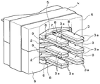
- FIG. 3 is a perspective view showing a transformer according to an embodiment of the present invention.
- FIG. 4 is a perspective view showing a state where the transformer of FIG. 3 is disassembled.
- FIG. 5 is a cross-sectional view in the axial direction of a conventional transformer that is not surrounded by an E-type ferrite core.
- 6 is a perspective view showing a bobbin and a cover member of the high voltage coil of the transformer of FIG.
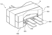
- FIG. 7 is a perspective view of a conventional transformer in which a plurality of high voltage coils and low voltage coils are stacked.
- FIG. 8 is a perspective view showing a state where the transformer of FIG
- This transformer 1 has two high-voltage coils 2 on the primary side and three sets of low-voltage coils on the secondary side. 3, two cover members 5, and the high-voltage coil 2, the low-voltage coil 3, and the E-type ferrite core 6 that surrounds the cover member 5 and forms a closed magnetic circuit.
- the low-voltage coil 3 is a ring-opening ring-shaped flat plate member formed by punching a copper plate, and terminals 3a extending outward are integrally formed at both ends thereof. Further, the low voltage coils 3 are coaxially laminated with an insulating sheet 7 interposed between the two low voltage coils 3.
- the insulating sheet 7 is formed of an annular ring-shaped flat plate member.
- the high-voltage coil 2 has a substantially cylindrical appearance in which a three-layer insulated wire (wire) 9 is wound around a bobbin 4 in which flanges 4b are formed at both ends of a cylindrical winding body 4a having insulation properties. Is formed.
- the high-voltage coil 2 has a wall that is brought into contact with the inner peripheral surface of each of the two low-voltage coils 3 when a pair of low-voltage coils 3 are stacked on both ends in the axial direction. Portions 2a and 2b are formed.
- the wall portions 2a and 2b are formed so as to protrude outward in the axial direction from the bobbin 4 of the high voltage coil 2, and a plurality (6 in the figure) are spaced apart in the circumferential direction of the inner peripheral surface of the low voltage coil 3. One) is formed.
- the wall portion 2a and the wall portion 2b have the same height as the thickness of the pair of low voltage coils 3 and are formed at the same interval. They are arranged alternately with respect to the circumferential direction.
- a rotation stop member 8 protruding outward in the axial direction is formed at the peripheral edge of each flange 4b of the bobbin 4.
- the anti-rotation member 8 is configured such that each anti-rotation member 8 is disposed between the terminals 3a of the two low-voltage coils 3 when a pair of low-voltage coils 3 is disposed between the two high-voltage coils 2.
- the other rotation preventing members 8 are inserted so that one rotation stop member 8 is brought into contact with the inner end of one terminal 3a and the other rotation stop member 8 is brought into contact with the inner end of the other terminal 3a.
- the members 8 are formed alternately.
- cover member 5 is formed in the shape of an annular plate having an insulating property.
- the cover member 5 is a wall that abuts along the inner peripheral surface of each of the two low voltage coils 3 when a pair of the low voltage coils 3 are disposed between the cover member 5 and the high voltage coil 2. Part 5a is formed.
- the wall 5a is formed so as to protrude outward in the axial direction from one end of each cover member 5, and a plurality (6 in the figure) is spaced apart in the circumferential direction of the inner peripheral surface of the low voltage coil 3. One) is formed.
- the wall 5a is formed with the same height and the same interval as the wall 2a and the wall 2b provided at both ends of the bobbin 4 of the high voltage coil 2.
- the wall 5a of one cover member 5 is formed alternately with respect to the circumferential direction of the wall 2a provided at one end of the bobbin 4 of the high voltage coil 2 and the low voltage coil 3.
- the wall portion 5 a of the other cover member 5 is formed alternately with respect to the circumferential direction of the wall portion 2 b provided at the other end portion of the bobbin 4 of the high voltage coil 2 and the low voltage coil 3.
- a rotation stop member 8 protruding outward in the axial direction is formed at the peripheral edge of the cover member 5.
- the anti-rotation member 8 is configured such that when the pair of low-voltage coils 3 is disposed between the high-voltage coil 2 and the cover member 5, the anti-rotation member 8 is connected to the two terminals 3 a of the two low-voltage coils 3. It is formed at a position where it abuts on each outer end.
- the three-layer insulated wire 9 is wound around the winding body 4a of the bobbin 4 of one high-voltage coil 2 and then extended from the one high-voltage coil 2.
- Two high-voltage coils in which one three-layer insulated wire 9 is continuously wound by winding the three-layer insulated wire 9 to be wound around the winding body 4a of the bobbin 4 of the other high-voltage coil 2 Create 2.
- a set of low voltage coils 3 is disposed between two high voltage coils 2.
- the wall portion 2a provided in one high voltage coil 2 and the wall portion 2b provided in the other high voltage coil 2 are fitted, and the two high voltage coils 2 are positioned. Since the wall portions 2a and 2b of the two high voltage coils 2 are in contact with the inner peripheral surfaces of the two low voltage coils 3, the low voltage coils 3 are also positioned at the same time.
- the anti-rotation member 8 provided on the flange 4b of the bobbin 4 of the one high voltage coil 2 is installed.
- the anti-rotation member 8 provided on the flange 4b of the bobbin 4 of the other high-voltage coil 2 is installed.
- Each of the terminals 3a is in contact with the inner end of the terminal 3a on the other side to prevent the pair of low voltage coils 3 from rotating in the circumferential direction.
- a pair of low voltage coils 3 is disposed at both ends in the axial direction of the two stacked high voltage coils 2 so as to be sandwiched between the high voltage coil 2 and the cover member 5.
- the wall 2a provided on one end of the laminated high voltage coil 2 and the wall 5a of one cover member 5 and the wall 2b provided on the other end of the high voltage coil 2 and the other
- the wall portions 5a of the cover members 5 are fitted to each other, and the respective cover members 5 are positioned on the stacked high voltage coils 2.
- the wall portion 2a of the laminated high voltage coil 2 and the wall portion 5a of the cover member 5 and the wall portion 2b of the laminated high voltage coil 2 and the cover are provided on the inner peripheral surface of each of the two sets of low voltage coils. Since the wall 5a of the member 5 is brought into contact, the two sets of the low voltage coils 3 are also positioned at the same time.
- the two high voltage coils 2, the three sets of low voltage coils 3, and the two cover members 5 are surrounded by a pair of E-type ferrite cores 6 and fixed by a binding member k. Assembly is complete.
- three sets of low voltage coils 3 are arranged between the two high voltage coils 2 and between the high voltage coil 2 and the cover member 5, respectively, in the axial direction.
- the wall portions 2a and 2b that are stacked and project from the bobbin 4 of the high-voltage coil 2 in the axial direction and the wall portions 5a that project in the axial direction of the cover member 5 are the low-voltage coils. Since they are alternately arranged along the inner peripheral surface of 3 and positioned in the circumferential direction, the assembly operation can be easily performed and the radial displacement of the set of low voltage coils 3 is prevented. be able to. Thereby, productivity can be improved and it can lead to quality improvement.
- the high-voltage coils 2 can be positioned in the same direction. .
- the low voltage coil 3 is coaxially laminated with the insulating sheet 7 interposed therebetween, the current efficiency can be improved without increasing the thickness and width of the low voltage coil 3. As a result, it is possible to reduce the size of the large current transformer.
- the wall portions 2a and 2b protruding from the bobbin 4 of the high voltage coil 2 and the wall portion 5a protruding from the cover member 5 are brought into contact with the inner peripheral surface of each of the three sets of the low voltage coils 3. Therefore, even if the insulating sheet 7 is interposed between each of the three sets of low voltage coils 3, the radial sheet of the insulating sheet 7 is not displaced in the radial direction, and the low voltage coils 3 are brought into contact with each other. Can be prevented.
- the transformer 1 according to the present invention has been described only in the case where two high-voltage coils 2 and three sets of low-voltage coils 3 are alternately stacked in the axial direction.
- the present invention is not limited to this, and it can be configured by combining more high-voltage coils 2 and low-voltage coils 3.
- the wire for forming the high voltage coil 2 is not limited to the three-layer insulated wire 9 described above, and various wire types can be used based on the specifications of the transformer. Further, for the low voltage coil 3, depending on the magnitude of the flowing current, it is also possible to use a wire having a large wire diameter instead of the above-described ring-opening ring-shaped flat plate member.
- It can be used for power transformers used in electric vehicles and large servers and large current transformers such as DC-DC converters.
Landscapes
- Engineering & Computer Science (AREA)
- Power Engineering (AREA)
- Coils Of Transformers For General Uses (AREA)
- Insulating Of Coils (AREA)
Abstract
高圧用コイルと低圧用コイルを互いの軸線方向に交互に積層する際に、簡便に重ね合わせることができ、かつ電源効率を向上させることが可能なトランスを提供する。本発明は、筒状の巻胴部(4a)の両端に鍔部(4b)が形成されたボビン(4)の当該巻胴部(4a)に線材(9)が巻回された高圧用コイル(2)および開環リング状の平板部材からなる低圧用コイル(3)が互いの軸線方向に交互に積層され、かつ積層された積層体の軸線方向の外側に円環板状のカバー部材(5)が同軸上に各々積層されたトランス(1)において、高圧用コイル(2)とカバー部材(5)との間に低圧用コイル(3)が配設されているとともに、高圧用コイル(2)のボビン(4)から上記軸線方向に各々突出した壁部(2a、2b)と、各々のカバー部材(5)の上記軸線方向に突出した壁部(5a)とが低圧用コイル(3)の内周面に沿って互い違いに配設されて周方向に位置決めされている。
Description
本発明は、低圧用コイルに大電流が流れる電源トランスなどとして用いられるトランスに関するものである。
一般に、電気自動車や大型サーバーなどに使用される電源トランスやDC-DCコンバーターとして、2次側の低圧用コイルに100A以上の大電流が流れるトランスが用いられている。このようなトランスにおいては、通常、低圧用コイルとして、抵抗値が小さい金属製の平板を用いることにより、上記大電流化の対応を行っている。
ところで、上記低圧用コイルを金属製の平板で構成した場合には、2次側の低圧用コイルと1次側の高圧用コイルとを層巻き構造にすることができないため、低圧用コイルと高圧用コイルとを分割して配置させる構造を採っていたが、当該構造によっては結合が悪く、所望の特性を得ることが難しいという問題点があった。
そこで、従来、図5~図8に示すように、ボビン40の巻胴部40aに線材tが巻回された高圧用コイル20、および開環リング状の平板部材からなる低圧用コイル30が互いの軸線方向に交互に積層され、かつ積層された積層体の軸線方向の外側に、円環板状のカバー部材50が同軸上に各々積層されたトランス10が用いられていた。なお、図中符号40bは、ボビン40の鍔部である。また図中符号60は、低圧用コイル30および高圧用コイル20を囲繞して、日字状の閉磁路を形成する一対のE型フェライトコアであり、カバー部材50が、当該E型フェライトコア60と低圧用コイル30との間に介装された絶縁部材である。
上記構成からなる従来のトランス10によれば、高圧用コイル20を2枚の低圧用コイル30で挟むことにより結合を高めることができ、優れた特性を得ることが可能になる。
なお、上記構成を備えた電源トランス10は、例えば、下記特許文献1にも開示されている。
なお、上記構成を備えた電源トランス10は、例えば、下記特許文献1にも開示されている。
上記従来の構成のトランス10において、さらに結合を良くして特性を向上させようとする場合には、高圧用コイル20も分割構造にして、これら高圧用コイル20により低圧用コイル30を挟み込み、複数の低圧用コイル30と高圧用コイル20とを軸線方向に、交互に積層した構成を採用することが考えられる。
しかしながら、複数の低圧用コイル30と高圧用コイル20とを軸線方向に交互に積層したトランス10では、各々を組み付ける際に位置を合わせるのに手間が掛かり、作業効率が悪いという問題がある。また、上手く位置合わせをして組み付けた場合でも、軸線方向のガタにより、各々のコイルの間に隙間が生じてしまい、径方向へのズレの要因となり、所望の特性を得ることが難しいく、品質の低下に繋がってしまうという問題点もある。
さらに、大きな電流容量に対応するために、平板状部材からなる低圧用コイル30の板厚や幅を増やし、断面積を大きくすることで対応しているが、その場合には、トランス10自体の形状が大きくなってしまうという問題点もある。
本発明は、かかる事情に鑑みてなされたもので、高圧用コイルと低圧用コイルを互いの軸線方向に交互に積層する際に、簡便に重ね合わせることができ、かつ電源効率を向上させることが可能なトランスを提供することを課題とするものである。
上記課題を解決するために、請求項1に記載の発明は、筒状の巻胴部の両端に鍔部が形成されたボビンの当該巻胴部に線材が巻回された高圧用コイルおよび開環リング状の平板部材からなる低圧用コイルが互いの軸線方向に交互に積層され、かつ積層された積層体の軸線方向の外側に円環板状のカバー部材が同軸上に各々積層されたトランスにおいて、上記高圧用コイルと上記カバー部材との間に上記低圧用コイルが配設されているとともに、上記高圧用コイルの上記ボビンから上記軸線方向に各々突出した壁部と、各々の上記カバー部材の上記軸線方向に突出した壁部とが上記低圧用コイルの内周面に沿って互い違いに配設されて周方向に位置決めされていることを特徴とするものである。
また、請求項2に記載の発明は、請求項1に記載の発明において、上記高圧用コイルは、上記軸線方向に二つ以上配設されているとともに、当該高圧用コイルの各々の間に上記低圧用コイルが配置され、かつ当該低圧用コイルの内周面に沿って上記高圧用コイルの各々の上記壁部が互い違いに配設されて周方向に位置決めされていることを特徴とするものである。
さらに、請求項3に記載の発明は、請求項1または2に記載の発明において、上記低圧用コイルは、絶縁シートを間に介して二枚以上が同軸上に積層されていることを特徴とするものである。
請求項1~3に記載の本発明によれば、高圧用コイルとカバー部材との間に、低圧用コイルが配設されて軸線方向に積層されているとともに、当該高圧用コイルのボビンから上記軸線方向に各々突出した壁部と、当該カバー部材の上記軸線方向に各々突出した壁部とが、当該低圧用コイルの内周面に沿って互い違いに配設されて、周方向に位置決めされているため、組み付け作業を容易に行うことができるとともに、上記低圧用コイルの径方向のズレを防止することができる。これにより、生産性を向上されることができ、品質向上に繋げることができる。
請求項2に記載の発明によれば、上記高圧用コイルが、上記軸線方向に二つ以上配設されているとともに、当該高圧用コイルの各々の間に上記低圧用コイルが配置され、かつ当該低圧用コイルの内周面に沿って上、記高圧用コイルの各々の上記壁部が互い違いに配設されて周方向に位置決めされているため、複数の上記高圧用コイルおよび低圧用コイルを積層して配置する場合でも、容易に組み立てることができる。この結果、生産性を向上されることができるとともに、歩留まり歩留まりを向上させることができる。
請求項3に記載の発明によれば、上記低圧用コイルは、絶縁シートを間に介して二枚以上が同軸上に積層されているため、上記低圧用コイルの厚さや幅寸法を増やすことなく、電流効率を向上させることができる。これにより、大電流トランスの小型化を図ることができる。
また、上記高圧用コイルの上記ボビンから突出した壁部、および上記カバー部材から突出した壁部が、上記低圧用コイルの内周面に当接されているため、積層された上記低圧用コイルの間に絶縁シートが介在させていても、当該絶縁シートの径方向へのズレの発生をなくして、上記低圧用コイル同士の接触を防止することができる。
図1~図4は、本発明に係るトランスの一実施形態を示すもので、このトランス1は、1次側となる二つの高圧用コイル2と、2次側となる三組の低圧用コイル3と、二つのカバー部材5と、これら高圧用コイル2および低圧用コイル3ならびにカバー部材5を囲繞して閉磁路を形成するE型フェライトコア6とから概略構成されたものである。
ここで、低圧用コイル3は、銅板を打ち抜き加工することによって形成された開環リング状の平板部材であり、その両端部には外方に延出する端子3aが一体に形成されている。さらに、二枚の低圧用コイル3の間に絶縁シート7を介装して、各々の低圧用コイル3が同軸上に積層されている。また、絶縁シート7は、円環リング状の平板部材により形成されている。
そして、高圧用コイル2は、絶縁性を有する筒状の巻胴部4aの両端に鍔部4bが形成されたボビン4に、三層絶縁電線(線材)9が巻回された外観略円筒状に形成されている。また、高圧用コイル2には、一組の低圧用コイル3を軸線方向の両端部に積層した際に、二枚の当該低圧用コイル3の各々の内周面に沿って当接される壁部2a、2bが形成されている。
この壁部2a、2bは、高圧用コイル2のボビン4から軸線方向外方に突出して形成されているとともに、低圧用コイル3の内周面の周方向に間隔を置いて複数(図では6つ)形成されている。また、壁部2aおよび壁部2bは、一組の低圧用コイル3の厚さ寸法と同一の寸法の高さを有し、また同一の間隔により形成されているとともに、低圧用コイル3の円周方向に対して互い違いに配置されて形成されている。
また、ボビン4の各々の鍔部4bの周縁部には、上記軸線方向外方に突出した回転止め部材8が形成されている。この回転止め部材8は、二つの当該高圧用コイル2の間に一組の低圧用コイル3を配設した際に、各々の回転止め部材8が二枚の低圧用コイル3の端子3a間に挿入されるとともに、一方の端子3aの内側の端部に一方の回転止め部材8が、他方の端子3aの内側の端部に他方の回転止め部材8当接されるように、互いの回転止め部材8が互い違いに配置されて形成されている。
そして、カバー部材5は、絶縁性を有する円環板状に形成されている。このカバー部材5は、高圧用コイル2との間に、一組の低圧用コイル3を配設した際に、二枚の低圧用コイル3の各々の内周面に沿って当接される壁部5aが形成されている。
この壁部5aは、各々のカバー部材5の一端部から上記軸線方向外方に突出して形成されているとともに、低圧用コイル3の内周面の周方向に間隔を置いて複数(図では6つ)形成されている。この壁部5aは、高圧用コイル2のボビン4の両端部に設けられた壁部2aおよび壁部2bと同一の高さ寸法、および同一の間隔により形成されている。
また、一方のカバー部材5の壁部5aは、高圧用コイル2のボビン4の一端部に設けられた壁部2aと、低圧用コイル3の円周方向に対して互い違いに形成されているとともに、他方のカバー部材5の壁部5aは、高圧用コイル2のボビン4の他端部に設けられた壁部2bと、低圧用コイル3の円周方向に対して互い違いに形成されている。
さらに、カバー部材5の周縁部には、上記軸線方向外方に突出した回転止め部材8が形成されている。この回転止め部材8は、高圧用コイル2とカバー部材5の間に一組の低圧用コイル3を配設した際に、回転止め部材8が二枚の低圧用コイル3の二つの端子3aの外側の各々の端部に当接される位置に形成されている。
上記構成からなるトランス1を組み立てる際には、まず、一方の高圧用コイル2のボビン4の巻胴部4aに、三層絶縁電線9をα巻きし、次いで当該一方の高圧用コイル2から延出する三層絶縁電線9を他方の高圧用コイル2のボビン4の巻胴部4aにα巻きすることにより、1本の三層絶縁電線9が連続して巻回された二つの高圧用コイル2を作成する。
次いで、図4に示すように、一組の低圧用コイル3を二つの高圧用コイル2の間に挟むようにして配設する。その際に、一方の高圧用コイル2に設けられた壁部2aと、他方の高圧用コイル2に設けられた壁部2bとが嵌合されて、二つの高圧用コイル2が位置決めされるとともに、二枚の低圧用コイル3の各々の内周面に二つの高圧用コイル2の壁部2a、2bが当接されるため、当該低圧用コイル3も同時に位置決めされる。
また、二つの高圧用コイル2の間に、一組の低圧用コイル3を配設して組み付けた際に、一方の高圧用コイル2のボビン4の鍔部4bに設けられた回転止め部材8が、二枚の低圧用コイル3の一方側の端子3aの内側の端部に各々当接され、また他方の高圧用コイル2のボビン4の鍔部4bに設けられた回転止め部材8が、他方側の端子3aの内側の端部に各々当接され、一組の低圧用コイル3の周方向の回転が防止される。
そして、積層された二つの高圧用コイル2の軸線方向の両端部に、当該高圧用コイル2とカバー部材5との間に挟むようにして、一組の低圧用コイル3を配設する。その際に、積層された高圧用コイル2の一端側に設けられた壁部2aと一方のカバー部材5の壁部5a、および高圧用コイル2の他端側に設けられた壁部2bと他方のカバー部材5の壁部5aが各々嵌合されて、積層された高圧用コイル2に各々のカバー部材5が位置決めされる。また、二組の低圧用コイルの各々の内周面に、積層された高圧用コイル2の壁部2aとカバー部材5の壁部5a、および積層された高圧用コイル2の壁部2bとカバー部材5の壁部5aが当接されるため、二組の当該低圧用コイル3も各々同時に位置決めされる。
また、高圧用コイル2とカバー部材5の間に、一組の低圧用コイル3を配設して組み付けた際に、高圧用コイル2のボビン4の鍔部4bに設けられた回転止め部材8が、二枚の低圧用コイル3の一方側の端子3aの内側に各々当接され、またカバー部材5の円端部に設けられた二つの回転止め部材8の間に、一方の低圧用コイル3の端子3aの外側に当接され、一組の当該低圧用コイル3の周方向の回転が防止される。
そして、一対のE型フェライトコア6によって、これら二つの高圧用コイル2および三組の低圧用コイル3、ならびに二つのカバー部材5を囲繞して、結束部材kにより固定することにより、トランス1の組み立てが完了する。
以上の構成からなるトランス1によれば、二つの高圧用コイル2の間、および高圧用コイル2とカバー部材5との間に、三組の低圧用コイル3が各々配設されて軸線方向に積層されているとともに、高圧用コイル2のボビン4から上記軸線方向に各々突出した壁部2a、2bと、当該カバー部材5の上記軸線方向に突出した各々の壁部5aとが、低圧用コイル3の内周面に沿って互い違いに配設されて、周方向に位置決めされているため、組み付け作業を容易に行うことができるとともに、一組の低圧用コイル3の径方向のズレを防止することができる。これにより、生産性を向上されることができ、品質向上に繋げることができる。また、例えば、二つの高圧用コイル2のボビン4が楕円型であっても、これらを互いの軸線方向に積層した際に、当該高圧用コイル2同士を同一方向に位置決めする
ことが可能となる。
ことが可能となる。
また、低圧用コイル3は、絶縁シート7を間に介して同軸上に積層されているため、低圧用コイル3の厚さや幅寸法を増やすことなく、電流効率を向上させることができる。この結果、大電流トランスの小型化を図ることができる。
さらに、高圧用コイル2のボビン4から突出した壁部2a、2b、およびカバー部材5から突出した壁部5aが、三組の低圧用コイル3の各々の内周面に沿って当接されている
ため、三組の低圧用コイル3の各々の間に、絶縁シート7が介在させていても、当該絶縁シート7の径方向へのズレの発生をなくして、低圧用コイル3同士の接触を防止することができる。
ため、三組の低圧用コイル3の各々の間に、絶縁シート7が介在させていても、当該絶縁シート7の径方向へのズレの発生をなくして、低圧用コイル3同士の接触を防止することができる。
なお、上記実施形態においては、本発明に係るトランス1を、二つの高圧用コイル2と三組の低圧用コイル3を軸線方向に交互に積層配置した場合についてのみ説明したが、本発明はこれに限定されるものではなく、より多くの高圧用コイル2と低圧用コイル3とを組み合わせることによって構成することもできる。
また、高圧用コイル2を形成するための線材としても、上述した三層絶縁電線9に限らず、トランスの仕様に基づいて、様々な線種の線材を用いることができる。
さらに、低圧用コイル3についても、流れる電流の大きさによっては、上述した開環リング状の平板部材に代えて、線径の大きな線材を用いることも可能である。
さらに、低圧用コイル3についても、流れる電流の大きさによっては、上述した開環リング状の平板部材に代えて、線径の大きな線材を用いることも可能である。
電気自動車や大型サーバーなどに使用される電源トランスやDC-DCコンバーターなどの大電流トランスに利用することができる。
1 トランス
2 高圧用コイル
2a、2b 壁部
3 低圧用コイル
4 ボビン
4a 巻胴部
4b 鍔部
5 カバー部材
5a 壁部
6 E型フェライトコア
7 絶縁シート
8 低圧用コイル回転止め部材
9 線材
10 トランス
20 高圧用コイル
30 低圧用コイル
40 ボビン
40a 巻胴部
40b 鍔部
50 カバー部材
60 E型フェライトコア
t 線材
2 高圧用コイル
2a、2b 壁部
3 低圧用コイル
4 ボビン
4a 巻胴部
4b 鍔部
5 カバー部材
5a 壁部
6 E型フェライトコア
7 絶縁シート
8 低圧用コイル回転止め部材
9 線材
10 トランス
20 高圧用コイル
30 低圧用コイル
40 ボビン
40a 巻胴部
40b 鍔部
50 カバー部材
60 E型フェライトコア
t 線材
Claims (3)
- 筒状の巻胴部の両端に鍔部が形成されたボビンの当該巻胴部に線材が巻回された高圧用コイルおよび開環リング状の平板部材からなる低圧用コイルが互いの軸線方向に交互に積層され、かつ積層された積層体の軸線方向の外側に円環板状のカバー部材が同軸上に各々積層されたトランスにおいて、
上記高圧用コイルと上記カバー部材との間に上記低圧用コイルが配設されているとともに、上記高圧用コイルの上記ボビンから上記軸線方向に各々突出した壁部と、各々の上記カバー部材の上記軸線方向に突出した壁部とが上記低圧用コイルの内周面に沿って互い違いに配設されて周方向に位置決めされていることを特徴とするトランス。 - 上記高圧用コイルは、上記軸線方向に二つ以上配設されているとともに、当該高圧用コイルの各々の間に上記低圧用コイルが配置され、かつ当該低圧用コイルの内周面に沿って上記高圧用コイルの各々の上記壁部が互い違いに配設されて周方向に位置決めされていることを特徴とする請求項1に記載のトランス。
- 上記低圧用コイルは、絶縁シートを間に介して上記開環リング状の平板部材が二枚以上同軸上に積層されていることを特徴とする請求項1または2に記載のトランス。
Priority Applications (1)
| Application Number | Priority Date | Filing Date | Title |
|---|---|---|---|
| US14/648,831 US9640307B2 (en) | 2012-12-27 | 2013-10-29 | Transformer |
Applications Claiming Priority (2)
| Application Number | Priority Date | Filing Date | Title |
|---|---|---|---|
| JP2012-285024 | 2012-12-27 | ||
| JP2012285024A JP6079225B2 (ja) | 2012-12-27 | 2012-12-27 | トランス |
Publications (1)
| Publication Number | Publication Date |
|---|---|
| WO2014103121A1 true WO2014103121A1 (ja) | 2014-07-03 |
Family
ID=51020259
Family Applications (1)
| Application Number | Title | Priority Date | Filing Date |
|---|---|---|---|
| PCT/JP2013/006385 Ceased WO2014103121A1 (ja) | 2012-12-27 | 2013-10-29 | トランス |
Country Status (3)
| Country | Link |
|---|---|
| US (1) | US9640307B2 (ja) |
| JP (1) | JP6079225B2 (ja) |
| WO (1) | WO2014103121A1 (ja) |
Cited By (2)
| Publication number | Priority date | Publication date | Assignee | Title |
|---|---|---|---|---|
| CN104835635A (zh) * | 2015-05-07 | 2015-08-12 | 江苏扬动电气有限公司 | 变压器高压线圈分级式端绝缘强化结构 |
| JP2016032069A (ja) * | 2014-07-30 | 2016-03-07 | Fdk株式会社 | トランス |
Families Citing this family (20)
| Publication number | Priority date | Publication date | Assignee | Title |
|---|---|---|---|---|
| JP6239478B2 (ja) * | 2014-09-29 | 2017-11-29 | 日立オートモティブシステムズ株式会社 | トランス構造 |
| CN205542333U (zh) * | 2016-03-16 | 2016-08-31 | 光宝电子(广州)有限公司 | 变压器结构 |
| JP6874284B2 (ja) * | 2016-06-16 | 2021-05-19 | 富士電機株式会社 | 高周波トランス |
| JP6893396B2 (ja) * | 2016-06-16 | 2021-06-23 | 富士電機株式会社 | 高電圧高周波絶縁トランス |
| CN110419085B (zh) * | 2017-03-17 | 2021-11-12 | 三菱电机株式会社 | 变压器 |
| US20180358162A1 (en) * | 2017-06-08 | 2018-12-13 | Delta Electronics (Shanghai) Co.,Ltd. | Magnetic component |
| US11581118B2 (en) * | 2017-06-08 | 2023-02-14 | Delta Electronics (Shanghai) Co., Ltd. | Transformer and power supply module with high thermal efficiency |
| JP7269699B2 (ja) * | 2017-07-27 | 2023-05-09 | 富士電機株式会社 | コア、トランス |
| JP7004142B2 (ja) * | 2017-09-15 | 2022-01-21 | Tdk株式会社 | コイル装置 |
| JP6939410B2 (ja) * | 2017-10-26 | 2021-09-22 | 富士電機株式会社 | トランス |
| CN107610913B (zh) * | 2017-11-09 | 2020-01-31 | 台达电子企业管理(上海)有限公司 | 磁性元件、金属环状绕组及其制备方法 |
| CN108364762A (zh) * | 2018-01-12 | 2018-08-03 | 苏州汇川技术有限公司 | 移相整流变压器 |
| KR102007750B1 (ko) * | 2018-04-25 | 2019-08-06 | 씨케이티주식회사 | 평판형 트랜스포머의 코일부품 및 그 제조방법 |
| US10971298B2 (en) | 2018-06-25 | 2021-04-06 | Pin Shine Industrial Co., Ltd. | Passive component structure |
| DE102018116258A1 (de) * | 2018-07-05 | 2020-01-09 | Pin Shine Industrial Co., Ltd. | Aufbau für passive Bauelemente |
| JP2020202219A (ja) * | 2019-06-06 | 2020-12-17 | 株式会社デンソー | トランス |
| JP7251377B2 (ja) * | 2019-07-19 | 2023-04-04 | スミダコーポレーション株式会社 | 磁気結合型リアクトル装置 |
| CN110660563A (zh) * | 2019-10-12 | 2020-01-07 | 台达电子企业管理(上海)有限公司 | 磁性组件及电源模块 |
| CN114823083B (zh) * | 2019-10-16 | 2025-09-02 | 台达电子企业管理(上海)有限公司 | 整合式磁性元件 |
| JP7659387B2 (ja) * | 2020-12-03 | 2025-04-09 | 新電元工業株式会社 | コイル装置 |
Citations (3)
| Publication number | Priority date | Publication date | Assignee | Title |
|---|---|---|---|---|
| JPS5466118U (ja) * | 1977-10-19 | 1979-05-10 | ||
| JP2001284142A (ja) * | 2000-03-31 | 2001-10-12 | Densei Lambda Kk | トランス及びトランスを備えた電源装置 |
| JP2002359110A (ja) * | 2001-05-31 | 2002-12-13 | Totoku Electric Co Ltd | 巻線ボビンの結合方法 |
Family Cites Families (5)
| Publication number | Priority date | Publication date | Assignee | Title |
|---|---|---|---|---|
| JPS5466118A (en) | 1977-11-04 | 1979-05-28 | Onkyo Kk | Method of fabricating speaker vibrating plate |
| JP3755729B2 (ja) | 2000-03-21 | 2006-03-15 | Tdk株式会社 | 電源トランス |
| US6522233B1 (en) * | 2001-10-09 | 2003-02-18 | Tdk Corporation | Coil apparatus |
| TWI379326B (en) * | 2009-11-19 | 2012-12-11 | Delta Electronics Inc | Transformer with modular winding bobbin devices |
| CN102568782B (zh) * | 2010-12-20 | 2015-05-13 | 三星电机株式会社 | 变压器和包括该变压器的平板显示装置 |
-
2012
- 2012-12-27 JP JP2012285024A patent/JP6079225B2/ja active Active
-
2013
- 2013-10-29 US US14/648,831 patent/US9640307B2/en not_active Expired - Fee Related
- 2013-10-29 WO PCT/JP2013/006385 patent/WO2014103121A1/ja not_active Ceased
Patent Citations (3)
| Publication number | Priority date | Publication date | Assignee | Title |
|---|---|---|---|---|
| JPS5466118U (ja) * | 1977-10-19 | 1979-05-10 | ||
| JP2001284142A (ja) * | 2000-03-31 | 2001-10-12 | Densei Lambda Kk | トランス及びトランスを備えた電源装置 |
| JP2002359110A (ja) * | 2001-05-31 | 2002-12-13 | Totoku Electric Co Ltd | 巻線ボビンの結合方法 |
Cited By (2)
| Publication number | Priority date | Publication date | Assignee | Title |
|---|---|---|---|---|
| JP2016032069A (ja) * | 2014-07-30 | 2016-03-07 | Fdk株式会社 | トランス |
| CN104835635A (zh) * | 2015-05-07 | 2015-08-12 | 江苏扬动电气有限公司 | 变压器高压线圈分级式端绝缘强化结构 |
Also Published As
| Publication number | Publication date |
|---|---|
| JP6079225B2 (ja) | 2017-02-15 |
| US9640307B2 (en) | 2017-05-02 |
| US20150318098A1 (en) | 2015-11-05 |
| JP2014127650A (ja) | 2014-07-07 |
Similar Documents
| Publication | Publication Date | Title |
|---|---|---|
| JP6079225B2 (ja) | トランス | |
| JP2013062399A (ja) | トランス | |
| JP6523626B2 (ja) | トランス | |
| JP2015185725A (ja) | トランス | |
| GB2535822B (en) | Planar transformer with conductor plates forming windings | |
| JP7063579B2 (ja) | 変圧器、およびコイルボビン | |
| JP6471489B2 (ja) | コイル部品用ボビンおよびコイル部品の製造方法 | |
| JP2010232390A (ja) | トランス | |
| JP6561460B2 (ja) | コイル部品 | |
| JP6171384B2 (ja) | トランス | |
| JP2018060886A (ja) | 外鉄形変圧器 | |
| JP2014075535A (ja) | 誘導機器 | |
| JP2008177453A (ja) | 巻線構造 | |
| US8508323B2 (en) | Transformer | |
| US20160268037A1 (en) | Stationary Induction Electric Apparatus and Method for Making the Same | |
| US8547193B2 (en) | Stationary induction apparatus | |
| JP2012164914A (ja) | トランス | |
| WO2014162684A1 (ja) | 電源トランス | |
| US20160111206A1 (en) | Transformer | |
| JP5177231B2 (ja) | アーク溶接機に用いる変圧器およびアーク溶接機に用いる変圧器の組み立て方法 | |
| JP2008270347A (ja) | トランス | |
| JP2014049681A (ja) | トランス | |
| JP2011204990A (ja) | ユニット構成のコイル変圧器 | |
| JP2016100465A (ja) | チョークコイル | |
| JP2015207577A (ja) | コイル |
Legal Events
| Date | Code | Title | Description |
|---|---|---|---|
| 121 | Ep: the epo has been informed by wipo that ep was designated in this application |
Ref document number: 13867268 Country of ref document: EP Kind code of ref document: A1 |
|
| WWE | Wipo information: entry into national phase |
Ref document number: 14648831 Country of ref document: US |
|
| NENP | Non-entry into the national phase |
Ref country code: DE |
|
| 122 | Ep: pct application non-entry in european phase |
Ref document number: 13867268 Country of ref document: EP Kind code of ref document: A1 |