WO2014102953A1 - 充電装置、および、充電装置の正常性確認方法 - Google Patents
充電装置、および、充電装置の正常性確認方法 Download PDFInfo
- Publication number
- WO2014102953A1 WO2014102953A1 PCT/JP2012/083821 JP2012083821W WO2014102953A1 WO 2014102953 A1 WO2014102953 A1 WO 2014102953A1 JP 2012083821 W JP2012083821 W JP 2012083821W WO 2014102953 A1 WO2014102953 A1 WO 2014102953A1
- Authority
- WO
- WIPO (PCT)
- Prior art keywords
- leakage
- charging
- controller
- charge controller
- breaker
- Prior art date
- Legal status (The legal status is an assumption and is not a legal conclusion. Google has not performed a legal analysis and makes no representation as to the accuracy of the status listed.)
- Ceased
Links
Images

Classifications
-
- H—ELECTRICITY
- H02—GENERATION; CONVERSION OR DISTRIBUTION OF ELECTRIC POWER
- H02H—EMERGENCY PROTECTIVE CIRCUIT ARRANGEMENTS
- H02H3/00—Emergency protective circuit arrangements for automatic disconnection directly responsive to an undesired change from normal electric working condition with or without subsequent reconnection ; integrated protection
- H02H3/02—Details
- H02H3/05—Details with means for increasing reliability, e.g. redundancy arrangements
-
- B—PERFORMING OPERATIONS; TRANSPORTING
- B60—VEHICLES IN GENERAL
- B60L—PROPULSION OF ELECTRICALLY-PROPELLED VEHICLES; SUPPLYING ELECTRIC POWER FOR AUXILIARY EQUIPMENT OF ELECTRICALLY-PROPELLED VEHICLES; ELECTRODYNAMIC BRAKE SYSTEMS FOR VEHICLES IN GENERAL; MAGNETIC SUSPENSION OR LEVITATION FOR VEHICLES; MONITORING OPERATING VARIABLES OF ELECTRICALLY-PROPELLED VEHICLES; ELECTRIC SAFETY DEVICES FOR ELECTRICALLY-PROPELLED VEHICLES
- B60L3/00—Electric devices on electrically-propelled vehicles for safety purposes; Monitoring operating variables, e.g. speed, deceleration or energy consumption
-
- B—PERFORMING OPERATIONS; TRANSPORTING
- B60—VEHICLES IN GENERAL
- B60L—PROPULSION OF ELECTRICALLY-PROPELLED VEHICLES; SUPPLYING ELECTRIC POWER FOR AUXILIARY EQUIPMENT OF ELECTRICALLY-PROPELLED VEHICLES; ELECTRODYNAMIC BRAKE SYSTEMS FOR VEHICLES IN GENERAL; MAGNETIC SUSPENSION OR LEVITATION FOR VEHICLES; MONITORING OPERATING VARIABLES OF ELECTRICALLY-PROPELLED VEHICLES; ELECTRIC SAFETY DEVICES FOR ELECTRICALLY-PROPELLED VEHICLES
- B60L3/00—Electric devices on electrically-propelled vehicles for safety purposes; Monitoring operating variables, e.g. speed, deceleration or energy consumption
- B60L3/04—Cutting off the power supply under fault conditions
-
- B—PERFORMING OPERATIONS; TRANSPORTING
- B60—VEHICLES IN GENERAL
- B60L—PROPULSION OF ELECTRICALLY-PROPELLED VEHICLES; SUPPLYING ELECTRIC POWER FOR AUXILIARY EQUIPMENT OF ELECTRICALLY-PROPELLED VEHICLES; ELECTRODYNAMIC BRAKE SYSTEMS FOR VEHICLES IN GENERAL; MAGNETIC SUSPENSION OR LEVITATION FOR VEHICLES; MONITORING OPERATING VARIABLES OF ELECTRICALLY-PROPELLED VEHICLES; ELECTRIC SAFETY DEVICES FOR ELECTRICALLY-PROPELLED VEHICLES
- B60L53/00—Methods of charging batteries, specially adapted for electric vehicles; Charging stations or on-board charging equipment therefor; Exchange of energy storage elements in electric vehicles
- B60L53/10—Methods of charging batteries, specially adapted for electric vehicles; Charging stations or on-board charging equipment therefor; Exchange of energy storage elements in electric vehicles characterised by the energy transfer between the charging station and the vehicle
- B60L53/14—Conductive energy transfer
-
- B—PERFORMING OPERATIONS; TRANSPORTING
- B60—VEHICLES IN GENERAL
- B60L—PROPULSION OF ELECTRICALLY-PROPELLED VEHICLES; SUPPLYING ELECTRIC POWER FOR AUXILIARY EQUIPMENT OF ELECTRICALLY-PROPELLED VEHICLES; ELECTRODYNAMIC BRAKE SYSTEMS FOR VEHICLES IN GENERAL; MAGNETIC SUSPENSION OR LEVITATION FOR VEHICLES; MONITORING OPERATING VARIABLES OF ELECTRICALLY-PROPELLED VEHICLES; ELECTRIC SAFETY DEVICES FOR ELECTRICALLY-PROPELLED VEHICLES
- B60L53/00—Methods of charging batteries, specially adapted for electric vehicles; Charging stations or on-board charging equipment therefor; Exchange of energy storage elements in electric vehicles
- B60L53/10—Methods of charging batteries, specially adapted for electric vehicles; Charging stations or on-board charging equipment therefor; Exchange of energy storage elements in electric vehicles characterised by the energy transfer between the charging station and the vehicle
- B60L53/14—Conductive energy transfer
- B60L53/16—Connectors, e.g. plugs or sockets, specially adapted for charging electric vehicles
-
- B—PERFORMING OPERATIONS; TRANSPORTING
- B60—VEHICLES IN GENERAL
- B60L—PROPULSION OF ELECTRICALLY-PROPELLED VEHICLES; SUPPLYING ELECTRIC POWER FOR AUXILIARY EQUIPMENT OF ELECTRICALLY-PROPELLED VEHICLES; ELECTRODYNAMIC BRAKE SYSTEMS FOR VEHICLES IN GENERAL; MAGNETIC SUSPENSION OR LEVITATION FOR VEHICLES; MONITORING OPERATING VARIABLES OF ELECTRICALLY-PROPELLED VEHICLES; ELECTRIC SAFETY DEVICES FOR ELECTRICALLY-PROPELLED VEHICLES
- B60L53/00—Methods of charging batteries, specially adapted for electric vehicles; Charging stations or on-board charging equipment therefor; Exchange of energy storage elements in electric vehicles
- B60L53/60—Monitoring or controlling charging stations
- B60L53/65—Monitoring or controlling charging stations involving identification of vehicles or their battery types
-
- B—PERFORMING OPERATIONS; TRANSPORTING
- B60—VEHICLES IN GENERAL
- B60L—PROPULSION OF ELECTRICALLY-PROPELLED VEHICLES; SUPPLYING ELECTRIC POWER FOR AUXILIARY EQUIPMENT OF ELECTRICALLY-PROPELLED VEHICLES; ELECTRODYNAMIC BRAKE SYSTEMS FOR VEHICLES IN GENERAL; MAGNETIC SUSPENSION OR LEVITATION FOR VEHICLES; MONITORING OPERATING VARIABLES OF ELECTRICALLY-PROPELLED VEHICLES; ELECTRIC SAFETY DEVICES FOR ELECTRICALLY-PROPELLED VEHICLES
- B60L58/00—Methods or circuit arrangements for monitoring or controlling batteries or fuel cells, specially adapted for electric vehicles
- B60L58/10—Methods or circuit arrangements for monitoring or controlling batteries or fuel cells, specially adapted for electric vehicles for monitoring or controlling batteries
- B60L58/12—Methods or circuit arrangements for monitoring or controlling batteries or fuel cells, specially adapted for electric vehicles for monitoring or controlling batteries responding to state of charge [SoC]
-
- H—ELECTRICITY
- H02—GENERATION; CONVERSION OR DISTRIBUTION OF ELECTRIC POWER
- H02J—ELECTRIC POWER NETWORKS; CIRCUIT ARRANGEMENTS OR SYSTEMS FOR SUPPLYING OR DISTRIBUTING ELECTRIC POWER; SYSTEMS FOR STORING ELECTRIC ENERGY
- H02J7/00—Circuit arrangements for charging or discharging batteries or for supplying loads from batteries
- H02J7/60—Circuit arrangements for charging or discharging batteries or for supplying loads from batteries including safety or protection arrangements
- H02J7/64—Circuit arrangements for charging or discharging batteries or for supplying loads from batteries including safety or protection arrangements against overvoltage
-
- B—PERFORMING OPERATIONS; TRANSPORTING
- B60—VEHICLES IN GENERAL
- B60L—PROPULSION OF ELECTRICALLY-PROPELLED VEHICLES; SUPPLYING ELECTRIC POWER FOR AUXILIARY EQUIPMENT OF ELECTRICALLY-PROPELLED VEHICLES; ELECTRODYNAMIC BRAKE SYSTEMS FOR VEHICLES IN GENERAL; MAGNETIC SUSPENSION OR LEVITATION FOR VEHICLES; MONITORING OPERATING VARIABLES OF ELECTRICALLY-PROPELLED VEHICLES; ELECTRIC SAFETY DEVICES FOR ELECTRICALLY-PROPELLED VEHICLES
- B60L2250/00—Driver interactions
- B60L2250/20—Driver interactions by driver identification
-
- H—ELECTRICITY
- H02—GENERATION; CONVERSION OR DISTRIBUTION OF ELECTRIC POWER
- H02H—EMERGENCY PROTECTIVE CIRCUIT ARRANGEMENTS
- H02H7/00—Emergency protective circuit arrangements specially adapted for specific types of electric machines or apparatus or for sectionalised protection of cable or line systems, and effecting automatic switching in the event of an undesired change from normal working conditions
- H02H7/18—Emergency protective circuit arrangements specially adapted for specific types of electric machines or apparatus or for sectionalised protection of cable or line systems, and effecting automatic switching in the event of an undesired change from normal working conditions for batteries; for accumulators
-
- H—ELECTRICITY
- H02—GENERATION; CONVERSION OR DISTRIBUTION OF ELECTRIC POWER
- H02J—ELECTRIC POWER NETWORKS; CIRCUIT ARRANGEMENTS OR SYSTEMS FOR SUPPLYING OR DISTRIBUTING ELECTRIC POWER; SYSTEMS FOR STORING ELECTRIC ENERGY
- H02J7/00—Circuit arrangements for charging or discharging batteries or for supplying loads from batteries
- H02J7/40—Circuit arrangements for charging or discharging batteries or for supplying loads from batteries characterised by the exchange of charge or discharge related data
- H02J7/47—Arrangements for checking compatibility or authentication between one component, e.g. a battery or a battery charger, and another component, e.g. a power source
-
- Y—GENERAL TAGGING OF NEW TECHNOLOGICAL DEVELOPMENTS; GENERAL TAGGING OF CROSS-SECTIONAL TECHNOLOGIES SPANNING OVER SEVERAL SECTIONS OF THE IPC; TECHNICAL SUBJECTS COVERED BY FORMER USPC CROSS-REFERENCE ART COLLECTIONS [XRACs] AND DIGESTS
- Y02—TECHNOLOGIES OR APPLICATIONS FOR MITIGATION OR ADAPTATION AGAINST CLIMATE CHANGE
- Y02T—CLIMATE CHANGE MITIGATION TECHNOLOGIES RELATED TO TRANSPORTATION
- Y02T10/00—Road transport of goods or passengers
- Y02T10/60—Other road transportation technologies with climate change mitigation effect
- Y02T10/70—Energy storage systems for electromobility, e.g. batteries
-
- Y—GENERAL TAGGING OF NEW TECHNOLOGICAL DEVELOPMENTS; GENERAL TAGGING OF CROSS-SECTIONAL TECHNOLOGIES SPANNING OVER SEVERAL SECTIONS OF THE IPC; TECHNICAL SUBJECTS COVERED BY FORMER USPC CROSS-REFERENCE ART COLLECTIONS [XRACs] AND DIGESTS
- Y02—TECHNOLOGIES OR APPLICATIONS FOR MITIGATION OR ADAPTATION AGAINST CLIMATE CHANGE
- Y02T—CLIMATE CHANGE MITIGATION TECHNOLOGIES RELATED TO TRANSPORTATION
- Y02T10/00—Road transport of goods or passengers
- Y02T10/60—Other road transportation technologies with climate change mitigation effect
- Y02T10/7072—Electromobility specific charging systems or methods for batteries, ultracapacitors, supercapacitors or double-layer capacitors
-
- Y—GENERAL TAGGING OF NEW TECHNOLOGICAL DEVELOPMENTS; GENERAL TAGGING OF CROSS-SECTIONAL TECHNOLOGIES SPANNING OVER SEVERAL SECTIONS OF THE IPC; TECHNICAL SUBJECTS COVERED BY FORMER USPC CROSS-REFERENCE ART COLLECTIONS [XRACs] AND DIGESTS
- Y02—TECHNOLOGIES OR APPLICATIONS FOR MITIGATION OR ADAPTATION AGAINST CLIMATE CHANGE
- Y02T—CLIMATE CHANGE MITIGATION TECHNOLOGIES RELATED TO TRANSPORTATION
- Y02T90/00—Enabling technologies or technologies with a potential or indirect contribution to GHG emissions mitigation
- Y02T90/10—Technologies relating to charging of electric vehicles
- Y02T90/12—Electric charging stations
-
- Y—GENERAL TAGGING OF NEW TECHNOLOGICAL DEVELOPMENTS; GENERAL TAGGING OF CROSS-SECTIONAL TECHNOLOGIES SPANNING OVER SEVERAL SECTIONS OF THE IPC; TECHNICAL SUBJECTS COVERED BY FORMER USPC CROSS-REFERENCE ART COLLECTIONS [XRACs] AND DIGESTS
- Y02—TECHNOLOGIES OR APPLICATIONS FOR MITIGATION OR ADAPTATION AGAINST CLIMATE CHANGE
- Y02T—CLIMATE CHANGE MITIGATION TECHNOLOGIES RELATED TO TRANSPORTATION
- Y02T90/00—Enabling technologies or technologies with a potential or indirect contribution to GHG emissions mitigation
- Y02T90/10—Technologies relating to charging of electric vehicles
- Y02T90/14—Plug-in electric vehicles
-
- Y—GENERAL TAGGING OF NEW TECHNOLOGICAL DEVELOPMENTS; GENERAL TAGGING OF CROSS-SECTIONAL TECHNOLOGIES SPANNING OVER SEVERAL SECTIONS OF THE IPC; TECHNICAL SUBJECTS COVERED BY FORMER USPC CROSS-REFERENCE ART COLLECTIONS [XRACs] AND DIGESTS
- Y02—TECHNOLOGIES OR APPLICATIONS FOR MITIGATION OR ADAPTATION AGAINST CLIMATE CHANGE
- Y02T—CLIMATE CHANGE MITIGATION TECHNOLOGIES RELATED TO TRANSPORTATION
- Y02T90/00—Enabling technologies or technologies with a potential or indirect contribution to GHG emissions mitigation
- Y02T90/10—Technologies relating to charging of electric vehicles
- Y02T90/16—Information or communication technologies improving the operation of electric vehicles
-
- Y—GENERAL TAGGING OF NEW TECHNOLOGICAL DEVELOPMENTS; GENERAL TAGGING OF CROSS-SECTIONAL TECHNOLOGIES SPANNING OVER SEVERAL SECTIONS OF THE IPC; TECHNICAL SUBJECTS COVERED BY FORMER USPC CROSS-REFERENCE ART COLLECTIONS [XRACs] AND DIGESTS
- Y02—TECHNOLOGIES OR APPLICATIONS FOR MITIGATION OR ADAPTATION AGAINST CLIMATE CHANGE
- Y02T—CLIMATE CHANGE MITIGATION TECHNOLOGIES RELATED TO TRANSPORTATION
- Y02T90/00—Enabling technologies or technologies with a potential or indirect contribution to GHG emissions mitigation
- Y02T90/10—Technologies relating to charging of electric vehicles
- Y02T90/16—Information or communication technologies improving the operation of electric vehicles
- Y02T90/167—Systems integrating technologies related to power network operation and communication or information technologies for supporting the interoperability of electric or hybrid vehicles, i.e. smartgrids as interface for battery charging of electric vehicles [EV] or hybrid vehicles [HEV]
-
- Y—GENERAL TAGGING OF NEW TECHNOLOGICAL DEVELOPMENTS; GENERAL TAGGING OF CROSS-SECTIONAL TECHNOLOGIES SPANNING OVER SEVERAL SECTIONS OF THE IPC; TECHNICAL SUBJECTS COVERED BY FORMER USPC CROSS-REFERENCE ART COLLECTIONS [XRACs] AND DIGESTS
- Y04—INFORMATION OR COMMUNICATION TECHNOLOGIES HAVING AN IMPACT ON OTHER TECHNOLOGY AREAS
- Y04S—SYSTEMS INTEGRATING TECHNOLOGIES RELATED TO POWER NETWORK OPERATION, COMMUNICATION OR INFORMATION TECHNOLOGIES FOR IMPROVING THE ELECTRICAL POWER GENERATION, TRANSMISSION, DISTRIBUTION, MANAGEMENT OR USAGE, i.e. SMART GRIDS
- Y04S30/00—Systems supporting specific end-user applications in the sector of transportation
- Y04S30/10—Systems supporting the interoperability of electric or hybrid vehicles
- Y04S30/14—Details associated with the interoperability, e.g. vehicle recognition, authentication, identification or billing
Definitions
- the present invention relates to a charging device and a method for confirming the normality of the charging device.
- the conventional charging apparatus supplies, for example, an AC voltage from an AC power source to a charging connector via a leakage breaker and a relay.
- the earth leakage breaker is configured so that the user can manually switch to a conductive state or a cut-off state.
- the relay is configured such that a charge controller (CPU) provided in the charging device is controlled to be in a conductive state or a cut-off state (see, for example, JP 2011-72104 A and JP 2011-254642 A). ).
- the conventional charging device has a problem that, for example, if the charge controller fails, the relay cannot be controlled and the voltage of the charging connector rises more than necessary.
- a charging device includes: A charging device for charging a battery mounted on a vehicle, A first leakage breaker having one end connected to an AC power source; A second earth leakage breaker having one end connected to the other end of the first earth leakage breaker; A charging cable having one end connected to the other end of the second leakage breaker; A first connection terminal connected to the other end of the charging cable, and a second connection terminal to which a signal is input from the vehicle; and when the battery is charged, a vehicle inlet connected to the battery A charging connector that is designed to be connected, Based on the signal of the second connection terminal, the second leakage breaker means is in a conductive state in which the second leakage breaker means is electrically connected between one end and the other end, or the second leakage breaker.
- a charge controller for controlling the shut-off state between the one end and the other end of the means;
- An input device for the user to enter authentication information;
- an authentication controller notifying the charging controller of charging permission;
- By outputting a leakage break control signal to the first leakage breaker the first leakage breaker is electrically connected between one end and the other end of the first leakage breaker, or
- An earth leakage interruption control circuit for controlling, in an interruption state to interrupt between one end and the other end of the first earth leakage interruption means,
- the charge controller and the authentication controller are communicable,
- the charge controller is Detecting an operation state of the authentication controller, and outputting a first normality confirmation signal corresponding to the operation state of the authentication controller;
- the authentication controller Detecting an operation state of the charge controller, and outputting a second normality confirmation signal corresponding to the operation state of the charge controller;
- the earth leakage cutoff control circuit is: Based on the first normality confirmation signal and the second normality confirmation signal, the leakage break control signal is
- the earth leakage cutoff control circuit is: When the first normality confirmation signal indicates an abnormality in the operation of the authentication controller, or when the second normality confirmation signal indicates an abnormality in the operation of the charge controller, the first leakage breaker The earth leakage interruption control signal for defining interruption of the means is output to the first earth leakage interruption means.
- the authentication controller The operation state of the charge controller is detected, and when there is an abnormality in the operation of the charge controller, the charge controller is instructed to cut off the second leakage breaker.
- the authentication controller If there is no response to the instruction from the charge controller even if the charge controller is instructed to shut off the second leakage breaker, the second normality confirmation signal indicating an abnormal operation of the charge controller is displayed. It is characterized by output.
- the charge controller is When it is determined that the second leakage breaker is not controllable, the first normality confirmation signal that defines the breaker state of the first leakage breaker regardless of the operating state of the authentication controller.
- the earth leakage cutoff control circuit is: In response to the first normality confirmation signal defining the interruption state of the first earth leakage interruption means, the leakage interruption control signal defining the interruption of the first earth leakage interruption means is output. .
- the earth leakage cutoff control circuit is: When charging the battery, the first normality confirmation signal indicates that there is no abnormality in the operation of the authentication controller, and the second normality confirmation signal is normal in the operation of the charge controller. Is output to the first leakage breaker means, the leakage leakage control signal defining the conduction of the first leakage breaker means.
- the charge controller is Only when the permission of charging is notified from the authentication controller, the second leakage breaker is made conductive.
- the charge controller is When there is no predetermined response from the authentication controller, it is determined that there is an abnormality in the operation of the authentication controller, In addition, the authentication controller When there is no predetermined response from the charge controller, it is determined that there is an abnormality in the operation of the charge controller.
- the charge controller is When the signal of the second connection terminal defines that the vehicle inlet and the charging connector are not connected, the second leakage breaker is controlled to be in a cut-off state.
- the charge controller is When the signal input from the vehicle through the second connection terminal indicates that the vehicle is requesting charging, the second leakage breaker is controlled to be in a conductive state; On the other hand, if the signal input from the vehicle via the second connection terminal indicates that the vehicle does not require charging, the second leakage breaker is controlled to be cut off. It is characterized by.
- the charge controller is When the charging of the battery is completed, the second leakage breaker is controlled to be cut off.
- the first earth leakage interrupting means includes It is controllable by a user to a conduction
- the first earth leakage interrupting means includes When the earth leakage interruption control signal that regulates the interruption of the first earth leakage interruption means is input, it enters an interruption state, On the other hand, when the leakage break control signal defining the conduction of the first leakage breaker means is input, a conduction state is established.
- the first and second leakage breaker means are constituted by any one of a semiconductor switch, a magnet, a breaker, and a relay.
- the earth leakage cutoff control circuit is: The first normality confirmation signal and the second normality confirmation signal are input, and the result of AND operation of the first normality confirmation signal and the second normality confirmation signal is used as the ground fault cutoff control. It is an AND circuit that outputs as a signal.
- the normality confirmation method of the charging device is as follows: A charging device for charging a battery mounted on a vehicle, wherein one end is connected to an AC power source, and one end is connected to the other end of the first leakage blocking unit.
- a second earth leakage interrupting means a charging cable having one end connected to the other end of the second earth leakage breaking means; a first connection terminal connected to the other end of the charging cable; and a signal from the vehicle Is connected to a vehicle inlet connected to the battery when the battery is charged, and a signal from the second connection terminal
- a conductive state in which the second leakage current interrupting means is electrically connected between one end and the other end, or between one end and the other end of the second leakage current interrupting means On the basis of the second leakage current interrupting means, a conductive state in which the second leakage current interrupting means is electrically connected between one end and the other end, or between one end and the other end of the second leakage current interrupting means.
- the charge controller to control and use An input device for inputting authentication information, an authentication controller for checking the authentication information input to the input device and permitting charging of the vehicle, and notifying leakage permission to the charging controller;
- the first leakage breaker By outputting a control signal to the first leakage breaker, the first leakage breaker is connected to a conductive state between one end and the other end of the first leakage breaker, or the first An electrical leakage interruption control circuit for controlling the electrical leakage interruption control circuit in an interruption state for interrupting between one end and the other end of the electric leakage interruption means of 1,
- the charge controller and the authentication controller are communicable,
- the charge controller is Detecting an operation state of the authentication controller, and outputting a first normality confirmation signal corresponding to the operation state of the authentication controller;
- the authentication controller Detecting an operation state of the charge controller, and outputting a second normality confirmation signal corresponding to the operation state of the charge controller;
- the earth leakage cutoff control circuit is: Based on the first normality confirmation signal and the second normal
- a charging device is a charging device for charging a battery mounted on a vehicle, and includes a first leakage breaker having one end connected to an AC power source, and a first leakage breaker.
- a second leakage breaker having one end connected to the end; a charging cable having one end connected to the other end of the second leakage breaker; a first connection terminal connected to the other end of the charging cable; and
- a charging connector having a second connection terminal for inputting a signal from the vehicle, and being connected to a vehicle inlet connected to the battery (via an in-vehicle charger) when charging the battery; Based on the signal of the second connection terminal, the second leakage breaker means is in a conductive state in which the second leakage breaker means is electrically connected between one end and the other end, or one end of the second leakage breaker means.
- Charge controller to control the shut-off state to shut off between the other end
- the first earth leakage breaker is brought into conduction between one end and the other end of the first earth leakage breaker, or the first earth leakage
- An earth leakage cutoff control circuit for controlling in a cutoff state in which the gap between one end and the other end of the cutoff means is cut off.
- the charge controller and the authentication controller can communicate with each other, the charge controller detects the operation state of the authentication controller, outputs a first normality confirmation signal corresponding to the operation state of the authentication controller, and the authentication controller , Detecting the operation state of the charge controller, and outputting a second normality confirmation signal corresponding to the operation state of the charge controller, and the earth leakage cutoff control circuit includes the first normality confirmation signal and the second normality confirmation signal. Based on the above, an earth leakage interruption control signal is output to the first earth leakage interruption means.
- An earth leakage interruption control signal for regulating interruption of the earth leakage interruption means is output to the first earth leakage interruption means.
- the charging controller and the authentication controller always maintain mutual normality by mutually confirming each other, and when the respective normalities cannot be confirmed, the first leakage breaker is controlled to be in a cut-off state.
- the first leakage breaker can be forcibly turned off.
- the charging device can improve safety.
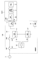
- FIG. 1 is a diagram illustrating an example of a configuration of a charging device 100 according to a first embodiment which is an aspect of the present invention.
- FIG. 2 is a diagram illustrating an example of the configuration of the charging apparatus 100 according to the first embodiment which is an aspect of the present invention.
- FIG. 1 and 2 are diagrams showing an example of the configuration of the charging apparatus 100 according to the first embodiment which is an aspect of the present invention.
- FIG. 1 shows an example in which a vehicle (mode 2/3 vehicle) 101A having a control pilot circuit CON is connected to the charging apparatus 100.
- FIG. 2 shows an example in which a vehicle (mode 1 vehicle) 101B not having the control pilot circuit CON is connected to the charging apparatus 100.
- 1 includes a vehicle inlet IN, an in-vehicle charger (AC / DC) X that converts alternating current into direct current, a battery B, and a control pilot circuit CON that controls charging of the battery B.
- AC / DC in-vehicle charger
- the vehicle 101B shown in FIG. 2 includes a vehicle inlet IN, an in-vehicle charger (AC / DC) X that converts alternating current into direct current, and a battery B.
- AC / DC in-vehicle charger
- the charging device 100 is for charging a battery B loaded on vehicles 101A and 101B.
- the charging device 100 includes a first leakage breaker SW1, a second leakage breaker SW2, a charging cable CA, a charging connector CN, a charging controller C1, an authentication controller C2, an input device ID, a leakage current A cutoff control circuit GC.
- the first earth leakage interrupting means SW1 is connected at one end to the AC power source V.
- the first earth leakage breaking means SW1 conducts between one end and the other end of the first earth leakage breaking means SW1 in the conducting state, and one end of the first earth leakage breaking means SW1 and the other in the breaking state. Block between the edges.
- the first earth leakage cutoff means SW1 enters an interruption state in which an electric leakage interruption control signal SC1 that regulates the interruption of the first earth leakage interruption means SW1 is inputted.
- the first earth leakage breaking means SW1 becomes conductive when the earth leakage breaking control signal SC1 that regulates the conduction of the first earth leakage breaking means SW1 is inputted.
- the first leakage breaker SW1 can be controlled to be in a conductive state or a cut-off state by the user. That is, an operation by the user of the first leakage breaker SW1 is also possible.
- blocking means SW1 is comprised by any of a semiconductor switch, a magnet, a circuit breaker, and a relay, for example.
- the second earth leakage cutoff means SW2 conducts between one end and the other end of the second earth leakage interruption means SW2 in the conduction state, and one end of the second earth leakage interruption means SW2 and the other in the interruption state. Block between the edges.
- blocking means SW2 is comprised by either a semiconductor switch, a magnet, a circuit breaker, and a relay, for example.
- one end of the charging cable CA is connected to the other end of the second leakage breaker SW2.
- the charging connector CN has a first connection terminal T1 connected to the other end of the charging cable CA and a second connection terminal T2 to which a signal is input from the vehicle. It is connected to the connected vehicle inlet IN (via the in-vehicle charger X).
- the first connection terminal T1 of the charging connector CN is connected to the third connection terminal T3 of the vehicle inlet IN when the charging connector CN and the vehicle inlet IN are connected (FIGS. 1 and 2).
- the third connection terminal T3 is connected to the battery B via the in-vehicle charger X.
- the charging current (AC) is supplied from the first connection terminal T1 to the third connection terminal T3
- the in-vehicle charger X converts the charging current from AC to DC and supplies it to the battery B. It has become.
- connection terminal T2 of the charging connector CN is connected to the fourth connection terminal T4 of the vehicle inlet IN when the charging connector CN and the vehicle inlet IN are connected (FIGS. 1 and 2).
- the fourth connection terminal T4 is connected to the control pilot circuit CON.
- the control pilot circuit CON supplies a predetermined signal (a signal including information on permission of charging, connection between the charging connector CN and the vehicle inlet IN, information on the charging voltage of the battery B, etc.) to the fourth connection terminal T4. It is like that.
- this signal is supplied to the charging controller C1 via the second connection terminal T2.
- the fourth connection terminal T4 is connected to a resistor (not shown), for example.
- the voltage of the fourth connection terminal T4 becomes a predetermined voltage, and a predetermined voltage signal is supplied to the second connection terminal T2. This signal is supplied to the charge controller C1 via the second connection terminal T2.
- the charge controller C1 Based on the signal of the second connection terminal T2, the charge controller C1 conducts the second leakage breaker SW2 between the one end and the other end of the second leakage breaker SW2, or the first Control is performed by a control signal SC2 so as to shut off between one end and the other end of the second earth leakage cutoff means SW2.
- the charge controller C1 controls the second leakage breaker SW2 to be in a cut-off state. It is supposed to be.
- the charge controller C1 controls the second leakage breaker SW2 to be in a conductive state. It is supposed to be.
- the charge controller C1 indicates that a signal input from the vehicle 101A (control pilot circuit CON) via the fourth connection terminal T4 and the second connection terminal T2 indicates that the vehicle 101A requests charging. If so, the second leakage breaker SW2 is controlled to be in a conducting state (FIG. 1).
- the charge controller C1 indicates that the signal input from the vehicle 101A (control pilot circuit CON) via the fourth connection terminal T4 and the second connection terminal T2 indicates that the vehicle 101A does not request charging. If so, the second earth leakage interrupting means SW2 is controlled to be in an interrupted state (FIG. 1).
- the charging controller C1 controls the second leakage breaker SW2 to be cut off when the charging of the battery B is completed.
- the charge controller C1 charges the battery B based on a signal input from the vehicle 101A (control pilot circuit CON) via the fourth connection terminal T4 and the second connection terminal T2. Recognize the end of.
- the charge controller C1 recognizes the end of charging of the battery B based on the value of the charging current flowing through the charging cable CA and the charging time, for example.
- the charge controller C1 and the authentication controller C2 can communicate with each other.
- the charge controller C1 detects the operation state of the authentication controller C2, and outputs a first normality confirmation signal S1 corresponding to the operation state of the authentication controller C2.
- the charge controller C1 determines that the second leakage breaker SW2 is uncontrollable, the charge controller C1 defines the breaker state of the first leakage breaker SW1 regardless of the operating state of the authentication controller C2. 1 normality confirmation signal S1 is output.
- the charging controller C1 determines that there is an abnormality in the operation of the authentication controller C2 when there is no predetermined (predefined) response from the authentication controller C2, for example.
- the input device ID allows the user to input authentication information.
- the authentication controller C2 confirms the authentication information input in the input device ID, and when charging the vehicle is permitted, notifies the charging controller C1 of charging permission.
- the charge controller C1 makes the second leakage breaker SW2 conductive only when the authentication controller C2 is notified of the permission of charging.
- the authentication controller C2 detects the operation state of the charge controller C1, and outputs a second normality confirmation signal S2 corresponding to the operation state of the charge controller C1.
- the authentication controller C2 detects the operation state of the charge controller C1, and if there is an abnormality in the operation of the charge controller C1, the authentication controller C2 instructs the charge controller C1 to cut off the second leakage breaker SW2. Yes.
- a normality confirmation signal S2 is output.
- the authentication controller C2 determines that there is an abnormality in the operation of the charge controller C1 when there is no predetermined (predefined) response from the charge controller C1.
- the earth leakage breaking control circuit GC outputs the earth leakage breaking control signal SC1 to the first earth leakage breaking means SW1, thereby connecting the first earth leakage breaking means SW1 between one end and the other end of the first earth leakage breaking means SW1. Is controlled to be in a conductive state in which the first current leakage interrupting means SW1 is disconnected from one end and the other end.
- the earth leakage cutoff control circuit GC outputs the earth leakage interruption control signal SC1 to the first earth leakage interruption means SW1 based on the first normality confirmation signal S1 and the second normality confirmation signal S2. Yes.
- the earth leakage cutoff control circuit GC is configured such that the first normality confirmation signal S1 indicates an abnormal operation of the authentication controller C2, or the second normality confirmation signal S2 indicates an abnormal operation of the charge controller C1.
- a leakage break control signal SC1 that regulates the break of the first leakage breaker SW1 is output to the first leakage breaker SW1.
- the earth leakage cutoff control circuit GC at least provides the earth leakage interruption that regulates the interruption of the first earth leakage breaking means SW1 in accordance with the first normality confirmation signal S1 that defines the interruption state of the first earth leakage interruption means SW1.
- a control signal SC1 is output.
- the earth leakage cutoff control circuit GC indicates that when the battery B is charged, the first normality confirmation signal S1 indicates that there is no abnormality in the operation of the authentication controller C2, and the second normality confirmation signal S2 is charged.
- an electric leakage interruption control signal SC1 that regulates the conduction of the first electric leakage interruption means SW1 is output to the first electric leakage interruption means SW1.
- the earth leakage cutoff control circuit GC is composed of an AND circuit as shown in FIGS. 1 and 2, for example.
- the AND circuit receives the first normality confirmation signal S1 and the second normality confirmation signal S2, and the result of ANDing the first normality confirmation signal S1 and the second normality confirmation signal S2. Is output as a leakage prevention control signal SC1.
- the first normality confirmation signal S1 indicating abnormality of the operation of the authentication controller C2 and the second normality confirmation signal S2 indicating abnormality of the operation of the charge controller C1 are “Low” level, that is, logic “0”. ”Signal.
- the first normality confirmation signal S1 indicating normal operation of the authentication controller C2 and the second normality confirmation signal S2 indicating normal operation of the charge controller C1 are “High” level, that is, logic “1”. Defined by the signal.
- the earth leakage cutoff control signal SC1 is “ It becomes a Low level signal, that is, a logic “0” signal.
- the first leakage breaker SW1 enters a break state.
- the leakage cutoff control signal SC1 is “High” level. That is, the signal is a logic “1”.
- the first leakage breaker SW1 becomes conductive.
- an earth leakage interruption control signal SC1 that regulates interruption of the first earth leakage breaking means SW1 is output to the first earth leakage interruption means SW1.
- the authentication controller C2 detects the operation state of the charge controller C1, and if there is an abnormality in the operation of the charge controller C1, instructs the charge controller C1 to cut off the second leakage breaker SW2.
- a normality confirmation signal S2 is output.
- the charge controller C1 determines that the second leakage breaker SW2 is uncontrollable, the charge controller C1 defines the first leakage breaker SW1 breaker state regardless of the operation state of the authentication controller C2. 1 normality confirmation signal S1 is output.
- the earth leakage cutoff control circuit GC responds to the first normality confirmation signal S1 that defines the interruption state of the first earth leakage interruption means SW1, and the earth leakage interruption control signal that regulates the interruption of the first earth leakage interruption means SW1. SC1 is output.
- the first leakage breaker SW1 can be controlled to stop charging. For example, when the charging voltage of the battery B reaches the target voltage, the charging can be stopped by the first leakage breaker SW1 even if the second leakage breaker SW2 is uncontrollable.
- the charge controller C1 controls the second leakage breaker SW2 to the cut-off state when the signal of the second connection terminal T2 defines that the vehicle inlet IN and the charge connector CN are not connected. To do.
- the charging current is cut off by the second leakage breaker SW2, and the voltage of the first connection terminal T1 of the charging connector CN rises more than necessary. Can be suppressed. The safety of the user can be improved.
- the charge controller C1 controls the second leakage breaker SW2 to be in a conductive state. It is supposed to be.
- the charging current output from the AC power source V is supplied to the third connection terminal T3 (vehicle) via the first and second leakage breakers SW1 and SW2 and the first connection terminal T1 (charging connector CN). Inlet IN).
- the charge controller C1 When the vehicle inlet IN of the vehicle 101A is connected to the charging connector CN, the charge controller C1 inputs from the vehicle 101A (control pilot circuit CON) via the fourth connection terminal T4 and the second connection terminal T2. If the received signal indicates that the vehicle 101A is requesting charging, the second leakage breaker SW2 is controlled to be in a conducting state (FIG. 1).
- the charge controller C1 inputs from the vehicle 101A (control pilot circuit CON) via the fourth connection terminal T4 and the second connection terminal T2. If the received signal indicates that the vehicle 101A does not request charging, the second earth leakage blocking means SW2 is controlled to be in a blocking state (FIG. 1).
- the charging device 100 is the charging device 100 for charging the battery B loaded on the vehicle, and the first leakage having one end connected to the AC power supply V.
- the interruption means SW1, the second earth leakage interruption means SW2 (relay) having one end connected to the other end of the first earth leakage interruption means SW1, and the charge having one end connected to the other end of the second earth leakage interruption means SW2. It has a cable CA, a first connection terminal T1 connected to the other end of the charging cable CA, and a second connection terminal T2 to which a signal is input from the vehicle.
- the second earth leakage blocking means SW2 is One end of earth leakage breaker SW2 and other The charging controller C1 to be controlled, and an input device for inputting authentication information by the user.
- the authentication controller C2 for notifying the charging controller C1 of the charging permission and the earth leakage cutoff control signal SC1 By outputting to the earth leakage breaker SW1, the first earth leakage breaker SW1 is connected to one end and the other end of the first earth leakage breaker SW1, or the first earth leakage breaker SW1
- An earth leakage cut-off control circuit GC for controlling in a cut-off state in which the gap between one end and the other end is cut off.
- the charge controller C1 and the authentication controller C2 can communicate with each other, and the charge controller C1 detects the operation state of the authentication controller C2, and outputs a first normality confirmation signal S1 corresponding to the operation state of the authentication controller C2.
- the authentication controller C2 detects the operation state of the charge controller C1, outputs a second normality confirmation signal S2 corresponding to the operation state of the charge controller C1, and the leakage cutoff control circuit GC outputs the first normality Based on the nature confirmation signal S1 and the second normality confirmation signal S2, the earth leakage interruption control signal SC1 is output to the first earth leakage interruption means SW1.
- the earth leakage cutoff control circuit GC is used when the first normality confirmation signal S1 indicates an abnormality in the operation of the authentication controller C2 or the second normality confirmation signal S2 indicates an abnormality in the operation of the charge controller C1.
- Outputs to the first leakage breaker SW1 a leakage breaker control signal SC1 that defines the breakage of the first leakage breaker SW1.
- the charging controller C1 and the authentication controller C2 maintain mutual normality by constantly confirming each other, and when each normality cannot be confirmed, the first leakage breaker SW1 is controlled to be in a cut-off state. Is done.
- the first earth leakage breaker SW1 can be forcibly cut off.
- the charging device 100 according to the present invention can improve its safety.
Landscapes
- Engineering & Computer Science (AREA)
- Power Engineering (AREA)
- Transportation (AREA)
- Mechanical Engineering (AREA)
- Life Sciences & Earth Sciences (AREA)
- Sustainable Development (AREA)
- Sustainable Energy (AREA)
- Charge And Discharge Circuits For Batteries Or The Like (AREA)
- Emergency Protection Circuit Devices (AREA)
- Electric Propulsion And Braking For Vehicles (AREA)
Abstract
充電装置において、充電コントローラと認証コントローラとは、通信可能になっている。充電コントローラは、認証コントローラの動作状態を検出し、認証コントローラの動作状態に応じた第1の正常性確認信号を出力する。認証コントローラは、充電コントローラの動作状態を検出し、充電コントローラの動作状態に応じた第2の正常性確認信号を出力する。漏電遮断制御回路は、第1および第2の正常性確認信号に基づいて、漏電遮断制御信号を第1の漏電遮断手段に出力する。
Description
本発明は、充電装置、および、充電装置の正常性確認方法に関する発明である。
従来の充電装置は、例えば、交流電源からの交流電圧を漏電ブレーカとリレーとを介して充電コネクタに供給するようになっている。
漏電ブレーカは、使用者が手動で導通状態または遮断状態に切り替えられるようになっている。また、リレーは、充電装置に備えられた充電コントローラ(CPU)が導通状態または遮断状態に制御するようになっている(例えば、特開2011-72104号公報、特開2011-254642号公報参照。)。
しかし、上記従来の充電装置では、例えば、充電コントローラが故障した場合、リレーの制御が不能になり、充電コネクタの電圧が必要以上に上昇したりする問題がある。
本発明の一態様に係る実施例に従った充電装置は、
車両に積載されている電池を充電するための充電装置であって、
交流電源に一端が接続された第1の漏電遮断手段と、
前記第1の漏電遮断手段の他端に一端が接続された第2の漏電遮断手段と、
前記第2の漏電遮断手段の他端に一端が接続された充電ケーブルと、
前記充電ケーブルの他端に接続された第1の接続端子、および、前記車両から信号が入力される第2の接続端子を有し、前記電池の充電時に、前記電池に接続された車両インレットに、接続されるようになっている充電コネクタと、
前記第2の接続端子の信号に基づいて、前記第2の漏電遮断手段を、前記第2の漏電遮断手段の一端と他端との間を導通する導通状態、または、前記第2の漏電遮断手段の一端と他端との間を遮断する遮断状態に、制御する充電コントローラと、
使用者が認証情報を入力する入力装置と、
前記入力装置に入力された認証情報を確認し、車両に対する充電を許可する場合には、前記充電コントローラに充電の許可を通知する認証コントローラと、
漏電遮断制御信号を前記第1の漏電遮断手段に出力することにより、前記第1の漏電遮断手段を、前記第1の漏電遮断手段の一端と他端との間を導通する導通状態、または、前記第1の漏電遮断手段の一端と他端との間を遮断する遮断状態に、制御する漏電遮断制御回路と、を備え、
前記充電コントローラと前記認証コントローラとは、通信可能になっており、
前記充電コントローラは、
前記認証コントローラの動作状態を検出し、前記認証コントローラの動作状態に応じた第1の正常性確認信号を出力し、
前記認証コントローラは、
前記充電コントローラの動作状態を検出し、前記充電コントローラの動作状態に応じた第2の正常性確認信号を出力し、
前記漏電遮断制御回路は、
前記第1の正常性確認信号と前記第2の正常性確認信号とに基づいて、前記漏電遮断制御信号を前記第1の漏電遮断手段に出力する
ことを特徴とする。
車両に積載されている電池を充電するための充電装置であって、
交流電源に一端が接続された第1の漏電遮断手段と、
前記第1の漏電遮断手段の他端に一端が接続された第2の漏電遮断手段と、
前記第2の漏電遮断手段の他端に一端が接続された充電ケーブルと、
前記充電ケーブルの他端に接続された第1の接続端子、および、前記車両から信号が入力される第2の接続端子を有し、前記電池の充電時に、前記電池に接続された車両インレットに、接続されるようになっている充電コネクタと、
前記第2の接続端子の信号に基づいて、前記第2の漏電遮断手段を、前記第2の漏電遮断手段の一端と他端との間を導通する導通状態、または、前記第2の漏電遮断手段の一端と他端との間を遮断する遮断状態に、制御する充電コントローラと、
使用者が認証情報を入力する入力装置と、
前記入力装置に入力された認証情報を確認し、車両に対する充電を許可する場合には、前記充電コントローラに充電の許可を通知する認証コントローラと、
漏電遮断制御信号を前記第1の漏電遮断手段に出力することにより、前記第1の漏電遮断手段を、前記第1の漏電遮断手段の一端と他端との間を導通する導通状態、または、前記第1の漏電遮断手段の一端と他端との間を遮断する遮断状態に、制御する漏電遮断制御回路と、を備え、
前記充電コントローラと前記認証コントローラとは、通信可能になっており、
前記充電コントローラは、
前記認証コントローラの動作状態を検出し、前記認証コントローラの動作状態に応じた第1の正常性確認信号を出力し、
前記認証コントローラは、
前記充電コントローラの動作状態を検出し、前記充電コントローラの動作状態に応じた第2の正常性確認信号を出力し、
前記漏電遮断制御回路は、
前記第1の正常性確認信号と前記第2の正常性確認信号とに基づいて、前記漏電遮断制御信号を前記第1の漏電遮断手段に出力する
ことを特徴とする。
前記充電装置において、
前記漏電遮断制御回路は、
前記第1の正常性確認信号が前記認証コントローラの動作の異常を示す場合、または、前記第2の正常性確認信号が前記充電コントローラの動作の異常を示す場合には、前記第1の漏電遮断手段の遮断を規定する前記漏電遮断制御信号を前記第1の漏電遮断手段に出力する
ことを特徴とする。
前記漏電遮断制御回路は、
前記第1の正常性確認信号が前記認証コントローラの動作の異常を示す場合、または、前記第2の正常性確認信号が前記充電コントローラの動作の異常を示す場合には、前記第1の漏電遮断手段の遮断を規定する前記漏電遮断制御信号を前記第1の漏電遮断手段に出力する
ことを特徴とする。
前記充電装置において、
前記認証コントローラは、
前記充電コントローラの動作状態を検出し、前記充電コントローラの動作に異常がある場合には、前記充電コントローラに前記第2の漏電遮断手段の遮断を指示する
ことを特徴とする。
前記認証コントローラは、
前記充電コントローラの動作状態を検出し、前記充電コントローラの動作に異常がある場合には、前記充電コントローラに前記第2の漏電遮断手段の遮断を指示する
ことを特徴とする。
前記充電装置において、
前記認証コントローラは、
前記充電コントローラに前記第2の漏電遮断手段の遮断を指示しても、前記充電コントローラから前記指示に対する応答が無い場合は、前記充電コントローラの動作の異常を示す前記第2の正常性確認信号を出力する
ことを特徴とする。
前記認証コントローラは、
前記充電コントローラに前記第2の漏電遮断手段の遮断を指示しても、前記充電コントローラから前記指示に対する応答が無い場合は、前記充電コントローラの動作の異常を示す前記第2の正常性確認信号を出力する
ことを特徴とする。
前記充電装置において、
前記充電コントローラは、
前記第2の漏電遮断手段が制御不能であると判断した場合には、前記認証コントローラの動作状態に拘わらず、前記第1の漏電遮断手段の遮断状態を規定する前記第1の正常性確認信号を出力し、
前記漏電遮断制御回路は、
前記第1の漏電遮断手段の遮断状態を規定する前記第1の正常性確認信号に応じて、前記第1の漏電遮断手段の遮断を規定する前記漏電遮断制御信号を出力する
ことを特徴とする。
前記充電コントローラは、
前記第2の漏電遮断手段が制御不能であると判断した場合には、前記認証コントローラの動作状態に拘わらず、前記第1の漏電遮断手段の遮断状態を規定する前記第1の正常性確認信号を出力し、
前記漏電遮断制御回路は、
前記第1の漏電遮断手段の遮断状態を規定する前記第1の正常性確認信号に応じて、前記第1の漏電遮断手段の遮断を規定する前記漏電遮断制御信号を出力する
ことを特徴とする。
前記充電装置において、
前記漏電遮断制御回路は、
前記電池の充電時において、前記第1の正常性確認信号が前記認証コントローラの動作に異常がないことを示し、且つ、前記第2の正常性確認信号が前記充電コントローラの動作に異常が無いことを示す場合には、前記第1の漏電遮断手段の導通を規定する前記漏電遮断制御信号を前記第1の漏電遮断手段に出力する
ことを特徴とする。
前記漏電遮断制御回路は、
前記電池の充電時において、前記第1の正常性確認信号が前記認証コントローラの動作に異常がないことを示し、且つ、前記第2の正常性確認信号が前記充電コントローラの動作に異常が無いことを示す場合には、前記第1の漏電遮断手段の導通を規定する前記漏電遮断制御信号を前記第1の漏電遮断手段に出力する
ことを特徴とする。
前記充電装置において、
前記充電コントローラは、
前記認証コントローラから充電の許可を通知された場合にのみ、前記第2の漏電遮断手段を導通状態にする
ことを特徴とする。
前記充電コントローラは、
前記認証コントローラから充電の許可を通知された場合にのみ、前記第2の漏電遮断手段を導通状態にする
ことを特徴とする。
前記充電装置において、
前記充電コントローラは、
前記認証コントローラから所定の応答が無い場合には、前記認証コントローラの動作に異常があると判断し、
また、前記認証コントローラは、
前記充電コントローラから所定の応答が無い場合には、前記充電コントローラの動作に異常があると判断する
ことを特徴とする。
前記充電コントローラは、
前記認証コントローラから所定の応答が無い場合には、前記認証コントローラの動作に異常があると判断し、
また、前記認証コントローラは、
前記充電コントローラから所定の応答が無い場合には、前記充電コントローラの動作に異常があると判断する
ことを特徴とする。
前記充電装置において、
前記充電コントローラは、
前記第2の接続端子の信号が、前記車両インレットと前記充電コネクタとが接続されていないことを規定する場合には、前記第2の漏電遮断手段を遮断状態に制御する
ことを特徴とする。
前記充電コントローラは、
前記第2の接続端子の信号が、前記車両インレットと前記充電コネクタとが接続されていないことを規定する場合には、前記第2の漏電遮断手段を遮断状態に制御する
ことを特徴とする。
前記充電装置において、
前記充電コントローラは、
前記車両から前記第2の接続端子を介して入力された信号が、前記車両が充電を要求していることを示している場合には、前記第2の漏電遮断手段を導通状態に制御し、
一方、前記車両から前記第2の接続端子を介して入力された信号が、前記車両が充電を要求していないことを示している場合には、前記第2の漏電遮断手段を遮断状態に制御する
ことを特徴とする。
前記充電コントローラは、
前記車両から前記第2の接続端子を介して入力された信号が、前記車両が充電を要求していることを示している場合には、前記第2の漏電遮断手段を導通状態に制御し、
一方、前記車両から前記第2の接続端子を介して入力された信号が、前記車両が充電を要求していないことを示している場合には、前記第2の漏電遮断手段を遮断状態に制御する
ことを特徴とする。
前記充電装置において、
前記充電コントローラは、
前記電池の充電が終了した場合には、前記第2の漏電遮断手段を遮断状態に制御することを特徴とする。
前記充電コントローラは、
前記電池の充電が終了した場合には、前記第2の漏電遮断手段を遮断状態に制御することを特徴とする。
前記充電装置において、
前記第1の漏電遮断手段は、
使用者により導通状態または遮断状態に制御可能であることを特徴とする。
前記第1の漏電遮断手段は、
使用者により導通状態または遮断状態に制御可能であることを特徴とする。
前記充電装置において、
前記第1の漏電遮断手段は、
前記第1の漏電遮断手段の遮断を規定する前記漏電遮断制御信号が入力された場合には、遮断状態になり、
一方、前記第1の漏電遮断手段の導通を規定する前記漏電遮断制御信号が入力された場合には、導通状態になる
ことを特徴とする。
前記第1の漏電遮断手段は、
前記第1の漏電遮断手段の遮断を規定する前記漏電遮断制御信号が入力された場合には、遮断状態になり、
一方、前記第1の漏電遮断手段の導通を規定する前記漏電遮断制御信号が入力された場合には、導通状態になる
ことを特徴とする。
前記充電装置において、
前記第1および第2の漏電遮断手段は、半導体スイッチ、マグネット、遮断機、リレーのいずれかで構成されていることを特徴とする。
前記第1および第2の漏電遮断手段は、半導体スイッチ、マグネット、遮断機、リレーのいずれかで構成されていることを特徴とする。
前記充電装置において、
前記漏電遮断制御回路は、
前記第1の正常性確認信号と前記第2の正常性確認信号とが入力され、前記第1の正常性確認信号と前記第2の正常性確認信号とをAND演算した結果を前記漏電遮断制御信号として出力するAND回路である
ことを特徴とする。
前記漏電遮断制御回路は、
前記第1の正常性確認信号と前記第2の正常性確認信号とが入力され、前記第1の正常性確認信号と前記第2の正常性確認信号とをAND演算した結果を前記漏電遮断制御信号として出力するAND回路である
ことを特徴とする。
本発明の一態様に係る実施例に従った充電装置の正常性確認方法は、
車両に積載されている電池を充電するための充電装置であって、交流電源に一端が接続された第1の漏電遮断手段と、前記第1の漏電遮断手段の他端に一端が接続された第2の漏電遮断手段と、前記第2の漏電遮断手段の他端に一端が接続された充電ケーブルと、前記充電ケーブルの他端に接続された第1の接続端子、および、前記車両から信号が入力される第2の接続端子を有し、前記電池の充電時に、前記電池に接続された車両インレットに、接続されるようになっている充電コネクタと、前記第2の接続端子の信号に基づいて、前記第2の漏電遮断手段を、前記第2の漏電遮断手段の一端と他端との間を導通する導通状態、または、前記第2の漏電遮断手段の一端と他端との間を遮断する遮断状態に、制御する充電コントローラと、使用者が認証情報を入力する入力装置と、前記入力装置に入力された認証情報を確認し、車両に対する充電を許可する場合には、前記充電コントローラに充電の許可を通知する認証コントローラと、漏電遮断制御信号を前記第1の漏電遮断手段に出力することにより、前記第1の漏電遮断手段を、前記第1の漏電遮断手段の一端と他端との間を導通する導通状態、または、前記第1の漏電遮断手段の一端と他端との間を遮断する遮断状態に、制御する漏電遮断制御回路と、を備えた充電装置の正常性確認方法であって、
前記充電コントローラと前記認証コントローラとは、通信可能になっており、
前記充電コントローラは、
前記認証コントローラの動作状態を検出し、前記認証コントローラの動作状態に応じた第1の正常性確認信号を出力し、
前記認証コントローラは、
前記充電コントローラの動作状態を検出し、前記充電コントローラの動作状態に応じた第2の正常性確認信号を出力し、
前記漏電遮断制御回路は、
前記第1の正常性確認信号と前記第2の正常性確認信号とに基づいて、前記漏電遮断制御信号を前記第1の漏電遮断手段に出力する
ことを特徴とする。
車両に積載されている電池を充電するための充電装置であって、交流電源に一端が接続された第1の漏電遮断手段と、前記第1の漏電遮断手段の他端に一端が接続された第2の漏電遮断手段と、前記第2の漏電遮断手段の他端に一端が接続された充電ケーブルと、前記充電ケーブルの他端に接続された第1の接続端子、および、前記車両から信号が入力される第2の接続端子を有し、前記電池の充電時に、前記電池に接続された車両インレットに、接続されるようになっている充電コネクタと、前記第2の接続端子の信号に基づいて、前記第2の漏電遮断手段を、前記第2の漏電遮断手段の一端と他端との間を導通する導通状態、または、前記第2の漏電遮断手段の一端と他端との間を遮断する遮断状態に、制御する充電コントローラと、使用者が認証情報を入力する入力装置と、前記入力装置に入力された認証情報を確認し、車両に対する充電を許可する場合には、前記充電コントローラに充電の許可を通知する認証コントローラと、漏電遮断制御信号を前記第1の漏電遮断手段に出力することにより、前記第1の漏電遮断手段を、前記第1の漏電遮断手段の一端と他端との間を導通する導通状態、または、前記第1の漏電遮断手段の一端と他端との間を遮断する遮断状態に、制御する漏電遮断制御回路と、を備えた充電装置の正常性確認方法であって、
前記充電コントローラと前記認証コントローラとは、通信可能になっており、
前記充電コントローラは、
前記認証コントローラの動作状態を検出し、前記認証コントローラの動作状態に応じた第1の正常性確認信号を出力し、
前記認証コントローラは、
前記充電コントローラの動作状態を検出し、前記充電コントローラの動作状態に応じた第2の正常性確認信号を出力し、
前記漏電遮断制御回路は、
前記第1の正常性確認信号と前記第2の正常性確認信号とに基づいて、前記漏電遮断制御信号を前記第1の漏電遮断手段に出力する
ことを特徴とする。
本発明に係る充電装置は、車両に積載されている電池を充電するための充電装置であって、交流電源に一端が接続された第1の漏電遮断手段と、第1の漏電遮断手段の他端に一端が接続された第2の漏電遮断手段と、第2の漏電遮断手段の他端に一端が接続された充電ケーブルと、充電ケーブルの他端に接続された第1の接続端子、および、車両から信号が入力される第2の接続端子を有し、電池の充電時に、電池に(車載充電器を介して)接続された車両インレットに、接続されるようになっている充電コネクタと、第2の接続端子の信号に基づいて、第2の漏電遮断手段を、第2の漏電遮断手段の一端と他端との間を導通する導通状態、または、第2の漏電遮断手段の一端と他端との間を遮断する遮断状態に、制御する充電コントローラと、使用者が認証情報を入力する入力装置と、入力装置に入力された認証情報を確認し、車両に対する充電を許可する場合には、充電コントローラに充電の許可を通知する認証コントローラと、漏電遮断制御信号を第1の漏電遮断手段に出力することにより、第1の漏電遮断手段を、第1の漏電遮断手段の一端と他端との間を導通する導通状態、または、第1の漏電遮断手段の一端と他端との間を遮断する遮断状態に、制御する漏電遮断制御回路と、を備える。
充電コントローラと認証コントローラとは、通信可能になっており、充電コントローラは、認証コントローラの動作状態を検出し、認証コントローラの動作状態に応じた第1の正常性確認信号を出力し、認証コントローラは、充電コントローラの動作状態を検出し、充電コントローラの動作状態に応じた第2の正常性確認信号を出力し、漏電遮断制御回路は、第1の正常性確認信号と第2の正常性確認信号とに基づいて、漏電遮断制御信号を第1の漏電遮断手段に出力する。
特に、漏電遮断制御回路は、第1の正常性確認信号が認証コントローラの動作の異常を示し、または、第2の正常性確認信号が充電コントローラの動作の異常を示す場合には、第1の漏電遮断手段の遮断を規定する漏電遮断制御信号を第1の漏電遮断手段に出力する。
このように、充電コントローラと認証コントローラが、常時相互確認することで互いの正常性を維持し、各々の正常性が確認できない場合には、第1の漏電遮断手段が遮断状態に制御される。
これにより、充電コントローラと認証コントローラとの少なくとも何れか一方が故障した場合に、第1の漏電遮断手段を強制的に遮断状態にできる。
すなわち、充電コントローラと認証コントローラとの少なくとも何れか一方が故障した場合に、充電コネクタには交流電流が供給されないため、充電コネクタの電圧が必要以上に上昇するのを抑制することができる。したがって、本発明に係る充電装置は、その安全性を向上することができる。
以下、本発明に係る各実施例について図面に基づいて説明する。
図1および図2は、本発明の一態様である実施例1に係る充電装置100の構成の一例を示す図である。なお、図1は、充電装置100にコントロールパイロット回路CONを有する車両(モード2/3車両)101Aが接続されている例を示す。また、図2は、充電装置100にコントロールパイロット回路CONを有さない車両(モード1車両)101Bが接続されている例を示す。
図1に示す車両101Aは、車両インレットINと、交流を直流に変換する車載充電器(AC/DC)Xと、電池Bと、電池Bの充電を制御するコントロールパイロット回路CONと、を備える。
また、図2に示す車両101Bは、車両インレットINと、交流を直流に変換する車載充電器(AC/DC)Xと、電池Bと、を備える。
図1および図2に示すように、充電装置100は、車両101A、101Bに積載されている電池Bを充電するためのものである。
この充電装置100は、第1の漏電遮断手段SW1と、第2の漏電遮断手段SW2と、充電ケーブルCAと、充電コネクタCNと、充電コントローラC1と、認証コントローラC2と、入力装置IDと、漏電遮断制御回路GCと、を備える。
第1の漏電遮断手段SW1は、交流電源Vに一端が接続されている。
この第1の漏電遮断手段SW1は、導通状態において、第1の漏電遮断手段SW1の一端と他端との間を導通し、また、遮断状態において、第1の漏電遮断手段SW1の一端と他端との間を遮断する。
例えば、第1の漏電遮断手段SW1は、第1の漏電遮断手段SW1の遮断を規定する漏電遮断制御信号SC1が入力された場合には、遮断する遮断状態になる。
一方、第1の漏電遮断手段SW1は、第1の漏電遮断手段SW1の導通を規定する漏電遮断制御信号SC1が入力された場合には、導通状態になる。
なお、第1の漏電遮断手段SW1は、使用者により導通状態または遮断状態に制御可能になっている。すなわち、第1の漏電遮断手段SW1の使用者による操作も可能である。
なお、この第1の漏電遮断手段SW1は、例えば、半導体スイッチ、マグネット、遮断機、リレーのいずれかで構成される。
また、第2の漏電遮断手段SW2は、第1の漏電遮断手段SW1の他端に一端が接続されている。この第2の漏電遮断手段SW2は、導通状態において、第2の漏電遮断手段SW2の一端と他端との間を導通し、また、遮断状態において、第2の漏電遮断手段SW2の一端と他端との間を遮断する。
なお、この第2の漏電遮断手段SW2は、例えば、半導体スイッチ、マグネット、遮断機、リレーのいずれかで構成される。
また、充電ケーブルCAは、第2の漏電遮断手段SW2の他端に一端が接続されている。
充電コネクタCNは、充電ケーブルCAの他端に接続された第1の接続端子T1、および、車両から信号が入力される第2の接続端子T2を有し、電池Bの充電時に、電池Bに(車載充電器Xを介して)接続された車両インレットINに、接続されるようになっている。
この充電コネクタCNの第1の接続端子T1は、充電コネクタCNと車両インレットINとが接続されたとき、車両インレットINの第3の接続端子T3に接続される(図1、図2)。
この第3の接続端子T3は、車載充電器Xを介して、電池Bに接続されている。充電電流(交流)が、第1の接続端子T1からこの第3の接続端子T3に供給されると、車載充電器Xが充電電流を交流から直流に変換して、電池Bに供給するようになっている。
また、充電コネクタCNの第2の接続端子T2は、充電コネクタCNと車両インレットINとが接続されたとき、車両インレットINの第4の接続端子T4に接続される(図1、図2)。
図1の例では、第4の接続端子T4は、コントロールパイロット回路CONに接続されている。このコントロールパイロット回路CONから第4の接続端子T4に所定の信号(充電の許可、充電コネクタCNと車両インレットINとの接続に関する情報、電池Bの充電電圧の情報等を含む信号)が供給されるようになっている。充電コネクタCNと車両インレットINとが接続されると、この信号が第2の接続端子T2を介して充電コントローラC1に供給されるようになっている。
また、図2の例では、第4の接続端子T4は、例えば、図示しない抵抗に接続されている。充電コネクタCNと車両インレットINとが接続されると、この第4の接続端子T4の電圧が所定の電圧になり、第2の接続端子T2に所定の電圧信号が供給される。この信号が第2の接続端子T2を介して充電コントローラC1に供給されるようになっている。
充電コントローラC1は、第2の接続端子T2の信号に基づいて、第2の漏電遮断手段SW2を、第2の漏電遮断手段SW2の一端と他端との間を導通する導通状態、または、第2の漏電遮断手段SW2の一端と他端との間を遮断する遮断状態に、制御信号SC2により制御するようになっている。
例えば、充電コントローラC1は、第2の接続端子T2の信号が、車両インレットINと充電コネクタCNとが接続されていないことを規定する場合には、第2の漏電遮断手段SW2を遮断状態に制御するようになっている。
一方、充電コントローラC1は、第2の接続端子T2の信号が、車両インレットINと充電コネクタCNとが接続されていることを規定する場合には、第2の漏電遮断手段SW2を導通状態に制御するようになっている。
また、充電コントローラC1は、車両101A(コントロールパイロット回路CON)から第4の接続端子T4および第2の接続端子T2を介して入力された信号が、車両101Aが充電を要求していることを示している場合には、第2の漏電遮断手段SW2を導通状態に制御するようになっている(図1)。
一方、充電コントローラC1は、車両101A(コントロールパイロット回路CON)から第4の接続端子T4および第2の接続端子T2を介して入力された信号が、車両101Aが充電を要求していないことを示している場合には、第2の漏電遮断手段SW2を遮断状態に制御するようになっている(図1)。
なお、充電コントローラC1は、電池Bの充電が終了した場合には、第2の漏電遮断手段SW2を遮断状態に制御するようになっている。
図1の例では、充電コントローラC1は、例えば、車両101A(コントロールパイロット回路CON)から第4の接続端子T4および第2の接続端子T2を介して入力された信号に基づいて、電池Bの充電の終了を認識する。
また、図2の例では、充電コントローラC1は、例えば、充電ケーブルCAに流れる充電電流の値と充電時間に基づいて、電池Bの充電の終了を認識する。
ここで、充電コントローラC1と認証コントローラC2とは、通信可能になっている。
そして、充電コントローラC1は、認証コントローラC2の動作状態を検出し、認証コントローラC2の動作状態に応じた第1の正常性確認信号S1を出力するようになっている。
特に、充電コントローラC1は、第2の漏電遮断手段SW2が制御不能であると判断した場合には、認証コントローラC2の動作状態に拘わらず、第1の漏電遮断手段SW1の遮断状態を規定する第1の正常性確認信号S1を出力するようになっている。
なお、充電コントローラC1は、例えば、認証コントローラC2から所定の(予め規定された)応答が無い場合には、認証コントローラC2の動作に異常があると判断するようになっている。
入力装置IDは、使用者が認証情報を入力するようになっている。
認証コントローラC2は、入力装置IDに入力された認証情報を確認し、車両に対する充電を許可する場合には、充電コントローラC1に充電の許可を通知するようになっている。そして、充電コントローラC1は、この認証コントローラC2から充電の許可を通知された場合にのみ、第2の漏電遮断手段SW2を導通状態にするようになっている。
また、認証コントローラC2は、充電コントローラC1の動作状態を検出し、充電コントローラC1の動作状態に応じた第2の正常性確認信号S2を出力するようになっている。
例えば、認証コントローラC2は、充電コントローラC1の動作状態を検出し、充電コントローラC1の動作に異常がある場合には、充電コントローラC1に第2の漏電遮断手段SW2の遮断を指示するようになっている。
さらに、認証コントローラC2は、充電コントローラC1に第2の漏電遮断手段SW2の遮断を指示しても、充電コントローラC1から指示に対する応答が無い場合は、充電コントローラC1の動作の異常を示す第2の正常性確認信号S2を出力するようになっている。
なお、認証コントローラC2は、充電コントローラC1から所定の(予め規定された)応答が無い場合には、充電コントローラC1の動作に異常があると判断するようになっている。
漏電遮断制御回路GCは、漏電遮断制御信号SC1を第1の漏電遮断手段SW1に出力することにより、第1の漏電遮断手段SW1を、第1の漏電遮断手段SW1の一端と他端との間を導通する導通状態、または、第1の漏電遮断手段SW1の一端と他端との間を遮断する遮断状態に、制御するようになっている。
この漏電遮断制御回路GCは、第1の正常性確認信号S1と第2の正常性確認信号S2とに基づいて、漏電遮断制御信号SC1を第1の漏電遮断手段SW1に出力するようになっている。
例えば、この漏電遮断制御回路GCは、第1の正常性確認信号S1が認証コントローラC2の動作の異常を示す場合、または、第2の正常性確認信号S2が充電コントローラC1の動作の異常を示す場合には、第1の漏電遮断手段SW1の遮断を規定する漏電遮断制御信号SC1を第1の漏電遮断手段SW1に出力するようになっている。
したがって、漏電遮断制御回路GCは、少なくとも、第1の漏電遮断手段SW1の遮断状態を規定する第1の正常性確認信号S1に応じて、第1の漏電遮断手段SW1の遮断を規定する漏電遮断制御信号SC1を出力する。
なお、漏電遮断制御回路GCは、電池Bの充電時において、第1の正常性確認信号S1が認証コントローラC2の動作に異常がないことを示し、且つ、第2の正常性確認信号S2が充電コントローラC1の動作に異常が無いことを示す場合には、第1の漏電遮断手段SW1の導通を規定する漏電遮断制御信号SC1を第1の漏電遮断手段SW1に出力するようになっている。
この漏電遮断制御回路GCは、例えば、図1、図2に示すように、AND回路で構成される。このAND回路は、第1の正常性確認信号S1と第2の正常性確認信号S2とが入力され、第1の正常性確認信号S1と第2の正常性確認信号S2とをAND演算した結果を漏電遮断制御信号SC1として出力するようになっている。
この場合、認証コントローラC2の動作の異常を示す第1の正常性確認信号S1および充電コントローラC1の動作の異常を示す第2の正常性確認信号S2は、“Low”レベル、すなわち、論理“0”の信号で定義される。
一方、認証コントローラC2の動作の正常を示す第1の正常性確認信号S1および充電コントローラC1の動作の正常を示す第2の正常性確認信号S2は、“High”レベル、すなわち、論理“1”の信号で定義される。
例えば、第1の正常性確認信号S1と第2の正常性確認信号S2との何れか一方が、“Low”レベル、すなわち、論理“0”の信号のとき、漏電遮断制御信号SC1は、“Low”レベル、すなわち、論理“0”の信号となる。この“Low”レベルの漏電遮断制御信号SC1に応じて、第1の漏電遮断手段SW1は遮断状態になる。
一方、第1の正常性確認信号S1と第2の正常性確認信号S2とが、“High”レベル、すなわち、論理“1”の信号のとき、漏電遮断制御信号SC1は、“High”レベル、すなわち、論理“1”の信号となる。この“High”レベルの漏電遮断制御信号SC1に応じて、第1の漏電遮断手段SW1は導通状態になる。
次に、以上のような構成を有する充電装置100の正常性確認方法の一例について、説明する。
例えば、漏電遮断制御回路GCは、第1の正常性確認信号S1が認証コントローラC2の動作の異常を示す場合、または、第2の正常性確認信号S2が充電コントローラC1の動作の異常を示す場合には、第1の漏電遮断手段SW1の遮断を規定する漏電遮断制御信号SC1を第1の漏電遮断手段SW1に出力する。
例えば、認証コントローラC2は、充電コントローラC1の動作状態を検出し、充電コントローラC1の動作に異常がある場合には、充電コントローラC1に第2の漏電遮断手段SW2の遮断を指示する。
これにより、第2の漏電遮断手段SW2が遮断状態に制御されれば、充電が停止される。すなわち、動作状態が異常である充電コントローラC1による充電制御を抑制することができる。
さらに、認証コントローラC2は、充電コントローラC1に第2の漏電遮断手段SW2の遮断を指示しても、充電コントローラC1から指示に対する応答が無い場合は、充電コントローラC1の動作の異常を示す第2の正常性確認信号S2を出力する。
これにより、第1の漏電遮断手段SW1が遮断状態に制御されれば、充電が停止される。すなわち、動作状態が異常である充電コントローラC1による充電制御を、より確実に抑制することができる。
一方、充電コントローラC1は、第2の漏電遮断手段SW2が制御不能であると判断した場合には、認証コントローラC2の動作状態に拘わらず、第1の漏電遮断手段SW1の遮断状態を規定する第1の正常性確認信号S1を出力する。
そして、漏電遮断制御回路GCは、第1の漏電遮断手段SW1の遮断状態を規定する第1の正常性確認信号S1に応じて、第1の漏電遮断手段SW1の遮断を規定する漏電遮断制御信号SC1を出力する。
これにより、第2の漏電遮断手段SW2が制御不能である場合に、第1の漏電遮断手段SW1を制御して、充電を停止させることができる。例えば、電池Bの充電電圧が目標電圧に達した場合に、第2の漏電遮断手段SW2が制御不能であっても、第1の漏電遮断手段SW1により、充電を停止させることができる。
また、充電コントローラC1は、第2の接続端子T2の信号が、車両インレットINと充電コネクタCNとが接続されていないことを規定する場合には、第2の漏電遮断手段SW2を遮断状態に制御する。
これにより、車両インレットINと充電コネクタCNとが接続されていない場合に、第2の漏電遮断手段SW2により充電電流が遮断され、充電コネクタCNの第1の接続端子T1の電圧が必要以上に上昇することを抑制できる。使用者の安全性を向上することができる。
一方、充電コントローラC1は、第2の接続端子T2の信号が、車両インレットINと充電コネクタCNとが接続されていることを規定する場合には、第2の漏電遮断手段SW2を導通状態に制御するようになっている。
これにより、交流電源Vか出力された充電電流が、第1、第2の漏電遮断手段SW1、SW2、第1の接続端子T1(充電コネクタCN)を介して、第3の接続端子T3(車両インレットIN)に供給される。
また、車両101Aの車両インレットINが充電コネクタCNに接続された場合において、充電コントローラC1は、車両101A(コントロールパイロット回路CON)から第4の接続端子T4および第2の接続端子T2を介して入力された信号が、車両101Aが充電を要求していることを示している場合には、第2の漏電遮断手段SW2を導通状態に制御する(図1)。
これにより、車両101Aの電池Bに対する充電が開始される。
一方、車両101Aの車両インレットINが充電コネクタCNに接続された場合において、充電コントローラC1は、車両101A(コントロールパイロット回路CON)から第4の接続端子T4および第2の接続端子T2を介して入力された信号が、車両101Aが充電を要求していないことを示している場合には、第2の漏電遮断手段SW2を遮断状態に制御する(図1)。
これにより、車両101Aが充電を要求していない場合に、充電コネクタCNから充電電流が出力されるのを抑制することができる。
以上のように、本発明の一態様に係る充電装置100は、車両に積載されている電池Bを充電するための充電装置100であって、交流電源Vに一端が接続された第1の漏電遮断手段SW1と、第1の漏電遮断手段SW1の他端に一端が接続された第2の漏電遮断手段SW2(リレー)と、第2の漏電遮断手段SW2の他端に一端が接続された充電ケーブルCAと、充電ケーブルCAの他端に接続された第1の接続端子T1、および、車両から信号が入力される第2の接続端子T2を有し、電池Bの充電時に、電池Bに(車載充電器を介して)接続された車両インレットINに、接続されるようになっている充電コネクタCNと、第2の接続端子T2の信号に基づいて、第2の漏電遮断手段SW2を、第2の漏電遮断手段SW2の一端と他端との間を導通する導通状態、または、第2の漏電遮断手段SW2の一端と他端との間を遮断する遮断状態に、制御する充電コントローラC1と、使用者が認証情報を入力する入力装置IDと、入力装置IDに入力された認証情報を確認し、車両に対する充電を許可する場合には、充電コントローラC1に充電の許可を通知する認証コントローラC2と、漏電遮断制御信号SC1を第1の漏電遮断手段SW1に出力することにより、第1の漏電遮断手段SW1を、第1の漏電遮断手段SW1の一端と他端との間を導通する導通状態、または、第1の漏電遮断手段SW1の一端と他端との間を遮断する遮断状態に、制御する漏電遮断制御回路GCと、を備える。
充電コントローラC1と認証コントローラC2とは、通信可能になっており、充電コントローラC1は、認証コントローラC2の動作状態を検出し、認証コントローラC2の動作状態に応じた第1の正常性確認信号S1を出力し、認証コントローラC2は、充電コントローラC1の動作状態を検出し、充電コントローラC1の動作状態に応じた第2の正常性確認信号S2を出力し、漏電遮断制御回路GCは、第1の正常性確認信号S1と第2の正常性確認信号S2とに基づいて、漏電遮断制御信号SC1を第1の漏電遮断手段SW1に出力する。
特に、漏電遮断制御回路GCは、第1の正常性確認信号S1が認証コントローラC2の動作の異常を示し、または、第2の正常性確認信号S2が充電コントローラC1の動作の異常を示す場合には、第1の漏電遮断手段SW1の遮断を規定する漏電遮断制御信号SC1を第1の漏電遮断手段SW1に出力する。
このように、充電コントローラC1と認証コントローラC2が、常時相互確認することで互いの正常性を維持し、各々の正常性が確認できない場合には、第1の漏電遮断手段SW1が遮断状態に制御される。
これにより、充電コントローラC1と認証コントローラC2との少なくとも何れか一方が故障した場合に、第1の漏電遮断手段SW1を強制的に遮断状態にできる。
すなわち、充電コントローラC1と認証コントローラC2との少なくとも何れか一方が故障した場合に、充電コネクタCNには交流電流が供給されないため、充電コネクタの電圧が必要以上に上昇するのを抑制することができる。
したがって、本発明に係る充電装置100は、その安全性を向上することができる。
なお、実施例は例示であり、発明の範囲はそれらに限定されない。
100 充電装置
101A、101B 車両
V 交流電源
CON コントロールパイロット回路
IN 車両インレット
X 車載充電器(AC/DC)
B 電池B
SW1 第1の漏電遮断手段
SW2 第2の漏電遮断手段
CA 充電ケーブル
CN 充電コネクタ
C1 充電コントローラ
C2 認証コントローラ
ID 入力装置
GC 漏電遮断制御回路
SC1 漏電遮断制御信号
SC2 制御信号
T1 第1の接続端子
T2 第2の接続端子
T3 第3の接続端子
T4 第4の接続端子
101A、101B 車両
V 交流電源
CON コントロールパイロット回路
IN 車両インレット
X 車載充電器(AC/DC)
B 電池B
SW1 第1の漏電遮断手段
SW2 第2の漏電遮断手段
CA 充電ケーブル
CN 充電コネクタ
C1 充電コントローラ
C2 認証コントローラ
ID 入力装置
GC 漏電遮断制御回路
SC1 漏電遮断制御信号
SC2 制御信号
T1 第1の接続端子
T2 第2の接続端子
T3 第3の接続端子
T4 第4の接続端子
Claims (16)
- 車両に積載されている電池を充電するための充電装置であって、
交流電源に一端が接続された第1の漏電遮断手段と、
前記第1の漏電遮断手段の他端に一端が接続された第2の漏電遮断手段と、
前記第2の漏電遮断手段の他端に一端が接続された充電ケーブルと、
前記充電ケーブルの他端に接続された第1の接続端子、および、前記車両から信号が入力される第2の接続端子を有し、前記電池の充電時に、前記電池に接続された車両インレットに、接続されるようになっている充電コネクタと、
前記第2の接続端子の信号に基づいて、前記第2の漏電遮断手段を、前記第2の漏電遮断手段の一端と他端との間を導通する導通状態、または、前記第2の漏電遮断手段の一端と他端との間を遮断する遮断状態に、制御する充電コントローラと、
使用者が認証情報を入力する入力装置と、
前記入力装置に入力された認証情報を確認し、車両に対する充電を許可する場合には、前記充電コントローラに充電の許可を通知する認証コントローラと、
漏電遮断制御信号を前記第1の漏電遮断手段に出力することにより、前記第1の漏電遮断手段を、前記第1の漏電遮断手段の一端と他端との間を導通する導通状態、または、前記第1の漏電遮断手段の一端と他端との間を遮断する遮断状態に、制御する漏電遮断制御回路と、を備え、
前記充電コントローラと前記認証コントローラとは、通信可能になっており、
前記充電コントローラは、
前記認証コントローラの動作状態を検出し、前記認証コントローラの動作状態に応じた第1の正常性確認信号を出力し、
前記認証コントローラは、
前記充電コントローラの動作状態を検出し、前記充電コントローラの動作状態に応じた第2の正常性確認信号を出力し、
前記漏電遮断制御回路は、
前記第1の正常性確認信号と前記第2の正常性確認信号とに基づいて、前記漏電遮断制御信号を前記第1の漏電遮断手段に出力する
ことを特徴とする充電装置。 - 前記漏電遮断制御回路は、
前記第1の正常性確認信号が前記認証コントローラの動作の異常を示す場合、または、前記第2の正常性確認信号が前記充電コントローラの動作の異常を示す場合には、前記第1の漏電遮断手段の遮断を規定する前記漏電遮断制御信号を前記第1の漏電遮断手段に出力する
ことを特徴とする請求項1に記載の充電装置。 - 前記認証コントローラは、
前記充電コントローラの動作状態を検出し、前記充電コントローラの動作に異常がある場合には、前記充電コントローラに前記第2の漏電遮断手段の遮断を指示する
ことを特徴とする請求項2に記載の充電装置。 - 前記認証コントローラは、
前記充電コントローラに前記第2の漏電遮断手段の遮断を指示しても、前記充電コントローラから前記指示に対する応答が無い場合は、前記充電コントローラの動作の異常を示す前記第2の正常性確認信号を出力する
ことを特徴とする請求項3に記載の充電装置。 - 前記充電コントローラは、
前記第2の漏電遮断手段が制御不能であると判断した場合には、前記認証コントローラの動作状態に拘わらず、前記第1の漏電遮断手段の遮断状態を規定する前記第1の正常性確認信号を出力し、
前記漏電遮断制御回路は、
前記第1の漏電遮断手段の遮断状態を規定する前記第1の正常性確認信号に応じて、前記第1の漏電遮断手段の遮断を規定する前記漏電遮断制御信号を出力する
ことを特徴とする請求項2に記載の充電装置。 - 前記漏電遮断制御回路は、
前記電池の充電時において、前記第1の正常性確認信号が前記認証コントローラの動作に異常がないことを示し、且つ、前記第2の正常性確認信号が前記充電コントローラの動作に異常が無いことを示す場合には、前記第1の漏電遮断手段の導通を規定する前記漏電遮断制御信号を前記第1の漏電遮断手段に出力する
ことを特徴とする請求項2に記載の充電装置。 - 前記充電コントローラは、
前記認証コントローラから充電の許可を通知された場合にのみ、前記第2の漏電遮断手段を導通状態にする
ことを特徴とする請求項2に記載の充電装置。 - 前記充電コントローラは、
前記認証コントローラから所定の応答が無い場合には、前記認証コントローラの動作に異常があると判断し、
また、前記認証コントローラは、
前記充電コントローラから所定の応答が無い場合には、前記充電コントローラの動作に異常があると判断する
ことを特徴とする請求項2に記載の充電装置。 - 前記充電コントローラは、
前記第2の接続端子の信号が、前記車両インレットと前記充電コネクタとが接続されていないことを規定する場合には、前記第2の漏電遮断手段を遮断状態に制御する
ことを特徴とする請求項2に記載の充電装置。 - 前記充電コントローラは、
前記車両から前記第2の接続端子を介して入力された信号が、前記車両が充電を要求していることを示している場合には、前記第2の漏電遮断手段を導通状態に制御し、
一方、前記車両から前記第2の接続端子を介して入力された信号が、前記車両が充電を要求していないことを示している場合には、前記第2の漏電遮断手段を遮断状態に制御する
ことを特徴とする請求項2に記載の充電装置。 - 前記充電コントローラは、
前記電池の充電が終了した場合には、前記第2の漏電遮断手段を遮断状態に制御することを特徴とする請求項2に記載の充電装置。 - 前記第1の漏電遮断手段は、
使用者により導通状態または遮断状態に制御可能であることを特徴とする請求項2に記載の充電装置。 - 前記第1の漏電遮断手段は、
前記第1の漏電遮断手段の遮断を規定する前記漏電遮断制御信号が入力された場合には、遮断状態になり、
一方、前記第1の漏電遮断手段の導通を規定する前記漏電遮断制御信号が入力された場合には、導通状態になる
ことを特徴とする請求項2に記載の充電装置。 - 前記第1および第2の漏電遮断手段は、半導体スイッチ、マグネット、遮断機、リレーのいずれかで構成されていることを特徴とする請求項1に記載の充電装置。
- 前記漏電遮断制御回路は、
前記第1の正常性確認信号と前記第2の正常性確認信号とが入力され、前記第1の正常性確認信号と前記第2の正常性確認信号とをAND演算した結果を前記漏電遮断制御信号として出力するAND回路である
ことを特徴とする請求項2に記載の充電装置。 - 車両に積載されている電池を充電するための充電装置であって、交流電源に一端が接続された第1の漏電遮断手段と、前記第1の漏電遮断手段の他端に一端が接続された第2の漏電遮断手段と、前記第2の漏電遮断手段の他端に一端が接続された充電ケーブルと、前記充電ケーブルの他端に接続された第1の接続端子、および、前記車両から信号が入力される第2の接続端子を有し、前記電池の充電時に、前記電池に接続された車両インレットに、接続されるようになっている充電コネクタと、前記第2の接続端子の信号に基づいて、前記第2の漏電遮断手段を、前記第2の漏電遮断手段の一端と他端との間を導通する導通状態、または、前記第2の漏電遮断手段の一端と他端との間を遮断する遮断状態に、制御する充電コントローラと、使用者が認証情報を入力する入力装置と、前記入力装置に入力された認証情報を確認し、車両に対する充電を許可する場合には、前記充電コントローラに充電の許可を通知する認証コントローラと、漏電遮断制御信号を前記第1の漏電遮断手段に出力することにより、前記第1の漏電遮断手段を、前記第1の漏電遮断手段の一端と他端との間を導通する導通状態、または、前記第1の漏電遮断手段の一端と他端との間を遮断する遮断状態に、制御する漏電遮断制御回路と、を備えた充電装置の正常性確認方法であって、
前記充電コントローラと前記認証コントローラとは、通信可能になっており、
前記充電コントローラは、
前記認証コントローラの動作状態を検出し、前記認証コントローラの動作状態に応じた第1の正常性確認信号を出力し、
前記認証コントローラは、
前記充電コントローラの動作状態を検出し、前記充電コントローラの動作状態に応じた第2の正常性確認信号を出力し、
前記漏電遮断制御回路は、
前記第1の正常性確認信号と前記第2の正常性確認信号とに基づいて、前記漏電遮断制御信号を前記第1の漏電遮断手段に出力する
ことを特徴とする充電装置の正常性確認方法。
Priority Applications (2)
| Application Number | Priority Date | Filing Date | Title |
|---|---|---|---|
| PCT/JP2012/083821 WO2014102953A1 (ja) | 2012-12-27 | 2012-12-27 | 充電装置、および、充電装置の正常性確認方法 |
| JP2014525244A JP5819528B2 (ja) | 2012-12-27 | 2012-12-27 | 充電装置、および、充電装置の正常性確認方法 |
Applications Claiming Priority (1)
| Application Number | Priority Date | Filing Date | Title |
|---|---|---|---|
| PCT/JP2012/083821 WO2014102953A1 (ja) | 2012-12-27 | 2012-12-27 | 充電装置、および、充電装置の正常性確認方法 |
Publications (1)
| Publication Number | Publication Date |
|---|---|
| WO2014102953A1 true WO2014102953A1 (ja) | 2014-07-03 |
Family
ID=51020109
Family Applications (1)
| Application Number | Title | Priority Date | Filing Date |
|---|---|---|---|
| PCT/JP2012/083821 Ceased WO2014102953A1 (ja) | 2012-12-27 | 2012-12-27 | 充電装置、および、充電装置の正常性確認方法 |
Country Status (2)
| Country | Link |
|---|---|
| JP (1) | JP5819528B2 (ja) |
| WO (1) | WO2014102953A1 (ja) |
Citations (3)
| Publication number | Priority date | Publication date | Assignee | Title |
|---|---|---|---|---|
| JP2010115087A (ja) * | 2008-11-10 | 2010-05-20 | Makita Corp | 電動工具用充電システム、電動工具用バッテリパック、及び電動工具用充電器 |
| JP2011120359A (ja) * | 2009-12-02 | 2011-06-16 | Toyota Motor Corp | 給電装置、車両および充電システム |
| WO2012169050A1 (ja) * | 2011-06-09 | 2012-12-13 | トヨタ自動車株式会社 | 車両用給電設備 |
-
2012
- 2012-12-27 JP JP2014525244A patent/JP5819528B2/ja active Active
- 2012-12-27 WO PCT/JP2012/083821 patent/WO2014102953A1/ja not_active Ceased
Patent Citations (3)
| Publication number | Priority date | Publication date | Assignee | Title |
|---|---|---|---|---|
| JP2010115087A (ja) * | 2008-11-10 | 2010-05-20 | Makita Corp | 電動工具用充電システム、電動工具用バッテリパック、及び電動工具用充電器 |
| JP2011120359A (ja) * | 2009-12-02 | 2011-06-16 | Toyota Motor Corp | 給電装置、車両および充電システム |
| WO2012169050A1 (ja) * | 2011-06-09 | 2012-12-13 | トヨタ自動車株式会社 | 車両用給電設備 |
Also Published As
| Publication number | Publication date |
|---|---|
| JP5819528B2 (ja) | 2015-11-24 |
| JPWO2014102953A1 (ja) | 2017-01-12 |
Similar Documents
| Publication | Publication Date | Title |
|---|---|---|
| US11186191B2 (en) | Charging device for electric vehicle | |
| US10160325B2 (en) | Vehicle power control method and system for jump-start | |
| JP6394631B2 (ja) | 電源装置 | |
| JP5908944B2 (ja) | 電力制御装置 | |
| JP6174641B2 (ja) | 車両充電装置及び充電方法 | |
| US9481324B2 (en) | Vehicle battery charger | |
| JP6614452B2 (ja) | リレー装置 | |
| KR20180019448A (ko) | 전기 자동차의 충전 장치 | |
| JP6258425B2 (ja) | 電気自動車充電器 | |
| KR101052471B1 (ko) | 전력계통에서 중성선 대체장치 및 그 방법 | |
| TW201429096A (zh) | 數位保護繼電器、數位保護繼電器試驗裝置及數位保護繼電器試驗方法 | |
| EP3068004A1 (en) | Vehicle charging device and method for protecting internal circuit of the same | |
| US9472941B2 (en) | Battery module | |
| US20170187179A1 (en) | Junction box | |
| JP5615452B1 (ja) | 電子機器 | |
| JP2017099125A (ja) | 電池システム、二次電池の電池監視装置および二次電池の監視方法 | |
| KR20200134976A (ko) | 배터리 시스템 및 이의 릴레이 제어 장치 | |
| JP2016096630A (ja) | 電動車両及び給電システム | |
| JP5819528B2 (ja) | 充電装置、および、充電装置の正常性確認方法 | |
| KR20200009361A (ko) | 스마트 pra의 차단 방법 및 그 스마트 pra | |
| JP2014131486A (ja) | 車両用制御装置および故障判定方法 | |
| US20220416552A1 (en) | In-vehicle battery system | |
| KR101603248B1 (ko) | 비상 발전기의 구동 방법 및 장치 | |
| KR20240016495A (ko) | 전기차량용 충방전 케이블 장치 | |
| JP6265264B2 (ja) | 漏電保護装置および漏電保護システム |
Legal Events
| Date | Code | Title | Description |
|---|---|---|---|
| ENP | Entry into the national phase |
Ref document number: 2014525244 Country of ref document: JP Kind code of ref document: A |
|
| 121 | Ep: the epo has been informed by wipo that ep was designated in this application |
Ref document number: 12891185 Country of ref document: EP Kind code of ref document: A1 |
|
| NENP | Non-entry into the national phase |
Ref country code: DE |
|
| 122 | Ep: pct application non-entry in european phase |
Ref document number: 12891185 Country of ref document: EP Kind code of ref document: A1 |