WO2014102944A1 - 生体分子標識化反応容器、それを使用する反応装置及び反応方法 - Google Patents
生体分子標識化反応容器、それを使用する反応装置及び反応方法 Download PDFInfo
- Publication number
- WO2014102944A1 WO2014102944A1 PCT/JP2012/083744 JP2012083744W WO2014102944A1 WO 2014102944 A1 WO2014102944 A1 WO 2014102944A1 JP 2012083744 W JP2012083744 W JP 2012083744W WO 2014102944 A1 WO2014102944 A1 WO 2014102944A1
- Authority
- WO
- WIPO (PCT)
- Prior art keywords
- biomolecule
- solution
- compound
- reaction
- reaction vessel
- Prior art date
- Legal status (The legal status is an assumption and is not a legal conclusion. Google has not performed a legal analysis and makes no representation as to the accuracy of the status listed.)
- Ceased
Links
Images










Classifications
-
- B—PERFORMING OPERATIONS; TRANSPORTING
- B01—PHYSICAL OR CHEMICAL PROCESSES OR APPARATUS IN GENERAL
- B01L—CHEMICAL OR PHYSICAL LABORATORY APPARATUS FOR GENERAL USE
- B01L3/00—Containers or dishes for laboratory use, e.g. laboratory glassware; Droppers
- B01L3/50—Containers for the purpose of retaining a material to be analysed, e.g. test tubes
- B01L3/502—Containers for the purpose of retaining a material to be analysed, e.g. test tubes with fluid transport, e.g. in multi-compartment structures
- B01L3/5027—Containers for the purpose of retaining a material to be analysed, e.g. test tubes with fluid transport, e.g. in multi-compartment structures by integrated microfluidic structures, i.e. dimensions of channels and chambers are such that surface tension forces are important, e.g. lab-on-a-chip
-
- A—HUMAN NECESSITIES
- A61—MEDICAL OR VETERINARY SCIENCE; HYGIENE
- A61K—PREPARATIONS FOR MEDICAL, DENTAL OR TOILETRY PURPOSES
- A61K51/00—Preparations containing radioactive substances for use in therapy or testing in vivo
- A61K51/02—Preparations containing radioactive substances for use in therapy or testing in vivo characterised by the carrier, i.e. characterised by the agent or material covalently linked or complexing the radioactive nucleus
- A61K51/04—Organic compounds
- A61K51/08—Peptides, e.g. proteins, carriers being peptides, polyamino acids, proteins
- A61K51/088—Peptides, e.g. proteins, carriers being peptides, polyamino acids, proteins conjugates with carriers being peptides, polyamino acids or proteins
-
- B—PERFORMING OPERATIONS; TRANSPORTING
- B01—PHYSICAL OR CHEMICAL PROCESSES OR APPARATUS IN GENERAL
- B01F—MIXING, e.g. DISSOLVING, EMULSIFYING OR DISPERSING
- B01F33/00—Other mixers; Mixing plants; Combinations of mixers
- B01F33/30—Micromixers
- B01F33/301—Micromixers using specific means for arranging the streams to be mixed, e.g. channel geometries or dispositions
- B01F33/3011—Micromixers using specific means for arranging the streams to be mixed, e.g. channel geometries or dispositions using a sheathing stream of a fluid surrounding a central stream of a different fluid, e.g. for reducing the cross-section of the central stream or to produce droplets from the central stream
-
- B—PERFORMING OPERATIONS; TRANSPORTING
- B01—PHYSICAL OR CHEMICAL PROCESSES OR APPARATUS IN GENERAL
- B01F—MIXING, e.g. DISSOLVING, EMULSIFYING OR DISPERSING
- B01F33/00—Other mixers; Mixing plants; Combinations of mixers
- B01F33/30—Micromixers
- B01F33/301—Micromixers using specific means for arranging the streams to be mixed, e.g. channel geometries or dispositions
- B01F33/3012—Interdigital streams, e.g. lamellae
-
- B—PERFORMING OPERATIONS; TRANSPORTING
- B01—PHYSICAL OR CHEMICAL PROCESSES OR APPARATUS IN GENERAL
- B01J—CHEMICAL OR PHYSICAL PROCESSES, e.g. CATALYSIS OR COLLOID CHEMISTRY; THEIR RELEVANT APPARATUS
- B01J19/00—Chemical, physical or physico-chemical processes in general; Their relevant apparatus
- B01J19/0006—Controlling or regulating processes
-
- B—PERFORMING OPERATIONS; TRANSPORTING
- B01—PHYSICAL OR CHEMICAL PROCESSES OR APPARATUS IN GENERAL
- B01J—CHEMICAL OR PHYSICAL PROCESSES, e.g. CATALYSIS OR COLLOID CHEMISTRY; THEIR RELEVANT APPARATUS
- B01J19/00—Chemical, physical or physico-chemical processes in general; Their relevant apparatus
- B01J19/0093—Microreactors, e.g. miniaturised or microfabricated reactors
-
- B—PERFORMING OPERATIONS; TRANSPORTING
- B01—PHYSICAL OR CHEMICAL PROCESSES OR APPARATUS IN GENERAL
- B01J—CHEMICAL OR PHYSICAL PROCESSES, e.g. CATALYSIS OR COLLOID CHEMISTRY; THEIR RELEVANT APPARATUS
- B01J19/00—Chemical, physical or physico-chemical processes in general; Their relevant apparatus
- B01J19/24—Stationary reactors without moving elements inside
-
- B—PERFORMING OPERATIONS; TRANSPORTING
- B01—PHYSICAL OR CHEMICAL PROCESSES OR APPARATUS IN GENERAL
- B01L—CHEMICAL OR PHYSICAL LABORATORY APPARATUS FOR GENERAL USE
- B01L3/00—Containers or dishes for laboratory use, e.g. laboratory glassware; Droppers
- B01L3/50—Containers for the purpose of retaining a material to be analysed, e.g. test tubes
- B01L3/502—Containers for the purpose of retaining a material to be analysed, e.g. test tubes with fluid transport, e.g. in multi-compartment structures
- B01L3/5027—Containers for the purpose of retaining a material to be analysed, e.g. test tubes with fluid transport, e.g. in multi-compartment structures by integrated microfluidic structures, i.e. dimensions of channels and chambers are such that surface tension forces are important, e.g. lab-on-a-chip
- B01L3/502715—Containers for the purpose of retaining a material to be analysed, e.g. test tubes with fluid transport, e.g. in multi-compartment structures by integrated microfluidic structures, i.e. dimensions of channels and chambers are such that surface tension forces are important, e.g. lab-on-a-chip characterised by interfacing components, e.g. fluidic, electrical, optical or mechanical interfaces
-
- B—PERFORMING OPERATIONS; TRANSPORTING
- B01—PHYSICAL OR CHEMICAL PROCESSES OR APPARATUS IN GENERAL
- B01J—CHEMICAL OR PHYSICAL PROCESSES, e.g. CATALYSIS OR COLLOID CHEMISTRY; THEIR RELEVANT APPARATUS
- B01J2219/00—Chemical, physical or physico-chemical processes in general; Their relevant apparatus
- B01J2219/00049—Controlling or regulating processes
-
- B—PERFORMING OPERATIONS; TRANSPORTING
- B01—PHYSICAL OR CHEMICAL PROCESSES OR APPARATUS IN GENERAL
- B01J—CHEMICAL OR PHYSICAL PROCESSES, e.g. CATALYSIS OR COLLOID CHEMISTRY; THEIR RELEVANT APPARATUS
- B01J2219/00—Chemical, physical or physico-chemical processes in general; Their relevant apparatus
- B01J2219/00781—Aspects relating to microreactors
- B01J2219/00783—Laminate assemblies, i.e. the reactor comprising a stack of plates
-
- B—PERFORMING OPERATIONS; TRANSPORTING
- B01—PHYSICAL OR CHEMICAL PROCESSES OR APPARATUS IN GENERAL
- B01J—CHEMICAL OR PHYSICAL PROCESSES, e.g. CATALYSIS OR COLLOID CHEMISTRY; THEIR RELEVANT APPARATUS
- B01J2219/00—Chemical, physical or physico-chemical processes in general; Their relevant apparatus
- B01J2219/00781—Aspects relating to microreactors
- B01J2219/00819—Materials of construction
- B01J2219/00822—Metal
-
- B—PERFORMING OPERATIONS; TRANSPORTING
- B01—PHYSICAL OR CHEMICAL PROCESSES OR APPARATUS IN GENERAL
- B01J—CHEMICAL OR PHYSICAL PROCESSES, e.g. CATALYSIS OR COLLOID CHEMISTRY; THEIR RELEVANT APPARATUS
- B01J2219/00—Chemical, physical or physico-chemical processes in general; Their relevant apparatus
- B01J2219/00781—Aspects relating to microreactors
- B01J2219/00819—Materials of construction
- B01J2219/00824—Ceramic
- B01J2219/00828—Silicon wafers or plates
-
- B—PERFORMING OPERATIONS; TRANSPORTING
- B01—PHYSICAL OR CHEMICAL PROCESSES OR APPARATUS IN GENERAL
- B01J—CHEMICAL OR PHYSICAL PROCESSES, e.g. CATALYSIS OR COLLOID CHEMISTRY; THEIR RELEVANT APPARATUS
- B01J2219/00—Chemical, physical or physico-chemical processes in general; Their relevant apparatus
- B01J2219/00781—Aspects relating to microreactors
- B01J2219/00819—Materials of construction
- B01J2219/00831—Glass
-
- B—PERFORMING OPERATIONS; TRANSPORTING
- B01—PHYSICAL OR CHEMICAL PROCESSES OR APPARATUS IN GENERAL
- B01J—CHEMICAL OR PHYSICAL PROCESSES, e.g. CATALYSIS OR COLLOID CHEMISTRY; THEIR RELEVANT APPARATUS
- B01J2219/00—Chemical, physical or physico-chemical processes in general; Their relevant apparatus
- B01J2219/00781—Aspects relating to microreactors
- B01J2219/00819—Materials of construction
- B01J2219/00833—Plastic
-
- B—PERFORMING OPERATIONS; TRANSPORTING
- B01—PHYSICAL OR CHEMICAL PROCESSES OR APPARATUS IN GENERAL
- B01J—CHEMICAL OR PHYSICAL PROCESSES, e.g. CATALYSIS OR COLLOID CHEMISTRY; THEIR RELEVANT APPARATUS
- B01J2219/00—Chemical, physical or physico-chemical processes in general; Their relevant apparatus
- B01J2219/00781—Aspects relating to microreactors
- B01J2219/00819—Materials of construction
- B01J2219/00837—Materials of construction comprising coatings other than catalytically active coatings
-
- B—PERFORMING OPERATIONS; TRANSPORTING
- B01—PHYSICAL OR CHEMICAL PROCESSES OR APPARATUS IN GENERAL
- B01J—CHEMICAL OR PHYSICAL PROCESSES, e.g. CATALYSIS OR COLLOID CHEMISTRY; THEIR RELEVANT APPARATUS
- B01J2219/00—Chemical, physical or physico-chemical processes in general; Their relevant apparatus
- B01J2219/00781—Aspects relating to microreactors
- B01J2219/00819—Materials of construction
- B01J2219/00837—Materials of construction comprising coatings other than catalytically active coatings
- B01J2219/00842—For protection channel surface, e.g. corrosion protection
-
- B—PERFORMING OPERATIONS; TRANSPORTING
- B01—PHYSICAL OR CHEMICAL PROCESSES OR APPARATUS IN GENERAL
- B01J—CHEMICAL OR PHYSICAL PROCESSES, e.g. CATALYSIS OR COLLOID CHEMISTRY; THEIR RELEVANT APPARATUS
- B01J2219/00—Chemical, physical or physico-chemical processes in general; Their relevant apparatus
- B01J2219/00781—Aspects relating to microreactors
- B01J2219/00873—Heat exchange
-
- B—PERFORMING OPERATIONS; TRANSPORTING
- B01—PHYSICAL OR CHEMICAL PROCESSES OR APPARATUS IN GENERAL
- B01J—CHEMICAL OR PHYSICAL PROCESSES, e.g. CATALYSIS OR COLLOID CHEMISTRY; THEIR RELEVANT APPARATUS
- B01J2219/00—Chemical, physical or physico-chemical processes in general; Their relevant apparatus
- B01J2219/00781—Aspects relating to microreactors
- B01J2219/00873—Heat exchange
- B01J2219/0088—Peltier-type elements
-
- B—PERFORMING OPERATIONS; TRANSPORTING
- B01—PHYSICAL OR CHEMICAL PROCESSES OR APPARATUS IN GENERAL
- B01J—CHEMICAL OR PHYSICAL PROCESSES, e.g. CATALYSIS OR COLLOID CHEMISTRY; THEIR RELEVANT APPARATUS
- B01J2219/00—Chemical, physical or physico-chemical processes in general; Their relevant apparatus
- B01J2219/00781—Aspects relating to microreactors
- B01J2219/00889—Mixing
-
- B—PERFORMING OPERATIONS; TRANSPORTING
- B01—PHYSICAL OR CHEMICAL PROCESSES OR APPARATUS IN GENERAL
- B01J—CHEMICAL OR PHYSICAL PROCESSES, e.g. CATALYSIS OR COLLOID CHEMISTRY; THEIR RELEVANT APPARATUS
- B01J2219/00—Chemical, physical or physico-chemical processes in general; Their relevant apparatus
- B01J2219/00781—Aspects relating to microreactors
- B01J2219/00891—Feeding or evacuation
-
- B—PERFORMING OPERATIONS; TRANSPORTING
- B01—PHYSICAL OR CHEMICAL PROCESSES OR APPARATUS IN GENERAL
- B01J—CHEMICAL OR PHYSICAL PROCESSES, e.g. CATALYSIS OR COLLOID CHEMISTRY; THEIR RELEVANT APPARATUS
- B01J2219/00—Chemical, physical or physico-chemical processes in general; Their relevant apparatus
- B01J2219/00781—Aspects relating to microreactors
- B01J2219/00905—Separation
-
- B—PERFORMING OPERATIONS; TRANSPORTING
- B01—PHYSICAL OR CHEMICAL PROCESSES OR APPARATUS IN GENERAL
- B01J—CHEMICAL OR PHYSICAL PROCESSES, e.g. CATALYSIS OR COLLOID CHEMISTRY; THEIR RELEVANT APPARATUS
- B01J2219/00—Chemical, physical or physico-chemical processes in general; Their relevant apparatus
- B01J2219/00781—Aspects relating to microreactors
- B01J2219/0095—Control aspects
- B01J2219/00952—Sensing operations
- B01J2219/00954—Measured properties
- B01J2219/00957—Compositions or concentrations
-
- B—PERFORMING OPERATIONS; TRANSPORTING
- B01—PHYSICAL OR CHEMICAL PROCESSES OR APPARATUS IN GENERAL
- B01J—CHEMICAL OR PHYSICAL PROCESSES, e.g. CATALYSIS OR COLLOID CHEMISTRY; THEIR RELEVANT APPARATUS
- B01J2219/00—Chemical, physical or physico-chemical processes in general; Their relevant apparatus
- B01J2219/00781—Aspects relating to microreactors
- B01J2219/0095—Control aspects
- B01J2219/00952—Sensing operations
- B01J2219/00954—Measured properties
- B01J2219/00961—Temperature
-
- B—PERFORMING OPERATIONS; TRANSPORTING
- B01—PHYSICAL OR CHEMICAL PROCESSES OR APPARATUS IN GENERAL
- B01J—CHEMICAL OR PHYSICAL PROCESSES, e.g. CATALYSIS OR COLLOID CHEMISTRY; THEIR RELEVANT APPARATUS
- B01J2219/00—Chemical, physical or physico-chemical processes in general; Their relevant apparatus
- B01J2219/00781—Aspects relating to microreactors
- B01J2219/0095—Control aspects
- B01J2219/00952—Sensing operations
- B01J2219/00954—Measured properties
- B01J2219/00963—Pressure
-
- B—PERFORMING OPERATIONS; TRANSPORTING
- B01—PHYSICAL OR CHEMICAL PROCESSES OR APPARATUS IN GENERAL
- B01J—CHEMICAL OR PHYSICAL PROCESSES, e.g. CATALYSIS OR COLLOID CHEMISTRY; THEIR RELEVANT APPARATUS
- B01J2219/00—Chemical, physical or physico-chemical processes in general; Their relevant apparatus
- B01J2219/00781—Aspects relating to microreactors
- B01J2219/0095—Control aspects
- B01J2219/00986—Microprocessor
-
- B—PERFORMING OPERATIONS; TRANSPORTING
- B01—PHYSICAL OR CHEMICAL PROCESSES OR APPARATUS IN GENERAL
- B01J—CHEMICAL OR PHYSICAL PROCESSES, e.g. CATALYSIS OR COLLOID CHEMISTRY; THEIR RELEVANT APPARATUS
- B01J2219/00—Chemical, physical or physico-chemical processes in general; Their relevant apparatus
- B01J2219/24—Stationary reactors without moving elements inside
-
- B—PERFORMING OPERATIONS; TRANSPORTING
- B01—PHYSICAL OR CHEMICAL PROCESSES OR APPARATUS IN GENERAL
- B01L—CHEMICAL OR PHYSICAL LABORATORY APPARATUS FOR GENERAL USE
- B01L2300/00—Additional constructional details
- B01L2300/06—Auxiliary integrated devices, integrated components
- B01L2300/069—Absorbents; Gels to retain a fluid
-
- B—PERFORMING OPERATIONS; TRANSPORTING
- B01—PHYSICAL OR CHEMICAL PROCESSES OR APPARATUS IN GENERAL
- B01L—CHEMICAL OR PHYSICAL LABORATORY APPARATUS FOR GENERAL USE
- B01L2300/00—Additional constructional details
- B01L2300/08—Geometry, shape and general structure
- B01L2300/0809—Geometry, shape and general structure rectangular shaped
- B01L2300/0816—Cards, e.g. flat sample carriers usually with flow in two horizontal directions
-
- B—PERFORMING OPERATIONS; TRANSPORTING
- B01—PHYSICAL OR CHEMICAL PROCESSES OR APPARATUS IN GENERAL
- B01L—CHEMICAL OR PHYSICAL LABORATORY APPARATUS FOR GENERAL USE
- B01L2300/00—Additional constructional details
- B01L2300/08—Geometry, shape and general structure
- B01L2300/0887—Laminated structure
-
- C—CHEMISTRY; METALLURGY
- C07—ORGANIC CHEMISTRY
- C07B—GENERAL METHODS OF ORGANIC CHEMISTRY; APPARATUS THEREFOR
- C07B59/00—Introduction of isotopes of elements into organic compounds ; Labelled organic compounds per se
-
- Y—GENERAL TAGGING OF NEW TECHNOLOGICAL DEVELOPMENTS; GENERAL TAGGING OF CROSS-SECTIONAL TECHNOLOGIES SPANNING OVER SEVERAL SECTIONS OF THE IPC; TECHNICAL SUBJECTS COVERED BY FORMER USPC CROSS-REFERENCE ART COLLECTIONS [XRACs] AND DIGESTS
- Y10—TECHNICAL SUBJECTS COVERED BY FORMER USPC
- Y10T—TECHNICAL SUBJECTS COVERED BY FORMER US CLASSIFICATION
- Y10T436/00—Chemistry: analytical and immunological testing
- Y10T436/12—Condition responsive control
Definitions
- the present invention relates to a reaction vessel used for labeling a biomolecule, a reaction apparatus and a reaction method using the reaction vessel.
- a radiopharmaceutical (drug containing a radioactive substance) is administered into a living body, and an image reflecting the biological function is acquired through a PET (Positron Emission Tomography), a gamma camera, or the like.
- a radioactive drug a drug obtained by labeling a biomolecule that interacts with a disease-related substance with a radioactive substance is expected as a drug that specifically detects a disease, and research and development of a new drug has been actively carried out (for example, non-drugs).
- a drug obtained by labeling a biomolecule that interacts with a disease-related substance with a radioactive substance is expected as a drug that specifically detects a disease, and research and development of a new drug has been actively carried out (for example, non-drugs).
- the labeling reaction with the radioactive substance is performed under mild conditions.
- Typical PET in the synthesis of drugs and is 18 F-labeled compound is the 18 F labeling process at a high temperature of about normal 100 ° C. is performed.
- this direct labeling of the step is not performed, is reacted at about room temperature using a 18 F-labeled agent labeled with 18 F Has become the mainstream (see, for example, Non-Patent Document 1 and Non-Patent Document 2).
- the reaction solution is an organic solvent solution such as acetonitrile or ether, which is concerned about the deactivation of the function of the biomolecule. Therefore, an 18 F labeling agent is introduced into the reaction vessel, the solvent is evaporated to dryness, and then an aqueous biomolecule solution is added. This also does not involve agitation that may cause deactivation of the biomolecule function.
- the manufacturing method of leaving still for a fixed time is employ
- Non-Patent Document 1 and Non-Patent Document 2 an organic solvent is not used at room temperature, and the reaction solution is not stirred, so it is highly possible that the function of the biomolecule can be retained. Since the 18 F labeling agent is a water-insoluble compound, it is difficult to dissolve in water and the reaction proceeds slowly.
- Radioactivity of radiopharmaceuticals has a half-life.
- the half-life of the nuclide of the drug for PET is as short as 11 C: 20 minutes and 18 F: 110 minutes. If the reaction progresses slowly as described above, the yield of the target product can be improved by extending the reaction time in a normal chemical reaction, but if the reaction time is increased in a radiopharmaceutical reaction, There is a problem that the performance is attenuated and the radiochemical yield is lowered.
- the present invention provides a reaction vessel that can accelerate the reaction and can select a reaction time in consideration of decay of radioactivity, while maintaining mild reaction conditions for maintaining the function of the biomolecule, and a reaction using the vessel.
- An object is to provide an apparatus and a reaction method.
- the labeling is performed with the first compound that is a biomolecule.
- the reaction container body has a reaction container body and a lid member provided facing the surface side of the reaction container body, and the first container is provided on the back surface side of the reaction container body. And a recovery part of the mixture, and a flow path is formed on the surface of the reaction vessel main body, and the second compound is placed in the middle of the flow path.
- a labeling agent solidifying part for removing the solvent of the solution and solidifying is formed, and in the flow path, the first compound supply part and the second compound are provided upstream of the labeling agent solidifying part.
- a supply unit is formed, and the mixing unit is formed downstream of the labeling agent solidifying unit. In which the discharge portion of the object is formed.
- the labeling agent is a radioactive labeling agent and preferably includes a radiation sensor.
- a reaction apparatus for mixing a first compound that is a biomolecule and a second compound that is a labeling agent in a reaction container A flow path is formed on the surface, and a labeling agent solidifying part that solidifies by removing the solvent of the second compound solution is formed in an intermediate part of the flow path.
- the first compound and the second compound are supplied to the reaction vessel unit and the reaction vessel, respectively, and the first compound is solidified on the second compound solidified by the labeling agent solidification unit.
- a liquid feeding unit for reciprocating the solution, and the reaction A recovery unit for recovering the mixed mixture in a vessel, the reaction vessel unit, a control unit for controlling the liquid feed unit and the recovery unit, and has a.
- a flow path is formed on the surface of the reaction vessel main body, a labeling agent solidification part is formed in the middle part of the flow path, and the labeling
- a reaction vessel in which a first compound supply unit and a second compound supply unit are formed upstream of the agent solidification unit and a mixture discharge unit is formed downstream of the labeling agent solidification unit is used.
- the labeling agent is supplied from the second compound supply unit to the labeling agent solidifying unit.
- the progress of the reaction can be accelerated while maintaining mild reaction conditions that maintain the function of the biomolecule.
- the reaction time can be selected considering the decay of radioactivity.
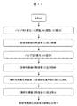
- the flowchart explaining the process of performing biomolecule radiolabeling reaction from introduction
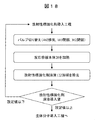
- the figure which shows an example of the flow path used in order to send a sample with respect to a reaction container (Example 16).
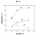
- the graph which shows one example of the result of having implemented the radiochemical reaction in the biomolecule radiolabeling reaction apparatus (Example 17).
- the graph which shows one example of the relationship between the result of having implemented the radiochemical reaction in the biomolecule radiolabeling reaction apparatus, and attenuation of the radioactivity of a labeling agent (Example 17).
- the graph which shows one example of the result of having implemented the radiochemical reaction in the biomolecule radiolabeling reaction apparatus (Example 18).
- the constituent elements are not necessarily indispensable unless otherwise specified or apparently indispensable in principle.
- the shapes when referring to the shapes, positional relationships, etc. of the components, etc., the shapes are substantially the same unless otherwise specified, or otherwise apparent in principle. And the like are included. The same applies to the above numbers and the like (including the number, numerical value, quantity, range, etc.).
- FIG. 1 is an example of a biomolecule radiolabeling reaction apparatus using a biomolecule radiolabeling reaction vessel, and a radiobiomolecule drug is produced by the reaction apparatus. But the use of this invention is not restricted to manufacture of a radioactive biomolecule pharmaceutical.
- the biomolecule radiolabeling reaction apparatus 1 shown in FIG. 1 includes a liquid feeding unit 101, a reaction container unit 201, a recovery unit 301, an exhaust unit 401, a temperature adjustment unit 501, a radiation detection unit 601, and a control unit 701. .
- the liquid feeding unit 101 is a unit used for feeding the biomolecule solution 121, the radiolabeling agent solution 122, and the mixture solution 304.
- the reaction container unit 201 is a unit on which the biomolecule radiolabeling reaction container 10 is mounted, and is used for reacting the biomolecule solution 121 and the radiolabeling agent solution 122 to generate a radiobiomolecule drug.
- the biomolecule radiolabeling reaction vessel 10 here corresponds to the reaction vessel in the present invention.
- the recovery unit 301 is a unit used for recovering the solution (mixture solution) 304 mixed in the biomolecule radiolabeling reaction vessel 10.
- the exhaust unit 401 is a unit that vaporizes and exhausts the solvent of the radiolabeling agent solution 122 introduced into the biomolecule radiolabeling reaction vessel 10.
- the temperature control unit 501 is a unit that manages the temperature of the biomolecule radiolabeling reaction vessel 10.
- the radiation detection unit 601 is a unit that measures the radiation dose of the reaction container unit 201.
- the control unit 701 is a unit that controls the liquid feeding unit 101, the reaction container unit 201, the recovery unit 301, the exhaust unit 401, the temperature adjustment unit 501, and the radiation detection unit 601.
- the control unit 701 is configured by a computer, for example.
- the liquid feeding unit 101 includes (1) liquid feeding switching valves 102 and 103 for switching a solution suction / liquid feeding / waste liquid / closure operation therein, (2) a solution suction line 104, and (3) a solution waste liquid line 105. (4) Syringe 106, (5) Syringe pump 107, (6) Biomolecule solution introduction part 108, (7) Radiolabeling agent solution introduction part 109.
- the liquid feeding unit 101 includes a device (not shown) such as (1) a pressure sensor for monitoring the pressure in the system, (2) a holder for fixing the syringe, (3) a power switch, (4) abnormal Emergency stop switch when operation occurs, (5) Communication connector, (6) Sample loop for introducing a small amount of material, (7) Fitting for connecting each line or sample loop to the switching valve 102, 103, etc. Contains.
- a device such as (1) a pressure sensor for monitoring the pressure in the system, (2) a holder for fixing the syringe, (3) a power switch, (4) abnormal Emergency stop switch when operation occurs, (5) Communication connector, (6) Sample loop for introducing a small amount of material, (7) Fitting for connecting each line or sample loop to the switching valve 102, 103, etc. Contains.
- the reaction container unit 201 includes (1) a biomolecule radiolabeling reaction container 10, (2) a radiation sensor 202, and (3) a retention part 203.
- a biomolecule radiolabeling reaction container 10 and the biomolecule solution introducing unit 108 between the biomolecule radiolabeling reaction container 10 and the radiolabeling agent solution introducing unit 109, between the biomolecule radiolabeling reaction container 10 and the residence.
- the parts 203 are connected by fitting (not shown).
- the recovery unit 301 includes (1) a recovery switching valve 302 for switching between liquid feeding and closing operations, and (2) a mixture solution recovery line 303.
- the recovery switching valve 302 and the staying portion 203 and the recovery switching valve 302 and the mixture solution recovery line 303 are connected by a fitting (not shown).
- the exhaust unit 401 includes (1) an exhaust switching valve 402 for switching exhaust / air supply / closing operation, and (2) an exhaust line 403.
- the exhaust gas switching valve 402 and the exhaust line 403 are connected by a fitting (not shown).
- the temperature control unit 501 sends and receives a temperature control signal 131A and a feedback signal 131B to and from the reaction vessel unit 201. By sending and receiving these signals, the temperature of the biomolecule radiolabeling reaction vessel 10 can be controlled.
- Examples of the method for adjusting the temperature of the biomolecule radiolabeling reaction vessel 10 include a method of circulating a heat medium using a circulating thermostat, a method of using a Peltier element, a ribbon heater, and a plate heater.
- Examples of the temperature control target include a heat medium that circulates around the biomolecule radiolabeling reaction vessel 10 and the outside and inside of the biomolecule radiolabeling reaction vessel 10. For example, by controlling the temperature of a solution flowing inside the biomolecule radiolabeling reaction vessel 10, a solution introduced inside, or a solution close to the solution flowing inside, temperature control can be performed more precisely. Become.
- the radiation detection unit 601 receives the radiation detection signal 132A from the reaction container unit 201, and transmits feedback signals 132B and 132C to the liquid feeding unit 101 and the recovery unit 301.
- the radiation detection unit 601 determines the progress of the radiolabeling reaction based on the detection value of the radiation dose given as the radiation detection signal 132A from the radiation sensor 202, and based on the determination result, the suction / feeding of the liquid feed switching valve 102
- a feedback signal 132B for switching the liquid and a feedback signal 132C for switching between closing and recovery of the recovery switching valve 302 are output. By this switching, it is possible to recover the target object that grasps the progress of the reaction.
- the radiation sensor 202 in the reaction container unit 201 is formed as close to the flow path in the biomolecule radioactive labeling reaction container 10 as possible to detect the target radiation. In addition, undesired radiation is shielded as long as the intended radiation can be detected. This structure enables more precise radiation detection.
- the control unit 701 monitors and controls the operations of the six units described above. For example, the control unit 701 transmits / receives a control signal 141A and a feedback signal 141B to / from the liquid feeding unit 101, and performs monitoring and control of operations in the liquid feeding unit 101. In addition, the liquid feeding unit 101 relays communication between the control unit 701 and the other five units. Therefore, a data communication signal 142 is transmitted / received between the liquid feeding unit 101 and the reaction vessel unit 201, and a data communication signal 143 is transmitted / received between the liquid feeding unit 101 and the recovery unit 301.
- a data communication signal 144 is transmitted / received between the liquid supply unit 101 and the exhaust unit 401, and a data communication signal 145 is transmitted / received between the liquid supply unit 101 and the temperature adjustment unit 501. In between, a data communication signal 146 is transmitted and received.
- the control unit 701 monitors and controls the reaction vessel unit 201, the recovery unit 301, the exhaust unit 401, the temperature adjustment unit 501, and the radiation detection unit 601 through these data communication signals.
- control unit 701 controls the switching of the switching valves 102 and 103 in the liquid feeding unit 101, controls the suction of the solution into the syringe 106 and the liquid feeding by the drive control of the syringe pump 107, Control of discarding the filled solution into a waste liquid tank (not shown) or the like is executed.
- the control unit 701 also controls the suspension and resumption of liquid feeding control and suction control.
- a “time delay” of the liquid feeding can be set, and the liquid feeding time can be changed for each syringe 106.
- an input file that indicates two or more continuous operations related to the operation of the syringe 106 and the valve during the suction / liquid feeding process is created in advance and read into the control unit 701, a series of operations are performed. It is also possible to execute automatic control of the operation. Equipped with an automatic control function makes it possible to avoid radiation exposure and perform remote automatic operation. Further, if the above-mentioned input file is stored in a storage area in the control unit 701 and is read and operated as necessary, the input file can be appropriately rewritten.
- control unit 701 is a system pressure data obtained from a pressure sensor (not shown) installed in the liquid feeding unit 101, temperature information obtained from the temperature adjustment unit 501, and radiation detection value obtained from the radiation detection unit 601. And time data can be recorded in the internal storage area.
- control unit 701 determines in advance a threshold value for the pressure in the system based on pressure resistance information such as a pressure sensor and a switching valve, the control unit 701 makes the entire apparatus emergency when the pressure in the system exceeds the threshold value. It can also be stopped.
- the material of the material may be any material as long as it does not adversely affect the reaction to be performed and does not adsorb substances in the solution to be delivered, and it should be changed as appropriate according to the temperature, concentration, and physical properties of the solution flowing inside. Is also possible. Examples of such materials include tungsten, stainless steel, silicon, glass, hastelloy, silicon resin, and fluorine-based resin. In addition, such materials include glass lining, stainless steel, silicon coated surfaces such as nickel and gold, silicon surface oxidized, so-called corrosion resistance improved, and adsorptivity reduced. What was made can also be used.
- FIG. 2 the expansion
- the biomolecule radiolabeling reaction vessel 10 includes a reaction vessel main body 20 formed from a PEEK plate material having a thickness of several millimeters, and a lid member formed from a PEEK plate material arranged on the upper surface side of the reaction vessel main body 20. 30, a lid member 40 formed from a SUS316 stainless steel plate material disposed on the upper surface side of the lid member 30, an adapter member 50 formed from a PEEK plate material disposed on the lower surface side of the reaction vessel body 20, and a lower surface of the adapter member 50 It has the adapter member 60 formed from the SUS316 stainless steel plate material arrange
- the biomolecule radiolabeling reaction vessel 10 is constructed by laminating these adapter member 60, adapter member 50, reaction vessel main body 20, lid member 30, and lid member 40, and fastening their peripheral portions with screws (not shown). Is done.
- the lid member 30 constitutes the ceiling portion of the flow path opened upward formed on the surface side (upper surface in the drawing) of the reaction vessel main body 20.
- Outlet ports 31 for vaporizing and exhausting the solvent from the reaction vessel body 20 are formed on the surface of the lid member 30 facing the reaction vessel body 20 (lower surface in the drawing). It communicates with the upper side.
- An outlet 41 for vaporizing the solvent from the reaction vessel body 20 and exhausting it is formed on the surface of the lid member 40 facing the lid member 30 (lower surface in the figure).
- the outlet 41 communicates with a gas outlet 42 formed on the surface of the lid member 40 (upper surface in the drawing).
- An inlet port portion 51 for introducing a biomolecule solution or a radioactive labeling agent solution into the reaction vessel main body 20 and the mixture solution are discharged to a surface (upper surface in the drawing) of the adapter member 50 facing the reaction vessel main body 20.
- An outlet port portion 52 is formed and communicates with the lower surface of the adapter member 50.
- An inlet portion 61 for introducing a biomolecule solution or a radioactive labeling agent solution into the reaction vessel main body 20 and an outlet portion for discharging the mixture solution are provided on the surface of the adapter member 60 facing the adapter member 50 (upper surface in the drawing). 62 is formed.
- the inlet 61 communicates with a biomolecule solution inlet 63 and a radiolabeling agent solution inlet 64 formed on the back surface (lower surface in the drawing) of the adapter member 60.
- the outlet 62 communicates with the mixture solution outlet 65 formed on the back surface (lower surface in the drawing) of the adapter member 60.
- the outlet port portion 31 is formed in the lid member 30, and the outlet portion 41 is formed in the lid member 40. You may use the exit port part 52 formed in the member 50, the exit part 62 formed in the adapter member 60, and the mixture solution discharge port 65.
- FIG. 1 In this embodiment, in order to vaporize and exhaust the solvent from the reaction vessel main body 20, the outlet port portion 31 is formed in the lid member 30, and the outlet portion 41 is formed in the lid member 40. You may use the exit port part 52 formed in the member 50, the exit part 62 formed in the adapter member 60, and the mixture solution discharge port 65.
- the lid member 30 and the lid member 40, and the adapter member 50 and the adapter member 60 are provided with two different materials, respectively, which stabilizes the flow path formed in the reaction vessel main body 20. This is because the difference in hardness between the SUS316 stainless steel plate material and the PEEK plate material forming the reaction vessel body 20 is taken into consideration.
- a lid member 30 made of the same PEEK material as the reaction vessel body 20 is installed between the SUS316 stainless steel plate lid member 40 and the reaction vessel body 20, and the reaction vessel body is placed between the adapter member 60 and the reaction vessel body 20.
- An adapter member 50 made of the same PEEK material as that 20 is installed.
- the lid members 30 and 40 and the adapter members 50 and 60 are configured by one member formed of the SUS316 stainless steel plate material. May be.
- the lid member 40 and the adapter member 60 are formed of SUS316 stainless steel plate material, but may be formed of a material capable of shielding the radiation of the radioactive labeling agent introduced into the reaction vessel main body 20. Examples of such a material include tungsten, lead, a shielding workpiece, and the like. When such a material that shields radiation is used, it is necessary to form a space for radiation detection in either one or both of the lid member 40 and the adapter member 60.
- the reaction vessel main body 20 is formed of a PEEK plate material.
- the reaction vessel main body 20 does not adversely affect the reaction performed in the reaction vessel main body 20, and the substance in the solution introduced into the reaction vessel main body 20 does not adsorb. It may be sufficient, and can be appropriately changed according to the type of reaction. Examples of such materials include stainless steel, silicon, gold, glass, hastelloy, silicon resin, and fluorine resin. Also, a glass lining, a metal surface coated with nickel or gold, a silicon surface oxidized, so-called improved corrosion resistance, or reduced adsorbability may be used. .
- the material of the above-described seal member may be any material that does not adversely affect the reaction, and can be appropriately changed according to the type of reaction to be performed.
- silicon resin, fluorine resin, or the like can be used.
- the sealable member is an assembly unit that can be disassembled using fluororubber.
- a decomposable reaction vessel is highly maintainable because it can be disassembled and cleaned when clogging or the like occurs inside.
- ten holes or screw holes are formed in the outer peripheral portion of the adapter member 60, the adapter member 50, the reaction vessel main body 20, the lid member 30, and the lid member 40 to facilitate screw fastening.
- it is good also as a reaction container which cannot be decomposed
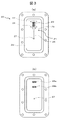
- FIG. 3 shows a front view and a back view of the reaction vessel main body 20 constituting the biomolecule radiolabeling reaction vessel 10.
- FIG. 4 the elements on larger scale of the liquid feeding structure formed in the reaction container main body 20 are shown.
- FIG. 3 As shown in FIG. 3, four holes for fastening in the longitudinal direction and three for fastening in the lateral direction are formed in the peripheral portion of the reaction vessel main body 20.
- a rectangular groove 29 having a rounded corner is provided on the center side of the hole.
- a seal member (not shown) is attached to the groove 29.
- FIG. 4 shows a partially enlarged view of the flow path.
- the flow channel 21 includes, in order from the upstream side, a biomolecule solution supply unit 22, a biomolecule solution guide channel unit 23, a radiolabeling agent solution supply unit 24, and a funnel-shaped radiolabeling agent.
- the solidification unit 25, the discharge side flow path unit 26, and the mixed solution discharge unit 27 are configured.
- Each of the biomolecule solution guide channel sections 23 is configured as an aggregate of 31 channels (first channels) each having a certain width and formed apart by a certain width in the width direction. .
- Each flow path constituting the biomolecule solution guiding flow path section 23 is configured as a space sandwiched between two walls formed in parallel with each other. Both ends of the 31 channels are formed as open ends.
- a biomolecule solution supply unit 22 that introduces the biomolecule solution 121 from the back side of the reaction vessel main body 20 is formed in the most upstream part of the 31 channels.
- the biomolecule solution 121 introduced from the biomolecule solution supply unit 22 is guided as a belt-like flow to the outlet located on the lower end side in the drawing.
- the outlet of the biomolecule solution guide channel 23 is connected to the inlet opening of the radioactive labeling agent solidifying unit 25.
- the biomolecule solution supply unit 22 is formed by 31 openings (biomolecule solution supply nozzle 22A) that connect the front surface and the back surface of the reaction vessel main body 20.
- the biomolecule solution supply nozzles 22 ⁇ / b> A are formed in one row in the width direction of the reaction container body 20 at substantially the same length interval as the surface diameter of the nozzles.
- the biomolecule solution 121 is introduced into the biomolecule solution guide channel portion 23 through the biomolecule solution supply nozzle 22A.
- a biomolecule solution reservoir 28a for temporarily storing a biomolecule solution 121 as a supply liquid is formed on the back surface of the reaction vessel body 20, and the biomolecule solution An opening on the back side of the biomolecule solution supply nozzle 22A is located in the region of the reservoir 28a.
- the biomolecule solution reservoir 28a is formed as a recess recessed in the thickness direction with respect to the back surface of the reaction vessel main body 20.
- the biomolecule solution reservoir 28 a is connected to the inlet port portion 51 of the adapter member 50.
- the radiolabeling agent solution supply unit 24 is disposed in a space sandwiched by 31 channels constituting the biomolecule solution guiding channel unit 23, and the radiolabeling agent solidifying unit 25 of the radiolabeling agent solution 122 is disposed. Used for introduction to. As shown in FIG. 4, when the biomolecule solution guiding channel portion 23 is formed as 31 parallel channels, each channel has the same width as the biomolecule solution guiding channel portion 23. And 30 flow paths (second flow paths) that are separated by a certain width in the width direction are formed. In the present embodiment, the radioactive labeling agent solution supply unit 24 is disposed at the most downstream position of these 30 flow paths.
- the outflow port of the second flow path where the radiolabeling agent solution supply unit 24 is arranged is connected to the inlet side opening of the radiolabeling agent solidifying unit 25.
- the radiolabeling agent solution supply unit 24 is formed by 30 openings (radiolabeling agent solution supply nozzle 24A) that connect the front surface and the back surface of the reaction vessel main body 20.
- the radioactive labeling agent solution supply nozzles 24 ⁇ / b> A are formed in one row in the width direction of the reaction container main body 20 at substantially the same length interval as the surface diameter of the nozzles.
- the radiolabeling agent solution 122 is introduced into the radiolabeling agent solidifying section 25 through the radiolabeling agent solution supply nozzle 24A.
- a radiolabeling agent solution reservoir 28b for temporarily storing a radiolabeling agent solution 122 as a supply liquid is formed on the back surface of the reaction vessel main body 20.
- the opening on the back side of the radiolabeling agent solution supply nozzle 24A is located in the region of the radiolabeling agent solution reservoir 28b.
- the radioactive labeling agent solution reservoir 28b is formed as a recess recessed in the thickness direction with respect to the back surface of the reaction vessel main body 20.
- the radioactive labeling agent solution reservoir 28 b is connected to the inlet port 51 of the adapter member 50.
- the radioactive labeling agent solidifying portion 25 is formed as a concave portion recessed in the thickness direction with respect to the surface of the reaction vessel main body 20.
- the bottom surface is formed lower than the biomolecule solution guide channel 23. This makes it possible to store the introduced radiolabeling agent solution 122 during the process of removing the solvent and solidifying the solution.
- the exhaust outlet port part 31 when the solvent of the radioactive labeling agent solution 122 is vaporized and removed on the surface of the lid member 30 facing the reaction container main body 20 is radioactively labeled.
- the radioactive labeling agent solution is formed at a position away from the inflow side and the outflow side of the agent solidifying part 25 so as not to flow out.
- the outlet port portion 31 is connected to the outlet portion 41 of the lid member 40. Thereby, the solvent of the radioactive labeling agent solution 122 introduced into the radioactive labeling agent solidifying part 25 of the reaction vessel main body 20 is exhausted from the exhaust port 42 formed on the surface (upper surface in the drawing) side of the lid member 40. .
- the bottom surface of the radioactive labeling agent solidifying portion 25 described above has a depth such that the radioactive labeling agent solution 122 does not flow out from the exhaust outlet port portion 31 of the lid member 30.
- a filter that does not allow liquid to pass therethrough and allows only gas to pass therethrough may be provided on the side of the reaction vessel body 20 of the exhaust outlet port portion 31. With this filter, it is possible to prevent the solution from flowing out even when the radioactive labeling agent solution 122 reaches the exhaust outlet port portion 31.
- the radiolabeling agent solidifying section 25 is manufactured in a funnel shape so that the flow path width on the inflow side is the widest and the flow path width is narrower on the outflow side.
- the outlet of the radioactive labeling agent solidifying part 25 is connected to a discharge channel part 26 having a predetermined length having the same channel width as the mouth width.
- the multilayer flow formed by 31 strip-like flows introduced into the radiolabeling agent solidifying portion 25 is introduced into the discharge-side flow passage portion 26 in a contracted state in the width direction. be able to. That is, even if the flow passage width of the discharge-side flow passage portion 26 is somewhat large, the width of the laminar flow formed therein can be reduced. In this way, by introducing the biomolecule solution 121 that has passed over the solidified radiolabeling agent into the discharge-side flow path portion 26 as a large number of laminar flows, stable mixing can be achieved while securing the liquid feeding amount. Become.
- the mixture solution in which the reaction has progressed in the channel 21 is guided to the mixture solution discharge unit 27.
- the mixed solution discharge portion 27 is formed as a hole connecting from the front surface to the back surface of the reaction vessel main body 20. Therefore, the mixture solution is led out from the front surface of the reaction vessel body 20 to the back surface.
- the mixed solution discharge part 27 on the back surface side of the reaction container main body 20 is connected to the outlet port part 52 of the adapter member 50. Further, the outlet port part 52 is connected to the outlet part 62 of the adapter member 60. Thereby, the mixture solution generated in the flow path of the reaction vessel main body 20 is discharged from the mixture solution discharge port 65 formed on the back surface (lower surface in the drawing) side of the adapter member 60.
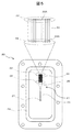
- FIG. 5 shows a front view of a reaction vessel main body 20 constituting the biomolecule radiolabeling reaction vessel 10 and a partially enlarged view of a liquid feeding structure formed in the reaction vessel main body 20.
- reaction vessel main body 20 in this example is the same as that in Example 1 unless otherwise specified.
- the biomolecule solution supply nozzle 22A in the biomolecule solution supply unit 22 and the radiolabeling agent solution supply nozzle 24A in the radiolabeling agent solution supply unit 24 are formed in the same flow path.
- the number of channels of the biomolecule solution guiding channel section 23 is 61, and the biomolecule solution 121 is supplied to the radioactive labeling agent solidifying section 25 as a laminar flow approximately twice as large as that of the first embodiment. Thereby, the interaction between the biomolecule solution 121 and the solidified radioactive labeling agent is increased, and the rapid progress of the reaction is realized.
- the surface diameter of the radioactive labeling agent solution supply nozzle 24A is formed to a size that does not hinder the feeding of the biomolecule solution 121 flowing from the upstream side of the flow path where each nozzle is formed.
- FIG. 6 shows a front view and a rear view of the reaction container body 20 constituting the biomolecule radiolabeling reaction container 10, and a partially enlarged view of the liquid feeding structure formed in the reaction container body 20.
- reaction vessel main body 20 in this example is the same as that in Example 1 unless otherwise specified.
- the flow path 21 in the present embodiment is configured as a continuous space having a certain width, sandwiched between two parallel walls, and having a radioactive labeling agent solidifying portion 25 formed in the middle portion. Both ends of the channel are formed as open ends.
- a biomolecule solution supply unit 22 for introducing the biomolecule solution 121 from the back surface side of the reaction vessel main body 20 is formed in the most upstream portion of the flow path 21.
- the biomolecule solution 121 introduced from the biomolecule solution supply unit 22 is guided to the mixed solution discharge unit 27 located on the lower end side in the figure via the radiolabeling agent solidifying unit 25.
- the biomolecule solution supply unit 22 is formed by an opening (biomolecule solution supply nozzle 22A) that connects the front surface and the back surface of the reaction vessel main body 20.
- the biomolecule solution 121 is introduced into the biomolecule solution guide channel portion 23 through the biomolecule solution supply nozzle 22A.
- the opening on the back surface of the reaction vessel main body 20 of the biomolecule solution supply nozzle 22 ⁇ / b> A is connected to the inlet port portion 51 of the adapter member 50.
- the radiolabeling agent solution supply unit 24 is disposed upstream of the radiolabeling agent solidifying unit 25 and is used for introducing the radiolabeling agent solution 122 into the radiolabeling agent solidifying unit 25.
- the radioactive labeling agent solution supply unit 24 is formed by an opening (radiolabeling agent solution supply nozzle 24 ⁇ / b> A) that connects the front surface and the back surface of the reaction container body 20. As shown in FIG. 6, the surface diameter of the radioactive labeling agent solution supply nozzle 24 ⁇ / b> A is determined based on the flow rate of the flow channel 21 that continues from the biomolecule solution guiding channel portion 23, the radiolabeling agent solidifying portion 25, and the discharge side channel portion 26. It is formed smaller than the road width.
- the size is formed so as not to hinder the feeding of the biomolecule solution 121 introduced from the biomolecule solution guide channel 23.
- the radiolabeling agent solution 122 is introduced into the radiolabeling agent solidifying section 25 through the radiolabeling agent solution supply nozzle 24A.
- the radioactive labeling agent solution supply nozzle 24 ⁇ / b> A is connected to the back surface of the reaction vessel main body 20, and the back surface side opening is connected to the inlet port portion 51 of the adapter member 50.
- the radioactive labeling agent solidifying part 25 is a channel formed in the middle part of the channel 21.
- the bottom surface may be formed lower than the biomolecule solution guide channel portion 23 and the discharge side channel portion 26.
- the radiolabeling agent solidifying part 25 is formed in a straight line, but depending on the volume of the radiolabeling agent solution 122 introduced into the radiolabeling agent solidifying part 25, meandering, It may be formed in a spiral shape. By these, the capacity
- a radioactive labeling agent solidified by the radioactive labeling agent solidifying unit 25 may be of a size that does not inhibit the feeding of the biomolecule solution 121.
- FIG. 7 shows a front view and a rear view of the reaction container body 20 constituting the biomolecule radiolabeling reaction container 10, and a partially enlarged view of the liquid feeding structure formed in the reaction container body 20.
- reaction vessel main body 20 in this example is the same as that in Example 1 unless otherwise specified.
- the radioactive labeling agent solution supply section 24 is formed in the middle of the biomolecule solution guiding channel section 23 in the second embodiment.
- the biomolecule solution guide channel 23 after the radiolabeling agent solution supply unit 24 is used as the radiolabeling agent solidifying unit 25 ′ in the present embodiment, the funnel-shaped radiolabeling agent solidifying unit 25 and the discharge side flow in the second embodiment.
- the passage portion 26 is also referred to as a discharge-side passage portion 26 ′ in the present embodiment.
- the bottom surface of the radiolabeling agent solidifying portion 25 ′ may be formed lower than the biomolecule solution guiding channel portion 23 and the discharge side channel portion 26 ′. As a result, the capacity of the introduced radiolabeling agent solution 122 can be increased during the process of removing the solvent and solidifying the solution.
- the channel width and depth that are formed on the surface of the reaction vessel main body 20 in the present embodiment and extend from the biomolecule solution guiding channel unit 23 to the radiolabeling agent solidifying unit 25 ′ are the same as the radiolabeling agent solidifying unit 25 ′.
- the radioactive labeling agent solidified in step 1 can be used as long as it does not hinder the feeding of the biomolecule solution 121.
- the radioactive labeling agent solidifying portion 25 ′ where the solidified radioactive labeling agent interacts with the biomolecule solution 121 becomes a plurality of parallel flow paths, it is constant while maintaining the performance of the third embodiment. Increase in throughput over time can be realized.
- the radiation sensor 202 is used in the biomolecule radiolabeling reaction apparatus 1 to detect radiation related to the biomolecule radiolabeling reaction process.
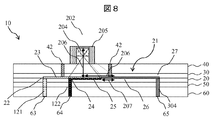
- FIG. 8 shows a cross-sectional view of the biomolecule radiolabeling reaction vessel 10 shown in FIG.
- the radiation sensor 202 includes a radiation detector 204 and a radiation shielding unit 205.
- the radiation sensor 202 is formed on the lid member 40 in the flow path formed on the surface of the reaction vessel main body 20, vertically above the radioactive labeling agent solidifying portion 25.
- the size of the entrance of the detector 204 and the shielding unit 205 on the side of the lid member 40 and the distance from the lid member 40 of the detector 204 are set in parts other than the radioactive labeling agent solidifying unit 25 in the biomolecule radiolabeling reaction apparatus 1. It is only necessary that the radiation of the radioactive labeling agent solidifying unit 25 can be detected without being affected by the radiation emitted from the radioactive substance located.
- the detection sensitivity increases as the distance 206 from the detector 204 to the radioactive labeling agent solidifying unit 25 is shorter. Further, the radiation of the radioactive substance located outside the radioactive labeling agent solidifying unit 25 is detected by a distance corresponding to the distance 206 from the detector 204 to the radioactive labeling agent solidifying unit 25.
- the shielding part 205 is formed on the outer periphery of the detector 204 in order to prevent the influence of the radiation emitted from the radioactive substance located outside the radiopharmaceutical solidifying part 25.
- the material of the shielding part 205 should just shield the radiation emitted from the radioactive substance to be used. Such materials include tungsten, lead, shielding workpieces, and the like.
- the thickness of the shielding object should just be more than the thickness corresponding to the radiation dose to shield.
- the upper part of the detector 204 where no radioactive substance is located is formed with a thickness capable of shielding radiation generated from the environment in which the biomolecule radioactive labeling reaction apparatus 1 is used.
- the left and right side portions of the detector 204 where the radioactive substance is located have a length 207 obtained by subtracting the distance in the radioactive labeling agent solidifying unit 25 from the distance 206 from the detector 204 to the radioactive labeling agent solidifying unit 25 shown in FIG. It is formed with a thickness capable of shielding the radiation emitted from the radioactive material located.
- the entrance width of the detector is narrowed by the shielding unit 205, it is possible to prevent detection of radiation other than the radioactive labeling agent solidifying unit 25. Any width may be used as long as the radiation of the radioactive labeling agent solidifying unit 25 can be detected.
- the present embodiment can be formed on the lid member 40 above the radioactive labeling agent solidifying part 25 according to the flow path on the reaction container body 20 and the configuration of the biomolecule radiolabeling reaction container 10. Excellent versatility.
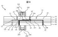
- FIG. 9 shows a cross-sectional view of the biomolecule radioactive labeling reaction vessel 10 shown in FIG. 2 laminated and cut along a plane passing through the reaction vessel body 20. Points not particularly specified are the same as those in the fifth embodiment.
- the radiation sensor 202 formed on the lid member 40 in the sixth embodiment is formed opposite to the adapter member 60.
- a high detection sensitivity can be realized by using two radiation detectors 204 facing each other.
- the shielding unit 205 is not necessary by performing simultaneous counting.
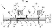
- FIG. 10 shows a cross-sectional view of the biomolecule radioactive labeling reaction vessel 10 shown in FIG. Points not particularly specified are the same as those in the fifth embodiment.
- another radiation sensor 202 formed in the upper part of the radioactive labeling agent solidifying part 25 of the lid member 40 in Example 6 is formed on the upper part of the mixture solution discharge part 27 of the lid member 40.
- the progress of the reaction can be monitored by two methods. That is, using the radiation sensor 202 formed on the radiolabeling agent solidifying unit 25, a monitor for the amount of radiolabeling agent that dissolves and decreases in the biomolecule solution 121 is installed on the mixture solution discharge unit 27. Using the radiation sensor 202, the amount of radioactive material increasing in the mixed solution 304 can be monitored.
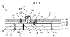
- FIG. 11 shows a cross-sectional view of the biomolecule radioactive labeling reaction vessel 10 shown in FIG. Points not particularly specified are the same as those in the fifth embodiment.
- the lid member 40 is made of tungsten shielding material. As such a material, it is only necessary to shield radiation emitted from a radioactive substance to be used. In addition to tungsten, lead, concrete, processed workpieces for shielding, and the like can be given.
- the thickness of the lid member 40 is equal to or greater than the thickness corresponding to the radiation dose to be shielded, and is equal to or greater than the thickness at which the flow path formed on the reaction vessel main body 20 is maintained by stacking the radiolabeled reaction vessels 10 I do not care.
- a space 208 for detecting radiation emitted from the radioactive labeling agent solidifying unit 25 is formed in the lid member 40.
- the space 208 penetrates the lid member 40 and can detect the radiation of the radioactive labeling agent solidifying unit 25. From the distance 206 from 204 to the radioactive labeling agent solidifying unit 25 shown in FIG. It is formed with a width that can shield the radiation of a radioactive substance having a length of 207 minutes minus the distance.
- the shielding part 205 formed on the upper part and both lateral parts of the detector 204 is formed with a thickness capable of shielding the radiation generated from the environment in which the biomolecule radioactive labeling reaction apparatus 1 is used.
- the position of the radioactive labeling agent solidifying part 25 is the same in the flow path on the reaction container main body 20, it can be applied to the reaction container main body 20 of a different flow path type. A simple structure can be realized.
- FIG. 12 shows a cross-sectional view of the biomolecule radioactive labeling reaction vessel 10 shown in FIG. 2 laminated and cut along a plane passing through the reaction vessel main body 20. Points not particularly specified are the same as those in the eighth embodiment.
- the radiation sensor 202 formed on the lid member 40 in the eighth embodiment is formed opposite to the adapter member 60.
- the adapter member 60 is made of tungsten.
- a space portion 208 for detecting radiation emitted from the radiolabeling agent solidifying portion 25 is formed in the adapter member 60.
- a high detection sensitivity can be realized by using two radiation detectors 204 facing each other.
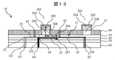
- FIG. 13 shows a cross-sectional view of the biomolecule radioactive labeling reaction vessel 10 shown in FIG. Points not particularly specified are the same as those in the eighth embodiment.
- another radiation sensor 202 formed on the radioactive labeling agent solidifying portion 25 of the lid member 40 in the eighth embodiment is formed on the mixture solution discharge portion 27 of the lid member 40.
- a space 208 for detecting the radiation of the mixture solution discharge unit 27 is also formed in the lid member 40 at the top of the mixture solution discharge unit 27.
- the progress of the reaction can be monitored by two methods. That is, using the radiation sensor 202 formed on the radiolabeling agent solidifying unit 25, a monitor of the amount of the radiolabeling agent that dissolves and decreases in the biomolecule solution 121 is formed on the mixture solution discharge unit 27. Using the radiation sensor 202, the amount of radioactive material increasing in the mixed solution 304 can be monitored.
- the structure of the seventh radiation sensor 202 formed in the biomolecule radioactive labeling container 10 which is a modification of the fifth embodiment will be described.
- FIG. 14 shows a cross-sectional view of the biomolecule radioactive labeling reaction vessel 10 shown in FIG. 2 which is laminated and cut along a plane passing through the reaction vessel main body 20. Points not particularly specified are the same as those in the fifth embodiment.
- the radiation sensor 202 is formed in the lid member 40.
- the shielding part 205 has a thickness that can shield radiation generated from the environment in which the biomolecule radioactive labeling reaction apparatus 1 is used. It can be formed.
- the structure of the eighth radiation sensor 202 formed in the biomolecule radioactive labeling container 10 which is a modification of the eleventh embodiment will be described.
- FIG. 15 shows a cross-sectional view of the biomolecule radioactive labeling reaction vessel 10 shown in FIG. 2 which is laminated and cut along a plane passing through the reaction vessel main body 20.
- the points not particularly specified are the same as in Example 11.
- the radiation sensor 202 formed in the lid member 40 in the eleventh embodiment is formed opposite to the adapter member 60.
- the shielding unit 205 is not necessary by performing simultaneous counting.
- the structure of the ninth radiation sensor 202 formed in the biomolecule radioactive labeling container 10 which is a modification of the eleventh embodiment will be described.
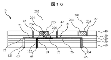
- FIG. 16 shows a cross-sectional view of the biomolecule radioactive labeling reaction vessel 10 shown in FIG. 2 stacked and cut along a plane passing through the reaction vessel main body 20.
- the points not particularly specified are the same as in Example 11.
- another radiation sensor 202 formed in the upper part of the radioactive labeling agent solidifying part 25 in the lid member 40 in Example 11 is formed in the upper part of the mixture solution discharge part 27 in the lid member 40.
- the progress of the reaction can be monitored by two methods. That is, using the radiation sensor 202 installed on the radiolabeling agent solidifying unit 25, a monitor of the amount of the radiolabeling agent that dissolves and decreases in the biomolecule solution 121 is installed on the mixture solution discharge unit 27. Using the radiation sensor 202, the amount of radioactive material increasing in the mixed solution 304 can be monitored.
- FIG. 17 shows the step of introducing the radiolabeling agent solution
- FIG. 18 shows the step of removing the solvent of the radiolabeling agent solution
- FIG. 19 shows the steps from the step of introducing the biomolecule solution to the biomolecule radiolabeling reaction. Indicates.
- Radiolabeling agent solution introduction and solvent removal step First, the steps of introducing the radiolabeling agent solution 122 into the biomolecule radiolabeling reaction vessel 10 and removing the solvent from the radiolabeling agent solution 122 will be described with reference to FIGS. .
- the liquid supply switching valve 102 and the exhaust switching valve 402 are closed, and the recovery switching valve 302 is switched to recovery.
- the setting of the liquid feed switching valve 103 is switched so that the radioactive labeling agent solution 122 sucked from the solution suction line 104 is sent to the syringe 106. Thereafter, the syringe pump 107 is pulled downward in the figure, and the radioactive labeling agent solution 122 is introduced into the syringe 106 through the solution suction line 104 and the liquid feed switching valve 103.
- the liquid feed switching valve 103 is switched so that the radioactive labeling agent solution 122 is fed from the syringe 106 toward the radioactive labeling agent solution introduction unit 109.
- the syringe pump 107 on the radiolabeling agent solution side is pushed upward in the figure, and the radiolabeling agent solution 122 in the syringe 106 is passed through the liquid feed switching valve 103 and the radiolabeling agent solution introduction unit 109.
- the solution is sent to the biomolecule radiolabeling reaction vessel 10.
- the radioactive labeling agent solution 122 fed from the radioactive labeling agent solution introduction unit 109 is introduced into the biomolecule radiolabeling reaction container 10 from the radiolabeling agent solution introduction port 64 formed on the lower surface of the adapter member 60.
- the radioactive labeling agent solution introduction port 64 is formed to have a large diameter for mounting a socket (not shown), and the adapter member 60, a small hole in the adapter member 50, and an inlet port portion 51 installed on the upper side surface of the adapter member 50. Then, the radiolabeling agent solution 122 is guided to the radiolabeling agent solution reservoir 28b.
- the radiolabeling agent solution reservoir 28b has a minimum capacity for storing an amount of the radiolabeling agent solution 122 that can be supplied to all the radiolabeling agent solution supply nozzles 24A at an equal pressure.
- the radioactive labeling agent solution 122 filling the radioactive labeling agent solution reservoir 28b is supplied at a pressure equal to the radioactive labeling agent solution supply nozzle 24A.
- the radioactive labeling agent solution 122 is discharged almost uniformly from all the radioactive labeling agent solution supply nozzles 24A, and is guided from each of the radioactive labeling agent solution supply nozzles 24A to the radioactive labeling agent solidifying unit 25.
- the radiolabeling agent solution supply nozzle 24A is formed in the radiolabeling agent solution supply unit 24 at the terminal end (lowermost part) of the biomolecule solution guiding channel unit 23, as shown in FIG.
- the position of the radioactive labeling agent solution supply nozzle 24 ⁇ / b> A is shifted in the width direction of the reaction vessel main body 20 by one biomolecule solution supply nozzle 22 ⁇ / b> A.
- the surface diameter of the radioactive labeling agent solution supply nozzle 24 ⁇ / b> A is approximately the same as the channel width and channel depth of each channel of the biomolecule solution guiding channel unit 23.
- the exhaust switching valve 402 After confirming the introduction of the radioactive labeling agent solution 122 into the radioactive labeling agent solidifying unit 25 by increasing the radiation dose using the radiation sensor 202, the exhaust switching valve 402 is set in the exhaust direction, the liquid feeding switching valve 103 and the recovery switching. Switch valve 302 to closed.
- the temperature control unit 501 heats the biomolecule radiolabeling reaction vessel 10 to remove the solvent of the radiolabelling agent solution 122.
- the amount of the radiolabeling agent solution 122 introduced into the biomolecule radiolabeling reaction vessel 10 is set to a capacity sufficient to fill the radiolabeling agent solidifying part 25.
- the steps of introducing the radiolabeling agent solution 122 into the radiolabeling agent solidifying portion 25 and removing the solution of the radiolabeling agent solution 122 are radioactive.
- the introduction of the radioactive labeling agent solution 122 into the labeling agent solidifying part 25 is repeated until the necessary amount is reached.
- the radioactive labeling agent solution introduction unit 109 before the biomolecule radiolabeling reaction vessel 10 and the syringe 106 remain.
- the radiolabeling agent solution 122 to be discharged may be discharged and filled with a solvent or air. By performing this step, it is possible to prevent the influence of the radiolabeling agent solution 122 remaining in the radiolabeling agent solution introducing portion 109 and the syringe 106 when monitoring the radioactivity during the reaction. Further, by filling the solvent, it is possible to prevent the backflow to the radioactive labeling agent solution introduction unit 109 when the biomolecule solution 121 is sent back and forth.
- the radiolabeling agent solidifying unit 25 is formed using a separately formed radiation sensor 202 (for example, Examples 7, 10, and 13) (not shown). If the presence or absence of outflow of the radioactive labeling agent solution 122 to other than the above is confirmed, this process is further ensured.
- the radiolabeling agent solution 122 is moved from the biomolecule radiolabeling reaction vessel 10 to the syringe through the liquid feed switching valve 103. It switches so that it may send in the direction of 106. After this switching, the syringe pump 107 on the radiolabeling agent solution side is pushed downward in the figure, and the radiolabeling agent solution 122 in the biomolecule radiolabeling reaction vessel 10 is switched to the radiolabeling agent solution introduction unit 109 and the liquid feeding switching. It collects in the syringe 106 through the valve 103.
- the liquid supply switching valve 103 is fed and the recovery switching valve 302 is kept in the collection state.
- the syringe pump 107 on the agent solution side is pushed upward in the figure, and the radioactive labeling agent solution 122 in the biomolecule radioactive labeling reaction vessel 10 is recovered via the retention part 203 and the mixture solution recovery line 303.
- the heating temperature is set to around the boiling point of the solvent of the radiolabeling agent solution 122.
- the heating time is set to a time sufficient for removing the solvent. If the time required for the solvent to be removed is confirmed in the preliminary study, this step can be set to the minimum required time. Further, when gas was introduced from the biomolecule solution introduction unit 108 and it was confirmed that the radiation detection amount of the radiolabeling agent solidifying unit 24 did not change using the radiation sensor 202, the solvent removal of the radiolabeling agent solution 122 was completed. I can confirm that.
- the step of removing the solvent of the radiolabeling agent solution 122 may be a method such as introducing gas or reducing pressure in addition to heating the biomolecule radiolabeling reaction vessel 10 described above.
- one of the exhaust lines 403 is used as an air supply line and connected to a gas supply source.
- the gas supply source include a gas line, a gas cylinder, and a balloon storing gas.
- the gas may be any gas that does not affect the reaction performed in the biomolecule radiolabeling reaction vessel 10. Examples of such gas include air, nitrogen, argon and the like.
- the exhaust valve 402 on the side connected to the air supply line is switched to the direction of sending gas to the biomolecule radioactive labeling reaction vessel 10 via the air supply line 403, and the air supply line 403 and the exhaust valve 402 are switched from the gas supply source.
- a gas is introduced into the biomolecule radiolabeling reaction vessel 10 via the via.
- the introduction amount is set to such an amount that the solvent of the radiolabeling agent solution 122 is not discharged from the outlet port portion 31.
- the exhaust line 403 is connected to a vacuum device.
- a vacuum apparatus examples include a vacuum pump and an aspirator. The strength of the reduced pressure is set so that the solvent of the radiolabeling agent solution 122 is not discharged from the outlet port portion 31.
- the recovery switching valve 302 is recovered and the exhaust switching valve 402 is switched to closed.
- the setting of the liquid feeding switching valve 102 is switched so that the biomolecule solution 121 sucked from the solution suction line 104 is fed to the syringe 106. Thereafter, the syringe pump 107 is pulled downward in the figure, and the biomolecule solution 121 is introduced into the syringe 106 through the solution suction line 104 and the liquid feed switching valve 102.
- the liquid feed switching valve 102 is switched so that the biomolecule solution 121 is fed from the syringe 106 toward the biomolecule solution introduction unit 108.
- the biomolecule solution side syringe pump 107 is pushed upward in the figure, and the biomolecule solution 121 in the syringe 106 is biolabeled via the liquid feed switching valve 102 and the biomolecule solution introduction unit 108. Introduce into the container 10.
- the biomolecule solution 121 sent from the biomolecule solution introduction unit 108 is guided into the biomolecule radiolabeling reaction container 10 from the biomolecule solution introduction port 63 formed on the lower surface of the adapter member 60.
- the biomolecule solution inlet 63 is formed to have a large diameter for attaching a socket (not shown), and passes through an adapter member 60, a small hole in the adapter member 50, and an inlet port portion 51 installed on the upper side surface of the adapter member 50.
- the biomolecule solution 121 is guided to the biomolecule solution reservoir 28a.
- the biomolecule solution reservoir 28a has a minimum capacity for storing an amount of biomolecule solution 121 that can be supplied to all the biomolecule solution supply nozzles 22A at an equal pressure.
- the biomolecule solution 121 filling the biomolecule solution reservoir 28a is supplied to all the biomolecule solution supply nozzles 22A at the same pressure. As a result, the biomolecule solution 121 is discharged almost uniformly from all the biomolecule solution supply nozzles 22 ⁇ / b> A, and is guided from each biomolecule solution supply nozzle 22 ⁇ / b> A to the biomolecule solution guide channel portion 23.
- the biomolecule solution guide channel section 23 has a channel width that is approximately the same as the surface diameter of the biomolecule solution supply nozzle 22A, and the channel depth is also approximately the same size. After passing through a channel length that is about ten times as large as this channel width, the biomolecule solution 121 flows out to the radioactive labeling agent solidifying portion 25 in which the channel width is formed in a funnel shape.
- the longitudinal direction of the reaction container body 20 (the flow direction of the solution) from the position of the biomolecule solution supply nozzle 22A. ) Between the first channels constituting the biomolecule solution guide channel 23 so as to be independent of each other as a plurality of strip-like flows of the biomolecule solution 121, the same width as each channel. A space is formed. This space is called a second flow path in this embodiment.
- the biomolecule solution supply nozzle 22A and the radiolabeling agent solution supply nozzle 24A are arranged alternately shifted in the width direction, so that the biomolecule solution 121 discharged from the many biomolecule solution supply nozzles 22A is In the radiolabeling agent solidifying section 25, a multi-layered flow that flows in a band shape is formed.
- the biomolecule solution 121 is passed over the solidified radiolabeling agent of the radiolabeling agent solidifying portion 25 in a multilayer flow and flows into the discharge side flow passage portion 26.
- the cross-sectional area in the width direction of each subdivided flow contracts and accelerates. It becomes a flow and flows into the discharge side flow path portion 26. That is, when moving from the radioactive labeling agent solidifying section 25 to the discharge-side flow path section 26, the width of the solution flow is gradually contracted in the direction perpendicular to the contact interface of the multilayer flow, and the individual components constituting the multilayer flow The length of the solution layer in the width direction becomes narrow.
- the discharge-side flow path portion 26 is a flow path extending in the longitudinal direction of the reaction vessel main body 20, and the end thereof reaches the mixed solution discharge portion 27.
- the length of the discharge side flow path part 26 may be a flow that can secure the time required for mixing the biomolecule solution 121 and the radiolabeling agent. Therefore, the channel width and length of the discharge side channel part 26 may be determined according to the diffusion time of the biomolecule solution 121 and the radiolabeling agent, and the shape thereof is also linear as shown in FIG. There is no need. For example, it may be meandering or spiral.
- a plurality of holes are formed in the outlet port portion 52 of the adapter member 50 and the outlet portion 62 of the adapter member 60 so that the flow path length can be changed according to the purpose.
- the mixed biomolecule solution 121 and the radioactive labeling agent 122 are supplied from the liquid discharge part 26 formed at the lower center of the reaction container body 20 to the outlet port part 52 of the adapter member 50, the outlet part 62 of the adapter member 60, and the mixture solution.
- the syringe pump 107 is stopped and the liquid supply is stopped.
- the radiation remaining in the radioactive labeling agent solidifying unit 25 is detected.
- the setting of the liquid feeding switching valve 102 is switched so that the biomolecule solution 121 is fed backward from the staying part 203 toward the flow path 21.
- the syringe pump 107 is pulled downward in the figure, and the biomolecule solution 121 that has reached the end of the retention portion 203 passes through the discharge side flow passage portion 26, the radioactive labeling agent solidification portion 25, and the biomolecule solution induction flow passage portion 23.
- the syringe pump 107 is stopped and the liquid supply is stopped.
- the above operation is repeated until the radiation dose emitted from the radioactive labeling agent solidifying unit 25 reaches a preset value or less.
- the amount of radiation remaining in the radioactive labeling agent solidifying unit 25 reaches a preset value, the amount of the mixed solution that reciprocates between the radioactive labeling agent solidifying unit 25 and the staying unit 203, via the recovery switching valve 302, from the mixture solution recovery line It collect
- the reciprocating liquid feeding step radiation is detected for each reciprocating liquid feeding, but the number of times of reciprocating liquid feeding until reaching a preset radiation dose value from the degree of decrease in the radiation dose by the first detection or several detections is determined.
- the mixture solution may be recovered. Further, the mixture solution may be collected after detecting the radiation before collection and confirming whether the radiation dose set in advance is reached.
- the radiation may be detected every fixed time, and the mixture solution may be recovered when the radiation dose set in advance is reached.
- the required amount of the biomolecule solution 121 is sandwiched between gases or a solvent and sent.
- the reciprocating liquid feeding range is adjusted by the liquid feeding amount so that only the biomolecule solution 121 passes on the radiolabeling agent solidifying portion 25.
- a sample loop (not shown) may be used when the biomolecule solution 121 is transported by being sandwiched between gases or solvents.
- each part of the biomolecule radiolabeling reaction vessel 10 when handling a small amount of radiolabeling agent in the order of pg will be described using the table shown in FIG.
- the table shown in FIG. 20 shows the size and capacity of each part of the flow path of this example.
- the liquid feeding structure on the reaction vessel main body 20 is the structure of Example 1 shown in FIGS.
- a low volume solution of several tens of ⁇ L to several hundreds of ⁇ L is introduced into the reaction vessel main body 20.
- the biomolecule solution guide channel 23 has 31 channels each having a width and a depth of 200 ⁇ m at intervals of 200 ⁇ m. This volume is 7 ⁇ L.
- the radioactive labeling agent solidifying part 25 for introducing the radioactive labeling agent solution 122 and solidifying the solvent is formed slightly deeper than the depth of 200 ⁇ m of the biomolecule solution guiding channel part 23, and has a funnel shape.
- the volume was 17 ⁇ L measured.
- the volume of the radiolabeling agent solution 122 to be introduced into the radiolabeling agent solidifying portion 25 is 17 ⁇ L or more, the volume is introduced in several batches or the solution is concentrated to reduce the volume to 17 ⁇ L or less.
- the discharge-side channel portion 26 is a linear channel having a width and a depth of 500 ⁇ m and a length of 13 mm, and has a capacity of 3 ⁇ L.
- the volume of the mixed solution discharge section 27 / retention section 203 and the mixture solution recovery line 303, the biomolecule solution reservoir section 28a, the biomolecule solution supply section 22, and The necessary capacity is secured by the capacity of the biomolecule solution introduction unit 108.
- FIG. 21 shows an outline of the liquid supply flow path according to this example.
- the volume of the syringe 106 for feeding the biomolecule solution 121 and the radioactive labeling agent solution 122 may be selected according to the amount of the solution to be fed. In this embodiment, it is 1 mL.
- the channel width of the solution suction line 104 may be selected according to the volumes of the biomolecule solution 121 and the radiolabeling agent solution 122 to be sent. However, when the flow path width becomes narrow, the suction time to the syringe 106 becomes long. In this embodiment, it is 0.5 mm.
- the channel width of the solution waste liquid line 105 may be selected according to the volumes of the biomolecule solution 121 and the radiolabeling agent solution 122 to be sent. In order to reduce the dead volume, it is desirable that the flow path width is narrow, but in order to increase the waste liquid speed, it is desirable that the flow path width is wide. In this embodiment, it is 1 mm.
- the flow path widths of the biomolecule solution introduction unit 108 and the radiolabeling agent solution introduction unit 109 may be selected according to the volumes of the biomolecule solution 121 and the radiolabeling agent solution 122 to be fed. In order to reduce the dead volume, it is desirable that the flow path width is narrow, but in order to increase the liquid feeding capacity, it is desirable that the flow path width is wide. In this embodiment, it is 0.5 mm.
- the flow path width of the retention part 203 and the product recovery line 303 may be selected according to the volumes of the biomolecule solution 121 and the radiolabeling agent solution 122 to be sent. In order to improve reaction efficiency, it is desirable that it is 1 mm or less. In this embodiment, it is 0.5 mm.
- the flow path lengths of the solution suction line 104, the waste liquid line 105, the biomolecule solution introduction unit 108, the radioactive labeling agent solution introduction unit 109, the retention unit 203, and the product recovery line 303 are long enough to prevent operation. good.
- settings are made as follows.
- the channel length of the solution suction line 104 is 600 mm
- the channel length of the waste liquid line 105 is 600 mm
- the channel length of the biomolecule solution introduction unit 108 is 600 mm
- the channel length of the radioactive labeling agent solution introduction unit 109 is 600 mm
- the residence The channel length of the section 203 is 120 mm
- the channel length of the product recovery line 303 is 120 mm.
- the liquid feed switching valve 103 has a small dead volume. Therefore, in this embodiment, the dead volume of the liquid supply switching valve 103 is set to 3.4 ⁇ L.
- the biomolecule radiolabeling reaction apparatus 1 is equipped with a reaction vessel 10 having the dimensions shown in Example 15 (FIG. 20) and a liquid feed channel having the dimensions shown in Example 16 (FIG. 21). The result of having performed biomolecule radiolabeling reaction is shown.
- a neurotensin 0.3 mg / mL borate buffer solution pH 8.9 is used as the biomolecule solution 121, and a 50 MBq [ 18 F] SFB diethyl ether solution is used as the radiolabeling agent solution 122.
- 50 ⁇ L of a 50 MBq [ 18 F] SFB diethyl ether solution is divided into five times and is added to the reaction vessel 10 of the biomolecule radiolabeling reaction apparatus 1 and the radiolabeling agent solidifying portion 25 at 0.5 mL / min at room temperature.
- the reaction vessel 10 was heated to 50 ° C., and diethyl ether was vaporized and removed.
- 50 ⁇ L of neurotensin 0.3 mg / mL borate buffer solution (pH 8.9) was reciprocated at 0.5 mL / min into the reaction vessel 10 of the biomolecule radiolabeling reaction apparatus 1 at room temperature. About one minute was required for one reciprocating liquid feeding, switching of the liquid feeding valve 102, radiation detection, and reverse feeding.
- FIG. 22 is a graph showing the results 801 obtained by monitoring the reaction in this example with the radiation sensor shown in Example 5 (FIG. 8).
- FIG. 22 also shows a result 802 obtained by analyzing the obtained mixture solution 304 by HPLC using a radiation detector.
- the vertical axis represents the radiation dose ratio with the initial radiation dose of the radiolabeling agent solidifying part 25 as 100%, and the horizontal axis represents the mixing time.
- the target product, [ 18 F] SFB-labeled neurotensin improved in yield as the mixing time increased due to the reciprocating solution, but compared with the mixing time of 5 to 10 minutes, the mixing time was 10 to 20 minutes. Then, the yield improvement was slow. This result coincided with the decreasing tendency of the radiation dose of the radioactive labeling agent solidifying part 25 shown in 801.
- the decay of 18 F half-life is shown at 804 on the graph shown in FIG.
- the vertical axis represents the radiation dose ratio with the initial radiation dose of the radiolabeling agent solidifying part 25 as 100%, and the horizontal axis represents the mixing time.
- a curve obtained when the yield of [ 18 F] SFB-labeled neurotensin shown at 802 in FIG. 22 proceeds on the extension line of 802 is shown at 803.
- the [ 18 F] SFB label can be obtained by decay after about 100 minutes of mixing time. It can be seen that the radiation dose of neurotensin decreases. In this reaction, even if the radiation dose at the radiolabeling agent solidifying section 25 does not reach the set value, it is possible to realize the setting that the mixing is stopped when the mixing time reaches 100 minutes.
- the result of monitoring the same operation as that of Example 17 with the radiation sensor shown in Example 7 is shown in a graph in FIG. That is, radiation was monitored at two locations, the radioactive labeling agent solidifying section 25 and the mixed solution discharging section 27.
- the vertical axis of the graph represents the radiation dose ratio with the initial radiation dose of the radiolabeling agent solidifying part 25 as 100%, and the horizontal axis represents the mixing time.
- the monitoring result of the radiolabeling agent solidifying part 25 is 801
- the result of analyzing the obtained mixture solution 304 by HPLC using a radiation detector is 802
- the radiation monitoring result of the mixed solution discharge part 27 is Is shown at 805.
- the radiolabeling agent has been described as an example of the labeling agent.
- the present invention is not limited to the radiolabeling agent, and may be, for example, a fluorescent labeling agent.
Landscapes
- Chemical & Material Sciences (AREA)
- Chemical Kinetics & Catalysis (AREA)
- Health & Medical Sciences (AREA)
- General Health & Medical Sciences (AREA)
- Organic Chemistry (AREA)
- Dispersion Chemistry (AREA)
- Analytical Chemistry (AREA)
- Hematology (AREA)
- Clinical Laboratory Science (AREA)
- Life Sciences & Earth Sciences (AREA)
- Proteomics, Peptides & Aminoacids (AREA)
- Physics & Mathematics (AREA)
- Medicinal Chemistry (AREA)
- Optics & Photonics (AREA)
- Pharmacology & Pharmacy (AREA)
- Epidemiology (AREA)
- Animal Behavior & Ethology (AREA)
- Public Health (AREA)
- Veterinary Medicine (AREA)
- Automatic Analysis And Handling Materials Therefor (AREA)
- Medical Preparation Storing Or Oral Administration Devices (AREA)
- Medicines Containing Antibodies Or Antigens For Use As Internal Diagnostic Agents (AREA)
- Physical Or Chemical Processes And Apparatus (AREA)
Abstract
Description
[全体構成]
本発明に係る反応容器を生体分子放射性標識化反応に応用する場合について説明する。図1は、生体分子放射性標識化反応容器を用いた生体分子放射性標識化反応装置の実施例であり、当該反応装置により放射性生体分子薬剤が製造される。もっとも、本発明の用途は、放射性生体分子薬剤の製造に限らない。
送液ユニット101は、(1)その内部に溶液の吸引・送液・廃液・閉鎖操作を切り替えるための送液切り替えバルブ102、103、(2)溶液吸引ライン104、(3)溶液廃液ライン105、(4)シリンジ106、(5)シリンジポンプ107、(6)生体分子溶液導入部108、(7)放射性標識化剤溶液導入部109を有している。この他、送液ユニット101には、不図示のデバイス、例えば(1)系内の圧力を監視する圧力センサ、(2)シリンジを固定するためのホルダ、(3)電源スイッチ、(4)異常動作を起こした場合の非常停止スイッチ、(5)通信用コネクタ、(6)小量の原料を導入するサンプルループ、(7)各ラインやサンプルループを切り替えバルブ102、103に接続するフィッティング等を含んでいる。
本実施例では遮蔽部205の放射性標識化剤固化部25側の開口幅を適切に設定すれば、遮蔽部205は生体分子放射性標識化反応装置1を使用する環境から発生する放射線を遮蔽できる厚さで形成可能である。
まず、図1~図4、図17、図18を用い、放射性標識化剤溶液122の生体分子放射性標識化反応容器10への導入と、放射性標識化剤溶液122の溶媒の除去工程を説明する。
次に、図1~図4、図19を用い、生体分子溶液121の生体分子放射性標識化反応容器10への導入と、生体分子と放射性標識化剤の反応の工程を説明する。
なお、本実施例においては、ニューロテンシン0.3mg/mLホウ酸緩衝液(pH8.9)を生体分子溶液121、50MBqの[18F]SFBジエチルエーテル溶液を放射性標識化剤溶液122とする。
続いて、ニューロテンシン0.3mg/mLホウ酸緩衝液(pH8.9)50μLを生体分子放射性標識化反応装置1の反応容器10に、室温にて、0.5mL/分で往復送液した。送液、送液バルブ102の切り替え、放射線検出、逆送液の1往復送液で約1分を必要とした。
802に示す通り、目的物である[18F]SFB標識ニューロテンシンは往復送液による混合時間の増加と共に収率が向上したが、混合時間5分から10分と比較すると、混合時間10分から20分ではその収率の向上は遅くなった。この結果は801に示した放射性標識化剤固化部25の放射線量の減少傾向と一致した。
また、放射性標識化剤固化部25の放射線量の減少をモニタすることにより、往復送液による混合の停止時期を予め決められる事が明らかとなった。
また、標識化物の核種の半減期の情報と併せて混合時間を判断することもできる。
グラフ縦軸は放射性標識化剤固化部25の初期放射線量を100%とした放射線量割合、横軸は混合時間を示す。
802に示した目的物である[18F]SFB標識ニューロテンシンの収率の向上の傾向は、805に示した混合溶液排出部27の放射線量の増加傾向とも一致した。
10 生体分子放射性標識化反応容器
20 反応容器本体
21 流路
22 生体分子溶液供給部
22A 生体分子溶液供給ノズル
23 生体分子溶液誘導流路部
24 放射性標識化剤溶液供給部
24A 放射性標識化剤溶液供給ノズル
25 放射性標識化剤固化部
25’ 放射性標識化剤固化部
26 排出側流路部
26’ 排出側流路部
27 混合溶液排出部
28a 生体分子溶液溜部
28b 放射性標識化剤溶液溜部
29 溝
30 蓋部材
31 出口ポート部
40 蓋部材
41 出口部
42 気体排出口
50 アダプタ部材
51 入口ポート部
52 出口ポート部
60 アダプタ部材
61 入口部
62 出口部
63 生体分子溶液導入口
64 放射性標識化剤溶液導入口
65 混合溶液排出口
101 送液ユニット
102 送液切り替えバルブ1
103 送液切り替えバルブ2
104 溶液吸引ライン
105 溶液廃液ライン
106 シリンジ
107 シリンジポンプ
108 生体分子溶液導入部
109 放射性標識化剤溶液導入部
121 生体分子溶液
122 放射性標識化剤溶液
131A 温度制御信号
131B フィードバック信号
132A 放射線検出信号
132B,132C フィードバック信号
141A 制御信号
141B フィードバック信号
142,143,144,145,146 データ通信信号
201 反応容器ユニット
202 放射線センサ
203 滞留部
204 検出器
205 遮蔽部
206 検出器から放射性標識化剤固化部までの距離
207 検出器から放射性標識化剤固化部までの距離-放射性標識化剤固化部内の距離
208 空間部
301 回収ユニット
302 回収切り替えバルブ
303 混合物溶液回収ライン
304 混合物溶液
401 排気ユニット
402 排気切り替えバルブ
403 排気ライン
501 温度調節ユニット
601 放射線検出ユニット
701 制御ユニット
801 放射性標識化剤固化部の放射線量の検出結果
802 [18F]SFB標識ニューロテンシンの分析結果
803 [18F]SFB標識ニューロテンシンの分析結果の混合時間延長予測
804 [18F]SFBの減衰曲線
805 混合溶液排出部の放射線量の検出結果
Claims (15)
- 生体分子である第1の化合物と標識化剤である第2の化合物を混合する反応容器において、
反応容器本体と、当該反応容器本体の表面側に対向して設けた蓋部材とを有し、
前記反応容器本体の裏面側に前記第1の化合物及び前記第2の化合物の導入部並びに混合物溶液の回収部を有し、
前記反応容器本体の表面には流路が形成されており、
前記流路の中間部に、前記第2の化合物の溶液の溶媒を除去して固化する標識化剤固化部が形成されており、
前記流路において、前記標識化剤固化部の上流側に前記第1の化合物の供給部及び前記第2の化合物の供給部が形成され、前記標識化剤固化部の下流側に前記混合物溶液の排出部が形成されていることを特徴とする生体分子標識化反応容器。 - 請求項1に記載の生体分子標識化反応容器において、
前記標識化剤は、放射性標識化剤であり、
放射線センサを備えていることを特徴とする生体分子標識化反応容器。 - 請求項2に記載の生体分子標識化反応容器において、
前記放射線センサは、前記標識化剤固化部の放射線を検出する位置に配置されていることを特徴とする生体分子標識化反応容器。 - 請求項2または請求項3に記載の生体分子標識化反応容器において、
前記放射線センサは、前記混合物溶液の排出部付近の放射線を検出する位置に配置されていることを特徴とする生体分子標識化反応容器。 - 請求項1~4の何れか1つに記載の生体分子標識化反応容器において、
前記標識化剤固化部両端付近の前記蓋部材に、気化した溶媒を排気する排気部が形成されていることを特徴とする生体分子標識化反応容器。 - 請求項1~5の何れか1つに記載の生体分子標識化反応容器において、
前記標識化剤固化部は、反応容器本体の表面に対し厚み方向に窪んだ凹部として形成されていることを特徴とする生体分子標識化反応容器。 - 請求項1~6の何れか1つに記載の生体分子標識化反応容器において、
前記反応容器本体の表面に形成された流路の幅及び深さが1mm以下であることを特徴とする生体分子標識化反応容器。 - 請求項1~7の何れか1つに記載の生体分子標識化反応容器において、
前記標識化剤固化部の上流側には、それぞれが平行に形成された複数の流路からなる生体分子溶液誘導流路部を備えることを特徴とする生体分子標識化反応容器。 - 請求項1~7の何れか1つに記載の生体分子標識化反応容器において、
前記流路は、一定幅を有し、平行に形成された2つの壁で挟まれた空間として形成されていることを特徴とする生体分子標識化反応容器。 - 請求項9に記載の生体分子標識化反応容器において、
前記流路は、一定幅を有し、平行に形成された2つの壁で挟まれた複数の空間として形成され、それぞれ前記標識化剤固化部を備えていることを特徴とする生体分子標識化反応容器。 - 反応容器内において生体分子である第1の化合物と標識化剤である第2の化合物を混合する反応装置であって、
反応容器本体の表面には流路が形成されており、前記流路の中間部に、前記第2の化合物の溶液の溶媒を除去して固化する標識化剤固化部が形成されており、前記標識化剤固化部の上流側に前記第1の化合物の供給部及び前記第2の化合物の供給部が形成され、前記標識化剤固化部の下流側に前記混合物溶液の排出部が形成されている反応容器を含む反応容器ユニットと、
前記反応容器に前記第1の化合物と前記第2の化合物をそれぞれ供給するとともに、前記標識化剤固化部で固化した前記第2の化合物の上部に、前記第1の化合物の溶液を往復送液する送液ユニットと、
前記反応容器で混合された混合溶液を回収する回収ユニットと、
前記反応容器ユニット、前記送液ユニット、前記回収ユニットを制御する制御ユニットと、
を有する反応装置。 - 請求項11に記載の反応装置において、
前記標識化剤は、放射性標識化剤であり、
前記反応容器は、放射線センサを備えており、
前記放射線センサの検出信号に基づいて、放射線量を測定する放射線検出ユニットを有することを特徴とする反応装置。 - 請求項12に記載の反応装置において、
前記制御ユニットは、前記放射線ユニットの放射線検出信号に基づいて、前記送液ユニットによる往復送液を停止することを特徴とする反応装置。 - 反応容器本体の表面に流路が形成されており、前記流路の中間部に標識化剤固化部が形成されており、前記標識化剤固化部の上流側に第1の化合物の供給部及び第2の化合物の供給部が形成され、前記標識化剤固化部の下流側に混合物溶液の排出部が形成されている反応容器を使用して、生体分子である第1の化合物と標識化剤である第2の化合物を混合する反応方法において、
前記標識化剤固化部に、前記第2の化合物の供給部から前記標識化剤である第2の化合物の溶液を導入し、溶媒を除去し、固化する処理と、
前記第1の化合物の供給部から生体分子である第1の化合物の溶液を導入する処理と、
前記固化した第2の化合物の上部に、前記第1の化合物の溶液を往復して通過させ、前記第1の化合物と前記第2の化合物を混合する処理と、
を有する反応方法。 - 請求項14に記載の反応方法において、更に、
前記固化した第2の化合物、または前記混合物の放射線を検出する処理と、
検出した放射線量が予め設定した数値に達すると往復送液を停止して混合物を回収する処理と、
を有することを特徴とする反応方法。
Priority Applications (3)
| Application Number | Priority Date | Filing Date | Title |
|---|---|---|---|
| US14/235,005 US9421284B2 (en) | 2012-12-26 | 2012-12-26 | Biomolecule labeling reaction container, and reactor and reaction method using the same |
| PCT/JP2012/083744 WO2014102944A1 (ja) | 2012-12-26 | 2012-12-26 | 生体分子標識化反応容器、それを使用する反応装置及び反応方法 |
| JP2013556448A JP5857075B2 (ja) | 2012-12-26 | 2012-12-26 | 生体分子標識化反応容器、それを使用する反応装置及び反応方法 |
Applications Claiming Priority (1)
| Application Number | Priority Date | Filing Date | Title |
|---|---|---|---|
| PCT/JP2012/083744 WO2014102944A1 (ja) | 2012-12-26 | 2012-12-26 | 生体分子標識化反応容器、それを使用する反応装置及び反応方法 |
Publications (1)
| Publication Number | Publication Date |
|---|---|
| WO2014102944A1 true WO2014102944A1 (ja) | 2014-07-03 |
Family
ID=51020101
Family Applications (1)
| Application Number | Title | Priority Date | Filing Date |
|---|---|---|---|
| PCT/JP2012/083744 Ceased WO2014102944A1 (ja) | 2012-12-26 | 2012-12-26 | 生体分子標識化反応容器、それを使用する反応装置及び反応方法 |
Country Status (3)
| Country | Link |
|---|---|
| US (1) | US9421284B2 (ja) |
| JP (1) | JP5857075B2 (ja) |
| WO (1) | WO2014102944A1 (ja) |
Families Citing this family (3)
| Publication number | Priority date | Publication date | Assignee | Title |
|---|---|---|---|---|
| US10473668B2 (en) * | 2014-06-06 | 2019-11-12 | The Regents Of The University Of California | Self-shielded, benchtop radio chemistry system with a plurality shielded carriers containing a disposable chip cassette |
| US11033903B2 (en) * | 2017-06-08 | 2021-06-15 | Integra Biosciences Ag | Sample and reagent containers with anti-vacuum feature |
| JP7080334B2 (ja) * | 2018-09-25 | 2022-06-03 | 京セラ株式会社 | 検体処理デバイスへの検体導入方法 |
Citations (6)
| Publication number | Priority date | Publication date | Assignee | Title |
|---|---|---|---|---|
| JP2003315337A (ja) * | 2002-02-22 | 2003-11-06 | Hitachi Ltd | 還流型生化学反応装置 |
| JP2007136280A (ja) * | 2005-11-15 | 2007-06-07 | Kawamura Inst Of Chem Res | マイクロ精留デバイス及び精留方法 |
| JP2008128906A (ja) * | 2006-11-22 | 2008-06-05 | Fujifilm Corp | マイクロ流体チップの駆動制御方法 |
| JP2010531295A (ja) * | 2007-04-12 | 2010-09-24 | シーメンス メディカル ソリューションズ ユーエスエー インコーポレイテッド | 陽電子放出断層撮影法バイオマーカーのためのマイクロ流体放射合成システム(関連出願)本出願は、2007年4月12日に出願された米国特許仮出願第60/923,086号明細書、2007年4月13日に出願された米国特許仮出願第60/923,407号明細書、2007年8月23日に出願された米国特許非仮出願第11/895,636号明細書、及び2008年1月11日に出願された米国特許仮出願第61/010,822号明細書に基づく優先権を主張し、それらの各々の内容が参照により全体として本明細書に組み込まれる。 |
| JP2010235462A (ja) * | 2009-03-30 | 2010-10-21 | Jfe Engineering Corp | マイクロチップを用いたフッ素f−18標識化合物の製造方法及び装置 |
| WO2012027527A2 (en) * | 2010-08-26 | 2012-03-01 | Reichert David E | Microreactor and method for preparing a radiolabeled complex or a biomolecule conjugate |
Family Cites Families (4)
| Publication number | Priority date | Publication date | Assignee | Title |
|---|---|---|---|---|
| US20030162283A1 (en) | 2002-02-22 | 2003-08-28 | Hitachi, Ltd. | Circulating type biochemical reaction apparatus |
| US7741121B2 (en) | 2006-08-24 | 2010-06-22 | Siemens Medical Solutions Usa, Inc. | System for purification and analysis of radiochemical products yielded by microfluidic synthesis devices |
| US8110148B2 (en) * | 2008-11-06 | 2012-02-07 | Siemens Medical Solutions Usa, Inc. | Apparatus and method using rotary flow distribution mechanisms |
| JP5796333B2 (ja) * | 2011-04-26 | 2015-10-21 | Jfeエンジニアリング株式会社 | マイクロチップユニット及びマイクロチップユニットを用いた化合物の合成装置 |
-
2012
- 2012-12-26 US US14/235,005 patent/US9421284B2/en not_active Expired - Fee Related
- 2012-12-26 WO PCT/JP2012/083744 patent/WO2014102944A1/ja not_active Ceased
- 2012-12-26 JP JP2013556448A patent/JP5857075B2/ja not_active Expired - Fee Related
Patent Citations (6)
| Publication number | Priority date | Publication date | Assignee | Title |
|---|---|---|---|---|
| JP2003315337A (ja) * | 2002-02-22 | 2003-11-06 | Hitachi Ltd | 還流型生化学反応装置 |
| JP2007136280A (ja) * | 2005-11-15 | 2007-06-07 | Kawamura Inst Of Chem Res | マイクロ精留デバイス及び精留方法 |
| JP2008128906A (ja) * | 2006-11-22 | 2008-06-05 | Fujifilm Corp | マイクロ流体チップの駆動制御方法 |
| JP2010531295A (ja) * | 2007-04-12 | 2010-09-24 | シーメンス メディカル ソリューションズ ユーエスエー インコーポレイテッド | 陽電子放出断層撮影法バイオマーカーのためのマイクロ流体放射合成システム(関連出願)本出願は、2007年4月12日に出願された米国特許仮出願第60/923,086号明細書、2007年4月13日に出願された米国特許仮出願第60/923,407号明細書、2007年8月23日に出願された米国特許非仮出願第11/895,636号明細書、及び2008年1月11日に出願された米国特許仮出願第61/010,822号明細書に基づく優先権を主張し、それらの各々の内容が参照により全体として本明細書に組み込まれる。 |
| JP2010235462A (ja) * | 2009-03-30 | 2010-10-21 | Jfe Engineering Corp | マイクロチップを用いたフッ素f−18標識化合物の製造方法及び装置 |
| WO2012027527A2 (en) * | 2010-08-26 | 2012-03-01 | Reichert David E | Microreactor and method for preparing a radiolabeled complex or a biomolecule conjugate |
Non-Patent Citations (2)
| Title |
|---|
| RALF SCHIRRMACHER ET AL.: "Recent Developments and Trends in 18F-Radiochemistry: Syntheses andApplications", MINI-REVIEWS IN ORGANIC CHEMISTRY, vol. 4, 2007, pages 317 - 329, XP002559050, DOI: doi:10.2174/157019307782411699 * |
| W-Y TSENG ET AL.: "Toward reliable synthesis of radiotracers for positron emission tomography in PDMS microfluidic chips: Study and optimization of the [18F] fluoride drying process", TECHNICAL PROCEEDINGS OF THE 2010 NSTI NANOTECHNOLOGY CONFERENCE & EXPO - NANOTECH, vol. 2, 2010, pages 472 - 475 * |
Also Published As
| Publication number | Publication date |
|---|---|
| JPWO2014102944A1 (ja) | 2017-01-12 |
| JP5857075B2 (ja) | 2016-02-10 |
| US9421284B2 (en) | 2016-08-23 |
| US20150335769A1 (en) | 2015-11-26 |
Similar Documents
| Publication | Publication Date | Title |
|---|---|---|
| KR101718112B1 (ko) | 자동화된 품질 제어 장치 및 방법 | |
| US8273300B2 (en) | Modular system for radiosynthesis with multi-run capabilities and reduced risk of radiation exposure | |
| US8333952B2 (en) | Dose synthesis module for biomarker generator system | |
| US8435454B2 (en) | Modular system for radiosynthesis with multi-run capabilities and reduced risk of radiation exposure | |
| US20110070158A1 (en) | Quality Control Module for Biomarker Generator System | |
| JP2010531295A (ja) | 陽電子放出断層撮影法バイオマーカーのためのマイクロ流体放射合成システム(関連出願)本出願は、2007年4月12日に出願された米国特許仮出願第60/923,086号明細書、2007年4月13日に出願された米国特許仮出願第60/923,407号明細書、2007年8月23日に出願された米国特許非仮出願第11/895,636号明細書、及び2008年1月11日に出願された米国特許仮出願第61/010,822号明細書に基づく優先権を主張し、それらの各々の内容が参照により全体として本明細書に組み込まれる。 | |
| JP6739443B2 (ja) | アドオン放射合成器デバイス | |
| US20140050635A1 (en) | Automatic device for the synthesis of peptide-based radioactive drugs for diagnostic and/or therapeutic use | |
| JP5857075B2 (ja) | 生体分子標識化反応容器、それを使用する反応装置及び反応方法 | |
| US10309947B2 (en) | System and method for radiosynthesis, quality control and dose dispensing | |
| US20120108858A1 (en) | Method and device for manufacturing of radiopharmaceuticals | |
| US20130334443A1 (en) | Radiopharmacy and devices | |
| US10109385B2 (en) | Dose synthesis card for use with automated biomarker production system | |
| JP2015517092A (ja) | 材料精製用デバイス | |
| JP5959835B2 (ja) | 反応システム | |
| JP2007136074A (ja) | 放射性薬液の分注装置 | |
| WO2012064312A1 (en) | Quality control module for biomarker generator system | |
| Lisova | Novel economical approaches for the fluorine-18 radiopharmaceuticals production via droplet radiochemistry | |
| WO2016130449A1 (en) | Dose synthesis card for use with automated biomarker production system | |
| HK1247587B (zh) | 包括断开器装置的放射合成装置 |
Legal Events
| Date | Code | Title | Description |
|---|---|---|---|
| ENP | Entry into the national phase |
Ref document number: 2013556448 Country of ref document: JP Kind code of ref document: A |
|
| WWE | Wipo information: entry into national phase |
Ref document number: 14235005 Country of ref document: US |
|
| 121 | Ep: the epo has been informed by wipo that ep was designated in this application |
Ref document number: 12891032 Country of ref document: EP Kind code of ref document: A1 |
|
| NENP | Non-entry into the national phase |
Ref country code: DE |
|
| 122 | Ep: pct application non-entry in european phase |
Ref document number: 12891032 Country of ref document: EP Kind code of ref document: A1 |