WO2014097882A1 - 進行方向特定システム、進行方向特定方法、進行方向特定装置、プログラム、及び記録媒体 - Google Patents
進行方向特定システム、進行方向特定方法、進行方向特定装置、プログラム、及び記録媒体 Download PDFInfo
- Publication number
- WO2014097882A1 WO2014097882A1 PCT/JP2013/082504 JP2013082504W WO2014097882A1 WO 2014097882 A1 WO2014097882 A1 WO 2014097882A1 JP 2013082504 W JP2013082504 W JP 2013082504W WO 2014097882 A1 WO2014097882 A1 WO 2014097882A1
- Authority
- WO
- WIPO (PCT)
- Prior art keywords
- vehicle
- traveling direction
- link
- identifying
- unit
- Prior art date
- Legal status (The legal status is an assumption and is not a legal conclusion. Google has not performed a legal analysis and makes no representation as to the accuracy of the status listed.)
- Ceased
Links
Images


Classifications
-
- G—PHYSICS
- G01—MEASURING; TESTING
- G01C—MEASURING DISTANCES, LEVELS OR BEARINGS; SURVEYING; NAVIGATION; GYROSCOPIC INSTRUMENTS; PHOTOGRAMMETRY OR VIDEOGRAMMETRY
- G01C21/00—Navigation; Navigational instruments not provided for in groups G01C1/00 - G01C19/00
- G01C21/26—Navigation; Navigational instruments not provided for in groups G01C1/00 - G01C19/00 specially adapted for navigation in a road network
- G01C21/28—Navigation; Navigational instruments not provided for in groups G01C1/00 - G01C19/00 specially adapted for navigation in a road network with correlation of data from several navigational instruments
- G01C21/30—Map- or contour-matching
-
- G—PHYSICS
- G01—MEASURING; TESTING
- G01P—MEASURING LINEAR OR ANGULAR SPEED, ACCELERATION, DECELERATION, OR SHOCK; INDICATING PRESENCE, ABSENCE, OR DIRECTION, OF MOVEMENT
- G01P13/00—Indicating or recording presence, absence, or direction, of movement
- G01P13/02—Indicating direction only, e.g. by weather vane
Definitions
- the present invention relates to a traveling direction identification system, a traveling direction identification method, a traveling direction identification device, a program, and a recording medium.
- the road traffic information communication system collects and provides various information related to road traffic such as traffic jams, construction, accidents, traffic restrictions, parking lots, travel times, and emergency messages.
- Radio wave beacons and optical beacons are installed on a road and provide mainly information related to the road.
- the information of the road traffic information communication system provided by such a mechanism is updated to the latest information every predetermined time.
- the road traffic information communication system it is possible for passengers to obtain traffic jam information, etc., so that they can select roads to use such as avoiding congested roads, changing usage sections of highways, etc. You can predict the arrival time.
- the information of the road traffic information communication system is often useful only for passengers of vehicles traveling in one of the upper and lower lanes.
- traffic information on the up lane is useful only for passengers of vehicles traveling in the up lane, and is unnecessary for passengers of vehicles traveling in the down lane.
- Patent Document 1 describes an exercise state determination device mounted on a moving body. More specifically, this apparatus detects the position of the moving body on the earth. Moreover, this apparatus detects the azimuth
- Patent Document 1 calculates the traveling direction of a vehicle from the difference between the position of the vehicle detected by the GPS receiver this time and the position of the vehicle detected last time.
- positioning by GPS causes an error. Therefore, the traveling direction of the vehicle cannot always be accurately calculated by such a method.
- the information transmitted from the beacon B is useful information only for passengers of vehicles traveling in the lane of the road R in the direction D1.
- the information transmitted by the beacon B is unnecessary information for the passenger of the vehicle traveling in the lane of the road R in the direction D2.
- the GPS receiver of the vehicle Va detects the positioning position C2 as the position of the vehicle Va.
- the GPS receiver of the vehicle Va has detected the positioning position C1 as the position of the vehicle Va before detecting the positioning position C2.
- the traveling direction of the vehicle Va is calculated as the direction D2 even though the traveling direction of the vehicle Va is the direction D1, and the information transmitted from the beacon B is calculated. Not provided to passengers.
- the GPS receiver of the vehicle Vb detects the positioning position C3 as the position of the vehicle Vb. Further, it is assumed that the receiver of the vehicle Vb has detected the positioning position C4 as the position of the vehicle Vb before detecting the positioning position C3. In that case, depending on the method of Patent Document 1, although the traveling direction of the vehicle Vb is the direction D2, the traveling direction of the vehicle Vb is calculated to be the direction D1, and the unnecessary transmission transmitted from the beacon B is unnecessary. Information is provided to the passenger.
- the device described in Patent Document 1 calculates the direction of the vehicle based on information from the geomagnetic sensor.
- the method using a geomagnetic sensor is expensive and not very practical. Therefore, in order to accurately specify the traveling direction of the vehicle, a low cost is desired.
- a traveling direction identifying system that identifies a traveling direction of a vehicle, comprising a traveling direction identifying device that identifies the traveling direction of the vehicle,
- the device advances the vehicle based on the arrangement relationship between the first link where the vehicle is present and the second link where the vehicle was present before entering the first link.
- a traveling direction identifying unit that identifies the direction is provided.
- the traveling direction identifying device further includes a link identifying unit that maps a positioning result of the position of the vehicle by GPS and identifies a link in a road network where the vehicle exists, and the traveling direction identifying unit includes: The traveling direction of the vehicle may be specified based on the arrangement relationship between the specified first link and the second link specified by the link specifying unit before entering the first link.
- the traveling direction identification device is a data receiving unit that receives data including notification information to be notified to a passenger of the vehicle, and traveling direction information that specifies a traveling direction of a target vehicle to be notified of the notification information,
- a traveling direction determination unit that determines whether or not the traveling direction specified by the traveling direction information included in the data received by the data receiving unit matches the traveling direction specified by the traveling direction identification unit;
- a notification information output unit that outputs notification information included in the data received by the data reception unit may be further provided.
- a traveling direction identifying method for identifying a traveling direction of a vehicle, the first link where the vehicle is present in the road network, and before entering the first link.
- the vehicle is provided with a traveling direction identifying step for identifying the traveling direction of the vehicle based on the positional relationship with the second link where the vehicle was present.
- a traveling direction identifying device that identifies a traveling direction of a vehicle, and in a road network, a first link where a vehicle is present and before entering the first link.
- a traveling direction identifying unit that identifies the traveling direction of the vehicle based on the arrangement relationship with the second link where the vehicle was present.
- a program for causing a computer to function as a traveling direction identifying device that identifies a traveling direction of a vehicle wherein the computer is connected to a first link where a vehicle exists in a road network. Based on the arrangement relationship with the second link where the vehicle existed before entering the first link, the vehicle is caused to function as a traveling direction identifying unit that identifies the traveling direction of the vehicle.
- a recording medium recording a program for causing a computer to function as a traveling direction identifying device that identifies a traveling direction of a vehicle, wherein the vehicle is present in the road network.
- the traveling direction of the vehicle can be accurately specified without incurring costs.
- FIG. G It is a figure showing an example of road network G concerning one embodiment. It is a figure which shows an example of the vehicle using a road traffic information communication system. It is a figure which shows an example of the block configuration of the onboard equipment 110. FIG. It is a figure which shows an example of the operation
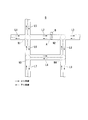
- FIG. 1 shows an example of a road network G according to an embodiment.
- the road network G includes a plurality of nodes N1, N2, N3,... (Hereinafter collectively referred to as node N) and a plurality of links L1, L2, L3,. ).
- the node N is an intersection or other nodal point on the expression of the road network G.
- the link L is a road section between two nodes N.
- the solid line arrow in the figure indicates an up lane.
- the arrow of the broken line in a figure shows a down lane.
- a beacon B is provided on the road side of the link L2.
- the beacon B is a device that transmits data including notification information to be notified to a vehicle passenger such as road traffic information in the road traffic information communication system. More specifically, the notification information includes information that is useful to passengers of vehicles traveling in either the up lane or the down lane. In that case, the beacon B transmits data including the notification information and the traveling direction information that specifies the traveling direction of the target vehicle to be notified of the notification information.
- beacons B may be provided on the road network G.
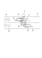
- FIG. 2 shows an example of a vehicle using a road traffic information communication system.
- a vehicle using the road traffic information communication system includes an in-vehicle device 110, a GPS receiver 130, and a display 150.
- the vehicle-mounted device 110 may be an example of the “traveling direction specifying device” in the present invention.
- the GPS receiver 130 is a device for positioning its own position using both radio navigation and self-contained navigation. More specifically, the GPS receiver 130 includes a GPS antenna, an accelerometer, and an angular velocity meter.
- the GPS antenna is an antenna that receives radio waves from GPS satellites.
- An accelerometer is a measuring instrument that measures changes in acceleration when a vehicle moves.
- the angular velocity meter is a measuring instrument that measures a change in angular velocity when the vehicle moves.
- the GPS receiver 130 is provided at a position where the GPS antenna is not shielded, such as on the dashboard D of the vehicle.
- the GPS receiver 130 is electrically connected to the vehicle-mounted device 110.
- the GPS receiver 130 uses the GPS radio navigation and the self-contained navigation using the accelerometer and the angular velocity meter to determine the position of the GPS receiver 130. Then, the GPS receiver 130 outputs data indicating the positioning result to the vehicle-mounted device 110.
- the in-vehicle device 110 is a device that performs data processing according to the traveling direction of the vehicle. More specifically, the vehicle-mounted device 110 includes an antenna and a light receiver. Here, the antenna is for receiving data transmitted from a radio beacon. The light receiver is for receiving data transmitted from an optical beacon. The vehicle-mounted device 110 is provided at a position where the antenna and the light receiver are not shielded, such as on the dashboard D of the vehicle. The vehicle-mounted device 110 is electrically connected to the GPS receiver 130 and the display 150. And the onboard equipment 110 will identify the link L in the road network G in which the vehicle exists by map-matching the positioning result shown by the data, if the input of the data output from the GPS receiver 130 is received. .
- the vehicle-mounted device 110 When the vehicle-mounted device 110 receives the data transmitted from the beacon B via the antenna or the light receiver, the first link L in which the vehicle exists in the road network G, and the first link.
- the traveling direction of the vehicle is specified based on the arrangement relationship with the second link L where the vehicle existed before entering L.
- the onboard equipment 110 determines whether the advancing direction designated with the advancing direction information contained in the data transmitted from the beacon B and the advancing direction of the specified vehicle correspond. When the two traveling directions match, the vehicle-mounted device 110 outputs data indicating the notification information included in the data transmitted from the beacon B to the display 150.
- the display 150 is a device that displays characters and figures. More specifically, the display 150 is provided at a position where the passenger can visually recognize, such as the center console C of the vehicle. The display 150 is electrically connected to the vehicle-mounted device 110. And display 150 will display the notice information shown by the data, if the input of the data outputted from onboard equipment 110 is received.
- the structure provided with the vehicle equipment 110, the GPS receiver 130, and the display 150 of one vehicle is demonstrated for the purpose of preventing that description becomes complicated.
- the vehicle may include a plurality of vehicle-mounted devices 110, a GPS receiver 130, and a display 150.
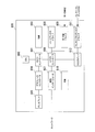
- FIG. 3 shows an example of a block configuration of the vehicle-mounted device 110.
- the in-vehicle device 110 includes a positioning data input receiving unit 111, a link specifying unit 112, a data receiving unit 114, a traveling direction specifying unit 113, a traveling direction determining unit 115, and a notification information output unit 116.
- a positioning data input receiving unit 111 receives positioning data from a positioning data input receiving unit 111
- a link specifying unit 112 receives a data from 111
- a data receiving unit 114 receives a data from a vehicle's direction specifying unit 113
- a traveling direction determining unit 115 includes a notification information output unit 116.
- the positioning data input receiving unit 111 receives input of data output from the GPS receiver 130.
- the link specifying unit 112 specifies a link in the road network G where the vehicle exists by map-matching the positioning result of the position of the vehicle by GPS.
- map matching is based on the premise that the vehicle runs on the road, and even if the positioning result is at a position other than the road, it is forcibly matched to the road (positioned travel route And the map data, the vehicle position is corrected on a nearby road even if the position is off the road.
- the data receiving unit 114 receives data including notification information to be notified to the vehicle occupant and traveling direction information for designating the traveling direction of the target vehicle to be notified of the notification information.
- the traveling direction specifying unit 113 arranges the first link L where the vehicle exists and the second link L where the vehicle existed before entering the first link L. Based on the relationship, the traveling direction of the vehicle is specified. More specifically, the traveling direction specifying unit 113 includes the first link L specified by the link specifying unit 112 and the second link specified by the link specifying unit 112 before entering the first link L. Based on the arrangement relationship with L, the traveling direction of the vehicle is specified.
- the traveling direction determination unit 115 determines whether or not the traveling direction specified by the traveling direction information included in the data received by the data receiving unit 114 matches the traveling direction specified by the traveling direction specifying unit 113. To do.
- the notification information output unit 116 outputs the notification information included in the data received by the data reception unit 114 when the traveling direction determination unit 115 determines that the two traveling directions match.
- FIG. 4 shows an example of the operation flow of the vehicle-mounted device 110.
- this operation flow a process for specifying the traveling direction of the vehicle will be described in detail.
- both FIGS. 1 to 3 are referred to.
- the GPS receiver 130 starts positioning of its own position. For example, the GPS receiver 130 repeatedly measures its position by using both GPS radio navigation and self-contained navigation using an accelerometer and an angular velocity meter. The GPS receiver 130 outputs data indicating the positioning result to the vehicle-mounted device 110 every time it measures its own position.
- the positioning data input receiving unit 111 of the vehicle-mounted device 110 receives an input of data output from the GPS receiver 130 (S101), the positioning data input receiving unit 111 sends the data to the link specifying unit 112.
- the link specifying unit 112 of the vehicle-mounted device 110 receives input of data sent from the positioning data input receiving unit 111, the positioning result of the position of the vehicle by GPS indicated by the data is map-matched with a digital map.
- the link L in the road network G where the vehicle exists is specified (S102).
- the plurality of links L shown in the digital map are associated with identification information for identifying the links L.
- the link specifying unit 112 specifies the link corresponding to the position obtained by map matching as the link L in the road network G where the vehicle exists.
- the link identification unit 112 identifies new links L on which the vehicle is traveling over time.
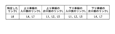
- the identification information of the specified link L as shown in FIG.
- the links L connected to the entrance side of the upstream lane of the link L6 are the link L4 and the link L7.
- the link L connected to the exit side of the up lane of the link L6 is the link L1, the link L2, and the link L5.
- the link L connected to the entrance side of the downlink lane of the link L6 is the link L1, the link L2, and the link L5.
- the link L connected to the exit side of the down lane of the link L6 is the link L4 and the link L7.
- the traveling direction specifying unit 113 of the vehicle-mounted device 110 specifies the traveling direction of the vehicle every time data received from the link specifying unit 112 is received (S103).
- a direction (link direction; positive direction) as the link is determined. That is, each end point of the link is defined as either a start point or an end point.
- the traveling direction of the vehicle is expressed as positive or negative with respect to the link direction of the link where the vehicle exists (first link).
- the traveling direction specifying unit 113 determines whether the second link (link where the vehicle existed before entering the first link) is connected to the start point or the end point of the first link, and the vehicle Is determined from the approach direction of the vehicle to the first link.
- the traveling direction of the vehicle is determined to be “positive”.
- the traveling direction identification unit 113 identifies the lane in the traveling direction of the vehicle on the link L.
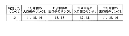
- the traveling direction specifying unit 113 receives the data specifying the position of the vehicle as the link L6 as shown in FIG. 5, and then specifies the data specifying the position of the vehicle as the link L2 as shown in FIG. Suppose you receive it. In that case, the vehicle is moving from the link L6 to the link L2. In other words, the vehicle is moving in the lane where the link L6 is connected to the entrance side of the link L2.
- the traveling direction identification unit 113 identifies the lane in the traveling direction of the link L2 in which the link L on the entrance side is the link L6 with reference to the data shown in FIG. In this case, the traveling direction identifying unit 113 identifies the traveling direction of the vehicle as being an upstream lane of the link L2.
- the in-vehicle device 110 repeatedly performs the processes of steps S101 to S103 described above. In this way, the vehicle-mounted device 110 can accurately specify the traveling direction of the vehicle.
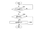
- FIG. 7 shows an example of the operation flow of the vehicle-mounted device 110.
- processing when data is received from beacon B will be described in detail.
- both FIGS. 1 to 6 are referred to.
- the data receiving unit 114 of the vehicle-mounted device 110 receives the data transmitted from the beacon B (S201: Yes). Then, the data receiving unit 114 sends data notifying that the data has been received to the traveling direction specifying unit 113 and also sending data indicating the traveling direction information included in the received data to the traveling direction determining unit 115. The data indicating the notification information included in the received data is sent to the notification information output unit 116.
- the traveling direction specifying unit 113 of the vehicle-mounted device 110 receives the data transmitted from the data receiving unit 114, the traveling direction identifying unit 113 transmits data indicating the latest traveling direction of the vehicle identified so far to the traveling direction determining unit 115.
- the traveling direction determination unit 115 of the vehicle-mounted device 110 receives the data transmitted from the data receiving unit 114 and the traveling direction specifying unit 113, respectively, the traveling direction indicated by the data received from the data receiving unit 114 and the traveling direction specifying It is determined whether or not the traveling direction indicated by the data received from the unit 113 matches (S203). Then, the traveling direction identification unit 113 sends data indicating the determination result to the notification information output unit 116.
- the notification information output unit 116 of the vehicle-mounted device 110 receives the data sent from the data receiving unit 114. Then, the notification information output unit 116 receives the data sent from the traveling direction determination unit 115. If the determination result indicated by the data is a determination result that the two traveling directions match (S203: Yes), the notification information output unit 116 uses the data received from the data reception unit 114. The notification information shown is output and displayed on the display 150 (S204). On the other hand, when the determination result indicated by the data received from the traveling direction determination unit 115 is a determination result that the two traveling directions do not match (S203: No), the notification information output unit 116 receives the data The data received from the unit 114 is discarded and no information is displayed on the display 150.
- the vehicle occupant can acquire only useful information according to the traveling direction of the vehicle.
- the vehicle-mounted device 110 includes, in the road network G, the first link L where the vehicle exists, and the second link where the vehicle existed before entering the first link L.
- the traveling direction of the vehicle is specified based on the arrangement relationship with the link.
- the traveling direction of the vehicle can be accurately specified without incurring costs.
- the vehicle-mounted device 110 specifies the link L in the road network G where the vehicle exists by map-matching the positioning result of the position of the vehicle by GPS. And the onboard equipment 110 specifies the advancing direction of a vehicle based on the arrangement
- the vehicle-mounted device 110 receives data including notification information to be notified to the vehicle occupant and traveling direction information for designating the traveling direction of the target vehicle to be notified of the notification information. To do. And the onboard equipment 110 determines whether the advancing direction designated by the advancing direction information contained in the received data and the specified advancing direction correspond. And the onboard equipment 110 outputs the notification information contained in the received data, when two traveling directions correspond.
- the vehicle occupant can acquire only useful information according to the traveling direction of the vehicle.
- the on-vehicle device 110 has been described as an example of the “traveling direction specifying device” in the present invention.
- the “traveling direction identifying device” in the present invention is not limited to the vehicle-mounted device 110.
- the “traveling direction specifying device” in the present invention may be a DSRC (Dedicated Short Range Communication) roadside wireless device.
- FIG. 8 shows an example of a hardware configuration of a computer 800 that constitutes the vehicle-mounted device 110 according to the present embodiment.
- a computer 800 includes a CPU (Central Processing Unit) 802, a RAM (Random Access Memory) 803, a graphic controller 804, and a display 805 that are mutually connected by a host controller 801, and input / output An input / output unit having a communication interface 807, a hard disk drive 808, and a CD-ROM (Compact Disk Only Memory) drive 809 connected to each other by the controller 806, and a ROM (Read Only Memory) connected to the input / output controller 806 810, legacy input / output having flexible disk drive 811 and input / output chip 812 Provided with a door.
- a CPU Central Processing Unit
- RAM Random Access Memory
- FIG. 8 shows an example of a hardware configuration of a computer 800 that constitutes the vehicle-mounted device 110 according to the present embodiment.
- a computer 800 includes a CPU (Central Processing Unit) 802, a RAM (Ran
- the host controller 801 connects the RAM 803, the CPU 802 that accesses the RAM 803 at a high transfer rate, and the graphic controller 804.
- the CPU 802 operates based on programs stored in the ROM 810 and the RAM 803 and controls each unit.
- the graphic controller 804 acquires image data generated on a frame buffer provided in the RAM 803 by the CPU 802 and the like and displays the image data on the display 805.
- the graphic controller 804 may include a frame buffer for storing image data generated by the CPU 802 or the like.
- the input / output controller 806 connects the host controller 801 to the communication interface 807, the hard disk drive 808, and the CD-ROM drive 809, which are relatively high-speed input / output devices.
- the hard disk drive 808 stores programs and data used by the CPU 802 in the computer 800.
- the CD-ROM drive 809 reads a program or data from the CD-ROM 892 and provides it to the hard disk drive 808 via the RAM 803.
- the input / output controller 806 is connected to the ROM 810, the flexible disk drive 811 and the input / output chip 812, which are relatively low-speed input / output devices.
- the ROM 810 stores a boot program that is executed when the computer 800 is started and / or a program that depends on the hardware of the computer 800.
- the flexible disk drive 811 reads a program or data from the flexible disk 893 and provides it to the hard disk drive 808 via the RAM 803.
- the input / output chip 812 connects the flexible disk drive 811 to the input / output controller 806 and connects various input / output devices to the input / output controller 806 via, for example, a parallel port, serial port, keyboard port, mouse port, and the like. To do.
- the program provided to the hard disk drive 808 via the RAM 803 is stored in a recording medium such as a flexible disk 893, a CD-ROM 892, or an IC (Integrated Circuit) card and provided by the user.
- the program is read from the recording medium, installed in the hard disk drive 808 in the computer 800 via the RAM 803, and executed by the CPU 802.
- a program that is installed in the computer 800 and causes the computer 800 to function as the vehicle-mounted device 110 includes the first link L in which the vehicle exists in the road network G and the first link L in step S103. Based on the arrangement relationship with the second link L where the vehicle existed before entering the vehicle, the vehicle is caused to function as a traveling direction identifying unit 113 that identifies the traveling direction of the vehicle.
- the program includes a link specifying unit 112 that specifies the link L in the road network G in which the vehicle exists by map-matching the positioning result of the position of the vehicle by GPS in step S102.
- a link specifying unit 112 that specifies the link L in the road network G in which the vehicle exists by map-matching the positioning result of the position of the vehicle by GPS in step S102.
- step S103 based on the arrangement relationship between the first link L specified by the specifying unit 112 and the second link L specified by the link specifying unit 112 before entering the first link L, You may make it function as the advancing direction specific
- the program includes data including notification information for notifying the vehicle 800 to the vehicle occupant in step S201, and traveling direction information for designating the traveling direction of the target vehicle to be notified of the notification information.
- traveling direction information for designating the traveling direction of the target vehicle to be notified of the notification information.
- the information processing described in these programs is read by the computer 800, whereby the positioning data input receiving unit 111, the link specifying unit 112, which are specific means in which the software and the various hardware resources described above cooperate with each other, It functions as a data receiving unit 114, a traveling direction specifying unit 113, a traveling direction determining unit 115, and a notification information output unit 116.
- the specific vehicle equipment 110 according to the intended purpose is constructed
- the CPU 802 executes a communication program loaded on the RAM 803 and executes a communication interface based on the processing content described in the communication program.
- a communication process is instructed to 807.
- the communication interface 807 reads transmission data stored in a transmission buffer area or the like provided on a storage device such as the RAM 803, the hard disk drive 808, the flexible disk 893, or the CD-ROM 892, and sends it to the network.
- the reception data transmitted or received from the network is written into a reception buffer area or the like provided on the storage device.
- the communication interface 807 may transfer transmission / reception data to / from the storage device by the direct memory access method. Instead, the CPU 802 reads data from the transfer source storage device or the communication interface 807.
- the transmission / reception data may be transferred by writing the data to the transfer destination communication interface 807 or the storage device.
- the CPU 802 transfers all or a necessary portion of the files or database stored in the external storage device such as the hard disk drive 808, CD-ROM 892, and flexible disk 893 to the RAM 803 by direct memory access transfer or the like.
- the data is read and various processes are performed on the data on the RAM 803. Then, the CPU 802 writes the processed data back to the external storage device by direct memory access transfer or the like.
- the RAM 803 can be regarded as temporarily holding the contents of the external storage device, in the present embodiment, the RAM 803 and the external storage device are collectively referred to as a memory, a storage unit, or a storage device. .
- Various types of information such as various programs, data, tables, and databases in the present embodiment are stored on such a storage device and are subjected to information processing.
- the CPU 802 can hold a part of the RAM 803 in the cache memory and perform reading and writing on the cache memory. Even in such a form, the cache memory bears a part of the function of the RAM 803. Therefore, in the present embodiment, the cache memory is also included in the RAM 803, the memory, and / or the storage device unless otherwise indicated. To do.
- the CPU 802 performs various operations, such as various operations, information processing, condition determination, information retrieval, replacement, and the like described in the present embodiment for data read from the RAM 803 and specified by a command sequence of the program. Is written back to the RAM 803. For example, when performing the condition determination, the CPU 802 satisfies the conditions such that the various variables shown in the present embodiment are larger, smaller, above, below, or equal to other variables or constants. If the condition is satisfied or not satisfied, the program branches to a different instruction sequence or calls a subroutine.
- the CPU 802 can search for information stored in a file in a storage device or a database. For example, when a plurality of entries in which the attribute value of the second attribute is associated with the attribute value of the first attribute are stored in the storage device, the CPU 802 stores the plurality of entries stored in the storage device. The entry that matches the condition in which the attribute value of the first attribute is specified is retrieved, and the attribute value of the second attribute that is stored in the entry is read, thereby associating with the first attribute that satisfies the predetermined condition The attribute value of the specified second attribute can be obtained.
- the programs or modules shown above may be stored in an external storage medium.
- a storage medium in addition to a flexible disk 893 and a CD-ROM 892, an optical recording medium such as a DVD (Digital Versatile Disk) or a CD (Compact Disk), a magneto-optical recording medium such as an MO (Magneto-Optical disk), or a tape
- a storage medium such as a hard disk or RAM provided in a server system connected to a dedicated communication network or the Internet may be used as a recording medium, and the program may be provided to the computer 800 via the network.
- the present invention is applied to a traveling direction identifying system that identifies the traveling direction of a vehicle, a traveling direction identifying method, a traveling direction identifying device, a program that causes a computer to function as the traveling direction identifying device, and a recording medium that records the program. Can do.
Landscapes
- Engineering & Computer Science (AREA)
- Radar, Positioning & Navigation (AREA)
- Remote Sensing (AREA)
- Physics & Mathematics (AREA)
- General Physics & Mathematics (AREA)
- Automation & Control Theory (AREA)
- Navigation (AREA)
- Traffic Control Systems (AREA)
- Indicating Or Recording The Presence, Absence, Or Direction Of Movement (AREA)
Abstract
車両の進行方向を特定する進行方向特定装置を備え、進行方向特定装置は、道路網(G)において、車両が存在している第1のリンク(L)と、当該第1のリンク(L)へ進入する前に車両が存在していた第2のリンク(L)との配置関係に基づいて、車両の進行方向を特定する進行方向特定部を備える。
Description
本発明は、進行方向特定システム、進行方向特定方法、進行方向特定装置、プログラム、及び記録媒体に関する。本願は、2012年12月20日に、日本に出願された特願2012-278496号に基づき優先権を主張し、その内容をここに援用する。
道路交通情報通信システムにおいては、渋滞、工事、事故、通行規制、駐車場、旅行時間、緊急メッセージ等の道路交通に係る様々な情報を収集して、提供している。
これらの情報は、道路交通情報通信システムセンターへ集められて、編集された後、電波ビーコン、光ビーコン、FM(Frequency Modulation)多重放送等の方式を使ってユーザへ届けられる。電波ビーコンや光ビーコンは、道路上に設置されて、その道路に関連する情報を中心に提供している。
このような仕組みによって提供される道路交通情報通信システムの情報は、所定時間毎に最新の情報に更新される。つまり、道路交通情報通信システムにおいては、渋滞情報等を搭乗者が入手できることにより、渋滞している道の回避、高速道路の利用区間の変更等、利用する道路を選択したり、目的地までの到着時間を予想したりすることができる。
ここで、道路交通情報通信システムの情報は、上下車線のうち、いずれか一方の車線を走行している車両の搭乗者にのみ有用な内容であることも多い。例えば、上り車線の渋滞情報等は、上り車線を走行している車両の搭乗者にのみ有用な内容であり、下り車線を走行している車両の搭乗者にとっては不要な内容である。
したがって、このような内容の情報は、対象車線を走行している車両にのみ配信することが望ましい。しかしながら、電波ビーコンや光ビーコンによっては、いずれか一方の車線の範囲内にのみ情報を送信することが難しい。
そこで、これらの問題を解決する方法としては、車両に設けられた受信装置が情報を受信した場合に、車両の進行方向を特定して、その進行方向に対して有用な情報のみを搭乗者に提供するといったことが考えられる。このような背景に関連する技術としては、様々なものが知られている(例えば、特許文献1参照。)。
例えば、特許文献1には、移動体に搭載される運動状態判定装置が記載されている。より具体的に説明すると、この装置は、移動体の地球上の位置を検出する。また、この装置は、移動体の方位を検出する。そして、この装置は、これらの検出結果に基づいて、移動体の運動状態を判定する。このようにして、この装置によっては、例えばエンジンの動作状態や車輪の速度等の移動体自身の情報を用いて運動状態を判定する技術的構成を採用していないので、移動体の運動状態を高い精度で判定できる。
特許文献1に記載の装置は、GPS受信機が今回検出した車両の位置と、前回に検出した車両の位置との差から車両の進行方向を算出している。しかしながら、GPSによる測位は、誤差を生じる。そのため、このような方法によっては、必ずしも車両の進行方向を正確に算出することができない。
例えば、図9を用いて説明すると、ビーコンBから送信される情報は、道路Rの方向D1の車線を走行している車両の搭乗者にのみ有用な情報であるとする。換言すれば、ビーコンBにて送信される情報は、道路Rの方向D2の車線を走行している車両の搭乗者にとっては不要な情報であるとする。
ここで、車線を走行している車両VaがビーコンBの無線通信範囲A内に進入したとき、車両VaのGPS受信機は、車両Vaの位置として、測位位置C2を検出したとする。
また、車両VaのGPS受信機は、測位位置C2を検出する前の車両Vaの位置として、測位位置C1を検出していたものとする。その場合、特許文献1の方法によっては、車両Vaの進行方向が方向D1であるにも拘らず、車両Vaの進行方向を方向D2であると算出してしまい、ビーコンBから送信された情報が搭乗者に提供されない。
また、車両VaのGPS受信機は、測位位置C2を検出する前の車両Vaの位置として、測位位置C1を検出していたものとする。その場合、特許文献1の方法によっては、車両Vaの進行方向が方向D1であるにも拘らず、車両Vaの進行方向を方向D2であると算出してしまい、ビーコンBから送信された情報が搭乗者に提供されない。
一方、車線を走行している車両VbがビーコンBの無線通信範囲A内に進入したとき、車両VbのGPS受信機は、車両Vbの位置として、測位位置C3を検出したとする。また、車両Vbの受信機は、測位位置C3を検出する前の車両Vbの位置として、測位位置C4を検出していたものとする。その場合、特許文献1の方法によっては、車両Vbの進行方向が方向D2であるにも拘らず、車両Vbの進行方向を方向D1であると算出してしまい、ビーコンBから送信された不要な情報が搭乗者に提供されてしまう。
また、特許文献1に記載の装置は、地磁気センサからの情報に基づいて車両の向きを算出している。しかしながら、地磁気センサを用いる方法は、高コストとなり、あまり現実的でない。そこで、車両の進行方向を精確に特定するにあたっては、低コストであることが望まれる。
上記課題を解決するために、本発明の第1の形態によると、車両の進行方向を特定する進行方向特定システムであって、車両の進行方向を特定する進行方向特定装置を備え、進行方向特定装置は、道路網において、車両が存在している第1のリンクと、当該第1のリンクへ進入する前に車両が存在していた第2のリンクとの配置関係に基づいて、車両の進行方向を特定する進行方向特定部を備える。
進行方向特定装置は、GPSによる車両の位置の測位結果をマップマッチングして、車両が存在している道路網におけるリンクを特定するリンク特定部を更に備え、進行方向特定部は、リンク特定部が特定した第1のリンクと、当該第1のリンクへ進入する前にリンク特定部が特定した第2のリンクとの配置関係に基づいて、車両の進行方向を特定してよい。
進行方向特定装置は、車両の搭乗者に対して通知する通知情報と、当該通知情報を通知すべき対象の車両の進行方向を指定する進行方向情報とを含むデータを受信するデータ受信部と、データ受信部が受信したデータに含まれる進行方向情報によって指定されている進行方向と、進行方向特定部が特定した進行方向とが一致しているか否かを判定する進行方向判定部と、2つの進行方向が一致していると進行方向判定部が判定した場合に、データ受信部が受信したデータに含まれる通知情報を出力する通知情報出力部とを更に備えてよい。
本発明の第2の形態によると、車両の進行方向を特定する進行方向特定方法であって、道路網において、車両が存在している第1のリンクと、当該第1のリンクへ進入する前に車両が存在していた第2のリンクとの配置関係に基づいて、車両の進行方向を特定する進行方向特定段階を備える。
本発明の第3の形態によると、車両の進行方向を特定する進行方向特定装置であって、道路網において、車両が存在している第1のリンクと、当該第1のリンクへ進入する前に車両が存在していた第2のリンクとの配置関係に基づいて、車両の進行方向を特定する進行方向特定部を備える。
本発明の第4の形態によると、車両の進行方向を特定する進行方向特定装置として、コンピュータを機能させるプログラムであって、コンピュータを、道路網において、車両が存在している第1のリンクと、当該第1のリンクへ進入する前に車両が存在していた第2のリンクとの配置関係に基づいて、車両の進行方向を特定する進行方向特定部として機能させる。
本発明の第5の形態によると、車両の進行方向を特定する進行方向特定装置として、コンピュータを機能させるプログラムを記録した記録媒体であって、コンピュータを、道路網において、車両が存在している第1のリンクと、当該第1のリンクへ進入する前に車両が存在していた第2のリンクとの配置関係に基づいて、車両の進行方向を特定する進行方向特定部として機能させるプログラムを記録した。
なおまた、上記の発明の概要は、本発明の必要な特徴の全てを列挙したものではない。また、これらの特徴群のサブコンビネーションもまた、発明となり得る。
以上の説明から明らかなように、この発明によっては、コストを掛けることなく、車両の進行方向を正確に特定することができる。
以下、発明の実施の形態を通じて本発明を説明するが、以下の実施形態は特許請求の範囲にかかる発明を限定するものではなく、また、実施形態の中で説明されている特徴の組み合わせの全てが発明の解決手段に必須であるとは限らない。
図1は、一実施形態に係る道路網Gの一例を示す。道路網Gは、複数のノードN1、N2、N3、・・・(以下、ノードNと総称する。)と、複数のリンクL1、L2、L3、・・・(以下、リンクLと総称する。)の組み合わせによって成る。ここで、ノードNとは、交差点、その他、道路網Gの表現上の結節点等である。また、リンクLとは、2つのノードNの間の道路区間である。なおまた、図中の実線の矢印は、上り車線を示す。また、図中の破線の矢印は、下り車線を示す。
リンクL2の路側には、ビーコンBが設けられている。ビーコンBは、道路交通情報通信システムにおける道路交通情報等の車両の搭乗者に対して通知する通知情報を含むデータを送信する装置である。より具体的に説明すると、通知情報には、上り車線、又は下り車線のいずれか一方の車線を走行している車両の搭乗者に対して有用な情報もある。その場合、ビーコンBは、通知情報と、その通知情報を通知すべき対象の車両の進行方向を指定する進行方向情報とを含むデータを送信する。
なおまた、本実施形態においては、説明が煩雑になることを防ぐことを目的として、道路網Gに一のビーコンBが設けられている例について説明する。しかしながら、道路網Gには、複数のビーコンBが設けられていてよい。
図2は、道路交通情報通信システムを利用する車両の一例を示す。道路交通情報通信システムを利用する車両は、車載器110、GPS受信機130、及びディスプレイ150を備える。なおまた、車載器110は、この発明における「進行方向特定装置」の一例であってよい。
GPS受信機130は、電波航法と自立航法とを併用して自位置を測位する装置である。より具体的に説明すると、GPS受信機130は、GPSアンテナ、加速度計、及び角速度計を備える。ここで、GPSアンテナとは、GPS衛星からの電波を受信するアンテナである。また、加速度計とは、車両が移動する際の加速度変化を計測する計測器である。また、角速度計とは、車両が移動する際の角速度変化を計測する計測器である。GPS受信機130は、例えば、車両のダッシュボードDの上等のような、GPSアンテナが遮蔽されない位置に設けられている。そして、GPS受信機130は、車載器110と電気的に接続されている。そして、GPS受信機130は、GPSによる電波航法と、加速度計、及び角速度計を用いた自立航法とを併用して自位置を測位する。そして、GPS受信機130は、その測位結果を示すデータを、車載器110へ出力する。
車載器110は、車両の進行方向に応じたデータ処理を行う装置である。より具体的に説明すると、車載器110は、アンテナ、及び受光器を備える。ここで、アンテナとは、電波ビーコンから送信されたデータを受信するためのものである。また、受光器とは、光ビーコンから送信されたデータを受信するためのものである。車載器110は、例えば、車両のダッシュボードDの上等のような、アンテナ、及び受光器が遮蔽されない位置に設けられている。そして、車載器110は、GPS受信機130、及びディスプレイ150と電気的に接続されている。そして、車載器110は、GPS受信機130から出力されたデータの入力を受け付けると、そのデータによって示される測位結果をマップマッチングして、車両が存在している道路網GにおけるリンクLを特定する。そして、車載器110は、ビーコンBから送信されたデータを、アンテナ、又は受光器を介して受信すると、道路網Gにおいて、車両が存在している第1のリンクLと、その第1のリンクLへ進入する前に車両が存在していた第2のリンクLとの配置関係に基づいて、車両の進行方向を特定する。そして、車載器110は、ビーコンBから送信されたデータに含まれている進行方向情報によって指定されている進行方向と、特定した車両の進行方向とが一致しているか否かを判定する。そして、2つの進行方向が一致している場合、車載器110は、ビーコンBから送信されたデータに含まれている通知情報を示すデータを、ディスプレイ150へ出力する。
ディスプレイ150は、文字や図形を表示する装置である。より具体的に説明すると、ディスプレイ150は、例えば、車両のセンターコンソールC等のような、搭乗者が視認し得る位置に設けられている。そして、ディスプレイ150は、車載器110と電気的に接続されている。そして、ディスプレイ150は、車載器110から出力されたデータの入力を受け付けると、そのデータによって示される通知情報を表示する。
なおまた、本実施形態においては、説明が煩雑になることを防ぐことを目的として、車両が一の車載器110、GPS受信機130、及びディスプレイ150を備える構成について説明する。しかしながら、車両は、複数の車載器110、GPS受信機130、及びディスプレイ150を備えてよい。
図3は、車載器110のブロック構成の一例を示す。車載器110は、測位データ入力受付部111、リンク特定部112、データ受信部114、進行方向特定部113、進行方向判定部115、及び通知情報出力部116を有する。以下の説明においては、各構成要素の機能、及び動作を詳述する。
測位データ入力受付部111は、GPS受信機130から出力されたデータの入力を受け付ける。
リンク特定部112は、GPSによる車両の位置の測位結果をマップマッチングして、車両が存在している道路網Gにおけるリンクを特定する。ここで、マップマッチングとは、車両は道路の上を走るものだという前提を持って、たとえ測位結果が道路以外の位置であろうとも、強制的に道路の上に合わせる(測位された走行経路と、地図データとを照合して、位置が道路からずれている場合でも、車両位置を近くの道路上に補正する。)処理である。
データ受信部114は、車両の搭乗者に対して通知する通知情報と、その通知情報を通知すべき対象の車両の進行方向を指定する進行方向情報とを含むデータを受信する。
進行方向特定部113は、道路網Gにおいて、車両が存在している第1のリンクLと、その第1のリンクLへ進入する前に車両が存在していた第2のリンクLとの配置関係に基づいて、車両の進行方向を特定する。より具体的に説明すると、進行方向特定部113は、リンク特定部112が特定した第1のリンクLと、その第1のリンクLへ進入する前にリンク特定部112が特定した第2のリンクLとの配置関係に基づいて、車両の進行方向を特定する。
進行方向判定部115は、データ受信部114が受信したデータに含まれる進行方向情報によって指定されている進行方向と、進行方向特定部113が特定した進行方向とが一致しているか否かを判定する。
通知情報出力部116は、2つの進行方向が一致していると進行方向判定部115が判定した場合に、データ受信部114が受信したデータに含まれる通知情報を出力する。
図4は、車載器110の動作フローの一例を示す。この動作フローにおいては、車両の進行方向を特定する処理について詳述する。なおまた、この動作フローの説明においては、図1から図3を共に参照する。
車両の原動機が始動すると、GPS受信機130は、自位置の測位を開始する。例えば、GPS受信機130は、GPSによる電波航法と、加速度計、及び角速度計を用いた自立航法とを併用して、自位置を繰り返し測位する。そして、GPS受信機130は、自位置を測位する度に、その測位結果を示すデータを、車載器110へ出力する。
車載器110の測位データ入力受付部111は、GPS受信機130から出力されたデータの入力を受け付けると(S101)、そのデータを、リンク特定部112へ送る。
車載器110のリンク特定部112は、測位データ入力受付部111から送られたデータの入力を受け付ける度に、そのデータによって示されるGPSによる車両の位置の測位結果を、デジタル地図にマップマッチングして、車両が存在している道路網GにおけるリンクLを特定する(S102)。ここで、デジタル地図に示されている複数のリンクLには、そのリンクLを識別するための識別情報が対応付けられている。リンク特定部112は、マップマッチングして得られた位置に該当するリンクを、車両が存在している道路網GにおけるリンクLとして特定する。車両が走行している場合、リンク特定部112は、車両が走行している新たなリンクLを経時的に特定していくことになる。リンク特定部112は、新たなリンクを特定する度に、図5、及び図6に示すような、特定したリンクLの識別情報と共に、特定したリンクLの上り車線、及び下り車線の入口側にそれぞれ接続されているリンクLの識別情報と、特定したリンクLの上り車線、及び下り車線の出口側にそれぞれ接続されているリンクLの識別情報とを含むデータを、進行方向特定部113へ送る。例えば、図1に示す道路網Gの場合、リンクL6の上り車線の入口側に接続されているリンクLは、リンクL4、及びリンクL7である。また、リンクL6の上り車線の出口側に接続されているリンクLは、リンクL1、リンクL2、及びリンクL5である。
また、リンクL6の下り車線の入口側に接続されているリンクLは、リンクL1、リンクL2、及びリンクL5である。また、リンクL6の下り車線の出口側に接続されているリンクLは、リンクL4、及びリンクL7である。
また、リンクL6の下り車線の入口側に接続されているリンクLは、リンクL1、リンクL2、及びリンクL5である。また、リンクL6の下り車線の出口側に接続されているリンクLは、リンクL4、及びリンクL7である。
車載器110の進行方向特定部113は、リンク特定部112から送られたデータを受け取る度に、車両の進行方向を特定する(S103)。ここで、マップデータの各リンクにおいては、そのリンクとしての方向(リンク方向;正方向)が定められている。即ち、リンクの各端点は、始点及び終点のいずれかとして定められている。車両の進行方向は、車両が存在しているリンク(第1のリンク)のリンク方向に対する正負で表現される。進行方向特定部113は、第2のリンク(第1のリンクへ進入する前に車両が存在していたリンク)が、第1のリンクの始点及び終点のどちらに繋がっているかを判定し、車両の進行方向を、第1のリンクへの車両の進入方向から特定する。例えば、第2のリンクが第1のリンクの始点に繋がっていれば、車両の進行方向を”正”と判断する。例えば、進行方向特定部113は、リンクLにおける車両の進行方向の車線を特定する。ここで、進行方向特定部113は、図5に示すような、車両の位置をリンクL6として特定するデータを受け取った後に、図6に示すような、車両の位置をリンクL2として特定するデータを受け取ったとする。その場合、車両は、リンクL6からリンクL2へ移動していることになる。換言すれば、車両は、リンクL2の入口側にリンクL6が接続されている車線を移動していることになる。したがって、進行方向特定部113は、図6に示すデータを参照して、入口側のリンクLがリンクL6であるリンクL2の進行方向の車線を特定する。この場合、進行方向特定部113は、車両の進行方向を、リンクL2の上り車線であると特定する。
車載器110は、上述したステップS101~S103の処理を繰り返し行う。このようにして、車載器110は、車両の進行方向を正確に特定することができる。
図7は、車載器110の動作フローの一例を示す。この動作フローにおいては、ビーコンBからデータを受信したときの処理について詳述する。なおまた、この動作フローの説明においては、図1から図6を共に参照する。
ビーコンBの無線通信範囲A内に車両が進入すると、車載器110のデータ受信部114は、ビーコンBから送信されているデータを受信する(S201:Yes)。そして、データ受信部114は、データを受信したことを通知するデータを、進行方向特定部113へ送ると共に、受信したデータに含まれている進行方向情報を示すデータを進行方向判定部115へ送り、受信したデータに含まれている通知情報を示すデータを通知情報出力部116へ送る。
車載器110の進行方向特定部113は、データ受信部114から送られたデータを受け取ると、それまでに特定した最新の車両の進行方向を示すデータを、進行方向判定部115へ送る。
車載器110の進行方向判定部115は、データ受信部114、及び進行方向特定部113から送られたデータをそれぞれ受け取ると、データ受信部114から受け取ったデータによって示される進行方向と、進行方向特定部113から受け取ったデータによって示される進行方向とが一致しているか否かを判定する(S203)。そして、進行方向特定部113は、その判定結果を示すデータを、通知情報出力部116へ送る。
車載器110の通知情報出力部116は、データ受信部114から送られたデータを受け取る。そして、通知情報出力部116は、進行方向判定部115から送られたデータを受け取る。そして、そのデータによって示される判定結果が、2つの進行方向が一致しているとの判定結果であった場合(S203:Yes)、通知情報出力部116は、データ受信部114から受け取ったデータによって示される通知情報をディスプレイ150に出力して表示させる(S204)。一方、進行方向判定部115から受け取ったデータによって示される判定結果が、2つの進行方向が一致していないとの判定結果であった場合(S203:No)、通知情報出力部116は、データ受信部114から受け取ったデータを破棄して、ディスプレイ150に何ら情報を表示させない。
このようにして、車両の搭乗者は、車両の進行方向に応じて、有用な情報のみを取得することができる。
以上、説明したように、車載器110は、道路網Gにおいて、車両が存在している第1のリンクLと、その第1のリンクLへ進入する前に車両が存在していた第2のリンクとの配置関係に基づいて、車両の進行方向を特定する。
このようにして、車載器110によっては、コストを掛けることなく、車両の進行方向を正確に特定することができる。
また、上述したように、車載器110は、GPSによる車両の位置の測位結果をマップマッチングして、車両が存在している道路網GにおけるリンクLを特定する。そして、車載器110は、特定した第1のリンクと、その第1のリンクへ進入する前に特定した第2のリンクとの配置関係に基づいて、車両の進行方向を特定する。
このようにして、車載器110によっては、GPSを利用しているにも拘らず、GPSの誤差の影響を受けることなく、車両の進行方向を正確に特定することができる。
また、上述したように、車載器110は、車両の搭乗者に対して通知する通知情報と、その通知情報を通知すべき対象の車両の進行方向を指定する進行方向情報とを含むデータを受信する。そして、車載器110は、受信したデータに含まれる進行方向情報によって指定されている進行方向と、特定した進行方向とが一致しているか否かを判定する。そして、車載器110は、2つの進行方向が一致している場合に、受信したデータに含まれる通知情報を出力する。
このようにして、車両の搭乗者は、車両の進行方向に応じて、有用な情報のみを取得することができる。
なおまた、上述した実施形態においては、この発明における「進行方向特定装置」の一例として、車載器110を例にとって説明した。しかしながら、この発明における「進行方向特定装置」は、車載器110に限られない。例えば、この発明における「進行方向特定装置」は、DSRC(Dedicated Short Range Communication)路側無線装置であってもよい。
図8は、本実施形態に係る車載器110を構成するコンピュータ800のハードウェア構成の一例を示す。本実施形態に係るコンピュータ800は、ホストコントローラ801により相互に接続されるCPU(Central Processing Unit)802、RAM(Random Access Memory)803、グラフィックコントローラ804、及びディスプレイ805を有するCPU周辺部と、入出力コントローラ806により相互に接続される通信インターフェース807、ハードディスクドライブ808、及びCD-ROM(Compact Disk Read Only Memory)ドライブ809を有する入出力部と、入出力コントローラ806に接続されるROM(Read Only Memory)810、フレキシブルディスクドライブ811、及び入出力チップ812を有するレガシー入出力部とを備える。
ホストコントローラ801は、RAM803と、高い転送レートでRAM803をアクセスするCPU802、及びグラフィックコントローラ804とを接続する。CPU802は、ROM810、及びRAM803に格納されたプログラムに基づいて動作し、各部の制御を行う。グラフィックコントローラ804は、CPU802等がRAM803内に設けたフレームバッファ上に生成する画像データを取得し、ディスプレイ805上に表示させる。これに代えて、グラフィックコントローラ804は、CPU802等が生成する画像データを格納するフレームバッファを、内部に含んでもよい。
入出力コントローラ806は、ホストコントローラ801と、比較的高速な入出力装置である通信インターフェース807、ハードディスクドライブ808、及びCD-ROMドライブ809を接続する。ハードディスクドライブ808は、コンピュータ800内のCPU802が使用するプログラム、及びデータを格納する。CD-ROMドライブ809は、CD-ROM892からプログラム、又はデータを読み取り、RAM803を介してハードディスクドライブ808に提供する。
また、入出力コントローラ806には、ROM810と、フレキシブルディスクドライブ811、及び入出力チップ812の比較的低速な入出力装置とが接続される。ROM810は、コンピュータ800が起動時に実行するブートプログラム、及び/又はコンピュータ800のハードウェアに依存するプログラム等を格納する。フレキシブルディスクドライブ811は、フレキシブルディスク893からプログラム、又はデータを読み取り、RAM803を介してハードディスクドライブ808に提供する。入出力チップ812は、フレキシブルディスクドライブ811を入出力コントローラ806へと接続すると共に、例えばパラレルポート、シリアルポート、キーボードポート、マウスポート等を介して各種の入出力装置を入出力コントローラ806へと接続する。
RAM803を介してハードディスクドライブ808に提供されるプログラムは、フレキシブルディスク893、CD-ROM892、又はIC(Integrated Circuit)カード等の記録媒体に格納されて利用者によって提供される。プログラムは、記録媒体から読み出され、RAM803を介してコンピュータ800内のハードディスクドライブ808にインストールされ、CPU802において実行される。
コンピュータ800にインストールされ、コンピュータ800を車載器110として機能させるプログラムは、コンピュータ800を、ステップS103において、道路網Gにおいて、車両が存在している第1のリンクLと、その第1のリンクLへ進入する前に車両が存在していた第2のリンクLとの配置関係に基づいて、車両の進行方向を特定する進行方向特定部113として機能させる。
更に、当該プログラムは、コンピュータ800を、ステップS102において、GPSによる車両の位置の測位結果をマップマッチングして、車両が存在している道路網GにおけるリンクLを特定するリンク特定部112と、リンク特定部112が特定した第1のリンクLと、その第1のリンクLへ進入する前にリンク特定部112が特定した第2のリンクLとの配置関係に基づいて、ステップS103において、車両の進行方向を特定する進行方向特定部113として機能させてもよい。
更に、当該プログラムは、コンピュータ800を、ステップS201において、車両の搭乗者に対して通知する通知情報と、その通知情報を通知すべき対象の車両の進行方向を指定する進行方向情報とを含むデータを受信するデータ受信部114と、データ受信部114が受信したデータに含まれる進行方向情報によって指定されている進行方向と、進行方向特定部113が特定した進行方向とが一致しているか否かを、ステップS203において判定する進行方向判定部115と、2つの進行方向が一致していると進行方向判定部115が判定した場合に、データ受信部114が受信したデータに含まれる通知情報を、ステップS204において出力する通知情報出力部116として機能させてもよい。
これらのプログラムに記述された情報処理は、コンピュータ800に読み込まれることにより、ソフトウェアと上述した各種のハードウェア資源とが協働した具体的手段である測位データ入力受付部111、リンク特定部112、データ受信部114、進行方向特定部113、進行方向判定部115、及び通知情報出力部116として機能する。そして、これらの具体的手段によって、本実施形態におけるコンピュータ800の使用目的に応じた情報の演算、又は加工を実現することにより、使用目的に応じた特有の車載器110が構築される。
一例として、コンピュータ800と外部の装置等との間で通信を行う場合には、CPU802は、RAM803上にロードされた通信プログラムを実行し、通信プログラムに記述された処理内容に基づいて、通信インターフェース807に対して通信処理を指示する。通信インターフェース807は、CPU802の制御を受けて、RAM803、ハードディスクドライブ808、フレキシブルディスク893、又はCD-ROM892等の記憶装置上に設けた送信バッファ領域等に記憶された送信データを読み出してネットワークへと送信し、もしくは、ネットワークから受信した受信データを記憶装置上に設けた受信バッファ領域等へと書き込む。このように、通信インターフェース807は、ダイレクトメモリアクセス方式により記憶装置との間で送受信データを転送してもよく、これに代えて、CPU802が転送元の記憶装置、又は通信インターフェース807からデータを読み出し、転送先の通信インターフェース807、又は記憶装置へとデータを書き込むことにより送受信データを転送してもよい。
また、CPU802は、ハードディスクドライブ808、CD-ROM892、フレキシブルディスク893等の外部記憶装置に格納されたファイル、又はデータベース等の中から、全部、又は必要な部分をダイレクトメモリアクセス転送等によりRAM803へと読み込ませ、RAM803上のデータに対して各種の処理を行う。そして、CPU802は、処理を終えたデータを、ダイレクトメモリアクセス転送等により外部記憶装置へと書き戻す。
このような処理において、RAM803は、外部記憶装置の内容を一時的に保持するものとみなせるから、本実施形態においてはRAM803、及び外部記憶装置等をメモリ、記憶部、又は記憶装置等と総称する。本実施形態における各種のプログラム、データ、テーブル、データベース等の各種の情報は、このような記憶装置上に格納されて、情報処理の対象となる。なおまた、CPU802は、RAM803の一部をキャッシュメモリに保持し、キャッシュメモリ上で読み書きを行うこともできる。このような形態においても、キャッシュメモリはRAM803の機能の一部を担うから、本実施形態においては、区別して示す場合を除き、キャッシュメモリもRAM803、メモリ、及び/又は記憶装置に含まれるものとする。
また、CPU802は、RAM803から読み出したデータに対して、プログラムの命令列により指定された、本実施形態中に記載した各種の演算、情報の加工、条件判断、情報の検索、置換等を含む各種の処理を行い、RAM803へと書き戻す。例えば、CPU802は、条件判断を行う場合においては、本実施形態において示した各種の変数が、他の変数、又は定数と比較して、大きい、小さい、以上、以下、又は等しい等の条件を満たすかどうかを判断し、条件が成立した場合、又は不成立であった場合に、異なる命令列へと分岐し、又はサブルーチンを呼び出す。
また、CPU802は、記憶装置内のファイル、又はデータベース等に格納された情報を検索することができる。例えば、第1属性の属性値に対し第2属性の属性値がそれぞれ対応付けられた複数のエントリが記憶装置に格納されている場合において、CPU802は、記憶装置に格納されている複数のエントリの中から第1属性の属性値が指定された条件と一致するエントリを検索し、そのエントリに格納されている第2属性の属性値を読み出すことにより、所定の条件を満たす第1属性に対応付けられた第2属性の属性値を得ることができる。
以上に示したプログラム、又はモジュールは、外部の記憶媒体に格納されてもよい。記憶媒体としては、フレキシブルディスク893、CD-ROM892の他に、DVD(Digital Versatile Disk)、又はCD(Compact Disk)等の光学記録媒体、MO(Magneto-Optical disk)等の光磁気記録媒体、テープ媒体、ICカード等の半導体メモリ等を用いることができる。また、専用通信ネットワーク、又はインターネットに接続されたサーバシステムに設けたハードディスク、又はRAM等の記憶媒体を記録媒体として使用して、ネットワークを介してプログラムをコンピュータ800に提供してもよい。
以上、本発明を実施の形態を用いて説明したが、本発明の技術的範囲は、上記実施の形態に記載の範囲には限定されない。上記実施の形態に、多様な変更、又は改良を加えることが可能であることが当業者に明らかである。そのような変更、又は改良を加えた形態も本発明の技術的範囲に含まれ得ることが、特許請求の範囲の記載から明らかである。
特許請求の範囲、明細書、及び図面中において示したシステム、方法、装置、プログラム、及び記録媒体における動作、手順、ステップ、及び段階等の各処理の実行順序は、特段「より前に」、「先立って」等と明示しておらず、また、前の処理の出力を後の処理で用いるのでない限り、任意の順序で実現し得ることに留意すべきである。特許請求の範囲、明細書、及び図面中の動作フローに関して、便宜上「まず、」、「次に、」等を用いて説明したとしても、この順で実施することが必須であることを意味するものではない。
本発明は、車両の進行方向を特定する進行方向特定システム、進行方向特定方法、進行方向特定装置、当該進行方向特定装置としてコンピュータを機能させるプログラム、並びに当該プログラムを記録した記録媒体に適用することができる。
110 車載器
111 測位データ入力受付部
112 リンク特定部
113 進行方向特定部
114 データ受信部
115 進行方向判定部
116 通知情報出力部
130 GPS受信機
150 ディスプレイ
800 コンピュータ
801 ホストコントローラ
802 CPU
803 RAM
804 グラフィックコントローラ
805 ディスプレイ
806 入出力コントローラ
807 通信インターフェース
808 ハードディスクドライブ
809 CD-ROMドライブ
810 ROM
811 フレキシブルディスクドライブ
812 入出力チップ
892 CD-ROM
893 フレキシブルディスク
A 無線通信範囲
B ビーコン
C センターコンソール
D ダッシュボード
G 道路網
L リンク
N ノード
111 測位データ入力受付部
112 リンク特定部
113 進行方向特定部
114 データ受信部
115 進行方向判定部
116 通知情報出力部
130 GPS受信機
150 ディスプレイ
800 コンピュータ
801 ホストコントローラ
802 CPU
803 RAM
804 グラフィックコントローラ
805 ディスプレイ
806 入出力コントローラ
807 通信インターフェース
808 ハードディスクドライブ
809 CD-ROMドライブ
810 ROM
811 フレキシブルディスクドライブ
812 入出力チップ
892 CD-ROM
893 フレキシブルディスク
A 無線通信範囲
B ビーコン
C センターコンソール
D ダッシュボード
G 道路網
L リンク
N ノード
Claims (7)
- 車両の進行方向を特定する進行方向特定システムであって、
車両の進行方向を特定する進行方向特定装置
を備え、
前記進行方向特定装置は、
道路網において、前記車両が存在している第1のリンクと、当該第1のリンクへ進入する前に前記車両が存在していた第2のリンクとの配置関係に基づいて、前記車両の進行方向を特定する進行方向特定部
を備える進行方向特定システム。 - 前記進行方向特定装置は、
GPSによる前記車両の位置の測位結果をマップマッチングして、前記車両が存在している道路網におけるリンクを特定するリンク特定部
を更に備え、
前記進行方向特定部は、前記リンク特定部が特定した第1のリンクと、当該第1のリンクへ進入する前に前記リンク特定部が特定した第2のリンクとの配置関係に基づいて、前記車両の進行方向を特定する
請求項1に記載の進行方向特定システム。 - 前記進行方向特定装置は、
前記車両の搭乗者に対して通知する通知情報と、当該通知情報を通知すべき対象の前記車両の進行方向を指定する進行方向情報とを含むデータを受信するデータ受信部と、
前記データ受信部が受信したデータに含まれる進行方向情報によって指定されている進行方向と、前記進行方向特定部が特定した進行方向とが一致しているか否かを判定する進行方向判定部と、
2つの進行方向が一致していると前記進行方向判定部が判定した場合に、前記データ受信部が受信したデータに含まれる通知情報を出力する通知情報出力部と
を更に備える請求項1又は2に記載の進行方向特定システム。 - 車両の進行方向を特定する進行方向特定方法であって、
道路網において、前記車両が存在している第1のリンクと、当該第1のリンクへ進入する前に前記車両が存在していた第2のリンクとの配置関係に基づいて、前記車両の進行方向を特定する進行方向特定段階
を備える進行方向特定方法。 - 車両の進行方向を特定する進行方向特定装置であって、
道路網において、前記車両が存在している第1のリンクと、当該第1のリンクへ進入する前に前記車両が存在していた第2のリンクとの配置関係に基づいて、前記車両の進行方向を特定する進行方向特定部
を備える進行方向特定装置。 - 車両の進行方向を特定する進行方向特定装置として、コンピュータを機能させるプログラムであって、
前記コンピュータを、
道路網において、前記車両が存在している第1のリンクと、当該第1のリンクへ進入する前に前記車両が存在していた第2のリンクとの配置関係に基づいて、前記車両の進行方向を特定する進行方向特定部
として機能させるプログラム。 - 車両の進行方向を特定する進行方向特定装置として、コンピュータを機能させるプログラムを記録した記録媒体であって、
前記コンピュータを、
道路網において、前記車両が存在している第1のリンクと、当該第1のリンクへ進入する前に前記車両が存在していた第2のリンクとの配置関係に基づいて、前記車両の進行方向を特定する進行方向特定部
として機能させるプログラムを記録した記録媒体。
Priority Applications (1)
| Application Number | Priority Date | Filing Date | Title |
|---|---|---|---|
| SG11201503921TA SG11201503921TA (en) | 2012-12-20 | 2013-12-03 | Traveling direction specification system, traveling direction specification method, traveling direction specification device, program, and recording medium |
Applications Claiming Priority (2)
| Application Number | Priority Date | Filing Date | Title |
|---|---|---|---|
| JP2012-278496 | 2012-12-20 | ||
| JP2012278496A JP6053498B2 (ja) | 2012-12-20 | 2012-12-20 | 進行方向特定システム、進行方向特定方法、進行方向特定装置、プログラム、及び記録媒体 |
Publications (1)
| Publication Number | Publication Date |
|---|---|
| WO2014097882A1 true WO2014097882A1 (ja) | 2014-06-26 |
Family
ID=50978217
Family Applications (1)
| Application Number | Title | Priority Date | Filing Date |
|---|---|---|---|
| PCT/JP2013/082504 Ceased WO2014097882A1 (ja) | 2012-12-20 | 2013-12-03 | 進行方向特定システム、進行方向特定方法、進行方向特定装置、プログラム、及び記録媒体 |
Country Status (3)
| Country | Link |
|---|---|
| JP (1) | JP6053498B2 (ja) |
| SG (1) | SG11201503921TA (ja) |
| WO (1) | WO2014097882A1 (ja) |
Citations (3)
| Publication number | Priority date | Publication date | Assignee | Title |
|---|---|---|---|---|
| JPH1089994A (ja) * | 1996-09-19 | 1998-04-10 | Sumitomo Electric Ind Ltd | 交差点案内方法 |
| JP2004301650A (ja) * | 2003-03-31 | 2004-10-28 | Japan Aviation Electronics Industry Ltd | 運動状態判定装置 |
| JP2009156758A (ja) * | 2007-12-27 | 2009-07-16 | Aisin Aw Co Ltd | ナビゲーション装置及びコンピュータプログラム |
-
2012
- 2012-12-20 JP JP2012278496A patent/JP6053498B2/ja active Active
-
2013
- 2013-12-03 SG SG11201503921TA patent/SG11201503921TA/en unknown
- 2013-12-03 WO PCT/JP2013/082504 patent/WO2014097882A1/ja not_active Ceased
Patent Citations (3)
| Publication number | Priority date | Publication date | Assignee | Title |
|---|---|---|---|---|
| JPH1089994A (ja) * | 1996-09-19 | 1998-04-10 | Sumitomo Electric Ind Ltd | 交差点案内方法 |
| JP2004301650A (ja) * | 2003-03-31 | 2004-10-28 | Japan Aviation Electronics Industry Ltd | 運動状態判定装置 |
| JP2009156758A (ja) * | 2007-12-27 | 2009-07-16 | Aisin Aw Co Ltd | ナビゲーション装置及びコンピュータプログラム |
Also Published As
| Publication number | Publication date |
|---|---|
| SG11201503921TA (en) | 2015-07-30 |
| JP2014122816A (ja) | 2014-07-03 |
| JP6053498B2 (ja) | 2016-12-27 |
Similar Documents
| Publication | Publication Date | Title |
|---|---|---|
| EP3750144A1 (en) | Traffic light signal adjustment notification improvement | |
| US12195034B2 (en) | Electronic control device, control method, and automatic driving system | |
| CN109923375B (zh) | 道路确定装置和车辆控制系统 | |
| JP2017156704A (ja) | 基盤的地図データ | |
| CN103674044A (zh) | 导航设备及其显示方法 | |
| JP2019100763A (ja) | すれ違い困難区間回避システム、サーバ装置、情報表示装置およびすれ違い困難区間回避方法 | |
| JP2013170818A (ja) | 道路情報提供装置 | |
| JP2019132988A (ja) | 地図データ、コンピュータ読取可能な記録媒体及び地図データ生成装置 | |
| US20100145604A1 (en) | Navigation device and navigation road data creating device | |
| US20200408553A1 (en) | Route information transmission method, route information transmission system, and in-vehicle terminal | |
| JP3894017B2 (ja) | ナビゲーションシステム、ナビゲーションプログラム及び快速道路情報作成方法 | |
| US20240233524A9 (en) | In-vehicle device | |
| JP5919615B2 (ja) | 走行経路特定システム、走行経路特定方法、走行経路特定装置、プログラム、及び記録媒体 | |
| JP6053498B2 (ja) | 進行方向特定システム、進行方向特定方法、進行方向特定装置、プログラム、及び記録媒体 | |
| JP4878225B2 (ja) | ナビゲーション装置 | |
| US20160169684A1 (en) | Traffic control device detection | |
| JP2006275647A (ja) | 車載通信ナビゲーション端末装置、ナビゲーションサーバ装置、ナビゲーションシステム、その制御方法及び制御プログラム | |
| JP6122574B2 (ja) | 迂回情報提供システム、迂回情報処理方法、迂回情報処理装置、プログラム、及び記録媒体 | |
| JP2019096153A (ja) | 車載装置、同一道路走行判定方法、及び同一道路走行判定プログラム | |
| JP4501718B2 (ja) | 車両用情報取得装置、車両用情報配信システムおよび車両用情報取得方法 | |
| JP2023022910A (ja) | 情報処理装置、及び情報処理方法 | |
| JP6578233B2 (ja) | 検索システム、検索方法、検索プログラム、記録媒体 | |
| JP6385255B2 (ja) | 経路探索システム、経路探索方法、コンピュータプログラム | |
| JP7085579B2 (ja) | 情報処理装置、経路案内装置、プログラム、及び、情報処理方法 | |
| JP7016903B2 (ja) | 制御装置、経路案内装置、プログラム、及び、制御方法 |
Legal Events
| Date | Code | Title | Description |
|---|---|---|---|
| 121 | Ep: the epo has been informed by wipo that ep was designated in this application |
Ref document number: 13863988 Country of ref document: EP Kind code of ref document: A1 |
|
| NENP | Non-entry into the national phase |
Ref country code: DE |
|
| 122 | Ep: pct application non-entry in european phase |
Ref document number: 13863988 Country of ref document: EP Kind code of ref document: A1 |