WO2014091880A1 - バーコードリーダ、バーコード読取り方法及びバーコード読取り用プログラム - Google Patents
バーコードリーダ、バーコード読取り方法及びバーコード読取り用プログラム Download PDFInfo
- Publication number
- WO2014091880A1 WO2014091880A1 PCT/JP2013/081015 JP2013081015W WO2014091880A1 WO 2014091880 A1 WO2014091880 A1 WO 2014091880A1 JP 2013081015 W JP2013081015 W JP 2013081015W WO 2014091880 A1 WO2014091880 A1 WO 2014091880A1
- Authority
- WO
- WIPO (PCT)
- Prior art keywords
- barcode
- edge
- polarity
- information
- edges
- Prior art date
- Legal status (The legal status is an assumption and is not a legal conclusion. Google has not performed a legal analysis and makes no representation as to the accuracy of the status listed.)
- Ceased
Links
Images






Classifications
-
- G—PHYSICS
- G06—COMPUTING OR CALCULATING; COUNTING
- G06K—GRAPHICAL DATA READING; PRESENTATION OF DATA; RECORD CARRIERS; HANDLING RECORD CARRIERS
- G06K7/00—Methods or arrangements for sensing record carriers, e.g. for reading patterns
- G06K7/10—Methods or arrangements for sensing record carriers, e.g. for reading patterns by electromagnetic radiation, e.g. optical sensing; by corpuscular radiation
- G06K7/10544—Methods or arrangements for sensing record carriers, e.g. for reading patterns by electromagnetic radiation, e.g. optical sensing; by corpuscular radiation by scanning of the records by radiation in the optical part of the electromagnetic spectrum
- G06K7/10792—Special measures in relation to the object to be scanned
-
- G—PHYSICS
- G06—COMPUTING OR CALCULATING; COUNTING
- G06K—GRAPHICAL DATA READING; PRESENTATION OF DATA; RECORD CARRIERS; HANDLING RECORD CARRIERS
- G06K7/00—Methods or arrangements for sensing record carriers, e.g. for reading patterns
- G06K7/10—Methods or arrangements for sensing record carriers, e.g. for reading patterns by electromagnetic radiation, e.g. optical sensing; by corpuscular radiation
- G06K7/10544—Methods or arrangements for sensing record carriers, e.g. for reading patterns by electromagnetic radiation, e.g. optical sensing; by corpuscular radiation by scanning of the records by radiation in the optical part of the electromagnetic spectrum
- G06K7/10821—Methods or arrangements for sensing record carriers, e.g. for reading patterns by electromagnetic radiation, e.g. optical sensing; by corpuscular radiation by scanning of the records by radiation in the optical part of the electromagnetic spectrum further details of bar or optical code scanning devices
-
- G—PHYSICS
- G06—COMPUTING OR CALCULATING; COUNTING
- G06K—GRAPHICAL DATA READING; PRESENTATION OF DATA; RECORD CARRIERS; HANDLING RECORD CARRIERS
- G06K7/00—Methods or arrangements for sensing record carriers, e.g. for reading patterns
- G06K7/10—Methods or arrangements for sensing record carriers, e.g. for reading patterns by electromagnetic radiation, e.g. optical sensing; by corpuscular radiation
- G06K7/14—Methods or arrangements for sensing record carriers, e.g. for reading patterns by electromagnetic radiation, e.g. optical sensing; by corpuscular radiation using light without selection of wavelength, e.g. sensing reflected white light
- G06K7/1404—Methods for optical code recognition
- G06K7/146—Methods for optical code recognition the method including quality enhancement steps
- G06K7/1478—Methods for optical code recognition the method including quality enhancement steps adapting the threshold for pixels in a CMOS or CCD pixel sensor for black and white recognition
Definitions
- the present invention relates to a barcode reader, a barcode reading method, and a barcode reading program for reading a barcode.
- FIG. 1 is a block diagram of an example of a normal bar code reader.
- Light is emitted from the barcode reader to the barcode, and the reflected light from the barcode is received for reading.
- the barcode reading mechanism is as follows. Light is projected from the light emitting LED 901 to the barcode 903, and the reflected light from the barcode is condensed on a CCD (Charge Coupled Device) sensor 907 through the light receiving lens 905. The collected reflected light is photoelectrically converted by the CCD sensor 907, the amplitude of the read analog signal indicating the intensity of the reflected light obtained thereby is amplified by the analog amplifier 909, and then the amplified analog signal is converted into a predetermined signal. Binarization is performed by a method, a digital signal obtained by the binarization is taken into the decoding unit 911 and decoded by the decoding unit 911, thereby obtaining data encoded in the form of a barcode symbol.
- CCD Charge Coupled Device
- the light emitted from the projection LED 901 is referred to as scan light.
- Scanning is the process of irradiating the barcode 903 with scan light and imaging the reflected light from the barcode 903 with an imaging device such as a CCD sensor 907.
- the scanning light may scan the barcode 903 sequentially from one end to the other end in time, or may scan the barcode 903 from one end to the other end simultaneously.
- a CPU Central Processing Unit
- a decoding unit 911 includes a decoding unit 911 and a GPIO (General Purpose Input / Output) 913, and the GPIO 913 supplies a projecting signal to the projecting LED 901.
- the decoding unit 911 may be hardware built in the CPU 915, may be software by the CPU 915 reading and executing a program, or may be a mixture of these. Good.
- the arrangement surface of the barcode arrangement object is white
- the bright portion of the barcode arranged on it is gray
- the dark portion of the barcode included in the barcode is black.
- the barcode cannot be read by a normal barcode reader.
- the barcode includes a barcode symbol and quiet zones at both ends thereof.
- the bar code symbol includes a white bar and a black bar corresponding to a start character, a data character, a check digit, and a stop character.
- the quiet zone and the white bar constitute a bright part
- the black bar constitutes a dark part.
- arrangement includes pasting and printing.
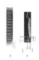
- FIG. 2 (a) shows an example of a barcode viewed from above where the black bar constituting the dark part is black and the ground color constituting the bright part is gray.
- FIG. 2B shows an analog read signal when the barcode shown in FIG. 2A is arranged on a white arrangement surface which is a barcode arrangement object and is read by a normal barcode reader. The waveform is shown.
- a normal barcode reader recognizes that the highest potential A is a potential corresponding to the lightness of the light portion of the barcode, and recognizes that the lowest potential B is a potential corresponding to the lightness of the dark portion of the barcode, An intermediate potential between these two potentials A and B is set as a threshold value.
- the potential of the analog read signal is compared with a threshold value and binarized. Therefore, in order to perform binarization after setting an intermediate potential between the potential A corresponding to white on the arrangement surface in FIG. 2B and the potential B corresponding to black in the dark part of the black bar, a part of the quiet zone is used. It will be recognized as a black bar. Accordingly, since the binarized data does not correspond to the barcode pattern, the barcode cannot be normally decoded.
- FIG. 2 shows the case where the length of the quiet zone of the barcode is shorter than the standard, but the same applies when the length of the quiet zone satisfies the standard, and the barcode is normally decoded. I can't.
- FIG. 2 only the quiet zone before the barcode symbol is shown, but there is also a quiet zone behind the barcode symbol.
- Patent Document 1 discloses an optical information reader capable of decoding even when a bright portion of a printed barcode is gray and the periphery of the barcode is white. However, Patent Document 1 detects an error in which a black region is included in a region to be recognized as a margin (margin corresponding region), reconstructs the array data so as to restore the margin corresponding region, and after the reconstruction It is necessary to perform a complicated process of decoding the array data.
- the present invention provides a barcode reader capable of decoding a barcode by simple processing even when the reflectance around the barcode is higher than the reflectance of the bright portion of the barcode,
- An object is to provide a barcode reading method and a barcode reading program.
- information indicated by the bar code based on position information and polarity information of a plurality of edges included in a read signal indicating the intensity of reflected light from the bar code irradiated with the scan light.
- a barcode reader for reading unnecessary edge position information and polarity information generated by a difference between the intensity of reflected light from a quiet zone of the barcode and the intensity of reflected light from an adjacent portion of the quiet zone is deleted.
- An edge deletion unit and when the edge deletion unit detects two consecutive edges having the same polarity, the edge closer to the end of the scan is regarded as the unnecessary edge, and the position information and polarity information of the unnecessary edge
- a bar code reader is provided which is characterized by deleting.
- information indicated by the barcode based on position information and polarity information of a plurality of edges included in a read signal indicating the intensity of reflected light from the barcode irradiated with the scan light.
- the barcode reading method for reading the unnecessary edge position information and polarity information caused by the difference between the intensity of the reflected light from the quiet zone of the barcode and the intensity of the reflected light from the adjacent portion of the quiet zone is deleted.
- the position information and polarity information of the unnecessary edge are deleted by detecting the position of the unnecessary edge by using the edge closer to the end of the scan as the unnecessary edge when two consecutive edges having the same polarity are detected.
- a barcode reading method is provided which is performed by deleting the polarity information.
- information indicated by the barcode based on position information and polarity information of a plurality of edges included in a read signal indicating the intensity of reflected light from the barcode irradiated with the scan light.
- a bar code reading program for causing a computer to function as a bar code reader for reading a bar code, wherein the bar code reading program causes the computer to reflect the intensity of the reflected light from the quiet zone of the bar code and adjacent to the quiet zone.
- the barcode can be decoded with a simple process.
- FIG. 1 It is a conceptual diagram which shows the structure of a normal barcode reader.
- A shows an example in the case where a black bar constituting a dark part is black and a bar code in which a ground color constituting a bright part is gray is viewed from above.
- B shows the waveform of the analog read signal when the barcode shown in (a) is placed on the white placement surface which is the barcode placement target and is read by a normal barcode reader.
- FIG. 4 is a waveform diagram for explaining a read analog signal waveform of a portion where black bars and white bars of a bar code are alternately continued according to an embodiment of the present invention and a bar code reading method for reading a bar code therefrom.
- FIG. 4 is a waveform diagram for explaining a barcode quiet zone and a signal waveform of a neighboring portion thereof and a barcode reading method for reading the barcode therefrom according to an embodiment of the present invention. It is a flowchart which shows a part of process shown in FIG. 5, and the process added to it.
- the above-described problem is solved by performing the following preprocessing after projecting light on a barcode and A / D converting received light data.
- the white bar starts from the change start point or the black bar starts based on the data indicating whether the change start point is the “rise” change start point or the “fall” change start point To decide. Further, the midpoint of the “rise” change start point and the subsequent change end point is obtained, and the midpoint of the “fall” change start point and the subsequent change end point is obtained. The bar width is determined based on the distance between the midpoint corresponding to the “rise” change start point and the midpoint corresponding to the “fall” change start point.
- FIG. 3 is a conceptual diagram of the barcode reader according to the present embodiment.
- the projection LED 101, barcode 103, light receiving lens 105, CCD 107, analog amplifier 109, and GPIO 113 shown in FIG. 3 are the projection LED 901, barcode 903, light reception lens 905, CCD 907, and analog amplifier 909 shown in FIG. 1, respectively. Since it is the same as that of GPIO 913, overlapping description thereof will be omitted.
- the bar code reader according to the present embodiment is different from the normal bar code reader in the following points. That is, an A / D conversion unit 121, a memory 123, and a preprocessing unit 125 are added between the analog amplifier 109 and the decoding unit 111. Further, the decoding unit 111 is not the same as the decoding unit 911.
- the A / D converter 121 converts the read analog signal output from the CCD sensor 107 and amplified by the analog amplifier 109 into input data that is a digital signal. More specifically, the A / D converter (Analog-to-Digital Converter) 121 converts the read analog signal input from the analog amplifier 109 into a digital signal having a predetermined sampling rate and a predetermined number of bits. Each sample of the signal is each input data.
- the memory 123 stores each input data A / D converted by the A / D converter 121 for one scan.
- the preprocessing unit 125 performs predetermined processing (described later) to generate data indicating whether each bar is a black bar or each white bar, and data indicating the width of each bar. These data are supplied to the decoding unit 111.
- the CPU 115 includes an A / D conversion unit 121, a memory 123, a preprocessing unit 125, and a decoding unit 111.
- Each of the A / D conversion unit 121, the preprocessing unit 125, and the decoding unit 111 may be hardware built in the CPU 115, or may be software by the CPU 115 reading and executing a program. Further, a mixture of these may be used.
- a / D conversion unit 121 may be arranged outside the CPU instead of inside the CPU 115 so that the CPU 115 controls them. Good.
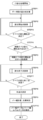
- FIG. 5 is a flowchart showing a flow of processing performed by the preprocessing unit 125
- FIG. 6 is a flowchart showing a detailed flow of the change start point search processing of the flow of FIG. 5
- FIG. 7 is a flowchart of FIG. It is a flowchart which shows the detailed flow of the change end point search process of a flow.
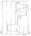
- FIG. 8 is a waveform diagram showing a read analog signal waveform or the like of a portion where black bars and white bars of a bar code are alternately continued
- FIG. 9 is a read analog signal waveform or the like of a quiet zone of the bar code and its adjacent portion.
- FIG. 8 is a waveform diagram showing a read analog signal waveform or the like of a portion where black bars and white bars of a bar code are alternately continued
- FIG. 9 is a read analog signal waveform or the like of a quiet zone of the bar code and its adjacent portion.
- the input data for one scan obtained by projecting light onto the bar code, receiving the reflected light (scanning the bar code), and A / D converting the analog read signal indicating the received light intensity is the input data area of the memory 123 When stored in 123-1 (FIG. 4), the following processing is performed.
- a difference between data adjacent to each other (that is, between sample data adjacent to each other) is calculated (STEP 1). More specifically, for all input data for one scan stored in the input data area 123-1 of the memory 123, the difference from the adjacent input data is calculated. That is, difference data that is the difference between the input data stored at address n included in the input data area 123-1 of the memory 123 and the input data stored at address (n + 1) is calculated, and the difference data is calculated. Are stored at address n included in the difference data area 123-2 of the memory 123.
- (2-1) Search for a change start point (STEP 201). More specifically, the absolute value of the difference data between the self-input data and the previous input data (difference data stored in the differential data area 123-2 of the memory 123 corresponding to the previous input data) Is less than a predetermined value, and the absolute value of the difference between the input data and the input data immediately after (the difference data stored in the difference data area 123-2 of the memory 123 corresponding to the input data) If the value is equal to or greater than a predetermined value, a certain address of the input data is set as a change start point memory address corresponding to the change start point.
- Code data indicating whether the change start point is the “rise” change start point or the “fall” change start point is stored in the code data area 123-4 of the memory 123.
- the change start stored in the change start point area of the memory 123 is code data indicating whether the change start point is a “rise” change start point or a “fall” change start point. It is stored in the code data area 123-4 so as to be associated with the memory address (STEP 206).
- the absolute value of the difference data (difference data stored in the difference data area 123-2 corresponding to the immediately preceding input data) between the input data and the immediately preceding input data is not less than a predetermined value.
- the absolute value of the difference between the input data and the input data immediately after (the difference data stored in the difference data area 123-2 corresponding to the input data) is less than a predetermined value.
- the memory address having the input data is set as the change end point memory address corresponding to the change end point (STEP 601).
- the predetermined value as the threshold when searching for the change end point may be the same as the predetermined value when searching for the change start point, or may be determined separately.
- the change end point first found from the position of each change start point is the change end point corresponding to the change start point. Therefore, it is only necessary to find one change end point for each change start point, and therefore it is not necessary to perform a process for deleting some change end points later.
- the change end point memory address is stored in the change end point memory address area 123-5 in association with the corresponding change start point memory address (STEP 602).
- a midpoint between the change start point and the change end point is determined (STEP 8). Specifically, the memory address closest to the average value of the change start point memory address corresponding to the change start point and the subsequent (end corresponding) change end point memory address is determined as the midpoint memory address corresponding to the midpoint. To do. Then, the midpoint memory address is stored in the midpoint memory address area 123-6.
- the change end point and midpoint corresponding to the deleted change start point cannot be obtained.
- the change start point, the change end point, and the midpoint can be treated as a set of points corresponding to one edge, and thus deleting the change start point is the same as not generating the corresponding edge. It is. Even if the change end point and the midpoint are obtained without deleting the change start point, and then the change start point, the change end point and the midpoint are deleted, the same result can be obtained. In this case, it can be said that this deletion is an edge deletion.
- the edge is a general term for a rising edge and a falling edge.
- the bar width In the calculation of the bar width, a numerical value obtained by multiplying a difference between two midpoint memory addresses respectively corresponding to two midpoints adjacent to each other by a predetermined coefficient is used as the bar width.
- the input data indicating the received light intensity is A / D converted at a predetermined interval and then stored in consecutive memory addresses in the input data area 123-1 of the memory 123. Therefore, as described above, the bar width can be calculated based on the difference between two midpoint memory addresses respectively corresponding to two midpoints adjacent to each other.
- the section that starts from the change start point of “rise”, passes through the change end point and the change start point of “fall”, and ends at the change end point is determined to be a white bar section.
- the section that starts from the “falling” change start point passes through the change end point and the “rise” change start point, and ends at the change end point is determined to be a black bar section. Therefore, the bar binary level data region 123-7 is associated with the bar binary level data indicating whether each section corresponds to the white bar or the black bar, and the bar width data. And stored in the bar width data area 123-8. If the bar binary level data and the bar width data are stored in a common address in the appearance order of the bars in these areas, the addresses can be used for decoding. Further, the appearance order of bars may be stored as data associated with the bar binary level data and the bar width data. The bar binary level data and the bar width data may be further associated with a change start point memory address. Also, code data may be used instead of the bar binary level data.
- the decoding unit 111 Based on the bar binary level data stored in the bar binary level data area 123-7 of the memory 123 and the bar width data stored in the bar width data area 123-8, the decoding unit 111 Decode the code.
- the search for the change end point is performed after the search for the change start point.
- the search for the change start point may be performed after the search for the change end point.
- it may be determined one by one from the first data, whether it is a change start point or a change end point. Even in these cases, the last edge of the edges corresponding to two consecutive “rising edges” and the first edge of the edges corresponding to two consecutive “falling edges” are deleted. To do.
- FIG. 8 shows a waveform of a read analog signal corresponding to a portion where black bars and white bars of a bar code are alternately continued.
- the waveform of the read analog signal is indicated by a continuous line, and the sample points obtained by A / D conversion are indicated by small diamonds on the continuous line.
- a white circle indicates a rising change start point
- a black circle indicates a falling change start point
- a black triangle indicates a change end point corresponding to any of them.
- the memory addresses close to the average value of the change start point memory address corresponding to the position of the A point and the change end point memory address corresponding to the position of the B point are the points A and B.
- the midpoint memory address corresponding to the midpoint 1 position is the memory address close to the average value of the change start point memory address corresponding to the position of the C point and the change end point memory address corresponding to the position of the D point.
- the memory address close to the average value of the change start point memory address corresponding to the position of the C point and the change end point memory address corresponding to the position of the D point is the position of the middle point 2 between the C point and the D point. Is the midpoint memory address corresponding to.
- the difference memory address which is a difference from the midpoint memory address corresponding to the midpoint 1 and the midpoint memory address corresponding to the midpoint 2
- the distance between these midpoints is calculated as the bar width.
- FIG. 9 shows the waveform of the read analog signal corresponding to the quiet zone of the bar code and its adjacent part.
- the dark part of the barcode printed on the barcode is black
- the bright part of the barcode is gray
- the periphery of the barcode is white.
- the quiet zone and the white bar are bright and gray.
- it is a waveform of a read analog signal in the case of reading the quiet zone and reading the bar code symbol after reading the white color of the adjacent part preceding the bar code in the vicinity of the scan start point.
- the original waveform is indicated by a continuous line
- the sample points obtained by A / D conversion are indicated by small diamonds on the continuous line.
- a white circle indicates a rising change start point
- a black circle indicates a falling change start point
- a black triangle indicates a change end point corresponding to any of them.
- the point E is determined as the rising change start point
- the point F is determined as the change end point
- the point G is determined as the falling change start point
- the point H is determined as the change end point.
- the midpoint 3 corresponding to the E point and the F point is set as one midpoint
- the midpoint 4 corresponding to the G point and the H point is set as another midpoint.
- the point X is detected as the falling change start point, but is deleted in STEP4 and STEP5. Accordingly, along with this, the point Y is not detected as the falling change end point. Further, along with these, the midpoint corresponding to the point X and the point Y is not calculated.
- the bright portion of the barcode is gray and the adjacent portion of the barcode is white
- the falling change start point X and the falling change start point G are continuous, the previous “falling” change start point X is deleted, and the subsequent “falling” change start point G is deleted.
- the point is kept as it is. That is, since the falling change start point X and the falling change start point G are continuous, the previous “falling” change start point X is not caused by the barcode pattern. It is determined that there is no change, and the subsequent “falling” change start point G is determined to be caused by the barcode pattern.
- the area from the point E to the point H is recognized as one white bar, and the distance between the midpoint 3 and the midpoint 4 is calculated as the bar width corresponding to the white bar.
- FIG. 9 partially overlaps with the above description, but the bright portion of the barcode printed on the barcode is gray, the adjacent portion of the barcode level is white, and the outside of the adjacent portion.
- the waveform etc. when a black part exists in are shown. That is, in FIG. 9, point E corresponds to the black portion further outside the white portion around the barcode, and the range from point F to point X corresponds to the white portion around the barcode. Is.
- the level of the scan start point becomes equal to the level of the F point and the X point, so the scan start point and the first falling edge There is no rising change start point between the X points, which are the change points, and thus this setting is performed.
- FIG. 10 shows a part of the flowchart in which the above (A) is represented by STEPs 11 and 12 and the above (B) is represented by STEPs 13 and 14.
- FIG. 9 shows an example in which the bright portion of the barcode is gray and the adjacent portion of the barcode is white, after scanning the white portion of the adjacent portion of the barcode in the vicinity of the scan start point.
- An example of scanning a barcode is shown.
- the white color around the barcode is scanned. Therefore, in the vicinity of the scan end point, the rising from the last dark part of the barcode to the bright part and the rising from the last bright part of the barcode to the white part around the barcode are continued twice. As a process to cope with this, the latter “rise” change start point data is deleted, and the former “rise” change start point data is left.
- the edge closer to the end along the barcode scanning direction is deleted as an unnecessary edge. That is, the edge close to the end of the scan is deleted as an unnecessary edge.
- the side close to the scanning end is the side near the scanning start end if it is the scanning start end, and the side near the scanning end if it is the scan end end. is there.
- the present invention is not limited thereto.
- the present invention can be applied to a case where similar characteristics are obtained with respect to light having a predetermined wavelength, for example.
- the present invention can also be applied to the above example and when the brightness is reversed.
- the above barcode reader can be realized by hardware, software, or a combination thereof.
- the barcode reading method performed by the above barcode reader can also be realized by hardware, software, or a combination thereof.
- “realized by software” means realized by a computer reading and executing a program.
- the program can be any type of non-transitory computer readable medium. readable medium) and can be supplied to a computer.
- Non-transitory computer readable media include various types of tangible storage media. Examples of non-transitory computer-readable media include magnetic recording media (for example, flexible disks, magnetic tapes, hard disk drives), magneto-optical recording media (for example, magneto-optical disks), CD-ROMs (Read Only Memory), CD-ROMs. R, CD-R / W, semiconductor memory (for example, mask ROM, PROM (Programmable ROM), EPROM (Erasable PROM), flash ROM, RAM (random access memory)).
- the program may also be supplied to the computer by various types of transitory computer readable media. Examples of transitory computer readable media include electrical signals, optical signals, and electromagnetic waves.
- the temporary computer-readable medium can supply the program to the computer via a wired communication path such as an electric wire and an optical fiber, or a wireless communication path.
- a bar code reader that reads information indicated by the bar code based on position information and polarity information of a plurality of edges included in a read signal indicating the intensity of reflected light from the bar code irradiated with scan light.
- An edge deleting unit that deletes position information and polarity information of unnecessary edges caused by a difference between the intensity of reflected light from the quiet zone of the barcode and the intensity of reflected light from an adjacent portion of the quiet zone; The edge deletion unit, when detecting two consecutive edges having the same polarity, deletes the position information and polarity information of the unnecessary edge by using the edge closer to the end of the scan as the unnecessary edge. Bar code reader.
- Appendix 3 The barcode reader according to Appendix 1 or 2, If there is no other edge between the scan end and the first edge having a certain polarity when viewed from the scan end, the scan end is defined as an edge having a polarity opposite to the certain polarity.
- a bar code reader further comprising a decoder for decoding information indicated by the bar code based on the width data of each bar and the binary level data of each bar.
- Appendix 6 The barcode reader according to any one of appendices 1 to 5, A plurality of edges included in one scan based on difference data for one scan corresponding to input data for one scan representing the read signal, each representing difference between input data adjacent to each other.
- a bar code reading method comprising: decoding information indicated by the bar code based on the width data of each bar and the binary level data of each bar.
- the bar code reading program includes a computer, Including functioning as an edge deletion unit that deletes position information and polarity information of unnecessary edges caused by a difference between the intensity of reflected light from the quiet zone of the barcode and the intensity of reflected light from an adjacent portion of the quiet zone. , The edge deletion unit, when detecting two consecutive edges having the same polarity, deletes the position information and polarity information of the unnecessary edge by using the edge closer to the end of the scan as the unnecessary edge.
- a barcode reading program includes a computer, Including functioning as an edge deletion unit that deletes position information and polarity information of unnecessary edges caused by a difference between the intensity of reflected light from the quiet zone of the barcode and the intensity of reflected light from an adjacent portion of the quiet zone.
- the barcode reading program according to supplementary note 13, comprising: A bar code reading program which further causes the computer to function so as to use the polarity of the change start point corresponding to the edge as the polarity of the edge.
- the barcode reading program according to supplementary note 13 or 14, If there is no other edge between the scan end and the first edge having a certain polarity when viewed from the scan end, the scan end is defined as an edge having a polarity opposite to the certain polarity. As described above, the bar code reading program further causes the computer to function.
- the barcode reading program according to any one of supplementary notes 13 to 15, The width information of each bar is obtained based on the position information of a plurality of edges remaining after the position information and polarity information of unnecessary edges are deleted by the edge deletion unit, and the position information and polarity of unnecessary edges are obtained by the edge deletion unit.
- a bar code reading program for further causing the computer to function to obtain binary level data of each bar based on polarity information of the plurality of edges remaining after information is deleted.
- the barcode reading program according to supplementary note 16, A bar code reading program which further causes the computer to function to decode information indicated by the bar code based on the width data of each bar and the binary level data of each bar.
- the present invention can be used to read barcodes.
Landscapes
- Physics & Mathematics (AREA)
- Engineering & Computer Science (AREA)
- Electromagnetism (AREA)
- Artificial Intelligence (AREA)
- Toxicology (AREA)
- General Health & Medical Sciences (AREA)
- Health & Medical Sciences (AREA)
- Computer Vision & Pattern Recognition (AREA)
- General Physics & Mathematics (AREA)
- Theoretical Computer Science (AREA)
- Quality & Reliability (AREA)
- Character Input (AREA)
- Cash Registers Or Receiving Machines (AREA)
- Printers Characterized By Their Purpose (AREA)
- Telephone Function (AREA)
Abstract
Description
103 バーコード
105 受光レンズ
107 CCD
109 アナログ増幅器
111 デコード部
113 GPIO
115 CPU
121 A/D変換部
123 メモリ
125 前処理部
(6)変化開始点と変化終了点間との間の中点を決定する(STEP8)。具体的には、変化開始点に対応する変化開始点メモリ番地とそれに続く(それに対応する)変化終了点メモリ番地との平均値に最も近いメモリ番地を、中点に対応する中点メモリ番地とする。そして、中点メモリ番地を中点メモリ番地用領域123-6に格納する。
readable medium)を用いて格納され、コンピュータに供給することができる。非一時的なコンピュータ可読媒体は、様々なタイプの実体のある記録媒体(tangible storage medium)を含む。非一時的なコンピュータ可読媒体の例は、磁気記録媒体(例えば、フレキシブルディスク、磁気テープ、ハードディスクドライブ)、光磁気記録媒体(例えば、光磁気ディスク)、CD-ROM(Read Only Memory)、CD-R、CD-R/W、半導体メモリ(例えば、マスクROM、PROM(Programmable ROM)、EPROM(Erasable PROM)、フラッシュROM、RAM(random access memory))を含む。また、プログラムは、様々なタイプの一時的なコンピュータ可読媒体(transitory computer readable medium)によってコンピュータに供給されてもよい。一時的なコンピュータ可読媒体の例は、電気信号、光信号、及び電磁波を含む。一時的なコンピュータ可読媒体は、電線及び光ファイバ等の有線通信路、又は無線通信路を介して、プログラムをコンピュータに供給できる。
前記バーコードのクワイエットゾーンからの反射光の強度と前記クワイエットゾーンの隣接部からの反射光の強度との差により生ずる不要エッジの位置情報と極性情報を削除するエッジ削除部を備え、
前記エッジ削除部は、連続している2つの同一極性のエッジを検出したら、スキャンの端部に近い側のエッジを前記不要エッジとして、該不要エッジの位置情報と極性情報を削除することを特徴とするバーコードリーダ。
前記エッジの極性として、そのエッジに対応する変化開始点の極性を利用することを特徴とするバーコードリーダ。
スキャン端部と前記スキャン端部から見て最初の或る極性のエッジとの間に、他のエッジが無い場合には、前記スキャン端部を前記或る極性と反対の極性を有するエッジとすることを特徴とするバーコードリーダ。
前記エッジ削除部により不要エッジの位置情報と極性情報が削除された後に残った複数のエッジの位置情報に基づいて、各バーの幅データを求め、前記エッジ削除部により不要エッジの位置情報と極性情報が削除された後に残った前記複数のエッジの極性情報に基づいて、各バーの二値レベルデータを求めることを特徴とするバーコードリーダ。
前記各バーの幅データと前記各バーの二値レベルデータに基づいて、前記バーコードが示す情報をデコードするデコーダを更に備えることを特徴とするバーコードリーダ。
前記読取り信号を表す1スキャン分の入力データにそれぞれ対応する1スキャン分の差分データであって、相互に隣接する入力データ間の差分を表す差分データに基づいて、1スキャンに含まれる複数のエッジを検出するエッジ検出部を更に備えることを特徴とするバーコードリーダ。
前記バーコードのクワイエットゾーンからの反射光の強度と前記クワイエットゾーンの隣接部からの反射光の強度との差により生ずる不要エッジの位置情報と極性情報を削除し、
前記不要エッジの位置情報と極性情報の削除は、連続している2つの同一極性のエッジを検出したら、スキャンの端部に近い側のエッジを前記不要エッジとして、該不要エッジの位置情報と極性情報を削除することにより行われることを特徴とするバーコード読取り方法。
前記エッジの極性として、そのエッジに対応する変化開始点の極性を利用することを特徴とするバーコード読取り方法。
スキャン端部と前記スキャン端部から見て最初の或る極性のエッジとの間に、他のエッジが無い場合には、前記スキャン端部を前記或る極性と反対の極性を有するエッジとすることを更に有することを特徴とするバーコード読取り方法。
前記不要エッジの位置情報と極性情報の削除により不要エッジの位置情報と極性情報が削除された後に残った複数のエッジの位置情報に基づいて、各バーの幅データを求め、前記不要エッジの位置情報と極性情報の削除により不要エッジの位置情報と極性情報が削除された後に残った前記複数のエッジの極性情報に基づいて、各バーの二値レベルデータを求めることを特徴とするバーコード読取り方法。
前記各バーの幅データと前記各バーの二値レベルデータに基づいて、前記バーコードが示す情報をデコードすることを特徴とするバーコード読取り方法。
前記読取り信号を表す1スキャン分の入力データにそれぞれ対応する1スキャン分の差分データであって、相互に隣接する入力データ間の差分を表す差分データに基づいて、1スキャンに含まれる複数のエッジを検出することを特徴とするバーコード読取り方法。
前記バーコード読取り用プログラムは、コンピュータを、
前記バーコードのクワイエットゾーンからの反射光の強度と前記クワイエットゾーンの隣接部からの反射光の強度との差により生ずる不要エッジの位置情報と極性情報を削除するエッジ削除部として機能させることを含み、
前記エッジ削除部は、連続している2つの同一極性のエッジを検出したら、スキャンの端部に近い側のエッジを前記不要エッジとして、該不要エッジの位置情報と極性情報を削除することを特徴とするバーコード読み取り用プログラム。
前記エッジの極性として、そのエッジに対応する変化開始点の極性を利用するように前記コンピュータを更に機能させることを特徴とするバーコード読取り用プログラム。
スキャン端部と前記スキャン端部から見て最初の或る極性のエッジとの間に、他のエッジが無い場合には、前記スキャン端部を前記或る極性と反対の極性を有するエッジとするように前記コンピュータを更に機能させることを特徴とするバーコード読取り用プログラム。
前記エッジ削除部により不要エッジの位置情報と極性情報が削除された後に残った複数のエッジの位置情報に基づいて、各バーの幅データを求め、前記エッジ削除部により不要エッジの位置情報と極性情報が削除された後に残った前記複数のエッジの極性情報に基づいて、各バーの二値レベルデータを求めるように前記コンピュータを更に機能させることを特徴とするバーコード読取り用プログラム。
前記各バーの幅データと前記各バーの二値レベルデータに基づいて、前記バーコードが示す情報をデコードするように前記コンピュータを更に機能させることを特徴とするバーコード読取り用プログラム。
前記読取り信号を表す1スキャン分の入力データにそれぞれ対応する1スキャン分の差分データであって、相互に隣接する入力データ間の差分を表す差分データに基づいて、1スキャンに含まれる複数のエッジを検出するように前記コンピュータを更に機能させることを特徴とするバーコード読取り用プログラム。
Claims (8)
- スキャン光が照射されたバーコードからの反射光の強度を示す読取り信号に含まれる複数のエッジの位置情報と極性情報に基づいて前記バーコードが示す情報を読み取るバーコードリーダであって、
前記バーコードのクワイエットゾーンからの反射光の強度と前記クワイエットゾーンの隣接部からの反射光の強度との差により生ずる不要エッジの位置情報と極性情報を削除するエッジ削除部を備え、
前記エッジ削除部は、連続している2つの同一極性のエッジを検出したら、スキャンの端部に近い側のエッジを前記不要エッジとして、該不要エッジの位置情報と極性情報を削除することを特徴とするバーコードリーダ。 - 請求項1に記載のバーコードリーダであって、
前記エッジの極性として、そのエッジに対応する変化開始点の極性を利用することを特徴とするバーコードリーダ。 - 請求項1又は2に記載のバーコードリーダであって、
スキャン端部と前記スキャン端部から見て最初の或る極性のエッジとの間に、他のエッジが無い場合には、前記スキャン端部を前記或る極性と反対の極性を有するエッジとすることを特徴とするバーコードリーダ。 - 請求項1乃至3の何れか1に記載のバーコードリーダであって、
前記エッジ削除部により不要エッジの位置情報と極性情報が削除された後に残った複数のエッジの位置情報に基づいて、各バーの幅データを求め、前記エッジ削除部により不要エッジの位置情報と極性情報が削除された後に残った前記複数のエッジの極性情報に基づいて、各バーの二値レベルデータを求めることを特徴とするバーコードリーダ。 - 請求項4に記載のバーコードリーダであって、
前記各バーの幅データと前記各バーの二値レベルデータに基づいて、前記バーコードが示す情報をデコードするデコーダを更に備えることを特徴とするバーコードリーダ。 - 請求項1乃至5の何れか1に記載のバーコードリーダであって、
前記読取り信号を表す1スキャン分の入力データにそれぞれ対応する1スキャン分の差分データであって、相互に隣接する入力データ間の差分を表す差分データに基づいて、1スキャンに含まれる複数のエッジを検出するエッジ検出部を更に備えることを特徴とするバーコードリーダ。 - スキャン光が照射されたバーコードからの反射光の強度を示す読取り信号に含まれる複数のエッジの位置情報と極性情報に基づいて前記バーコードが示す情報を読み取るバーコード読取り方法であって、
前記バーコードのクワイエットゾーンからの反射光の強度と前記クワイエットゾーンの隣接部からの反射光の強度との差により生ずる不要エッジの位置情報と極性情報を削除し、
前記不要エッジの位置情報と極性情報の削除は、連続している2つの同一極性のエッジを検出したら、スキャンの端部に近い側のエッジを前記不要エッジとして、該不要エッジの位置情報と極性情報を削除することにより行われることを特徴とするバーコード読取り方法。 - スキャン光が照射されたバーコードからの反射光の強度を示す読取り信号に含まれる複数のエッジの位置情報と極性情報に基づいて前記バーコードが示す情報を読み取るバーコードリーダとしてコンピュータを機能させるためのバーコード読取り用プログラムであって、
前記バーコード読取り用プログラムは、コンピュータを、
前記バーコードのクワイエットゾーンからの反射光の強度と前記クワイエットゾーンの隣接部からの反射光の強度との差により生ずる不要エッジの位置情報と極性情報を削除するエッジ削除部として機能させることを含み、
前記エッジ削除部は、連続している2つの同一極性のエッジを検出したら、スキャンの端部に近い側のエッジを前記不要エッジとして、該不要エッジの位置情報と極性情報を削除することを特徴とするバーコード読み取り用プログラム。
Priority Applications (2)
| Application Number | Priority Date | Filing Date | Title |
|---|---|---|---|
| US14/427,681 US9336424B2 (en) | 2012-12-12 | 2013-11-18 | Barcode reader, barcode reading method, and barcode reading program |
| CN201380047281.XA CN104704509B (zh) | 2012-12-12 | 2013-11-18 | 条形码读取器、条形码读取方法、以及条形码读取程序 |
Applications Claiming Priority (2)
| Application Number | Priority Date | Filing Date | Title |
|---|---|---|---|
| JP2012-271513 | 2012-12-12 | ||
| JP2012271513A JP5424369B1 (ja) | 2012-12-12 | 2012-12-12 | バーコードリーダ、バーコード読取り方法及びバーコード読取り用プログラム |
Publications (1)
| Publication Number | Publication Date |
|---|---|
| WO2014091880A1 true WO2014091880A1 (ja) | 2014-06-19 |
Family
ID=50287292
Family Applications (1)
| Application Number | Title | Priority Date | Filing Date |
|---|---|---|---|
| PCT/JP2013/081015 Ceased WO2014091880A1 (ja) | 2012-12-12 | 2013-11-18 | バーコードリーダ、バーコード読取り方法及びバーコード読取り用プログラム |
Country Status (5)
| Country | Link |
|---|---|
| US (1) | US9336424B2 (ja) |
| JP (1) | JP5424369B1 (ja) |
| CN (1) | CN104704509B (ja) |
| MY (1) | MY158868A (ja) |
| WO (1) | WO2014091880A1 (ja) |
Families Citing this family (2)
| Publication number | Priority date | Publication date | Assignee | Title |
|---|---|---|---|---|
| CN111830780B (zh) * | 2020-06-30 | 2023-11-03 | 华虹半导体(无锡)有限公司 | 光罩和光罩信息读取方法 |
| EP4312150B1 (de) * | 2022-07-25 | 2024-07-10 | Sick Ag | Lesen eines optischen codes |
Citations (1)
| Publication number | Priority date | Publication date | Assignee | Title |
|---|---|---|---|---|
| JP2008140255A (ja) * | 2006-12-04 | 2008-06-19 | Olympus Corp | バーコード読取装置およびバーコード読取方法 |
Family Cites Families (11)
| Publication number | Priority date | Publication date | Assignee | Title |
|---|---|---|---|---|
| US4125765A (en) * | 1977-06-27 | 1978-11-14 | International Business Machines Corporation | Label find method and circuit |
| JP2853933B2 (ja) | 1992-04-03 | 1999-02-03 | 日本電気精器株式会社 | 記録票読取装置の信号処理方法 |
| JP3475529B2 (ja) | 1994-11-25 | 2003-12-08 | 株式会社デンソー | 光学情報読み取り装置の信号処理装置 |
| US6371373B1 (en) * | 1999-05-25 | 2002-04-16 | Matsushita Electric Industrial Co., Ltd. | Method for reading a two-dimensional barcode |
| JP2001014421A (ja) * | 1999-06-28 | 2001-01-19 | Matsushita Electric Ind Co Ltd | バーコード読み取り装置 |
| US6739513B1 (en) * | 2000-09-05 | 2004-05-25 | Rjs Systems International | Box detector in barcode environment |
| KR100667778B1 (ko) | 2004-11-20 | 2007-01-11 | 삼성전자주식회사 | 바코드 판독 방법 및 장치 |
| US8024691B2 (en) * | 2006-09-28 | 2011-09-20 | Mcgill University | Automata unit, a tool for designing checker circuitry and a method of manufacturing hardware circuitry incorporating checker circuitry |
| JP5035042B2 (ja) | 2007-08-29 | 2012-09-26 | 株式会社デンソーウェーブ | 光学的情報読取装置 |
| WO2011027532A1 (ja) * | 2009-09-04 | 2011-03-10 | 株式会社アルバック | 太陽電池モジュールの製造方法及び太陽電池モジュールの製造装置 |
| JP5224398B2 (ja) | 2009-11-11 | 2013-07-03 | Necインフロンティア株式会社 | バーコードリーダおよびラベル貼付システム |
-
2012
- 2012-12-12 JP JP2012271513A patent/JP5424369B1/ja active Active
-
2013
- 2013-11-18 MY MYPI2015700737A patent/MY158868A/en unknown
- 2013-11-18 CN CN201380047281.XA patent/CN104704509B/zh active Active
- 2013-11-18 WO PCT/JP2013/081015 patent/WO2014091880A1/ja not_active Ceased
- 2013-11-18 US US14/427,681 patent/US9336424B2/en active Active
Patent Citations (1)
| Publication number | Priority date | Publication date | Assignee | Title |
|---|---|---|---|---|
| JP2008140255A (ja) * | 2006-12-04 | 2008-06-19 | Olympus Corp | バーコード読取装置およびバーコード読取方法 |
Also Published As
| Publication number | Publication date |
|---|---|
| CN104704509B (zh) | 2016-07-06 |
| MY158868A (en) | 2016-11-16 |
| CN104704509A (zh) | 2015-06-10 |
| JP5424369B1 (ja) | 2014-02-26 |
| US9336424B2 (en) | 2016-05-10 |
| JP2014115953A (ja) | 2014-06-26 |
| US20150278568A1 (en) | 2015-10-01 |
Similar Documents
| Publication | Publication Date | Title |
|---|---|---|
| JP2738098B2 (ja) | 光走査装置 | |
| CN102622569B (zh) | 具有边缘检测增强的条码读取器 | |
| US7337970B2 (en) | Barcode scanner decoding | |
| CN101874250B (zh) | 增强型虚拟扫描线处理 | |
| JP2000507727A (ja) | 高速画像捕捉システムおよび方法 | |
| EP1836646B1 (en) | Bar code scanner decoding | |
| KR100920764B1 (ko) | 고밀도의 광학 심볼을 2단계로 해독하기 위한 장치 및 방법 | |
| JP5424369B1 (ja) | バーコードリーダ、バーコード読取り方法及びバーコード読取り用プログラム | |
| US7506816B2 (en) | System and method for determining a threshold for edge detection based on an undifferentiated equalized scan line signal | |
| US9262665B2 (en) | Decoding method and decoding processing device | |
| JP4188104B2 (ja) | バーコード読取装置 | |
| JP5035042B2 (ja) | 光学的情報読取装置 | |
| JP5896488B2 (ja) | バーコード読取装置、バーコード読取方法及びバーコード読取プログラム | |
| JP6083829B2 (ja) | バーコード読取装置、バーコード読取方法及びバーコード読取プログラム | |
| JP5264956B2 (ja) | 2次元コード読取装置及びその方法 | |
| JP5515012B2 (ja) | バーコード情報読取方法及びバーコード情報読取装置 | |
| JP4728297B2 (ja) | 2次元コード読取装置及びその方法 | |
| US7093763B1 (en) | Laser scanner having analog digitizer with increased noise immunity | |
| JP5349504B2 (ja) | 光学的情報読取装置及び光学的情報読取方法 | |
| CN103577823B (zh) | 对条形码进行二值化方法及装置 | |
| JP2007034546A (ja) | 光学読取装置 | |
| JP5453594B2 (ja) | シンボル情報読取装置及びシンボル情報読取方法 | |
| JP2012009058A (ja) | データコード読取装置及びその方法 | |
| JP4107237B2 (ja) | 光学的情報読取装置の境界位置特定方法 | |
| JP2010033490A (ja) | バーコード読取装置及びバーコード読取方法 |
Legal Events
| Date | Code | Title | Description |
|---|---|---|---|
| 121 | Ep: the epo has been informed by wipo that ep was designated in this application |
Ref document number: 13863176 Country of ref document: EP Kind code of ref document: A1 |
|
| WWE | Wipo information: entry into national phase |
Ref document number: 14427681 Country of ref document: US |
|
| WWE | Wipo information: entry into national phase |
Ref document number: IDP00201501497 Country of ref document: ID |
|
| NENP | Non-entry into the national phase |
Ref country code: DE |
|
| 122 | Ep: pct application non-entry in european phase |
Ref document number: 13863176 Country of ref document: EP Kind code of ref document: A1 |