WO2014091837A1 - 3次元モデル生成装置、3次元モデル生成方法及び3次元モデル生成プログラム - Google Patents
3次元モデル生成装置、3次元モデル生成方法及び3次元モデル生成プログラム Download PDFInfo
- Publication number
- WO2014091837A1 WO2014091837A1 PCT/JP2013/079846 JP2013079846W WO2014091837A1 WO 2014091837 A1 WO2014091837 A1 WO 2014091837A1 JP 2013079846 W JP2013079846 W JP 2013079846W WO 2014091837 A1 WO2014091837 A1 WO 2014091837A1
- Authority
- WO
- WIPO (PCT)
- Prior art keywords
- data
- dimensional
- graph
- point cloud
- cad data
- Prior art date
Links
Images


Classifications
-
- G—PHYSICS
- G06—COMPUTING; CALCULATING OR COUNTING
- G06T—IMAGE DATA PROCESSING OR GENERATION, IN GENERAL
- G06T7/00—Image analysis
- G06T7/30—Determination of transform parameters for the alignment of images, i.e. image registration
- G06T7/33—Determination of transform parameters for the alignment of images, i.e. image registration using feature-based methods
-
- G—PHYSICS
- G06—COMPUTING; CALCULATING OR COUNTING
- G06F—ELECTRIC DIGITAL DATA PROCESSING
- G06F30/00—Computer-aided design [CAD]
-
- G—PHYSICS
- G06—COMPUTING; CALCULATING OR COUNTING
- G06V—IMAGE OR VIDEO RECOGNITION OR UNDERSTANDING
- G06V10/00—Arrangements for image or video recognition or understanding
- G06V10/40—Extraction of image or video features
- G06V10/42—Global feature extraction by analysis of the whole pattern, e.g. using frequency domain transformations or autocorrelation
- G06V10/422—Global feature extraction by analysis of the whole pattern, e.g. using frequency domain transformations or autocorrelation for representing the structure of the pattern or shape of an object therefor
- G06V10/426—Graphical representations
-
- G—PHYSICS
- G06—COMPUTING; CALCULATING OR COUNTING
- G06V—IMAGE OR VIDEO RECOGNITION OR UNDERSTANDING
- G06V20/00—Scenes; Scene-specific elements
- G06V20/60—Type of objects
- G06V20/64—Three-dimensional objects
- G06V20/653—Three-dimensional objects by matching three-dimensional models, e.g. conformal mapping of Riemann surfaces
-
- G—PHYSICS
- G06—COMPUTING; CALCULATING OR COUNTING
- G06T—IMAGE DATA PROCESSING OR GENERATION, IN GENERAL
- G06T2207/00—Indexing scheme for image analysis or image enhancement
- G06T2207/10—Image acquisition modality
- G06T2207/10028—Range image; Depth image; 3D point clouds
-
- G—PHYSICS
- G06—COMPUTING; CALCULATING OR COUNTING
- G06T—IMAGE DATA PROCESSING OR GENERATION, IN GENERAL
- G06T2207/00—Indexing scheme for image analysis or image enhancement
- G06T2207/20—Special algorithmic details
- G06T2207/20072—Graph-based image processing
Definitions
- the present invention relates to a three-dimensional model generation device, a three-dimensional model generation method, and a three-dimensional model generation program.
- the present invention claims the priority of Japanese Patent Application No. 2012-270817 filed on Dec. 11, 2012. For designated countries where weaving by reference is allowed, the contents described in the application are as follows: Is incorporated into this application by reference.
- Patent Document 1 JP-A-2002-8014
- two sets of image groups obtained by photographing a target object together with a plurality of markers arranged around the target object are input, and feature points of the target object and points representing the three-dimensional coordinates of the markers are input from each image group.
- Generating group data, associating markers between two sets of image groups, and integrating with point cloud data based on the point cloud data of the associated markers to extract the entire shape of the target object Are listed.
- a three-dimensional model of the target object cannot be generated unless the target object is photographed together with a plurality of markers arranged around the target object.
- the present invention provides a three-dimensional model generation apparatus, a three-dimensional model generation method, and a three-dimensional model that can automatically generate a three-dimensional model based on the measurement result of an article without photographing a marker or the like together.
- a 3D model generation apparatus acquires point cloud data acquisition that acquires information indicating the position of a member provided in a 3D space as point cloud data that is a collection of point information.
- a graph for the point group data a CAD data acquisition unit for acquiring three-dimensional CAD data, a segment calculation unit for dividing the point cloud data and the three-dimensional CAD data into a plurality of segments, A first graph that is a graph with segments obtained by dividing point cloud data as nodes, and a graph for the three-dimensional CAD data, and a graph that uses nodes obtained by dividing the three-dimensional CAD data as nodes.
- a graph generation unit that generates the graph, a matching unit that matches the first graph and the second graph, and the matching unit
- a classifying unit that classifies a member that is the basis of the point cloud data into a part in which the three-dimensional CAD data exists and a part in which the three-dimensional CAD data does not exist, and a classification by the classification unit
- a three-dimensional model generation unit that generates a three-dimensional model based on the point cloud data based on the result, and when the three-dimensional CAD data is classified as a base member of the point cloud data
- a three-dimensional model generation unit that generates a three-dimensional model with reference to the three-dimensional CAD data.
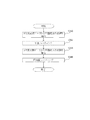
- FIG. 3 is a flowchart showing a process flow of the three-dimensional model generation apparatus 1. It is a flowchart which shows the flow of a matching process. It is a figure explaining a matching process. It is a flowchart which shows the flow of the model creation process based on components. It is a figure which shows an example of the output result of the three-dimensional model production
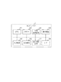
- FIG. 1 is a diagram showing a three-dimensional model generation apparatus 1 according to an embodiment of the present invention.
- the three-dimensional model generation apparatus 1 mainly includes a control unit 11, an output unit 12, an input unit 13, a communication unit 14, and a storage unit 15.
- the three-dimensional model generation apparatus 1 mainly includes a three-dimensional measuring device 20, a member identification model DB (database) 21, a shape fitting DB 22, a display device 25, and a three-dimensional CAD server (not shown) wired or wirelessly. It is connected.
- the control unit 11 performs processing for controlling the entire three-dimensional model generation apparatus 1.
- the internal configuration of the control unit 11 will be described in detail later.
- the output unit 12 outputs a program execution state, a processing result, and the like.
- the input unit 13 inputs a program execution start instruction and a stop instruction from the user.
- the communication unit 14 exchanges data between each unit of the three-dimensional model generation device 1. Further, the communication unit 14 communicates with other devices (for example, a three-dimensional CAD server (not shown)) to exchange data.
- other devices for example, a three-dimensional CAD server (not shown)
- the storage unit 15 temporarily stores the acquired various data and stores the created data.
- the three-dimensional measuring device 20 irradiates each part of a part in a plant or the like with a laser beam and acquires a three-dimensional measurement result.
- the measurement result is subjected to data processing by a processing unit (not shown) or the like, and is output as measurement data 23 to the three-dimensional model generation device 1.
- the measurement data 23 is point cloud data that is an aggregate of point information.
- 3D CAD data 24 is output from the 3D CAD server (not shown) to the 3D model generation apparatus 1.
- the three-dimensional CAD data 24 is three-dimensional CAD data that is three-dimensional design data of parts inside a plant or the like.
- the three-dimensional design data is polygon data.
- the three-dimensional CAD server stores the three-dimensional CAD data 24 of all design parts among the parts to be measured.
- the member identification model DB 21 stores learning data 210.
- the learning data 210 is sample data of parts that are not design parts, such as piping, scaffolding, and auxiliary equipment.
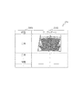
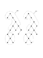
- FIG. 2 is a diagram illustrating a data structure of the learning data 210.
- the learning data 210 has a component storage area 2101 and a sample data storage area 2102.
- the component storage area 2101 and the sample data storage area 2102 are associated with each other.
- the parts storage area 2101 stores the names of parts such as piping, scaffolding, and auxiliary equipment.
- sample data storage area 2102 sample data of a part whose part name is stored in the part storage area 2101 is stored.
- the sample data is three-dimensional point group data.
- FIG. 2 a diagram is shown as sample data, but this is for explanation, and is actually point cloud data capable of recognizing a three-dimensional shape.
- the shape fitting DB 22 stores fitting information 220, which is information necessary for fitting, for parts whose learning data is stored in the member identification model DB 21.
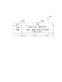
- FIG. 3 is a diagram showing a data structure of the fitting information 220.
- the fitting information 220 includes a component storage area 2201 and a fitting data storage area 2202.
- the component storage area 2201 and the fitting data storage area 2202 are associated with each other.
- the parts storage area 2201 stores the names of parts such as piping, scaffolding, and auxiliary equipment.
- the fitting data storage area 2202 stores information necessary for fitting the parts stored in the parts storage area 2101, that is, information indicating what kind of fitting should be performed (hereinafter referred to as fitting data).
- the fitting data will be described by taking a case where the part is a scaffold as an example.
- the scaffolding is composed of a circular pipe such as an iron pipe and a plate material attached to the circular pipe. Therefore, when “scaffold” is stored in the component storage area 2101, the fitting data storage area 2202 is fitted with the information “a combination of a plane and a circular tube”, that is, fitting point cloud data with a plane and a circular pipe surface. Fitting data indicating that it should be done is stored.
- the display device 25 includes a display device such as a CRT monitor or a liquid crystal monitor.
- the control unit 11 mainly includes a segment calculation unit 111, a graph network calculation unit 112, a graph matching unit 113, a point cloud feature amount calculation unit 114, a part identification unit 115, and a shape fitting. Part 116 and a CAD fitting part 117.
- the segment calculation unit 111 divides each of the measurement data 23 and the three-dimensional CAD data 24 into a plurality of segments such as a plane segment and a curved segment. Data obtained by the segment calculation unit 111 is output to the graph network calculation unit 112. Since the specific process in which the segment calculation unit 111 divides into segments is already known, a description thereof will be omitted.
- the graph network calculation unit 112 for each of the segment of the measurement data 23 and the segment of the three-dimensional CAD data 24 divided by the segment calculation unit 111, specifically, which segment is connected to which segment, Where is the connection position, how many times the connection angle is, etc. are calculated.
- the graph network calculation unit 112 outputs the calculated connection of segments (hereinafter referred to as a graph network) to the graph matching unit 113 as structure information.
- the specific processing performed by the graph network calculation unit 112 is already known, and thus detailed description thereof is omitted.
- the graph matching unit 113 matches the graph network of the measurement data 23 generated by the graph network calculation unit 112 and the graph network of the three-dimensional CAD data 24. Specifically, the graph matching unit 113 compares the graph network of the measurement data 23 and the graph network of the three-dimensional CAD data 24 to obtain the closeness as the network structure. In addition, based on the matching result, the graph matching unit 113 determines whether the component that is the basis of the measurement data 23 is a component that has 3D design data, or the component that is the basis of the measurement data 23 is a component that does not have 3D design data. Classify. The processing performed by the graph matching unit 113 will be described in detail later.
- the point cloud feature quantity calculation unit 114 calculates a feature quantity from the measurement data 23 when the graph matching unit 113 classifies the part that is the basis of the measurement data 23 as a part that does not have 3D design data. For example, the point group feature amount calculation unit 114 calculates the features of the point group such as the variance, size, and centroid distance of a portion of the measurement data 23 in the x direction, y direction, and z direction as the feature amount. Further, the point cloud feature value calculation unit 114 calculates a feature value for the sample data stored in the member identification model DB 21. The feature amount calculated for the sample data is used when creating a learning model. In addition, since the specific process which the point cloud feature-value calculation part 114 performs is already well-known, detailed description is abbreviate
- the component identification unit 115 identifies a component based on the feature amount calculated by the point cloud feature amount calculation unit 114 using a known method such as a support vector machine.
- the component identification unit 115 compares the feature amount of the measurement data 23 calculated by the point cloud feature amount calculation unit 114 with the feature amount of the sample data stored in the member identification model DB 21, and serves as a basis of the measurement data 23. Identifies which part of the parts the sample data is stored in the member identification model DB 21 corresponds to.
- the method used by the component identification unit 115 is not limited to the support vector machine, and any method may be used as long as the identification method performs identification based on the identification rule. Further, since a known method is used for the processing performed by the component identification unit 115, detailed description thereof is omitted.
- the shape fitting unit 116 fits the measurement data 23 based on the identification result of the component identification unit 115.
- the processing of the shape fitting unit 116 will be described in detail later.
- the CAD fitting unit 117 uses the 3D CAD data 24 to fit the measurement data 23. The processing of the CAD fitting unit 117 will be described in detail later.
- FIG. 4 is a block diagram illustrating an example of a schematic configuration of the three-dimensional model generation apparatus 1.
- a three-dimensional model generation device 1 configured by a computer or the like includes a CPU (Central Processing Unit) 101 that is an arithmetic device, a RAM (Random Access Memory) that is a volatile storage device, and a nonvolatile memory device.
- CPU Central Processing Unit
- RAM Random Access Memory
- a memory 102 composed of a ROM (Read only Memory) that is a storage device, an external storage device 103, a communication device 104 that communicates with an external device, and a user interface such as a keyboard, mouse, or touch panel that accepts input from the user ,
- An output device 106 such as a display, a read / write device 107 such as a CD drive or a DVD drive, and an interface (I / F) 108 for connecting the control unit 11 to other units. That.
- Each functional unit of the control unit 11 is realized, for example, by the CPU 101 reading out a predetermined program stored in the memory 102 to the memory 32 and executing it.
- the predetermined program may be installed in the memory 102 in advance, downloaded from the network via the communication device 104, installed or updated, or installed or updated from the external storage device 103, for example. Alternatively, it may be installed or updated from a CD drive or DVD drive via the read / write device 107.
- the input unit 13 is realized by the input device 105.
- the output unit 12 and the communication unit 14 are realized by the communication device 104 and the I / F 108.
- the storage unit 15 is realized by the memory 102.
- the display device 25 is realized by the output device 106. Note that the output device 106 is not essential as a configuration of the three-dimensional model generation device 1, and may be connected via the I / F 108.
- the above-described configuration of the three-dimensional model generation device 1 is the main configuration for describing the features of the present embodiment, and is not limited to the above configuration.
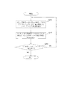
- FIG. 5 is a flowchart showing the overall processing flow of the three-dimensional model generation apparatus 1 in the present embodiment.
- the control unit 11 issues an instruction to the three-dimensional measuring device 20 via the communication unit 14 and performs three-dimensional measurement of the component (step S10).
- the control unit 11 acquires measurement data 23 measured by the three-dimensional measuring device 20 via the communication unit 14 (step S12). Further, the control unit 11 acquires all the three-dimensional CAD data 24 stored in a three-dimensional CAD server (not shown) via the communication unit 14 (step S14).
- the measurement data 23 acquired in step S12 and the three-dimensional CAD data 24 acquired in step S14 are stored in the storage unit 15.
- the segment calculation unit 111 segments the measurement data 23 acquired in step S12, and divides the three-dimensional CAD data 24 acquired in step S14 into element planes (synonymous with segments), so that a plane segment, a curved segment, etc. Divide into a plurality of segments (step S16).
- the graph network calculation unit 112 creates a graph network for each of the measurement data 23 and the three-dimensional CAD data 24 divided into a plurality of segments in step S16 (step S18). Specifically, the graph network calculation unit 112 forms a graph network as information to add the segments of the measurement data 23 to nodes, arcs between connected segments, and the angles to be connected to arcs. In addition, the graph network calculation unit 112 converts the element plane of the three-dimensional CAD data 24 to a node, arcs between connected element planes, and graph network as information to add a connecting angle to the arc.
- the graph matching unit 113 performs matching between the graph network of the measurement data 23 calculated in step S18 and the graph network of the three-dimensional CAD data 24 (step S20).
- step S20 will be specifically described.
- FIG. 6 is a flowchart showing the flow of the matching process (step S20).
- the graph matching unit 113 compares the graph network 230 of the measurement data 23 with the graph network 240 of the three-dimensional CAD data 24, and extracts the most similar nodes and arc aggregates (step S201). As a result of comparison between the graph network 230 of the measurement data 23 and the graph network 240 of the three-dimensional CAD data 24, a plurality of regions where the graph network 230 of the measurement data 23 and the graph network 240 of the three-dimensional CAD data 24 match are extracted. Sometimes. In this case, the graph matching unit 113 extracts the largest aggregate among the plurality of regions, the region with the highest similarity, and the like.
- FIG. 7 is a diagram showing a graph network 230 of measurement data 23 and a graph network 240 of three-dimensional CAD data 24.
- nodes are segments
- arcs indicate connection of segments.
- an area surrounded by a dotted line is extracted as an aggregate in which the graph network 230 of the measurement data 23 and the graph network 240 of the three-dimensional CAD data 24 are similar.
- the graph matching unit 113 is attached to the aggregate extracted from the graph network 240 of the three-dimensional CAD data 24 in step S201 to the aggregate extracted from the graph network 230 of the measurement data 23 in step S201.
- the component names are associated (step S202). If no aggregate is extracted in step S201, the graph matching unit 113 does not associate a name in step S202 and proceeds to the next step.
- the graph matching unit 113 determines whether there is a matching node / arc aggregate (step S203).
- the graph network 230 of the measurement data 23 and the graph network 240 of the three-dimensional CAD data 24 match in a plurality of regions.
- the graph matching unit 113 performs Step S201 again.
- the graph matching unit 113 ends the matching process.
- the closeness as a structure between the graph network 230 of the measurement data 23 and the graph network 240 of the three-dimensional CAD data 24 is required.
- the closeness as a structure can also be calculated by the number of partially matching regions, the area ratio of the regions, and the like.
- the graph matching unit 113 determines whether the component that is the basis of the measurement data 23 is a component that has 3D design data, or the component that is the basis of the measurement data 23 is a component that does not have 3D design data. It is determined whether or not the component that is the basis of the measurement data 23 is a component having three-dimensional design data (step S22). Hereinafter, step S22 will be specifically described.
- the graph matching unit 113 stores the three-dimensional CAD data 24 of the part that is the basis of the point cloud data. Judge that it was input. Then, the graph matching unit 113 classifies the component that is the basis of the measurement data 23 into a component having 3D design data.
- the graph matching unit 113 may be used when there are a plurality of matching areas in the graph network 230 of the measurement data 23 and the graph network 240 of the three-dimensional CAD data 24 or when the graph network 230 of the measurement data 23 and the three-dimensional CAD data 24
- a predetermined threshold for example, 70%
- the graph matching unit 113 performs the three-dimensional CAD data 24 of the component that is the basis of the point cloud data. It is determined that is not entered. Then, the graph matching unit 113 classifies the component that is the basis of the measurement data 23 into a component that does not have 3D design data.
- step S24 When the component that is the basis of the measurement data 23 is classified as a component that does not have the 3D design data (NO in step S22), the control unit 11 determines that the component that is the basis of the measurement data 23 is a 3D model. It is determined whether or not it is a target (step S24). Hereinafter, step S24 will be specifically described.
- the point cloud feature amount calculation unit 114 calculates the feature amount of the sample data stored in the measurement data 23 and the member identification model DB 21.
- the component identification unit 115 compares the feature amount of the measurement data 23 calculated by the point cloud feature amount calculation unit 114 with the feature amount of the sample data stored in the member identification model DB 21, and serves as a basis of the measurement data 23. Identifies which part of the parts the sample data is stored in the member identification model DB 21 corresponds to.
- step S24 NO, the shape fitting unit 116 deletes the measurement data 23 from the storage unit 15 (step S26).
- step S24 YES
- the shape fitting unit 116 performs fitting based on the component identification result to generate a three-dimensional model (step S28).
- step S28 will be specifically described.
- FIG. 8 is a flowchart showing a flow of processing for generating a three-dimensional model by performing fitting based on the component identification result.
- the shape fitting unit 116 acquires, from the shape fitting DB 22, the characteristics of the part that is identified in step S24 and serves as the basis of the measurement data 23. For example, when the component that is the basis of the measurement data 23 is identified as a scaffold in step S 24, the shape fitting unit 116 acquires information “a combination of a plane and a circular tube” from the fitting data storage area 2202. (Step S280).
- the shape fitting unit 116 fits the measurement data 23 based on the information acquired in step S280 (steps S282 to S288).
- the component that is the basis of the three-dimensional model is not limited to a scaffold, and can be formed by joining a plane and a circular tube. Therefore, the shape fitting unit 116 fits a plane and a cylinder separately as described below.
- the shape fitting unit 116 extracts a plane component point group from the measurement data 23 (step S282).
- the shape fitting unit 116 performs plane fitting on the point group extracted in step S282 (step S284).
- the shape fitting unit 116 removes the point component of the plane component from the measurement data 23 (step S286). As a result, only the cylindrical surface component of the measurement data 23 remains, so the shape fitting unit 116 fits the cylindrical surface to the point group from which the plane component point group is removed in step S286 (step S288).
- planar fitting is simpler and more accurate. In general, there are more point groups belonging to a plane than point groups belonging to a curved surface. Therefore, it is desirable to perform curved surface fitting after fitting a plane.
- the CAD fitting unit 117 uses the three-dimensional CAD data 24 to fit the measurement data 23. (Step S30).
- step S30 The process of step S30 will be described using an example.
- the CAD fitting unit 117 performs the fitting of the measurement data 23 so that the matching result obtained by the graph matching unit 113 matches the three-dimensional CAD data 24 and has the same shape as the three-dimensional CAD data 24.
- the shape here is a line, a plane, a curved surface, a circular tube or the like.
- the CAD fitting unit 117 performs fitting on a portion that does not match the three-dimensional CAD data 24.
- the CAD fitting unit 117 uses the three-dimensional CAD data 24 to correct the fitting result generated in step S30 and generate a three-dimensional model (step S32). Specifically, the CAD fitting unit 117 corrects the fitting result using the standard information in the three-dimensional CAD data 24.
- the standard information is information related to the size of the pipe diameter, for example. Thereby, an error between the three-dimensional model based on the measurement result and the design data can be absorbed, and a highly accurate three-dimensional model can be generated.
- step S32 the fitting result is not corrected for portions not related to the standard such as positional deviation. This is because in the present embodiment, it is important to reproduce the measured result. Note that information (hereinafter referred to as difference information) such as the magnitude of positional deviation between the three-dimensional CAD data 24 and the generated three-dimensional model may be held.
- the control unit 11 stores the generated three-dimensional model and difference information in the storage unit 15.
- the output unit 12 outputs the three-dimensional CAD data 24, the three-dimensional model, and the difference information to the display device 25 as necessary.
- FIG. 9 is a display example of the display device 25 when a three-dimensional model and difference information are output. As shown in FIG. 9, the display device 25 displays an image 251 displaying the 3D CAD data 24 and a generated 3D model image 252 based on the 3D CAD data 24 and the 3D model. . Thereby, design data and an actual state can be compared at a glance.
- the display device 25 displays a display area 253 for displaying parts for which the three-dimensional CAD data 24 exists, and a display area 254 for displaying parts for which the three-dimensional CAD data does not exist. Thereby, it can be easily confirmed whether or not the three-dimensional CAD data 24 exists.
- the display device 25 displays, based on the difference information, a display area 255 for displaying that the position of the part in which the three-dimensional CAD data 24 exists is different from the three-dimensional CAD data 24, and the shape of the three-dimensional CAD data 24 and the shape.
- a display area 256 is displayed to indicate that they are different.
- the generated three-dimensional model image 252 may be displayed so that the difference can be recognized.
- portions of the three-dimensional model that are not in the three-dimensional CAD data 24 are displayed in black.
- portions that are different in position and shape from the three-dimensional CAD data 24 are shaded.
- FIG. 9 is an example of display on the display device 25 when the three-dimensional model and the difference information are output, and the display form is not limited to this.
- FIG. 10 is a display example of the display device 25 when a three-dimensional model is output. As shown in FIG. 10, the generated three-dimensional model image 252 is displayed on the display device 25. Thereby, a three-dimensional model can be confirmed.
- a three-dimensional model can be automatically generated from the measurement result.
- the 3D model is generated with reference to the 3D CAD data, so that the 3D model can be generated quickly and with high accuracy.
- a highly accurate three-dimensional model can be generated by correcting a three-dimensional model generated based on three-dimensional CAD data.
- a part is identified with reference to sample data, and a 3D model is generated based on the feature of the part, thereby achieving high accuracy 3 A dimensional model can be generated.
- the measurement data when the three-dimensional model is not generated, the measurement data can be deleted to eliminate noise and increase the processing speed and accuracy.
- this invention is not limited to the above-mentioned Example, Various modifications are included.
- the above-described embodiments have been described in detail for easy understanding of the present invention, and are not necessarily limited to those having all the configurations described. It is also possible to add the configuration of another embodiment to the configuration of one embodiment. Further, it is possible to add, delete, and replace other configurations for a part of the configuration of each embodiment.
- each of the above-described configurations, functions, processing units, processing means, and the like may be realized by hardware by designing a part or all of them with, for example, a modification opportunity.
- Each of the above-described configurations, functions, and the like may be realized by software by interpreting and executing a program that realizes each function by the processor.
- Information such as programs, tables, and files for realizing each function can be stored in a memory, a hard disk, a recording device such as an SSD (Solid State Drive), or a recording medium such as an IC card, an SD card, or a DVD.
- control lines and information lines indicate what is considered necessary for explanation, and not all control lines and information warfare on the product are necessarily shown. In practice, it may be considered that almost all the components are connected to each other.
- 1 three-dimensional model generation apparatus, 11: control unit, 12: output unit, 13: input unit, 14: communication unit, 15: storage unit, 20: three-dimensional measuring instrument, 21: member identification model DB, 22: shape Fitting DB, 23: measurement data, 24: three-dimensional CAD data, 25: display device, 111: segment calculation unit, 112: graph network calculation unit, 113: graph matching unit, 114: point cloud feature value calculation unit, 115: Component identification unit, 116: shape fitting unit, 117: CAD fitting unit, 210: learning data, 220: fitting information
Landscapes
- Engineering & Computer Science (AREA)
- Theoretical Computer Science (AREA)
- Physics & Mathematics (AREA)
- General Physics & Mathematics (AREA)
- Multimedia (AREA)
- Computer Vision & Pattern Recognition (AREA)
- Software Systems (AREA)
- Computer Hardware Design (AREA)
- Evolutionary Computation (AREA)
- Geometry (AREA)
- General Engineering & Computer Science (AREA)
- Processing Or Creating Images (AREA)
- Image Generation (AREA)
Abstract
マーカー等を一緒に撮影することなく、物品の測定結果に基づいて自動的に3次元モデルを生成することができる。 部材の点群データ及び3次元CADデータを取得する。点群データ及び3次元CADデータを複数のセグメントに分割する。点群データを分割したセグメントをノードとした第1のグラフ及び3次元CADデータを分割したセグメントをノードとした第2のグラフを生成する。第1のグラフと第2のグラフとをマッチングする。マッチング結果に基づいて、点群データの基となる部材を3次元CADデータが存在する部品としない部品とに分類する。分類結果に基づいて点群データに基づいた3次元モデルを生成する。点群データの基となる部材の3次元CADデータが存在する場合には、3次元CADデータを参照して3次元モデルを生成する。
Description
本発明は、3次元モデル生成装置、3次元モデル生成方法及び3次元モデル生成プログラムに関するものである。本発明は2012年12月11日に出願された日本国特許の出願番号2012-270817の優先権を主張し、文献の参照による織り込みが認められる指定国については、その出願に記載された内容は参照により本出願に織り込まれる。
本技術分野の背景技術として、特開2002-8014(特許文献1)がある。この公報には、対象物体を、その周囲に配された複数のマーカーと一緒に撮影した2組の画像群を入力し、各画像群から対象物体の特徴点及びマーカーの3次元座標を表す点群データを生成し、2組の画像群間でマーカーの対応付けを行い、対応付けられたマーカーの点群データに基づき点群データと統合して、対象物体の全周形状を抽出することが記載されている。
しかし、上記技術では、対象物体を、その周囲に配された複数のマーカーと一緒に撮影しなければ、対象物体の3次元モデルを生成することはできない。
そこで、本発明は、マーカー等を一緒に撮影することなく、物品の測定結果に基づいて自動的に3次元モデルを生成することができる3次元モデル生成装置、3次元モデル生成方法及び3次元モデル生成プログラムを提供する。
上記課題を解決すべく、本発明に係る3次元モデル生成装置は、三次元空間内に設けられた部材の位置を示す情報を点情報の集合体である点群データとして取得する点群データ取得部と、3次元CADデータを取得するCADデータ取得部と、前記点群データ及び前記3次元CADデータを複数のセグメントに分割するセグメント算出部と、前記点群データについてのグラフであって、前記点群データを分割したセグメントをノードとしたグラフである第1のグラフ、及び前記3次元CADデータについてのグラフであって、前記3次元CADデータを分割したセグメントをノードとしたグラフである第2のグラフを生成するグラフ生成部と、前記第1のグラフと前記第2のグラフとをマッチングするマッチング部と、前記マッチング部によるマッチング結果に基づいて、前記点群データの基となる部材を前記3次元CADデータが存在する部品と、前記3次元CADデータが存在しない部品とに分類する分類部と、前記分類部による分類結果に基づいて前記点群データに基づいた3次元モデルを生成する3次元モデル生成部であって、前記点群データの基となる部材について前記3次元CADデータが存在すると分類された場合には、前記3次元CADデータを参照して3次元モデルを生成する3次元モデル生成部と、を備えることを特徴とする。
本発明によれば、マーカー等を一緒に撮影することなく、物品の測定結果に基づいて自動的に3次元モデルを生成することができる。
以下、実施例を図面を用いて説明する。
[構成の説明]図1は、本発明の一実施形態である3次元モデル生成装置1を示す図である。3次元モデル生成装置1は、主として、制御部11と、出力部12と、入力部13と、通信部14と、記憶部15とを有する。3次元モデル生成装置1には、主として、3次元測定器20と、部材識別モデルDB(データベース)21と、形状フィッティングDB22と、表示装置25と、図示しない3次元CADサーバとが有線又は無線で接続されている。
制御部11は、3次元モデル生成装置1の全体を制御する処理を行う。制御部11の内部の構成については、後に詳述する。
出力部12は、プログラムの実行状態、処理結果等の出力を行う。
入力部13は、ユーザからのプログラム実行開始指示や中止指示等の入力を行う。
通信部14は、3次元モデル生成装置1の各部間のデータ交換を行う。また、通信部14は、他装置(例えば図示しない3次元CADサーバ)と通信してデータ交換を行う。
記憶部15は、取得した各種データを一時的に保存したり、作成したデータを記憶したりする。
3次元測定器20は、プラント等の内部にある部品の各部位にレーザビームを照射し、三次元の測定結果を取得する。測定結果は、図示しない処理部等でデータ処理され、測定データ23として3次元モデル生成装置1に出力される。測定データ23は、点情報の集合体である点群データである。
さらに、3次元モデル生成装置1には、3次元CADデータ24が図示しない3次元CADサーバから出力される。3次元CADデータ24は、プラント等の内部にある部品の3次元設計データである3次元CADデータである。なお、本実施の形態では、3次元設計データはポリゴンデータである。本実施の形態では、3次元CADサーバには、計測対象の部品のうち、全ての設計部品の3次元CADデータ24が記憶されている。
部材識別モデルDB21は、学習データ210を格納する。学習データ210は、設計部品ではない部品、例えば配管、足場、補器等のサンプルデータである。
図2は、学習データ210のデータ構造を示す図である。学習データ210は、部品格納領域2101と、サンプルデータ格納領域2102とを有する。部品格納領域2101と、サンプルデータ格納領域2102とは関連付けられている。
部品格納領域2101には、配管、足場、補器等の部品名が格納される。サンプルデータ格納領域2102には、部品格納領域2101に部品名が格納された部品のサンプルデータが格納される。なお、サンプルデータは、3次元の点群データである。図2においては、サンプルデータとして線図が記載されているが、これは説明のためであり、実際には3次元形状が認識可能な点群データである。
学習データとして、1つの部品に対して複数のサンプルデータが格納される必要がある。そのため、部品格納領域2101には、同じ名称の部品が複数格納される。ただし、サンプルデータ格納領域2102には、すべて異なるサンプルデータが格納され、同一のサンプルデータは2個以上格納されない。
図1の説明に戻る。形状フィッティングDB22は、部材識別モデルDB21に学習データが記憶された部品について、フィッティングに必要な情報であるフィッティング情報220が記憶される。
図3は、フィッティング情報220のデータ構造を示す図である。フィッティング情報220は、部品格納領域2201と、フィッティングデータ格納領域2202とを有する。部品格納領域2201と、フィッティングデータ格納領域2202とは関連付けられている。
部品格納領域2201には、配管、足場、補器等の部品名が格納される。フィッティングデータ格納領域2202には、部品格納領域2101に格納された部品についてのフィッティングに必要な情報、すなわちどういうフィッティングをすればよいかを示す情報(以下、フィッティングデータという)が記憶される。
フィッティングデータについて、部品が足場である場合を例に説明する。足場は、鉄パイプ等の円管と、円管に取り付けられた板材とで構成される。したがって、部品格納領域2101に「足場」が格納された場合には、フィッティングデータ格納領域2202には「平面と円管との組み合わせ」という情報、すなわち平面と円管面とで点群データをフィッティングすればよいことを示すフィッティングデータが格納される。
図1の説明に戻る。表示装置25は、CRTモニタ、液晶モニタ等のディスプレイ装置により構成される。
図1の説明に戻る。表示装置25は、CRTモニタ、液晶モニタ等のディスプレイ装置により構成される。
次に、制御部11の各構成について詳細に説明する。図1に示すように、制御部11は、主として、セグメント算出部111と、グラフネットワーク算出部112と、グラフマッチング部113と、点群特徴量算出部114と、部品識別部115と、形状フィッティング部116と、CADフィッティング部117とを有する。
セグメント算出部111は、測定データ23及び3次元CADデータ24のそれぞれについて、平面セグメントや曲面セグメント等の複数のセグメントに分割する。セグメント算出部111が求めたデータは、グラフネットワーク算出部112に出力される。セグメント算出部111がセグメントに分割する具体的な処理は、既に公知であるため、説明を省略する。
グラフネットワーク算出部112は、セグメント算出部111が分割した測定データ23のセグメント及び3次元CADデータ24のセグメントのそれぞれについて、セグメントのつながり、具体的には、どのセグメントとどのセグメントが連結するか、連結の位置はどこか、連結の角度は何度か、等を算出する。グラフネットワーク算出部112は、算出したセグメントのつながり(以下、グラフネットワークという)を、構造情報としてグラフマッチング部113に出力する。なお、グラフネットワーク算出部112の行う具体的な処理は、すでに公知であるため、詳細な説明を省略する。
グラフマッチング部113は、グラフネットワーク算出部112が生成した測定データ23のグラフネットワークと3次元CADデータ24のグラフネットワークとのマッチングを行う。具体的には、グラフマッチング部113は、測定データ23のグラフネットワークと3次元CADデータ24のグラフネットワークとを比較し、ネットワークの構造体としての近さを求める。また、グラフマッチング部113は、マッチング結果に基づいて、測定データ23の基となる部品は3次元設計データがある部品なのか、測定データ23の基となる部品は3次元設計データがない部品なのかを分類する。グラフマッチング部113が行う処理については、後に詳述する。
点群特徴量算出部114は、グラフマッチング部113において測定データ23の基となる部品が3次元設計データのない部品であると分類された場合に、測定データ23から特徴量を算出する。例えば、点群特徴量算出部114は、測定データ23のある部分のx方向、y方向、z方向の分散、大きさ、重心距離等の点群の持っている特徴を特徴量として算出する。さらに、点群特徴量算出部114は、部材識別モデルDB21に記憶されたサンプルデータについても、特徴量を算出する。サンプルデータについて算出された特徴量は、学習モデルを作る際に用いられる。なお、点群特徴量算出部114の行う具体的な処理は、すでに公知であるため、詳細な説明を省略する。
部品識別部115は、サポートベクトルマシン等の公知の手法を用いて、点群特徴量算出部114が算出した特徴量に基づいて部品を識別する。部品識別部115は、点群特徴量算出部114が算出した測定データ23の特徴量と、部材識別モデルDB21に記憶されたサンプルデータの特徴量とを比較し、測定データ23の基となる部品が、部材識別モデルDB21にサンプルデータが格納された部品のどの部品に該当するかを識別する。なお、部品識別部115が用いる手法は、サポートベクトルマシンに限定されず、識別規則に基づいて識別を行う識別手法であればどのような手法を用いてもよい。また、部品識別部115の行う処理には、すでに公知の方法を用いるため、詳細な説明を省略する。
形状フィッティング部116は、部品識別部115の識別結果に基づいて、測定データ23をフィッティングする。形状フィッティング部116の処理については、後に詳述する。
CADフィッティング部117は、3次元CADデータ24を用いて、測定データ23をフィッティングする。CADフィッティング部117の処理については、後に詳述する。
図4は、3次元モデル生成装置1の概略構成の一例を示すブロック図である。図示するように、例えばコンピューターなどで構成される3次元モデル生成装置1は、演算装置であるCPU(Central Processing Unit)101と、揮発性の記憶装置であるRAM(Random Access Memory)や不揮発性の記憶装置であるROM(Read only Memory)からなるメモリ102と、外部記憶装置103と、外部の装置と通信を行う通信装置104と、ユーザからの入力を受け付けるキーボード、マウス、或いはタッチパネル等のユーザインターフェイスで構成される入力装置105と、ディスプレイ等の出力装置106と、CDドライブ、DVDドライブ等の読み書き装置107と、制御部11と他のユニットを接続するインターフェイス(I/F)108とを備える。
上記の制御部11の各機能部は、例えば、CPU101がメモリ102に格納された所定のプログラムをメモリ32に読み出して実行することにより実現される。なお、所定のプログラムは、例えば、予めメモリ102にインストールされてもよいし、通信装置104を介してネットワークからダウンロードされてインストール又は更新されてもよいし、外部記憶装置103からインストール又は更新されてもよいし、読み書き装置107を介してCDドライブ、DVDドライブからインストール又は更新されてもよい。入力部13は入力装置105により実現される。出力部12及び通信部14は通信装置104及びI/F108により実現される。記憶部15はメモリ102により実現される。表示装置25は出力装置106により実現される。なお、出力装置106は3次元モデル生成装置1の構成として必須ではなく、I/F108を介して接続されていればよい。
以上の3次元モデル生成装置1の構成は、本実施形態の特徴を説明するにあたって主要構成を説明したのであって、上記の構成に限られなるものではない。
[動作の説明]次に、本実施形態における3次元モデル生成装置1の動作を説明する。
図5は、本実施形態における3次元モデル生成装置1の全体の処理の流れを示すフローチャートである。
図5は、本実施形態における3次元モデル生成装置1の全体の処理の流れを示すフローチャートである。
制御部11は、通信部14を介して、3次元測定器20に指示を出し、部品の3次元計測を行う(ステップS10)。制御部11は、通信部14を介して、3次元測定器20で計測された測定データ23を取得する(ステップS12)。また、制御部11は、通信部14を介して、図示しない3次元CADサーバに記憶されたすべての3次元CADデータ24を取得する(ステップS14)。ステップS12で取得した測定データ23及びステップS14で取得した3次元CADデータ24は、記憶部15に記憶される。
セグメント算出部111は、ステップS12で取得した測定データ23をセグメンテーション化し、かつステップS14で取得した3次元CADデータ24を要素面(セグメントと同義)に分割することにより、平面セグメントや曲面セグメント等の複数のセグメントに分割する(ステップS16)。
グラフネットワーク算出部112は、ステップS16で複数のセグメントに分割された測定データ23及び3次元CADデータ24のそれぞれについて、グラフネットワーク化を行う(ステップS18)。具体的には、グラフネットワーク算出部112は、測定データ23のセグメントをノード、連結しているセグメント間をアーク、連結している角度をアークに付加する情報としてグラフネットワーク化する。また、グラフネットワーク算出部112は、3次元CADデータ24の要素面をノード、連結している要素面間をアーク、連結している角度をアークに付加する情報としてグラフネットワーク化する。
グラフマッチング部113は、ステップS18で算出された測定データ23のグラフネットワークと3次元CADデータ24のグラフネットワークとのマッチングを行う(ステップS20)。以下、ステップS20について、具体的に説明する。
図6は、マッチング処理(ステップS20)の処理の流れを示すフローチャートである。
まず、グラフマッチング部113は、測定データ23のグラフネットワーク230と3次元CADデータ24のグラフネットワーク240とを比較し、最も類似したノード、アークの集合体を抽出する(ステップS201)。測定データ23のグラフネットワーク230と3次元CADデータ24のグラフネットワーク240とを比較した結果、測定データ23のグラフネットワーク230と3次元CADデータ24のグラフネットワーク240とが一致する領域が複数抽出されることがある。この場合には、グラフマッチング部113は、複数の領域のうちの最も大きい集合体、最も類似度が高い領域等を抽出する。
図7は、測定データ23のグラフネットワーク230と3次元CADデータ24のグラフネットワーク240を示す図である。グラフネットワーク230、240において、ノード(図7の黒丸参照)がセグメントであり、アーク(図7の線参照)がセグメントのつながりを示す。図7に示す例においては、マッチングした結果、点線で囲まれた領域が、測定データ23のグラフネットワーク230と3次元CADデータ24のグラフネットワーク240とが類似する集合体として抽出される。
次に、グラフマッチング部113は、ステップS201で測定データ23のグラフネットワーク230から抽出された集合体に、ステップS201で3次元CADデータ24のグラフネットワーク240から抽出された集合体の部分につけられた部品名称を対応付ける(ステップS202)。ステップS201で集合体が抽出されなかった場合には、グラフマッチング部113は、ステップS202で名称を対応付けず、次のステップへ進む。
グラフマッチング部113は、測定データ23のグラフネットワーク230と3次元CADデータ24のグラフネットワーク240とを比較した結果、マッチするノード、アークの集合体があるか否かを判断する(ステップS203)。
マッチするノード、アークの集合体がある場合(ステップS203でYES)は、測定データ23のグラフネットワーク230と3次元CADデータ24のグラフネットワーク240とが複数の領域で一致する場合である。この場合には、グラフマッチング部113は、再度ステップS201を行う。
マッチするノード、アークの集合体がない場合(ステップS203でNO)は、グラフマッチング部113は、マッチング処理を終了する。
これにより、測定データ23のグラフネットワーク230と3次元CADデータ24のグラフネットワーク240との構造体としての近さが求められる。なお、構造体としての近さは、部分一致する領域の数、領域の面積比等により算出することもできる。
次に、グラフマッチング部113は、マッチング結果に基づいて、測定データ23の基となる部品は3次元設計データがある部品なのか、測定データ23の基となる部品は3次元設計データがない部品なのかを分類し、測定データ23の基となる部品は3次元設計データがある部品であるか否かを判断する(ステップS22)。以下、ステップS22について具体的に説明する。
ステップS20(詳しくはステップS202)で3次元CADデータ24の部品名称と関連付けられた領域があった場合には、グラフマッチング部113は、点群データの基となる部品の3次元CADデータ24が入力されたと判断する。そして、グラフマッチング部113は、測定データ23の基となる部品を3次元設計データがある部品に分類する。
なお、グラフマッチング部113は、測定データ23のグラフネットワーク230と3次元CADデータ24のグラフネットワーク240の一致する領域が複数あった場合や、測定データ23のグラフネットワーク230と3次元CADデータ24のグラフネットワーク240の一致する領域の面積比が所定の閾値(例えば70%)以上の場合に、測定データ23の基となる部品を3次元設計データがある部品に分類することもできる。
それに対し、測定データ23のグラフネットワーク230と3次元CADデータ24のグラフネットワーク240とがほとんど一致しない場合等には、グラフマッチング部113は、点群データの基となる部品の3次元CADデータ24が入力されていないと判断する。そして、グラフマッチング部113は、測定データ23の基となる部品を3次元設計データがない部品に分類する。
測定データ23の基となる部品が、3次元設計データがない部品に分類された場合(ステップS22でNO)には、制御部11は、測定データ23の基となる部品が3次元モデル作成の対象か否かを判断する(ステップS24)。以下、ステップS24について、具体的に説明する。
点群特徴量算出部114は、測定データ23及び部材識別モデルDB21に記憶されたサンプルデータの特徴量を算出する。部品識別部115は、点群特徴量算出部114が算出した測定データ23の特徴量と、部材識別モデルDB21に記憶されたサンプルデータの特徴量とを比較し、測定データ23の基となる部品が、部材識別モデルDB21にサンプルデータが格納された部品のどの部品に該当するかを識別する。
測定データ23の基となる部品が、部材識別モデルDB21にサンプルデータが格納された部品のどの部品にも該当しない場合、すなわち測定データ23の基となる部品が3次元モデル作成の対象でない場合(ステップS24でNO)は、形状フィッティング部116は、測定データ23を記憶部15から削除する(ステップS26)。
測定データ23の基となる部品が、部材識別モデルDB21にサンプルデータが格納された部品のどれかに該当する場合、すなわち測定データ23の基となる部品が3次元モデル作成の対象である場合(ステップS24でYES)は、形状フィッティング部116は、部品識別結果に基づいてフィッティングを行い、3次元モデルを生成する(ステップS28)。以下、ステップS28について、具体的に説明する。
図8は、部品識別結果に基づいてフィッティングを行って、3次元モデルを生成する処理の流れを示すフローチャートである。
形状フィッティング部116は、ステップS24で識別された、測定データ23の基となる部品の特徴を、形状フィッティングDB22から取得する。例えば、ステップS24において、測定データ23の基となる部品が足場と識別された場合には、形状フィッティング部116は、フィッティングデータ格納領域2202から「平面と円管との組み合わせ」という情報を取得する(ステップS280)。
その後、形状フィッティング部116は、ステップS280で取得された情報に基づいて測定データ23をフィッティングする(ステップS282~S288)。図3に示すように、本実施の形態では、3次元モデルの基となる部品は、足場に限らず、平面と円管とを結合させることにより形成することができる。したがって、形状フィッティング部116は、以下に説明するように、平面、円筒を別々にフィッティングする。
形状フィッティング部116は、測定データ23から平面成分の点群を抽出する(ステップS282)。形状フィッティング部116は、ステップS282で抽出した点群に対して平面フィッティングを行う(ステップS284)。
次に、形状フィッティング部116は、測定データ23から平面成分の点群を除去する(ステップS286)。これにより、測定データ23の円筒面の成分のみが残るため、形状フィッティング部116は、ステップS286で平面成分の点群を除去した点群に円筒面をフィッティングする(ステップS288)。
一般的に、平面のフィッティングの方が処理が単純で、精度が比較的高い。また、一般的に、曲面に属する点群より平面に属する点群の方が多い。したがって、平面をフィッティングした後で、曲面のフィッティングを行うことが望ましい。
一般的に、平面のフィッティングの方が処理が単純で、精度が比較的高い。また、一般的に、曲面に属する点群より平面に属する点群の方が多い。したがって、平面をフィッティングした後で、曲面のフィッティングを行うことが望ましい。
図5の説明に戻る。測定データ23の基となる部品が、3次元設計データがある部品に分類された場合(ステップS22でYES)には、CADフィッティング部117は、3次元CADデータ24を用いて測定データ23をフィッティングする(ステップS30)。
ステップS30の処理について一例を用いて説明する。CADフィッティング部117は、グラフマッチング部113でのマッチング結果、3次元CADデータ24と一致した部分については、3次元CADデータ24と同じ形状となるように、測定データ23のフィッティングを行う。ここでいう形状は、線、平面、曲面、円管等である。その後、CADフィッティング部117は、3次元CADデータ24と一致しなかった部分についてフィッティングを行う。このように、3次元CADデータ24を用いてフィッティングすることにより、他の部分に隠れてしまう等により測定データ23がない部分についても、フィッティングを行うことができる。
CADフィッティング部117は、3次元CADデータ24を用いて、ステップS30で生成したフィッティング結果を修正し、3次元モデルを生成する(ステップS32)。具体的には、CADフィッティング部117は、3次元CADデータ24における規格情報を用いて、フィッティング結果を修正する。規格情報とは、例えば配管の径等の大きさに関する情報である。これにより、測定結果に基づく3次元モデルと設計データとの誤差を吸収し、高精度の3次元モデルを生成することができる。
しかしながら、ステップS32では、位置のズレ等の規格に関しない部分については、フィッティング結果の修正を行わない。本実施の形態においては、あくまで計測された結果を再現することが重要であるためである。なお、3次元CADデータ24と、生成した3次元モデルとの位置のずれの大きさ等の情報(以下、差異情報という)を保持するようにしてもよい。
制御部11は、このようにして生成された3次元モデル及び差異情報を、記憶部15に記憶する。出力部12は、必要に応じて、3次元CADデータ24、3次元モデル及び差異情報を表示装置25に出力する。
[出力例1]図9は、3次元モデル及び差異情報を出力した場合の表示装置25の表示例である。図9に示すように、表示装置25には、3次元CADデータ24及び3次元モデルに基づいて、3次元CADデータ24を表示した画像251と、生成した3次元モデルの画像252が表示される。これにより、設計データと、実際の状態とを一目で比較することができる。
また、表示装置25には、3次元CADデータ24が存在する部品を表示する表示領域253と、3次元CADデータが存在しない部品を表示する表示領域254とが表示される。これにより、3次元CADデータ24が存在するか否かを容易に確認することができる。
さらに、表示装置25には、差異情報に基づいて、3次元CADデータ24が存在する部品について、3次元CADデータ24と位置が異なることを表示する表示領域255と、3次元CADデータ24と形状が異なることを表示する表示領域256が表示される。これにより、3次元モデルと3次元CADデータ24との差異について容易に把握することができる。
なお、3次元CADデータ24と位置や形状が異なる場合には、生成した3次元モデルの画像252上でも差異が分かるような表示を行ってもよい。図9においては、3次元モデルにあって、3次元CADデータ24に無い部分については、黒塗りで表示をしている。また、3次元CADデータ24と位置や形状が異なる部分については、網掛けをしている。
なお、図9は、3次元モデル及び差異情報を出力した場合の表示装置25の表示の一例であり、表示形態はこれに限定されない。
[出力例2]図10は、3次元モデルを出力した場合の表示装置25の表示例である。図10に示すように、表示装置25には、生成した3次元モデルの画像252が表示される。これにより、3次元モデルを確認することができる。
本実施の形態によれば、測定結果から自動的に3次元モデルを生成することができる。3次元CADデータがある場合には、3次元CADデータを参照して3次元モデルの生成を行うため、早く、高精度に3次元モデルを生成することができる。特に、規格のある形状等については、3次元CADデータに基づいて生成した3次元モデルを修正することにより、精度の高い3次元モデルを生成することができる。
また、本実施の形態によれば、3次元CADデータがない場合には、サンプルデータを参照して部品を識別し、部品の特徴に基づいて3次元モデルを生成することにより、精度の高い3次元モデルを生成することができる。
また、本実施の形態によれば、3次元モデルの生成の対象外である場合には、計測データを削除することで、ノイズをなくし、処理を高速化かつ高精度にすることができる。
なお、本発明は上記した実施例に限定されるものではなく、様々な変形例が含まれる。例えば、上記した実施例は本発明を分かりやすく説明するために詳細に説明したものであり、必ずしも説明したすべての構成を備えるものに限定されるものではない。また、ある実施例の構成に他の実施例の構成を加えることも可能である。また、各実施例の構成の一部について、他の構成の追加・削除・置換をすることが可能である。
また、上記の各構成、機能、処理部、処理手段等は、それらの一部又は全部を、例えば修正機会とで設計する等によりハードウェアで実現してもよい。また、上記の各構成、機能等は、プロセッサがそれぞれの機能を実現するプログラムを解釈し、実行することよりソフトウェアで実現してもよい。各機能を実現するプログラム、テーブル、ファイル等の情報は、メモリや、ハードディスク、SSD(Solid State Drive)等の記録装置、又は、ICカード、SDカード、DVD等の記録媒体に置くことができる。
また、制御線や情報線は説明上必要と考えられるものを示しており、製品上必ずしもすべての制御線や情報戦を示しているとは限らない。実際には殆どすべての構成が相互に接続されていると考えてもよい。
1:3次元モデル生成装置、11:制御部、12:出力部、13:入力部、14:通信部、15:記憶部、20:3次元測定器、21:部材識別モデルDB、22:形状フィッティングDB、23:測定データ、24:3次元CADデータ、25:表示装置、111:セグメント算出部、112:グラフネットワーク算出部、113:グラフマッチング部、114:点群特徴量算出部、115:部品識別部、116:形状フィッティング部、117:CADフィッティング部、210:学習データ、220:フィッティング情報
Claims (7)
- 三次元空間内に設けられた部材の位置を示す情報を点情報の集合体である点群データとして取得する点群データ取得部と、
3次元CADデータを取得するCADデータ取得部と、
前記点群データ及び前記3次元CADデータを複数のセグメントに分割するセグメント算出部と、
前記点群データについてのグラフであって、前記点群データを分割したセグメントをノードとしたグラフである第1のグラフ、及び前記3次元CADデータについてのグラフであって、前記3次元CADデータを分割したセグメントをノードとしたグラフである第2のグラフを生成するグラフ生成部と、
前記第1のグラフと前記第2のグラフとをマッチングするマッチング部と、
前記マッチング部によるマッチング結果に基づいて、前記点群データの基となる部材を前記3次元CADデータが存在する部品と、前記3次元CADデータが存在しない部品とに分類する分類部と、
前記分類部による分類結果に基づいて前記点群データに基づいた3次元モデルを生成する3次元モデル生成部であって、前記点群データの基となる部材について前記3次元CADデータが存在すると分類された場合には、前記3次元CADデータを参照して3次元モデルを生成する3次元モデル生成部と、
を備えることを特徴とする3次元モデル生成装置。 - 請求項1に記載の3次元モデル生成装置であって、
前記3次元モデル生成部は、前記点群データの基となる部材について前記3次元CADデータが存在すると分類された場合には、前記点群データに面をフィッティングし、当該フィッティングした結果を前記3次元CADデータを用いて修正することにより、前記点群データに基づいた3次元モデルを生成する
ことを特徴とする3次元モデル生成装置。 - 請求項1に記載の3次元モデル生成装置であって、
前記点群データの基となる部材について前記3次元CADデータが存在しないと分類された場合には、識別規則に基づいて前記点群データの基となる部材の部品種類を識別する識別部を備え、
前記3次元モデル生成部は、前記識別した部品種類の特徴に基づいて前記点群データに面をフィッティングする
ことを特徴とする3次元モデル生成装置。 - 請求項3に記載の3次元モデル生成装置であって、
前記識別部は、識別した部品種類に基づいて、前記点群データの基となる部材が3次元モデル生成の対象であるか否かを判断し、
前記3次元モデル生成部は、前記点群データの基となる部材が3次元モデル生成の対象でないと判断された場合には、当該判断された点群データを削除する
ことを特徴とする3次元モデル生成装置。 - 請求項1に記載の3次元モデル生成装置であって、
前記3次元モデル生成部により生成された3次元モデル、又は前記分類部の分類結果を出力する出力部を備えた
ことを特徴とする3次元モデル生成装置。 - 三次元空間内に設けられた部材の位置を示す情報を点情報の集合体である点群データ及び3次元CADデータを取得するステップと、
前記点群データ及び前記3次元CADデータを複数のセグメントに分割するステップと、
前記点群データについてのグラフであって、前記点群データを分割したセグメントをノードとしたグラフである第1のグラフ、及び前記3次元CADデータについてのグラフであって、前記3次元CADデータを分割したセグメントをノードとしたグラフである第2のグラフを生成するステップと、
前記第1のグラフと前記第2のグラフとをマッチングするステップと、
前記マッチングされた結果に基づいて、前記点群データの基となる部材を前記3次元CADデータが存在する部品と、前記3次元CADデータが存在しない部品とに分類するステップと、
前記分類された結果に基づいて前記点群データに基づいた3次元モデルを生成するステップであって、前記点群データの基となる部材について前記3次元CADデータが存在すると分類された場合には、前記3次元CADデータを参照して3次元モデルを生成するステップと、
を含むことを特徴とする3次元モデル生成方法。 - 三次元空間内に設けられた部材の位置を示す情報を点情報の集合体である点群データ及び3次元CADデータを取得するステップと、
前記点群データ及び前記3次元CADデータを複数のセグメントに分割するステップと、
前記点群データについてのグラフであって、前記点群データを分割したセグメントをノードとしたグラフである第1のグラフ、及び前記3次元CADデータについてのグラフであって、前記3次元CADデータを分割したセグメントをノードとしたグラフである第2のグラフを生成するステップと、
前記第1のグラフと前記第2のグラフとをマッチングするステップと、
前記マッチングされた結果に基づいて、前記点群データの基となる部材を前記3次元CADデータが存在する部品と、前記3次元CADデータが存在しない部品とに分類するステップと、
前記分類された結果に基づいて前記点群データに基づいた3次元モデルを生成するステップであって、前記点群データの基となる部材について前記3次元CADデータが存在すると分類された場合には、前記3次元CADデータを参照して3次元モデルを生成するステップと、
を演算装置に実行させることを特徴とする3次元モデル生成プログラム。
Applications Claiming Priority (2)
| Application Number | Priority Date | Filing Date | Title |
|---|---|---|---|
| JP2012-270817 | 2012-12-11 | ||
| JP2012270817A JP5830004B2 (ja) | 2012-12-11 | 2012-12-11 | 3次元モデル生成装置、3次元モデル生成方法及び3次元モデル生成プログラム |
Publications (1)
| Publication Number | Publication Date |
|---|---|
| WO2014091837A1 true WO2014091837A1 (ja) | 2014-06-19 |
Family
ID=50934135
Family Applications (1)
| Application Number | Title | Priority Date | Filing Date |
|---|---|---|---|
| PCT/JP2013/079846 WO2014091837A1 (ja) | 2012-12-11 | 2013-11-05 | 3次元モデル生成装置、3次元モデル生成方法及び3次元モデル生成プログラム |
Country Status (2)
| Country | Link |
|---|---|
| JP (1) | JP5830004B2 (ja) |
| WO (1) | WO2014091837A1 (ja) |
Cited By (3)
| Publication number | Priority date | Publication date | Assignee | Title |
|---|---|---|---|---|
| JP2020204806A (ja) * | 2019-06-14 | 2020-12-24 | 日立Geニュークリア・エナジー株式会社 | 計測支援装置および計測支援方法 |
| JP2021108158A (ja) * | 2016-06-30 | 2021-07-29 | キヤノンマーケティングジャパン株式会社 | 仮想空間制御装置、その制御方法、及びプログラム |
| EP3879260A1 (en) | 2020-03-10 | 2021-09-15 | NEC Corporation | Abnormal part display apparatus, abnormal part display system, abnormal part display method, and abnormal part display program |
Families Citing this family (10)
| Publication number | Priority date | Publication date | Assignee | Title |
|---|---|---|---|---|
| US9916398B2 (en) * | 2013-12-10 | 2018-03-13 | Dassault Systemes | Laser scan re-engineering of 3D CAD models |
| CN104899378A (zh) * | 2015-06-10 | 2015-09-09 | 上海大学 | 基于bim和三维测量的高层钢结构数字化安装方法 |
| JP6526488B2 (ja) * | 2015-06-16 | 2019-06-05 | 株式会社日立製作所 | 3次元モデル生成装置、構成部材判定方法、およびプログラム |
| JP2020052032A (ja) * | 2018-09-21 | 2020-04-02 | ファナック株式会社 | 撮像装置及び撮像システム |
| JP7237541B2 (ja) * | 2018-11-21 | 2023-03-13 | 日立Geニュークリア・エナジー株式会社 | マップ生成装置、および、マップ生成方法 |
| EP3675061A1 (en) | 2018-12-29 | 2020-07-01 | Dassault Systèmes | Forming a dataset for inference of editable feature trees |
| JP2020204805A (ja) * | 2019-06-14 | 2020-12-24 | パナソニックIpマネジメント株式会社 | 表示方法、画像生成装置、及び、プログラム |
| WO2021176877A1 (ja) * | 2020-03-02 | 2021-09-10 | 富士フイルム株式会社 | 画像処理装置、画像処理方法、及び画像処理プログラム |
| JP7549987B2 (ja) * | 2020-07-17 | 2024-09-12 | 日立Geニュークリア・エナジー株式会社 | アズビルト化支援装置およびアズビルト化支援方法 |
| CN114792372B (zh) * | 2022-06-22 | 2022-11-04 | 广东工业大学 | 一种基于多头两级注意力的三维点云语义分割方法及系统 |
Citations (4)
| Publication number | Priority date | Publication date | Assignee | Title |
|---|---|---|---|---|
| JP2003242186A (ja) * | 2002-02-20 | 2003-08-29 | Toyota Motor Corp | Cadデータ処理装置 |
| JP2006195850A (ja) * | 2005-01-17 | 2006-07-27 | Mitsubishi Electric Corp | 設備更新情報抽出装置及び方法 |
| JP2010061259A (ja) * | 2008-09-02 | 2010-03-18 | Hitachi Ltd | 3次元立体形状データ変換装置および変換方法 |
| JP2010211434A (ja) * | 2009-03-10 | 2010-09-24 | Hitachi Ltd | 設計支援装置 |
-
2012
- 2012-12-11 JP JP2012270817A patent/JP5830004B2/ja not_active Expired - Fee Related
-
2013
- 2013-11-05 WO PCT/JP2013/079846 patent/WO2014091837A1/ja active Application Filing
Patent Citations (4)
| Publication number | Priority date | Publication date | Assignee | Title |
|---|---|---|---|---|
| JP2003242186A (ja) * | 2002-02-20 | 2003-08-29 | Toyota Motor Corp | Cadデータ処理装置 |
| JP2006195850A (ja) * | 2005-01-17 | 2006-07-27 | Mitsubishi Electric Corp | 設備更新情報抽出装置及び方法 |
| JP2010061259A (ja) * | 2008-09-02 | 2010-03-18 | Hitachi Ltd | 3次元立体形状データ変換装置および変換方法 |
| JP2010211434A (ja) * | 2009-03-10 | 2010-09-24 | Hitachi Ltd | 設計支援装置 |
Cited By (6)
| Publication number | Priority date | Publication date | Assignee | Title |
|---|---|---|---|---|
| JP2021108158A (ja) * | 2016-06-30 | 2021-07-29 | キヤノンマーケティングジャパン株式会社 | 仮想空間制御装置、その制御方法、及びプログラム |
| JP7208549B2 (ja) | 2016-06-30 | 2023-01-19 | キヤノンマーケティングジャパン株式会社 | 仮想空間制御装置、その制御方法、及びプログラム |
| JP2020204806A (ja) * | 2019-06-14 | 2020-12-24 | 日立Geニュークリア・エナジー株式会社 | 計測支援装置および計測支援方法 |
| JP7233313B2 (ja) | 2019-06-14 | 2023-03-06 | 日立Geニュークリア・エナジー株式会社 | 計測支援装置および計測支援方法 |
| EP3879260A1 (en) | 2020-03-10 | 2021-09-15 | NEC Corporation | Abnormal part display apparatus, abnormal part display system, abnormal part display method, and abnormal part display program |
| US11869179B2 (en) | 2020-03-10 | 2024-01-09 | Nec Corporation | Abnormal part display apparatus, abnormal part display system, abnormal part display method, and abnormal part display program |
Also Published As
| Publication number | Publication date |
|---|---|
| JP5830004B2 (ja) | 2015-12-09 |
| JP2014115915A (ja) | 2014-06-26 |
Similar Documents
| Publication | Publication Date | Title |
|---|---|---|
| JP5830004B2 (ja) | 3次元モデル生成装置、3次元モデル生成方法及び3次元モデル生成プログラム | |
| CN107810522B (zh) | 实时、基于模型的对象检测及姿态估计 | |
| JP4785598B2 (ja) | 類似形状検索装置 | |
| CN102782723B (zh) | 位置和方位估计方法及其设备 | |
| JP4900204B2 (ja) | 物体認識方法 | |
| JP2009128075A (ja) | 物体認識方法 | |
| KR102182654B1 (ko) | 증강현실을 활용한 수치지형도 검수 방법 | |
| JP2023525535A (ja) | 3次元画像内の表面特徴を識別する方法及び装置 | |
| Al Nasr et al. | Intensity-based skeletonization of CryoEM gray-scale images using a true segmentation-free algorithm | |
| JP7237541B2 (ja) | マップ生成装置、および、マップ生成方法 | |
| KR101545154B1 (ko) | 중첩 격자에서의 필드라인 생성 장치 및 그 방법 | |
| Skorkovská et al. | A Simple and Robust Approach to Computation of Meshes Intersection. | |
| JP7265143B2 (ja) | 表示制御方法、表示制御プログラムおよび情報処理装置 | |
| JP2015203675A (ja) | 画像処理装置、画像処理システム、3次元計測器、画像処理方法及び画像処理プログラム | |
| JP2015084171A (ja) | 3次元モデル生成装置、3次元モデル生成方法及びプログラム | |
| JP4912756B2 (ja) | ポリゴンデータ分割方法およびポリゴンデータ分割装置 | |
| JP6237002B2 (ja) | モデル計測装置、モデル計測方法、及びプログラム | |
| Munkelt et al. | Automatic complete high-precision optical 3D measurement of air cooling-holes of gas turbine vanes for repair | |
| JP2018073095A (ja) | 画像処理装置および画像処理方法 | |
| JP5949002B2 (ja) | 画像マッチング方法、およびこの方法を用いた画像マッチング装置およびプログラム | |
| KR20170126312A (ko) | 유한요소 해석을 이용한 설계 자동화 장치 및 방법 | |
| JP2008310576A (ja) | 設計支援方法および設計支援システム | |
| Avagyan et al. | Scanned three-dimensional model matching and comparison algorithms for manufacturing applications | |
| JP6293293B2 (ja) | マルチセンサ計測装置のルーティンを確立する方法 | |
| JP2662856B2 (ja) | 形状特徴計測装置および方法 |
Legal Events
| Date | Code | Title | Description |
|---|---|---|---|
| 121 | Ep: the epo has been informed by wipo that ep was designated in this application |
Ref document number: 13861959 Country of ref document: EP Kind code of ref document: A1 |
|
| NENP | Non-entry into the national phase |
Ref country code: DE |
|
| 122 | Ep: pct application non-entry in european phase |
Ref document number: 13861959 Country of ref document: EP Kind code of ref document: A1 |