WO2014087864A1 - Cremation system - Google Patents
Cremation system Download PDFInfo
- Publication number
- WO2014087864A1 WO2014087864A1 PCT/JP2013/081618 JP2013081618W WO2014087864A1 WO 2014087864 A1 WO2014087864 A1 WO 2014087864A1 JP 2013081618 W JP2013081618 W JP 2013081618W WO 2014087864 A1 WO2014087864 A1 WO 2014087864A1
- Authority
- WO
- WIPO (PCT)
- Prior art keywords
- medium
- buffer tank
- exhaust gas
- cremation
- temperature
- Prior art date
Links
Images


Classifications
-
- F—MECHANICAL ENGINEERING; LIGHTING; HEATING; WEAPONS; BLASTING
- F01—MACHINES OR ENGINES IN GENERAL; ENGINE PLANTS IN GENERAL; STEAM ENGINES
- F01K—STEAM ENGINE PLANTS; STEAM ACCUMULATORS; ENGINE PLANTS NOT OTHERWISE PROVIDED FOR; ENGINES USING SPECIAL WORKING FLUIDS OR CYCLES
- F01K25/00—Plants or engines characterised by use of special working fluids, not otherwise provided for; Plants operating in closed cycles and not otherwise provided for
- F01K25/08—Plants or engines characterised by use of special working fluids, not otherwise provided for; Plants operating in closed cycles and not otherwise provided for using special vapours
-
- F—MECHANICAL ENGINEERING; LIGHTING; HEATING; WEAPONS; BLASTING
- F01—MACHINES OR ENGINES IN GENERAL; ENGINE PLANTS IN GENERAL; STEAM ENGINES
- F01K—STEAM ENGINE PLANTS; STEAM ACCUMULATORS; ENGINE PLANTS NOT OTHERWISE PROVIDED FOR; ENGINES USING SPECIAL WORKING FLUIDS OR CYCLES
- F01K3/00—Plants characterised by the use of steam or heat accumulators, or intermediate steam heaters, therein
- F01K3/004—Accumulation in the liquid branch of the circuit
-
- F—MECHANICAL ENGINEERING; LIGHTING; HEATING; WEAPONS; BLASTING
- F22—STEAM GENERATION
- F22B—METHODS OF STEAM GENERATION; STEAM BOILERS
- F22B1/00—Methods of steam generation characterised by form of heating method
- F22B1/02—Methods of steam generation characterised by form of heating method by exploitation of the heat content of hot heat carriers
- F22B1/18—Methods of steam generation characterised by form of heating method by exploitation of the heat content of hot heat carriers the heat carrier being a hot gas, e.g. waste gas such as exhaust gas of internal-combustion engines
-
- F—MECHANICAL ENGINEERING; LIGHTING; HEATING; WEAPONS; BLASTING
- F23—COMBUSTION APPARATUS; COMBUSTION PROCESSES
- F23G—CREMATION FURNACES; CONSUMING WASTE PRODUCTS BY COMBUSTION
- F23G1/00—Furnaces for cremation of human or animal carcasses
-
- F—MECHANICAL ENGINEERING; LIGHTING; HEATING; WEAPONS; BLASTING
- F23—COMBUSTION APPARATUS; COMBUSTION PROCESSES
- F23G—CREMATION FURNACES; CONSUMING WASTE PRODUCTS BY COMBUSTION
- F23G5/00—Incineration of waste; Incinerator constructions; Details, accessories or control therefor
- F23G5/44—Details; Accessories
- F23G5/46—Recuperation of heat
-
- F—MECHANICAL ENGINEERING; LIGHTING; HEATING; WEAPONS; BLASTING
- F23—COMBUSTION APPARATUS; COMBUSTION PROCESSES
- F23G—CREMATION FURNACES; CONSUMING WASTE PRODUCTS BY COMBUSTION
- F23G5/00—Incineration of waste; Incinerator constructions; Details, accessories or control therefor
- F23G5/50—Control or safety arrangements
-
- F—MECHANICAL ENGINEERING; LIGHTING; HEATING; WEAPONS; BLASTING
- F23—COMBUSTION APPARATUS; COMBUSTION PROCESSES
- F23G—CREMATION FURNACES; CONSUMING WASTE PRODUCTS BY COMBUSTION
- F23G2206/00—Waste heat recuperation
- F23G2206/20—Waste heat recuperation using the heat in association with another installation
- F23G2206/203—Waste heat recuperation using the heat in association with another installation with a power/heat generating installation
-
- F—MECHANICAL ENGINEERING; LIGHTING; HEATING; WEAPONS; BLASTING
- F23—COMBUSTION APPARATUS; COMBUSTION PROCESSES
- F23G—CREMATION FURNACES; CONSUMING WASTE PRODUCTS BY COMBUSTION
- F23G2207/00—Control
- F23G2207/50—Cooling fluid supply
-
- F—MECHANICAL ENGINEERING; LIGHTING; HEATING; WEAPONS; BLASTING
- F23—COMBUSTION APPARATUS; COMBUSTION PROCESSES
- F23G—CREMATION FURNACES; CONSUMING WASTE PRODUCTS BY COMBUSTION
- F23G2900/00—Special features of, or arrangements for incinerators
- F23G2900/55—Controlling; Monitoring or measuring
- F23G2900/55008—Measuring produced steam flow rate
-
- Y—GENERAL TAGGING OF NEW TECHNOLOGICAL DEVELOPMENTS; GENERAL TAGGING OF CROSS-SECTIONAL TECHNOLOGIES SPANNING OVER SEVERAL SECTIONS OF THE IPC; TECHNICAL SUBJECTS COVERED BY FORMER USPC CROSS-REFERENCE ART COLLECTIONS [XRACs] AND DIGESTS
- Y02—TECHNOLOGIES OR APPLICATIONS FOR MITIGATION OR ADAPTATION AGAINST CLIMATE CHANGE
- Y02E—REDUCTION OF GREENHOUSE GAS [GHG] EMISSIONS, RELATED TO ENERGY GENERATION, TRANSMISSION OR DISTRIBUTION
- Y02E20/00—Combustion technologies with mitigation potential
- Y02E20/12—Heat utilisation in combustion or incineration of waste
Definitions
- the present invention relates to a cremation system, and more particularly to a cremation system provided with a power generation system.
- Patent Document 1 Japanese Patent Application Laid-Open No. 2012-13266
- a power generation system is incorporated into the cremation system, and high temperature thermal energy generated in the cremation furnace It has been described that heat is generated in a heat exchanger using the heat exchanger, and the steam is driven by the steam to generate electric power to effectively utilize the thermal energy generated in the cremation furnace.
- the cremation furnace 101 has a function as a boiler, and the water supplied by the water supply pump 106 is vaporized by the high temperature heat in the cremation furnace 101, and water vapor is sent to the steam water separator 102.
- the steam from which water droplets have been removed by the steam separator 102 is sent to the generator 103 to drive the steam turbine to generate power.
- the low-pressure steam after being used to drive the steam turbine is sent to the condenser 104 which receives the supply of cooling water from the cooling tower 105 to be condensed into water, and is sent to the hot well tank 107 to be cremated furnace 101. It circulates to.
- the incinerator itself is converted to a boiler to improve the thermal efficiency.
- Patent Document 2 Japanese Patent Laid-Open No. 2010-133693
- the electricity supply device 115 supplies power for operating the incinerator 111, the cooling devices 112a and 112b, the dust collection devices 113a and 113b, and the exhaust heat discharge device 114.
- the electricity supply device 115 supplies power for operating the incinerator 111, the cooling devices 112a and 112b, the dust collection devices 113a and 113b, and the exhaust heat discharge device 114.
- FIG. 12 is a block diagram of the exhaust heat power generation device described in this publication.
- Hot water from the exhaust heat source 129 is supplied to the steam generator 121 to heat the working medium liquid to generate working medium steam.
- the working medium vapor is then supplied to the drop separator 122.
- the pressure and temperature of the working medium vapor are measured by the pressure sensor 126 and the temperature sensor 127, respectively, and the information is transmitted to the control panel 128.
- the working medium vapor whose pressure and temperature are controlled by the control panel 128 rotates the turbine 123 and drives a high speed generator connected to the turbine to generate electric power.
- the working medium vapor from the turbine 123 is cooled in the condenser 124 to become a liquid, and is sent to the steam generator 121 via the feed pump 125 to generate the working medium vapor again. In this way, circulation of a low boiling (about 40 ° C.) working medium is performed.
- the exhaust heat power generation apparatus calculates the heating degree with reference to the pressure and temperature from the pressure sensor 126 and the temperature sensor 127, and the rotational speed of the liquid supply pump 125 is adjusted so that the calculated value matches the preset heating degree. Control the flow rate of the working fluid by increasing or decreasing it. By performing such control, exhaust heat is efficiently recovered while maintaining the heating degree constant, and power generation is performed.
- Patent Document 4 Japanese Patent Laid-Open No. 10-184316
- FIG. 13 is a block diagram of the power plant described in this publication, including a steam flow control system for controlling the flow rate of steam flowing into the steam turbine 131, a steam pressure control system for controlling the inlet pressure of the steam turbine, and each steam And a hot water level control system for controlling each hot water level of the separators 132a to 132c.
- a hot water temperature control system that controls the temperature of excess hot water in each of the high pressure, medium pressure, and low pressure steam separators 132a to 132c, a condenser level control system that controls the water level of the condenser 133, and cold water
- a replenishment water amount control system that controls the amount of replenishment water supplied to the cooling tower 134 so that the water level of the tower 134 becomes a set value
- an in-machine temperature control system that controls the cooling water temperature of the cooling tower 134 are provided.
- Patent Document 5 Japanese Patent Application Laid-Open No. 2009-221961
- FIG. 14 is a block diagram of the binary power generation system described in this publication.
- the steam of the low boiling point working medium 149 which is heat-exchanged with the heat source fluid 141 is introduced into the steam turbine 144 to generate power.
- a preheater 143 for preheating the working medium, evaporators 142A and 142B, a steam turbine 144, a heat recovery device 148, a condenser 146, and medium delivery pumps 147A and 147B are configured in series to form a closed loop.
- the binary power generation system of this publication is provided with a plurality of stages of evaporators 142A and 142B having different evaporation temperatures and pressures of the working medium, and the steam generated in each stage can be used as high pressure and low pressure stages of a steam turbine (mixed pressure turbine) 144. To drive the turbine generator 145.
- a steam turbine mixed pressure turbine
- Such a configuration improves the utilization efficiency of the thermal energy held by the heat source fluid, as compared with a system in which the steam turbine is driven by the working medium vapor generated from a single-stage evaporator only.
- the temperature in the cremation furnace fluctuates significantly in the operation cycle of the cremation furnace, that is, in each process of rapid heating ⁇ incineration ⁇ cooling.
- the temperature of the cremation furnace becomes low, and in the method of driving the steam turbine with high temperature steam, power can not be generated when the cremation furnace becomes lower than a predetermined temperature. .
- Patent Document 2 describes that the mobile integrated cremation facility is provided with the power supply device 115 to supply power for operating the device such as the incinerator 111 or the like. There is no mention of how to generate electricity. As estimated from FIG. 11, the electricity supply device 115 is considered to be an engine generator using liquid fuel. In other words, this publication does not disclose the description or suggestion of the technical idea of reusing thermal energy of the exhaust gas discharged from the cremation furnace in order to improve the energy efficiency of the cremation system as a whole.
- Patent Document 3 exchanges a low boiling point working medium having a boiling point of about 40 ° C. with hot water of about 30 ° C. to 80 ° C. to generate a working medium vapor, and this working medium vapor is The power is generated by supplying the turbine 123. Also, in this prior art, in order to prevent the warm water temperature and the medium temperature from becoming unstable and the control becoming unstable immediately after the circulation of the working medium, a predetermined time has elapsed after the circulation of the working medium is started. The target value of the degree of heating is set lower than the original target value to control the increase and decrease of the working medium fluid flow rate.
- the waste heat power generation device assumes relatively stable waste heat sources such as factory waste heat, hot spring water (geothermal), sunlight, etc. as waste heat sources, and like exhaust gases discharged from a crematory furnace It does not assume the exhaust heat source where heat quantity changes largely in a short time. For this reason, when the heat quantity of the exhaust heat source is stable and the balance between the power generated by the generator and the overall power consumption of each device that consumes this power is balanced, this is the point of the prior art. Although feedback control based on the degree of heating is effective, attention is focused on the degree of heating because the heat from the exhaust heat source fluctuates significantly when the cremation system is operated by incorporating the heat removal device of this publication into the cremation system. Control raises the problem that the entire cremation system can not be operated stably.
- waste heat sources such as factory waste heat, hot spring water (geothermal), sunlight, etc.
- an object to be burned in the early stage (about 10 minutes), the middle stage (about 10 minutes to about 25 minutes) and the late stage (about 25 minutes) of cremation the amount of heat generated, the exhaust gas flow rate
- the temperature of the cremation furnace fluctuates greatly, and when the power generation system is incorporated into the cremation system, it is essential to design in consideration of these factors.
- the waste heat power generation device according to the third prior art no description is made about the control method corresponding to these factors, and when the waste heat power generation device according to the third prior art is incorporated into a cremation system, There is a problem that the cremation system can not be stably operated using the power from the waste heat power generator.
- Patent Document 4 various controls such as a steam flow control system, a steam pressure control system, and a hot water level control system are performed when the exhaust heat flow rate or exhaust heat temperature from an industrial plant etc. changes. It is said that the system will be used to obtain stable generator output at all times, but when the working medium is water and the temperature of the exhaust gas becomes low, it can not substantially generate power, so it is not suitable as a power generation system for cremation system applications .
- the binary power generation system described in Patent Document 5 is a binary power generation system that vaporizes a low boiling point working medium (hydrocarbon, ammonia, etc.) to drive a steam turbine to generate power, and also from a low temperature heat source that is a feature of binary power generation. While generating electricity by heat exchange, it is supposed that electricity is efficiently generated using a mixed pressure turbine.
- a low boiling point working medium hydrocarbon, ammonia, etc.
- the present invention provides a cremation system that suitably solves the above-mentioned problems.
- a combustion furnace for burning a body, an exhaust gas from the combustion furnace flow in, an exhaust gas / medium heat exchanger for exchanging heat of the exhaust gas with the medium, and the medium are injected.
- a first buffer tank for suppressing temperature fluctuation of the medium, an evaporator for heating and evaporating a low boiling point working medium by heat of the medium from the first buffer tank, and generating a working medium vapor;
- a power control device for supplying power from an external power supply.
- the medium flowing out of the evaporator may be injected, and a second buffer tank may be provided to supply the medium to the exhaust gas / medium heat exchanger while suppressing temperature fluctuations of the medium.
- a cooling medium for cooling the medium in each buffer tank is the first buffer. It may be configured to be injected into the tank and the second buffer tank.
- the evaporator further includes cooling medium injection means for injecting a cooling medium for cooling the medium into a medium flow path provided between the first buffer tank and the evaporator for flowing the medium.
- the cooling medium injection means may be controlled such that the temperature of the medium flowing into the medium is within the set temperature range.
- a first flow control valve provided between the first buffer tank and the evaporator, and the medium to the exhaust gas / medium heat exchanger from between the first buffer tank and the evaporator
- a second flow control valve provided in the bypass flow path, and the first flow rate such that the temperature of the medium flowing out of the evaporator falls within a set temperature range
- the control valve and the second flow control valve may be configured to be controlled.
- a first medium circulation pump that sucks the medium flowing out from the first buffer tank and sends it to the evaporator, and a medium that sucks the medium flowing out from the second buffer tank to the exhaust gas /
- the first medium level pump and the second level level of each medium in the first buffer tank and the second buffer tank are measured, respectively.
- a first level meter and a second level meter, and the first medium circulation pump and the second level meter are configured such that the difference between the first level and the second level is a constant value.
- the medium circulation pumps may each be configured to control the flow rate of the medium.
- the discharge valve provided in the buffer tank and the second buffer tank may be opened, and the medium in the first buffer tank and the second buffer tank may be discharged.
- a power information processing apparatus calculates at least one of the devices constituting the cremation system according to the control signal by calculating information from various sensors provided in the cremation system to generate a control signal. You may comprise so that it may provide.
- each exhaust gas from the cremation furnace may flow into the common exhaust gas / medium heat exchanger.
- a hot air recovery heat exchanger for exchanging heat of exhaust gas discharged from the exhaust gas / medium heat exchanger with the air to generate hot air
- a hot air recovery path for delivering the hot air to the cremation furnace You may configure.
- the exhaust gas / medium heat exchanger, the evaporator, the medium turbine, the generator, the coolant injection means, the first flow control valve, and the first flow control valve referring to the information on the combustion stage of the cremation furnace. Controlling at least one of a second flow control valve, the first medium circulation pump, the second medium circulation pump, the first buffer tank, and a means for injecting the cooling medium into the second buffer tank It may be configured to
- a backup power supply may be provided in case the abnormality occurs in the external power supply, and the power supply from the external power supply may be switched to the backup power supply when the power from the external power supply is stopped or reduced.
- the cremation system converts the thermal energy of the exhaust gas into the thermal energy of hot water by passing the exhaust gas from the cremator through the heat exchanger, and further passes the hot water through the buffer tank to the evaporator to achieve a low boiling point
- a binary power generation system is used in which the working medium is vaporized and the generated working medium steam drives the steam turbine to generate electricity. And the power consumption of a cremation system can be reduced significantly by supplying the electric power which generate
- the exhaust gas discharged from the cremation furnace is characterized in that the amount of heat changes greatly in a short time, but the cremation system according to the present invention stably generates power and lacks the power required in the cremation system from an external power source or The cremation system can be operated stably by supplying power from the backup power supply.
- the power generation system can be efficiently and stably controlled using this predicted information.
- the power generation system of the present invention uses a binary power generation system in which a low boiling point medium is vaporized to drive a medium turbine, power generation is possible even when the temperature of the exhaust gas discharged from the cremation furnace decreases. It is possible to extend the power generation period per day. For this reason, power generation efficiency can be improved.
- the binary power generation system does not stop in an emergency, and the binary power generation is stably operated against severe hot water fluctuations. I can do it.
- the hot water from the exhaust gas / hot water heat exchanger flows into the first buffer tank once and is averaged with the hot water temperature in the first buffer tank, this hot water is supplied to the evaporator, Even if the amount of waste heat of the air changes significantly, stable power generation can be achieved.
- the warm water from the evaporator flows into the second buffer tank, and after being averaged with the warm water temperature in the second buffer tank, this warm water is used as an exhaust gas / hot water heat exchanger.
- the temperature of the hot water in the exhaust gas / hot water heat exchanger does not rise excessively. For this reason, the reliability of the exhaust gas / hot water heat exchanger is high, and the fluctuation of the warm water temperature from the exhaust gas / hot water heat exchanger becomes smaller, so that stable power generation can be performed with high efficiency. There is.
- the water injection device injects cooling water into the two buffer tanks via the respective water injection valves, and the hot water in the buffer tank
- Each water injection valve is automatically controlled by the power information processor so that the temperature becomes equal to or lower than the upper limit set value.
- the first and second buffer tanks are each provided with a level meter for measuring the liquid level of each hot water, and signals from these sensors are used to measure the liquid level of the first and second buffer tanks.
- the hot water circulation pump is constantly controlled so that the difference is almost constant. Thereby, even if the performances of the discharge amounts of the two hot water circulation pumps are not completely the same and unbalanced, the hot water remaining amount of one buffer tank continues to increase and the hot water remaining amount of the other buffer tank decreases. There are no continuing problems, and the power generation system can be operated stably.
- a discharge valve is provided at the lower part of the buffer tank, and when the measured value of each level meter provided in the buffer tank reaches the set value, the discharge valve opens and it is controlled to automatically discharge the warm water of the buffer tank.
- the hot water is configured to not overflow.
- the discharge valve does not discharge the hot water sufficiently, the hot water in the buffer tank is discharged through the overflow nozzle provided on the upper side of each side of the buffer tank, so that double overflow is caused. Measures have been taken.
- the thermal energy of the exhaust gas is converted to the thermal energy of the hot water, and further, the hot water is allowed to pass through the evaporator to vaporize the low boiling point medium, Since a binary power generation system for driving the medium turbine to generate electricity is used, the exhaust gas from the cremation furnace containing a large amount of dust does not directly flow into the evaporator, and hence the cremation furnace containing a large amount of dust The amount of heat of the exhaust gas from the fuel can be efficiently recovered as electric energy.
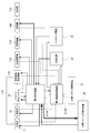
- FIG. 1 It is a block diagram which shows the cremation system concerning the 1st Embodiment of this invention. It is a block diagram of the binary power generation system which comprises the cremation system concerning the 1st Embodiment of this invention. It is a block diagram for demonstrating the electric power control operation
- FIG. 1 It is a graph showing the time change of the total equipment use electric power which totaled the amount of generation of electricity generated with the cremation system of the present invention, and the equipment use electric power of each equipment which constitutes a cremation system.
- FIG. 1 It is a systematic diagram showing an example of composition of a power generation system by the 1st prior art. It is a perspective view showing a mobile type integrated cremation installation by a 2nd prior art. It is a block diagram of the waste heat electric power generating apparatus by 3rd prior art. It is a block diagram showing composition of a power plant of waste heat utilization by the 4th prior art.
- Figure 5 is a block diagram of a fifth prior art binary power generation system;
- FIG. 1 is a block diagram of a cremation system according to a first embodiment of the present invention
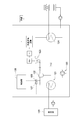
- FIG. 2 is a block diagram of a binary power generation system 19 constituting the cremation system
- FIG. FIG. 4 is an explanatory view for explaining a combustion method in the main burner 11.
- the cremation system according to the present invention comprises a farewell 16 on which the firewood 17 is to be placed, a fire 11 for burning bodies, burials, firewood etc using the fire burner 12, and the exhaust gas from the fire 11
- the refueling furnace 13 for complete combustion and the automatic storage device 15 which can automatically deliver the crucible 17 to the main combustion furnace 12 are provided.
- the exhaust gas from the main burner 11 is led to the binary power generation system 19 through the common flue 18A and the exhaust duct 18B in communication with the reburner 13.
- an exhaust gas auxiliary cooling device / emergency exhaust duct 18C is provided in order to cool the exhaust gas from the common flue 18A and in case of abnormal combustion or the like in the cremation system.
- the exhaust gas led to the exhaust gas / hot water heat exchanger 21 shown in FIG. 2 constituting the binary power generation system 19 exchanges heat with the refrigerant (water) flowing on the outside of the pipe in the exhaust gas / hot water heat exchanger 21 for heat The energy is transmitted and further flows into the hot air recovery heat exchanger 110.
- the inflowing exhaust gas exchanges heat with the air, and the hot air heated by the exhaust gas is guided to the main combustion furnace 11 through the hot air recovery path 116.
- the combustion efficiency of the main combustion furnace 11 can be enhanced, and the fuel can be saved and the combustion time can be shortened.
- the exhaust gas is discharged from the exhaust gas / hot water heat exchanger 21 in the direction of the upper arrow in FIG. 2 and flows into the hot air recovery heat exchanger 110 of FIG.
- the refrigerant is not limited to water, and any medium that exchanges heat with the exhaust gas may be used.
- the exhaust gas flowing out of the hot air recovery heat exchanger 110 flows into the electric precipitator 112 together with the outside air taken in from the air inlet 111 in order to lower the temperature of the exhaust gas, where dust contained in the exhaust gas is removed.
- the exhaust gas that has flowed out of the electrostatic precipitator 112 is sent to the catalytic converter 113, where nitrogen oxides, odorous components, dioxins such as polychlorinated dibenzodioxins and polychlorinated dibenzofurans contained in the exhaust gas are removed.
- the exhaust gas that has flowed out of the catalyst device 113 is sucked by the exhaust fan 114 and exhausted to the atmosphere via the exhaust stack 115.
- the cremation system removes harmful substances such as a large amount of dust and dioxins generated in the main combustion furnace 11, regenerates it into clean air, reduces it to the atmosphere, and reduces the temperature of exhaust gas.
- generating thermal energy using a binary power generation system and supplying the generated power to each device constituting the cremation system it becomes possible to cover part or all of the power required by each device, and the cremation system Energy saving as a whole can be greatly improved.
- the cremation method is roughly divided into four stages, and proceeds in the order of early stage, middle stage, late stage, and end stage, and it takes about 1 hour from cremation start to bone collection, and this cycle is 1 to 7 per furnace per day It is done repeatedly.
- the initial stage about 10 minutes from the start of combustion
- the flame of the main combustion burner 12 is maximized to promote ignition, and the secondary air and the tertiary air supplied from the side wall of the main combustion furnace 11 are supplied more.
- firewood burns more rapidly than in the case of a dead body. For this reason, the temperature of the exhaust gas rises rapidly, and a large amount of exhaust gas is generated temporarily.
- the objects to be burned are changed from firewood to dead bodies and cohesives, and the amount of fat in the dead bodies greatly changes the way of combustion and the exhaust gas flow rate.
- a body with a large amount of fat it burns violently, so the flame size of the main burner 12 is reduced as much as possible, and secondary air and tertiary air from the side wall of the main furnace 11 are maximized and supplied. Control to prevent runaway.
- the exhaust gas flow rate is increased in the case of a fat body, while the body with less fat is weaker in combustion than in the case of a fat body, and the exhaust gas flow rate burns a fat body. It is empirically known that it is about half or less compared to the case of
- the partial remains remaining around the ashes are burned, but if the flame of the main flame burner 12 is too strong it becomes difficult to assimilate as the ashes are broken, so from the flame and the main furnace 11 side wall Control to squeeze both the secondary air and tertiary air supplies.
- the exhaust gas flow rate is reduced to about 1/2 to 1/3 of the peak time.
- the main combustion furnace 11 is air-cooled, and the ashes on the bone tray (not shown) are drawn out to the antechamber 14 and further to the farewell table 16 and collected.
- the exhaust gas flow rate decreases to 0 level.
- the work is performed by sequentially repeating the four stages described above, but in an actual cremation system, generally, two to four cremators are integrally configured as one system. That is, two to four main burners 11, refueling furnace 13, common flue 18A, exhaust duct 18B, exhaust gas auxiliary cooling device and emergency exhaust duct 18C are provided independently, and two to four exhaust ducts 18B are provided.
- Two to four exhaust ducts 18B are provided.
- the cremation start time of each cremator is different, and although the cremation stage (early stage to the end stage) of each cremator is different, cremation is performed in parallel in each system of one cremator. Therefore, when the cremation start time of each cremator overlaps, the quantity of heat of the exhaust gas flowing into the binary power generation system 19 fluctuates by several times as large as the case of one cremator. Although it is possible to suppress fluctuations in the amount of heat of the exhaust gas flowing into the binary power generation system 19 by intentionally shifting the cremation start time, in practice, it is difficult to intentionally shift the cremation start time.
- the power information processor 211B uses this information to stabilize the binary power generation system 19 It may be controlled to generate power efficiently.
- the cremation is divided into four stages in the above to simplify the explanation, in practice the control is finely divided into more stages.
- the main combustion furnace 11, a thermometer for measuring the temperature of the refueling furnace 13, a pressure gauge for measuring the pressure, an oximeter for measuring the oxygen concentration, and a flue gas for measuring the flue gas concentration A densitometer may be provided, and the power information processing apparatus 211B may be configured to control the binary power generation system 19 to generate power stably and efficiently using information from these sensors.
- the binary power generation system 19 will now be described in detail with reference to FIG.
- the exhaust gas from the exhaust duct 18B exchanges heat with the refrigerant (water) in the exhaust gas / hot water heat exchanger 21 to warm the refrigerant.
- the hot water generated in the exhaust gas / hot water heat exchanger 21 is injected into the buffer tank 215A from above the buffer tank 215A, and then drawn by the hot water circulation pump 22A from below the buffer tank 215A and evaporated through the flow control valve 212B. It is sent out (discharged) to the vessel 23.
- Hot water having flowed out of the evaporator 23 is poured into the buffer tank 215B from above the buffer tank 215B, and then sucked by the hot water circulation pump 22D from below the buffer tank 215B and delivered (discharged) to the exhaust gas / hot water heat exchanger 21. Ru.
- the hot water is discharged from the exhaust gas / hot water heat exchanger 21 ⁇ buffer tank 215 A ⁇ hot water circulation pump 22 A ⁇ flow control valve 212 B ⁇ evaporator 23 ⁇ buffer tank 215 B ⁇ hot water circulation pump 22 D ⁇ exhaust gas / hot water heat exchanger 21 It circulates by the route.
- the evaporator 23 heat exchange is performed between the low boiling point working medium such as ammonia, hydrocarbon, isobutane and the like, and the working medium is heated to vaporize the working medium.
- the working medium vapor generated by the evaporator 23 is sent to the medium turbine 24 to drive the medium turbine 24.
- the drive shaft of the medium turbine 24 rotates
- the drive shaft of the generator connected with the drive shaft rotates
- the generator 25 generates power.
- FIG. 2 shows the case where the medium turbine 24 and the generator 25 are configured as independent devices, the medium turbine 24 and the generator 25 may be integrated as a single shaft. Such a configuration makes it possible to miniaturize the binary power generation system.
- the AC power generated by the generator 25 is converted to DC by the high frequency rectifier 26, and further converted to commercial power such as 50 Hz or 60 Hz by the DC / AC converter and output to the power output terminal 28.
- An inverter may be provided on the output side of the generator 25, and the generator 25 may be braked by this inverter to control the rotational speed of the generator 25 to maximize power generation efficiency.
- the working medium vapor from the medium turbine 24 flows into the condenser 29, where heat exchange between the working medium vapor and the cooling water takes place, and the working medium vapor condenses and liquefies.
- the cooling water is circulated between the condenser 29 and the cooling tower 210 by a cooling water circulation pump 22C.
- the cooling water whose temperature has been raised by the condenser 29 is cooled by the cooling tower 210 and returned to the condenser 29 to repeat this cycle, and the condenser 29 stably continues heat exchange with the working medium vapor.
- the cooling water circulation pump 22C receives the control signal from the power information processing device 211B to control the flow rate of the cooling water. That is, the power information processing apparatus 211B performs control so that power generation is stabilized and maximized by signals from the temperature sensor and the pressure sensor provided in the condenser 29.
- the working medium having flowed out of the condenser 29 is sucked by the working medium pump 22B and delivered to the evaporator 23 to exchange heat with hot water again for vaporization.
- Binary power generation is continuously performed by repeating such a cycle.
- the power information processing apparatus 211B controls the flow rate of the working medium using the working medium pump 22B according to the signals from the temperature sensor and pressure sensor provided in the condenser 29, and the output power of the generator 25 is stabilized and the maximum efficiency Control to make it
- the temperature of the hot water delivered from the exhaust gas / hot water heat exchanger 21 to the evaporator 23 generally changes according to the exhaust gas temperature and heat quantity delivered to the exhaust gas / hot water heat exchanger 21, so the exhaust gas / hot water heat exchange
- the temperature of the hot water greatly changes with the change of the exhaust gas temperature and the heat amount sent to the vessel 21. For this reason, if the temperature of the hot water flowing into the evaporator 23 exceeds the allowable value, the operation of the binary power generation system becomes unstable, and in the worst case, the pressure of the working medium vapor extremely increases and the evaporator 23 etc. is destroyed. There is a risk of
- the cremation system of the present invention is provided with two buffer tanks 215A and 215B, and the temperature of the warm water flowing into the buffer tanks 215A and 215B is averaged with the warm water temperature in the buffer tanks 215A and 215B. It is comprised so that the fluctuation of the warm water temperature may be reduced significantly.
- a buffer tank 215A is provided between the exhaust gas / hot water heat exchanger 21 and the hot water circulation pump 22A, and a buffer tank 215B is provided between the evaporator 23 and the hot water circulation pump 22D. Is provided.
- Each buffer tank 215A, 215B is provided with a level meter 216A, 216B for measuring the remaining amount of the warm water in the buffer tank 215A, 215B, in other words, the liquid level of the warm water, and the buffer tank 215A,
- the thermometers 217A and 217B for measuring the warm water temperature in 215B are provided, respectively.
- the temperature signals from the thermometers 217A and 217B are output to the power information processing apparatus 211B, but this signal line is omitted in FIG.
- the signal line is similarly abbreviate
- Hot water from the exhaust gas / hot water heat exchanger 21 is injected from above the buffer tank 215A, and is supplied to the evaporator 23 from below the buffer tank 215A by the hot water circulation pump 22A.
- the hot water from the evaporator 23 is injected from above the buffer tank 215B, and is supplied to the exhaust gas / hot water heat exchanger 21 from the lower side of the buffer tank 215B by the hot water circulation pump 22D.
- the power information processing apparatus 211B constantly monitors the remaining amount of hot water in the buffer tanks 215A and 215B, that is, the liquid level of the hot water, according to the measurement signals from the level meters 216A and 216B.
- the rotational speed of the warm water circulation pump 22A is increased to increase the outflow from the buffer tank 215A, while the rotational speed of the hot water circulation pump 22B is decreased to increase the outflow from the buffer tank 215B. Decrease.
- H1 ⁇ H2 the control reverse to the above is performed.
- the discharge amount of the pumps differs between the two warm water circulation pumps 22A and 22B, and the residual warm water of one buffer tank In the end, the warm water overflows from the buffer tank, and the residual warm water of the other buffer tank continues to decrease, and the residual warm water of the buffer tank can be prevented from being exhausted.
- An effect is obtained.
- a discharge valve (not shown) is provided below the buffer tanks 215A, 215B, and when the measured value of the level meters 216A, 216B provided in the buffer tank reaches the set value, the discharge valve opens and the buffer tank 216A, Automatic control is performed to discharge the warm water of 216B so that the warm water of the buffer tanks 216A and 216B will not overflow. Furthermore, when the discharge valve does not discharge the hot water sufficiently, the hot water in the buffer tanks 216A, 216B is discharged through an overflow nozzle (not shown) provided on the upper side of each of the buffer tanks 216A, 216B. As such, it has double overflow protection.
- the electric power information processing apparatus 211B refers to the thermometers 217A and 217B, and when these temperatures rise and reach respective set values, the water injection valve 214A or the water injection valve 214B is opened, and cold water is supplied from the water injection device 213 to the buffer tank 215A or And / or the buffer tank 215B is controlled so that the temperature of the warm water in the buffer tank 215A and the buffer tank 215B becomes equal to or lower than each set value.
- thermometer 217C for measuring the temperature of the hot water flowing into the evaporator 23
- the water injection valve 214C is opened and the hot water circulation pump 22A is connected via a pipe from the buffer tank 215A.
- Cold water is injected into the hot water flowing to the downstream side, and the temperature of the hot water flowing into the evaporator 23 is controlled to be equal to or lower than a set value.
- the medium is not limited to cold water, and may be a medium for cooling high temperature media, for example It may be a medium which exchanges heat with the exhaust gas in the exhaust gas / hot water heat exchanger 21.
- a bypass flow path is provided between the buffer tank 215A and the evaporator 23, so that the temperature of the hot water from the buffer tank 215A or the amount of heat does not exceed the set value by the power information processing apparatus 211B.
- the flow rate adjustment valve 212B is used to control the flow rate of the hot water flowing into the evaporator 23. Specifically, referring to the thermometer 217D for measuring the temperature Tout of the hot water flowing out of the evaporator 23, the flow rate adjusting valves 212A and 212B are controlled such that the temperature Tout always becomes the set temperature Tout (set value). Do.
- the flow rate adjustment valve 212B is squeezed to suppress the flow rate of hot water flowing into the evaporator 23, and conversely, the flow rate adjustment valve 212A is opened to set the exhaust gas / hot water heat exchanger 21. Control to increase the flow rate of hot water back to the Conversely, when the temperature Tout falls below Tout (set value), the flow control valve 212B is opened to increase the flow rate of hot water flowing into the evaporator 23, and conversely, the flow control valve 212A is squeezed to reduce exhaust gas / It controls so that the flow rate of the warm water which returns directly to warm water heat exchanger 21 is controlled.
- the above control makes it possible to significantly suppress the temperature fluctuation of the hot water flowing into the evaporator 23 against the severe fluctuation of hot water which is a problem unique to the cremation system, and the binary power generation is stably operated. You can do it.
- the power information processing apparatus 211B has the flow control valve 212A.
- the flow control valve 212B is controlled to increase the flow rate of the hot water flowing into the evaporator 23, and the flow control valve 212B is controlled to suppress the flow rate of the hot water returned to the exhaust gas / hot water heat exchanger 21.
- the cremation system according to the present invention is controlled so that the temperature or heat quantity of the hot water flowing into the evaporator 23 becomes constant, so that power generation is stably performed. Therefore, by stably supplying the generated electric power to the devices constituting the cremation system, the entire cremation system can be operated stably at all times.
- the power information processing apparatus 211B is described as controlling the water injection valves 214A, 214B, and 214C using temperature information from the thermometers 217A, 217B, and 217C. Since the heat quantity can be roughly estimated by the time from the cremation start time as described with reference to FIG. 4, the power information processing apparatus 211 B calculates control data in advance using these pieces of information, and the water injection valve 214 A , 214B and 214C may be controlled.
- the present invention is mainly performed by supplying power generated by the binary power generation system 19 to each device configuring the cremation system and various information input from each device to the power information processing device 211 B. Power control of the cremation system of
- FIG. 3 thick lines indicate the flow of power, thin lines indicate control signals, and broken lines indicate detection signals from various sensors mounted in each device.
- Reference numeral 116 denotes a hot air recovery path for blowing the hot air generated in the hot air recovery heat exchanger 110 to the main combustion furnace 11.
- the power control device 211 A and the power information processing device 211 B are described as devices existing outside the binary power generation system 19, the power control device 211 A and the power information processing device 211 B are ones of the binary power generation system 19.
- the power control device 211A and the power information processing device 211B may be configured as part of the cremation system control device 31. Furthermore, the power control device 211A and the power information processing device 211B may be integrally configured.
- the combined configuration of the power control device 211A, the power information processing device 211B, and the cremation system control device 31 can be flexibly performed in accordance with the configuration of hardware, software, and firmware.
- the control of the power information processing apparatus 211B and the cremation system control apparatus 31 is mainly controlled by software, but may be partially controlled by hardware.
- FIG. 3 although the structure which divided the power control apparatus 211A which mainly controls electric power, and the power information processing apparatus 211B which mainly processes an analog signal or a digital signal was demonstrated, the reason is demonstrated.
- the power control unit 211A processes a large amount of power and therefore radiates noise to the periphery. However, if this noise mixes in an analog circuit inside the power information processing unit 211B or a circuit with low noise resistance, these circuits malfunction.
- the control of the power information processing apparatus 211B may malfunction or become unstable.
- the electric power generated by the binary power generation system 19 is used by the power control device 211 A to configure each device that constitutes the cremation system, specifically, the main combustion furnace 11 and the refueling furnace 13.
- Electric apparatus such as hot water circulation pump 22A constituting binary power generation system 19, hot air recovery heat exchanger 110, electric dust collector 112, catalyst device 113, exhaust fan 114, CPU constituting electric power information processing apparatus 211B, electronics such as memory
- the apparatus is supplied to the other device 30 of the cremation system, specifically, the main burner 12 described in FIG.
- the temperature and heat quantity of the exhaust gas discharged from the main combustion furnace 11 and the refueling furnace 13 largely fluctuate, and the binary power generation system 19 according to the present invention controls to minimize the power fluctuation due to the fluctuation. Some variation is inevitable. Therefore, the power required by each device is calculated, and the power from the external power source 32 is added to the power generated by the binary power generation system 19 to supply power to each device for the power for the shortage. Control to stabilize the supply.
- the power generated by the binary power generation system 19 and the power required by each device can be calculated in advance from the operation status of the cremation furnace, and the power information processing apparatus 211B uses this calculated power information to create a cremation Control may be performed so that the entire system and each device constituting the cremation system do not run short of power.
- the backup power supply 33 also has a role of backing up in case the external power supply 32 can not be used temporarily due to an accident or a natural disaster. That is, when the power supply from the external power supply 32 is stopped, the backup power supply 33 is immediately activated by the control signal from the power information processing apparatus 211B or the signal from the external power supply 32, and the power supply to the power control apparatus 211A is an external power supply. Switch from 32 to the backup power supply 33.
- the backup power source 33 is effective in an emergency but is not an essential device for the present cremation system.
- FIG. 5 is a graph showing the time change of the temperature of the reheating furnace in the reheating furnace 13 shown in FIG. 1, in the case where two crematory furnaces operated in parallel, furnace A and furnace B are operated almost simultaneously
- the temperature change of the B furnace is indicated by a broken line by a broken line.
- the exhaust gas from the common flue of the furnace A and the exhaust gas from the common flue of the furnace B are discharged to the common exhaust duct 18 B and flow into the exhaust gas / hot water heat exchanger 21 of the binary power generation system 19. .
- both the main burner 12 and the reburner burner are operated to perform the warm-up operation of the furnace A and the furnace B.
- the warm-up operation of the A furnace and the B furnace is operated for t51 and t51 'hours respectively, and the temperature of each reheat furnace rises to near the set temperature T2 of the reheat furnace by these warm-up operations.
- the temperatures of the respective refueling furnaces 13 After the warm-up operation, the temperatures of the respective refueling furnaces 13 once decrease due to the operation stop of the main combustion burners 12 and the reburning burners, but after that, the operation of the A furnace starts at time t55, and the B furnace at time t55 '.
- the temperature of each refueling furnace 13 rises again to around the temperature T2.
- the heat insulation door provided on the front of the main combustion furnace 11 is opened and the outside air is main The temperature of each refueling furnace 13 is rapidly reduced by flowing into the combustion furnace 11 and the refueling furnace 13.
- the warm-up operation prepared for the second cremation starts again at times t56 'and t56, and the above-described work is repeated thereafter.
- both the main burner 11 and the re-burner 13 are warmed to a certain temperature or higher, so the warm-up operation periods t53 and t53 ′ are significantly larger than the first warm-up operation periods t51 and t51 ′.
- the horizontal axis is the same time axis as FIG. 5, and the timings of warm-up operation, operation of A furnace and B furnace / operation of B furnace are also the same as FIG. 5, and this is the same in FIG. 7 and FIG. .
- the vertical axis represents the exhaust gas flow rate obtained by adding the exhaust gas flow rates from the respective furnaces 13 of furnaces A and B to each other.
- the apparent increase in the exhaust gas flow rate at time t61 means that the heat insulation door on the front of the main combustion furnace 11 is opened when the crucible 17 is put into the main combustion furnace 11. This is to flow into the furnace 11 and the refueling furnace 13.
- the time change of the temperature at the inlet of the evaporator 23, that is, the temperature Tin will be described.
- the temperature Tin continues to rise with the warm-up operation, and further rises rapidly with the start of operation of the furnaces A and B, and reaches the temperature T72. That is, as can be seen from FIG. 6, a large amount of exhaust gas heat is generated at the initial stage of the cremation start, and the heat quantity causes the temperature Tin to rise rapidly from the start of the cremation to time t71.
- the temperature Tin continues to decrease as the exhaust gas heat quantity decreases, and reaches a constant temperature T71 with the start of the warm-up operation, and then rises with the start of the operations of the A furnace and the B furnace, and the above-described operation is repeated.
- the temperature of the hot water flowing into the evaporator 23 is controlled to be stabilized by the above-mentioned mechanism even if the temperature and the exhaust gas flow rate of the exhaust gas change significantly and the heat quantity of the exhaust gas changes significantly. There is. Next, it is estimated about how much the fluctuation rate of temperature Tin is suppressed with respect to the calorie
- the variation rate of the temperature Tin is T72 / ((T71 + T72) / 2) 99%. From this, by the stabilization control of the warm water temperature according to the present invention, the variation can be suppressed to about 9% / 114% 1148% with respect to the variation rate of the warm water temperature when the control to stabilize the warm water temperature is not performed. Recognize.
- the time change of the total facility power consumption obtained by totaling the power generation amount generated by the cremation system of the present invention and the facility power consumption of each facility configuring the cremation system will be described.
- the broken line indicates the amount of power generated by the binary power generation system 19
- the solid line indicates the total facility power consumption.
- the amount of power generation starts to rise at the timing between the end of the warm-up operation of furnace A and B and the cremation start time t55, t55 ', and it is delayed 5 to 15 minutes from the time when temperature Tin reaches the peak in FIG. Reaches a peak around time t81. Thereafter, as can be seen from FIG. 7, the temperature Tin decreases, and in response to this, the power generation amount also decreases, and when the second warm-up operation is started, the power generation amount increases again, and this cycle is repeated thereafter.
- the total installed power peaked sharply with the start of cremation of furnaces A and B. This is because, as can be seen from FIG. 6, the exhaust gas flow reaches a peak during this period, and the power consumption of the exhaust fan 114 sharply increases in order to process this large amount of exhaust gas. After that, the total installed power increases and decreases according to the operation of each facility, but on the average it gradually decreases towards the end of cremation.
- the electric balance in the first cremation is 53%
- the electrical balance in the second cremation is 46%
- the average of the electrical balance in the first and second times is 50%, achieving a highly efficient binary power generation system 19
- the fact that the second electric balance is apparently lower than the first electric balance is a decrease in the temperature Tin during the second warm-up operation due to the short period of the second warm-up operation, as can be seen from FIG. It does not mean that the electricity balance is substantially reduced during cremation operation.
- Second Embodiment A second embodiment of a cremation system according to the present invention will now be described with reference to FIG. Although the case where furnace A and furnace B are simultaneously operated was described above, more generally, a plurality of two or more furnaces of which the timing of operation is independent are arranged in parallel, and these are regarded as one set It may be configured.
- FIG. 9 is a block diagram of a cremation system according to a second embodiment of the present invention, in which a plurality of main burners 11-1 to 11-n and a plurality of reburners 13-1 to 13-n are provided in parallel.
- the exhaust gases from the refueling furnaces 13-1 to 13-n are configured to flow collectively into the binary power generation system 19 '.
- the cremation system according to the present embodiment it is grasped with reference to the information from the sensor at which stage (initial stage to end stage) of the cremation stage described in FIG. This 'information may be used to control the binary power generation system 19' to generate power stably and efficiently.
- thermometers 217A and 217B are provided as thermometers for measuring the warm water temperature of the buffer tanks 215A and 215B.
- the warm water temperature at each warm water inlet of the buffer tanks 215A and 215B and the buffer Separate thermometers may be provided at each hot water inlet and each hot water outlet so as to separately measure the temperature of the hot water at each hot water outlet of the tanks 215A, 215B.
- the effect of the temperature smoothing in the buffer tanks 215A and 215B can be constantly checked in real time, and it can be quickly grasped whether or not the temperature control is normally performed.
Abstract
Description
図1は本発明の第1の実施の形態に係わる火葬システムの構成図、図2は火葬システムを構成するバイナリー発電システム19の構成図、図3は本発明による火葬システムの電力制御動作を説明するためのブロック図であり、図4は主燃炉11での燃焼方法を説明するための説明図である。本発明による火葬システムは、棺17を載置するお別れ台16と、主燃バーナ12を用いて遺体や副葬品、棺などの燃焼を行う主燃炉11と、主燃炉11からの排ガスを完全燃焼させるための再燃炉13と、棺17を主燃炉12に自動で納棺可能とする自動納棺装置15とを備えている。 First Embodiment
FIG. 1 is a block diagram of a cremation system according to a first embodiment of the present invention, FIG. 2 is a block diagram of a binary
図5から排ガス温度は温度T1~T2の範囲で変動することから、変動率はT2/((T1+T2)/2)≒44%となる。 1) Fluctuation of Exhaust Gas Temperature From FIG. 5, since the exhaust gas temperature fluctuates in the range of temperature T1 to T2, the fluctuation rate is T2 / ((T1 + T2) / 2) ≒ 44%.
図6から排ガス流量は流量Q1~Q2の範囲で変動することから、変動率はQ2/((Q1+Q2)/2)≒70%となる。 2) Fluctuation rate of exhaust gas flow rate From FIG. 6, the exhaust gas flow rate fluctuates in the range of flow rates Q1 to Q2, so that the fluctuation rate becomes Q2 / ((Q1 + Q2) / 2) ≒ 70%.
排ガス熱量が(排ガス温度)×(排ガス流量)に比例すると、排ガス熱量の変動率は、44%+70%=114%となる。 3) Fluctuation rate of exhaust gas heat quantity If exhaust gas heat quantity is proportional to (exhaust gas temperature) x (exhaust gas flow rate), fluctuation rate of exhaust gas heat quantity becomes 44% + 70% = 114%.
排ガス熱量の変動率が温水温度の変動率に比例すると、温水温度を安定化する制御を行わないときの温水温度の変動率は114%となる。 4) Fluctuation rate of warm water temperature when control to stabilize warm water temperature is not performed Control of stabilization of warm water temperature is not performed when fluctuating rate of exhaust gas heat quantity is proportional to fluctuation rate of warm water temperature The rate will be 114%.
次に図9を参照して本発明による火葬システムの第2の実施の形態について説明する。上記においてA号炉とB号炉を同時運転する場合について説明したが、より一般的に、運転のタイミングが独立した2炉以上の複数の火葬炉を並列的に配置し、これらを1セットとして構成するようにしても良い。 Second Embodiment
A second embodiment of a cremation system according to the present invention will now be described with reference to FIG. Although the case where furnace A and furnace B are simultaneously operated was described above, more generally, a plurality of two or more furnaces of which the timing of operation is independent are arranged in parallel, and these are regarded as one set It may be configured.
12 主燃バーナ
13, 13-1~13-n再燃炉
14 前室
15 自動納棺装置
16 お別れ台
17 棺
18A 共通煙道
18B 排気ダクト
18C 排ガス補助冷却装置兼非常排気ダクト
19,19’ 排ガス/温水熱交換器を備えたバイナリー発電システム
110 熱風回収熱交換器
111 吸気口
112 電気集塵機
113 触媒装置
114 排風機
115 排気筒
116,116’ 熱風回収路
21 排ガス/温水熱交換器
22A、22D 温水循環ポンプ
22B 作動媒体ポンプ
22C 冷却水循環ポンプ
23 蒸発器
24 媒体タービン
25 発電機
26 高周波整流器
27 DC/ACコンバータ
28 電力出力端子
29 凝縮器
210 冷却塔
211A,211A’ 電力制御装置
211B,211B’ 電力情報処理装置
212A,212B 流量調整バルブ
213 注水装置
214A、214B、214C 注水バルブ
215A、215B バッファタンク
216A、216B レベルメータ
217A、217B、217C、217D 温度計
30 火葬システムの他の装置
31 火葬システム制御装置
32 外部電源
33 バックアップ電源 11, 11-1 to 11-
Claims (12)
- 遺体を燃焼するための燃焼炉と、
前記燃焼炉からの排ガスが流入し、前記排ガスの熱を媒体と熱交換する排ガス/媒体熱交換器と、
前記媒体が注入され、この媒体の温度変動を抑制する第1のバッファタンクと、
前記第1のバッファタンクからの前記媒体の熱により低沸点作動媒体を加熱・蒸発させ作動媒体蒸気を生成する蒸発器と、
前記作動媒体蒸気により駆動される媒体タービンと、
前記媒体タービンにより駆動され発電する発電機と、
火葬システムを構成する各装置に前記発電機で発電した電力と、前記各装置で必要とする電力の不足電力を外部電源から供給する電力制御装置と、
を備える火葬システム。 A combustion furnace for burning the remains,
An exhaust gas / medium heat exchanger in which exhaust gas from the combustion furnace flows in and exchanges heat of the exhaust gas with a medium;
A first buffer tank into which the medium is injected to suppress temperature fluctuations of the medium;
An evaporator that heats and evaporates a low boiling point working medium by the heat of the medium from the first buffer tank to generate working medium vapor;
A medium turbine driven by the working medium vapor;
A generator driven by the medium turbine to generate electricity;
A power control device for supplying power generated by the generator to each device constituting the cremation system and insufficient power of the power required for each device from an external power supply;
Cremation system equipped with. - 前記蒸発器から流出する前記媒体が注入され、この媒体の温度変動を抑制して前記媒体を前記排ガス/媒体熱交換器に供給する第2のバッファタンクを設けることを特徴とする請求項1記載の火葬システム。 2. The apparatus according to claim 1, further comprising a second buffer tank into which the medium flowing out of the evaporator is injected and which supplies the medium to the exhaust gas / medium heat exchanger while suppressing temperature fluctuations of the medium. Cremation system.
- 前記第1のバッファタンク及び前記第2のバッファタンク内の前記媒体の温度がそれぞれ設定温度を超えると、前記各バッファタンク内の前記媒体を冷却するための冷却媒体が前記第1のバッファタンク及び前記第2のバッファタンク内に注入されることを特徴とする請求項2記載の火葬システム。 When the temperature of the medium in the first buffer tank and the second buffer tank exceeds a set temperature, a cooling medium for cooling the medium in each buffer tank is the first buffer tank, and The cremation system according to claim 2, wherein the cremation system is injected into the second buffer tank.
- 前記第1のバッファタンクと前記蒸発器の間に設けられた前記媒体を流す媒体流路に、前記媒体を冷却するための冷却媒体を注入する冷却媒体注入手段を有し、
前記蒸発器に流入する前記媒体の温度が設定温度範囲内となるように前記冷却媒体注入手段を制御することを特徴とする請求項1乃至請求項3記載の火葬システム。 A coolant injection means for injecting a cooling medium for cooling the medium into a medium flow path provided between the first buffer tank and the evaporator for flowing the medium;
The cremation system according to any one of claims 1 to 3, wherein the coolant injection means is controlled such that the temperature of the medium flowing into the evaporator falls within a set temperature range. - 前記第1のバッファタンクと前記蒸発器との間に設けた第1の流量調整バルブと、
前記第1のバッファタンクと前記蒸発器との間から前記排ガス/媒体熱交換器に前記媒体を帰還するバイパス流路と、
前記バイパス流路に設けた第2の流量調整バルブと、を備え、
前記蒸発器から流出する前記媒体の温度が設定温度範囲内となるように前記第1の流量調整バルブと前記第2の流量調整バルブとを制御することを特徴とする請求項1乃至請求項4記載の火葬システム。 A first flow control valve provided between the first buffer tank and the evaporator;
A bypass flow path for returning the medium from between the first buffer tank and the evaporator to the exhaust gas / medium heat exchanger;
And a second flow control valve provided in the bypass flow path,
The first flow control valve and the second flow control valve are controlled such that the temperature of the medium flowing out of the evaporator falls within a set temperature range. Description cremation system. - 前記第1のバッファタンクから流出する前記媒体を吸引して前記蒸発器に送出する第1の媒体循環ポンプと、
前記第2のバッファタンクから流出する前記媒体を吸引して前記前記排ガス/媒体熱交換器に送出する第2の媒体循環ポンプと、
前記第1のバッファタンク及び前記第2のバッファタンク内の各前記媒体の第1液面高さ及び第2液面高さをそれぞれ測定する第1レベルメータ及び第2レベルメータと、を備え、
前記第1液面高さと前記第2液面高さの差が一定値となるように、前記第1の媒体循環ポンプ及び前記第2の媒体循環ポンプがそれぞれ前記媒体の流速を制御することを特徴とする請求項2乃至請求項5記載の火葬システム。 A first medium circulation pump for suctioning the medium flowing out of the first buffer tank and delivering it to the evaporator;
A second medium circulation pump that sucks the medium flowing out of the second buffer tank and sends it to the exhaust gas / medium heat exchanger;
A first level meter and a second level meter that respectively measure a first liquid level height and a second liquid level height of each medium in the first buffer tank and the second buffer tank;
The first medium circulation pump and the second medium circulation pump respectively control the flow velocity of the medium so that the difference between the first liquid level and the second liquid level becomes a constant value. The cremation system according to any one of claims 2 to 5, characterized in that - 前記第1レベルメータ及び第2レベルメータからの信号を参照し、前記第1液面高さと前記第2液面高さがそれぞれ設定値に達したと判断された場合、前記第1のバッファタンク及び前記第2のバッファタンクに設けられた排出バルブが開き、前記第1のバッファタンク及び前記第2のバッファタンク内の前記媒体が排出されることを特徴とする請求項6記載の火葬システム。 When it is determined that the first liquid level and the second liquid level respectively reach set values with reference to the signals from the first level meter and the second level meter, the first buffer tank The cremation system according to claim 6, wherein a discharge valve provided in the second buffer tank is opened, and the medium in the first buffer tank and the second buffer tank is discharged.
- 前記火葬システムに設けた各種センサからの情報を演算して制御信号を生成し、この制御信号により前記火葬システムを構成する各装置のうちの少なくとも一つの装置を制御する電力情報処理装置を設けることを特徴とする請求項1乃至請求項7記載の火葬システム。 Providing a power information processing apparatus for calculating at least one of the devices constituting the cremation system by calculating information from various sensors provided in the cremation system to generate a control signal, and using the control signal. The cremation system according to any one of claims 1 to 7, characterized in that
- 前記火葬炉が並列に複数設けられ、前記火葬炉からの各排ガスが共通の前記排ガス/媒体熱交換器に流入することを特徴とする請求項1又は請求項8記載の火葬システム。 The cremation system according to claim 1 or 8, wherein a plurality of the cremators are provided in parallel, and each exhaust gas from the cremators flows into the common exhaust gas / medium heat exchanger.
- 前記排ガス/媒体熱交換器から排出された排ガスの熱を空気と熱交換し熱風を生成する熱風回収熱交換器と、
前記熱風を前記火葬炉に送出する熱風回収路と、を備える請求項1乃至請求項9記載の火葬システム。 A hot air recovery heat exchanger that exchanges heat of exhaust gas discharged from the exhaust gas / medium heat exchanger with air to generate hot air;
The cremation system according to any one of claims 1 to 9, further comprising: a hot air recovery path for delivering the hot air to the cremation furnace. - 前記火葬炉の燃焼段階の情報を参照して、前記排ガス/媒体熱交換器、前記蒸発器、前記媒体タービン、前記発電機、前記冷却媒体注入手段、前記第1の流量調整バルブ、前記第2の流量調整バルブ、前記第1の媒体循環ポンプ、前記第2の媒体循環ポンプ、前記第1のバッファタンク及び前記第2のバッファタンクに前記冷却媒体を注入する手段の少なくとも一つを制御することを特徴とする請求項6記載の火葬システム。 The exhaust gas / medium heat exchanger, the evaporator, the medium turbine, the generator, the cooling medium injection means, the first flow rate adjusting valve, the second flow rate adjusting valve, and the second flow rate adjusting valve with reference to information of the burning stage of the cremation furnace. Controlling at least one of the flow control valve, the first medium circulation pump, the second medium circulation pump, the first buffer tank, and the means for injecting the cooling medium into the second buffer tank. The cremation system of Claim 6 characterized by the above-mentioned.
- 前記外部電源に異常が発生した場合に備えるバックアップ電源を設け、前記外部電源からの電力が停止又は低下した場合は、前記外部電源から前記バックアップ電源に切り替えることを特徴とる請求項1乃至請求項11記載の火葬システム。 A backup power supply is provided in case an abnormality occurs in the external power supply, and the power supply from the external power supply is switched to the backup power supply when the power from the external power supply is stopped or decreased. Description cremation system.
Priority Applications (5)
| Application Number | Priority Date | Filing Date | Title |
|---|---|---|---|
| KR1020157016912A KR101726730B1 (en) | 2012-12-03 | 2013-11-25 | Cremation system |
| US14/648,508 US9822972B2 (en) | 2012-12-03 | 2013-11-25 | Cremation system |
| EP13860392.3A EP2940385B1 (en) | 2012-12-03 | 2013-11-25 | Cremation system |
| JP2014514995A JP5579346B1 (en) | 2012-12-03 | 2013-11-25 | Cremation system |
| CN201380063068.8A CN104870899B (en) | 2012-12-03 | 2013-11-25 | cremation system |
Applications Claiming Priority (2)
| Application Number | Priority Date | Filing Date | Title |
|---|---|---|---|
| JP2012263922 | 2012-12-03 | ||
| JP2012-263922 | 2012-12-03 |
Publications (1)
| Publication Number | Publication Date |
|---|---|
| WO2014087864A1 true WO2014087864A1 (en) | 2014-06-12 |
Family
ID=50883287
Family Applications (1)
| Application Number | Title | Priority Date | Filing Date |
|---|---|---|---|
| PCT/JP2013/081618 WO2014087864A1 (en) | 2012-12-03 | 2013-11-25 | Cremation system |
Country Status (6)
| Country | Link |
|---|---|
| US (1) | US9822972B2 (en) |
| EP (1) | EP2940385B1 (en) |
| JP (1) | JP5579346B1 (en) |
| KR (1) | KR101726730B1 (en) |
| CN (1) | CN104870899B (en) |
| WO (1) | WO2014087864A1 (en) |
Families Citing this family (2)
| Publication number | Priority date | Publication date | Assignee | Title |
|---|---|---|---|---|
| ES2736159B2 (en) * | 2019-10-30 | 2022-12-22 | Univ La Rioja | Operation procedure of an energetically improved crematorium oven and electrical energy storage burial urn |
| KR102417097B1 (en) * | 2021-10-26 | 2022-07-06 | 최병렬 | blue hydrogen production device using natural gas, liquefied device for waste gas generated during combustion of raw materials, and steam turbine power generation device using high-temperature steam |
Citations (8)
| Publication number | Priority date | Publication date | Assignee | Title |
|---|---|---|---|---|
| JPS526853A (en) * | 1975-07-07 | 1977-01-19 | Shigeji Sugaya | Constant output electric generating technique and plant by burninc up city trashes |
| JPH10184316A (en) | 1996-12-24 | 1998-07-14 | Toshiba Corp | Power generation control device utilizing exhaust heat |
| JP2002060759A (en) * | 2000-08-22 | 2002-02-26 | Toshiba Corp | Apparatus for treating waste plastic |
| JP2009221961A (en) | 2008-03-17 | 2009-10-01 | Fuji Electric Holdings Co Ltd | Binary power generating system |
| JP2010133693A (en) | 2008-12-05 | 2010-06-17 | Jin-Shin Park | Mobile integrated cremation equipment |
| JP2012013266A (en) | 2010-06-29 | 2012-01-19 | Taisho Densetsu Co Ltd | Power generation system, and cremator |
| JP4875546B2 (en) | 2007-06-13 | 2012-02-15 | 株式会社荏原製作所 | Exhaust heat power generation apparatus and method for controlling working medium vapor superheat degree of exhaust heat power generation apparatus |
| JP2013124568A (en) * | 2011-12-14 | 2013-06-24 | Takuma Co Ltd | Waste power generation system |
Family Cites Families (12)
| Publication number | Priority date | Publication date | Assignee | Title |
|---|---|---|---|---|
| US1800959A (en) * | 1925-04-29 | 1931-04-14 | Ruths Accumulator Aktiebolag | Steam plant |
| FR2166505A5 (en) | 1971-12-28 | 1973-08-17 | Rhone Poulenc Sa | Carbone from alpha-pinene - by oxidn with performic acid to hydroxy-8-carvotanacetone and dehydration |
| CN86206663U (en) * | 1986-09-03 | 1987-07-29 | 中国人民解放军7433工厂 | Movable crematory vehcile |
| JP2957627B2 (en) * | 1990-03-15 | 1999-10-06 | 大阪瓦斯株式会社 | Municipal waste incineration melting equipment |
| JPH0518212A (en) * | 1991-07-11 | 1993-01-26 | Toshiba Corp | Waste heat utilizing power generation control device |
| JP3847962B2 (en) * | 1997-07-30 | 2006-11-22 | 株式会社東芝 | Power plant heating water heating system |
| US6973789B2 (en) * | 1998-11-10 | 2005-12-13 | Ormat Technologies, Inc. | Method of and apparatus for producing power in remote locations |
| US6436337B1 (en) * | 2001-04-27 | 2002-08-20 | Jupiter Oxygen Corporation | Oxy-fuel combustion system and uses therefor |
| JP2003314365A (en) * | 2002-04-18 | 2003-11-06 | Ishikawajima Harima Heavy Ind Co Ltd | Reuse method and device for thermal decomposition gas |
| JP4186181B2 (en) * | 2002-08-29 | 2008-11-26 | 株式会社日立製作所 | Cogeneration method and cogeneration system |
| KR101027045B1 (en) * | 2010-12-09 | 2011-04-06 | 주식회사 대경에스코 | Unified cremator system |
| CA3169637A1 (en) * | 2011-03-14 | 2012-09-20 | Pyrogenesis Canada Inc. | Method to maximize energy recovery in waste-to-energy processes |
-
2013
- 2013-11-25 CN CN201380063068.8A patent/CN104870899B/en active Active
- 2013-11-25 JP JP2014514995A patent/JP5579346B1/en active Active
- 2013-11-25 WO PCT/JP2013/081618 patent/WO2014087864A1/en active Application Filing
- 2013-11-25 US US14/648,508 patent/US9822972B2/en active Active
- 2013-11-25 EP EP13860392.3A patent/EP2940385B1/en active Active
- 2013-11-25 KR KR1020157016912A patent/KR101726730B1/en active IP Right Grant
Patent Citations (8)
| Publication number | Priority date | Publication date | Assignee | Title |
|---|---|---|---|---|
| JPS526853A (en) * | 1975-07-07 | 1977-01-19 | Shigeji Sugaya | Constant output electric generating technique and plant by burninc up city trashes |
| JPH10184316A (en) | 1996-12-24 | 1998-07-14 | Toshiba Corp | Power generation control device utilizing exhaust heat |
| JP2002060759A (en) * | 2000-08-22 | 2002-02-26 | Toshiba Corp | Apparatus for treating waste plastic |
| JP4875546B2 (en) | 2007-06-13 | 2012-02-15 | 株式会社荏原製作所 | Exhaust heat power generation apparatus and method for controlling working medium vapor superheat degree of exhaust heat power generation apparatus |
| JP2009221961A (en) | 2008-03-17 | 2009-10-01 | Fuji Electric Holdings Co Ltd | Binary power generating system |
| JP2010133693A (en) | 2008-12-05 | 2010-06-17 | Jin-Shin Park | Mobile integrated cremation equipment |
| JP2012013266A (en) | 2010-06-29 | 2012-01-19 | Taisho Densetsu Co Ltd | Power generation system, and cremator |
| JP2013124568A (en) * | 2011-12-14 | 2013-06-24 | Takuma Co Ltd | Waste power generation system |
Also Published As
| Publication number | Publication date |
|---|---|
| KR20150092195A (en) | 2015-08-12 |
| CN104870899B (en) | 2017-03-08 |
| US9822972B2 (en) | 2017-11-21 |
| US20150308678A1 (en) | 2015-10-29 |
| CN104870899A (en) | 2015-08-26 |
| EP2940385B1 (en) | 2019-04-10 |
| JPWO2014087864A1 (en) | 2017-01-05 |
| JP5579346B1 (en) | 2014-08-27 |
| EP2940385A1 (en) | 2015-11-04 |
| KR101726730B1 (en) | 2017-04-13 |
| EP2940385A4 (en) | 2016-10-26 |
Similar Documents
| Publication | Publication Date | Title |
|---|---|---|
| JP6034154B2 (en) | Waste heat recovery equipment, waste heat recovery method and waste treatment furnace | |
| EP2482958B1 (en) | Power plant for co2 capture | |
| JP4972421B2 (en) | Heat pump steam / hot water generator | |
| US9476325B2 (en) | Method and apparatus of producing and utilizing thermal energy in a combined heat and power plant | |
| ES2828057T3 (en) | Installation of thermal energy recovery in a beam furnace and its conversion into electricity using a turbine that generates electricity through the implementation of a Rankine cycle | |
| JP2005534883A (en) | Waste heat steam generator | |
| JP2016180528A (en) | Waste treatment facility, and operating method of waste treatment facility | |
| CN106089341A (en) | Strengthen the method that in many gas turbines combined cycle power plant, cold steamturbine starts | |
| JP2018533712A (en) | Method and equipment for utilization of water heater waste heat recovery by built-in high temperature water source heat pump | |
| JP6522085B1 (en) | Heat recovery power generation equipment from flue gas and control method thereof | |
| CN109339877A (en) | A kind of coal base distributing-supplying-energy system | |
| WO2014087864A1 (en) | Cremation system | |
| JP2014009624A (en) | Waste heat utilization method, waste heat utilization system and treatment method of boiler exhaust gas | |
| JP5818307B2 (en) | Boiler equipment and method for controlling gas temperature at outlet thereof | |
| JP5438146B2 (en) | Pressurized flow furnace system | |
| JP2000054855A (en) | External heating type gas turbine | |
| JP2011149434A (en) | Gas turbine combined power generation system | |
| JP5137598B2 (en) | Ventilation system in steam power generation facilities | |
| TWI613399B (en) | Cremation system | |
| JP5491550B2 (en) | Pressurized flow furnace system and control method thereof | |
| JP2007526976A5 (en) | ||
| JP2007183025A (en) | Water cooling and heating system | |
| WO2013050803A1 (en) | Organic rankine cycle power plant | |
| JP5807903B2 (en) | Heat recovery utilization method and heat recovery utilization system of intermittent operation type waste incineration facility | |
| JP2005121332A (en) | Double effect absorption type water cooling and heating machine with exhaust heat recovery device |
Legal Events
| Date | Code | Title | Description |
|---|---|---|---|
| ENP | Entry into the national phase |
Ref document number: 2014514995 Country of ref document: JP Kind code of ref document: A |
|
| 121 | Ep: the epo has been informed by wipo that ep was designated in this application |
Ref document number: 13860392 Country of ref document: EP Kind code of ref document: A1 |
|
| WWE | Wipo information: entry into national phase |
Ref document number: 14648508 Country of ref document: US |
|
| NENP | Non-entry into the national phase |
Ref country code: DE |
|
| ENP | Entry into the national phase |
Ref document number: 20157016912 Country of ref document: KR Kind code of ref document: A |
|
| WWE | Wipo information: entry into national phase |
Ref document number: 2013860392 Country of ref document: EP |