WO2014080733A1 - 組立作業性評価計算装置、および組立作業性評価方法 - Google Patents
組立作業性評価計算装置、および組立作業性評価方法 Download PDFInfo
- Publication number
- WO2014080733A1 WO2014080733A1 PCT/JP2013/079500 JP2013079500W WO2014080733A1 WO 2014080733 A1 WO2014080733 A1 WO 2014080733A1 JP 2013079500 W JP2013079500 W JP 2013079500W WO 2014080733 A1 WO2014080733 A1 WO 2014080733A1
- Authority
- WO
- WIPO (PCT)
- Prior art keywords
- assembly
- evaluation
- workability
- component
- posture
- Prior art date
- Legal status (The legal status is an assumption and is not a legal conclusion. Google has not performed a legal analysis and makes no representation as to the accuracy of the status listed.)
- Ceased
Links
Images





Classifications
-
- G—PHYSICS
- G05—CONTROLLING; REGULATING
- G05B—CONTROL OR REGULATING SYSTEMS IN GENERAL; FUNCTIONAL ELEMENTS OF SUCH SYSTEMS; MONITORING OR TESTING ARRANGEMENTS FOR SUCH SYSTEMS OR ELEMENTS
- G05B19/00—Program-control systems
- G05B19/02—Program-control systems electric
- G05B19/18—Numerical control [NC], i.e. automatically operating machines, in particular machine tools, e.g. in a manufacturing environment, so as to execute positioning, movement or co-ordinated operations by means of program data in numerical form
- G05B19/4097—Numerical control [NC], i.e. automatically operating machines, in particular machine tools, e.g. in a manufacturing environment, so as to execute positioning, movement or co-ordinated operations by means of program data in numerical form characterised by using design data to control NC machines, e.g. CAD/CAM
-
- G—PHYSICS
- G05—CONTROLLING; REGULATING
- G05B—CONTROL OR REGULATING SYSTEMS IN GENERAL; FUNCTIONAL ELEMENTS OF SUCH SYSTEMS; MONITORING OR TESTING ARRANGEMENTS FOR SUCH SYSTEMS OR ELEMENTS
- G05B19/00—Program-control systems
- G05B19/02—Program-control systems electric
- G05B19/418—Total factory control, i.e. centrally controlling a plurality of machines, e.g. direct or distributed numerical control [DNC], flexible manufacturing systems [FMS], integrated manufacturing systems [IMS] or computer integrated manufacturing [CIM]
- G05B19/41805—Total factory control, i.e. centrally controlling a plurality of machines, e.g. direct or distributed numerical control [DNC], flexible manufacturing systems [FMS], integrated manufacturing systems [IMS] or computer integrated manufacturing [CIM] characterised by assembly
-
- G—PHYSICS
- G06—COMPUTING OR CALCULATING; COUNTING
- G06F—ELECTRIC DIGITAL DATA PROCESSING
- G06F30/00—Computer-aided design [CAD]
-
- G—PHYSICS
- G06—COMPUTING OR CALCULATING; COUNTING
- G06F—ELECTRIC DIGITAL DATA PROCESSING
- G06F30/00—Computer-aided design [CAD]
- G06F30/10—Geometric CAD
-
- G—PHYSICS
- G06—COMPUTING OR CALCULATING; COUNTING
- G06F—ELECTRIC DIGITAL DATA PROCESSING
- G06F30/00—Computer-aided design [CAD]
- G06F30/10—Geometric CAD
- G06F30/17—Mechanical parametric or variational design
-
- G—PHYSICS
- G06—COMPUTING OR CALCULATING; COUNTING
- G06T—IMAGE DATA PROCESSING OR GENERATION, IN GENERAL
- G06T19/00—Manipulating three-dimensional [3D] models or images for computer graphics
- G06T19/20—Editing of three-dimensional [3D] images, e.g. changing shapes or colours, aligning objects or positioning parts
-
- G—PHYSICS
- G05—CONTROLLING; REGULATING
- G05B—CONTROL OR REGULATING SYSTEMS IN GENERAL; FUNCTIONAL ELEMENTS OF SUCH SYSTEMS; MONITORING OR TESTING ARRANGEMENTS FOR SUCH SYSTEMS OR ELEMENTS
- G05B2219/00—Program-control systems
- G05B2219/30—Nc systems
- G05B2219/31—From computer integrated manufacturing till monitoring
- G05B2219/31052—Find feasable assembly sequences
-
- G—PHYSICS
- G05—CONTROLLING; REGULATING
- G05B—CONTROL OR REGULATING SYSTEMS IN GENERAL; FUNCTIONAL ELEMENTS OF SUCH SYSTEMS; MONITORING OR TESTING ARRANGEMENTS FOR SUCH SYSTEMS OR ELEMENTS
- G05B2219/00—Program-control systems
- G05B2219/30—Nc systems
- G05B2219/32—Operator till task planning
- G05B2219/32104—Data extraction from geometric models for process planning
-
- G—PHYSICS
- G05—CONTROLLING; REGULATING
- G05B—CONTROL OR REGULATING SYSTEMS IN GENERAL; FUNCTIONAL ELEMENTS OF SUCH SYSTEMS; MONITORING OR TESTING ARRANGEMENTS FOR SUCH SYSTEMS OR ELEMENTS
- G05B2219/00—Program-control systems
- G05B2219/30—Nc systems
- G05B2219/35—Nc in input of data, input till input file format
- G05B2219/35197—Assemblability
-
- G—PHYSICS
- G06—COMPUTING OR CALCULATING; COUNTING
- G06F—ELECTRIC DIGITAL DATA PROCESSING
- G06F2111/00—Details relating to CAD techniques
- G06F2111/04—Constraint-based CAD
-
- G—PHYSICS
- G06—COMPUTING OR CALCULATING; COUNTING
- G06F—ELECTRIC DIGITAL DATA PROCESSING
- G06F2111/00—Details relating to CAD techniques
- G06F2111/20—Configuration CAD, e.g. designing by assembling or positioning modules selected from libraries of predesigned modules
-
- G—PHYSICS
- G06—COMPUTING OR CALCULATING; COUNTING
- G06T—IMAGE DATA PROCESSING OR GENERATION, IN GENERAL
- G06T2219/00—Indexing scheme for manipulating 3D models or images for computer graphics
- G06T2219/20—Indexing scheme for editing of 3D models
- G06T2219/2008—Assembling, disassembling
-
- Y—GENERAL TAGGING OF NEW TECHNOLOGICAL DEVELOPMENTS; GENERAL TAGGING OF CROSS-SECTIONAL TECHNOLOGIES SPANNING OVER SEVERAL SECTIONS OF THE IPC; TECHNICAL SUBJECTS COVERED BY FORMER USPC CROSS-REFERENCE ART COLLECTIONS [XRACs] AND DIGESTS
- Y02—TECHNOLOGIES OR APPLICATIONS FOR MITIGATION OR ADAPTATION AGAINST CLIMATE CHANGE
- Y02P—CLIMATE CHANGE MITIGATION TECHNOLOGIES IN THE PRODUCTION OR PROCESSING OF GOODS
- Y02P90/00—Enabling technologies with a potential contribution to greenhouse gas [GHG] emissions mitigation
- Y02P90/02—Total factory control, e.g. smart factories, flexible manufacturing systems [FMS] or integrated manufacturing systems [IMS]
Definitions
- the present invention relates to an assembly workability evaluation calculation device and an assembly workability evaluation method.
- Patent Document 1 There is Japanese Patent No. 3391648 (Patent Document 1) as background art in this technical field.
- Patent Document 1 “Regarding the operability improvement technology of the equipment operability evaluation apparatus using a human body model, the reference position of the human body model placed in the simulation space is defined according to the basic posture of the human body model, When the human body model is changed to a different body type, the changed human body model is arranged in the simulation space so that the basic positions match before and after the change.
- Patent Document 2 Japanese Patent No. 4136673
- This gazette describes “a technique for verifying the safety of equipment by using a device image and a worker model and using a visual field image viewed from the viewpoint of the worker model in a virtual three-dimensional space.
- Equipment placement section that places the equipment model to be verified in space, viewing angle designation section that designates the viewing angle of the worker model, opening position designation section that designates the position of the opening of the equipment model, viewpoint of the worker model A viewpoint position designating section for designating a position, an operator placement section for placing the worker model in the virtual three-dimensional space based on the position of the opening or the viewpoint position, and the gaze direction of the worker model downward in the vertical direction
- a visual field image display unit that obtains a range of the visual field image when viewed from the viewpoint of the worker model using the visual field angle and displays the visual field image of the range. ” .
- JP 2012-14569 A states that “an assembly sequence generation system that generates an assembly sequence for sequentially assembling a plurality of parts that constitute an assembly, Component placement / proximity relationship acquisition unit that acquires information on proximity relationship with parts from CAD, assembly unit setting unit that sets assembly units of multiple components, and component placement and components acquired by component placement / proximity relationship acquisition unit An assembly sequence generation unit that generates an assembly sequence of a plurality of parts without interfering with adjacent parts from the proximity relationship and the assembly unit set by the assembly unit setting unit, and a plurality of assembly sequences generated by the assembly sequence generation unit And an assembly animation generation unit for generating a camera viewpoint for observing the assembly operation. " That.
- Patent Document 4 states that “in order to improve product productivity, a designed structure of the product is manufactured based on design information created using CAD or the like. Disclosed is a manufacturability automatic evaluation method and system that quantitatively evaluates whether or not it is a structure that is particularly easy to assemble, and its configuration evaluates ease of making such as assemblability and workability, Computer system for presenting improvement examples, processing routine for estimating assembly order, processing routine for determining optimal assembly order, assembly method, processing method, etc. from results of calculating assembly method, processing method, etc., and improvement example ”, A routine for outputting results, and an improved example database for automatically accumulating evaluation results and design information”.
- Japanese Patent No. 3391648 Japanese Patent No. 4136673 JP 2012-14569 A Japanese Patent Laid-Open No. 5-114003
- Patent Document 1 and Patent Document 2 it is necessary to place a human body model (worker model) on a device model to be verified in a virtual space and operate the model to verify workability.
- the object of the present invention is to estimate the position and orientation of the worker from the assembly procedure and operation of the parts based on the product model information to be verified, and to evaluate the ergonomics such as visibility, working posture and reachability during assembly work Therefore, it is desirable to provide an assembly workability evaluation calculation apparatus and an assembly workability evaluation method that automatically calculate the assemblyability evaluation of a product at the design stage without the evaluator placing and manipulating the human body model.
- an assembling workability evaluation calculation device for evaluating assembly workability and workability of assembling work for sequentially assembling a plurality of parts constituting an assembly, and a component attribute of each of the plurality of parts, Information acquisition means for extracting information on the adjacent relationship between the part arrangement and other parts from the 3D CAD model acquired from CAD, part type classification and feature shape detection means for classifying the part type from the acquired 3D CAD model information, Based on the adjacency information between parts in the 3D CAD model information, a means for expressing the relation between the parts in a graph with the parts as nodes and the adjacency as edges, and a direction that can be decomposed based on the assembly graph are generated.
- Comprehensive evaluation means for calculating a comprehensive evaluation value of the sex and outputting the result is configured.
- each part attribute of the plurality of parts Extracting the information of the adjacent relationship between the part arrangement and other parts from the 3D CAD model acquired from CAD, classifying the part type from the acquired 3D CAD model information, and detecting the feature shape, and the 3D CAD model From the information on the adjacent relationship between components in the information, a process of expressing the relationship between components in a graph with the component as a node and the adjacent relationship as an edge, and a decomposable direction based on the assembly graph are generated and decomposed By generating the direction and disassembly order, the inverse transformation is performed to derive the assembly order and the assembly direction, and the basic deduction points Ex for each part assembly operation are corrected.
- a process for generating a correct worker position / posture / viewpoint, a process for evaluating workability at the generated worker position / posture / viewpoint, an evaluation value of an index of ease of assembly of the parts, and an assembly workability And a comprehensive evaluation step of calculating a comprehensive evaluation value and outputting the result.
- the present invention by using the model information to be verified, by automatically evaluating the position, posture, and line of sight of the worker with respect to the assembly motion, it is easy to assemble parts, the fatigue level of the worker, It is possible to perform automatic evaluation from multiple viewpoints of the user's mobility, and the effect of shortening the verification time of assembly evaluation at the design stage and reducing design rework can be obtained. Problems, configurations, and effects other than those described above will be clarified by the following description of embodiments.
- an assembly graph is generated for each part feature and the adjacency relationship between parts to generate an assembly sequence, an assembly direction, and an operation.
- An assembly workability evaluation calculation apparatus 100 that performs evaluation of parts assembling operation and ergonomic evaluation according to the procedure will be described.
- FIG. 1 shows an example of a schematic overall configuration diagram of an assembly workability evaluation calculation apparatus 100 as an assemblyability evaluation system applied in the first embodiment of the present invention.
- the assembling workability evaluation calculation apparatus 100 includes an input unit 140 for inputting setting information necessary for analysis, such as a keyboard and a mouse, a selection instruction or other instructions on a menu, and display and input of an evaluation target model.
- Display unit 150 that displays information, process results, process background, etc., and acquires adjacency relationships based on 3D CAD data, generates assembly order, direction, and operation, and parts assembly operation Control unit 110 that executes processing of evaluation, ergonomic evaluation, and output of the result, storage unit 130 that stores 3D CAD data, analysis program, calculation conditions, calculation results, and the like, and is externally connected via network 210
- the communication unit 160 receives 3D CAD data from the 3D CAD device 200.
- control unit 110 includes a CPU (Central Processing Unit), ROM (Read Only Memory), RAM (Random Access Memory), and the storage unit 130 is configured by an external storage device such as a hard disk device.
- the input unit 140 may use a touch panel, a dedicated switch or sensor, or a voice recognition device.
- the display unit 150 uses a device that displays information on a screen or a screen, such as a display, a projector, or a head mounted display.
- a printer (not shown) that outputs information displayed on the display unit 150 to a sheet may be connected to the assembly workability evaluation calculation apparatus 100. Note that these hardware configurations need not be dedicated devices, and a general computer system such as a personal computer can be used.
- the control unit 110 of the assembly workability evaluation calculation device 100 includes a 3D CAD model information acquisition unit 111, a component type classification and feature shape detection unit 112, an assembly graph generation unit 113, and an assembly sequence / direction / operation.
- Generation means 114 workpiece coordinate system calculation means 115, part assembly operation evaluation calculation means 116, a plurality of worker position / posture / viewpoint setting means 117, ergonomics evaluation means 120, and assembly workability And a comprehensive evaluation means 118.
- the ergonomics evaluation means 120 for evaluating the ease of work and fatigue of the operator includes a visibility evaluation means 121, a work posture / line of sight evaluation means 122, a reachability evaluation means 123, a flow line and a posture. Change evaluation means 124.
- the storage unit 130 of the assembly workability evaluation calculation device 100 includes 3D CAD model information (evaluation target model: assembly) obtained from the 3D CAD device, 3D CAD model information 131 in a table format extracted from the information, and classification and characteristics of the component types.
- 3D CAD model information evaluation target model: assembly
- each storage area of work posture / line-of-sight evaluation information 138 for storing scores for combinations of assumed data values in a table format and reachability evaluation function 139 for defining an evaluation function to be referred to in reachability evaluation processing Is provided.
- FIG. 2 is an example of a flowchart for explaining a procedure until the assembly workability evaluation calculation apparatus 100 outputs a comprehensive evaluation result of assembly workability based on 3D CAD data obtained from the 3D CAD apparatus 200.
- the 3D CAD model information (evaluation target model: assembly) obtained from the 3D CAD apparatus 200 and stored in the storage unit 130 is read, the component configuration of the assembly, and each component 3, the model name and dimensions, the component attributes such as the component center position and the component centroid position, and the information on the adjacency relationship between the components, and the table format 3D CAD model information 131 shown in FIG. To store.
- the evaluation target is an assembly model that is an assembly composed of a plurality of parts.
- the part attributes and shape features in the classification column of FIG. 3 are part ID, layer number, model name, part figure number, part title, part volume, surface area, material, specific gravity, mass, maximum length, center of gravity, and bounding box. (Coordinates of eight vertices of a rectangular parallelepiped serving as a boundary surrounding the part), main moment of inertia, principal axis of inertia, and the like are extracted.
- the component arrangement is the position and orientation of each component on the assembly model arranged in the world coordinate system, and is composed of the three axes X, Y, Z of the component coordinate system of each component and the component origin.
- the part configuration is information indicating a parent-child relationship between a part of the 3D CAD model and a part.
- the data items include a parent part ID, a child part ID, a flag indicating a subassembly, and a flag indicating non-target (3DCAD On the model, there is information indicating non-display and suppression).
- the adjacent relationship between parts is assembly constraint information set when modeling an assembly model.
- the assembly constraint information is preferably obtained by not only information set by the designer at the time of modeling but also by clearance analysis between parts based on the assembly model.
- one method of clearance analysis is to search for another model within the clearance distance from each surface of the modeled part based on the set threshold value, and to find the surface of the adjacent part (plane, cylinder)
- the constraint surface information obtained from assembly constraint and clearance analysis information is obtained when the plane is a constraint surface normal vector facing the outside of the model and the point on the surface at the constraint surface origin. Uses the axial direction of the cylinder as the constraint surface normal vector and the point on the axis as the constraint surface origin.
- the modeling operation of the 3D CAD model and the operation of specifying the model to be analyzed are omitted.
- the component type classification and feature shape detection processing in step S20 in FIG. 2 reads the component type information 132 in the storage unit 130, and specifies the condition of the specified model name (eg, a character string in which the first character is specified) or the like.
- the component type of each component stored in the 3D CAD model information 131 acquired in step S10 is determined based on the specified component dimensions (eg, below the specified dimension).
- FIG. 4 is an example of the component type information 132 stored in the storage unit 130, and is used in the determination in step S20.
- the part type table 132 includes 3D CAD part attributes (model name, part figure number, part title) and 3D CAD shape feature determination condition items as information for assigning the part type, and the part type in the allocation condition for each row.
- the name and the matching degree are identified by the component type ID.
- retrieval is performed using an item other than a blank as a condition in the allocation condition of each row.
- the part diagram number and the part title are text information arbitrarily defined by the user in the 3D CAD part model or assembly model.
- a character string including a wildcard character (such as *) indicating an arbitrary character is stored.
- a character string condition column may be added to define conditions such as complete match, forward match, and backward match.
- mass characteristics that can be acquired by calculating a 3D CAD model such as the bounding box vertex, the center of gravity, and the main inertia moment in the part model may be stored in addition to the example of the dimensional condition.
- conditions indicating ranges such as equal, below, and larger are set, and the conditions can be set by AND and OR conditions.
- the assembly graph generation process in step S30 in FIG. 2 is a graph in which the component is a node (node) and the adjacent relationship is an edge (side) from the adjacent relationship information between components of the 3D CAD model information acquired in step S10. Create data that represents the relationship between parts.
- FIG. 5 shows an example of a 3D CAD model, where there are a part B and a part C on the part A, the part B is fastened to the part A with two screws AB, and the part C is a part A in a PONCH shape (alignment mark). And is welded.
- the part D is fastened with a part B and two screws BD, and the part C is fastened with two screws CD.
- the part E is inserted into the hole of the part A and the hole of the part D.
- the coordinate system shown at the lower left of the model is the world coordinate system. The following description is based on this model.
- FIG. 6 is an example of an assembly graph generated from the adjacent relationship between parts for the 3D CAD model shown in FIG. This is a graph representation in which a component is a node and an adjacent relationship between components is an edge, and an edge is generated for each type of adjacent relationship (for each type of adjacent direction and adjacent surface). Further, the plane constraint (plane matching) and the cylindrical constraint (coaxial) are largely distinguished, and the plane constraint is indicated by P and the cylindrical constraint is indicated by C on the edge of FIG.
- the model name has the same name and the assembly direction is the same and the adjacency relationship is the same (the adjoining direction and the adjoining surface are the same)
- even a plurality of parts are shown as one node (example: screw AB). , Screw BD, screw CD, etc.).
- the created assembly graph is stored in the storage unit 130.
- step S30 is generated based on the assembly graph 136 generated in step S30 by an assembly sequence generation method disclosed in, for example, Japanese Patent Laid-Open No. 2012-14569.
- the direction that can be disassembled is generated, the disassembly direction and the disassembly order are generated, and the reverse conversion is performed to derive the assembly order and the assembly direction.
- FIG. 7 is an example of a flowchart for explaining the assembly order / direction generation processing.
- a disassembly order / disassembly direction is generated from a 3D CAD assembly model, and the disassembly order is reversed by inverting the sign of the disassembly motion vector.
- Step S41 in FIG. 7 constitutes six constituent planes of the minimum rectangular parallelepiped from the eight vertices of the minimum rectangular parallelepiped containing each target part of the part arrangement / inter-part adjacent relation data of the 3D CAD model information 131 stored in the storage unit 3.
- the following parts disassembly order proposal is generated. (1) Among the component parts, any one of the six component planes of the smallest rectangular parallelepiped arranges the component parts in descending order in the vertical direction. (2) With respect to a component group in which the four constituent surfaces of the smallest rectangular parallelepiped are parallel to the direction axis specified by the user, a component group in which an inclusive relationship is established between the parts with respect to the corresponding four constituent surfaces is Or arrange in order from the outside.
- the rank cannot be determined for the two parts that are not in the internal / external relationship. In that case, it is possible to give an order among all the parts by giving an order to the order between parts by (1).
- the method (1) can rank all parts independently, for the parts having the same order, for example, one of the six constituent planes of the smallest rectangular parallelepiped places the left part in a higher order. It is also possible to add conditions such as
- Step S42 in FIG. 7 initializes the order i of the disassembly order generated in step S41.
- step S43 it is determined whether or not the order i has reached the final order of the disassembly order. If it is determined that the order i has not been reached (in the case of No), in step S44, the target part p (i) in the disassembly order i is determined.
- a decomposition motion vector set v (i) is calculated by a method described later.
- step S45 it is determined whether or not a decomposition motion has been generated.
- step S43 When the disassembly motion is not generated due to the interference with the adjacent component (in the case of Yes), the order of the target component p (i) is advanced to i + 1 in step S46, and the process returns to step S43.
- the process proceeds to the next order i + 1 in step S47, and the process returns to step S43.
- step S48 when it is determined in step S43 in FIG. 7 that the disassembly motion generation has been completed up to the final order of the disassembly order (in the case of Yes), the process proceeds to step S48 and the disassembly order is reversed and stored as an assembly order.
- step S49 the vector sign of the disassembly motion v (i) is inverted for all the orders i in the assembly order and stored as assembly motion u (i).
- a target part p (i) for calculation of decomposition motion is a.
- 61 is a part a
- 62 is close to the part a and the cylindrical surface 611
- 63 is close to the part a and the plane 612.
- a set of motion vectors is calculated as shown in (Expression 1) using the central axis e i of the cylindrical surface.
- a set of motion vectors is calculated from the solid outward normal of the plane of the part 63 and the orthogonal vector on the plane as shown in (Expression 2).
- the motion area of the target part a is limited by the proximity plane, and the part a may interfere with the adjacent plane j.
- the motion area set of the adjacent plane j is calculated as in the following (Equation 4).
- V (i) is expressed by (Expression 7).
- the first inertia main axis of the assembly is a vertical axis.
- the inertia principal axis or inertia tensor of each part model can be acquired in step S10.
- the first inertia main axis has the largest moment of inertia around the axis. Therefore, when the first inertial spindle is made perpendicular to the horizontal plane of the work table, the posture is most stable against gravity. However, since the positive and negative signs are missing from the inertial spindle, the direction from the center of gravity position vector of the assembly to the center position vector of the bounding box of the assembly is assumed to be positive.
- the work coordinate system is calculated by the above procedure.
- the correction element ⁇ and the correction coefficient ⁇ in FIG. Examples of the correction element ⁇ include the material m of the part, the size l, the finishing accuracy a, and the like.
- the state is divided into one or a plurality of n, and correction standards (m 0, l 0, a 0...) Are defined respectively, and these are shown in drawings and the like.
- a correction coefficient ⁇ is described as a correction index representing the degree of influence.
- the first column of FIG. 9A shows an example of the basic element X that classifies the assembly operation.
- the first example 10 is downward movement assembly
- the second example 11 is lateral movement assembly
- the third example 12 is screwing.
- these basic elements are the 3D CAD model information extracted in step S10, the part type information determined in step S20, the assembly graph generated in step S30, the assembly order generated in step S40, and the assembly direction. It can be extracted based on information, and is divided into several parts movement and joining methods as in this example.
- the contents of the basic elements are described in the third column of FIG.
- the number of such basic elements can be several to several tens. The greater the number of basic elements, the higher the accuracy of analysis and evaluation, but it becomes difficult to use. Conversely, the smaller the number, the easier the evaluation process, but the accuracy of the evaluation becomes worse.
- the basic deduction given to the basic element for the downward movement that is most easily assembled is set to 0, and for other basic elements, as it becomes more difficult to assemble than the basic element, in other words, “production”
- the basic deduction point ⁇ x increases as the part assembly time Tx for each basic element increases as shown in the sixth column when conditions such as number and production means, for example, automatic or manual are aligned. It is decided so. Instead of the assembly time, ⁇ x may be determined by taking the assembly cost.
- Fig. 9 (b) shows examples of correction elements. Items of the correction element include the size of parts, assembly accuracy, etc. as shown in the figure, and various other items are possible. These correction elements can be extracted and specified from the 3D CAD model information 131 (if necessary, necessary information may be given by interactive input). In addition to the basic elements, items that affect the ease of assembling the parts are listed and the degree of influence is quantified, but it does not change depending on the number of production and the production means.
- the correction method is the first method of calculating the component deduction by multiplying the basic deduction Ex for each part assembling operation by the correction coefficient ⁇ as described above.
- (Equation 13) Ei 100 ⁇ f22 ⁇ ( ⁇ Exi) ⁇ ⁇ It is expressed.
- the part assemblability score Ei is an index representing the quality of the ease of assembling the parts.
- the evaluation calculation result of the assembling operation of each part is stored in the evaluation result information 133 of the storage unit 130.
- a plurality of virtual cameras are arranged evenly around the Z axis that is vertically upward with respect to the work coordinate system calculated in step S50. To do.
- FIG. 10 shows an example in which a plurality of virtual cameras are arranged evenly around the Z axis of the workpiece coordinate system with respect to the assembly 301.
- the height Hm of the worker and the height Hw of the work table are input.
- the ratio of the arm length to the height, the ratio of the waist height to the height, the ratio of the head and eyes to the height are set.
- An absolute value may be set instead of the height ratio.
- a square frame separated by a predetermined distance L is drawn with respect to the top view of the bounding box 301 of the assembly at that time.
- the axis in the Z direction at the position where the N virtual cameras are installed evenly around the Z axis at an angle of 2 ⁇ / N is arranged on the square frame.
- the work posture of the worker includes, for example, standing, sitting, middle waist, and sleeping on the floor. In these work postures, the positions of the waist and the head change.
- the operator inputs the position of the viewpoint to be evaluated (the position of the eye of the operator's head) first in the input unit 140 as standing 0.9, middle waist 0.6, sitting 0.3, and floor 0.1. Set the height ratio.
- a format in which numerical values are registered in advance and a viewpoint to be evaluated may be selected. In FIG.
- the viewpoints of the standing position 310, the middle waist 311, the sitting position 312, and the floor 313 are indicated by circles with respect to the arrangement axis of one virtual camera.
- the position of the virtual camera may be input as an absolute value.
- the above-mentioned bounding box of the entire assembly may be an approach from the outside of an originally vacant work space. Therefore, the bounding box of the assembly is defined as a bounding box that is divided into rounded areas in the workable area (eg, upper body dimensions) around the set virtual camera viewpoint, and calculation is performed to bring the virtual camera viewpoint as close as possible to the work. May be.
- step S80 of FIG. 2 the following ergonomic evaluation is performed for each worker posture assumed from the worker viewpoint (virtual camera) set in step S70. Specifically, the visibility evaluation means 121, the work posture / line of sight evaluation means 122, the reachability evaluation means 123, the flow line and posture change evaluation means included in the ergonomics evaluation means 120 of the assembly workability evaluation calculation device 100 of FIG. 124 are executed in order. Hereinafter, it demonstrates in order.
- FIG. 11 shows an explanatory diagram of an example of the visibility evaluation process.
- the parts assembled on the 3D model are displayed, and the part model currently assembled is highlighted.
- the assembly state is expressed on the 3D model, and the respective visibility is calculated in each line-of-sight direction of each set virtual camera.
- the number of pixels A in a region where a highlighted part of an assembled part in an assembled state can be seen is , Calculate the number of pixels B in the highlighted area of a single component that is not displayed other than the component to be assembled on the 2D image consisting of the visual field set in the viewing direction, and use the ratio A / B as the visibility score. calculate. For example, the calculation of the number of pixels generates a 2D image from the 3D model in the direction of the line of sight (referring to the direction of viewing the work coordinate system origin of the part to be assembled).
- FIG. 11 shows an example of assembly parts and worker posture (viewpoint).
- FIGS. 12A and 12B are explanatory diagrams of examples of work posture / line-of-sight evaluation processing.
- the work posture and the line of sight (which are expressed in the same way as the line of sight, but in this embodiment represent the posture of the neck determined from the work posture and the direction of the eyes) affect the fatigue level of the work.
- the worker's posture is assumed based on the worker's viewpoint (virtual camera) generated in step S70, and the line of sight at each viewpoint is estimated according to the position and posture of the assembled part. At this time, as shown in FIG.
- a table of workability scores for the work posture and the line of sight is set in advance, and each work posture and the line of sight are evaluated.
- the work posture / line-of-view evaluation information 138 of the storage unit 130 stores in advance a score for a combination of assumed data values in a table format for each data item of the assembly direction of the part, work posture, line of sight, and score. To do.
- FIG. 12B an example of evaluation using discretized information such as standing, middle waist, and diagonally upward is shown. However, a score calculation formula using waist, viewpoint, and line of sight as parameters may be provided.
- FIG. 13 shows an example of function values referred to in the reach evaluation process.
- the length of the operator's arm is finite, and the assembled component may not be accessible depending on the standing position assumed from the viewpoint positions of the plurality of virtual cameras described in FIG. Therefore, the distance is calculated from the worker's standing position and the position coordinates of the assembled part, and the difficulty (reachability) of the worker's hand is evaluated.
- the reachability score is 1 for an easily reachable range (for example, 40 cm or less), and an evaluation function is defined in the reachable range and the unreachable distance.
- the reachability evaluation function 139 is registered in the storage unit 130 in advance, and the reachability is calculated from the distance to the assembled part by referring to this function.
- FIG. 14 is an explanatory diagram for evaluating the flow line and the posture change.
- Each of the ergonomic evaluation means so far has been evaluated with a focus on one component assembling work.
- the overall workability may be inferior if the movement to move to the next work after assembly is large. Therefore, the amount of movement and the change in work posture that move to the next operation after assembly are also evaluated.
- FIG. 14 it is assumed that there is a parts distribution cart at a preset distance R.
- the bounding box 400 With respect to the top view of the bounding box 400 of the assembly in accordance with the assembly order, from the working posture 401 assumed from the viewpoint position of the virtual camera to the assumed working posture 402 from the viewpoint position where the next part is assembled, the bounding box 400
- L 20 cm
- a vector approaching the worker's assembly part is calculated from the standing position calculated from the assembly position of the assembly part and the viewpoint position of the virtual camera, and the vector at the next assembly work is calculated. Is calculated.
- the wasteful movement of the worker can be grasped by evaluating the flow line and the posture change.
- the comprehensive evaluation means 118 for the assembly workability performs the above (1) evaluation of part assembly operation, (2) visibility evaluation, and (3) work posture / line of sight.
- Each evaluation value of evaluation, (4) reachability evaluation, and (5) flow line and posture change evaluation is calculated as a comprehensive evaluation value by multiplying and adding each weighting coefficient.
- a plurality of virtual cameras are set for each assembling operation at that time (in the example of FIG. 10, the number of virtual cameras equally distributed in the circumferential direction ⁇ the number of patterns of the worker's working posture). Then, ergonomic evaluation ((2) to (5)) is performed in a plurality of work postures.
- the top rank is selected based on the overall score in each assembling operation. For example, the operator sets in advance the score threshold or the number of candidates to be selected from the top. For each candidate working posture narrowed down in this way, all combinations are generated in accordance with the assembly order, and the motion of the working posture is evaluated in (5) to determine the optimal solution as ergonomic evaluation. In this case as well, a method of narrowing down to a plurality of candidates from the top may be used instead of determining one.
- this invention is not limited to the above-mentioned Example, Various modifications are included.
- the above-described embodiments have been described in detail for easy understanding of the present invention, and are not necessarily limited to those having all the configurations described.
- a part of the configuration of one embodiment can be replaced with the configuration of another embodiment, and the configuration of another embodiment can be added to the configuration of one embodiment.
- each of the above-described configurations, functions, processing units, processing means, and the like may be realized by hardware by designing a part or all of them with, for example, an integrated circuit.
- Each of the above-described configurations, functions, and the like may be realized by software by interpreting and executing a program that realizes each function by the processor.
- Information such as programs, tables, and files for realizing each function can be stored in a recording device such as a memory, a hard disk, an SSD (Solid State Drive), or a recording medium such as an IC card, an SD card, or a DVD.
Landscapes
- Engineering & Computer Science (AREA)
- Physics & Mathematics (AREA)
- General Physics & Mathematics (AREA)
- Theoretical Computer Science (AREA)
- Geometry (AREA)
- General Engineering & Computer Science (AREA)
- Computer Hardware Design (AREA)
- Manufacturing & Machinery (AREA)
- Automation & Control Theory (AREA)
- Evolutionary Computation (AREA)
- Mathematical Optimization (AREA)
- Pure & Applied Mathematics (AREA)
- Mathematical Analysis (AREA)
- Computational Mathematics (AREA)
- Architecture (AREA)
- Software Systems (AREA)
- Human Computer Interaction (AREA)
- Quality & Reliability (AREA)
- Computer Graphics (AREA)
- General Factory Administration (AREA)
- Processing Or Creating Images (AREA)
- Automatic Assembly (AREA)
Abstract
評価者が人体モデルを配置操作することなく、組立作業性を評価計算する装置を提供することにある。複数の部品の部品属性と部品配置と他の部品との隣接関係の情報を3DCADモデルから抽出する情報取得手段と、3DCADモデルの情報から部品種別の分類と特徴形状の検出手段と、部品間の隣接関係情報からアセンブリグラフ表現する手段と、アセンブリグラフを基に分解方向および分解順序を生成し、その逆変換を行い組立順序、組立方向を導出する手段と、部品の組付動作ごとの基本減点に補正係数を掛けて部品減点を算出し、基準点から部品ごとの減点の総和を差し引いて部品の組付け易さの質を表わす指標を算出する手段と、組立順序に従って複数の仮想的な作業者位置・姿勢・視点を生成して作業性を評価する手段と、部品の組付け易さの指標の評価値と組立作業性の総合評価値を算出し、その結果を出力する総合評価手段とを備えて構成した。
Description
本発明は、組立作業性評価計算装置、および組立作業性評価方法に関する。
本技術分野の背景技術として、特許第3391648号公報(特許文献1)がある。この公報には、「人体モデルを利用した機器操作性評価装置の操作性向上技術について、シミュレーション空間に配置される人体モデルの基準位置を、その人体モデルの基本姿勢に応じて定義しておき、体型の異なる人体モデルに変更したとき、変更前後で基本位置が一致するように、変更後の人体モデルをシミュレーション空間に配置する。」と記載されている。
また、特許第4136673号公報(特許文献2)がある。この公報には、「機器モデルおよび作業者モデルを活用し、仮想3次元空間内で作業者モデルの視点から見た視野画像を用いることにより、機器の安全性を検証する技術について、仮想3次元空間内に検証対象の機器モデルを配置する機器配置部、作業者モデルの視野角を指定させる視野角指定部、機器モデルの開口部の位置を指定させる開口部位置指定部、作業者モデルの視点位置を指定させる視点位置指定部、前記開口部の位置または視点位置に基づいて前記仮想3次元空間内に前記作業者モデルを配置する作業者配置部、前記作業者モデルの視線方向を鉛直方向下向きとし、前記視野角を用いて前記作業者モデルの視点から見た場合の視野画像の範囲を求め、その範囲の視野画像を表示する視野画像表示部を備えた。」と記載されている。
また、特開2012-14569号公報(特許文献3)には、「組立品を構成する複数の部品を順次組み立てる組立シーケンスを生成する組立シーケンス生成システムを、複数の部品のそれぞれの配置と他の部品との近接関係の情報をCADから取得する部品配置・近接関係取得部と、複数の部品の組立単位を設定する組立単位設定部と、部品配置・近接関係取得部で取得した部品配置、部品近接関係と組立単位設定部で設定した組立単位とから、複数の部品の組立シーケンスを近接する部品と干渉しないようにして生成する組立シーケンス生成部と、組立シーケンス生成部で生成した組立シーケンスから複数の部品の組立の動作とこの組立の動作を観察するカメラ視点とを生成する組立アニメ生成部とを備えて構成した。」と記載されている。
また、特開平5-114003号公報(特許文献4)には、「製品の生産性向上のために、CAD等を用いて作成した設計情報をもとに、その製品の設計された構造が製造し易いか否かを、特に組立しやすい構造であるか否かを定量評価する製造性自動評価方法およびシステムを開示する。その構成は、組立性、加工性などの作り易さを評価し、改良事例を提示するコンピュータシステムと、組立順序を推定する処理ルーチンと、組立方法、加工方法等を計算した結果から、最適の組立順序、組立方法、加工方法等を決定する処理ルーチンと、改良事例を提示する処理ルーチンと、結果を出力するルーチンと、評価結果と設計情報を自動で蓄積する改良事例データベースから成る。」と記載されている。
前記特許文献1、特許文献2では、仮想空間内の検証対象の機器モデルに対し人体モデル(作業者モデル)を配置してそのモデルを操作して作業性を検証する必要があった。本発明の課題は、検証対象の製品モデル情報をもとに、部品の組付け手順、動作から、作業者の位置姿勢を類推し、組立て作業時の視認性、作業姿勢、リーチ性などエルゴノミクス評価について、評価者が人体モデルを配置操作することなく、設計段階での製品の組立性評価を自動算出する組立作業性評価算出装置、および組立作業性評価方法を提供することにある。
上記課題を解決するために本発明では、組立品を構成する複数の部品を順次組み立てる組立作業の組立性、作業性を評価する組立作業性評価計算装置を、複数の部品のそれぞれの部品属性と部品配置と他の部品との隣接関係の情報をCADから取得した3DCADモデルから抽出する情報取得手段と、取得した3DCADモデルの情報から部品種別を分類する部品種別の分類と特徴形状の検出手段と、3DCADモデル情報の部品間の隣接関係情報から、部品をノード、隣接関係をエッジとしたグラフにて、部品間の関係を表現する手段と、前記アセンブリグラフをもとに分解可能な方向を生成し、分解方向および分解順序を生成することで、その逆変換を行い組立順序、組立方向を導出する手段と、部品の組付動作ごとの基本減点Exに補正係数αを掛けて部品減点を算出し、基準点(満点100)から部品ごとの減点の総和を差し引いて部品の組付けやすさの質を表わす指標を算出する手段と、組立順序に従って複数の仮想的な作業者位置・姿勢・視点を生成する手段と、生成した作業者位置・姿勢・視点での作業性を評価する手段と、前記部品の組付けやすさの指標の評価値と組立作業性の総合評価値を算出し、その結果を出力する総合評価手段とを備えて構成した。
また、上記課題を解決するために本発明では、組立品を構成する複数の部品を順次組み立てる組立作業の組立性、作業性を評価する組立作業性評価方法において、複数の部品のそれぞれの部品属性と部品配置と他の部品との隣接関係の情報をCADから取得した3DCADモデルから抽出する工程と、取得した3DCADモデルの情報から部品種別を分類し、および特徴形状を検出する工程と、3DCADモデル情報の部品間の隣接関係情報から、部品をノード、隣接関係をエッジとしたグラフにて、部品間の関係を表現する工程と、前記アセンブリグラフをもとに分解可能な方向を生成し、分解方向および分解順序を生成することで、その逆変換を行い組立順序、組立方向を導出する工程と、部品の組付動作ごとの基本減点Exに補正係数αを掛けて部品減点を算出し、基準点(満点100)から部品ごとの減点の総和を差し引いて部品の組付けやすさの質を表わす指標を算出する工程と、組立順序に従って複数の仮想的な作業者位置・姿勢・視点を生成する工程と、生成した作業者位置・姿勢・視点での作業性を評価する工程と、前記部品の組付けやすさの指標の評価値と組立作業性の総合評価値を算出し、その結果を出力する総合評価工程とを有することを特徴とする。
本発明によれば、検証対象のモデル情報を利用して、組立運動に対する作業者の位置、姿勢、視線の自動評価を行うことで、部品の組付けしやすさ、作業者の疲労度、作業者の動きやすさの複数観点での自動評価が可能となり、設計段階での組立性評価の検証時間の短縮、設計手戻りの削減の効果が得られる。
上記した以外の課題、構成及び効果は、以下の実施形態の説明により明らかにされる。
上記した以外の課題、構成及び効果は、以下の実施形態の説明により明らかにされる。
以下、図面を用いて本発明を実施例により説明する。
本実施例では、3DCAD装置200において設計された製品の3DCADデータをもとに各部品特徴と部品間の隣接関係をアセンブリグラフを生成して組立順序、組付け方向、動作を生成し、この組立手順にそった部品の組付け動作の評価およびエルゴノミクス評価を行う組立作業性評価計算装置100を説明する。
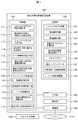
図1は、本発明の第一の実施例で適用される組立性評価システムとしての組立作業性評価計算装置100の概略全体構成図の例を示す。この組立作業性評価計算装置100は、キーボード、マウスなど、解析のために必要な設定情報の入力、メニューに選択指示、あるいはその他の指示等を入力する入力部140、評価対象モデルの表示、入力情報の表示、処理結果の表示、処理途中の経緯の表示等を行う表示部150と、3DCADデータをもとに隣接関係を取得し、組立順序、方向、動作を生成し、部品の組付け動作の評価、エルゴノミクス評価、およびその結果出力の処理などを実行する制御部110と、3DCADデータ、解析プログラム、計算条件、計算結果などを記憶する記憶部130と、ネットワーク210を介して、外部にある3DCAD装置200から3DCADデータを受信する通信部160とより構成されている。
ここで、制御部110は、CPU(中央処理装置)、ROM(リードオンリメモリ)、RAM(ランダムアクセスメモリ)を含み、および記憶部130はハードディスク装置などの外部記憶装置により構成される。入力部140はタッチパネル、専用のスイッチやセンサあるいは音声認識装置を用いてもよい。表示部150は、例えばディスプレイ、プロジェクタ、ヘッドマウントディスプレイなど画面やスクリーンに情報を表示する装置を用いる。表示部150に表示された情報を用紙に出力するプリンタ(図示しない)を組立作業性評価計算装置100に接続してもよい。
なお、これらのハード構成は、専用装置である必要はなく、パーソナルコンピュータ等の一般的なコンピュータシステムを利用することができる。
組立作業性評価計算装置100の制御部110は、3DCADモデルの情報取得手段111と、部品種別の分類と特徴形状の検出手段112と、アセンブリグラフの生成手段113と、組立順序・方向・動作の生成手段114と、ワーク座標系の算出手段115と、部品の組付け動作の評価計算手段116と、複数の作業者位置・姿勢・視点の設定手段117と、エルゴノミクス評価手段120と、組立作業性の総合評価手段118とを含む。また作業者の作業のしやすさや疲労度を評価する前記エルゴノミクス評価手段120には、視認性評価手段121と、作業姿勢・目線の評価手段122と、リーチ性評価手段123と、動線と姿勢変化の評価手段124とが含まれる。
なお、これらのハード構成は、専用装置である必要はなく、パーソナルコンピュータ等の一般的なコンピュータシステムを利用することができる。
組立作業性評価計算装置100の制御部110は、3DCADモデルの情報取得手段111と、部品種別の分類と特徴形状の検出手段112と、アセンブリグラフの生成手段113と、組立順序・方向・動作の生成手段114と、ワーク座標系の算出手段115と、部品の組付け動作の評価計算手段116と、複数の作業者位置・姿勢・視点の設定手段117と、エルゴノミクス評価手段120と、組立作業性の総合評価手段118とを含む。また作業者の作業のしやすさや疲労度を評価する前記エルゴノミクス評価手段120には、視認性評価手段121と、作業姿勢・目線の評価手段122と、リーチ性評価手段123と、動線と姿勢変化の評価手段124とが含まれる。
組立作業性評価計算装置100の記憶部130は、3DCAD装置より入手した3DCADモデル情報(評価対象モデル:組立品)およびその情報より抽出したテーブル形式の3DCADモデル情報131と、部品種別の分類と特徴形状の検出処理のために参照する部品種別情報132と、各部品の組付け動作の評価計算結果(部品組立性評点Ei)、および組立作業性の総合評価を記憶する評価結果情報133と、各手段の評価計算プログラム・計算条件を記憶する評価計算プログラム・計算条件134、組立性評価法において使用する基本要素Xのデータテーブル、および補正要素χ、および補正係数αのデータテーブルを記憶する組立性基本要素・補正要素データ135と、3DCADモデルより部品間隣接関係から生成したアセンブリグラフを記憶するアセンブリグラフ136と、組立順序・方向・動作の生成手段により生成された組立シーケンスデータを記憶する組立シーケンスデータ137と、部品の組付け方向、作業姿勢、目線、評点の各データ項目に対して、想定されるデータ値の組み合わせに対する評点をテーブル形式にて記憶する作業姿勢・目線評価情報138と、リーチ性評価処理において参照する評価関数を定義するリーチ性評価関数139の各記憶領域を備える。
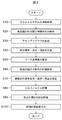
図2は、組立作業性評価計算装置100が、3DCAD装置200より入手した3DCADデータを基に組立作業性の総合評価結果を出力する処理までの手順を説明するフローチャートの例である。
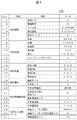
図2のステップS10の3DCADモデルの情報取得処理では、3DCAD装置200より入手して、記憶部130に記憶した3DCADモデル情報(評価対象モデル:組立品)を読み込み、組立品の部品構成、各部品の配置、モデル名や寸法、部品中心位置や部品重心位置などの部品属性、部品間の隣接関係の情報を取得して、図3に示すテーブル形式の3DCADモデル情報131を作成して記憶部130に格納する。ここで評価対象は複数の部品から構成される組立品であるアセンブリモデルとする。
図3の分類の欄の部品属性や形状特徴とは、部品ID、階層番号、モデル名、部品図番、部品タイトル、部品の体積、表面積、材質、比重、質量、最大長、重心、バウンディングボックス(部品を外包する境界となる直方体の8頂点の座標)、主慣性モーメント、慣性主軸、などが抽出される。
部品配置とは、ワールド座標系に配置されたアセンブリモデル上での各部品の位置および姿勢であり、各部品のパート座標系のX、Y、Zの3軸と部品原点から構成する。
部品配置とは、ワールド座標系に配置されたアセンブリモデル上での各部品の位置および姿勢であり、各部品のパート座標系のX、Y、Zの3軸と部品原点から構成する。
部品構成とは、3DCADモデルの部組品と部品との親子関係を示す情報であり、そのデータ項目としては、親部品ID、子部品ID、サブアセンブリを示すフラグ、対象外を示すフラグ(3DCADモデル上では非表示や抑制を示す情報)がある。
部品間隣接関係とは、アセンブリモデルをモデリングする際に設定するアセンブリ拘束情報であり、拘束要素種別、拘束要素を含む部品ID、拘束された部品ID(被拘束部品ID)、拘束面を表す拘束面法線、拘束面原点から構成する。またアセンブリ拘束情報は、モデリングする際に設計者が設定した情報だけではなく、アセンブリモデルをもとに部品と部品のクリアランス解析によって取得する方式がよい。ここでクリアランス解析の一方式としては、設定した閾値をもとにモデリングされた部品の各面からクリアランス距離内にある別のモデルを探索し、探索結果得られた隣接部品の面(平面、円筒面、円錐面など)の位置、姿勢の情報を作成する方式が挙げられる。
部品間隣接関係とは、アセンブリモデルをモデリングする際に設定するアセンブリ拘束情報であり、拘束要素種別、拘束要素を含む部品ID、拘束された部品ID(被拘束部品ID)、拘束面を表す拘束面法線、拘束面原点から構成する。またアセンブリ拘束情報は、モデリングする際に設計者が設定した情報だけではなく、アセンブリモデルをもとに部品と部品のクリアランス解析によって取得する方式がよい。ここでクリアランス解析の一方式としては、設定した閾値をもとにモデリングされた部品の各面からクリアランス距離内にある別のモデルを探索し、探索結果得られた隣接部品の面(平面、円筒面、円錐面など)の位置、姿勢の情報を作成する方式が挙げられる。
なおアセンブリ拘束とクリアランス解析の情報で得た拘束面情報は、平面の場合は、そのモデルの外側に向いた拘束面法線ベクトルと面上の点を拘束面原点に取得し、円筒面の場合は、その円筒の軸方向を拘束面法線ベクトルとして軸上の点を拘束面原点とする。
なお本図のフローチャートには、3DCADモデルのモデリング操作および解析対象としたモデルを指定する操作は省略した。
なお本図のフローチャートには、3DCADモデルのモデリング操作および解析対象としたモデルを指定する操作は省略した。
図2のステップS20の部品種別の分類と特徴形状の検出処理は、記憶部130の部品種別情報132を読み込み、指定されたモデル名の条件(例:先頭文字が指定された文字列など)や指定された部品寸法(例:指定された寸法以下など)にて、ステップS10で取得した3DCADモデル情報131に格納された各構成部品の部品種別を判定する。
図4は、記憶部130に格納されている部品種別情報132の例であり、上記のステップS20の判定で利用する。部品種別テーブル132は部品種別を引き当てるための情報として3DCADの部品属性(モデル名、部品図番、部品タイトル)と3DCADの形状特徴の判定条件の項目をもち、各行ごとの引き当て条件での部品種別名称、一致度を部品種別IDで識別する構成とする。なお図4の例では各行の引き当て条件において、空白以外の項目を条件として検索する。ここで部品図番、部品タイトルは、3DCADのパートモデルあるいはアセンブリモデルにユーザが任意に定義したテキスト情報である。また3DCADモデル名、部品タイトルなど文字列の部品属性においては、すべての文字列の完全一致だけではなく部分一致で引き当てる場合もある。そこで任意の文字を示すワイルドカード文字(*など)を含む文字列を格納する。なお文字列条件カラムを追加して、完全一致、前方一致、後方一致などの条件を定義してもよい。また形状特徴としては、寸法条件の例のほかパートモデルにおけるバウンディングボックス頂点、重心、主慣性モーメントなど3DCADモデルを計算することで取得できる質量特性を格納してもよい。また数値での判定においては、等しい、以下、より大きいなどの範囲を示す条件とし、またこれら条件のANDおよびOR条件にて設定可能とする。
図4は、記憶部130に格納されている部品種別情報132の例であり、上記のステップS20の判定で利用する。部品種別テーブル132は部品種別を引き当てるための情報として3DCADの部品属性(モデル名、部品図番、部品タイトル)と3DCADの形状特徴の判定条件の項目をもち、各行ごとの引き当て条件での部品種別名称、一致度を部品種別IDで識別する構成とする。なお図4の例では各行の引き当て条件において、空白以外の項目を条件として検索する。ここで部品図番、部品タイトルは、3DCADのパートモデルあるいはアセンブリモデルにユーザが任意に定義したテキスト情報である。また3DCADモデル名、部品タイトルなど文字列の部品属性においては、すべての文字列の完全一致だけではなく部分一致で引き当てる場合もある。そこで任意の文字を示すワイルドカード文字(*など)を含む文字列を格納する。なお文字列条件カラムを追加して、完全一致、前方一致、後方一致などの条件を定義してもよい。また形状特徴としては、寸法条件の例のほかパートモデルにおけるバウンディングボックス頂点、重心、主慣性モーメントなど3DCADモデルを計算することで取得できる質量特性を格納してもよい。また数値での判定においては、等しい、以下、より大きいなどの範囲を示す条件とし、またこれら条件のANDおよびOR条件にて設定可能とする。
図2のステップS30のアセンブリグラフの生成処理は、ステップS10で取得した3DCADモデル情報の部品間の隣接関係情報から、部品をノード(節)、隣接関係をエッジ(辺)としたグラフにて、部品間の関係を表現するデータを作成する。
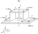
図5は、3DCADモデルの例であり、部品Aの上に部品B、部品Cがあり、部品BはネジAB2本で部品Aと締結、部品CはPONCH形状(位置あわせマーク)にて部品Aと位置あわせ、溶接されている。部品Dは部品BとネジBD2本で締結されており、また部品CとはネジCD2本で締結されている。また部品Eは部品Aの穴と部品Dの穴に挿入されている。またモデルの左下に示した座標系はワールド座標系を示す。このモデルをもとに以下、説明する。
図6は、図5に示した3DCADモデルに対し、部品間隣接関係から生成したアセンブリグラフの例である。部品をノード、部品間の隣接関係をエッジとしたグラフ表現であり、隣接関係の種類ごと(隣接方向や隣接面の種類ごと)にそれぞれエッジを生成している。また大きく平面拘束(面合致)と円筒拘束(同軸)を区別しており、図6のエッジ上には平面拘束をP、円筒拘束をCで示した。また図6では同じ名称のモデル名で組付け方向が同じで隣接関係が同じ(隣接方向や隣接面が同じ)場合は、複数の部品であっても一つのノードとして示した(例:ネジAB、ネジBD、ネジCDなど)。作成したアセンブリグラフは記憶部130に記憶する。
図2のステップS40の組立順序・方向・動作の生成では、例えば特許文献3「特開2012-14569号公報」に開示される組立シーケンス生成方法により、ステップS30で生成したアセンブリグラフ136をもとに分解可能な方向を生成し、分解方向および分解順序を生成することで、その逆変換を行い組立順序、組立方向を導出する。
図7は、組立順序・方向の生成処理までを説明するフローチャートの例である。まず3DCADの組立品モデルから分解順序・分解方向を生成し、分解順序を逆順に、分解運動ベクトルの符号を反転することにより組立順序・組立方向を生成する。
図7のステップS41は記憶部3に記憶されている3DCADモデル情報131の部品配置・部品間隣接関係データの各対象部品を内包する最小直方体の8頂点から最小直方体の6つの構成平面を構成し以下のような部品の分解順序案を生成する。
(1)構成部品のうち、最小直方体の6つの構成平面のいずれかが、鉛直方向で高い順に構成部品の順序を並べる。
(2)ユーザにより指定された方向軸に対し、最小直方体の4つの構成面が平行な部品群について、該当する4つの構成面に対し、部品間で内包関係が成立する部品群を、内側からあるいは外側からの順序に並べる。
ここで、(2)の方法において互いに内包・外包関係にあたらない2部品については、順位が決定できない。その場合、(1)により部品間の順序に序列をつけることにより、全ての部品間に序列を付けることが可能である。(1)の方法は単独で全ての部品間に序列をつけることができるが、同じ順位となる部品については、例えば、最小直方体の6つの構成平面のいずれかが左側の部品を高い順位にするなどのように条件を付加することも可能である。
(1)構成部品のうち、最小直方体の6つの構成平面のいずれかが、鉛直方向で高い順に構成部品の順序を並べる。
(2)ユーザにより指定された方向軸に対し、最小直方体の4つの構成面が平行な部品群について、該当する4つの構成面に対し、部品間で内包関係が成立する部品群を、内側からあるいは外側からの順序に並べる。
ここで、(2)の方法において互いに内包・外包関係にあたらない2部品については、順位が決定できない。その場合、(1)により部品間の順序に序列をつけることにより、全ての部品間に序列を付けることが可能である。(1)の方法は単独で全ての部品間に序列をつけることができるが、同じ順位となる部品については、例えば、最小直方体の6つの構成平面のいずれかが左側の部品を高い順位にするなどのように条件を付加することも可能である。
図7のステップS42はステップS41で生成した分解順序の順番iを初期化する。ステップS43で順番iが分解順序の最終順番に達したか否かを判断し、達していないと判断した場合(Noの場合)、ステップS44では、分解順序iの対象部品p(i)について、後述する方法により分解運動ベクトル集合v(i)を算出する。ステップS45で分解運動が生成されたか否かを判定する。近接部品との干渉で分解運動が生成されない場合(Yesの場合)、ステップS46で対象部品p(i)の順序をi+1に先送りしてステップS43に戻る。分解運動が生成された場合は(Noの場合)、ステップS47により次の順序であるi+1に処理を進めてステップS43に戻る。
次に、図7のステップS43において分解順序の最終順番まで分解運動生成を終了したと判断された場合(Yesの場合)、ステップS48に進んで分解順序を逆順にして組立順序として格納する。次にステップS49により組立順序の全ての順番iについて分解運動v(i)のベクトル符号を反転して組立運動u(i)として格納する。
次に、図7のステップS43において分解順序の最終順番まで分解運動生成を終了したと判断された場合(Yesの場合)、ステップS48に進んで分解順序を逆順にして組立順序として格納する。次にステップS49により組立順序の全ての順番iについて分解運動v(i)のベクトル符号を反転して組立運動u(i)として格納する。
ステップS44の分解運動の算出について図8に示した構造のモデルの場合について説明する。まず、ここでは分解運動算出の対象部品p(i)をaとする。図8の例では61が部品a、部品62が部品aと円筒面611で近接し、部品63が部品aと平面612で近接している。部品aと隣接するサーフェスjについて、サーフェスjの種類が円筒面及び円錐面の場合、運動ベクトルの集合は、円筒面の中心軸eiを用いて(数1)のように算出する。

サーフェスjの種類が平面の場合、運動ベクトルの集合は、部品63の平面のソリッド外向き法線と平面上の直交ベクトルから、(数2)のように算出する。

部品aに複数の隣接サーフェスが在る場合は、サーフェスごとの運動ベクトル集合の和集合を部品aの運動ベクトル集合(数3)とする。

ここで対象部品aは、近接平面により運動の動作領域が制限され、部品aは隣接平面jと干渉する可能性がある。隣接平面jの運動領域集合を以下の(数4)のように算出する。

運動ベクトル集合Maに属する運動ベクトルmiに対し、動作領域集合Daの要素ベクトルdjによる制限を加味した。


零ベクトル以外の再補正運動ベクトルを要素として、部品aの分解運動ベクトル集合V(i)とする。V(i)は(数7)で表される。

以上の処理により部品aについて近接面と干渉しない複数の組立運動ベクトルが生成され、符号を反転して(数8)で表される組立運動ベクトル集合U(i)として組立順序とともに記憶部130に組立シーケンスデータ137として格納される。

図2のステップS50のワーク座標系の算出では、ステップS40で生成した組立順序に従って、その時点での組立品がどのような姿勢で組み上がるかを決定する。これをワーク座標系と呼ぶ。作業中に重力に対して安定に静止していることをワーク姿勢のひとつの条件として、組立品の第1慣性主軸を鉛直軸とする方式とする。部品モデル個々の慣性主軸あるいは慣性テンソルは、ステップS10で取得できる。組立順序にしたがった組立品を構成する各部品の慣性テンソルを積算することにより、組立品の慣性テンソルを導出でき、その対角化により慣性主軸に変換できる。第1慣性主軸は、その軸周りの慣性モーメントが最も大きい。したがって第1慣性主軸を作業台の水平面に対して鉛直にすれば、重力に対して最も安定な姿勢となる。ただし慣性主軸には正負の符号が欠落しているので、組立て品の重心位置ベクトルから組立品のバウンディングボックスの中心位置ベクトルに向かう方向を正にとることとする。以上の手順にてワーク座標系を算出する。
図2のステップS60の部品の組付け動作の評価計算処理は、特許文献4(特開平5-114003号公報)などに開示されている組立性評価法を適用することが考えられる。
組立性評価法の概要を以下に説明する。基本減点εxは最も作業し易い組付け動作を「基準要素X0」にとって、これに与える基本減点εxを0とし、他の基本要素Xについては、上記「基準要素X0」よりも組付しにくくなるにつれて、換言すれば「生産数や生産手段、例えば使用する組立装置の種類等の条件即ち生産環境条件を揃えたときの」基本要素Xごとの組付費用Cxが上記基準要素X0の組付費用Cx0よりも大きくなるにつれてその基本減点εxが0よりも大きくなるような関数関係
(数9) εx=f1(Cx) として与えられる。
組立性評価法の概要を以下に説明する。基本減点εxは最も作業し易い組付け動作を「基準要素X0」にとって、これに与える基本減点εxを0とし、他の基本要素Xについては、上記「基準要素X0」よりも組付しにくくなるにつれて、換言すれば「生産数や生産手段、例えば使用する組立装置の種類等の条件即ち生産環境条件を揃えたときの」基本要素Xごとの組付費用Cxが上記基準要素X0の組付費用Cx0よりも大きくなるにつれてその基本減点εxが0よりも大きくなるような関数関係
(数9) εx=f1(Cx) として与えられる。
同様に図9(a)にも示すように、前記の組付費用Cxの代りに組付時間Txやこれらの指数Ixをとることもできる。すなわち、これらの関係は以下の式によって示される。
(数10) εx=f1(Cx)=f11(Tx)=f21(Ix)
つぎに図9(b)の補正要素χ、および補正係数αについて示す。補正要素χとしては部品の材質m、大きさl、仕上精度a等が挙げられ、又、この他にもいくつも考えられる。
これらの各補正要素(m,l,a…)について、その状態を1個又は複数のn個に区分し、それぞれ補正基準(m0,l0,a0…)を定義し、これらを図面等に表わされている情報(図面デ-タ)や製品、部品から抽出して指定することが出来るもので、基本要素以外に部品の組付し易さに影響を及ぼす項目である。その影響度を表わす補正指標として補正係数αが記載してあるが、この補正要素(χ)は、生産環境条件を揃えたときに、n個に区分された各状態の組付費用(Cxχn)が補正基準の組付費(Cxχ0=Cxとする)よりも大きくなるにつれてその補正係数αnが1より比例して大きくなるような関数関係として以下の数11のように与えられる。
(数11) dn=〔(cxXn)/(Cx)〕×mean
更に上記組付費用Cxχn,Cxχ0の代りに組付時間Txχn,Txχ0やこれらの指数Ixχn,Ixχ0をとることも出来ることは上記基本減点εの場合と同様である。
(数10) εx=f1(Cx)=f11(Tx)=f21(Ix)
つぎに図9(b)の補正要素χ、および補正係数αについて示す。補正要素χとしては部品の材質m、大きさl、仕上精度a等が挙げられ、又、この他にもいくつも考えられる。
これらの各補正要素(m,l,a…)について、その状態を1個又は複数のn個に区分し、それぞれ補正基準(m0,l0,a0…)を定義し、これらを図面等に表わされている情報(図面デ-タ)や製品、部品から抽出して指定することが出来るもので、基本要素以外に部品の組付し易さに影響を及ぼす項目である。その影響度を表わす補正指標として補正係数αが記載してあるが、この補正要素(χ)は、生産環境条件を揃えたときに、n個に区分された各状態の組付費用(Cxχn)が補正基準の組付費(Cxχ0=Cxとする)よりも大きくなるにつれてその補正係数αnが1より比例して大きくなるような関数関係として以下の数11のように与えられる。
(数11) dn=〔(cxXn)/(Cx)〕×mean
更に上記組付費用Cxχn,Cxχ0の代りに組付時間Txχn,Txχ0やこれらの指数Ixχn,Ixχ0をとることも出来ることは上記基本減点εの場合と同様である。
図9(a)の第1欄には組立動作を分類した基本要素Xの例を示す。第1の例10は下移動組付けであり、第2の例11は横移動組付け、第3の例12はネジ止めである。以下は省略するが、これらの基本要素は、ステップS10で抽出した3DCADモデル情報、ステップS20で判定された部品種別情報、ステップS30で生成したアセンブリグラフ、及びステップS40で生成した組立順序、組立方向情報に基づき抽出可能なもので、本例のように部品の移動、結合方法等をいくつかに区分したものである。
図9(a)の第3欄には基本要素の内容が記載してある。このような基本要素の数は数個から数十個が可能である。基本要素の数は多いほど分析・評価の精度が高くなるが一方使いにくくなる。逆に少ないほど評価プロセスは簡単になるが評価の精度が悪くなる。
図9(a)の第3欄には基本要素の内容が記載してある。このような基本要素の数は数個から数十個が可能である。基本要素の数は多いほど分析・評価の精度が高くなるが一方使いにくくなる。逆に少ないほど評価プロセスは簡単になるが評価の精度が悪くなる。
図(a)の第4欄には各基本要素に割当てられる基本減点の値の例が記載してある。本実施例では、最も組立し易い下移動を基準の基本要素にとって、これに与える基本減点を0とし、他の基本要素については、基準の基本要素より組立しにくくなるにつれて、換言すれば「生産数や生産手段、例えば自動か手動か等の条件を揃えたときの第6欄に示すような基本要素ごとのその基本要素による部品組付時間Txが大きくなるにつれてその基本減点εxが大きくなる」ようにきめてある。組付時間の代りに、組付コストをとってεxを決めても構わない。
図9(b)には補正要素の例を示す。補正要素の項目としては図示のように部品の大きさ、組付け精度等が挙げられ、又、この他にも種々可能である。これらの補正要素は3DCADモデル情報131から抽出して指定可能なもので(不足の時には必要な情報を対話入力で与えても良い)。基本要素以外に部品の組付し易さに影響を及ぼす項目を挙げ、その影響度を数値化したものであるが、生産数、生産手段によって変化しないものである。補正の仕方は、部品の組付動作ごとの基本減点Exに上述のような補正係数αを掛けて部品減点を算出する第1の方法、基準点(満点100)から部品ごとの減点の総和ΣExiを差し引いた値に補正係数αを掛ける第2の方法等、種々可能であるが、何れの場合でも、最終的に算出される部品組立性評点Eiは部品が組付け易い時、あるいは組付時間が小さい時に常に高くなるように設定されるべきものである。
部品組立性評点Eiは上記第1の方法では、
(数12) Ei=100-f11(ΣExi・αi)
また、上記第2の方法では、
(数13) Ei=100-f22{(ΣExi)・α}
と表される。
(数12) Ei=100-f11(ΣExi・αi)
また、上記第2の方法では、
(数13) Ei=100-f22{(ΣExi)・α}
と表される。
以上の結果部品組立性評点Eiとは、部品の組付けやすさの質を表わす指標となる。また、このようにして求めた部品組立性評点Eiは、基本要素ごとの組付時間Txに関連して求めた基本減点εxを部品ごとにまとめたものとして算出されるから、これは部品の組付時間Tiと所定の関数関係となる値である(Ei=f33(Ti))。
各部品の組付け動作の評価計算結果を記憶部130の評価結果情報133に記憶する。
各部品の組付け動作の評価計算結果を記憶部130の評価結果情報133に記憶する。
図2のステップS70の複数の作業者位置・姿勢・視点の生成処理では、ステップS50で算出したワーク座標系に対して、鉛直上方向であるZ軸周りに均等に複数台の仮想カメラを配置する。
図10に組立て品301に対してワーク座標系のZ軸周りに均等に複数台の仮想カメラを配置した例を示す。まずオペレータが入力部140から周方向に等配分する仮想カメラ台数N(この例ではN=6)を設定する。また併せて作業者の身長Hm、作業台の高さHwを入力する。また身長に対する腕の長さの比率、身長に対する腰の高さの比率、身長に対する頭部、目線の比率を設定する。なお身長比ではなく絶対値を設定してもよい。
まずその時点の組立品のバウンディングボックス301の上面図に対し所定距離L離れた四角枠を描く。また、2π/Nの角度でZ軸周りに均等にN台の仮想カメラを設置する位置のZ方向の軸をその四角枠上に配置する。ここで作業者の作業姿勢としては例えば立位、座位、中腰、床に寝ている状態などがあり、これらの作業姿勢では腰や頭部の位置が変化する。評価すべき視点(作業者の頭部の目の位置)の位置をオペレータが入力部140にて、立位0.9、中腰0.6、座位0.3、床上0.1と先に入力した身長比にて設定する。あるいは予め数値を登録しておき、評価すべき視点を選択する形式でもよい。図10では1つの仮想カメラの配置軸に対し、立位310、中腰311、座位312、床上313の各視点を丸印で示した。また上記は比率で設定しているが、仮想カメラの位置を絶対値で入力してもよい。また上記の組立品全体のバウンディングボックスでは本来空いている作業スペースの外側からのアプローチとなることも考えられる。そこで、設定した仮想カメラ視点を中心として作業可能な領域(例:上半身の寸法)で輪切りに区切った範囲での組立品のバウンディングボックスとし、作業可能な限り仮想カメラの視点を近づかせる計算をしてもよい。
まずその時点の組立品のバウンディングボックス301の上面図に対し所定距離L離れた四角枠を描く。また、2π/Nの角度でZ軸周りに均等にN台の仮想カメラを設置する位置のZ方向の軸をその四角枠上に配置する。ここで作業者の作業姿勢としては例えば立位、座位、中腰、床に寝ている状態などがあり、これらの作業姿勢では腰や頭部の位置が変化する。評価すべき視点(作業者の頭部の目の位置)の位置をオペレータが入力部140にて、立位0.9、中腰0.6、座位0.3、床上0.1と先に入力した身長比にて設定する。あるいは予め数値を登録しておき、評価すべき視点を選択する形式でもよい。図10では1つの仮想カメラの配置軸に対し、立位310、中腰311、座位312、床上313の各視点を丸印で示した。また上記は比率で設定しているが、仮想カメラの位置を絶対値で入力してもよい。また上記の組立品全体のバウンディングボックスでは本来空いている作業スペースの外側からのアプローチとなることも考えられる。そこで、設定した仮想カメラ視点を中心として作業可能な領域(例:上半身の寸法)で輪切りに区切った範囲での組立品のバウンディングボックスとし、作業可能な限り仮想カメラの視点を近づかせる計算をしてもよい。
図2のステップS80のエルゴノミクス評価では、ステップS70で設定した作業者視点(仮想カメラ)から想定した作業者姿勢ごとの以下のエルゴノミクス評価を行う。具体的には図1の組立作業性評価計算装置100のエルゴノミクス評価手段120に含まれる視認性評価手段121、作業姿勢・目線評価手段122、リーチ性評価手段123、動線と姿勢変化の評価手段124を順に実行する。以下、順に説明する。
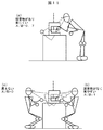
図11に視認性評価処理の例の説明図を示す。組立て順序に従って、3Dモデル上で組みつけられる部品を表示し、いま組付けられた部品モデルをハイライト表示する。このように3Dモデル上で組付け状態を表現し、設定した各仮想カメラでの各視線方向にてそれぞれの視認性を計算する。視認性の計算方法としては、例えば対象とする視線方向に設定された視野から成る2D画像上で、組付けられた状態での組み付け部品のハイライトされた部分が見えた領域の画素数Aと、その視線方向に設定された視野から成る2D画像上で組付ける部品以外を非表示とした部品単体をハイライトした領域の画素数Bを計算し、その比率A/Bを視認性の評点として計算する。この画素数の計算は例えば視線(組付ける部品のワーク座標系原点を見る方向を言う。)方向で3Dモデルから2D画像を生成する。このとき画素数Aの計算では組付け状態の表示として、評価対象の組み付けた部品をハイライト表示することで組付け部品以外の部品で視線を遮る領域によりハイライト面積が減ることとなる。なお組立て状態において他の部品を無色として生成した2D画像内の組付け部品ハイライト色の領域を算出するなどメモリ上で容易に計算できる。
例えば図11に組付け部品と作業者姿勢(視点)の例を示した。図11(a)では組付けた部品の上側を邪魔する部品があり見難い(A/B=0.7)。図11(b)では組み付ける部品がよく見える(A/B=1)。図9(c)では組み付ける部品が見えない(A/B=0)となる。
例えば図11に組付け部品と作業者姿勢(視点)の例を示した。図11(a)では組付けた部品の上側を邪魔する部品があり見難い(A/B=0.7)。図11(b)では組み付ける部品がよく見える(A/B=1)。図9(c)では組み付ける部品が見えない(A/B=0)となる。
図12(a),(b)に作業姿勢・目線評価処理の例の説明図を示す。人間工学の観点から作業姿勢と目線(視線と同じ表現になるが、本実施例では作業姿勢と目の向きから決まる首の姿勢を表す)は作業の疲労度に影響する。この作業姿勢と目線について、ステップS70で生成した作業者視点(仮想カメラ)をもとに作業者姿勢を想定し、組付け部品の位置姿勢に従って各視点での目線を推定する。このとき図12(b)に示すように、作業姿勢と目線に対する作業性の評点のテーブルを予め設定しておき、各作業姿勢と目線に対する評価を行う。
記憶部130の作業姿勢・目線評価情報138は、予め、部品の組付け方向、作業姿勢、目線、評点の各データ項目に対して、想定されるデータ値の組み合わせに対する評点をテーブル形式にて記憶する。なお図12(b)のテーブルでは立位、中腰、斜め上など離散化した情報での評価の例を示したが、腰、視点、目線をパラメータとした評点の計算式を設けてもよい。
記憶部130の作業姿勢・目線評価情報138は、予め、部品の組付け方向、作業姿勢、目線、評点の各データ項目に対して、想定されるデータ値の組み合わせに対する評点をテーブル形式にて記憶する。なお図12(b)のテーブルでは立位、中腰、斜め上など離散化した情報での評価の例を示したが、腰、視点、目線をパラメータとした評点の計算式を設けてもよい。
図13にリーチ性評価処理において参照する関数値の例を示す。作業者の腕の長さは有限であり、図10で説明した複数の仮想カメラの視点位置から想定される立ち位置によっては組付け部品にアクセスできない場合もある。そこで作業者の立ち位置と組付け部品の位置座標から距離を計算し作業者の手が届き難さ(リーチ性)を評価する。ここで例えば、図13のように容易に手が届く範囲(例:40cm以下)はリーチ性評点を1とし、手を伸ばせば届く範囲、届かない距離において評価関数を定義する。
記憶部130に予めリーチ性評価関数139を登録しておき、この関数を参照することにより、組付け部品までの距離からリーチ性を計算する。
記憶部130に予めリーチ性評価関数139を登録しておき、この関数を参照することにより、組付け部品までの距離からリーチ性を計算する。
図14に動線と姿勢変化の評価の説明図を示す。前記までの各エルゴノミクス評価手段は一つの部品組付け作業に着目した評価となっていた。ここで一つの部品組付け作業の視認性、リーチ性などが良くても、組付け完了後に次の作業に移る動きに無駄が大きい場合は、全体の作業性が劣る場合もある。そこで、組付け後に次の動作に移る移動量と作業姿勢の変化についても評価する。図14では予め設定した距離Rに部品配膳台車があると想定している。組立順序に従った組立品のバウンディングボックス400の上面図に対し、仮想カメラの視点位置から想定した作業姿勢401から、次の部品を組み付ける視点位置から想定した作業姿勢402まで、前記バウンディングボックス400の上面図の外形からL(例えば、L=20cmを想定する。)だけ離れた外周線に沿って繋げた線分の長さを次の組立までの動線として導出する。また作業姿勢の変化としては、組付け部品の組付け位置と仮想カメラの視点位置から算出した立ち位置から作業者の組付け部品にアプローチするベクトルを算出し、次の組付け作業時のベクトルとの角度変化を算出する。この動線と姿勢変化の評価により作業者の動きの無駄を把握できる。
図2のステップS90の組立作業性の総合評価では、組立作業性の総合評価手段118が上記の(1)部品の組付け動作の評価、(2)視認性評価、(3)作業姿勢・目線評価、(4)リーチ性評価、(5)動線と姿勢変化評価の各評価値について、それぞれ重み係数を掛け加算することで総合評価値として計算する。ただし、組立順序に従って、そのときの一つの組付け動作ごとに複数の仮想カメラを設定(図10の例で、周方向に等配分する仮想カメラ台数N×作業者の作業姿勢のパターン数)し、複数の作業姿勢にてエルゴノミクス評価((2)~(5))を行う。それらの処理では、先ずエルゴノミクス評価での(2)~(4)において、各組み付け作業での総合評点により上位のみに絞込む。例えば、予めオペレータにて評点閾値あるいは上位から選択する候補数を設定しておく。このように絞り込んだ各作業姿勢の候補について、組立順序に従って全ての組み合わせを生成し、その作業姿勢の動きについて(5)の評価を行い、エルゴノミクス評価としての最適解を決定する。なおこの場合も1つには決定せず、上位から複数候補までに絞り込む方式でもよい。
一方組立順序の生成においても複数案が導出される場合もある。そこでそれらについても上述の全ての処理を行う。このようにして算出したエルゴノミクス評価((2)~(5))と(1)部品の組付け動作の評価について重み係数を掛け加算することで総合評価結果値を算出する。総合評価結果は、記憶部130の評価結果情報133に記憶される。
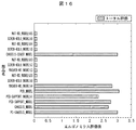
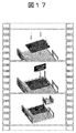
なお結果としては、各評価計算結果の出力(図15)、統合評価計算結果(図16)、最適解と決定した作業者視点から生成した組立アニメーション、作業指示図(図17)を出力する。
なお、本発明は上記した実施例に限定されるものではなく、様々な変形例が含まれる。例えば、上記した実施例は本発明を分かりやすく説明するために詳細に説明したものであり、必ずしも説明した全ての構成を備えるものに限定されるものではない。ある実施例の構成の一部を他の実施例の構成に置き換えることが可能であり、また、ある実施例の構成に他の実施例の構成を加えることも可能である。また、各実施例の構成の一部について、他の構成の追加・削除・置換をすることが可能である。
また、上記の各構成、機能、処理部、処理手段等は、それらの一部又は全部を、例えば集積回路で設計する等によりハードウェアで実現してもよい。また、上記の各構成、機能等は、プロセッサがそれぞれの機能を実現するプログラムを解釈し、実行することによりソフトウェアで実現してもよい。各機能を実現するプログラム、テーブル、ファイル等の情報は、メモリや、ハードディスク、SSD(Solid State Drive)等の記録装置、または、ICカード、SDカード、DVD等の記録媒体に置くことができる。
61 部品a、
62,63 部品、
100 組立作業性評価計算装置、
110 制御部
111 3DCADモデルの情報取得手段、
112 部品種別の分類と特徴形状の検出手段、
113 アセンブリグラフの生成手段、
114 組立順序・方向・動作の生成手段、
115 ワーク座標系の算出手段、
116 部品の組付け動作の評価計算手段、
117 複数の作業者位置・姿勢・視点の設定手段、
118 組立作業性の総合評価手段、
120 エルゴノミクス評価手段、
121 視認性評価手段、
122 作業姿勢・目線の評価手段、
123 リーチ性評価手段、
124 動線と姿勢変化の評価手段、
130 記憶部、
131 3DCADモデル情報、
132 部品種別情報、
133 評価結果情報、
134 評価計算プログラム・計算条件、
135 組立性基本要素・補正要素データ、
136 アセンブリグラフ、
137 組立シーケンスデータ、
138 作業姿勢・目線評価情報、
139 リーチ性評価関数、
140 入力部、
150 表示部、
160 通信部、
200 3DCAD装置、
210 ネットワーク、
301 被組付け品、
302 組付け対象部品、
303 組付け位置、
310,320,330,340,350,360 周方向に等配分する仮想カメラの視点、
311 中腰の視点、
312 座位の視点、
313 床上の視点、
400 組立品のバウンディングボックス、
401 仮想カメラの視点位置から想定した作業姿勢、
402 次の部品を組み付ける視点位置から想定した作業姿勢、
611 円筒面、
612 平面。
62,63 部品、
100 組立作業性評価計算装置、
110 制御部
111 3DCADモデルの情報取得手段、
112 部品種別の分類と特徴形状の検出手段、
113 アセンブリグラフの生成手段、
114 組立順序・方向・動作の生成手段、
115 ワーク座標系の算出手段、
116 部品の組付け動作の評価計算手段、
117 複数の作業者位置・姿勢・視点の設定手段、
118 組立作業性の総合評価手段、
120 エルゴノミクス評価手段、
121 視認性評価手段、
122 作業姿勢・目線の評価手段、
123 リーチ性評価手段、
124 動線と姿勢変化の評価手段、
130 記憶部、
131 3DCADモデル情報、
132 部品種別情報、
133 評価結果情報、
134 評価計算プログラム・計算条件、
135 組立性基本要素・補正要素データ、
136 アセンブリグラフ、
137 組立シーケンスデータ、
138 作業姿勢・目線評価情報、
139 リーチ性評価関数、
140 入力部、
150 表示部、
160 通信部、
200 3DCAD装置、
210 ネットワーク、
301 被組付け品、
302 組付け対象部品、
303 組付け位置、
310,320,330,340,350,360 周方向に等配分する仮想カメラの視点、
311 中腰の視点、
312 座位の視点、
313 床上の視点、
400 組立品のバウンディングボックス、
401 仮想カメラの視点位置から想定した作業姿勢、
402 次の部品を組み付ける視点位置から想定した作業姿勢、
611 円筒面、
612 平面。
Claims (8)
- 組立品を構成する複数の部品を順次組み立てる組立作業の組立性、作業性を評価する組立作業性評価計算装置であって、
複数の部品のそれぞれの部品属性と部品配置と他の部品との隣接関係の情報をCADから取得した3DCADモデルから抽出する情報取得手段と、
取得した3DCADモデルの情報から部品種別を分類する部品種別の分類と特徴形状の検出手段と、
3DCADモデル情報の部品間の隣接関係情報から、部品をノード、隣接関係をエッジとしたグラフにて、部品間の関係を表現する手段と、
前記アセンブリグラフをもとに分解可能な方向を生成し、分解方向および分解順序を生成することで、その逆変換を行い組立順序、組立方向を導出する手段と、
部品の組付動作ごとの基本減点Exに補正係数αを掛けて部品減点を算出し、基準点(満点100)から部品ごとの減点の総和を差し引いて部品の組付けやすさの質を表わす指標を算出する手段と、
組立順序に従って複数の仮想的な作業者位置・姿勢・視点を生成する手段と、
生成した作業者位置・姿勢・視点での作業性を評価する手段と、
前記部品の組付けやすさの指標の評価値と組立作業性の総合評価値を算出し、その結果を出力する総合評価手段と、を備えたことを特徴とする組立作業性評価計算装置。 - 前記作業性を評価する手段は、設定した複数の仮想的な作業者位置・姿勢・視点のそれぞれの組合せにおいて、
その視線から見た組付け部品の見易さを評価する視認性評価手段と、
作業者の姿勢と目線の方向から作業者疲労度を評価する作業姿勢・目線の評価手段と、
組付ける部品までの距離を評価するリーチ性評価手段と、
次の動作への距離や作業者の姿勢変化を評価する動線と姿勢変化の評価手段の少なくとも一つを含んでいることを特徴とする請求項1に記載の組立作業性評価計算装置。 - 前記視認性評価手段は、設定した仮想的な作業者位置・姿勢・視点において、組立順序に従った部品組付けの際に見える組付け部品の画像の領域と、他の部品がなく組付け部品単体で同じ位置・方向から見た画像の領域との比較から評点を算出することを特徴とする請求項2に記載の組立作業性評価計算装置。
- 前記作業姿勢・目線の評価手段、およびリーチ性評価手段は、予め作業の姿勢と目線、および部品との距離に対する評点の関係テーブル、または関係式を記憶部に登録しておき、該関係テーブル、または関係式に基づき評点を算出することを特徴とする請求項2に記載の組立作業性評価計算装置。
- 前記動線と姿勢変化の評価手段は,組立順序にしたがって変化する作業者位置・姿勢について、次の組立作業までの動線は組立品の3DCADモデルのバウンディングボックスを基に所定距離離れた周囲上にその経路長を計算し、その姿勢変化は作業位置から組付け部品までのベクトルの角度変化から算出することを特徴とする請求項2に記載の組立作業性評価計算装置。
- 前記組立順序、組立方向を導出する手段により生成した複数の部品の組立動作、および前記部品の組付けやすさの指標の評価値と組立作業性の総合評価値を算出した際に選定した作業者の位置・姿勢・視点に基づいて、組立アニメーションを生成する手段を更に備えたことを特徴とする請求項1に記載の組立作業性評価計算装置。
- 組立品を構成する複数の部品を順次組み立てる組立作業の組立性、作業性を評価する組立作業性評価方法であって、
複数の部品のそれぞれの部品属性と部品配置と他の部品との隣接関係の情報をCADから取得した3DCADモデルから抽出する工程と、
取得した3DCADモデルの情報から部品種別を分類し、および特徴形状を検出する工程と、
3DCADモデル情報の部品間の隣接関係情報から、部品をノード、隣接関係をエッジとしたグラフにて、部品間の関係を表現する工程と、
前記アセンブリグラフをもとに分解可能な方向を生成し、分解方向および分解順序を生成することで、その逆変換を行い組立順序、組立方向を導出する工程と、
部品の組付動作ごとの基本減点Exに補正係数αを掛けて部品減点を算出し、基準点(満点100)から部品ごとの減点の総和を差し引いて部品の組付けやすさの質を表わす指標を算出する工程と、
組立順序に従って複数の仮想的な作業者位置・姿勢・視点を生成する工程と、
生成した作業者位置・姿勢・視点での作業性を評価する工程と、
前記部品の組付けやすさの指標の評価値と組立作業性の総合評価値を算出し、その結果を出力する総合評価工程と、を有することを特徴とする組立作業性評価方法。 - 前記作業性を評価する工程は、設定した複数の仮想的な作業者位置・姿勢・視点のそれぞれの組合せにおいて、
その視線から見た組付け部品の見易さを評価する視認性評価工程と、
作業者の姿勢と目線の方向から作業者疲労度を評価する作業姿勢・目線の評価工程と、
組付ける部品までの距離を評価するリーチ性評価工程と、
次の動作への距離や作業者の姿勢変化を評価する動線と姿勢変化の評価工程の少なくとも一つを含んでいることを特徴とする請求項7に記載の組立作業性評価方法。
Priority Applications (1)
| Application Number | Priority Date | Filing Date | Title |
|---|---|---|---|
| US14/646,038 US10324452B2 (en) | 2012-11-21 | 2013-10-31 | Assembly workability evaluation calculation device and assembly workability evaluation method |
Applications Claiming Priority (2)
| Application Number | Priority Date | Filing Date | Title |
|---|---|---|---|
| JP2012-255303 | 2012-11-21 | ||
| JP2012255303A JP5833998B2 (ja) | 2012-11-21 | 2012-11-21 | 組立作業性評価計算装置、および組立作業性評価方法 |
Publications (1)
| Publication Number | Publication Date |
|---|---|
| WO2014080733A1 true WO2014080733A1 (ja) | 2014-05-30 |
Family
ID=50775919
Family Applications (1)
| Application Number | Title | Priority Date | Filing Date |
|---|---|---|---|
| PCT/JP2013/079500 Ceased WO2014080733A1 (ja) | 2012-11-21 | 2013-10-31 | 組立作業性評価計算装置、および組立作業性評価方法 |
Country Status (3)
| Country | Link |
|---|---|
| US (1) | US10324452B2 (ja) |
| JP (1) | JP5833998B2 (ja) |
| WO (1) | WO2014080733A1 (ja) |
Cited By (5)
| Publication number | Priority date | Publication date | Assignee | Title |
|---|---|---|---|---|
| CN106292541A (zh) * | 2016-08-15 | 2017-01-04 | 汤晟 | 外来检测数据与检测特征的关联方法 |
| WO2022123752A1 (ja) * | 2020-12-10 | 2022-06-16 | 日本電気株式会社 | 画像処理装置、画像処理方法、及びコンピュータ読み取り可能な記録媒体 |
| US20230021714A1 (en) * | 2021-07-26 | 2023-01-26 | Panasonic Intellectual Property Management Co., Ltd. | Dismantling procedure selecting apparatus, dismantling procedure selecting method, and dismantling apparatus |
| US11580156B2 (en) | 2019-11-28 | 2023-02-14 | Mitsubishi Electric Corporation | Workpiece image search apparatus and workpiece image search method |
| JP7622484B2 (ja) | 2021-03-11 | 2025-01-28 | 富士フイルムビジネスイノベーション株式会社 | 設計支援装置、設計支援システム、及び設計支援プログラム |
Families Citing this family (25)
| Publication number | Priority date | Publication date | Assignee | Title |
|---|---|---|---|---|
| US9053562B1 (en) | 2010-06-24 | 2015-06-09 | Gregory S. Rabin | Two dimensional to three dimensional moving image converter |
| US10127332B2 (en) * | 2013-12-23 | 2018-11-13 | Dassault Systemes Solidworks Corporation | Automatic motion of a computer-aided design model |
| JP6357983B2 (ja) * | 2014-09-02 | 2018-07-18 | 日産自動車株式会社 | ホースの挿入性評価方法および挿入性評価システム |
| TWI521387B (zh) * | 2014-12-25 | 2016-02-11 | 國立臺灣大學 | 三維空間中之可重置式虛擬觸控板 |
| JP6604039B2 (ja) * | 2015-06-08 | 2019-11-13 | 富士通株式会社 | 設計プログラム、情報処理装置、および設計方法 |
| US10860752B2 (en) | 2015-08-25 | 2020-12-08 | Dassault Systémes Americas Corp. | Method and system for vision measure for digital human models |
| US10401804B1 (en) * | 2015-12-29 | 2019-09-03 | Dassault Systemes Solidworks Corporation | Mate controller |
| US9836673B2 (en) * | 2015-12-30 | 2017-12-05 | International Business Machines Corporation | System, method and computer program product for training a three dimensional object indentification system and identifying three dimensional objects using semantic segments |
| JP6504072B2 (ja) * | 2016-02-15 | 2019-04-24 | オムロン株式会社 | 作業領域推定装置、制御装置、制御システム、作業領域推定方法およびプログラム |
| KR101764120B1 (ko) | 2016-11-21 | 2017-08-14 | 한국과학기술정보연구원 | 3d 모델링 기반 삽입력과 이탈력 해석 방법 및 그 장치 |
| CN110100265B (zh) * | 2016-12-19 | 2023-06-30 | 惠普发展公司,有限责任合伙企业 | 3d制造部件的布置确定 |
| US11262175B2 (en) * | 2017-02-05 | 2022-03-01 | Progressivehealth Companies, Llc | Method and apparatus for measuring an individual's abtility to perform a varying range of barrier reaches |
| US12114970B2 (en) | 2017-02-05 | 2024-10-15 | ProgressiveHealthCompanies, LLC | Method and apparatus for simulating, measuring and recording a subject's ability to perform a varying range of barrier reaches |
| US10963596B1 (en) * | 2017-09-12 | 2021-03-30 | Atlatl Software, Inc. | Systems and methods for CAD automation |
| JP6805206B2 (ja) * | 2018-05-22 | 2020-12-23 | 日本電信電話株式会社 | 検索ワードサジェスト装置、表現情報の作成方法、および、表現情報の作成プログラム |
| JP6952650B2 (ja) * | 2018-06-07 | 2021-10-20 | 株式会社日立製作所 | 作業指示生成装置および作業指示生成方法 |
| CN109262259B (zh) * | 2018-10-29 | 2023-10-10 | 富加宜电子(南通)有限公司 | 一种sd卡自动组装及测试设备 |
| JP7188057B2 (ja) * | 2018-12-21 | 2022-12-13 | 富士通株式会社 | 情報処理装置、判定プログラム及び判定方法 |
| JP7422632B2 (ja) * | 2020-09-07 | 2024-01-26 | 株式会社日立製作所 | 計画装置、計画方法、および計画プログラム |
| US11475173B2 (en) * | 2020-12-31 | 2022-10-18 | Dassault Systémes SolidWorks Corporation | Method for replicating a component mating in an assembly |
| CN113297734B (zh) * | 2021-05-21 | 2024-03-29 | 南京邮电大学 | 一种基于可视化锥的受限空间内装配工艺仿真评价方法 |
| JP7297035B2 (ja) * | 2021-11-29 | 2023-06-23 | 株式会社ミスミ | 見積システム、見積プログラム、及び見積システムの制御方法 |
| JP7670634B2 (ja) * | 2022-01-13 | 2025-04-30 | 株式会社日立製作所 | 設計支援システム、設計支援方法および設計支援プログラム |
| US12554243B2 (en) * | 2022-12-12 | 2026-02-17 | Rivian Ip Holdings, Llc | Model for a manufacturing process |
| JPWO2025169443A1 (ja) | 2024-02-09 | 2025-08-14 |
Citations (7)
| Publication number | Priority date | Publication date | Assignee | Title |
|---|---|---|---|---|
| JPH0773157A (ja) * | 1993-06-15 | 1995-03-17 | Ishikawajima Harima Heavy Ind Co Ltd | 大型構造物における溶接作業性の評価方法 |
| JPH08287127A (ja) * | 1995-04-14 | 1996-11-01 | Toshiba Corp | 製品組立性評価装置 |
| JPH10240324A (ja) * | 1997-02-27 | 1998-09-11 | Toshiba Corp | 組立順序抽出方法及びその装置 |
| JP2002144171A (ja) * | 2000-11-07 | 2002-05-21 | Mitsubishi Heavy Ind Ltd | 組立性の定量評価システム及び自動シミュレーションシステム |
| JP2004029958A (ja) * | 2002-06-21 | 2004-01-29 | Toshiba Corp | 作業性評価方法及びその装置 |
| JP2008046924A (ja) * | 2006-08-17 | 2008-02-28 | Hitachi Ltd | 組立物情報生成装置 |
| JP2009122726A (ja) * | 2007-11-12 | 2009-06-04 | Hitachi Ltd | 作業性解析装置 |
Family Cites Families (11)
| Publication number | Priority date | Publication date | Assignee | Title |
|---|---|---|---|---|
| US5717598A (en) * | 1990-02-14 | 1998-02-10 | Hitachi, Ltd. | Automatic manufacturability evaluation method and system |
| JP3024350B2 (ja) | 1991-04-04 | 2000-03-21 | 株式会社日立製作所 | 製造性自動評価方法およびシステム |
| JP3391648B2 (ja) | 1997-02-27 | 2003-03-31 | 富士通株式会社 | 機器操作性評価支援装置 |
| JP2002251212A (ja) * | 2001-02-21 | 2002-09-06 | Toyota Motor Corp | 品質管理方法、同システム、および同プログラムを記録した記録媒体 |
| JP4136673B2 (ja) | 2003-01-10 | 2008-08-20 | 株式会社リコー | 機器安全性検証装置、機器安全性検証方法、および記憶媒体 |
| JP2006346840A (ja) * | 2005-06-20 | 2006-12-28 | Sharp Corp | 情報処理装置 |
| JP4745831B2 (ja) * | 2006-01-06 | 2011-08-10 | 富士通株式会社 | 機器操作性評価装置、機器操作性評価方法及び機器操作性評価プログラム |
| JP4629594B2 (ja) * | 2006-02-20 | 2011-02-09 | 株式会社日立製作所 | モジュール評価方法及び装置 |
| JP5686538B2 (ja) | 2010-07-02 | 2015-03-18 | 株式会社日立製作所 | 組立シーケンス生成システム、プログラム及び方法 |
| JP5639907B2 (ja) * | 2011-01-25 | 2014-12-10 | 株式会社日立製作所 | 設計支援装置、方法およびプログラム |
| US8738180B2 (en) * | 2011-12-14 | 2014-05-27 | GM Global Technology Operations LLC | Robot control during an e-stop event |
-
2012
- 2012-11-21 JP JP2012255303A patent/JP5833998B2/ja not_active Expired - Fee Related
-
2013
- 2013-10-31 WO PCT/JP2013/079500 patent/WO2014080733A1/ja not_active Ceased
- 2013-10-31 US US14/646,038 patent/US10324452B2/en active Active
Patent Citations (7)
| Publication number | Priority date | Publication date | Assignee | Title |
|---|---|---|---|---|
| JPH0773157A (ja) * | 1993-06-15 | 1995-03-17 | Ishikawajima Harima Heavy Ind Co Ltd | 大型構造物における溶接作業性の評価方法 |
| JPH08287127A (ja) * | 1995-04-14 | 1996-11-01 | Toshiba Corp | 製品組立性評価装置 |
| JPH10240324A (ja) * | 1997-02-27 | 1998-09-11 | Toshiba Corp | 組立順序抽出方法及びその装置 |
| JP2002144171A (ja) * | 2000-11-07 | 2002-05-21 | Mitsubishi Heavy Ind Ltd | 組立性の定量評価システム及び自動シミュレーションシステム |
| JP2004029958A (ja) * | 2002-06-21 | 2004-01-29 | Toshiba Corp | 作業性評価方法及びその装置 |
| JP2008046924A (ja) * | 2006-08-17 | 2008-02-28 | Hitachi Ltd | 組立物情報生成装置 |
| JP2009122726A (ja) * | 2007-11-12 | 2009-06-04 | Hitachi Ltd | 作業性解析装置 |
Cited By (10)
| Publication number | Priority date | Publication date | Assignee | Title |
|---|---|---|---|---|
| CN106292541A (zh) * | 2016-08-15 | 2017-01-04 | 汤晟 | 外来检测数据与检测特征的关联方法 |
| CN106292541B (zh) * | 2016-08-15 | 2018-10-16 | 汤晟 | 外来检测数据与检测特征的关联方法 |
| US11580156B2 (en) | 2019-11-28 | 2023-02-14 | Mitsubishi Electric Corporation | Workpiece image search apparatus and workpiece image search method |
| WO2022123752A1 (ja) * | 2020-12-10 | 2022-06-16 | 日本電気株式会社 | 画像処理装置、画像処理方法、及びコンピュータ読み取り可能な記録媒体 |
| JP7473012B2 (ja) | 2020-12-10 | 2024-04-23 | 日本電気株式会社 | 画像処理装置、画像処理方法、及びプログラム |
| US12499642B2 (en) | 2020-12-10 | 2025-12-16 | Nec Corporation | Image processing apparatus, image processing method, and computer-readable recording medium |
| JP7622484B2 (ja) | 2021-03-11 | 2025-01-28 | 富士フイルムビジネスイノベーション株式会社 | 設計支援装置、設計支援システム、及び設計支援プログラム |
| US20230021714A1 (en) * | 2021-07-26 | 2023-01-26 | Panasonic Intellectual Property Management Co., Ltd. | Dismantling procedure selecting apparatus, dismantling procedure selecting method, and dismantling apparatus |
| CN115673702A (zh) * | 2021-07-26 | 2023-02-03 | 松下知识产权经营株式会社 | 解体步骤选择装置及解体步骤选择方法及解体装置 |
| US12243222B2 (en) * | 2021-07-26 | 2025-03-04 | Panasonic Intellectual Property Management Co., Ltd. | Dismantling procedure selecting apparatus, dismantling procedure selecting method, and dismantling apparatus |
Also Published As
| Publication number | Publication date |
|---|---|
| JP5833998B2 (ja) | 2015-12-16 |
| US20150293525A1 (en) | 2015-10-15 |
| JP2014100773A (ja) | 2014-06-05 |
| US10324452B2 (en) | 2019-06-18 |
Similar Documents
| Publication | Publication Date | Title |
|---|---|---|
| JP5833998B2 (ja) | 組立作業性評価計算装置、および組立作業性評価方法 | |
| US9956655B2 (en) | Apparatus for generating assembly sequence and method for generating assembly sequence | |
| Wang et al. | A comprehensive survey of augmented reality assembly research | |
| JP5639907B2 (ja) | 設計支援装置、方法およびプログラム | |
| Wang et al. | Assembly planning and evaluation in an augmented reality environment | |
| Re et al. | Impact of monitor-based augmented reality for on-site industrial manual operations | |
| KR102068197B1 (ko) | 산업 오브젝트들의 멀티-핸드 파지들을 위한 핸드 포지션들을 예측하기 위한 방법들 및 시스템 | |
| Peruzzini et al. | Human-centred design of ergonomic workstations on interactive digital mock-ups | |
| Qiu et al. | Virtual human hybrid control in virtual assembly and maintenance simulation | |
| Techasarntikul et al. | Guidance and visualization of optimized packing solutions | |
| JP2015153237A (ja) | 組立順序生成装置および組立順序生成方法 | |
| JP2018180693A (ja) | 作業指示生成装置および作業指示生成方法 | |
| CN112486319B (zh) | 基于触觉渲染设备的vr交互方法、装置、设备及介质 | |
| Guo et al. | A quantitative assessment method for the space design of products based on ergonomics and virtual simulation | |
| Akdaş et al. | Virtual reality in product design: Researches between 1997 and 2021 | |
| Arroyave-Tobón et al. | Ergonomic analysis in conceptual design stage using a gesture-based modelling tool | |
| US20140088931A1 (en) | Computer product, verification support method, and verification support apparatus | |
| Plinta et al. | Ergonomics analysis in the context of a digital factory | |
| Behar et al. | Dynamic minkowski sums under scaling | |
| Mesuda et al. | Virtual manipulations for draping | |
| da Silva et al. | Virtual Reality and Digital Human Modeling for the Physical Ergonomic Analysis in Product Development in Industry: A Systematic Review | |
| Sang | Development and evaluation of a temporary placement and conveyance operation simulation system using augmented reality | |
| WO2012111104A1 (ja) | 解析用モデル作成支援装置及び解析用モデル作成支援プログラム | |
| EP3877958A1 (en) | A system for determining visually relevant design differences between 3d models | |
| Jonek et al. | Constraints for motion generation in work planning with digital human simulations |
Legal Events
| Date | Code | Title | Description |
|---|---|---|---|
| 121 | Ep: the epo has been informed by wipo that ep was designated in this application |
Ref document number: 13856471 Country of ref document: EP Kind code of ref document: A1 |
|
| WWE | Wipo information: entry into national phase |
Ref document number: 14646038 Country of ref document: US |
|
| NENP | Non-entry into the national phase |
Ref country code: DE |
|
| 122 | Ep: pct application non-entry in european phase |
Ref document number: 13856471 Country of ref document: EP Kind code of ref document: A1 |