WO2014080581A1 - 注出部材 - Google Patents
注出部材 Download PDFInfo
- Publication number
- WO2014080581A1 WO2014080581A1 PCT/JP2013/006544 JP2013006544W WO2014080581A1 WO 2014080581 A1 WO2014080581 A1 WO 2014080581A1 JP 2013006544 W JP2013006544 W JP 2013006544W WO 2014080581 A1 WO2014080581 A1 WO 2014080581A1
- Authority
- WO
- WIPO (PCT)
- Prior art keywords
- protrusion
- cap
- pouring
- central axis
- unsealing
- Prior art date
- Legal status (The legal status is an assumption and is not a legal conclusion. Google has not performed a legal analysis and makes no representation as to the accuracy of the status listed.)
- Ceased
Links
Images




Classifications
-
- B—PERFORMING OPERATIONS; TRANSPORTING
- B65—CONVEYING; PACKING; STORING; HANDLING THIN OR FILAMENTARY MATERIAL
- B65D—CONTAINERS FOR STORAGE OR TRANSPORT OF ARTICLES OR MATERIALS, e.g. BAGS, BARRELS, BOTTLES, BOXES, CANS, CARTONS, CRATES, DRUMS, JARS, TANKS, HOPPERS, FORWARDING CONTAINERS; ACCESSORIES, CLOSURES, OR FITTINGS THEREFOR; PACKAGING ELEMENTS; PACKAGES
- B65D75/00—Packages comprising articles or materials partially or wholly enclosed in strips, sheets, blanks, tubes or webs of flexible sheet material, e.g. in folded wrappers
- B65D75/52—Details
- B65D75/58—Opening or contents-removing devices added or incorporated during package manufacture
- B65D75/5861—Spouts
- B65D75/5872—Non-integral spouts
- B65D75/5883—Non-integral spouts connected to the package at the sealed junction of two package walls
Definitions
- the present invention relates to a pouring member attached to a container in which fluid contents are sealed and filled to form a pouring outlet for the contents, and in particular, a pouring member provided with an opening mechanism that can be opened by rotation of an opening cap. About.
- a bag-like container formed by making a soft packaging material such as a resin film is known as a container in which a fluid content is hermetically filled.
- a container in which a fluid content is hermetically filled.
- this type of bag-like container is often used as a container for sealing and filling enteral nutrients, liquid foods, liquid medicines, etc., and these contents are poured out to patients.
- a nozzle-like dispensing member is used, and an example thereof is shown in Patent Document 1.
- the pouring member (container cap device) disclosed in Patent Document 1 rotates the opening cap with respect to the pouring cylinder, thereby twisting the stopper plug engaged with the opening cap and pouring. It can be opened hygienically without touching the outlet.
- the stopper plug is twisted off by rotating the opening cap or the like, for example, at the time of transfer or sealing and filling the contents.
- the contents may leak out. For this reason, it is desirable to prevent erroneous opening due to unnecessary rotation of the opening cap or pulling it out except during use.
- This invention is made
- An object of the present invention is to provide a dispensing member that can more reliably prevent misopening due to.
- the pouring member according to the present invention includes a pouring member main body and an opening cap that is concentrically mounted on the pouring member main body, and the pouring member main body rises in a cylindrical shape from a base portion.
- a sealing portion is formed on the distal end side of the dispensing tube portion via a thin portion, and the opening cap engaged with the sealing portion is rotated around a central axis.
- the pouring member in which the sealing portion is twisted off at the thin wall portion to open the pouring tube portion, and is an engagement protrusion on the inner peripheral surface on the opening end side of the unsealing cap. Is formed, and a three-way projection that is engaged with the engagement projection and surrounds the upper and left and right sides of the engagement projection is formed on the base side of the extraction tube portion. .
- the present invention by engaging the engagement protrusion formed on the unsealing cap side with the three-way protrusion surrounding the upper and left and right sides of the engagement protrusion formed on the extraction member main body side. Further, it is possible to more reliably prevent erroneous opening due to unnecessary rotation of the unsealing cap or pulling it out except during use.
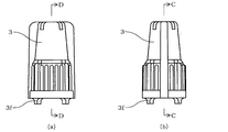
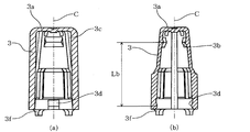
- FIG. 5A is a cross-sectional view of the unsealing cap, and the cross section shown in FIG. 5A corresponds to the CC cross section of FIG. 5B including the central axis C, and the cross section shown in FIG. This corresponds to the DD section of (a).
- FIG. 5A shows the state which removed the unsealing cap from the extraction member main body. The figure which shows the state which the three-way protrusion and the engagement protrusion engaged, and the state which the engagement protrusion which the engagement with the three-way protrusion was released contact
- the pouring member 1 in this embodiment includes a pouring member body 2 and an opening cap 3 attached to the pouring member body 2.
- These members provided in the dispensing member 1 can be manufactured by a molding means such as injection molding using a thermoplastic resin such as a polyolefin resin such as polypropylene or polyethylene.
- the pouring member main body 2 has a pouring cylinder portion 22 that rises in a cylindrical shape from the base portion 23, and a horizontal portion is disposed at the boundary portion between the pouring tube portion 22 and the base portion 23.
- a flange portion 2c is formed so as to protrude from the surface.
- the sealing part 21 is formed in the front end side of the pouring cylinder part 22 via the thin part 21a, and the pouring part 22 is unsealed by twisting off the sealing part 21 by the thin part 21a. I can do it.
- the unsealing due to the unsealing of the sealing portion 21 due to the unsealing of the unsealing cap 3 mounted on the dispensing member main body 2 unnecessarily rotating or being pulled out is prevented.
- a three-way projection 5 is formed on the base 23 side of the dispensing cylinder 22.
- the boat-shaped part 24 located in the downward direction with respect to the base 23 is formed in the extraction
- the boat-shaped part 24 formed in the extraction member main body 2 is used when, for example, the extraction member 1 is attached to a container such as a pouch formed by making a soft packaging material such as a resin film as an outlet for contents. It is a part to be a welded portion, and includes three welded substrates 24 a that extend horizontally to the left and right, and a positioning substrate 24 b that is positioned at a boundary portion with the base 23. Thereby, when the pouring member 1 is attached to the pouch as a pouring outlet for the contents, as shown in FIG. 1 by an alternate long and two short dashes line, the positioning substrate 24b is placed on the edge of the soft packaging material forming the pouch. The soft wrapping material is welded to the side surface of the welding substrate 24a while positioning the same.
- the unsealing cap 3 is a cylindrical member provided with a top plate 3a.
- the unsealing cap 3 is engaged with the dispensing member main body 2 at two locations, a sealing portion 21 formed on the distal end side of the dispensing tube portion 22 and a three-way projection 5 formed on the base portion 23 side. It is mounted by a stopper so as to fit together, and covers the periphery of the extraction tube portion 22.
- the sealing portion 21 has a protruding portion 21b that protrudes in a bowl shape along its periphery.
- an engagement rib 3b that engages with the protruding portion 21b may be formed on the inner peripheral surface of the unsealing cap 3.
- the opening cap 3 on the dispensing member main body 2 When opening the opening cap 3 on the dispensing member main body 2, the opening cap 3 is tilted or the opening cap 3 is pressed more than necessary toward the dispensing member main body 2 to seal the opening member 3.
- the thin portion 21a For the purpose of preventing the thin portion 21a from being broken and erroneously opened due to the stop portion 21 being inclined or the like, as shown in FIGS. 5 and 6, it is suspended from the end surface on the opening end side. And the protrusion 3f contact
- FIG. 7 is explanatory drawing which shows the state which removed the opening cap 3 from the extraction cylinder part main body 2, and the opening cap 3 has shown the cross section which abbreviate
- a pair of protruding pieces 21c protruding in the radial direction is formed on the sealing portion 21.
- a locking groove 3c for locking the protruding piece 21c may be formed on the inner peripheral surface of the opening cap 3.
- the sealing portion 21 can be twisted to open the dispensing cylinder portion 22, and the contents can be dispensed from the tip of the opened dispensing cylinder portion 22. That is, for example, the user can hold the base 23 side of the pouring member body 2 with one hand and rotate the unsealing cap 3 with the other hand without sanitizing the pouring cylinder 22.
- the sealing portion 21 can be twisted off.
- the unsealing due to the unsealing of the sealing portion 21 due to the unsealing of the unsealing cap 3 mounted on the dispensing member main body 2 unnecessarily rotating or being pulled out is prevented.
- the three-way protruding portion 5 formed on the base 23 side of the dispensing tube portion 22 and the opening cap 3 The unsealing cap 3 is attached to the dispensing member main body 2 by engagement with the engagement protrusion 3d formed on the inner peripheral surface on the opening end side.
- the three-way projection 5 formed on the dispensing cylinder portion 22 of the dispensing member main body 2 surrounds the engagement projection 3d on the side of the opening cap 3 that engages with this, and the three sides on the left and right, and the opening cap 3 is not attached.
- the beam-like protrusion 5a extending along the peripheral surface of the extraction tube portion 22 and the both ends of the beam-like protrusion are poured out so that it can be prevented from being rotated or pulled out as necessary. It is formed in a gate shape composed of a pair of left and right columnar protrusions 5 b formed so as to hang down along the peripheral surface of the cylindrical portion 22.
- the engagement protrusion 3d formed on the unsealing cap 3 side is formed into a beam shape of the three-way protrusion 5 formed on the pouring member main body 2 side.
- the protrusion 5a gets over and engages with each other, and the engagement protrusion 3d abuts against the beam-like protrusion 5a, thereby restricting the upward movement of the unsealing cap 3, and the engagement protrusion 3d abuts against the columnar protrusion 5b. This restricts the left-right movement (rotation) of the unsealing cap 3.
- the upper surface side of the beam-like protrusion 5a has a central axis C so that the engaging protrusion 3d can easily get over the beam-like protrusion 5a of the three-way protrusion 5. It is preferable to form it so as to be inclined linearly or curvedly in a cross section including
- the engaging ribs 3 b formed on the unsealing cap 3 get over the protruding portion 21 b formed on the sealing portion 21 and engage with each other.
- the opening cap 3 and the sealing portion 21 are engaged as described above.
- the impact due to the stopper is excessively applied to the sealing portion 21, the thin wall is formed. It is conceivable that the portion 21a is broken and erroneously opened.
- the angle ⁇ formed between the tangent L1 at the upper end of the protrusion 21b in the cross section including the central axis C and the central axis C is a three-way protrusion in the cross section including the central axis C.
- the angle ⁇ formed by the tangent L2 at the upper end of the beam-like protrusion 5a of the portion 5 and the central axis C is made smaller than the angle ⁇ formed by the tangent L2 at the upper end of the beam-like protrusion 5a of the portion 5 and the central axis C. That is, by making the angle ⁇ smaller than the angle ⁇ , the resistance when the engaging rib 3b formed on the unsealing cap 3 engages the protruding portion 21b formed on the sealing portion 21 is reduced. Thus, the impact on the sealing portion 21 is reduced, so that erroneous opening can be further prevented.
- the timing at which the engaging rib 3b formed on the unsealing cap 3 gets over the protruding portion 21b formed on the sealing portion 21 and the engaging protrusion 3d formed on the unsealing cap 3 are the beam shape of the three-way protruding portion 5.
- the distance between the upper end of the protrusion 21b along the central axis C and the upper end of the beam-like protrusion 5a of the three-way protrusion 5 is La1 (FIG.
- the distance along the central axis C between the most protruding portion of the engaging rib 3b formed on the inner peripheral surface of the unsealing cap 3 and the most protruding portion of the engaging protruding portion 3d is Lb (FIG. 6B). ))), It is preferable that the relationship Lb ⁇ La1 ⁇ 0.5 mm holds.
- the distance between the lower end of the protrusion 21b along the central axis C and the lower end of the beam-like protrusion 5a of the three-way protrusion 5 is La2 (see FIG. 2B)
- the distance between the distance Lb It is preferable that the relationship of Lb ⁇ La2 ⁇ 0.5 mm is satisfied.
- the three-way protrusion 5 formed on the extraction tube portion 22 of the extraction member main body 2 is arranged symmetrically with respect to the central axis C of the extraction member main body 2.
- the two three-way protrusions 5 are arranged so as to face each other with a 180 ° separation, but the engagement protrusion 3d formed on the opening cap 3 is also located at the position where the three-way protrusion 5 is formed. It is arranged correspondingly.
- the unsealing cap 3 when the sealing portion 21 is twisted off, as shown in FIG. 8A, the unsealing cap 3 is rotated from the state where the three-way projection 5 and the engagement projection 3d are engaged. However, at this time, the three-way projection 5 and the engagement projection 3d that are engaged with each other are released from the engagement while being elastically deformed. The resistance or vibration when the engaging protrusion 3d gets over the columnar protrusion 5b of the three-way protrusion 5 is transmitted to the user as a click feeling. Further, when the unsealing cap 3 rotates around the central axis C at an angle of a little half rotation, the engaging protrusion 3d contacts the columnar protrusion 5b of the opposite three-way protrusion 5 as shown in FIG.
- the unsealing cap 3 is not rotated any more or is not easily rotated. Therefore, the user can sensuously know that the twisting-off of the sealing portion 21 has been completed or has already been completed based on the feeling that the rotation of the opening cap 3 has been stopped.
- the opening start time is notified to the user by the click feeling when the engagement between the three-way protrusion 5 and the engagement protrusion 3d is released, and FIG.
- the opening start time and the opening completion time can be notified to the user by touch, and the actual opening is completed, so that the opening cap 3 can be pulled out upward. Therefore, according to the present embodiment, when the sealing portion 21 is twisted, the unsealing cap 3 is rotated more than necessary, and wasteful working time is consumed, or the unsealing cap 3 is not sufficiently rotated. It is possible to avoid problems such as spilling the contents to forcefully pull out the opening cap 2 without completing the threading of the sealing portion 21.
- the rotation angle required for twisting off the sealing portion 21 is set so that the engagement protrusion 3d released from the engagement with the three-way protrusion 5 after the rotation of the opening cap 3 is reversed
- the thickness of the thin portion 21a, the material thereof, and the like can be adjusted as appropriate so that the angle of rotation of the three-way projection 5 until it contacts the columnar projection 5b is smaller.
- the pouring member 1 as described above is a suspension that is hermetically filled with enteral nutrients, liquid foods, etc. as disclosed in JP-A-2009-173324 and WO2006 / 067880.
- the pilot hole H1 and the finger hole H2 are drilled, and can be used by being attached to the pouch P provided with the zipper G.
- the opened dispensing cylinder part 22 is inserted into a tube such as a catheter and connected, and then the contents are poured out to the patient. Is administered.
- the dispensing member according to the present invention can be particularly suitably used for a container that is hermetically filled with contents that need to be opened in a sanitary manner.
Landscapes
- Engineering & Computer Science (AREA)
- Mechanical Engineering (AREA)
- Closures For Containers (AREA)
Abstract
開封キャップの回転によって開封できる開封機構を備えた注出部材1において、基部23から円筒状に立ち上がる注出筒部22を有する注出部材本体2と、注出部材本体2に同心状に装着される開封キャップ3とを備え、開封キャップ3の開口端側の内周面に係合突部3dを形成するとともに、係合突部3dと係合し、かつ、係合突部3dの上方及び左右の三方を囲む三方突部5を注出筒部22の基部23側に形成する。これにより、開封キャップが不必要に回転したり、引き抜かれたりすることによる誤開封をより確実に防止する。
Description
本発明は、流動性の内容物が密封充填される容器に取り付けられて、内容物の注出口を形成する注出部材に関し、特に、開封キャップの回転によって開封できる開封機構を備えた注出部材に関する。
従来、流動性の内容物が密封充填される容器として、樹脂フィルムなどの軟包材を製袋してなる袋状の容器(パウチ)が知られている。そして、病院などの医療機関では、この種の袋状容器は、経腸栄養剤、流動食、薬液などを密封充填するための容器として多用されており、これらの内容物を注出して患者に投与するにあたっては、ノズル状の注出部材が利用され、その一例が特許文献1に示されている。
特許文献1に示された注出部材(容器用キャップ装置)は、開封用キャップを注出筒に対して回転させることにより、開封用キャップに係合された止め栓を捩じ切って、注出筒に手を触れることなく衛生的に開封できるようになっている。
しかしながら、上記のような開封機構を備えた注出部材にあっては、例えば、移送時や、内容物を密封充填する際などに、開封用キャップが回転するなどして止め栓が捩じ切られると、内容物が漏れ出してしまうおそれがある。このため、使用時以外に開封用キャップが不必要に回転したり、引き抜かれたりすることによる誤開封を防止することが望まれる。
本発明は、上記の事情に鑑みてなされたものであり、開封キャップの回転によって開封できる開封機構を備えた注出部材であって、開封キャップが不必要に回転したり、引き抜かれたりすることによる誤開封をより確実に防止することができる注出部材の提供を目的とする。
本発明に係る注出部材は、注出部材本体と、前記注出部材本体に同心状に装着される開封キャップとを備え、前記注出部材本体が、基部から円筒状に立ち上がる注出筒部を有し、前記注出筒部の先端側には、薄肉部を介して封止部が形成されており、前記封止部に係合させた前記開封キャップを中心軸回りに回転させることによって、前記封止部が前記薄肉部で捩じ切られて、前記注出筒部を開封するようにした注出部材であって、前記開封キャップの開口端側の内周面に係合突部が形成され、前記係合突部と係合し、かつ、前記係合突部の上方及び左右の三方を囲む三方突部が前記注出筒部の前記基部側に形成されている構成としてある。
本発明によれば、開封キャップ側に形成された係合突部を、注出部材本体側に形成された当該係合突部の上方及び左右の三方を囲む三方突部に係合させることにより、使用時以外に開封キャップが不必要に回転したり、引き抜かれたりすることによる誤開封をより確実に防止することができる。
以下、本発明の好ましい実施形態について、図面を参照しつつ説明する。
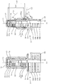
図1に示すように、本実施形態における注出部材1は、注出部材本体2と、注出部材本体2に装着される開封キャップ3とを備えている。注出部材1が備えるこれらの部材は、例えば、ポリプロピレン,ポリエチレン等のポリオレフィン系樹脂などの熱可塑性樹脂を用いて、射出成形などの成形手段によって製造することができる。
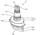
また、図2に示すように、注出部材本体2は、基部23から円筒状に立ち上がる注出筒部22を有しており、注出筒部22と基部23との境界部には、水平に張り出すフランジ部2cが形成されている。そして、注出筒部22の先端側には、薄肉部21aを介して封止部21が形成されおり、封止部21を薄肉部21aで捩じ切ることによって、注出筒部22を開封できるようにしてある。
本実施形態では、注出部材本体2に装着された開封キャップ3が不必要に回転したり、引き抜かれたりして、封止部21が誤って捩じ切られるなどすることによる誤開封を防止するために、注出筒部22の基部23側に三方突部5が形成されている。
また、注出部材本体2には、基部23に対して下方に位置する舟形部24が形成されている。この舟形部24と基部23とは、注出筒部22内に連通して通液路2aが形成されるように、その内部を貫通させてある。
注出部材本体2に形成される舟形部24は、例えば、樹脂フィルムのような軟包材を製袋してなるパウチなどの容器に、注出部材1を内容物の注出口として取り付ける際の溶着部となる部位であり、左右に水平に張り出す三つの溶着基板24aと、基部23との境界部に位置する位置決め基板24bとを有している。これにより、内容物の注出口として注出部材1をパウチに取り付ける際には、図1にパウチの一例を二点鎖線で示すように、パウチを形成する軟包材の端縁に位置決め基板24bを当接させて、その位置決めをしつつ、溶着基板24aの側面に当該軟包材が溶着されるようになっている。
一方、開封キャップ3は、天板3aを備えた筒状の部材とされている。そして、開封キャップ3は、注出部材本体2に、その注出筒部22の先端側に形成された封止部21と基部23側に形成された三方突部5との二か所で係合するように打栓により装着されて、注出筒部22の周囲を覆うようになっている。
開封キャップ3を注出部材本体2の封止部21に係合させるには、例えば、図2などに示すように、封止部21に、その周縁に沿って鍔状に突出する突出部21bを形成するとともに、この突出部21bと係合する係合リブ3bを開封キャップ3の内周面に形成するなどすればよい。これにより、注出部材本体2に開封キャップ3を打栓する際に、開封キャップ3に形成された係合リブ3bが、封止部21に形成された突出部21bを乗り越えて互いに係合することで、開封キャップ3と封止部21との係合がなされるようにすることができる。
開封キャップ3には、注出部材本体2に開封キャップ3を打栓する際に、開封キャップ3が傾いてしまったり、開封キャップ3が必要以上に注出部材本体2側に押しつけられて、封止部21が傾くなどして薄肉部21aが破断して誤開封してしまったりするのを防止するなどの目的で、図5及び図6に示すように、その開口端側の端面から垂下して、注出部材本体2に形成されたフランジ部2cに当接する突片3fを必要に応じて形成してもよい。
また、開封キャップ3は、注出部材本体2に同心状に装着されるところ、その中心軸C回りに、右回り、又は左回りのいずれかの方向に回転させることによって、図7に示すように、開封キャップ3に係合された封止部21が薄肉部21aで捩じ切られて、注出筒部22を開封するようにしてある。これによって、注出部材1が取り付けられたパウチなどの容器内の内容物を、通液路2aを通過して注出筒部22の先端から注出できるようになっている。
なお、図7は、注出筒部本体2から開封キャップ3を取り外した状態を示す説明図であり、開封キャップ3は一部を省略した断面を示している。
なお、図7は、注出筒部本体2から開封キャップ3を取り外した状態を示す説明図であり、開封キャップ3は一部を省略した断面を示している。
開封キャップ3による封止部21の捩じ切りを可能とするには、例えば、図2(a)に示すように、封止部21に、その径方向に張り出す一対の張り出し片21cを形成するとともに、この張り出し片21cが係止される係止溝3cを開封キャップ3の内周面に形成するなどすればよい。これにより、開封キャップ3を中心軸C回りに、右回り、又は左回りのいずれかの方向に回転させると、これに伴って封止部21も回転し、薄肉部21aで捩じ切られるようにすることができる。捩じ切られた封止部21は、図7に示すように、捩じ切られた後も開封キャップ3の係合リブ3bと封止部21の突出部21bの係合が維持されるようにすることで、開封キャップ3からの脱落を防止することができる。
このような開封キャップ3を注出部材本体2に装着すれば、注出部材本体2の注出筒部22が開封キャップ3で覆われた状態のまま使用者の手指が注出筒部22に触れることなく、封止部21を捩じ切って注出筒部22を開封することが可能となり、開封された注出筒部22の先端から内容物を注出させることができる。すなわち、使用者は、例えば、一方の手で注出部材本体2の基部23側を把持しつつ、他方の手で開封キャップ3を回転させるだけで、注出筒部22に触れることなく衛生的に封止部21を捩じ切ることができる。
本実施形態では、注出部材本体2に装着された開封キャップ3が不必要に回転したり、引き抜かれたりして、封止部21が誤って捩じ切られるなどすることによる誤開封を防止するために、封止部21の突出部21bと開封キャップ3の係合リブ3bとの係合に加え、注出筒部22の基部23側に形成された三方突部5と開封キャップ3の開口端側の内周面に形成された係合突部3dとの係合によって、開封キャップ3が注出部材本体2に装着されている。
注出部材本体2の注出筒部22に形成される三方突部5は、これと係合する開封キャップ3側の係合突部3dの上方及び左右の三方を囲み、開封キャップ3が不必要に回転したり、引き抜かれたりしてしまうのを抑止できるように、注出筒部22の周面に沿って延在する梁状突部5aと、この梁状突部の両端から注出筒部22の周面に沿って垂下するように形成された左右一対の柱状突部5bとからなるゲート状に形成されている。このような三方突部5を注出筒部22に形成することで、突部を別々に形成した場合と比較して樹脂材料の使用量の増加を抑えることができ、注出筒部22の基部23側の肉厚を部分的に厚くして、その強度を高めることもできる。
そして、注出部材本体2に開封キャップ3が装着される際に、開封キャップ3側に形成された係合突部3dが、注出部材本体2側に形成された三方突部5の梁状突部5aを乗り越えて互いに係合し、係合突部3dが梁状突部5aに突き当たることによって開封キャップ3の上方への動きが制限され、係合突部3dが柱状突部5bに突き当たることによって開封キャップ3の左右の動き(回転)が制限される。注出部材本体2に開封キャップ3を装着する際に、係合突部3dが三方突部5の梁状突部5aを乗り越え易いように、梁状突部5aの上面側は、中心軸Cを含む断面において直線状又は曲線状に傾斜するように形成するのが好ましい。
また、注出部材本体2に開封キャップ3が装着される際には、開封キャップ3に形成された係合リブ3bが、封止部21に形成された突出部21bを乗り越えて互いに係合することで、開封キャップ3と封止部21との係合がなされるようにしているのは前述した通りであるが、このとき、打栓による衝撃が封止部21に過剰に加わると、薄肉部21aが破断して誤開封してしまうことが考えられる。
このため、三方突部5の梁状突部5aの上面側に形成した斜面よりも、封止部21に形成される突出部21bの上面側が急傾斜するようにして、封止部21に過剰の衝撃が加わらないようにするのが好ましい。このためには、図2(b)に示すように、中心軸Cを含む断面における突出部21bの上端の接線L1と中心軸Cとのなす角度αが、中心軸Cを含む断面における三方突部5の梁状突部5aの上端の接線L2と中心軸Cとのなす角度βよりも小さくなるようにするのが好ましい。つまり、角度βよりも角度αを小さくすることで、開封キャップ3に形成された係合リブ3bが、封止部21に形成された突出部21bに係合する際の抵抗が小さくなり、これによって、封止部21への衝撃が小さくなるため、より誤開封を防ぐことができる。
さらに、注出部材本体2に開封キャップ3を装着する際に、開封キャップ3に形成された係合リブ3bが、封止部21に形成された突出部21bを乗り越えるタイミングと、開封キャップ3に形成された係合突部3dが、三方突部5の梁状突部5aを乗り越えるタイミングとが同じになるように、これらの相対的な位置関係を定めるのが好ましい。
これらのタイミングが合わずに、開封キャップ3に形成された係合リブ3bが、封止部21に形成された突出部21bを乗り越えるタイミングの方が速くなる場合には、組み付け精度の高い装置を用いて打栓しなければ、打栓時の衝撃が好ましくない方向から突出部21bに加わり、突出部21bが傾くなどすることによって、薄肉部21aが破断して誤開封してしまうおそれがある。また、開封キャップ3に形成された係合突部3dが、三方突部5の梁状突部5aを乗り越えるタイミングの方が速くなる場合にも、係合リブ3bが、単独で封止部21に形成された突出部21bを乗り越えることになってしまい、打栓時の衝撃によって薄肉部21aが破断して誤開封してしまうおそれがある。
開封キャップ3に形成された係合リブ3bが、封止部21に形成された突出部21bを乗り越えるタイミングと、開封キャップ3に形成された係合突部3dが、三方突部5の梁状突部5aを乗り越えるタイミングとが同じとなるようにするには、中心軸Cに沿った突出部21bの上端と三方突部5の梁状突部5aの上端との距離をLa1(図2(b)参照)、開封キャップ3の内周面に形成された係合リブ3bの最突出部と係合突部3dの最突出部との中心軸Cに沿った距離をLb(図6(b)参照)としたときに、Lb-La1≦0.5mmなる関係が成り立つのが好ましい。このような関係が成り立つようにすることで、注出部材本体2に開封キャップ3を打栓により装着する際に、係合リブ3bが突出部21bに当接するのとほぼ同時に、係合突部3dが三方突部5の梁状突部5aに当接し、その状態で打栓される。このため、打栓する際に突出部21bが傾くなどの不具合を有効に回避することができ、かつ、注出部材本体2への負荷が分散され、突出部21bにかかる衝撃を弱めることができるので、より誤開封を防ぐことができる。
さらに、中心軸Cに沿った突出部21bの下端と三方突部5の梁状突部5aの下端との距離をLa2(図2(b)参照)としたときに、上記距離Lbとの間には、Lb-La2≦0.5mmなる関係が成り立つのが好ましい。このような関係が成り立つようにすることで、開封キャップ3を引き抜く方向の遊びが少なくなるとともに、開封キャップ3を回転させずに垂直に引き上げたときに、係合リブ3bと係合する突出部21bと、係合突部3dと係合する三方突部5とにほぼ同時に力が加わるようになるため、注出部材本体2への負荷が分散され、突出部21bにかかる衝撃を弱めることができ、より誤開封を防ぐことができる。
また、注出部材本体2の注出筒部22に形成する三方突部5は、注出部材本体2の中心軸Cに対して対称に配置されるようにするのが好ましい。図示する例では、二つの三方突部5が、180°隔てて対向するように配置してあるが、これとともに、開封キャップ3に形成する係合突部3dも三方突部5の形成位置に対応して配置されるようにしてある。
本実施形態において、封止部21を捩じ切る際には、図8(a)に示すように、三方突部5と係合突部3dとが係合した状態から開封キャップ3を回転させることになるが、このとき、互いに係合しあう三方突部5と係合突部3dは弾性変形しながら、その係合が解除される。そして、係合突部3dが三方突部5の柱状突部5bを乗り越える際の抵抗、又は、振動が、クリック感として使用者に伝わってくる。さらに、開封キャップ3が中心軸C回りに半回転弱の角度で回転すると、図8(b)に示すように、係合突部3dが反対側の三方突部5の柱状突部5bに当接し、これによって、開封キャップ3は、これ以上の回転がなされないか、又は回転させ難い状態になる。よって、使用者は、開封キャップ3の回転が止められた感触により、封止部21の捩じ切りが完了したこと、又は既に完了していることを感覚的に知ることができる。
すなわち、このような態様にあっては、三方突部5と係合突部3dとの係合が解除される際のクリック感によって、開封開始時期を使用者に知らせ、図8(b)に示す状態で開封キャップ3の回転が妨げられるようにすることで、開封完了時期を使用者に知らせることができる。これにより、開封開始時期と開封完了時期とを使用者に感触的に知らせることができるとともに、実際の開封も完了し、開封キャップ3を上方へ引き抜くことが可能な状態にすることができる。
したがって、本実施形態によれば、封止部21を捩じ切る際に、開封キャップ3を必要以上に回転させて、無駄な作業時間を費やしてしまったり、開封キャップ3の回転が足りずに封止部21の捩じ切りが完了しないまま、開封キャップ2を無理に引き抜こうとして内容物をこぼしてしまったりするなどの不具合を回避することができる。
したがって、本実施形態によれば、封止部21を捩じ切る際に、開封キャップ3を必要以上に回転させて、無駄な作業時間を費やしてしまったり、開封キャップ3の回転が足りずに封止部21の捩じ切りが完了しないまま、開封キャップ2を無理に引き抜こうとして内容物をこぼしてしまったりするなどの不具合を回避することができる。
また、封止部21の捩じ切りに必要な回転角度を、開封キャップ3の回転を開始してから、三方突部5との係合が解除された係合突部3dが、反対側の三方突部5の柱状突部5bに当接するまでの回転角度よりも小さくなるように、薄肉部21aの肉厚や、その材料などを適宜調整することができる。
以上のような注出部材1は、例えば、図9に示すように、特開2009-173324やWO2006/067880で開示された、経腸栄養剤、流動食などを内容物として密封充填する、吊下穴H1や指掛け穴H2が穿設され、ジッパーGが設けられたパウチPに取り付けて使用することができる。そして、封止部21を捩じ切って開封キャップ3を取り外してから、開封された注出筒部22をカテーテルなどのチューブに差し込んで接続した後に、内容物を注出することにより、患者への投与がなされる。
以上、本発明について、好ましい実施形態を示して説明したが、本発明は、前述した実施形態にのみ限定されるものではなく、本発明の範囲で種々の変更実施が可能であることは言うまでもない。
本発明に係る注出部材は、衛生的に開封する必要がある内容物が密封充填される容器に、特に好適に利用することができる。
1 注出部材
2 注出部材本体
21 封止部
21a 薄肉部
21b 突出部
22 注出筒部
23 基部
3 開封キャップ
3b 係合リブ
3d 係合突部
5 三方突部
5a 梁状突部
5b 柱状突部
2 注出部材本体
21 封止部
21a 薄肉部
21b 突出部
22 注出筒部
23 基部
3 開封キャップ
3b 係合リブ
3d 係合突部
5 三方突部
5a 梁状突部
5b 柱状突部
Claims (5)
- 注出部材本体と、前記注出部材本体に同心状に装着される開封キャップとを備え、前記注出部材本体が、基部から円筒状に立ち上がる注出筒部を有し、前記注出筒部の先端側には、薄肉部を介して封止部が形成されており、前記封止部に係合させた前記開封キャップを中心軸回りに回転させることによって、前記封止部が前記薄肉部で捩じ切られて、前記注出筒部を開封するようにした注出部材であって、
前記開封キャップの開口端側の内周面に係合突部が形成され、
前記係合突部と係合し、かつ、前記係合突部の上方及び左右の三方を囲む三方突部が前記注出筒部の前記基部側に形成されていることを特徴とする注出部材。 - 前記三方突部が、前記注出筒部の周面に沿って延在する梁状突部と、前記梁状突部の両端から前記注出筒部の周面に沿って垂下する左右一対の柱状突部とからなり、
前記係合突部が前記梁状突部に突き当たることによって前記開封キャップの上方への動きが制限され、前記係合突部が前記柱状突部に突き当たることによって前記開封キャップの左右の動きが制限されている請求項1に記載の注出部材。 - 前記封止部の周縁に沿って鍔状に突出する突出部を形成するとともに、前記突出部と係合する係合リブを前記開封キャップの内周面に形成することにより、前記開封キャップが前記封止部に係合されるようになっており、
中心軸を含む断面における前記突出部の上端の接線と中心軸とのなす角度αが、中心軸を含む断面における前記梁状突部の上端の接線と中心軸とのなす角度βよりも小さい請求項2に記載の注出部材。 - 中心軸に沿った前記突出部の上端と前記梁状突部の上端との距離La1と、前記開封キャップの内周面に形成された前記係合リブの最突出部と前記係合突部の最突出部との中心軸に沿った距離Lbとの間に、Lb-La1≦0.5mmなる関係が成り立つ請求項3に記載の注出部材。
- 中心軸に沿った前記突出部の下端と前記梁状突部の下端との距離La2と、前記開封キャップの内周面に形成された前記係合リブの最突出部と前記係合突部の最突出部との中心軸に沿った距離Lbとの間に、Lb-La2≦0.5mmなる関係が成り立つ請求項3又は4に記載の注出部材。
Applications Claiming Priority (2)
| Application Number | Priority Date | Filing Date | Title |
|---|---|---|---|
| JP2012257821A JP6060644B2 (ja) | 2012-11-26 | 2012-11-26 | 注出部材 |
| JP2012-257821 | 2012-11-26 |
Publications (1)
| Publication Number | Publication Date |
|---|---|
| WO2014080581A1 true WO2014080581A1 (ja) | 2014-05-30 |
Family
ID=50775778
Family Applications (1)
| Application Number | Title | Priority Date | Filing Date |
|---|---|---|---|
| PCT/JP2013/006544 Ceased WO2014080581A1 (ja) | 2012-11-26 | 2013-11-06 | 注出部材 |
Country Status (2)
| Country | Link |
|---|---|
| JP (1) | JP6060644B2 (ja) |
| WO (1) | WO2014080581A1 (ja) |
Citations (3)
| Publication number | Priority date | Publication date | Assignee | Title |
|---|---|---|---|---|
| JPS4887249U (ja) * | 1972-01-27 | 1973-10-22 | ||
| JP2008030759A (ja) * | 2006-07-26 | 2008-02-14 | Dainippon Printing Co Ltd | 保護キャップ付き注出口 |
| JP2009102020A (ja) * | 2007-10-19 | 2009-05-14 | Toyo Seikan Kaisha Ltd | 注出部材 |
-
2012
- 2012-11-26 JP JP2012257821A patent/JP6060644B2/ja active Active
-
2013
- 2013-11-06 WO PCT/JP2013/006544 patent/WO2014080581A1/ja not_active Ceased
Patent Citations (3)
| Publication number | Priority date | Publication date | Assignee | Title |
|---|---|---|---|---|
| JPS4887249U (ja) * | 1972-01-27 | 1973-10-22 | ||
| JP2008030759A (ja) * | 2006-07-26 | 2008-02-14 | Dainippon Printing Co Ltd | 保護キャップ付き注出口 |
| JP2009102020A (ja) * | 2007-10-19 | 2009-05-14 | Toyo Seikan Kaisha Ltd | 注出部材 |
Also Published As
| Publication number | Publication date |
|---|---|
| JP2014104993A (ja) | 2014-06-09 |
| JP6060644B2 (ja) | 2017-01-18 |
Similar Documents
| Publication | Publication Date | Title |
|---|---|---|
| JP4987661B2 (ja) | 注出部材 | |
| JP6216037B2 (ja) | 貯蔵又は点滴容器 | |
| WO2010095273A1 (ja) | 容器用の捩じ切り開封機構 | |
| JP6202528B2 (ja) | ヒンジキャップ | |
| CN104870334A (zh) | 再充填容器用注出结构 | |
| JP2009046184A (ja) | 容器用の捩じ切り開封機構 | |
| JP5203260B2 (ja) | 内容物の詰替えに用いられる注出具 | |
| BR112016007285B1 (pt) | Tampa de medição | |
| JP6060644B2 (ja) | 注出部材 | |
| JP4706276B2 (ja) | 流体容器用注出装置 | |
| JP6202523B2 (ja) | ヒンジキャップ | |
| JP2014129100A (ja) | 詰め替え容器 | |
| JP7188958B2 (ja) | カバー部材付きスパウト | |
| JP7195817B2 (ja) | カバー付きスパウト | |
| JP6340727B2 (ja) | 詰め替え容器 | |
| JP5269360B2 (ja) | ヒンジキャップ | |
| JP6053462B2 (ja) | 折り取りスパウト、スパウト付きパウチおよびその製造方法 | |
| JP4894524B2 (ja) | 簡易注出具 | |
| JP6052766B2 (ja) | 液注出容器のキャップ | |
| JP2010222017A (ja) | 開封具 | |
| KR200358633Y1 (ko) | 스포이드 장착용 액상 저장용기 | |
| JP6501697B2 (ja) | 蓋付きカップ容器 | |
| JP3464973B2 (ja) | 開封防止リング付きキャップ及びその開閉具 | |
| JP6030361B2 (ja) | 開封栓および開封栓付き収容体 | |
| JP2014166855A (ja) | 詰め替え容器 |
Legal Events
| Date | Code | Title | Description |
|---|---|---|---|
| 121 | Ep: the epo has been informed by wipo that ep was designated in this application |
Ref document number: 13856869 Country of ref document: EP Kind code of ref document: A1 |
|
| NENP | Non-entry into the national phase |
Ref country code: DE |
|
| 122 | Ep: pct application non-entry in european phase |
Ref document number: 13856869 Country of ref document: EP Kind code of ref document: A1 |