WO2014077228A1 - 感光性転写材料、感光性低屈折率転写層を有する基板、感光性低屈折率転写層の製造方法、永久膜の形成方法、光学デバイス及びその製造方法 - Google Patents
感光性転写材料、感光性低屈折率転写層を有する基板、感光性低屈折率転写層の製造方法、永久膜の形成方法、光学デバイス及びその製造方法 Download PDFInfo
- Publication number
- WO2014077228A1 WO2014077228A1 PCT/JP2013/080492 JP2013080492W WO2014077228A1 WO 2014077228 A1 WO2014077228 A1 WO 2014077228A1 JP 2013080492 W JP2013080492 W JP 2013080492W WO 2014077228 A1 WO2014077228 A1 WO 2014077228A1
- Authority
- WO
- WIPO (PCT)
- Prior art keywords
- group
- photosensitive
- refractive index
- low refractive
- transfer material
- Prior art date
- Legal status (The legal status is an assumption and is not a legal conclusion. Google has not performed a legal analysis and makes no representation as to the accuracy of the status listed.)
- Ceased
Links
- UNAOIYAQYNAFDX-FLFQWRMESA-N CCCCCC/C(/C(c(cc1)ccc1Sc1ccccc1)=O)=C/[IH]OC(c1ccccc1)=O Chemical compound CCCCCC/C(/C(c(cc1)ccc1Sc1ccccc1)=O)=C/[IH]OC(c1ccccc1)=O UNAOIYAQYNAFDX-FLFQWRMESA-N 0.000 description 1
- OHBQPCCCRFSCAX-UHFFFAOYSA-N COc(cc1)ccc1OC Chemical compound COc(cc1)ccc1OC OHBQPCCCRFSCAX-UHFFFAOYSA-N 0.000 description 1
- IYYZUPMFVPLQIF-UHFFFAOYSA-N c(cc1)cc2c1[s]c1c2cccc1 Chemical compound c(cc1)cc2c1[s]c1c2cccc1 IYYZUPMFVPLQIF-UHFFFAOYSA-N 0.000 description 1
Images


Classifications
-
- C—CHEMISTRY; METALLURGY
- C08—ORGANIC MACROMOLECULAR COMPOUNDS; THEIR PREPARATION OR CHEMICAL WORKING-UP; COMPOSITIONS BASED THEREON
- C08F—MACROMOLECULAR COMPOUNDS OBTAINED BY REACTIONS ONLY INVOLVING CARBON-TO-CARBON UNSATURATED BONDS
- C08F290/00—Macromolecular compounds obtained by polymerising monomers on to polymers modified by introduction of aliphatic unsaturated end or side groups
- C08F290/08—Macromolecular compounds obtained by polymerising monomers on to polymers modified by introduction of aliphatic unsaturated end or side groups on to polymers modified by introduction of unsaturated side groups
- C08F290/12—Polymers provided for in subclasses C08C or C08F
-
- B—PERFORMING OPERATIONS; TRANSPORTING
- B32—LAYERED PRODUCTS
- B32B—LAYERED PRODUCTS, i.e. PRODUCTS BUILT-UP OF STRATA OF FLAT OR NON-FLAT, e.g. CELLULAR OR HONEYCOMB, FORM
- B32B27/00—Layered products comprising a layer of synthetic resin
- B32B27/06—Layered products comprising a layer of synthetic resin as the main or only constituent of a layer, which is next to another layer of the same or of a different material
- B32B27/08—Layered products comprising a layer of synthetic resin as the main or only constituent of a layer, which is next to another layer of the same or of a different material of synthetic resin
-
- B—PERFORMING OPERATIONS; TRANSPORTING
- B32—LAYERED PRODUCTS
- B32B—LAYERED PRODUCTS, i.e. PRODUCTS BUILT-UP OF STRATA OF FLAT OR NON-FLAT, e.g. CELLULAR OR HONEYCOMB, FORM
- B32B27/00—Layered products comprising a layer of synthetic resin
- B32B27/18—Layered products comprising a layer of synthetic resin characterised by the use of special additives
- B32B27/20—Layered products comprising a layer of synthetic resin characterised by the use of special additives using fillers, pigments, thixotroping agents
-
- B—PERFORMING OPERATIONS; TRANSPORTING
- B32—LAYERED PRODUCTS
- B32B—LAYERED PRODUCTS, i.e. PRODUCTS BUILT-UP OF STRATA OF FLAT OR NON-FLAT, e.g. CELLULAR OR HONEYCOMB, FORM
- B32B27/00—Layered products comprising a layer of synthetic resin
- B32B27/30—Layered products comprising a layer of synthetic resin comprising vinyl (co)polymers; comprising acrylic (co)polymers
- B32B27/308—Layered products comprising a layer of synthetic resin comprising vinyl (co)polymers; comprising acrylic (co)polymers comprising acrylic (co)polymers
-
- B—PERFORMING OPERATIONS; TRANSPORTING
- B32—LAYERED PRODUCTS
- B32B—LAYERED PRODUCTS, i.e. PRODUCTS BUILT-UP OF STRATA OF FLAT OR NON-FLAT, e.g. CELLULAR OR HONEYCOMB, FORM
- B32B3/00—Layered products comprising a layer with external or internal discontinuities or unevennesses, or a layer of non-planar shape; Layered products comprising a layer having particular features of form
- B32B3/26—Layered products comprising a layer with external or internal discontinuities or unevennesses, or a layer of non-planar shape; Layered products comprising a layer having particular features of form characterised by a particular shape of the outline of the cross-section of a continuous layer; characterised by a layer with cavities or internal voids ; characterised by an apertured layer
- B32B3/30—Layered products comprising a layer with external or internal discontinuities or unevennesses, or a layer of non-planar shape; Layered products comprising a layer having particular features of form characterised by a particular shape of the outline of the cross-section of a continuous layer; characterised by a layer with cavities or internal voids ; characterised by an apertured layer characterised by a layer formed with recesses or projections, e.g. hollows, grooves, protuberances, ribs
-
- B—PERFORMING OPERATIONS; TRANSPORTING
- B32—LAYERED PRODUCTS
- B32B—LAYERED PRODUCTS, i.e. PRODUCTS BUILT-UP OF STRATA OF FLAT OR NON-FLAT, e.g. CELLULAR OR HONEYCOMB, FORM
- B32B5/00—Layered products characterised by the non- homogeneity or physical structure, i.e. comprising a fibrous, filamentary, particulate or foam layer; Layered products characterised by having a layer differing constitutionally or physically in different parts
- B32B5/14—Layered products characterised by the non- homogeneity or physical structure, i.e. comprising a fibrous, filamentary, particulate or foam layer; Layered products characterised by having a layer differing constitutionally or physically in different parts characterised by a layer differing constitutionally or physically in different parts, e.g. denser near its faces
- B32B5/142—Variation across the area of the layer
-
- C—CHEMISTRY; METALLURGY
- C08—ORGANIC MACROMOLECULAR COMPOUNDS; THEIR PREPARATION OR CHEMICAL WORKING-UP; COMPOSITIONS BASED THEREON
- C08F—MACROMOLECULAR COMPOUNDS OBTAINED BY REACTIONS ONLY INVOLVING CARBON-TO-CARBON UNSATURATED BONDS
- C08F299/00—Macromolecular compounds obtained by interreacting polymers involving only carbon-to-carbon unsaturated bond reactions, in the absence of non-macromolecular monomers
-
- G—PHYSICS
- G03—PHOTOGRAPHY; CINEMATOGRAPHY; ANALOGOUS TECHNIQUES USING WAVES OTHER THAN OPTICAL WAVES; ELECTROGRAPHY; HOLOGRAPHY
- G03F—PHOTOMECHANICAL PRODUCTION OF TEXTURED OR PATTERNED SURFACES, e.g. FOR PRINTING, FOR PROCESSING OF SEMICONDUCTOR DEVICES; MATERIALS THEREFOR; ORIGINALS THEREFOR; APPARATUS SPECIALLY ADAPTED THEREFOR
- G03F7/00—Photomechanical, e.g. photolithographic, production of textured or patterned surfaces, e.g. printing surfaces; Materials therefor, e.g. comprising photoresists; Apparatus specially adapted therefor
- G03F7/004—Photosensitive materials
- G03F7/027—Non-macromolecular photopolymerisable compounds having carbon-to-carbon double bonds, e.g. ethylenic compounds
- G03F7/028—Non-macromolecular photopolymerisable compounds having carbon-to-carbon double bonds, e.g. ethylenic compounds with photosensitivity-increasing substances, e.g. photoinitiators
-
- G—PHYSICS
- G03—PHOTOGRAPHY; CINEMATOGRAPHY; ANALOGOUS TECHNIQUES USING WAVES OTHER THAN OPTICAL WAVES; ELECTROGRAPHY; HOLOGRAPHY
- G03F—PHOTOMECHANICAL PRODUCTION OF TEXTURED OR PATTERNED SURFACES, e.g. FOR PRINTING, FOR PROCESSING OF SEMICONDUCTOR DEVICES; MATERIALS THEREFOR; ORIGINALS THEREFOR; APPARATUS SPECIALLY ADAPTED THEREFOR
- G03F7/00—Photomechanical, e.g. photolithographic, production of textured or patterned surfaces, e.g. printing surfaces; Materials therefor, e.g. comprising photoresists; Apparatus specially adapted therefor
- G03F7/004—Photosensitive materials
- G03F7/027—Non-macromolecular photopolymerisable compounds having carbon-to-carbon double bonds, e.g. ethylenic compounds
- G03F7/032—Non-macromolecular photopolymerisable compounds having carbon-to-carbon double bonds, e.g. ethylenic compounds with binders
-
- G—PHYSICS
- G03—PHOTOGRAPHY; CINEMATOGRAPHY; ANALOGOUS TECHNIQUES USING WAVES OTHER THAN OPTICAL WAVES; ELECTROGRAPHY; HOLOGRAPHY
- G03F—PHOTOMECHANICAL PRODUCTION OF TEXTURED OR PATTERNED SURFACES, e.g. FOR PRINTING, FOR PROCESSING OF SEMICONDUCTOR DEVICES; MATERIALS THEREFOR; ORIGINALS THEREFOR; APPARATUS SPECIALLY ADAPTED THEREFOR
- G03F7/00—Photomechanical, e.g. photolithographic, production of textured or patterned surfaces, e.g. printing surfaces; Materials therefor, e.g. comprising photoresists; Apparatus specially adapted therefor
- G03F7/004—Photosensitive materials
- G03F7/038—Macromolecular compounds which are rendered insoluble or differentially wettable
-
- B—PERFORMING OPERATIONS; TRANSPORTING
- B32—LAYERED PRODUCTS
- B32B—LAYERED PRODUCTS, i.e. PRODUCTS BUILT-UP OF STRATA OF FLAT OR NON-FLAT, e.g. CELLULAR OR HONEYCOMB, FORM
- B32B2264/00—Composition or properties of particles which form a particulate layer or are present as additives
- B32B2264/10—Inorganic particles
- B32B2264/102—Oxide or hydroxide
-
- B—PERFORMING OPERATIONS; TRANSPORTING
- B32—LAYERED PRODUCTS
- B32B—LAYERED PRODUCTS, i.e. PRODUCTS BUILT-UP OF STRATA OF FLAT OR NON-FLAT, e.g. CELLULAR OR HONEYCOMB, FORM
- B32B2307/00—Properties of the layers or laminate
- B32B2307/40—Properties of the layers or laminate having particular optical properties
- B32B2307/418—Refractive
-
- B—PERFORMING OPERATIONS; TRANSPORTING
- B32—LAYERED PRODUCTS
- B32B—LAYERED PRODUCTS, i.e. PRODUCTS BUILT-UP OF STRATA OF FLAT OR NON-FLAT, e.g. CELLULAR OR HONEYCOMB, FORM
- B32B2457/00—Electrical equipment
-
- B—PERFORMING OPERATIONS; TRANSPORTING
- B32—LAYERED PRODUCTS
- B32B—LAYERED PRODUCTS, i.e. PRODUCTS BUILT-UP OF STRATA OF FLAT OR NON-FLAT, e.g. CELLULAR OR HONEYCOMB, FORM
- B32B2457/00—Electrical equipment
- B32B2457/20—Displays, e.g. liquid crystal displays, plasma displays
- B32B2457/202—LCD, i.e. liquid crystal displays
Definitions
- the present invention relates to a photosensitive transfer material, a substrate having a photosensitive low refractive index transfer layer, a method for producing a photosensitive low refractive index transfer layer, a method for forming a permanent film, an optical device, and a method for producing the same.
- Low refractive index film is anti-reflection film, reflection film, semi-transmission semi-reflection film, visible light reflection infrared transmission film, infrared reflection visible light transmission film, blue reflection film, green reflection or red reflection film, bright line cut filter, color correction
- An optical functional film included in the film is formed on the optical member.
- optical members with a flat surface shape but also optical function members such as Fresnel lenses, lenticular lenses, and microlenses used in the screens of brightness enhancement lens films and diffusion films for liquid crystal backlights and video projection televisions are all resin.
- the desired geometrical optical performance is obtained because the material has a fine structure, but an optical functional film including a low refractive index film is also required on the surface of the fine structure.
- the photosensitive resin compositions described in Patent Documents 1 and 2 are known.
- a photosensitive transfer material described in Patent Document 3 is known.
- An object of the present invention is to provide a photosensitive transfer material having a low refractive index, a high light transmission efficiency, and an excellent in-plane film thickness uniformity after transfer.
- ⁇ 1> At least a photosensitive low refractive index material layer on a support, wherein the photosensitive low refractive index material layer comprises (Component A) hollow or porous particles, (Component B) a photopolymerization initiator, A photosensitive transfer material comprising: (Component C) a polymer having a polymerizable functional group; and (Component D) a monomer.
- Component A hollow or porous particles
- Component B a photopolymerization initiator
- a photosensitive transfer material comprising: (Component C) a polymer having a polymerizable functional group; and (Component D) a monomer.
- Transfer material ⁇ 10> a substrate having a photosensitive low refractive index transfer layer obtained by transferring the photosensitive low refractive index material layer from the photosensitive transfer material according to any one of ⁇ 1> to ⁇ 9>, ⁇ 11>
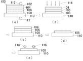
- a method for producing a photosensitive low refractive index transfer layer comprising: a step of laminating a film on a member to be transferred; and a step of peeling a support of the photosensitive transfer material.
- a step of preparing the photosensitive transfer material according to any one of ⁇ 1> to ⁇ 9>, the photosensitive transfer material so that a member to be transferred and the photosensitive low refractive index material layer are in contact with each other A method of forming a permanent film, including a step of laminating a film on the member to be transferred, a step of peeling a support of the photosensitive transfer material, and a step of exposing the transferred photosensitive low refractive index material layer, ⁇ 13> The step of preparing the photosensitive transfer material according to any one of ⁇ 1> to ⁇ 9>, wherein the photosensitive low refraction is used as at least one layer between the backlight module substrate and the color filter substrate.
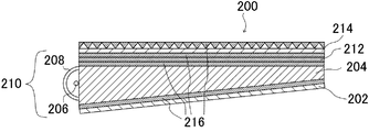
- An optical device including a step of laminating the photosensitive transfer material so that a refractive index material layer and the backlight module substrate or the color filter substrate are in contact with each other, and a step of peeling the support of the photosensitive transfer material Method, ⁇ 14>
- a photosensitive transfer material capable of obtaining a layer having a low refractive index, high light transmission efficiency, and excellent in-plane film thickness uniformity after transfer.
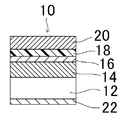
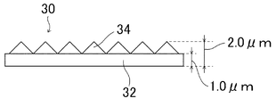
- FIG. 5 is a schematic diagram of an aa cross section of the prism sheet substrate of FIG. 4. It is a cross-sectional schematic diagram of the transmittance
- the description which does not describe substitution and non-substitution includes what does not have a substituent and what has a substituent.
- the “alkyl group” includes not only an alkyl group having no substituent (unsubstituted alkyl group) but also an alkyl group having a substituent (substituted alkyl group).
- “active light” or “radiation” in the present specification means, for example, an emission line spectrum of a mercury lamp, far ultraviolet rays represented by an excimer laser, extreme ultraviolet rays (EUV light), X-rays, electron beams, and the like. . In the present invention, light means actinic rays or radiation.
- exposure in this specification is not only exposure with far-ultraviolet rays such as mercury lamps and excimer lasers, X-rays, EUV light, but also drawing with particle beams such as electron beams and ion beams. Are also included in the exposure.
- mass% and wt% are synonymous, and “part by mass” and “part by weight” are synonymous. In the present invention, a combination of two or more preferred embodiments is more preferred.
- the photosensitive transfer material of the present invention has at least a photosensitive low refractive index material layer on a support, and the photosensitive low refractive index material layer comprises (Component A) hollow or porous particles, and (Component B). It contains a photopolymerization initiator, (Component C) a polymer having a polymerizable functional group, and (Component D) a monomer.
- the photosensitive low refractive index material layer is a negative resist layer and is preferably a layer having a property of being cured by irradiation with actinic rays.
- the photosensitive transfer material of the present invention is preferably a photosensitive transfer material for forming an optical device, more preferably a photosensitive transfer material for forming a display device, and a photosensitive transfer material for forming a backlight unit. More preferably, it is particularly preferably a photosensitive transfer material for forming a backlight unit of a touch panel member.
- the low refractive index film (layer obtained by transferring and curing the photosensitive low refractive index material layer) obtained from the photosensitive transfer material of the present invention has a low refractive index.
- the low refractive index film (layer obtained by transferring and curing the photosensitive low refractive index material layer) obtained from the photosensitive transfer material of the present invention exhibits excellent low refractive index properties.
- the refractive index (wavelength 589 nm, measurement temperature 25 ° C.) of the low refractive index film is preferably 1.35 or less, more preferably 1.10 to 1.34. It is particularly preferably 23 to 1.33.
- the refractive index is preferably a value measured at a wavelength of 589 nm and 25 ° C.
- the thickness of the photosensitive low refractive index material layer is preferably 0.01 to 2.0 ⁇ m, more preferably 0.1 to 1.5 ⁇ m, and still more preferably 0.2 to 1.0 ⁇ m.
- the thickness of the low refractive index film is preferably 0.01 to 2.0 ⁇ m, more preferably 0.1 to 1.5 ⁇ m, and still more preferably 0.2 to 1.0 ⁇ m.
- the photosensitive low refractive index material layer contains (Component A) hollow or porous particles.
- the hollow particle is a structure having a cavity inside and refers to a particle having a cavity surrounded by an outer shell, and the porous particle refers to a particle having a large number of cavities on the surface and inside.
- the porosity of such particles is preferably 10-80%, more preferably 20-60%, and most preferably 30-60%.
- the porosity of the hollow or porous particles is preferably in the above range from the viewpoint of reducing the refractive index and maintaining the durability of the particles.
- the hollow or porous particles are more preferably hollow particles from the viewpoint of easily reducing the refractive index.
- Examples of the method for producing hollow particles include the method described in JP-A-2001-233611.
- Examples of the method for producing porous particles include the methods described in JP-A Nos. 2003-327424, 2003-335515, 2003-226516, 2003-238140, and the like.
- the hollow or porous particles have an average primary particle diameter of preferably 1 to 200 nm, more preferably 10 to 100 nm.
- the average primary particle diameter of the hollow or porous particles can be obtained from a photograph obtained by observing the dispersed particles with a transmission electron microscope. The projected area of the particles is obtained, and the equivalent circle diameter is obtained therefrom to obtain the average particle size (usually, 300 or more particles are measured in order to obtain the average particle size).
- the refractive index of the hollow or porous particles is preferably 1.10 to 1.40, more preferably 1.15 to 1.35, and particularly preferably 1.15 to 1.30.
- the refractive index here represents the refractive index of the entire particle.
- the refractive index of the hollow particle is an apparent refractive index, and is a value of the refractive index in a form including a medium.
- the refractive index can be measured by a conventional ellipsometer.
- the refractive index of the porous particles can also be measured using an Abbe refractometer (manufactured by Atago Co., Ltd.).
- the hollow or porous particles may be inorganic particles or organic particles such as resin particles, but hollow or porous inorganic particles are preferable from the viewpoint of lowering the refractive index.
- the inorganic low refractive index particles include particles of magnesium fluoride and silica, and silica particles are more preferable from the viewpoints of low refractive index properties, dispersion stability, and cost.
- the average primary particle diameter of these inorganic particles is preferably 1 to 100 nm, and more preferably 1 to 60 nm.
- the inorganic particles may be either crystalline or amorphous, and may be monodispersed particles or aggregated particles as long as a predetermined particle size is satisfied.
- the shape is most preferably a spherical shape, but may be a bead shape, a shape having a ratio of the major axis to the minor axis of 1 or more, or an indefinite shape. Further, the ratio of the major axis to the minor axis is preferably 100 or less.
- the specific surface area of the inorganic particles is preferably 10 to 2,000 m 2 / g, more preferably 20 to 1,800 m 2 / g, still more preferably 50 to 1,500 m 2 / g. .
- Inorganic particles are used in a dispersion or coating solution to stabilize the dispersion, or to increase the affinity and binding properties with the binder component, such as a physical surface such as plasma discharge treatment or corona discharge treatment.
- a physical surface such as plasma discharge treatment or corona discharge treatment.
- chemical surface treatment with a treatment, a surfactant, a coupling agent, or the like may be performed, particles that are chemically surface treated with a coupling agent are particularly preferable.
- an alkoxy metal compound eg, titanium coupling agent, silane coupling agent
- silane coupling treatment is particularly effective.
- the organosilyl group (monoorganosilyl, diorganosilyl, triorganosilyl group) becomes silica particles by the reaction of the silane compound and the silanol group. It binds to the surface.
- the organic group on the surface of the surface-treated silica particles include saturated or unsaturated hydrocarbon groups having 1 to 18 carbon atoms and halogenated hydrocarbon groups having 1 to 18 carbon atoms.
- the above-mentioned coupling agent may be used as a surface treatment agent for inorganic particles in order to perform surface treatment in advance before the preparation of the coating solution for low refractive index film, or may be further added as an additive during the preparation of the coating solution.
- the inorganic particles are preferably dispersed in the medium in advance before the surface treatment in order to reduce the load of the surface treatment.
- silica particle As a silica particle, what is marketed can be used preferably.
- Julia Catalysts Co., Ltd. through rear series isopropanol (IPA) dispersion, 4-methyl-2-pentanone (MIBK, methyl isobutyl ketone) dispersion, etc.
- OSCAL series Nissan Chemicals Snowtex series (IPA dispersion, ethylene glycol dispersion, methyl ethyl ketone (MEK) dispersion, dimethylacetamide dispersion, MIBK dispersion, propylene glycol monomethyl acetate dispersion, propylene glycol monomethyl ether dispersion, methanol dispersion, ethyl acetate dispersion, butyl acetate dispersion, xylene-n-butanol dispersion, Toluene dispersion, etc.), Silex manufactured by Nippon Steel Mining Co., Ltd., PL series produced by Fuso Chemical Industry Co., Ltd.
- the silica particles are added to the photosensitive composition as a dispersion containing silica particles and a dispersant (details of the dispersant will be described later), the content of the silica particles in the silica dispersion is 10 to 10%. 50 mass% is preferable, 15 to 40 mass% is more preferable, and 15 to 30 mass% is still more preferable.
- the hollow or porous particles may be used alone or in combination of two or more. When using 2 or more types together, you may use a hollow particle and a porous particle together, for example.
- the content of the hollow or porous particles with respect to the total mass of the photosensitive low refractive index material layer is preferably 5 to 95% by mass, more preferably 10 to 90% by mass, and 20 to 90% by mass. More preferably.
- the coating amount of the hollow or porous particles is preferably 1 ⁇ 100mg / m 2, more preferably 5 ⁇ 80mg / m 2, 10 ⁇ 60mg / m 2 Is more preferable.
- it is 1 mg / m 2 or more, the effect of lowering the refractive index and the effect of improving scratch resistance can be reliably obtained, and when it is 100 mg / m 2 or less, fine irregularities are formed on the film surface. It is possible to suppress deterioration of the integrated reflectance.
- the photosensitive low refractive index material layer contains a photopolymerization initiator.
- the photosensitive transfer material of the present invention having a photosensitive low refractive index material layer imparted with photosensitivity by containing a photopolymerization initiator in the photosensitive low refractive index material layer is a photoresist, a color resist, or an optical material. It can be suitably used for a coating material or the like.
- the photopolymerization initiator is not particularly limited and can be appropriately selected from known photopolymerization initiators. For example, those having photosensitivity to visible light from the ultraviolet region are preferred and photoexcited. It may be an activator that produces some action with a sensitizer and generates active radicals, or an initiator that initiates cationic polymerization depending on the type of monomer. Further, the photopolymerization initiator contains at least one component having a molecular extinction coefficient of 50 L / (mol ⁇ cm) or more within a wavelength range of about 200 to 800 nm (more preferably 300 to 450 nm). More preferably, it contains at least one component having a molecular extinction coefficient of 50 to 10 6 L / (mol ⁇ cm) within a wavelength range of about 200 to 800 nm (more preferably 300 to 450 nm). preferable.
- Examples of the photopolymerization initiator include a photoradical polymerization initiator and a photocationic polymerization initiator, and a photoradical polymerization initiator is preferable.
- radical photopolymerization initiator examples include halogenated hydrocarbon derivatives (for example, those having a triazine skeleton, those having an oxadiazole skeleton), hexaarylbiimidazole compounds, lophine dimers, benzoins, ketals.
- 2,3-dialkyldione compounds organic peroxides, thio compounds, disulfide compounds, azo compounds, borates, inorganic complexes, coumarins, ketone compounds (benzophenones, thioxanthones, thiochromanones, anthraquinones) Oximation of aromatic onium salts, fluoroamine compounds, ketoxime ethers, acetophenones (aminoacetophenone compounds, hydroxyacetophenone compounds), acylphosphine compounds such as acylphosphine oxides, and oxime derivatives Things and the like.
- halogenated hydrocarbon compound having a triazine skeleton examples include those described in Wakabayashi et al., Bull. Chem. Soc. Japan, 42, 2924 (1969), a compound described in British Patent No. 1388492, a compound described in JP-A-53-133428, a compound described in German Patent No. 3333724, F.I. C. J. Schaefer et al. Org. Chem. , 29, 1527 (1964), compounds described in JP-A-62-258241, compounds described in JP-A-5-281728, compounds described in JP-A-5-34920, US Pat. No. 4,221,976 And the compounds described in the book.
- Examples of the compound described in the above-mentioned US Pat. No. 4,221,976 include compounds having an oxadiazole skeleton (for example, 2-trichloromethyl-5-phenyl-1,3,4-oxadiazole, 2- Trichloromethyl-5- (4-chlorophenyl) -1,3,4-oxadiazole, 2-trichloromethyl-5- (1-naphthyl) -1,3,4-oxadiazole, 2-trichloromethyl-5 -(2-naphthyl) -1,3,4-oxadiazole, 2-tribromomethyl-5-phenyl-1,3,4-oxadiazole, 2-tribromomethyl-5- (2-naphthyl) -1,3,4-oxadiazole, 2-trichloromethyl-5-styryl-1,3,4-oxadiazole, 2-trichloromethyl-5- (4-chlorostyryl) ) -1,3,4-oxadia
- benzoins examples include benzoin, benzoin methyl ether, benzoin ethyl ether, benzoin isopropyl ether, benzyl dimethyl ketal, benzoin benzene sulfonate, benzoin toluene sulfonate, benzoin methyl ether, benzoin ethyl ether and benzoin isopropyl ether.
- borate examples include, for example, Japanese Patent Nos. 2764769 and 2002-116539, and “Rad Tech'98. Proceeding April” by Kunz, Martin et al., Pages 19 to 22 (1998, Chicago). ) And the like described in the organic borate. Further, compounds described in paragraphs 0022 to 0027 of JP-A-2002-116539 can be mentioned. Examples of other organic boron compounds include JP-A-6-348011, JP-A-7-128785, JP-A-7-140589, JP-A-7-306527, and JP-A-7-292014. Specific examples include organoboron transition metal coordination complexes and the like, and specific examples include ion complexes with cationic dyes.
- radical polymerization initiators other than the above, polyhalogen compounds (for example, 9-phenylacridine, 1,7-bis (9,9′-acridinyl) heptane, etc.), N-phenylglycine (for example, 9-phenylacridine, etc.) Carbon tetrabromide, phenyltribromomethylsulfone, phenyltrichloromethylketone, etc.), coumarins (eg 3- (2-benzofuroyl) -7-diethylaminocoumarin, 3- (2-benzofuroyl) -7- (1-pyrrolidinyl) ) Coumarin, 3-benzoyl-7-diethylaminocoumarin, 3- (2-methoxybenzoyl) -7-diethylaminocoumarin, 3- (4-dimethylaminobenzoyl) -7-diethylaminocoumarin, 3,3′-carbonylbis (5 , 7-di-n-propoxycou
- acylphosphine oxides for example, bis (2,4 , 6-Trimethylbenzoyl) phenylphosphite Oxide, bis (2,6-dimethoxybenzoyl) -2,4,4-trimethylpentyl phenylphosphine oxide, Lucirin TPO, etc.
- metallocenes e.g., bis (eta 5-2,4-cyclopentadiene-1-yl) Bis (2,6-difluoro-3- (1H-pyrrol-1-yl) phenyl) titanium, ⁇ 5 -cyclopentadienyl- ⁇ 6 -cumenyliron (1+) hexafluorophosphate (1-), etc.
- metallocenes e.g., bis (eta 5-2,4-cyclopentadiene-1-yl) Bis (2,6-difluoro-3- (1H-pyrrol-1-yl) phenyl) titanium, ⁇ 5 -cycl
- ketone compound examples include benzophenone, 2-methylbenzophenone, 3-methylbenzophenone, 4-methylbenzophenone, 4-methoxybenzophenone, 2-chlorobenzophenone, 4-chlorobenzophenone, 4-bromobenzophenone, 2-carboxybenzophenone, 2-ethoxycarbonylbenzolphenone, benzophenonetetracarboxylic acid or tetramethyl ester thereof, 4,4′-bis (dialkylamino) benzophenone (for example, 4,4′-bis (dimethylamino) benzophenone, 4,4′- Bisdicyclohexylamino) benzophenone, 4,4′-bis (diethylamino) benzophenone, 4,4′-bis (dihydroxyethylamino) benzophenone, 4-methoxy-4′-dimethylamino Benzophenone, 4,4'-dimethoxybenzophenone, 4-dimethylaminobenzophenone, 4-
- the radical polymerization initiator is more preferably a compound selected from the group consisting of aminoacetophenone compounds, hydroxyacetophenone compounds, acylphosphine compounds, and oxime compounds. More specifically, for example, an aminoacetophenone initiator described in JP-A-10-291969, an acylphosphine oxide initiator described in Japanese Patent No. 4225898, an oxime initiator, and an oxime initiator. As the agent, compounds described in JP-A-2001-233842 can also be used.
- aminoacetophenone compound commercially available products IRGACURE 907, IRGACURE 369, and IRGACURE 379 (trade names: all manufactured by BASF Japan Ltd.) can be used.
- acylphosphine-based initiator commercially available products such as IRGACURE 819 and DAROCUR TPO (trade names: both manufactured by BASF Japan Ltd.) can be used.
- the hydroxyacetophenone compound is preferably a compound represented by the following formula (V).
- R 1 represents a hydrogen atom, an alkyl group (preferably an alkyl group having 1 to 10 carbon atoms), an alkoxy group (preferably an alkoxy group having 1 to 10 carbon atoms), or a divalent organic compound. Represents a group.
- R 1 is a divalent organic group
- two photoactive hydroxyacetophenone structures that is, a structure in which the substituent R 1 is excluded from the compound represented by the formula (V)
- R 2 and R 3 each independently represent a hydrogen atom or an alkyl group (preferably an alkyl group having 1 to 10 carbon atoms).
- R 2 and R 3 may be bonded to form a ring (preferably a ring having 4 to 8 carbon atoms).
- Alkyl and alkoxy group in the R 1, the alkyl group in R 2 and R 3, as well, the ring R 2 and R 3 are formed by bonding, may further have a substituent.
- hydroxyacetophenone compound examples include 2-hydroxy-2-methyl-1-phenylpropan-1-one (DAROCUR 1173), 2-hydroxy-2-methyl-1-phenylbutan-1-one, 1- (4 -Methylphenyl) -2-hydroxy-2-methylpropan-1-one, 1- (4-isopropylphenyl) -2-methylpropan-1-one, 1- (4-butylphenyl) -2-hydroxy-2 -Methylpropan-1-one, 2-hydroxy-2-methyl-1- (4-octylphenyl) propan-1-one, 1- (4-dodecylphenyl) -2-methylpropan-1-one, 1- (4-methoxyphenyl) -2-methylpropan-1-one, 1- (4-methylthiophenyl) -2-methylpropan-1-one, 1- (4-chlorophenyl) -2-hydroxy-2-methylpropan-1-one, 1- (4-bromophenyl) -2-hydroxy-2-methylpropan-1-one,
- Irgacure 184 (IRGACURE 184), Darocur 1173 (DAROCURE 1173), Irgacure 127 (IRGACURE 127), Irgacure 2959 (IRGACURE 2959), Irgacure 1800 (IRGACURE URE 1800) from Ciba Specialty Chemicals. 1800), Irgacure 1870 (IRGACURE 1870) and Darocur 4265 (DAROCUR 4265) are also available.
- acylphosphine compound commercially available products IRGACURE 819, IRGACURE 819DW, DAROCUR TPO (trade names: all manufactured by BASF Japan Ltd.) can be used. Further, phosphine initiators described in JP2009-134098A can also be applied.
- Examples of oxime compounds include J.M. C. S. Perkin II (1979) pp. 1653-1660), J.M. C. S. Perkin II (1979) pp. 156-162, Journal of Photopolymer Science and Technology (1995), pp. 156-162. Examples thereof include compounds described in 202-232, JP-A 2000-66385, JP-A 2000-80068, JP-T 2004-534797, JP-A 2006-342166, and the like.
- IRGACURE OXE01 manufactured by BASF Japan
- IRGACURE OXE02 manufactured by BASF Japan
- CGI-124 manufactured by BASF Japan
- CGI-242 manufactured by BASF Japan
- the cyclic oxime compounds described in JP 2007-231000 A and JP 2007-322744 A can also be suitably used.
- an oxime compound having a specific substituent as disclosed in JP-A-2007-267979 and an oxime compound having a thioaryl group as described in JP-A-2009-191061 are exemplified.
- the oxime compound is preferably a compound represented by the following formula (I).
- the N—O bond of the oxime bond may be an (E) oxime compound, a (Z) oxime compound, or a mixture of (E) and (Z) isomers. Good.
- R and B each independently represent a monovalent substituent, A represents a divalent organic group, and Ar represents an aryl group.
- the monovalent substituent represented by R is preferably a monovalent nonmetallic atomic group.
- the monovalent nonmetallic atomic group include an alkyl group, an aryl group, an acyl group, an alkoxycarbonyl group, an aryloxycarbonyl group, a heterocyclic group, an alkylthiocarbonyl group, and an arylthiocarbonyl group.
- these groups may have one or more substituents.
- the substituent mentioned above may be further substituted by another substituent.
- substituents examples include a halogen atom, an aryloxy group, an alkoxycarbonyl group or an aryloxycarbonyl group, an acyloxy group, an acyl group, an alkyl group, and an aryl group.
- the alkyl group which may have a substituent is preferably an alkyl group having 1 to 30 carbon atoms, and specifically includes a methyl group, an ethyl group, a propyl group, a butyl group, a hexyl group, an octyl group, and a decyl group.
- the aryl group which may have a substituent is preferably an aryl group having 6 to 30 carbon atoms, and specifically includes a phenyl group, a biphenyl group, a 1-naphthyl group, a 2-naphthyl group, and a 9-anthryl group.
- 9-phenanthryl group 1-pyrenyl group, 5-naphthacenyl group, 1-indenyl group, 2-azurenyl group, 9-fluorenyl group, terphenyl group, quarterphenyl group, o-, m- and p-tolyl group, Xylyl group, o-, m- and p-cumenyl group, mesityl group, pentarenyl group, binaphthalenyl group, tarnaphthalenyl group, quarternaphthalenyl group, heptalenyl group, biphenylenyl group, indacenyl group, fluoranthenyl group, acenaphthylenyl group, ASEAN Trirenyl group, phenalenyl group, fluorenyl group, anthryl group, bianthracenyl group, Anthracenyl group, quarter anthracenyl group, anthraquinolyl group,
- the acyl group which may have a substituent is preferably an acyl group having 2 to 20 carbon atoms, specifically, an acetyl group, a propanoyl group, a butanoyl group, a trifluoroacetyl group, a pentanoyl group, a benzoyl group, 1-naphthoyl group, 2-naphthoyl group, 4-methylsulfanylbenzoyl group, 4-phenylsulfanylbenzoyl group, 4-dimethylaminobenzoyl group, 4-diethylaminobenzoyl group, 2-chlorobenzoyl group, 2-methylbenzoyl group, 2 -Methoxybenzoyl group, 2-butoxybenzoyl group, 3-chlorobenzoyl group, 3-trifluoromethylbenzoyl group, 3-cyanobenzoyl group, 3-nitrobenzoyl group, 4-fluorobenzoyl group, 4-cyanobenz
- the alkoxycarbonyl group which may have a substituent is preferably an alkoxycarbonyl group having 2 to 20 carbon atoms, and specifically includes a methoxycarbonyl group, an ethoxycarbonyl group, a propoxycarbonyl group, a butoxycarbonyl group, a hexyloxy group. Examples thereof include a carbonyl group, an octyloxycarbonyl group, a decyloxycarbonyl group, an octadecyloxycarbonyl group, and a trifluoromethyloxycarbonyl group.
- the heterocyclic group which may have a substituent is preferably an aromatic or aliphatic heterocyclic ring containing a nitrogen atom, an oxygen atom, a sulfur atom or a phosphorus atom.
- thienyl group benzo [b] thienyl group, naphtho [2,3-b] thienyl group, thiantenyl group, furyl group, pyranyl group, isobenzofuranyl group, chromenyl group, xanthenyl group, phenoxathiyl Nyl group, 2H-pyrrolyl group, pyrrolyl group, imidazolyl group, pyrazolyl group, pyridyl group, pyrazinyl group, pyrimidinyl group, pyridazinyl group, indolizinyl group, isoindolyl group, 3H-indolyl group, indolyl group, 1H-indazolyl group, pur
- alkylthiocarbonyl group which may have a substituent include a methylthiocarbonyl group, a propylthiocarbonyl group, a butylthiocarbonyl group, a hexylthiocarbonyl group, an octylthiocarbonyl group, a decylthiocarbonyl group, and an octadecylthiocarbonyl group.
- Examples thereof include a group and a trifluoromethylthiocarbonyl group.
- Preferred examples of the monovalent substituent represented by B in the above formula (I) include an aryl group, a heterocyclic group, an arylcarbonyl group, and a heterocyclic carbonyl group. These groups may have one or more substituents. Examples of the substituent include the above-described substituents. Moreover, the substituent mentioned above may be further substituted by another substituent.
- Y, X, and n have the same meanings as Y, X, and n in formula (II) described later, respectively, and preferred examples are also the same.
- Examples of the divalent organic group represented by A in the above formula (I) include an alkylene group having 1 to 12 carbon atoms, a cyclohexylene group having 6 to 12 carbon atoms, and an alkynylene group having 2 to 12 carbon atoms. These groups may have one or more substituents. Examples of the substituent include the above-described substituents. Moreover, the substituent mentioned above may be further substituted by another substituent.
- A is an alkylene substituted with an unsubstituted alkylene group or an alkyl group (for example, a methyl group, an ethyl group, a tert-butyl group, or a dodecyl group) from the viewpoint of increasing sensitivity and suppressing coloration due to heating.
- alkylene group substituted with alkenyl group for example, vinyl group, allyl group
- aryl group for example, phenyl group, p-tolyl group, xylyl group, cumenyl group, naphthyl group, anthryl group, phenanthryl group, styryl group
- the aryl group represented by Ar is preferably an aryl group having 6 to 30 carbon atoms, and may have a substituent.
- substituents include the same substituents as those introduced into the substituted aryl group mentioned above as specific examples of the aryl group which may have a substituent.
- a substituted or unsubstituted phenyl group is preferable from the viewpoint of increasing sensitivity and suppressing coloring due to heating.
- the structure of “SAr” formed by Ar and S adjacent thereto is the following structure.
- Me represents a methyl group
- Et represents an ethyl group.
- the oxime compound is preferably a compound represented by the following formula (II).
- R and X each independently represent a monovalent substituent
- a and Y each independently represent a divalent organic group
- Ar represents an aryl group
- n represents 0-5.
- R, A, and Ar in formula (II) have the same meanings as R, A, and Ar in formula (I), and preferred examples are also the same.
- Examples of the monovalent substituent represented by X include an alkyl group, an aryl group, an alkoxy group, an aryloxy group, an acyloxy group, an acyl group, an alkoxycarbonyl group, an amino group, a heterocyclic group, and a halogen atom. These groups may have one or more substituents. Examples of the substituent include the above-described substituents. Moreover, the substituent mentioned above may be further substituted by another substituent.
- X is preferably an alkyl group from the viewpoints of solvent solubility and improvement in absorption efficiency in the long wavelength region.
- n represents an integer of 0 to 5, and an integer of 0 to 2 is preferable.
- Examples of the divalent organic group represented by Y include the structures shown below. In the groups shown below, “*” represents a bonding position between Y and an adjacent carbon atom in the above formula (II).
- the oxime compound is preferably a compound represented by the following formula (III).
- R and X each independently represent a monovalent substituent, A represents a divalent organic group, Ar represents an aryl group, and n is an integer of 0 to 5.
- R, X, A, Ar, and n in formula (III) have the same meanings as R, X, A, Ar, and n in formula (II), respectively, and preferred examples are also the same.
- Specific examples (B-1) to (B-10) of oxime compounds that can be suitably used are shown below, but the present invention is not limited thereto.
- the oxime compound preferably has a maximum absorption wavelength in a wavelength region of 350 nm to 500 nm, and more preferably has a maximum absorption wavelength in a wavelength region of 360 nm to 480 nm.
- the molar extinction coefficient at 365 nm or 405 nm of the oxime compound is preferably 3,000 to 300,000, more preferably 5,000 to 300,000, more preferably 10,000 to 200, from the viewpoint of sensitivity. Is particularly preferred.
- a known method can be used. Specifically, for example, an ethyl acetate solvent is used in an ultraviolet-visible spectrophotometer (Vary Inc., Carry-5 spectrphotometer), It is preferable to measure at a concentration of 0.01 g / L.
- the cationic photopolymerization initiator may be a compound that generates a substance that initiates cationic photopolymerization by receiving energy rays such as ultraviolet rays, preferably an onium salt, more preferably an aromatic onium salt, and an arylsulfonium. Further preferred are salts and aryliodonium salts.
- onium salts include diphenyliodonium, 4-methoxydiphenyliodonium, bis (4-methylphenyl) iodonium, bis (4-tert-butylphenyl) iodonium, bis (dodecylphenyl) iodonium, triphenylsulfonium, diphenyl- 4-thiophenoxyphenylsulfonium, bis [4- (diphenylsulfonio) phenyl] sulfide, bis [4- (di (4- (2-hydroxyethyl) phenyl) sulfonio) phenyl] sulfide, ⁇ 5 -2,4- (Cyclopentadienyl) [(1,2,3,4,5,6- ⁇ )-(methylethyl) benzene] iron (1+) and the like.
- anion examples include tetrafluoroborate (BF 4 ⁇ ), hexafluorophosphate (PF 6 ⁇ ), hexafluoroantimonate (SbF 6 ⁇ ), hexafluoroarsenate (AsF 6 ⁇ ), hexachloroantimonate (SbCl).
- aromatic onium salts include aromatic halonium salts described in JP-A-50-151996, JP-A-50-158680, JP-A-50-151997, JP Group VIA aromatic onium salts described in JP-A-52-30899, JP-A-56-55420, JP-A-55-125105, etc., Group VA-aromatics described in JP-A-50-158698, etc.
- Onium salts oxosulfoxonium salts described in JP-A-56-8428, JP-A-56-149402, JP-A-57-192429, etc., described in JP-A-49-17040, etc.
- photocationic polymerization initiator for example, a chemical amplification type photoresist or a compound used for photocationic polymerization can be widely used (edited by Organic Electronics Materials Research Group, “Organization for Imaging”). Materials ", Bunshin Publishing (1993), see pages 187-192). These compounds are described in THE CHEMICAL SOCIETY OF JAPAN Voi. 71 No. It can be easily synthesized by a known method as in the case of the photocationic polymerization initiator described in 11, 1998, Organic Electronics Materials Research Group, “Organic Materials for Imaging”, Bunshin Publishing (1993).
- photocationic polymerization initiators include UVI-6950, UVI-6970, UVI-6974, UVI-6990, UVI-6992 (supplied by Union Carbide), Adeka optomer SP-150, SP-151. , SP-170, SP-171, SP-172 (above, manufactured by ADEKA Corporation), Irgacure® 261, IRGACURE® OXE01, IRGACURE® CGI-1397, CGI-1325, CGI-1380, CGI-1311, CGI-263, CGI -268, CGI-1397, CGI-1325, CGI-1380, CGI-1311 (above, manufactured by Ciba Specialty Chemicals), CI-2481, CI-2624, CI-2640, CI-2039 (above, Nippon Soda) CD) 1010, CD-1011, CD-1012 (above, manufactured by Sartomer), DTS-102, DTS-103, NAT-103, NDS-103, TPS-103, MDS-
- UVI-6970, UVI-6974, Adekaoptomer SP-170, SP-171, SP-172, CD-1012 and MPI-103 have higher photocuring sensitivity due to the composition containing them.
- Said photocationic polymerization initiator can be used individually by 1 type or in combination of 2 or more types.
- the radical photopolymerization initiator or the cationic photopolymerization initiator may be used alone, or two or more kinds may be freely combined.
- the content of the photopolymerization initiator in the photosensitive low refractive index material layer is preferably 0.1 to 50% by mass, more preferably 0.5 to 20% by mass, and 1 to 5% by mass. More preferably.
- the photosensitive low refractive index material layer contains (Component C) a polymer having a polymerizable functional group.
- the polymer structure of component C is not particularly limited, and examples thereof include (meth) acrylic resins, urethane resins, styrene resins, and vinyl resins, and (meth) acrylic resins are preferable.
- Component C may be a homopolymer or a copolymer, but is preferably a homopolymer or copolymer of a (meth) acrylate compound, and a copolymer of a (meth) acrylate compound It is more preferable that Component C preferably has a polar group (hereinafter also referred to as “alkali-soluble group”) in order to easily perform water development or alkali development.
- the polymerizable functional group or polar group may be present in the main chain of the polymer or in the side chain, but is preferably present in the side chain.
- the polymerizable functional group in the present invention is not particularly limited, but is preferably a radical, a cation, or a group having a bond that undergoes a polymerization reaction by heating, an unsaturated group (such as a carbon-carbon unsaturated double bond), an epoxy group, or oxetanyl. Group etc. can be mentioned, It is more preferable that they are an ethylenically unsaturated group or an acetylenic unsaturated group.
- Examples of the ethylenically unsaturated group include (meth) acryloyl group, (meth) acrylamide group, thio (meth) acryloyl group or (meth) acryloyl group, (meth) acrylamide group and ethylenic groups other than thio (meth) acryloyl group An unsaturated group is mentioned.
- Examples of the ethylenically unsaturated group or acetylenically unsaturated group other than the (meth) acryloyl group, (meth) acrylamide group and thio (meth) acryloyl group include a radical polymerizable group, a cationic polymerizable group, or a bond that reacts by heating.
- a group having Such ethylenically unsaturated groups or acetylenically unsaturated groups include vinyl, allyl, propargyl, cyclopentenyl, cyclohexenyl, styryl, vinyl ether, vinyl ester, allyl ether, allyl ester.
- the polymerizable functional group is preferably a (meth) acryloyl group, a (meth) acrylamide group, a thio (meth) acryloyl group, an allyl group or a vinyl group, and a (meth) acryloyl group, a (meth) acrylamide group, an allyl group or vinyl.
- Group is more preferable, and an allyl group is particularly preferable.
- the polar group examples include an acid group, an alcoholic hydroxyl group, a pyrrolidone group, and an alkylene oxide group.
- a group that generates a salt by reaction with an alkali developer is preferable, and an acid group is more preferable.
- examples thereof include a carboxyl group, an active methylene group, a phosphoric acid group, and a sulfonic acid group.
- the polar group is more preferably a carboxyl group or an active methylene group, particularly preferably a carboxyl group, from the viewpoint of low refractive index.
- the active methylene group is preferably a group represented by -NH-C (O) -CH 2 -C (O) -R M
- R M represents an alkyl group or an alkoxy group, these groups May have a substituent such as a fluorine atom.
- R M is preferably an alkyl group or alkoxy group having 1 to 6 carbon atoms, more preferably a methyl group, a trifluoromethyl group or a methoxy group.
- Component C is preferably a polymer having an allyl group and a carboxyl group, and more preferably a (meth) acrylic resin having an allyl group and a carboxyl group.
- a polymerizable functional group into the binder resin for example, by using a monomer using two types of polymerizable functional groups having different reactivity, a method of polymerizing only one polymerizable functional group having high reactivity
- the polymer can be polymerized using a monomer capable of imparting a polymerizable functional group after the polymerization, and a method for performing a treatment for imparting the polymerizable functional group after the polymerization can be performed.
- Examples of the combination of two kinds of polymerizable functional groups having different reactivities include a combination of a (meth) acryloxy group and an epoxy group, oxetanyl group, allyl group, vinyl group or propargyl group.
- Monomers using two polymerizable functional groups having different reactivities include glycidyl acrylate, 3,4-epoxycyclohexylmethyl acrylate, vinyl acrylate, 2-phenylvinyl acrylate, 1-propenyl acrylate, allyl acrylate, and propargyl acrylate.
- polymer having a polymerizable functional group examples include, for example, carboxyl group-containing resins, glycidyl group-containing unsaturated compounds such as glycidyl (meth) acrylate and allyl glycidyl ether, allyl alcohol, 2-hydroxy acrylate, and 2-hydroxy methacrylate.
- a resin obtained by reacting a polybasic acid anhydride, a resin obtained by reacting a hydroxyl group-containing polymerizable monomer with an addition reaction product of a conjugated diene copolymer and an unsaturated dicarboxylic acid anhydride, and a base treatment can be eliminated.
- a resin having a specific functional group that is generated and gives an unsaturated group is synthesized, and a base is added to the resin.
- Such as ethylene resin to produce a unsaturated group can be cited as typical resin by applying sense.
- a resin having a specific functional group that causes an elimination reaction to give an ethylenically unsaturated group was synthesized, and the resin was subjected to a base treatment to generate an ethylenically unsaturated group while maintaining an alkali-soluble group.
- a resin or the like is more preferable.
- the alkali-soluble binder resin having a polymerizable functional group preferably contains at least one selected from structural units represented by any of the following formulas (21) to (23).
- a 1 , A 2 and A 3 each independently represents an oxygen atom, a sulfur atom or —N (R 21 ) —, and R 21 may have a substituent.
- G 1 and G 2 each independently represent a divalent linking group.
- G 3 represents a single bond or a divalent linking group.
- X represents an oxygen atom, a sulfur atom or —N (R 22 ) —
- R 22 represents an alkyl group which may have a substituent.
- Y represents an oxygen atom, a sulfur atom, an optionally substituted phenylene group, or —N (R 23 ) —, and R 23 represents an optionally substituted alkyl group.
- Z represents a single bond, an oxygen atom, a sulfur atom or —N (R 22 ) —.
- R 1 to R 20 each independently represents a hydrogen atom or a monovalent substituent.
- R 1 to R 3 each independently represents a hydrogen atom or a monovalent substituent, and examples thereof include a hydrogen atom and an alkyl group which may have a substituent.
- 1 and R 2 are preferably hydrogen atoms, and R 3 is preferably a hydrogen atom or a methyl group.
- R 4 to R 6 each independently represents a hydrogen atom or a monovalent substituent. Examples of R 4 include a hydrogen atom or an alkyl group which may have a substituent. Among them, a hydrogen atom, A methyl group and an ethyl group are preferred.
- R 5 and R 6 may each independently have a hydrogen atom, a halogen atom, an alkoxycarbonyl group, a sulfo group, a nitro group, a cyano group, an alkyl group that may have a substituent, or a substituent.
- a hydrogen atom, an alkoxycarbonyl group, an alkyl group which may have a substituent, and an aryl group which may have a substituent are preferable.
- examples of the substituent that can be introduced include a methoxycarbonyl group, an ethoxycarbonyl group, an isopropyloxycarbonyl group, a methyl group, an ethyl group, and a phenyl group.
- a 1 represents an oxygen atom, a sulfur atom or —N (R 21 ) —
- X represents an oxygen atom, a sulfur atom or —N (R 22 ) —
- R 21 and R 22 include an alkyl group which may have a substituent.
- G 1 represents a divalent linking group, but an alkylene group which may have a substituent is more preferable. More preferably, it has an alkylene group which may have a substituent having 1 to 20 carbon atoms, a cycloalkylene group which may have a substituent having 3 to 20 carbon atoms, or a substituent which has 6 to 20 carbon atoms.
- Aromatic groups may be mentioned.
- An alkylene group and an aromatic group which may have a substituent having 6 to 12 carbon atoms are preferable in terms of performance such as strength and developability.
- the substituent in G 1 is preferably a group in which a hydrogen atom is bonded to a heteroatom, excluding a hydroxyl group, for example, a group not containing an amino group, a thiol group, or a carboxyl group.
- R 7 to R 9 each independently represents a hydrogen atom or a monovalent substituent, and examples thereof include a hydrogen atom and an alkyl group which may have a substituent.
- 7 and R 8 are preferably hydrogen atoms, and R 9 is preferably a hydrogen atom or a methyl group.
- R 10 to R 12 each independently represents a hydrogen atom or a monovalent substituent. Specific examples of R 10 to R 12 include a hydrogen atom, a halogen atom, a dialkylamino group, an alkoxycarbonyl group, a sulfo group, a nitro group, a cyano group, an alkyl group which may have a substituent, and a substituent.
- An arylsulfonyl group may be mentioned, among which a hydrogen atom, an alkoxycarbonyl group, an alkyl group which may have a substituent, and an aryl group which may have a substituent are preferable.
- substituent that can be introduced include those exemplified in the formula (21).
- a 2 represents an oxygen atom, a sulfur atom or —N (R 21 ) —, where R 21 includes a hydrogen atom, an alkyl group which may have a substituent, and the like.
- G 2 represents a divalent linking group, but an alkylene group which may have a substituent is preferable. Preferably, it has an alkylene group which may have a substituent having 1 to 20 carbon atoms, a cycloalkylene group which may have a substituent having 3 to 20 carbon atoms, or a substituent which has 6 to 20 carbon atoms.
- Aromatic groups may be mentioned.
- An aromatic group which may have a substituent having 6 to 12 carbon atoms is preferable in terms of performance such as strength and developability.
- the substituent in G 2 is preferably a group in which a hydrogen atom is bonded to a heteroatom, excluding a hydroxyl group, for example, a group not containing an amino group, a thiol group, or a carboxyl group.
- Y represents an oxygen atom, a sulfur atom, —N (R 23 ) —, or an optionally substituted phenylene group.
- examples of R 23 include a hydrogen atom and an alkyl group which may have a substituent.
- R 13 to R 15 each independently represents a hydrogen atom or a monovalent substituent, and examples thereof include a hydrogen atom and an alkyl group which may have a substituent.
- 13 and R 14 are preferably hydrogen atoms, and R 15 is preferably a hydrogen atom or a methyl group.
- R 16 to R 20 each independently represents a hydrogen atom or a monovalent substituent.
- R 16 to R 20 are, for example, a hydrogen atom, a halogen atom, a dialkylamino group, an alkoxycarbonyl group, a sulfo group, or a nitro group.
- the aryl group which may have is preferable. Examples of the substituent that can be introduced include those listed in Formula (21).
- a 3 represents an oxygen atom, a sulfur atom or —N (R 21 ) —
- Z represents a single bond, an oxygen atom, a sulfur atom or —N (R 22 ) —.
- R 21 and R 22 are the same as those in formula (21).
- Z is preferably a single bond.
- G 3 represents a single bond or a divalent linking group, preferably a single bond or an alkylene group which may have a substituent, more preferably a single bond, and both G 3 and Z are a single bond.
- the divalent linking group is preferably an alkylene group which may have a substituent having 1 to 20 carbon atoms, a cycloalkylene group which may have a substituent having 3 to 20 carbon atoms, or 6 to 6 carbon atoms. Examples thereof include an aromatic group which may have 20 substituents, among which a linear or branched alkylene group having 1 to 10 carbon atoms and a substituent having 3 to 10 carbon atoms which may have a substituent.
- a cycloalkylene group which may have an aromatic group and an aromatic group which may have a substituent having 6 to 12 carbon atoms are preferable.
- the substituent in G 3 is preferably a group in which a hydrogen atom is bonded to a heteroatom, excluding a hydroxyl group, for example, a group not containing an amino group, a thiol group, or a carboxyl group.
- the structural units represented by the above formulas (21) to (23) are preferably compounds contained in a molecule in a range of 20 mol% or more and less than 95 mol% from the viewpoint of improving curability and reducing development residue.
- the compound contained in the range of more than mol% and less than 90 mol% is more preferable, and the compound contained in the range of more than 30 mol% and less than 85 mol% is more preferable.
- the synthesis of the polymer having the structural units represented by the above formulas (21) to (23) can be performed based on the synthesis method described in paragraphs 0027 to 0057 of JP-A No. 2003-262958. Among these, it is preferable to use the synthesis method 1) in the publication.
- a monomer having an epoxy group may be polymerized as a monomer component.
- the monomer having an epoxy group include glycidyl (meth) acrylate, 3,4-epoxycyclohexylmethyl (meth) acrylate, o- (or m-, or p-) vinylbenzyl glycidyl ether, and the like.
- These monomers for introducing an epoxy group may be only one type or two or more types.
- the monomer component in obtaining the polymer also includes a monomer for introducing the epoxy group, the content ratio is not particularly limited, but is 5 to 70% by mass, preferably The amount is preferably 10 to 60% by mass.
- a polar group into a polymer for example, a monomer having a polar group and / or a monomer capable of imparting a polar group after polymerization (hereinafter also referred to as “monomer for introducing a polar group”). May be polymerized as a monomer component.
- monomer for introducing a polar group a monomer having a polar group and / or a monomer capable of imparting a polar group after polymerization
- polymerization is needed.
- the monomer having an acid group examples include a monomer having a carboxyl group such as (meth) acrylic acid and itaconic acid, a monomer having a phenolic hydroxyl group such as N-hydroxyphenylmaleimide, and a carboxylic acid such as maleic anhydride and itaconic anhydride.
- a monomer having a carboxyl group such as (meth) acrylic acid and itaconic acid
- a monomer having a phenolic hydroxyl group such as N-hydroxyphenylmaleimide
- a carboxylic acid such as maleic anhydride and itaconic anhydride.
- (meth) acrylic acid is especially preferable.
- Examples of the monomer that can give an acid group after polymerization include, for example, a monomer having a hydroxyl group such as 2-hydroxyethyl (meth) acrylate, a monomer having an epoxy group such as glycidyl (meth) acrylate, and 2-isocyanatoethyl (meth). And monomers having an isocyanate group such as acrylate.
- the treatment for imparting the acid group after polymerization includes a treatment of modifying a part of the polar group of the polymer side chain by a polymer reaction.
- Examples of the monomer having an alcoholic hydroxyl group include 2-hydroxyethyl acrylate, 2-hydroxypropyl acrylate, 3-hydroxypropyl acrylate, 4-hydroxybutyl acrylate, 2-hydroxyethyl methacrylate, 2-hydroxypropyl methacrylate, 3-hydroxy Examples thereof include propyl methacrylate and 4-hydroxybutyl methacrylate.
- Examples of the monomer capable of imparting an alcoholic hydroxyl group after polymerization include monomers having an epoxy group such as glycidyl (meth) acrylate.
- Examples of the monomer having an epoxy group include glycidyl acrylate, 3,4-epoxycyclohexylmethyl acrylate, glycidyl methacrylate, 3,4-epoxycyclohexylmethyl methacrylate, and the like.
- Examples of the monomer capable of imparting an epoxy group after polymerization include, for example, a monomer having a hydroxyl group such as 2-hydroxyethyl (meth) acrylate, and a monomer having an isocyanate group such as 2-isocyanatoethyl (meth) acrylate. It is done. Only one type of monomer for introducing these polar groups may be used, or two or more types may be used.
- Examples of the monomer copolymerizable with a monomer having a polymerizable functional group or a monomer having a polar group that can be suitably used for synthesizing Component C include the following compounds (1) to (11).
- Vinyl ethers such as ethyl vinyl ether, 2-chloroethyl vinyl ether, hydroxyethyl vinyl ether, propyl vinyl ether, butyl vinyl ether, octyl vinyl ether, and phenyl vinyl ether.
- Vinyl esters such as vinyl acetate, vinyl chloroacetate, vinyl butyrate and vinyl benzoate.
- Styrenes such as styrene, ⁇ -methylstyrene, methylstyrene, chloromethylstyrene, and p-acetoxystyrene.
- Vinyl ketones such as methyl vinyl ketone, ethyl vinyl ketone, propyl vinyl ketone, and phenyl vinyl ketone.
- Olefins such as ethylene, propylene, isobutylene, butadiene, and isoprene.
- Unsaturated imides such as maleimide, N-acryloylacrylamide, N-acetylmethacrylamide, N-propionylmethacrylamide, N- (p-chlorobenzoyl) methacrylamide.
- Methacrylic acid monomers having a hetero atom bonded to the ⁇ -position for example, compounds described in JP-A Nos. 2002-309057 and 2002-311569.
- Component C includes a (meth) acrylic resin having an allyl group, a vinyl ester group, and a carboxyl group in the side chain, and side chains described in JP-A Nos. 2000-187322 and 2002-62698. And an alkali-soluble resin having a double bond.
- Component C may be any of random polymer, block polymer, graft polymer, and the like.
- Component C can be synthesized by a conventionally known method.
- the solvent used in the synthesis include tetrahydrofuran, ethylene dichloride, cyclohexanone, methyl ethyl ketone, acetone, methanol, ethanol, ethylene glycol monomethyl ether, ethylene glycol monoethyl ether, ethylene glycol monomethyl ether acetate, 2-methoxyethyl acetate, Diethylene glycol dimethyl ether, 1-methoxy-2-propanol, 1-methoxy-2-propyl acetate, N, N-dimethylformamide, N, N-dimethylacetamide, toluene, ethyl acetate, methyl lactate, ethyl lactate, dimethyl sulfoxide, water, etc. Is mentioned. These solvents are used alone or in combination of two or more.
- the radical polymerization initiator used in the synthesis of component C includes benzoyl peroxide, cumene hydroperoxide, t-butyl hydroperoxide, diisopropyl peroxycarbonate, di-t-butyl peroxide, t-butyl peroxide.
- examples thereof include organic peroxides such as oxybenzoate, and azo compounds such as 2,2′-azobisisobutyronitrile.
- These radical polymerization initiators are preferably used in an amount of 1 to 20 parts by mass with respect to 100 parts by mass of the monomer.
- component C includes the following (E-1) to (E-7), but are not particularly limited thereto.
- the numerical value shown in each unit represents the mole fraction of each unit in the resin molecule.
- the component C is preferably a copolymer obtained by copolymerizing at least allyl (meth) acrylate, and is a copolymer obtained by copolymerizing allyl (meth) acrylate and (meth) acrylic acid. Is more preferable, and a copolymer obtained by copolymerizing allyl methacrylate and methacrylic acid is particularly preferable. In the above embodiment, sufficient curability can be ensured even if the component A is contained in a large amount, and a layer having a lower refractive index and excellent in-plane film thickness uniformity after transfer is obtained. Can do.
- the polystyrene equivalent number average molecular weight (Mn) of Component C by gel permeation chromatography (GPC) method is preferably 400 to 50,000, more preferably 600 to 40,000, and most preferably 800 to 30,000. .
- the polystyrene equivalent weight average molecular weight (Mw) of Component C by gel permeation chromatography (GPC) method is preferably 1,500 to 200,000, more preferably 2,400 to 150,000, and 3,000 to 120,000 is most preferred. If the weight average molecular weight and the number average molecular weight are within the above ranges, Component C has good solubility and can be cured without being dissipated during heating. More specifically, if the number average molecular weight is 400 or more, good coatability and curability can be obtained, and if the number average molecular weight is 50,000 or less, good developability is obtained.
- the acid value of Component C is preferably 30 to 300 mgKOH / g, more preferably 50 to 200 mgKOH / g, and particularly preferably 70 to 160 mgKOH / g.
- the acid value is within this range, the development residue is less likely to remain during pattern formation, and the coating uniformity is further improved.
- the polymerizable functional group of component C is an ethylenically unsaturated group, from the viewpoint of improving photosensitivity, the unsaturated value of component C is preferably 0.1 mmol / g or more, more preferably 0.5 mmol / g or more. 1.0 mmol / g or more is most preferable.
- the unsaturated value of component C is preferably 10 mmol / g or less.
- the unsaturated value means the number of millimole of unsaturated bonds per 1 g of the binder polymer.
- Component C may be used alone or in combination of two or more.
- the content of component C in the photosensitive low refractive index material layer is preferably 0.01 to 25% by mass based on the total mass of the photosensitive low refractive index material layer. From the viewpoint of properties, it is preferable to add in the range of 3 to 20 mass%. When the content of component C is in the range of 3 to 20% by mass, the film can be given hardness while taking advantage of the low refractive index property of the hollow or porous particles.
- Component D Monomer
- the photosensitive low refractive index material layer in the photosensitive transfer material of the present invention contains (Component D) a monomer (also referred to as “polymerizable compound”).
- Component D is a compound other than (Component C) a polymer having a polymerizable functional group, a compound having a molecular weight of less than 1,500, preferably a compound having a molecular weight of less than 1,000, and having a molecular weight of less than 800. More preferably, it is a compound.
- Component D is preferably a compound having a molecular weight of 50 or more.
- the monomer will be described.
- the monomer is a compound having at least one ethylenically unsaturated bond, and preferably a compound having two or more ethylenically unsaturated bonds.
- a compound group is widely known in the industrial field, and these can be used without particular limitation in the present invention.
- These may be in any of chemical forms such as monomers, prepolymers, that is, dimers, trimers and oligomers, or mixtures thereof and (co) polymers thereof.
- the monomer in this invention may be used individually by 1 type, and may use 2 or more types together.
- the monomer is preferably a compound having an ethylenically unsaturated bond at the molecular end.
- Preferred examples of the monomer include unsaturated carboxylic acids (for example, acrylic acid, methacrylic acid, itaconic acid, crotonic acid, isocrotonic acid, maleic acid, etc.), esters thereof, and amides. More preferred are esters with aliphatic polyhydric alcohol compounds and amides of unsaturated carboxylic acids and aliphatic polyvalent amine compounds. Also, addition reaction products of monofunctional or polyfunctional isocyanates or epoxies with unsaturated carboxylic acid esters or amides having a nucleophilic substituent such as hydroxyl group, amino group or mercapto group, monofunctional or polyfunctional A dehydration condensation reaction product with a functional carboxylic acid is also preferably used.
- unsaturated carboxylic acids for example, acrylic acid, methacrylic acid, itaconic acid, crotonic acid, isocrotonic acid, maleic acid, etc.
- esters thereof More preferred are esters with aliphatic polyhydric alcohol compounds
- a substituted reaction product of an unsaturated carboxylic acid ester or amide having a detachable substituent such as thiol or tosyloxy group with a monofunctional or polyfunctional alcohol, amine or thiol is also suitable.
- the compounds described in paragraphs 0095 to 0108 of JP-A-2009-288705 can also be suitably used in the present invention.
- a compound having an ethylenically unsaturated group having a boiling point of 100 ° C. or higher under normal pressure (1 atm) having at least one addition-polymerizable ethylenically unsaturated group is also preferable.
- Examples include monofunctional acrylates and methacrylates such as polyethylene glycol mono (meth) acrylate, polypropylene glycol mono (meth) acrylate, and phenoxyethyl (meth) acrylate; polyethylene glycol di (meth) acrylate, trimethylolethanetri ( (Meth) acrylate, neopentyl glycol di (meth) acrylate, pentaerythritol tri (meth) acrylate, pentaerythritol tetra (meth) acrylate, dipentaerythritol penta (meth) acrylate, dipentaerythritol hexa (meth) acrylate, hexanediol ( (Meth) acrylate, trimethylolpropane tri (acryloyloxypropyl) ether, tri (acryloyloxyethyl) iso (Meth) acrylate obtained by adding ethylene oxide or propy
- the compound having a boiling point of 100 ° C. or higher under normal pressure and having at least one addition-polymerizable ethylenically unsaturated group the compounds described in paragraphs 0254 to 0257 of JP-A-2008-292970 are also suitable. It is.
- the ethylenically unsaturated compound which can be used for manufacture of the component C mentioned above can also be used suitably.
- n 0 to 14 and m is 1 to 8.
- a plurality of R and T present in one molecule may be the same or different.
- the monomers represented by the formulas (MO-1) to (MO-5) the compounds described in paragraphs 0248 to 0251 of JP-A-2007-2699779 are preferably used in the present invention. Can do.
- Component D preferably includes a monomer having a fluorine atom, and more preferably includes a polyfunctional monomer having a fluorine atom.
- a photosensitive low refractive index material layer having a lower refractive index can be obtained.
- the (meth) acrylate compound which has a fluorine atom is preferable, and the polyfunctional (meth) acrylate compound which has a fluorine atom is more preferable.
- the polyfunctional monomer having a fluorine atom a compound represented by the following formula (Df) is preferable.
- R 1 represents an n-valent fluorinated alkyl group or a quaternary carbon which may contain an oxygen atom
- each R 2 independently represents a monovalent fluorine which may contain an oxygen atom.
- An alkyl group or a fluorine atom, m independently represents 0 or 1
- n represents an integer of 2 or more
- G independently represents a group having an ethylenically unsaturated bond.
- the n-valent fluorinated alkyl group in R 1 and the n-valent fluorinated alkyl group in R 1 may be linear, branched or cyclic fluorinated alkyl groups, The number of carbon atoms is preferably 1-20, more preferably 1-10, and even more preferably 1-5.
- R 1 in formula (Df) is preferably an n-valent perfluoroalkyl group or a quaternary carbon, and more preferably a quaternary carbon.
- R 2 in Formula (Df) is preferably an n-valent perfluoroalkyl group or a fluorine atom, and more preferably a fluorine atom.
- M in the formula (Df) is preferably 1.
- N in the formula (Df) is preferably an integer of 3 to 20, more preferably an integer of 3 to 10, still more preferably an integer of 3 to 6, and particularly preferably 4.
- G in the formula (Df) is preferably a (meth) acryl group, a vinyl group or an allyl group, and more preferably a (meth) acryl group.
- polyfunctional monomer having a fluorine atom examples include the following, but the present invention is not limited thereto.
- the method for synthesizing the monomer having a fluorine atom as described above is not particularly limited, but a method described in JP-A-2008-280294 can be preferably exemplified.
- the component D may be contained individually by 1 type, or may contain 2 or more types.
- the content of component D in the photosensitive low refractive index material layer is preferably from 0.1 to 30% by mass, more preferably from 0.2 to 20% by mass, based on the total mass of the photosensitive low refractive index material layer. 0.3 to 15 mass% is particularly preferable.
- the photosensitive low refractive index material layer may further contain optional components described in detail below, if necessary, as long as the effects of the present invention are not impaired.
- optional components that can be contained in the photosensitive low refractive index material layer will be described.
- the photosensitive low refractive index material layer preferably contains a surfactant.
- a surfactant various surfactants such as a fluorine-based surfactant, a nonionic surfactant, a cationic surfactant, an anionic surfactant, and a silicone-based surfactant can be used.
- the photosensitive resin composition of the present invention contains a fluorosurfactant
- the liquid properties (particularly fluidity) when prepared as a coating liquid are further improved, so that the coating thickness is uniform.
- the liquid-saving property can be further improved. That is, in the case of forming a film using a coating liquid to which a photosensitive composition containing a fluorosurfactant is applied, by reducing the interfacial tension between the coated surface and the coating liquid, The wettability is improved and the coating property to the coated surface is improved. For this reason, even when a thin film of about several ⁇ m is formed with a small amount of liquid, it is effective in that it is possible to more suitably form a film having a uniform thickness with small thickness unevenness.
- fluorosurfactant examples include MegaFuck F171, F172, F173, F176, F177, F141, F142, F143, F144, R30, F437, F475, F479, F482, F554, F780, F780, F781 (above DIC Corporation), Florard FC430, FC431, FC171 (above, Sumitomo 3M Limited), Surflon S-382, SC-101, Same SC-103, Same SC-104, Same SC-105, Same SC1068, Same SC-381, Same SC-383, Same S393, Same KH-40 (above, manufactured by Asahi Glass Co., Ltd.), Solsperse 20000 (Japan Lubris) Zole Co., Ltd.).
- nonionic surfactants include glycerol, trimethylolpropane, trimethylolethane, and ethoxylates and propoxylates thereof (for example, glycerol propoxylate, glycerin ethoxylate, etc.), polyoxyethylene lauryl ether, polyoxyethylene Stearyl ether, polyoxyethylene oleyl ether, polyoxyethylene octylphenyl ether, polyoxyethylene nonylphenyl ether, polyethylene glycol dilaurate, polyethylene glycol distearate, sorbitan fatty acid ester (Pluronic L10, L31, L61, L62 manufactured by BASF, 10R5, 17R2, 25R2, Tetronic 304, 701, 704, 901, 904, 150R1, etc. It is below.
- cationic surfactant examples include phthalocyanine derivatives (trade name: EFKA-745, manufactured by Morishita Sangyo Co., Ltd.), organosiloxane polymer KP341 (manufactured by Shin-Etsu Chemical Co., Ltd.), (meth) acrylic acid ( Co) polymer polyflow no. 75, no. 90, no. 95 (manufactured by Kyoeisha Chemical Co., Ltd.), W001 (manufactured by Yusho Co., Ltd.) and the like.
- phthalocyanine derivatives trade name: EFKA-745, manufactured by Morishita Sangyo Co., Ltd.
- organosiloxane polymer KP341 manufactured by Shin-Etsu Chemical Co., Ltd.
- (meth) acrylic acid ( Co) polymer polyflow no. 75, no. 90, no. 95 manufactured by Kyoeisha Chemical Co., Ltd.
- W001 manufactured by Yusho Co., Ltd.
- anionic surfactants include W004, W005, W017 (manufactured by Yusho Co., Ltd.) and the like.
- silicone surfactant examples include “Toray Silicone DC3PA”, “Toray Silicone SH7PA”, “Toray Silicone DC11PA”, “Tore Silicone SH21PA”, “Tore Silicone SH28PA”, “Toray Silicone” manufactured by Toray Dow Corning Co., Ltd. Silicone SH29PA, Torre Silicone SH30PA, Torre Silicone SH8400, Momentive Performance Materials TSF-4440, TSF-4300, TSF-4445, TSF-4460, TSF -4552 ",” KP341 ",” KF6001 ",” KF6002 "manufactured by Shin-Etsu Chemical Co., Ltd.,” BYK307 “,” BYK323 “,” BYK330 "manufactured by Big Chemie.
- the addition amount of the surfactant in the photosensitive low refractive index material layer is preferably 10 parts by mass or less with respect to 100 parts by mass of the total mass of the photosensitive low refractive index material layer, and is 0.001 to 10%. The amount is more preferably part by mass, and still more preferably 0.01 to 3 parts by mass.
- the photosensitive low refractive index material layer preferably further contains (Component F) a dispersant from the viewpoint of improving the dispersibility of the hollow or porous particles.
- Dispersants include polyamidoamines and salts thereof, polycarboxylic acids and salts thereof, high molecular weight unsaturated acid esters, modified polyurethanes, modified polyesters, modified poly (meth) acrylates, (meth) acrylic copolymers, naphthalenesulfonic acid
- a dispersion resin such as a formalin condensate and a compound such as a polyoxyethylene alkyl phosphate ester, a polyoxyethylene alkyl amine, and an alkanol amine can be exemplified, but a resin is preferable (hereinafter referred to as “dispersion resin”). Also called.) Component F shall not have a polymerizable group. Dispersing resins can be further classified into linear polymers, terminal-modified polymers, graft-
- the dispersion resin is adsorbed on the surface of the particles and acts to prevent re-aggregation. Therefore, a terminal-modified polymer, a graft polymer and a block polymer having an anchor site to the pigment surface can be mentioned as preferred structures.
- the weight average molecular weight of the dispersing resin is preferably 1,000 ⁇ 2 ⁇ 10 5, more preferably in a 2,000 ⁇ 1 ⁇ 10 5, 5 , 000 to 5 ⁇ 10 4 is particularly preferable.
- the dispersion resin is also available as a commercial product. Specific examples of such a dispersion resin include “Disperbyk-101 (polyamidoamine phosphate), 107 (carboxylic acid ester), 110 (copolymer containing an acid group) manufactured by BYK Chemie.
- the dispersion resin may have at least one selected from the group consisting of structural units represented by any of the formulas (21) to (23) in the component C described above. Further, the dispersion resin may be a resin obtained by using the compound represented by the formula (E-1) in Component C described above as a copolymerization monomer.
- the content of the dispersant in the photosensitive low refractive index material layer is preferably 1 to 100% by mass, more preferably 5 to 80% by mass with respect to the content of the hollow or porous particles. More preferably, it is 60 mass%.
- the amount used is preferably 5 to 100% by mass, and preferably 10 to 80% by mass with respect to the content of the hollow or porous particles. Is more preferable.
- the photosensitive low refractive index material layer may contain a sensitizer for the purpose of improving radical generation efficiency such as a photopolymerization initiator and increasing the photosensitive wavelength.
- a sensitizer for the purpose of improving radical generation efficiency such as a photopolymerization initiator and increasing the photosensitive wavelength.
- the sensitizer that can be used in the present invention those that sensitize the above-described photopolymerization initiator by an electron transfer mechanism or an energy transfer mechanism are preferable.
- the sensitizer used for the photosensitive low refractive index material layer examples include compounds described in paragraphs 0101 to 0154 of JP-A-2008-32803.
- the content of the sensitizer in the photosensitive low refractive index material layer is the total of the photosensitive low refractive index material layer from the viewpoint of light absorption efficiency to the deep part and starting decomposition efficiency.
- the content is preferably 0.1 to 20% by mass, more preferably 0.5 to 15% by mass, based on the mass.
- a sensitizer may be used individually by 1 type and may use 2 or more types together.
- Component H Polymerization inhibitor
- Polymerization inhibitors include hydroquinone, p-methoxyphenol, di-t-butyl-p-cresol, pyrogallol, t-butylcatechol, benzoquinone, 4,4′-thiobis (3-methyl-6-t-butylphenol), 2,2′-methylenebis (4-methyl-6-tert-butylphenol), N-nitrosophenylhydroxyamine primary cerium salt and the like.
- the addition amount of the polymerization inhibitor is preferably 0.0005 to 5% by mass with respect to the total mass of the photosensitive low refractive index material layer.
- higher fatty acid derivatives such as behenic acid and behenic acid amide may be added to prevent polymerization inhibition due to oxygen, and unevenly distributed on the surface of the coating film during the drying process after coating.
- the photosensitive low refractive index material layer contains a higher fatty acid derivative
- the addition amount of the higher fatty acid derivative is 0.5 to 10% by mass with respect to the total mass of the photosensitive low refractive index material layer. preferable.
- the photosensitive low refractive index material layer may contain any adhesion promoter as long as the object of the present invention is not impaired.
- adhesion promoter include 3-glycidyloxypropyltrimethoxysilane, 1-methacryloxypropylmethyldimethoxysilane, 3-aminoglycidyloxypropyltriethoxysilane, 3-glycidyloxypropylmethyldimethoxysilane, 3- Examples include aminopropyltrimethoxysilane.
- the compounds described in paragraph 0048 of JP-A-2008-243945 can be used.
- the preferred amount of the adhesion promoter is not particularly limited, but is preferably 10% by mass or less with respect to the total mass of the photosensitive low refractive index material layer, 0.005 More preferably, it is ⁇ 5% by mass.
- the photosensitive low refractive index material layer may contain a known additive such as an inorganic filler or a plasticizer in order to improve the physical properties of the cured film.
- a plasticizer include dioctyl phthalate, didodecyl phthalate, triethylene glycol dicaprylate, dimethyl glycol phthalate, tricresyl phosphate, dioctyl adipate, dibutyl sebacate, triacetyl glycerin and the like.
- a plasticizer it is preferable to add 10% by mass or less based on the total mass of Component C and Component D.
- the photosensitive composition used for forming the photosensitive low refractive index material layer generally contains an organic solvent.
- the organic solvent is basically not particularly limited as long as the solubility of each component and the applicability of the photosensitive composition are satisfied, and in particular, the organic solvent should be selected in consideration of the solubility, applicability and safety of the binder. Is preferred.
- Examples of the organic solvent include various solvents described in paragraph 0187 of JP-A-2008-32803.
- organic solvent examples include esters such as ethyl acetate, n-butyl acetate, isobutyl acetate, amyl formate, isoamyl acetate, isobutyl acetate, butyl propionate, isopropyl butyrate, ethyl butyrate, butyl butyrate, and methyl lactate.
- esters such as ethyl acetate, n-butyl acetate, isobutyl acetate, amyl formate, isoamyl acetate, isobutyl acetate, butyl propionate, isopropyl butyrate, ethyl butyrate, butyl butyrate, and methyl lactate.
- alkyl oxyacetates eg, methyl oxyacetate, ethyl oxyacetate, butyl oxyacetate (specifically, methyl methoxyacetate, ethyl methoxyacetate, butyl methoxyacetate, methyl ethoxyacetate, ethyl ethoxyacetate etc. )
- 3-oxypropionic acid alkyl esters eg, methyl 3-oxypropionate, ethyl 3-oxypropionate, etc.
- 2-oxypropionic acid alkyl esters eg, methyl 2-oxypropionate, ethyl 2-oxypropionate, propyl 2-oxypropionate, etc.
- ethers include diethylene glycol dimethyl ether, tetrahydrofuran, ethylene glycol monomethyl ether, ethylene glycol monoethyl ether, methyl cellosolve acetate, ethyl cellosolve acetate, diethylene glycol monomethyl ether, diethylene glycol monoethyl ether, diethylene glycol monobutyl ether, propylene glycol monomethyl ether.
- PGME alias 1-methoxy-2-propanol
- PEG propylene glycol monoethyl ether
- PMEA propylene glycol monomethyl ether acetate
- PMEA propylene glycol monopropyl ether Acetate
- ketones include methyl ethyl ketone, cyclohexanone, 2-heptanone, and 3-heptanone.
- aromatic hydrocarbons include toluene and xylene.
- organic solvents are preferably mixed in two or more types from the viewpoints of the solubility of each of the above-mentioned components and the solubility of the above-mentioned components and improvement of the coated surface.
- It is a mixed solution composed of two or more selected from acetate, butyl carbitol acetate, methyl ethyl ketone, propylene glycol monomethyl ether and propylene glycol monomethyl ether acetate.
- the content of the organic solvent in the photosensitive composition is preferably such that the total solid concentration in the composition is 5 to 80% by mass from the viewpoint of applicability.
- the amount is more preferable, and the amount which becomes 10 to 50% by mass is particularly preferable.
- the method for forming the photosensitive low refractive index material layer is not particularly limited.
- a photosensitive resin composition containing at least component A to component D and an organic solvent is spin coated, roller coated, dip coated, scanned After applying to the support by any method such as spraying, spraying, bar coating, ink jet, etc., the organic solvent is removed by heat treatment as necessary to form a coating film (photosensitive low refractive index material layer) It can form by forming and performing a prebaking process.
- a spin coating method As a method of applying to the support, a spin coating method, a scanning method, and an ink jet method are preferable. Particularly preferred is a spin coating method.
- a commercially available apparatus can be used for the spin coating method. For example, a clean truck series (manufactured by Tokyo Electron), D-spin series (manufactured by Dainippon Screen Mfg. Co., Ltd.), SS series or CS series (manufactured by Tokyo Ohka Kogyo Co., Ltd.) can be preferably used.
- Rotation speed may be any spin coating condition.
- the method for discharging the photosensitive resin composition either dynamic discharge for discharging the photosensitive resin composition onto a rotating support or static discharge for discharging the photosensitive resin composition onto a stationary support.
- dynamic discharge is preferable from the viewpoint of in-plane uniformity of the film.
- a method of preliminarily discharging only the main solvent of the composition onto the support to form a liquid film and then discharging the composition from the top is used. You can also.
- the spin coating time is not particularly limited, but is preferably within 180 seconds from the viewpoint of throughput. Further, from the viewpoint of transporting the support, it is also preferable to perform a treatment (edge rinse, back rinse) so as not to leave the film on the edge of the support.
- the photosensitive resin composition can be easily cleaned and removed using a known cleaning liquid even when it adheres to, for example, the nozzle of the coating apparatus discharge section, the piping section of the coating apparatus, or the inside of the coating apparatus.
- a known cleaning liquid for example, the nozzle of the coating apparatus discharge section, the piping section of the coating apparatus, or the inside of the coating apparatus.
- the cleaning liquids described in JP 2007-2101A, JP 2007-2102A, JP 2007-281523A, and the like can also be suitably used as cleaning liquids for cleaning and removing the photosensitive resin composition.
- the cleaning liquid it is preferable to use alkylene glycol monoalkyl ether carboxylate or alkylene glycol monoalkyl ether. These solvents that can be used as the cleaning liquid may be used alone or in combination of two or more.
- the mixed solvent formed by mixing the solvent which has a hydroxyl group, and the solvent which does not have a hydroxyl group is preferable.
- the mass ratio of the solvent having a hydroxyl group and the solvent having no hydroxyl group is preferably 1/99 to 99/1, more preferably 10/90 to 90/10, and still more preferably 20/80 to 80/20.
- the mixed solvent is a mixed solvent of propylene glycol monomethyl ether acetate (PGMEA) and propylene glycol monomethyl ether (PGME), and the ratio is particularly preferably 60/40.
- the surfactant described above as a surfactant that may be contained in the photosensitive resin composition may be added to the cleaning liquid.
- the pre-baking method is not particularly limited, and generally used hot plate heating, heating method using a furnace, light irradiation heating using a xenon lamp by RTP (Rapid Thermal Processor), etc. are applied. be able to.
- a heating method using hot plate heating or furnace is preferable.
- Commercially available equipment can be preferably used as the hot plate, and the clean track series (manufactured by Tokyo Electron Ltd.), D-Spin series (manufactured by Dainippon Screen Mfg. Co., Ltd.), SS series or CS series (Tokyo Ohka Kogyo Co., Ltd.) ))) and the like can be preferably used.
- Cx series manufactured by Tokyo Electron Ltd.
- the pre-baking conditions include heating at 60 ° C. to 150 ° C. (preferably 60 ° C. to 120 ° C.) for 0.5 to 15 minutes using a hot plate or oven.
- the photosensitive transfer material of the present invention is obtained by providing at least the above-mentioned photosensitive low refractive index material layer on a support, and if necessary, a thermoplastic resin layer, an intermediate layer, and / or a protective layer. Can be provided.
- the photosensitive low refractive index material layer may be provided at least on the support, may be in direct contact with the support, or may be provided via another layer. It may be provided on the entire upper surface or a part thereof.
- the film thickness of the photosensitive low refractive index material layer is preferably in the range of 0.01 to 2.0 ⁇ m, more preferably in the range of 0.1 to 1.5 ⁇ m, and still more preferably in the range of 0.2 to 1.0 ⁇ m. .
- FIG. 1 is a schematic cross-sectional view of an example of a preferred embodiment of the photosensitive transfer material of the present invention.
- a thermoplastic resin layer 14, an intermediate layer 16, a photosensitive low refractive index material layer 18, and a protective layer 20 are provided on a support 12 in this order.
- An antistatic layer 22 is provided on the opposite surface of 12.
- the protective layer 20 is removed in advance.
- the thermoplastic resin layer 14 and the intermediate layer 16 are preferably actinic ray transmissive layers so that the photosensitive low refractive index material layer 18 can be easily exposed.
- a support body in the photosensitive transfer material of this invention Well-known support bodies, such as polyester and a polystyrene, can be used.
- the support in the photosensitive transfer material of the present invention is unnecessary after the photosensitive low refractive index material layer is transferred to a desired transfer target such as a substrate, and is also referred to as a “temporary support”.
- the support is preferably removed simultaneously with or after the transfer of the photosensitive low refractive index material layer.
- a polyethylene terephthalate film is preferable from the viewpoints of cost, heat resistance, and dimensional stability.
- the thickness of the support is preferably 15 to 200 ⁇ m, more preferably 30 to 150 ⁇ m.
- the thickness of the support is within the above range, it is possible to effectively suppress the occurrence of the wrinkle of the tin plate due to heat during the lamination process, which is advantageous in terms of cost.
- thermoplastic resin layer between the support and the photosensitive low refractive index material layer or between the support and the intermediate layer.
- the thermoplastic resin layer is preferably removed at the same time as or after the transfer of the photosensitive low refractive index material layer.
- the said thermoplastic resin layer is alkali-soluble.
- the thermoplastic resin layer plays a role as a cushioning material so as to be able to absorb unevenness of the base surface (including unevenness due to an image already formed, etc.). It is preferable to have a property that can be deformed.
- alkali-soluble resin contained in the thermoplastic resin layer examples include saponified products of ethylene and acrylic acid ester copolymers, saponified products of styrene and (meth) acrylic acid ester copolymers, vinyltoluene and (meth).
- Saponified product such as saponified product with acrylic ester copolymer, poly (meth) acrylic acid ester, and (meth) acrylic acid ester copolymer of butyl (meth) acrylate and vinyl acetate, etc. It is preferable that there is at least one.
- thermoplastic resins those having a softening point of 80 ° C. or less are preferable. Moreover, it is preferable that a softening point is 30 degreeC or more.
- Specific examples of these resins include JP-B 54-34327, JP-B 55-38961, JP-B 58-12777, JP-B 54-25957, JP-A 61-134756, and JP-B 59-44615.
- Examples thereof include resins that are soluble in an alkaline aqueous solution.
- the thermoplastic resin layer has various plasticizers, various polymers, supercooling substances, adhesion improvers, surfactants or mold release agents, etc. in order to adjust the adhesive force between the thermoplastic resin layer and the support.
- plasticizers include polypropylene glycol, polyethylene glycol, dioctyl phthalate, diheptyl phthalate, dibutyl phthalate, tricresyl phosphate, cresyl diphenyl phosphate, biphenyl diphenyl phosphate, polyethylene glycol mono (meth) acrylate, Polyethylene glycol di (meth) acrylate, polypropylene glycol mono (meth) acrylate, polypropylene glycol di (meth) acrylate, addition reaction product of epoxy resin and polyethylene glycol mono (meth) acrylate, organic diisocyanate and polyethylene glycol mono ( Addition reaction product with (meth) acrylate, organic diisocyanate and polypropylene glycol mono
- the thickness of the thermoplastic resin layer is preferably 1 ⁇ m or more. If the thickness of the thermoplastic resin layer is 1 ⁇ m or more, irregularities on the base surface can be completely absorbed.
- the upper limit is preferably 100 ⁇ m or less and more preferably 50 ⁇ m or less from the viewpoint of developability and production suitability.
- the solvent of the coating solution used when forming the thermoplastic resin layer can be used without particular limitation as long as it dissolves the resin constituting this layer.
- the solvent include methyl ethyl ketone, cyclohexanone, propylene glycol monomethyl ether acetate, n-propanol, i-propanol and the like.
- an intermediate layer may be provided between the support and the photosensitive low refractive index material layer.
- the intermediate layer is preferably removed at the same time as or after the transfer of the photosensitive low refractive index material layer.
- the resin constituting the intermediate layer is not particularly limited as long as it is alkali-soluble. Examples of resins constituting the intermediate layer include polyvinyl alcohol resins, polyvinyl pyrrolidone resins, cellulose resins, acrylamide resins, polyethylene oxide resins, gelatin, vinyl ether resins, polyamide resins, and copolymers thereof. Can be mentioned.
- a resin obtained by copolymerizing a monomer having a carboxyl group or a sulfonic acid group with a resin that is not usually alkali-soluble, such as a polyester resin, can also be preferably used.
- polyvinyl alcohol is preferred.
- the polyvinyl alcohol preferably has a saponification degree of 80% or more, more preferably 83 to 98%.
- the resin constituting the intermediate layer may be used singly or in combination of two or more, but it is preferable to use a mixture of two or more, polyvinyl alcohol and polyvinyl pyrrolidone, It is particularly preferable to use a mixture of these.
- the mass ratio is in the above range, the surface shape of the intermediate layer is good, the adhesiveness with the photosensitive light-shielding layer coated thereon is good, and further, the oxygen barrier property is lowered and the sensitivity is lowered. Can be prevented.
- An additive such as a surfactant can be added to the intermediate layer as necessary.
- the thickness of the intermediate layer is preferably from 0.1 to 5 ⁇ m, and more preferably from 0.5 to 3 ⁇ m. When the thickness of the intermediate layer is within the above range, it is possible to prevent an increase in the intermediate layer removal time during development without reducing the oxygen barrier property.
- the photosensitive transfer material of the present invention may have an antistatic layer as necessary.
- the antistatic layer is preferably provided on the surface of the support opposite to the surface on which the photosensitive low refractive index material layer is provided. Examples of the antistatic layer include a conductive layer described in JP-A-11-149008.
- the photosensitive transfer material of the present invention may have a protective layer as necessary in order to prevent dirt and the like from adhering to the photosensitive low refractive index material layer.
- the protective layer is preferably provided on the photosensitive low refractive index material layer.
- the protective layer may be a layer made of a known material, but a resin film is preferable. More preferable examples of the material for the resin film include polypropylene, polyvinyl alcohol, and polyvinyl pyrrolidone.
- the photosensitive transfer material of the present invention may have a known layer other than those described above, if necessary.
- a photosensitive resin composition containing at least component A to component D is used as a support, for example, a spinner, a wheeler, a roller coater, a curtain coater, a knife coater.
- a method of forming by coating and drying using a coating machine such as a wire bar coater or an extruder is preferred.
- a coating machine such as a wire bar coater or an extruder.
- the photosensitive resin composition preferably contains an organic solvent. A coating film having a thin film and high film thickness uniformity can be produced with the above embodiment.
- the substrate having the photosensitive low refractive index transfer layer of the present invention is a substrate having a photosensitive low refractive index transfer layer obtained by transferring the photosensitive low refractive index material layer from the photosensitive transfer material of the present invention.
- a method for producing the substrate having the photosensitive low refractive index transfer layer is not particularly limited, but the photosensitive transfer material of the present invention is applied to the photosensitive transfer material on a substrate, preferably a light-transmitting substrate.
- the low-refractive index material layer is placed so as to be in contact with each other, and then the support is peeled off from the laminate of the photosensitive transfer material and the substrate, and then the photosensitive low-refractive index transfer layer is exposed.
- a method of developing and forming a substrate having a photosensitive low refractive index transfer layer is preferred. This method for producing a substrate having a photosensitive low refractive index transfer layer does not require complicated steps and is low in cost.
- the method for producing the photosensitive low refractive index transfer layer of the present invention is not particularly limited as long as it is a method using the photosensitive transfer material of the present invention.
- preparation step a step of laminating the photosensitive transfer material on the member to be transferred such that the member to be transferred and the photosensitive low refractive index material layer are in contact
- peeling step a step of peeling the support of the photosensitive transfer material.
- the photosensitive transfer material of the present invention may be produced by the method described above.
- An optical sheet such as a microlens unit can be used.
- optical sheets such as a diffusion sheet, a prism sheet, and a microlens unit are preferable, and it is more preferable to manufacture a backlight module by laminating the transfer material of the present invention between optical sheets.
- the method for producing a photosensitive low refractive index transfer layer of the present invention may include other known steps.
- the method for forming a permanent film of the present invention is not particularly limited as long as it is a method using the photosensitive transfer material of the present invention, but is also a step of preparing the photosensitive transfer material of the present invention (also referred to as “preparation step”). ), A step of laminating the photosensitive transfer material on the member to be transferred such that the member to be transferred and the photosensitive low refractive index material layer are in contact with each other (also referred to as “lamination step”), and supporting the photosensitive transfer material.
- a step of peeling the body also referred to as “peeling step” and a step of exposing the transferred photosensitive low refractive index material layer (photosensitive low refractive index transfer layer) (also referred to as “exposure step”). It is preferable to contain.
- Preferred embodiments of the preparation step, the lamination step, and the peeling step in the method for forming a permanent film of the present invention are the preferred embodiments of the preparation step, the lamination step, and the separation step in the method for producing the photosensitive low refractive index transfer layer of the present invention described above. It is the same.
- the exposure in the exposure step is performed through a mask as necessary.
- the actinic ray or radiation for exposure in the exposure step include infrared light, g-rays, h-rays, i-rays, KrF light, ArF light, X-rays, and electron beams. From the viewpoint of exposure amount, sensitivity, and resolution, i-line, KrF light, ArF light, and electron beam are preferable, and from the viewpoint of versatility, i-line and KrF light are most preferable. When using the i-line to the irradiation light is preferably irradiated at an exposure dose of 100mJ / cm 2 ⁇ 10000mJ / cm 2.
- the photopolymerization initiator is decomposed to generate polymerization initiation species.
- the polymerizable functional group of component C, component D, etc. are polymerized by the generated polymerization initiating species, and the exposed portion is cured to obtain a permanent film.
- a low-pressure mercury lamp, a high-pressure mercury lamp, an ultra-high pressure mercury lamp, a chemical lamp, an LED light source, an excimer laser generator, or the like can be used.
- irradiation light can also be adjusted through spectral filters, such as a long wavelength cut filter, a short wavelength cut filter, and a band pass filter, as needed.
- various types of exposure machines such as a mirror projection aligner, a stepper, a scanner, a proximity, a contact, a microlens array, and a laser exposure can be used.
- the method for forming a permanent film of the present invention may further include a step of developing the exposed photosensitive low refractive index material layer (also referred to as “development step”).
- development step unexposed portions that are not cured are removed with a developer and developed to form a negative image (permanent film).
- the developer used in the development step preferably contains a basic compound.
- Examples of the basic compound include alkali metal hydroxides such as lithium hydroxide, sodium hydroxide and potassium hydroxide; alkali metal carbonates such as sodium carbonate and potassium carbonate; alkalis such as sodium bicarbonate and potassium bicarbonate Metal bicarbonates; ammonium hydroxides such as tetramethylammonium hydroxide, tetraethylammonium hydroxide and choline hydroxide; aqueous solutions such as sodium silicate and sodium metasilicate can be used.
- An aqueous solution obtained by adding an appropriate amount of a water-soluble organic solvent such as methanol or ethanol or a surfactant to the alkaline aqueous solution can also be used as a developer.
- Preferred examples of the developer include a 0.4% by mass aqueous solution, a 0.5% by mass aqueous solution, a 0.7% by mass aqueous solution, or a 2.38% by mass aqueous solution of tetraethylammonium hydroxide.
- the pH of the developer is preferably 10.0 to 14.0.
- the development time is preferably 30 to 500 seconds, and the development method may be either a liquid piling method or a dipping method. After development, washing with running water can be performed for 30 to 300 seconds to form a desired pattern.
- a rinsing step can also be performed after development. In the rinsing step, the developed substrate and the development residue are removed by washing the developed substrate with pure water or the like.
- a known method can be used as the rinsing method. For example, a shower rinse, a dip rinse, etc. can be mentioned.
- the method for forming a permanent film of the present invention includes a step of heating and / or exposing the developed photosensitive low refractive index material layer as necessary after the development step (“post-heating and / or post-exposure step”). May also be included. Thereby, light resistance, climate resistance, and film strength can be improved, and low refractive index properties can also be improved.
- post-heating and / or post-exposure step it is preferable to perform heat treatment (firing).
- a polymerization reaction during post-heating such as the polymerizable functional group of component C remaining in the resin or the ethylenically unsaturated group of component D can be used.
- the conditions for this post-heating treatment are preferably 100 to 600 ° C., more preferably 200 to 500 ° C., particularly preferably 200 ° C. to 450 ° C., preferably 1 minute to 3 hours, more preferably 1 minute to 2 hours, Particularly preferred is the range of 1 minute to 1 hour.
- the post-heating treatment may be performed in several times.
- the post-heating step can be performed by heating the developed photosensitive low refractive index material layer with a heating device such as a hot plate or an oven. In this post-heating step, the heating temperature is preferably 120 to 250 ° C, more preferably 160 to 230 ° C.
- the heating time varies depending on the heating means, but is preferably 5 to 30 minutes when heated on a hot plate, and preferably 30 to 90 minutes when heated in an oven.
- a step baking method in which heating is performed twice or more can also be employed.
- the polymerizable functional group or component of the component C still remaining in the polymer by irradiating with high energy rays such as light irradiation or radiation irradiation instead of heat treatment, if necessary.
- the film may be hardened by causing a polymerization reaction between the ethylenically unsaturated groups of D.
- high energy rays include electron beams, ultraviolet rays, and X-rays, but are not particularly limited thereto.
- the energy when an electron beam is used as the high energy beam is preferably 0.1 to 50 keV, more preferably 0.2 to 30 keV, and particularly preferably 0.5 to 20 keV.
- the total dose of the electron beam is preferably 0.01 ⁇ 5 ⁇ C / cm 2, more preferably 0.01 ⁇ 2 ⁇ C / cm 2, particularly preferably 0.01 ⁇ 1 ⁇ C / cm 2.
- the substrate temperature when irradiating with an electron beam is preferably 0 to 500 ° C., more preferably 20 to 450 ° C., and particularly preferably 20 to 400 ° C.
- the pressure is preferably 0 to 133 kPa, more preferably 0 to 60 kPa, and particularly preferably 0 to 20 kPa. From the viewpoint of preventing oxidation of the polymer, it is preferable to use an inert atmosphere such as Ar, He, or nitrogen as the atmosphere around the substrate.
- a gas such as oxygen, hydrocarbon, or ammonia may be added for the purpose of reaction with plasma, electromagnetic waves, or chemical species generated by interaction with an electron beam.
- the electron beam irradiation may be performed a plurality of times. In this case, the electron beam irradiation conditions need not be the same each time, and may be performed under different conditions each time.
- Ultraviolet rays may be used as the high energy rays.
- the irradiation wavelength region when using ultraviolet rays is preferably 160 to 400 nm, and the output is preferably 0.1 to 2,000 mWcm ⁇ 2 immediately above the substrate.
- the substrate temperature at the time of ultraviolet irradiation is preferably 250 to 450 ° C., more preferably 250 to 400 ° C., and particularly preferably 250 to 350 ° C. From the viewpoint of preventing oxidation of the polymer, it is preferable to use an inert atmosphere such as Ar, He, or nitrogen as the atmosphere around the substrate. Further, the pressure at that time is preferably 0 to 133 kPa.
- It may be hardened by performing heat treatment and high energy ray treatment irradiation such as light irradiation and radiation irradiation simultaneously or sequentially.
- the method for forming a permanent film of the present invention may include other known steps.
- FIG. 2 is a schematic view showing an example of the method for forming a permanent film of the present invention.
- the photosensitive transfer material 100 is provided with a thermoplastic resin layer 104, an intermediate layer 106, and a photosensitive low refractive index material layer 108 in this order on a support 102.
- the two rollers 112 are bonded so that the photosensitive low refractive index material layer 108 and the transferred member 110 are in direct contact with each other.
- the support 102 is peeled off (not shown), and as shown in FIG. 2B, the active light beam 114 is irradiated from the thermoplastic resin layer 104 side to expose the photosensitive low refractive index material layer 108.
- unexposed portions of the thermoplastic resin layer 104, the intermediate layer 106, and the photosensitive low refractive index material layer 108 are removed with a developer and developed.
- the removal of the unexposed portions of the thermoplastic resin layer 104, the intermediate layer 106, and the photosensitive low refractive index material layer 108 may be sequentially performed or two or more layers may be simultaneously performed.
- the developed photosensitive low refractive index material layer 108 may be rubbed with a brush 116 to remove the development residue.
- the optical device manufacturing method of the present invention includes the step of preparing the photosensitive transfer material of the present invention, the photosensitive low refractive index material layer and the back as at least one layer between the backlight module substrate and the color filter substrate. A step of laminating the photosensitive transfer material so as to contact the light module substrate or the color filter substrate, and a step of peeling the support of the photosensitive transfer material.
- each step in the method for producing an optical device of the present invention is not particularly limited as long as it is a method using the photosensitive transfer material of the present invention, but at the time of lamination of the photosensitive transfer material, As described above except that the photosensitive transfer material is laminated so that the photosensitive low refractive index material layer and the backlight module substrate or the color filter substrate are in contact with each other as at least one layer between the color filter substrate and the color filter substrate. It is the same as that of the preferable aspect of each process in the manufacturing method of the photosensitive low refractive index transfer layer of this invention.
- a liquid crystal display etc. are mentioned, for example, Especially the backlight unit provided with the backlight module board
- the method for producing an optical device of the present invention further includes a step of exposing the transferred photosensitive low refractive index material layer (photosensitive low refractive index transfer layer) (also referred to as “exposure step”). preferable.
- the preferable aspect of the exposure process in the manufacturing method of the optical device of this invention is the same as the preferable aspect of the exposure process in the formation method of the permanent film of this invention mentioned above.
- the method for producing an optical device of the present invention may further include a step of developing the exposed photosensitive low refractive index material layer (also referred to as “development step”).
- a preferred embodiment of the developing step in the method for producing an optical device of the present invention is the same as the preferred embodiment of the developing step in the method for forming a permanent film of the present invention described above.
- the developed photosensitive low refractive index material layer is heated and / or exposed as necessary (also referred to as “post-heating and / or post-exposure step”). May also be included.
- the preferable aspect of the post-heating and / or post-exposure process in the method for producing an optical device of the present invention is the same as the preferable aspect of the post-heating and / or post-exposure process in the method for forming a permanent film of the present invention described above.
- the manufacturing method of the optical device of this invention may include the other well-known process.
- FIG. 3 is a cross-sectional view showing an example of a backlight unit manufactured by the method for manufacturing an optical device of the present invention.
- the light-sensitive transfer material of the present invention is superposed on the reflecting plate 202 and bonded together using a laminator (manufactured by Hitachi Industries (Lamic II type)), and then supported from the light-sensitive transfer material.
- the reflector polyethylene terephthalate film
- the reflector is peeled off, and then the thermoplastic resin layer is removed (not shown), whereby the reflector 202 having the photosensitive low refractive index material layer laminated thereon is obtained.
- a lamp unit 210 including a lamp 206 and a lamp reflection plate 208 as a light source is provided at the end of the light guide plate 204, and the reflection plate 202 in which the light guide plate 204 and the photosensitive low refractive index material layer are laminated is photosensitive low refractive.
- the refractive index material layer and the light guide plate 204 are bonded to each other, and the photosensitive low refractive index material layer is exposed and cured to obtain the light guide plate 204 including the lamp unit 210 and the reflection plate 202.
- a photosensitive low-refractive index material layer is transferred and laminated on the diffusion sheet 212 and the prism sheet 214 from the photosensitive transfer material of the present invention, laminated and bonded to the light guide plate 204, and transferred from the photosensitive transfer material.
- the refractive index material layer is cured to form the low refractive index layer 216, and the backlight unit 200 is obtained.
- the obtained backlight unit 200 which is an optical device, includes a reflector 202, a low refractive index layer 216, a light guide plate 204, a low refractive index layer 216, a diffusion sheet 212, a low refractive index layer 216, a prism from the bottom of FIG.
- a low refractive index layer 216 matching the shapes of the sheet 214 and the prism sheet 214 is laminated in this order, and a lamp unit 210 including a lamp 206 and a lamp reflecting plate 208 is provided on the edge of the light guide plate 204.
- the backlight unit manufactured by the optical device manufacturing method of the present invention is one in which at least one of the four low refractive index layers 216 in FIG. 3 is formed of the photosensitive transfer material of the present invention. That's fine.
- the photosensitive transfer material of the present invention can be used in various layers in an optical device such as a backlight unit.
- part represents “part by mass”
- molecular weight in the polymer compound represents “weight average molecular weight”.
- thermoplastic resin layer was applied to a thickness of 15 ⁇ m and dried at 100 ° C. for 5 minutes to form a thermoplastic resin layer.
- an intermediate layer coating solution was applied thereon so that the dry film thickness was 1.5 ⁇ m, and dried at 100 ° C. for 5 minutes to form an intermediate layer.
- a coating solution for photosensitive low refractive index material layer is applied to a dry film thickness of 2.0 ⁇ m and dried at 100 ° C. for 5 minutes to form a photosensitive low refractive index material layer.
- a transfer material was prepared.
- thermoplastic resin layer ⁇ Preparation of coating solution for thermoplastic resin layer> The following composition was mixed to prepare a coating solution for a thermoplastic resin layer.
- Copolymer of methyl methacrylate / 2-ethylhexyl acrylate / benzyl methacrylate / methacrylic acid (55 / 11.7 / 4.5 / 28.8) (molecular weight 80,000): 58 parts Styrene / acrylic acid 63 / 37 copolymer (molecular weight: 7,000): 136 parts 2,2-bis [4- (methacryloxypolyethoxy) phenyl] propane (manufactured by Shin-Nakamura Chemical Co., Ltd., polyfunctional acrylate): 90 parts Fluorosurfactant (trade name: F780F, manufactured by Dainippon Ink & Chemicals, Inc.): 1 part • Methyl ethyl ketone: 541 parts • 1-methoxy-2-propanol:
- the prism sheet substrate with unevenness having a height of 1.0 ⁇ m shown in FIGS. 4 and 5 and the photosensitive transfer material obtained as described above are brought into contact with the prism sheet substrate having a photosensitive low refractive index material layer of 2 ⁇ m. And laminated with a laminator (manufactured by Hitachi Industries (Lamic II type)).
- the lamination conditions were a rubber roller temperature of 130 ° C., a linear pressure of 100 N / cm, and a conveyance speed of 2.2 m / min. Thereafter, the support (polyethylene terephthalate film) was peeled from the photosensitive transfer material to produce a photosensitive material.
- ⁇ Preparation of low refractive index material layer> The resulting photosensitive material is exposed and cured with a PLA-501F exposure machine (extra-high pressure mercury lamp) manufactured by Canon Inc. so that the integrated dose is 2,000 mJ / cm 2 (illuminance: 20 mW / cm 2 ). did. Subsequently, the following three development processes were performed to develop and remove the thermoplastic resin layer and the intermediate layer, and a low refractive index material layer was obtained on the 2 ⁇ m prism sheet shown in FIGS.
- PLA-501F exposure machine extra-high pressure mercury lamp
- First step Development processing was performed using a development processing solution (trade name: T-PD1, manufactured by Fuji Film Co., Ltd., alkaline developer) at a temperature of 30 ° C. for 40 seconds.
- Second step Development processing was performed using a developing solution (trade name: T-CD1, manufactured by FUJIFILM Corporation, alkaline developer) at a temperature of 33 ° C. for 20 seconds.
- Third step Development processing was performed using a developing solution (trade name: T-SD1, manufactured by FUJIFILM Corporation, alkaline developer) at a temperature of 33 ° C. for 20 seconds.
- T-SD1 manufactured by FUJIFILM Corporation, alkaline developer
- Example 1 to 4 and Comparative Examples 3 and 4 the obtained coating liquid for photosensitive low refractive index material layer and photosensitive transfer material were used, and the following evaluations were performed. The evaluation results are summarized in Table 2.
- the low refractive index layer 44 is applied and dried on a polyethylene terephthalate substrate 42 so as to have a thickness of 1.0 ⁇ m, and a polyethylene terephthalate film 46 is bonded with a thermal laminator, and a wavelength of 550 nm is measured with a spectrophotometer.
- the light transmittance of was measured. The higher the transmittance, the better the light transmission efficiency.
- a laminator manufactured by Hitachi Industries, Ltd. (Lamic II type)
- the substrate was heated at 140 ° C. and laminated at a rubber roller temperature of 130 ° C., a linear pressure of 100 N / cm, and a conveyance speed of 2.2 m / min. did.
- ⁇ Pencil hardness evaluation> A pencil hardness test was performed on a film produced in the same manner as that used for measuring the refractive index of the film based on JIS K5600-4. Higher strength is preferred. The results are shown in Table 2. Note that UNI (registered trademark) manufactured by Mitsubishi Pencil Co., Ltd. was used as the pencil.
- Example 1 (Comparative Example 1) Using the coating solution for photosensitive low refractive index material layer obtained in Example 1, in the measurement of the in-plane film thickness uniformity during transfer, on a prism sheet having a height of 1.0 ⁇ m instead of transfer, The photosensitive low refractive index material layer coating solution was applied using a spin coater so that the dry film thickness was 2.00 ⁇ m, and dried at 100 ° C. for 5 minutes to form a photosensitive low refractive index material layer. Except for the above, evaluation was performed in the same manner as in Example 1.
- Example 1 the photosensitive low refractive index material layer coating solution obtained in Example 1 was used, and in the measurement of transmittance and pencil hardness evaluation, the above photosensitive low refractive index material layer coating solution was applied using a spin coater. Except for the application, evaluation was performed in the same manner as in Example 1, but in all cases, bubbles were generated in the film, and the transmittance and strength of the film were clearly inferior, and evaluation was not possible.
- Comparative Example 2 The transmittance was evaluated in the same manner as in Example 1 except that the low refractive index layer was not formed. That is, Comparative Example 2 was measured by simply superimposing films without a low refractive index layer. The evaluation results are summarized in Table 2.
- FIG. 3 is a cross-sectional view of the backlight unit 200 manufactured in the fifth embodiment.
- the support polyethylene terephthalate film
- the support was peeled off, and then the thermoplastic resin layer was removed.
- a lamp unit 210 including a lamp 206 and a lamp reflector 208 as a light source is prepared on the edge of the light guide plate 204, and the reflector 202 in which the light guide plate 204 and the photosensitive low refractive index material layer are laminated is provided with a photosensitive low
- the refractive index material layer and the light guide plate 204 were bonded together so as to be in contact with each other. Subsequently, the obtained laminate was exposed with a PLA-501F exposure machine (extra-high pressure mercury lamp) manufactured by Canon Inc. so that the integrated dose was 2,000 mJ / cm 2 (illuminance: 20 mW / cm 2 ).
- the photosensitive low refractive index material layer is transferred and laminated on the diffusion sheet 212 and the prism sheet 214 from the photosensitive transfer material of Example 1, and bonded to the light guide plate 204, and then the photosensitive transfer material of Example 1 is used.
- the transferred photosensitive low refractive index material layer was cured to form a low refractive index layer 216, and the backlight unit 200 of Example 5 was obtained.
- the obtained backlight unit 200 showed good luminance.
Landscapes
- Physics & Mathematics (AREA)
- Chemical & Material Sciences (AREA)
- General Physics & Mathematics (AREA)
- Spectroscopy & Molecular Physics (AREA)
- Medicinal Chemistry (AREA)
- Chemical Kinetics & Catalysis (AREA)
- Health & Medical Sciences (AREA)
- Polymers & Plastics (AREA)
- Organic Chemistry (AREA)
- Materials For Photolithography (AREA)
- Optics & Photonics (AREA)
- Optical Filters (AREA)
- Surface Treatment Of Optical Elements (AREA)
- Planar Illumination Modules (AREA)
- Laminated Bodies (AREA)
Abstract
Description
表面形状が平坦な光学部材に限らず、液晶用バックライトの輝度向上レンズフィルムや拡散フィルム、ビデオプロジェクションテレビのスクリーンに用いられるフレネルレンズやレンチキュラーレンズ又はマイクロレンズなどの光学機能部材では、いずれも樹脂材料が微細構造体をもつことで所望の幾何光学的な性能を得ているが、これらの微細構造体表面にも低屈折率膜を含む光学機能膜は必要とされている。
従来の感光性樹脂組成物としては、特許文献1及び2に記載の感光性樹脂組成物が知られている。また、従来の感光性転写材料としては、特許文献3に記載の感光性転写材料が知られている。
本発明は、低屈折率であり、光伝達効率が高く、転写後の面内膜厚均一性に優れた層を得ることができる感光性転写材料を提供することを目的とする。
<1>支持体上に少なくとも感光性低屈折率材料層を有し、上記感光性低屈折率材料層が、(成分A)中空又は多孔質粒子と、(成分B)光重合開始剤と、(成分C)重合性官能基を有するポリマーと、(成分D)モノマーと、を含有することを特徴とする感光性転写材料、
<2>成分Aが、中空シリカ粒子又は多孔質シリカ粒子である、上記<1>に記載の感光性転写材料、
<3>成分Dが、フッ素原子を有するエチレン性不飽和化合物を含む、上記<1>又は<2>に記載の感光性転写材料、
<4>成分Dが、フッ素原子を有する(メタ)アクリレート化合物を含む、上記<1>~<3>のいずれか1つに記載の感光性転写材料、
<5>成分Cが、エチレン性不飽和基を有するポリマーを含む、上記<1>~<4>のいずれか1つに記載の感光性転写材料、
<6>成分Cが、アリル基を有するポリマーを含む、上記<1>~<5>のいずれか1つに記載の感光性転写材料、
<7>成分Cが、重合性官能基を有する(メタ)アクリル樹脂を含む、上記<1>~<6>のいずれか1つに記載の感光性転写材料、
<8>成分Aが、中空シリカ粒子である、上記<1>~<7>のいずれか1つに記載の感光性転写材料、
<9>成分Aの含有量が、上記感光性低屈折率材料層の全質量に対し、20~90質量%である、上記<1>~<8>のいずれか1つに記載の感光性転写材料、
<10>上記<1>~<9>のいずれか1つに記載の感光性転写材料から上記感光性低屈折率材料層を転写した感光性低屈折率転写層を有する基板、
<11>上記<1>~<9>のいずれか1つに記載の感光性転写材料を準備する工程、被転写部材と上記感光性低屈折率材料層とが接するように上記感光性転写材料を上記被転写部材に積層する工程、及び、上記感光性転写材料の支持体を剥離する工程、を含む感光性低屈折率転写層の製造方法、
<12>上記<1>~<9>のいずれか1つに記載の感光性転写材料を準備する工程、被転写部材と上記感光性低屈折率材料層とが接するように上記感光性転写材料を上記被転写部材に積層する工程、上記感光性転写材料の支持体を剥離する工程、及び、転写された上記感光性低屈折率材料層を露光する工程、を含む永久膜の形成方法、
<13>上記<1>~<9>のいずれか1つに記載の感光性転写材料を準備する工程、バックライトモジュール基板とカラーフィルター基板との間の少なくとも1層として、上記感光性低屈折率材料層と上記バックライトモジュール基板又は上記カラーフィルター基板とが接するように上記感光性転写材料を積層する工程、及び、上記感光性転写材料の支持体を剥離する工程、を含む光学デバイスの製造方法、
<14>転写された上記感光性低屈折率材料層を露光する工程を更に含む、上記<13>に記載の光学デバイスの製造方法、
<15>上記光学デバイスが、バックライトユニットである、上記<13>又は<14>に記載の光学デバイスの製造方法、
<16>上記<13>~<15>のいずれか1つに記載の製造方法により製造された光学デバイス。
なお、本発明において、数値範囲を表す「下限~上限」の記載は、「下限以上、上限以下」を表し、「上限~下限」の記載は、「上限以下、下限以上」を表す。すなわち、上限及び下限を含む数値範囲を表す。
また、本発明において、「(成分A)中空又は多孔質粒子」等を、単に「成分A」等ともいう。
更に、本明細書における基(原子団)の表記において、置換及び無置換を記していない表記は置換基を有さないものと共に置換基を有するものをも包含するものである。例えば「アルキル基」とは、置換基を有さないアルキル基(無置換アルキル基)のみならず、置換基を有するアルキル基(置換アルキル基)をも包含するものである。
また、本明細書中における「活性光線」又は「放射線」とは、例えば、水銀灯の輝線スペクトル、エキシマレーザーに代表される遠紫外線、極紫外線(EUV光)、X線、電子線等を意味する。また本発明において光とは、活性光線又は放射線を意味する。本明細書中における「露光」とは、特に断らない限り、水銀灯、エキシマレーザーに代表される遠紫外線、X線、EUV光などによる露光のみならず、電子線、イオンビーム等の粒子線による描画も露光に含める。
また、本発明において、「質量%」と「重量%」とは同義であり、「質量部」と「重量部」とは同義である。
また、本発明において、2以上の好ましい態様の組み合わせはより好ましい。
本発明の感光性転写材料は、支持体上に少なくとも感光性低屈折率材料層を有し、上記感光性低屈折率材料層が、(成分A)中空又は多孔質粒子と、(成分B)光重合開始剤と、(成分C)重合性官能基を有するポリマーと、(成分D)モノマーと、を含有することを特徴とする。
また、本発明の感光性転写材料は、光学デバイス形成用感光性転写材料であることが好ましく、表示装置形成用感光性転写材料であることが好ましく、バックライトユニット形成用感光性転写材料であることが更に好ましく、タッチパネル部材のバックライトユニット形成用感光性転写材料であることが特に好ましい。
本発明の感光性転写材料から得られる低屈折率膜(感光性低屈折率材料層を転写し硬化した層)は、屈折率が低く、例えば、タッチパネル部材、LCD用途、各種のOA機器、液晶テレビ、携帯電話、プロジェクター等の液晶表示素子に好適に利用することができる。
本発明の感光性転写材料から得られる低屈折率膜(感光性低屈折率材料層を転写し硬化した層)は、優れた低屈折率性を示す。具体的には、上記低屈折率膜の屈折率(波長589nm、測定温度25℃)は、1.35以下であることが好ましく、1.10~1.34であることがより好ましく、1.23~1.33であることが特に好ましい。
なお、屈折率は、ジェー・エー・ウーラム・ジャパン(株)製エリプソメーター(VASE)を用いて波長589nm、25℃で測定した値とすることが好ましい。
上記感光性低屈折率材料層の厚さは、0.01~2.0μmが好ましく、0.1~1.5μmがより好ましく、0.2~1.0μmが更に好ましい。
また、上記低屈折率膜の厚さは、0.01~2.0μmが好ましく、0.1~1.5μmがより好ましく、0.2~1.0μmが更に好ましい。
以下、感光性低屈折率材料層の各成分について詳述する。
上記感光性低屈折率材料層は、(成分A)中空又は多孔質粒子を含有する。
中空粒子は、内部に空洞を有する構造のものであり、外郭に包囲された空洞を有する粒子を指し、多孔質粒子は、表面及び内部に多数の空洞を有する粒子を指す。
このような粒子の空隙率は、好ましくは10~80%、更に好ましくは20~60%、最も好ましくは30~60%である。中空又は多孔質粒子の空隙率を上述の範囲にすることが、低屈折率化と粒子の耐久性維持の観点で好ましい。
中空又は多孔質粒子は、屈折率を低下しやすい観点から、中空粒子であることがより好ましい。例えば、中空粒子をシリカで構成した場合には、中空シリカ粒子は、屈折率の低い空気(屈折率=1.0)を有しているため、その屈折率は、通常のシリカ(屈折率=1.46)と比較して著しく低くなる。
中空又は多孔質粒子の平均一次粒子径は、分散した粒子を透過型電子顕微鏡により観察し、得られた写真から求めることができる。粒子の投影面積を求め、そこから円相当径を求め平均粒径とする(通常、平均粒径を求めるために300個以上の粒子について測定する。)。
ここでの屈折率は、粒子全体として屈折率を表し、粒子が中空粒子である場合、中空粒子の屈折率とは、見かけ上の屈折率をいい、媒体を含んだ形での屈折率の値をいう。また、屈折率は、定法のエリプソメーターにより測定可能である。粒子が多孔質粒子である場合、多孔質粒子の屈折率は、アッベ屈折率計(アタゴ(株)製)にても測定することができる。
これらの無機粒子の平均一次粒子径は、1~100nmであることが好ましく、1~60nmであることがより好ましい。
無機粒子は、結晶質でも、アモルファスのいずれでもよく、また単分散粒子でも、所定の粒径を満たすならば凝集粒子でもよい。形状は、球形状が最も好ましいが、数珠状、長径と短径との比が1以上の形状、あるいは不定形状であってもよい。また、長径と短径との比は、100以下であることが好ましい。
すなわち、無機粒子がシリカ粒子であり、カップリング剤がシラン化合物である場合、シラン化合物とシラノール基との反応により、オルガノシリル基(モノオルガノシリル、ジオルガノシリル、トリオルガノシリル基)がシリカ粒子の表面に結合するものである。表面処理されたシリカ粒子がその表面に有する有機基としては、飽和又は不飽和の炭素数1~18の炭化水素基、炭素数1~18のハロゲン化炭化水素基などが挙げられる。
上記カップリング剤は、無機粒子の表面処理剤として低屈折率膜用塗布液の調製以前にあらかじめ表面処理を施すために用いられても、塗布液調製時に更に添加剤として添加してもよい。
無機粒子は、表面処理前に、媒体中にあらかじめ分散されていることが、表面処理の負荷軽減のために好ましい。
例えば、日揮触媒化成(株)製スルーリアシリーズ(イソプロパノール(IPA)分散、4-メチル-2-ペンタノン(MIBK、メチルイソブチルケトン)分散など)、OSCALシリーズ、日産化学(株)製スノーテックスシリーズ(IPA分散、エチレングリコール分散、メチルエチルケトン(MEK)分散、ジメチルアセトアミド分散、MIBK分散、プロピレングリコールモノメチルアセテート分散、プロピレングリコールモノメチルエーテル分散、メタノール分散、酢酸エチル分散、酢酸ブチル分散、キシレン-n-ブタノール分散、トルエン分散など)、日鉄鉱業(株)製シリナックス、扶桑化学工業(株)製PLシリーズ(IPA分散、トルエン分散、プロピレングリコールモノメチルエーテル分散、メチルエチルケトン分散など)、EVONIK社製アエロジルシリーズ(プロピレングリコールアセテート分散、エチレングリコール分散、MIBK分散など)、EVONIK社製AERODISPシリーズなどのシリカ粒子を用いることができる。低屈折率性の観点では、日揮触媒化成(株)製スルーリアシリーズが好ましい。
上記感光性低屈折率材料層の全質量に対する中空又は多孔質粒子の含有量は、5~95質量%であることが好ましく、10~90質量%であることがより好ましく、20~90質量%であることが更に好ましい。
上記感光性低屈折率材料層は、光重合開始剤を含有する。
感光性低屈折率材料層に光重合開始剤を含有することによって、感光性が付与された感光性低屈折率材料層を有する本発明の感光性転写材料は、フォトレジスト、カラーレジスト、光学用コーティング材料等に好適に用いることができる。
また、光重合開始剤は、波長約200~800nm(300~450nmがより好ましい。)の範囲内に50L/(mol・cm)以上の分子吸光係数を有する成分を少なくとも1種含有していることが好ましく、波長約200~800nm(300~450nmがより好ましい。)の範囲内に50~106L/(mol・cm)の分子吸光係数を有する成分を少なくとも1種含有していることがより好ましい。
光ラジカル重合開始剤としては、例えば、ハロゲン化炭化水素誘導体(例えば、トリアジン骨格を有するもの、オキサジアゾール骨格を有するものなど)、ヘキサアリールビイミダゾール化合物類、ロフィンダイマー類、ベンゾイン類、ケタール類、2,3-ジアルキルジオン化合物類、有機過酸化物、チオ化合物、ジスルフィド化合物類、アゾ化合物、ホウ酸塩類、無機錯体、クマリン類、ケトン化合物(ベンゾフェノン類、チオキサントン類、チオクロマノン類、アントラキノン類)、芳香族オニウム塩、フルオロアミン化合物類、ケトオキシムエーテル、アセトフェノン類(アミノアセトフェノン化合物、ヒドロキシアセトフェノン化合物)、アシルホスフィンオキサイド等のアシルホスフィン化合物、オキシム誘導体等のオキシム化合物などが挙げられる。

上記R1におけるアルキル基及びアルコキシ基、R2及びR3におけるアルキル基、並びに、R2とR3とが結合して形成される環は、更に置換基を有していてもよい。
また、市販のα-ヒドロキシアセトフェノン化合物として、チバ・スペシャルティ・ケミカルズ社からイルガキュア184(IRGACURE 184)、ダロキュア1173(DAROCURE 1173)、イルガキュア127(IRGACURE 127)、イルガキュア2959(IRGACURE 2959)、イルガキュア1800(IRGACURE 1800)、イルガキュア1870(IRGACURE 1870)及びダロキュア4265(DAROCUR 4265)の商品名で入手可能な重合開始剤も使用することができる。
市販品ではIRGACURE OXE01(BASFジャパン(株)製)、IRGACURE OXE02(BASFジャパン(株)製)、CGI-124(BASFジャパン社製)、CGI-242(BASFジャパン(株)製)も好適に用いられる。
更に、特開2007-231000号公報、及び、特開2007-322744号公報に記載される環状オキシム化合物も好適に用いることができる。
最も好ましくは、特開2007-269779号公報に示される特定置換基を有するオキシム化合物や、特開2009-191061公報に示されるチオアリール基を有するオキシム化合物が挙げられる。
具体的には、オキシム化合物としては、下記式(I)で表される化合物が好ましい。なお、オキシム結合のN-O結合が(E)体のオキシム化合物であっても、(Z)体のオキシム化合物であっても、(E)体と(Z)体との混合物であってもよい。
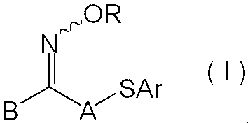
上記一価の非金属原子団としては、アルキル基、アリール基、アシル基、アルコキシカルボニル基、アリールオキシカルボニル基、複素環基、アルキルチオカルボニル基、アリールチオカルボニル基等が挙げられる。また、これらの基は、1以上の置換基を有していてもよい。また、前述した置換基は、更に他の置換基で置換されていてもよい。
置換基としてはハロゲン原子、アリールオキシ基、アルコキシカルボニル基又はアリールオキシカルボニル基、アシルオキシ基、アシル基、アルキル基、アリール基等が挙げられる。
具体的には、チエニル基、ベンゾ[b]チエニル基、ナフト[2,3-b]チエニル基、チアントレニル基、フリル基、ピラニル基、イソベンゾフラニル基、クロメニル基、キサンテニル基、フェノキサチイニル基、2H-ピロリル基、ピロリル基、イミダゾリル基、ピラゾリル基、ピリジル基、ピラジニル基、ピリミジニル基、ピリダジニル基、インドリジニル基、イソインドリル基、3H-インドリル基、インドリル基、1H-インダゾリル基、プリニル基、4H-キノリジニル基、イソキノリル基、キノリル基、フタラジニル基、ナフチリジニル基、キノキサニリル基、キナゾリニル基、シンノリニル基、プテリジニル基、4aH-カルバゾリル基、カルバゾリル基、β-カルボリニル基、フェナントリジニル基、アクリジニル基、ペリミジニル基、フェナントロリニル基、フェナジニル基、フェナルサジニル基、イソチアゾリル基、フェノチアジニル基、イソキサゾリル基、フラザニル基、フェノキサジニル基、イソクロマニル基、クロマニル基、ピロリジニル基、ピロリニル基、イミダゾリジニル基、イミダゾリニル基、ピラゾリジニル基、ピラゾリニル基、ピペリジル基、ピペラジニル基、インドリニル基、イソインドリニル基、キヌクリジニル基、モルホリニル基、及び、チオキサントリル基が例示できる。
下記の構造中、Y、X、及び、nは、それぞれ、後述する式(II)におけるY、X、及び、nと同義であり、好ましい例も同様である。
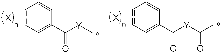
中でも、Aとしては、感度を高め、加熱経時による着色を抑制する点から、無置換のアルキレン基、アルキル基(例えば、メチル基、エチル基、tert-ブチル基、ドデシル基)で置換されたアルキレン基、アルケニル基(例えば、ビニル基、アリル基)で置換されたアルキレン基、アリール基(例えば、フェニル基、p-トリル基、キシリル基、クメニル基、ナフチル基、アンスリル基、フェナントリル基、スチリル基)で置換されたアルキレン基が好ましい。
中でも、感度を高め、加熱経時による着色を抑制する点から、置換又は無置換のフェニル基が好ましい。


上記Xで表される一価の置換基としては、アルキル基、アリール基、アルコキシ基、アリールオキシ基、アシルオキシ基、アシル基、アルコキシカルボニル基、アミノ基、複素環基、ハロゲン原子が挙げられる。また、これらの基は1以上の置換基を有していてもよい。置換基としては、前述した置換基が例示できる。また、前述した置換基は、更に他の置換基で置換されていてもよい。
また、式(II)におけるnは、0~5の整数を表し、0~2の整数が好ましい。

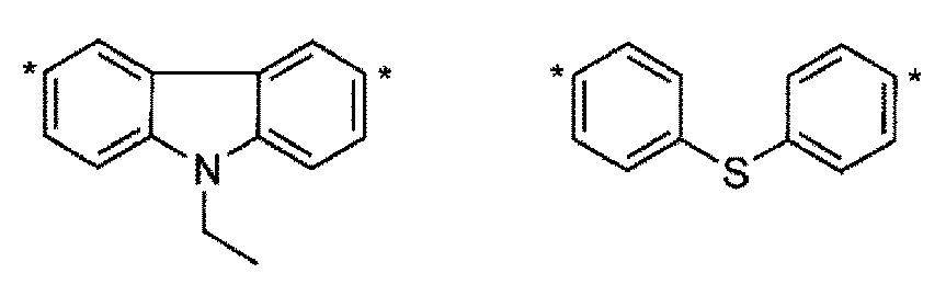
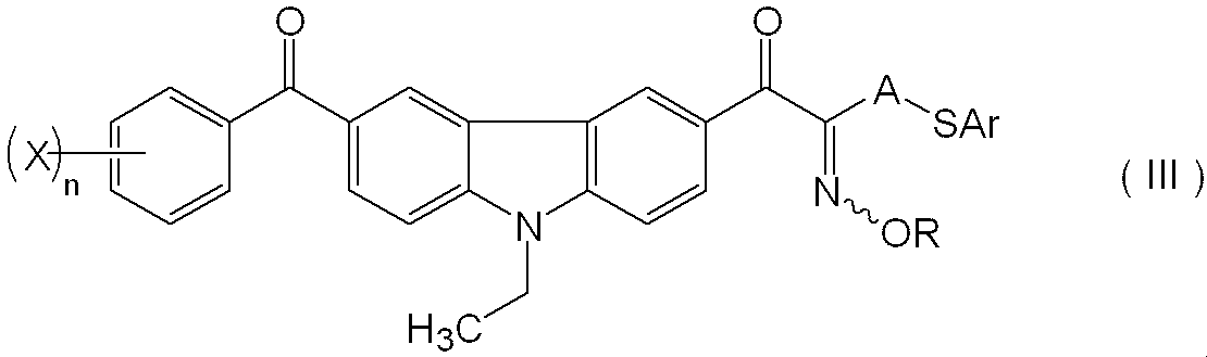
以下、好適に用いられるオキシム化合物の具体例(B-1)~(B-10)を以下に示すが、本発明はこれらに限定されるものではない。

化合物のモル吸光係数の測定には、公知の方法を用いることができるが、具体的には、例えば、紫外可視分光光度計(Varian社製Carry-5 spctrophotometer)にて、酢酸エチル溶媒を用い、0.01g/Lの濃度で測定することが好ましい。
光カチオン重合開始剤としては、例えば、紫外線等のエネルギー線を受けることにより光カチオン重合を開始させる物質を生成する化合物であればよく、オニウム塩が好ましく、芳香族オニウム塩がより好ましく、アリールスルホニウム塩及びアリールヨウドニウム塩が更に好ましい。
上記感光性低屈折率材料層は、(成分C)重合性官能基を有するポリマーを含有する。
成分Cのポリマー構造は、特に制限はなく、例えば、(メタ)アクリル樹脂、ウレタン樹脂、スチレン系樹脂、ビニル系樹脂が挙げられるが、(メタ)アクリル樹脂であることが好ましい。
成分Cは、単独重合体であっても、共重合体であってもよいが、(メタ)アクリレート化合物の単独重合体又は共重合体であることが好ましく、(メタ)アクリレート化合物の共重合体であることがより好ましい。
また、成分Cは、水現像又はアルカリ現像を容易に行うために、極性基(以下、「アルカリ可溶性基」ともいう。)を有していることが好ましい。
また、成分Cにおいて、重合性官能基や極性基は、ポリマーの主鎖に有していても、側鎖に有していてもよいが、側鎖に有していることが好ましい。
本発明における重合性官能基としては、特に制限されないが、ラジカル、カチオン又は加熱により重合反応する結合を有する基が好ましく、不飽和基(炭素-炭素不飽和二重結合など)、エポキシ基、オキセタニル基等を挙げることができ、エチレン性不飽和基又はアセチレン性不飽和基であることがより好ましい。
重合性官能基としては、(メタ)アクリロイル基、(メタ)アクリルアミド基、チオ(メタ)アクリロイル基、アリル基又はビニル基が好ましく、(メタ)アクリロイル基、(メタ)アクリルアミド基、アリル基又はビニル基がより好ましく、アリル基が特に好ましい。
極性基としては、酸基、アルコール性水酸基、ピロリドン基、アルキレンオキシド基などを挙げることができ、アルカリ現像液との反応によって塩を生じる基が好ましく、酸基がより好ましい。例えば、カルボキシル基、活性メチレン基、リン酸基、スルホン酸基などが挙げられる。
極性基としては、低屈折率性の観点から、カルボキシル基、活性メチレン基であることがより好ましく、カルボキシル基が特に好ましい。なお、活性メチレン基としては、-NH-C(O)-CH2-C(O)-RMで表される基であることが好ましく、RMはアルキル基又はアルコキシ基を表し、これら基はフッ素原子等の置換基を有していてもよい。RMは、炭素数1~6の、アルキル基又はアルコキシ基であることが好ましく、メチル基、トリフルオロメチル基又はメトキシ基であることがより好ましい。
これらの中でも、成分Cは、アリル基及びカルボキシル基を有するポリマーであることが好ましく、アリル基及びカルボキシル基を有する(メタ)アクリル樹脂であることがより好ましい。
上記反応性の異なる2種の重合性官能基の組み合わせとしては、(メタ)アクリルオキシ基と、エポキシ基、オキセタニル基、アリル基、ビニル基又はプロパルギル基との組み合わせが例示できる。
上記反応性の異なる2種の重合性官能基を用いたモノマーとしては、グリシジルアクリレート、3,4-エポキシシクロヘキシルメチルアクリレート、ビニルアクリレート、2-フェニルビニルアクリレート、1-プロペニルアクリレート、アリルアクリレート、プロパルギルアクリレート、グリシジルメタクリレート、3,4-エポキシシクロヘキシルメチルメタクリレート、ビニルメタクリレート、2-フェニルビニルメタクリレート、1-プロペニルメタクリレート、アリルメタクリレート、プロパルギルメタクリレート等が挙げられる。
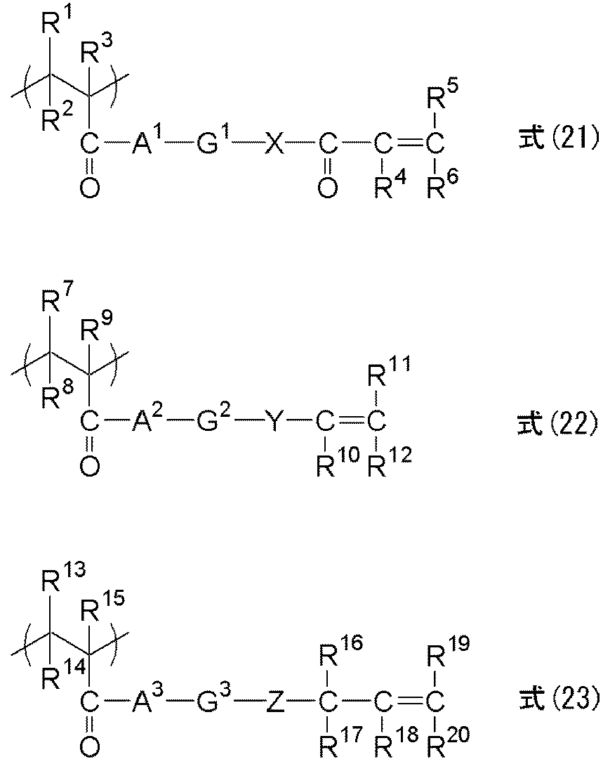
R4~R6はそれぞれ独立に、水素原子又は一価の置換基を表すが、R4としては、水素原子又は置換基を有してもよいアルキル基などが挙げられ、中でも、水素原子、メチル基、エチル基が好ましい。また、R5、R6は、それぞれ独立に、水素原子、ハロゲン原子、アルコキシカルボニル基、スルホ基、ニトロ基、シアノ基、置換基を有してもよいアルキル基、置換基を有してもよいアリール基、置換基を有してもよいアルコキシ基、置換基を有してもよいアリールオキシ基、置換基を有してもよいアルキルスルホニル基、置換基を有してもよいアリールスルホニル基などが挙げられ、中でも、水素原子、アルコキシカルボニル基、置換基を有してもよいアルキル基、置換基を有してもよいアリール基が好ましい。ここで、導入しうる置換基としては、メトキシカルボニル基、エトキシカルボニル基、イソプロピオキシカルボニル基、メチル基、エチル基、フェニル基等が挙げられる。
G1は、二価の連結基を表すが、置換基を有してもよいアルキレン基がより好ましい。より好ましくは、炭素数1~20の置換基を有してもよいアルキレン基、炭素数3~20の置換基を有してもよいシクロアルキレン基、炭素数6~20の置換基を有してもよい芳香族基などが挙げられ、中でも、置換基を有してもよい炭素数1~10の直鎖状あるいは分岐アルキレン基、炭素数3~10の置換基を有してもよいシクロアルキレン基、炭素数6~12の置換基を有してもよい芳香族基が強度、現像性等の性能上、好ましい。
R10~R12はそれぞれ独立に、水素原子又は一価の置換基を表す。R10~R12としては、具体的には例えば、水素原子、ハロゲン原子、ジアルキルアミノ基、アルコキシカルボニル基、スルホ基、ニトロ基、シアノ基、置換基を有してもよいアルキル基、置換基を有してもよいアリール基、置換基を有してもよいアルコキシ基、置換基を有してもよいアリールオキシ基、置換基を有してもよいアルキルスルホニル基、置換基を有してもよいアリールスルホニル基などが挙げられ、中でも、水素原子、アルコキシカルボニル基、置換基を有してもよいアルキル基、置換基を有してもよいアリール基が好ましい。
ここで、導入可能な置換基としては、式(21)において挙げたものが同様に例示される。
G2は、二価の連結基を表すが、置換基を有してもよいアルキレン基が好ましい。好ましくは、炭素数1~20の置換基を有してもよいアルキレン基、炭素数3~20の置換基を有してもよいシクロアルキレン基、炭素数6~20の置換基を有してもよい芳香族基などが挙げられ、中でも、置換基を有してもよい炭素数1~10の直鎖状或いは分岐アルキレン基、炭素数3~10の置換基を有してもよいシクロアルキレン基、炭素数6~12の置換基を有してもよい芳香族基が強度、現像性等の性能上、好ましい。
ここで、G2における置換基としては、水素原子がヘテロ原子に結合した基の中でも水酸基を除くもの、例えば、アミノ基、チオール基、カルボキシル基を含まないものが好ましい。
Yは、酸素原子、硫黄原子、-N(R23)-又は置換基を有してもよいフェニレン基を表す。ここで、R23としては、水素原子、置換基を有してもよいアルキル基などが挙げられる。
R16~R20はそれぞれ独立に、水素原子又は一価の置換基を表すが、R16~R20は、例えば、水素原子、ハロゲン原子、ジアルキルアミノ基、アルコキシカルボニル基、スルホ基、ニトロ基、シアノ基、置換基を有してもよいアルキル基、置換基を有してもよいアリール基、置換基を有してもよいアルコキシ基、置換基を有してもよいアリールオキシ基、置換基を有してもよいアルキルスルホニル基、置換基を有してもよいアリールスルホニル基などが挙げられ、中でも、水素原子、アルコキシカルボニル基、置換基を有してもよいアルキル基、置換基を有してもよいアリール基が好ましい。導入しうる置換基としては、式(21)において挙げたものが例示される。
A3は、酸素原子、硫黄原子又は-N(R21)-を表し、Zは、単結合又は酸素原子、硫黄原子、又は-N(R22)-を表す。R21、R22としては、式(21)におけるのと同様のものが挙げられる。Zは、単結合であることが好ましい。
ここで、G3における置換基としては、水素原子がヘテロ原子に結合した基の中でも水酸基を除くもの、例えば、アミノ基、チオール基、カルボキシル基を含まないものが好ましい。
酸基を有するモノマーとしては、例えば、(メタ)アクリル酸やイタコン酸等のカルボキシル基を有するモノマー、N-ヒドロキシフェニルマレイミド等のフェノール性水酸基を有するモノマー、無水マレイン酸、無水イタコン酸等のカルボン酸無水物基を有するモノマー等が挙げられるが、これらの中でも特に、(メタ)アクリル酸が好ましい。
重合後に酸基を付与しうるモノマーとしては、例えば、2-ヒドロキシエチル(メタ)アクリレート等の水酸基を有するモノマー、グリシジル(メタ)アクリレート等のエポキシ基を有するモノマー、2-イソシアナートエチル(メタ)アクリレート等のイソシアネート基を有するモノマー等が挙げられる。
重合後に酸基を付与しうるモノマーを用いる場合において、重合後に酸基を付与するための処理としては、ポリマー側鎖の極性基の一部を、ポリマー反応により変性する処理が挙げられる。
アルコール性水酸基を有するモノマーとしては、例えば、2-ヒドロキシエチルアクリレート、2-ヒドロキシプロピルアクリレート、3-ヒドロキシプロピルアクリレート、4-ヒドロキシブチルアクリレート、2-ヒドロキシエチルメタクリレート、2-ヒドロキシプロピルメタクリレート、3-ヒドロキシプロピルメタクリレート、4-ヒドロキシブチルメタクリレート等が挙げられる。
重合後にアルコール性水酸基を付与しうるモノマーとしては、例えば、グリシジル(メタ)アクリレート等のエポキシ基を有するモノマー等が挙げられる。
エポキシ基を有するモノマーとしては、例えば、グリシジルアクリレート、3,4-エポキシシクロヘキシルメチルアクリレート、グリシジルメタクリレート、3,4-エポキシシクロヘキシルメチルメタクリレート等が挙げられる。
重合後にエポキシ基を付与しうるモノマーとしては、例えば、例えば、2-ヒドロキシエチル(メタ)アクリレート等の水酸基を有するモノマー、2-イソシアナートエチル(メタ)アクリレート等のイソシアネート基を有するモノマー等が挙げられる。
これら極性基を導入するための単量体は、1種のみであってもよいし、2種以上であってもよい。
合成する際に用いられる溶媒としては、例えば、テトラヒドロフラン、エチレンジクロリド、シクロヘキサノン、メチルエチルケトン、アセトン、メタノール、エタノール、エチレングリコールモノメチルエーテル、エチレングリコールモノエチルエーテル、エチレングリコールモノメチルエーテルアセテート、2-メトキシエチルアセテート、ジエチレングリコールジメチルエーテル、1-メトキシ-2-プロパノール、1-メトキシ-2-プロピルアセテート、N,N-ジメチルホルムアミド、N,N-ジメチルアセトアミド、トルエン、酢酸エチル、乳酸メチル、乳酸エチル、ジメチルスルホキシド、水等が挙げられる。
これらの溶媒は単独で又は2種以上混合して用いられる。
これらのラジカル重合開始剤は、モノマー100質量部に対して、1質量部~20質量部使用されることが好ましい。
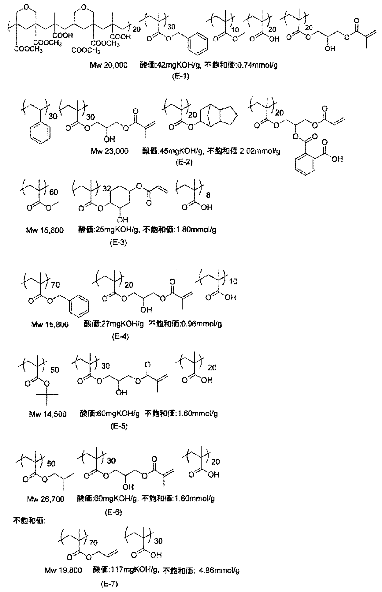
成分Cの重合性官能基がエチレン性不飽和基である場合、光感度向上の観点から、成分Cの不飽和価は、0.1mmol/g以上が好ましく、更に0.5mmol/g以上が好ましく、1.0mmol/g以上が最も好ましい。また、成分Cの不飽和価は、10mmol/g以下が好ましい。ここで、不飽和価とは、バインダーポリマー1gあたりの不飽和結合のミリモル数を意味する。
成分Cの不飽和当量を0.1mmol/g以上とすることにより、つまり、この樹脂中においてエチレン性不飽和結合数が増加することにより、光重合性、感度が向上し、更に、この重合性向上により、支持体などの固体表面への密着性や含有する中空又は多孔質粒子の固定化性も向上し、結果として、現像におけるパターン膜中の中空又は多孔質粒子の欠損が少なく、テーパー状~矩形状の断面形状を有するパターンが得られ易い傾向となり、好ましい。
上記感光性低屈折率材料層における成分Cの含有量としては、感光性低屈折率材料層の全質量に対して、0.01~25質量%の割合で配合することが耐擦傷性及び塗布性の観点から好ましく、3~20質量%の範囲で添加することが更に好ましい。成分Cの含有量が3~20質量%の範囲内にあると、中空又は多孔質粒子の低屈折率性を活かしつつ、膜に硬度を持たせることができる。
本発明の感光性転写材料における感光性低屈折率材料層は、(成分D)モノマー(「重合性化合物」ともいう。)を含有する。
ただし、成分Dは、(成分C)重合性官能基を有するポリマー以外の化合物であり、分子量1,500未満の化合物であり、分子量1,000未満の化合物であることが好ましく、分子量800未満の化合物であることがより好ましい。また、成分Dは、分子量50以上の化合物であることが好ましい。
以下、モノマーについて説明する。
また、モノマーは、エチレン性不飽和結合を分子末端に有する化合物であることが好ましい。
これらの具体的な化合物としては、特開2009-288705号公報の段落0095~0108に記載されている化合物を本発明においても好適に用いることができる。
また、モノマーとしては、前述した成分Cの製造に用いることができるエチレン性不飽和化合物も好適に用いることができる。

式(MO-1)~(MO-5)で表されるモノマーの具体例としては、特開2007-269779号公報の段落0248~0251に記載されている化合物を本発明においても好適に用いることができる。
また、フッ素原子を有するモノマーとしては、フッ素原子を有する(メタ)アクリレート化合物が好ましく、フッ素原子を有する多官能(メタ)アクリレート化合物がより好ましい。
フッ素原子を有する多官能モノマーとしては、下記式(Df)で表される化合物が好ましい。

式(Df)におけるR1は、n価のペルフルオロアルキル基又は4級炭素であることが好ましく、4級炭素であることがより好ましい。
式(Df)におけるR2は、n価のペルフルオロアルキル基又はフッ素原子であることが好ましく、フッ素原子であることがより好ましい。
式(Df)におけるmは、1であることが好ましい。
式(Df)におけるnは、3~20の整数であることが好ましく、3~10の整数であることがより好ましく、3~6の整数であることが更に好ましく、4であることが特に好ましい。
式(Df)におけるGは、(メタ)アクリル基、ビニル基又はアリル基であることが好ましく、(メタ)アクリル基であることがより好ましい。


上記感光性低屈折率材料層における成分Dの含有量は、上記感光性低屈折率材料層の全質量に対して0.1~30質量%が好ましく、0.2~20質量%が更に好ましく、0.3~15質量%が特に好ましい。
上記感光性低屈折率材料層は、本発明の効果を損なわない限りにおいて、必要に応じて、以下に詳述する任意成分を更に含有してもよい。
以下、上記感光性低屈折率材料層が含有しうる任意成分について説明する。
上記感光性低屈折率材料層は、界面活性剤を含有することが好ましい。
界面活性剤としては、フッ素系界面活性剤、ノニオン系界面活性剤、カチオン系界面活性剤、アニオン系界面活性剤、シリコーン系界面活性剤などの各種界面活性剤を使用できる。
上記感光性低屈折率材料層における界面活性剤の添加量は、上記感光性低屈折率材料層の全質量100質量部に対して、10質量部以下であることが好ましく、0.001~10質量部であることがより好ましく、0.01~3質量部であることが更に好ましい。
上記感光性低屈折率材料層は、中空又は多孔質粒子の分散性を向上させる観点から、更に、(成分F)分散剤を含有することが好ましい。
分散剤としては、ポリアミドアミンとその塩、ポリカルボン酸とその塩、高分子量不飽和酸エステル、変性ポリウレタン、変性ポリエステル、変性ポリ(メタ)アクリレート、(メタ)アクリル系共重合体、ナフタレンスルホン酸ホルマリン縮合物などの分散樹脂や、ポリオキシエチレンアルキルリン酸エステル、ポリオキシエチレンアルキルアミン、アルカノールアミン等の化合物を挙げることができるが、樹脂であることが好ましい(以下、これを「分散樹脂」ともいう。)。なお、成分Fは、重合性基を有しないものとする。
分散樹脂は、その構造から更に直鎖状高分子、末端変性型高分子、グラフト型高分子、ブロック型高分子に分類することができる。
また、分散樹脂は、前述した成分Cにおける式(E-1)で表される化合物を共重合モノマーとして使用することにより得られる樹脂であってもよい。
上記感光性低屈折率材料層における分散剤の含有量は、中空又は多孔質粒子の含有量に対して、1~100質量%であることが好ましく、5~80質量%がより好ましく、10~60質量%であることが更に好ましい。
具体的には、分散剤が分散樹脂である場合、その使用量は、中空又は多孔質粒子の含有量に対して、5~100質量%であることが好ましく、10~80質量%であることがより好ましい。
上記感光性低屈折率材料層は、光重合開始剤等のラジカル発生効率の向上、感光波長の長波長化の目的で、増感剤を含有していてもよい。
本発明に用いることができる増感剤としては、上記した光重合開始剤に対し、電子移動機構又はエネルギー移動機構で増感させるものが好ましい。
増感剤を含有する場合、上記感光性低屈折率材料層中における増感剤の含有量は、深部への光吸収効率と開始分解効率の観点から、上記感光性低屈折率材料層の全質量に対して、0.1~20質量%であることが好ましく、0.5~15質量%がより好ましい。
増感剤は、1種単独で用いてもよいし、2種以上を併用してもよい。
上記感光性低屈折率材料層においては、上記感光性低屈折率材料層の製造中あるいは感光性転写材料の保存中において、モノマーの不要な熱重合を阻止するために少量の重合禁止剤を添加してもよい。
重合禁止剤としては、ハイドロキノン、p-メトキシフェノール、ジ-t-ブチル-p-クレゾール、ピロガロール、t-ブチルカテコール、ベンゾキノン、4,4’-チオビス(3-メチル-6-t-ブチルフェノール)、2,2’-メチレンビス(4-メチル-6-t-ブチルフェノール)、N-ニトロソフェニルヒドロキシアミン第一セリウム塩等が挙げられる。
また、必要に応じて、酸素による重合阻害を防止するためにベヘン酸やベヘン酸アミドのような高級脂肪酸誘導体等を添加して、塗布後の乾燥の過程で塗布膜の表面に偏在させてもよい。上記感光性低屈折率材料層が高級脂肪酸誘導体を含有する場合、高級脂肪酸誘導体の添加量は、上記感光性低屈折率材料層の全質量に対し、0.5~10質量%であることが好ましい。
上記感光性低屈折率材料層は、本発明の目的を損なわない範囲で、いかなる密着促進剤を含有していてもよい。
密着促進剤としては、例えば、3-グリシジロキシプロピルトリメトキシシラン、1-メタクリロキシプロピルメチルジメトキシシラン、3-アミノグリシジロキシプロピルトリエトキシシラン、3-グリシジロキシプロピルメチルジメトキシシラン、3-アミノプロピルトリメトキシシランなどが挙げられる。他には、特開2008-243945号公報の段落0048に記載の化合物を用いることができる。
密着促進剤を含有する場合、密着促進剤の好ましい使用量は、特に制限されないが、上記感光性低屈折率材料層の全質量に対して、10質量%以下であることが好ましく、0.005~5質量%であることがより好ましい。
更に、上記感光性低屈折率材料層は、硬化皮膜の物性を改良するために無機充填剤や、可塑剤等の公知の添加剤を含有していてもよい。
可塑剤としては、例えば、ジオクチルフタレート、ジドデシルフタレート、トリエチレングリコールジカプリレート、ジメチルグリコールフタレート、トリクレジルホスフェート、ジオクチルアジペート、ジブチルセバケート、トリアセチルグリセリン等が挙げられる。可塑剤を使用した場合、成分C及び成分Dの合計質量に対し10質量%以下添加することが好ましい。
有機溶剤は、各成分の溶解性や感光性組成物の塗布性を満足すれば、基本的には特に制限はなく、特に、バインダーの溶解性、塗布性及び安全性を考慮して選ばれることが好ましい。有機溶剤としては、例えば、特開2008-32803号公報の段落0187に記載の各種溶剤が挙げられる。
ケトン類としては、例えば、メチルエチルケトン、シクロヘキサノン、2-ヘプタノン、3-ヘプタノン等が挙げられる。
芳香族炭化水素類としては、例えば、トルエン、キシレン等が好適に挙げられる。
感光性低屈折率材料層の形成方法は、特に限定されないが、例えば、少なくとも成分A~成分D及び有機溶剤を含有する感光性樹脂組成物をスピンコーティング法、ローラーコーティング法、ディップコーティング法、スキャン法、スプレー法、バー塗布法、インクジェット法等の任意の方法により、支持体に塗布した後、有機溶剤を必要に応じて加熱処理で除去して塗膜(感光性低屈折率材料層)を形成し、プリベーク処理を施すことにより形成することができる。
洗浄液としては、アルキレングリコールモノアルキルエーテルカルボキシレート、又はアルキレングリコールモノアルキルエーテルを用いることが好ましい。
洗浄液として用いうるこれら溶剤は、単独で用いても2種以上を混合して用いてもよい。
溶剤を2種以上混合する場合、水酸基を有する溶剤と水酸基を有しない溶剤とを混合してなる混合溶剤が好ましい。水酸基を有する溶剤と水酸基を有しない溶剤との質量比は、好ましくは1/99~99/1、より好ましくは10/90~90/10、更に好ましくは20/80~80/20である。混合溶剤としては、プロピレングリコールモノメチルエーテルアセテート(PGMEA)とプロピレングリコールモノメチルエーテル(PGME)との混合溶剤で、その比率が60/40であることが特に好ましい。
なお、感光性樹脂組成物に対する洗浄液の浸透性を向上させるために、洗浄液には、感光性樹脂組成物が含有しうる界面活性剤として前掲した界面活性剤を添加してもよい。
本発明の感光性転写材料は、支持体上に少なくとも上記感光性低屈折率材料層を設けたものであり、必要に応じて、熱可塑性樹脂層、中間層、及び/又は、保護層等を設けることができる。
また、上記感光性低屈折率材料層は、支持体上に少なくとも設けられていればよく、支持体と直接接していても、他の層を介して設けられていてもよく、また、支持体上の全面に設けられていても、一部に設けられていてもよい。
上記感光性低屈折率材料層の膜厚は、0.01~2.0μmの範囲が好ましく、0.1~1.5μmの範囲がより好ましく、0.2~1.0μmの範囲が更に好ましい。
図1に示す感光性転写材料10は、支持体12上に、熱可塑性樹脂層14、中間層16、感光性低屈折率材料層18及び保護層20がこの順で設けられており、支持体12の反対の面には、帯電防止層22が設けられている。
感光性転写材料10を使用して転写する際には、保護層20は事前に除去される。
また、熱可塑性樹脂層14及び中間層16は、感光性低屈折率材料層18を容易に露光できるようにするため、活性光線透過性の層であることが好ましい。
本発明の感光性転写材料における支持体としては、特に制限はなく、ポリエステル、ポリスチレン等の公知の支持体を用いることができる。
本発明の感光性転写材料における支持体は、基板等の所望の被転写体に感光性低屈折率材料層を転写した後には、不要なものであり、「仮支持体」ともいう。上記支持体は、感光性低屈折率材料層の転写と同時又は転写後に除去されることが好ましい。
中でも、支持体としては、コスト、耐熱性、寸法安定性の観点から、ポリエチレンテレフタレートフィルムが好ましい。
上記支持体の厚みは、15~200μmであることが好ましく、30~150μmがより好ましい。上記支持体の厚みが上記範囲内にあると、ラミネーション工程時に熱によりトタン板状のしわが発生するのを効果的に抑制することができ、コスト上も有利である。
また、支持体と感光性低屈折率材料層との間又は支持体と中間層との間に、熱可塑性樹脂層を設けることが好ましい。上記熱可塑性樹脂層は、感光性低屈折率材料層の転写と同時又は転写後に除去されることが好ましい。また、上記熱可塑性樹脂層は、アルカリ可溶性であることが好ましい。
上記熱可塑性樹脂層は、下地表面の凹凸(既に形成されている画像などによる凹凸等も含む。)を吸収することができるようにクッション材としての役割を担うものであるため、当該凹凸に応じて変形しうる性質を有していることが好ましい。
また、これらの熱可塑性樹脂のうち、軟化点が80℃以下のものが好ましい。また、軟化点は30℃以上であることが好ましい。
これらの樹脂の具体例としては、特公昭54-34327号、特公昭55-38961号、特公昭58-12577号、特公昭54-25957号、特開昭61-134756号、特公昭59-44615号、特開昭54-92723号、特開昭54-99418号、特開昭54-137085号、特開昭57-20732号、特開昭58-93046号、特開昭59-97135号、特開昭60-159743号、特開昭60-247638号、特開昭60-208748号、特開昭60-214354号、特開昭60-230135号、特開昭60-258539号、特開昭61-169829号、特開昭61-213213号、特開昭63-147159号、特開昭63-213837号、特開昭63-266448号、特開昭64-55551号、特開昭64-55550号、特開平2-191955号、特開平2-199403号、特開平2-199404号、特開平2-208602号、特開平5-241340号の各公報に記載されているアルカリ水溶液に可溶な樹脂を挙げることができる。
好ましい可塑剤の具体例としては、ポリプロピレングリコール、ポリエチレングリコール、ジオクチルフタレート、ジヘプチルフタレート、ジブチルフタレート、トリクレジルフォスフェート、クレジルジフェニルフォスフェート、ビフェニルジフェニルフォスフェート、ポリエチレングリコールモノ(メタ)アクリレート、ポリエチレングリコールジ(メタ)アクリレート、ポリプロピレングリコールモノ(メタ)アクリレート、ポリプロピレングリコールジ(メタ)アクリレート、エポキシ樹脂とポリエチレングリコールモノ(メタ)アクリレートとの付加反応生成物、有機ジイソシアナートとポリエチレングリコールモノ(メタ)アクリレートとの付加反応生成物、有機ジイソシアナートとポリプロピレングリコールモノ(メタ)アクリレートとの付加反応生成物、ビスフェノールAとポリエチレングリコールモノ(メタ)アクリレートとの縮合反応生成物等を挙げることができる。
上記熱可塑性樹脂層中の可塑剤の量は、上記熱可塑性樹脂の全質量に対して、200質量%以下であることが好ましく、20~100質量%であることがより好ましい。
また、上限については、現像性、製造適性から、100μm以下であることが好ましく、50μm以下であることがより好ましい。
上記溶媒としては、例えば、メチルエチルケトン、シクロヘキサノン、プロピレングリコールモノメチルエーテルアセテート、n-プロパノール、i-プロパノール等が挙げられる。
本発明の感光性転写材料は、支持体と感光性低屈折率材料層との間に中間層を設けてもよい。上記中間層は、感光性低屈折率材料層の転写と同時又は転写後に除去されることが好ましい。
中間層を構成する樹脂としては、アルカリ可溶であれば特に制限はない。
中間層を構成する樹脂の例としては、ポリビニルアルコール系樹脂、ポリビニルピロリドン系樹脂、セルロース系樹脂、アクリルアミド系樹脂、ポリエチレンオキサイド系樹脂、ゼラチン、ビニルエーテル系樹脂、ポリアミド樹脂、及び、これらの共重合体を挙げることができる。
また、ポリエステル樹脂のように通常はアルカリ可溶性でない樹脂にカルボキシル基やスルホン酸基を持つモノマーを共重合した樹脂も好ましく用いることができる。
これらの中で好ましいものはポリビニルアルコールである。
ポリビニルアルコールとしては、鹸化度が80%以上のものが好ましく、83~98%のものがより好ましい。
なお、上記中間層には、必要に応じて、界面活性剤などの添加剤を添加することができる。
中間層の塗布溶媒としては、上記の樹脂が溶解すれば特にその他の制限はないが、中でも水が好ましく、また水に前述の水混和性有機溶剤を混合した混合溶媒も好ましい。
好ましい塗布溶媒の具体例としては、例えば、水、水/メタノール=90/10、水/メタノール=70/30、水/メタノール=55/45、水/エタノール=70/30、水/1-プロパノール=70/30、水/アセトン=90/10、水/メチルエチルケトン=95/5(ただし、比は質量比を表す。)等が挙げられる。
本発明の感光性転写材料は、必要に応じて、帯電防止層を有していてもよい。帯電防止層は、支持体の上記感光性低屈折率材料層が設けられている面とは反対の面に設けられることが好ましい。
帯電防止層としては、例えば、特開平11-149008号公報に記載されている導電性層が挙げられる。
また、本発明の感光性転写材料は、感光性低屈折率材料層への汚れ等の付着を防ぐため、必要に応じて、保護層を有していてもよい。保護層は、上記感光性低屈折率材料層上に設けられることが好ましい。
保護層としては、公知の材質の層であればよいが、樹脂フィルムが好ましく挙げられる。樹脂フィルムの材質としては、ポリプロピレンやポリビニルアルコール、ポリビニルピロリドンがより好ましく挙げられる。
また、本発明の感光性転写材料は、必要に応じて、前述した以外の公知の層を有していてもよい。
本発明の感光性転写材料を作製する方法としては、例えば、支持体に、少なくとも成分A~成分Dを含有する感光性樹脂組成物を、例えば、スピナー、ホワイラー、ローラーコーター、カーテンコーター、ナイフコーター、ワイヤーバーコーター、エクストルーダー等の塗布機を用いて塗布・乾燥させることにより形成する方法が好ましく挙げられる。
アルカリ可溶性熱可塑性樹脂の層を設ける場合にも同様にして形成することができる。
上記感光性樹脂組成物は、有機溶剤を含有することが好ましい。上記態様であると、薄膜でかつ膜厚均一性の高い塗布膜を作製することができる。
本発明の感光性低屈折率転写層を有する基板は、本発明の感光性転写材料から上記感光性低屈折率材料層を転写した感光性低屈折率転写層を有する基板である。
上記感光性低屈折率転写層を有する基板の作製方法としては、特に制限はないが、基板、好ましくは光透過性基板の上に、本発明の感光性転写材料を、感光性転写材料の感光性低屈折率材料層が接触するように配置して積層し、次に、感光性転写材料と基板との積層体から支持体を剥離し、その後、上記感光性低屈折率転写層を露光し、現像して感光性低屈折率転写層を有する基板を形成する方法が好ましく挙げられる。
この感光性低屈折率転写層を有する基板の製造方法は、煩雑な工程を行うことを必要とせず、低コストである。
本発明の感光性低屈折率転写層の製造方法は、本発明の感光性転写材料を用いた方法であれば、特に制限はないが、本発明の感光性転写材料を準備する工程(以下、「準備工程」ともいう。)、被転写部材と上記感光性低屈折率材料層とが接するように上記感光性転写材料を上記被転写部材に積層する工程(以下、「積層工程」ともいう。)、及び、上記感光性転写材料の支持体を剥離する工程(以下、「剥離工程」ともいう。)、を含むことが好ましい。
上記準備工程は、前述した方法により本発明の感光性転写材料を作製すればよい。
上記積層工程における被転写部材としては、リフレクター上や導光板上、ガラス基板、又は、これらの表面に各種金属層が形成された基板や、プラスチックフィルムが形成された基板、拡散シート、プリズムシート、マイクロレンズユニットなどの光学シートを挙げることができる。中でも、拡散シート、プリズムシート、マイクロレンズユニットなどの光学シートが好ましく、光学シートの間に本発明の転写材料を積層してバックライトモジュールを製造することがより好ましい。
上記剥離工程における支持体の剥離方法としては、特に制限はなく、公知の方法により剥離すればよい。
また、本発明の感光性低屈折率転写層の製造方法は、他の公知の工程を含んでいてもよい。
本発明の永久膜の形成方法は、本発明の感光性転写材料を用いた方法であれば、特に制限はないが、本発明の感光性転写材料を準備する工程(「準備工程」ともいう。)、被転写部材と上記感光性低屈折率材料層とが接するように上記感光性転写材料を上記被転写部材に積層する工程(「積層工程」ともいう。)、上記感光性転写材料の支持体を剥離する工程(「剥離工程」ともいう。)、及び、転写された上記感光性低屈折率材料層(感光性低屈折率転写層)を露光する工程(「露光工程」ともいう。)、を含むことが好ましい。
本発明の永久膜の形成方法における準備工程、積層工程及び剥離工程の好ましい態様は、前述した本発明の感光性低屈折率転写層の製造方法における準備工程、積層工程及び剥離工程の好ましい態様と同様である。
上記露光工程における露光に活性光線又は放射線としては、赤外光、g線、h線、i線、KrF光、ArF光、X線、電子線等を挙げることができる。露光量、感度、解像度の観点から、i線、KrF光、ArF光、電子線が好ましく、更に汎用性の観点から、i線、KrF光が最も好ましい。照射光にi線を用いる場合、100mJ/cm2~10000mJ/cm2の露光量で照射することが好ましい。KrF光を用いる場合は、30mJ/cm2~300mJ/cm2の露光量で照射することが好ましい。
また、露光した層は、必要に応じて、ホットプレートやオーブンを用いて、加熱処理を行ってもよい。加熱条件としては、特に制限はないが、例えば、70℃~180℃で、0.5~15分間が好ましい。
露光工程では、光重合開始剤が分解し重合開始種が発生する。発生した重合開始種により成分Cの重合性官能基や成分D等が重合し、露光した部分が硬化され、永久膜が得られる。
露光光源としては、低圧水銀灯、高圧水銀灯、超高圧水銀灯、ケミカルランプ、LED光源、エキシマレーザー発生装置などを用いることができる。また、必要に応じて長波長カットフィルター、短波長カットフィルター、バンドパスフィルターのような分光フィルターを通して照射光を調整することもできる。
露光装置としては、ミラープロジェクションアライナー、ステッパー、スキャナー、プロキシミティ、コンタクト、マイクロレンズアレイ、レーザー露光など各種方式の露光機を用いることができる。
上記現像工程では、硬化していない未露光部分を現像液により除去して現像し、ネガ画像(永久膜)を形成する。
現像工程で使用する現像液には、塩基性化合物が含まれることが好ましい。塩基性化合物としては、例えば、水酸化リチウム、水酸化ナトリウム、水酸化カリウムなどのアルカリ金属水酸化物類;炭酸ナトリウム、炭酸カリウムなどのアルカリ金属炭酸塩類;重炭酸ナトリウム、重炭酸カリウムなどのアルカリ金属重炭酸塩類;テトラメチルアンモニウムヒドロキシド、テトラエチルアンモニウムヒドロキシド、コリンヒドロキシド等のアンモニウムヒドロキシド類;ケイ酸ナトリウム、メタケイ酸ナトリウムなどの水溶液を使用することができる。また、上記アルカリ類の水溶液にメタノールやエタノールなどの水溶性有機溶剤や界面活性剤を適当量添加した水溶液を現像液として使用することもできる。
好ましい現像液として、テトラエチルアンモニウムヒドロキシドの0.4質量%水溶液、0.5質量%水溶液、0.7質量%水溶液、又は、2.38質量%水溶液を挙げることができる。
現像液のpHは、好ましくは10.0~14.0である。
現像時間は、好ましくは30~500秒間であり、また、現像の手法は液盛り法、ディップ法等のいずれでもよい。現像後は、流水洗浄を30~300秒間行い、所望のパターンを形成させることができる。
現像の後に、リンス工程を行うこともできる。リンス工程では、現像後の基板を純水などで洗うことで、付着している現像液除去、現像残渣除去を行う。リンス方法は公知の方法を用いることができる。例えばシャワーリンスやディップリンスなどを挙げることができる。
後加熱及び/又は後露光工程としては、加熱処理(焼成)することが好ましい。例えば、樹脂に残存する成分Cの重合性官能基や成分Dのエチレン性不飽和基等の後加熱時の重合反応が利用できる。この後加熱処理の条件は、好ましくは100~600℃、より好ましくは200~500℃、特に好ましくは200℃~450℃で、好ましくは1分~3時間、より好ましくは1分~2時間、特に好ましくは1分~1時間の範囲である。後加熱処理は数回に分けて行ってもよい。後加熱工程は、現像された上記感光性低屈折率材料層を、ホットプレート、オーブン等の加熱装置により加熱することにより行うことができる。
この後加熱工程において、加熱温度は、120~250℃が好ましく、160~230℃がより好ましい。また加熱時間は、加熱手段により異なるが、ホットプレート上で加熱する場合、5~30分間が好ましく、オーブン中で加熱する場合、30~90分間が好ましい。
また、後加熱工程に際しては、2回以上加熱するステップベーク法等を採用することもできる。
高エネルギー線として電子線を使用した場合のエネルギーは、0.1~50keVが好ましく、0.2~30keVがより好ましく、0.5~20keVが特に好ましい。電子線の総ドーズ量は、0.01~5μC/cm2が好ましく、0.01~2μC/cm2がより好ましく、0.01~1μC/cm2が特に好ましい。電子線を照射する際の基板温度は、0~500℃が好ましく、20~450℃がより好ましく、20~400℃が特に好ましい。圧力は、0~133kPaが好ましく、0~60kPaがより好ましく、0~20kPaが特に好ましい。
重合体の酸化を防止するという観点から、基板周囲の雰囲気はAr、He、窒素などの不活性雰囲気を用いることが好ましい。また、電子線との相互作用で発生するプラズマ、電磁波、化学種との反応を目的に酸素、炭化水素、アンモニアなどのガスを添加してもよい。電子線照射は複数回行ってもよく、この場合は電子線照射条件を毎回同じにする必要はなく、毎回異なる条件で行ってもよい。
まず、図2(a)に示すように、感光性転写材料100は、支持体102上に、熱可塑性樹脂層104、中間層106及び感光性低屈折率材料層108がこの順で設けられており、感光性低屈折率材料層108と被転写部材110とが直接接するように、2つのローラー112を接着させる。
続いて、支持体102を剥離し(不図示)、図2(b)に示すように、熱可塑性樹脂層104側から活性光線114を照射し、感光性低屈折率材料層108を露光する。
図2(c)~(d)に示すように、熱可塑性樹脂層104、中間層106及び感光性低屈折率材料層108の未露光部分を現像液により除去し、現像する。熱可塑性樹脂層104、中間層106及び感光性低屈折率材料層108の未露光部分の除去は、それぞれ逐次に行っても、2以上の層を同時に行ってもよい。
続いて、図2(e)に示すように、現像された感光性低屈折率材料層108の表面をブラシ116によりこすり、現像残渣を除去してもよい。
本発明の光学デバイスの製造方法は、本発明の感光性転写材料を準備する工程、バックライトモジュール基板とカラーフィルター基板との間の少なくとも1層として、上記感光性低屈折率材料層と上記バックライトモジュール基板又は上記カラーフィルター基板とが接するように上記感光性転写材料を積層する工程、及び、上記感光性転写材料の支持体を剥離する工程、を含む。
本発明の光学デバイスの製造方法における各工程の好ましい態様は、本発明の感光性転写材料を用いた方法であれば、特に制限はないが、感光性転写材料の積層時に、バックライトモジュール基板とカラーフィルター基板との間の少なくとも1層として、上記感光性低屈折率材料層と上記バックライトモジュール基板又は上記カラーフィルター基板とが接するように上記感光性転写材料を積層すること以外は、前述した本発明の感光性低屈折率転写層の製造方法における各工程の好ましい態様と同様である。
上記光学デバイスとしては、例えば、液晶ディスプレイ等が挙げられ、特に、バックライトモジュール基板及びカラーフィルター基板を備えたバックライトユニットが好適に挙げられる。
本発明の光学デバイスの製造方法における露光工程の好ましい態様は、前述した本発明の永久膜の形成方法における露光工程の好ましい態様と同様である。
本発明の光学デバイスの製造方法は、露光した上記感光性低屈折率材料層を現像する工程(「現像工程」ともいう。)を更に含んでいてもよい。
本発明の光学デバイスの製造方法における現像工程の好ましい態様は、前述した本発明の永久膜の形成方法における現像工程の好ましい態様と同様である。
本発明の光学デバイスの製造方法は、現像工程後、必要に応じて、現像された上記感光性低屈折率材料層を加熱及び/又は露光する工程(「後加熱及び/又は後露光工程」ともいう。)を更に含んでいてもよい。
本発明の光学デバイスの製造方法における後加熱及び/又は後露光工程の好ましい態様は、前述した本発明の永久膜の形成方法における後加熱及び/又は後露光工程の好ましい態様と同様である。
また、本発明の光学デバイスの製造方法は、他の公知の工程を含んでいてもよい。
図3は、本発明の光学デバイスの製造方法により製造されるバックライトユニットの一例を示す断面図である。
反射板202に本発明の感光性転写材料を接触するように重ね合わせ、ラミネーター((株)日立インダストリイズ製(LamicII型))を用いて両者を貼り合わせた後に、感光性転写材料から支持体(ポリエチレンテレフタレートフィルム)を剥離し、その後に熱可塑性樹脂層を除去することにより(不図示)、感光性低屈折率材料層を積層させた反射板202が得られる。導光板204の端辺に光源としてランプ206とランプ反射板208とを備えるランプユニット210を設け、導光板204と感光性低屈折率材料層とを積層させた反射板202を、感光性低屈折率材料層と導光板204とが接触するように貼り合わせ、感光性低屈折率材料層を露光し硬化して、ランプユニット210と反射板202を具備する導光板204が得られる。同様に、拡散シート212、プリズムシート214に本発明の感光性転写材料から感光性低屈折率材料層をそれぞれ転写して積層させ導光板204に貼り合わせ、感光性転写材料から転写した感光性低屈折率材料層を硬化させて低屈折率層216とし、バックライトユニット200が得られる。
光学デバイスである得られたバックライトユニット200には、図3の下から反射板202、低屈折率層216、導光板204、低屈折率層216、拡散シート212、低屈折率層216、プリズムシート214、プリズムシート214の形状に合った低屈折率層216が当該順で積層されており、導光板204の端辺には、ランプ206とランプ反射板208とを備えたランプユニット210が設けられている。
また、本発明の光学デバイスの製造方法により製造されるバックライトユニットは、図3における4つの低屈折率層216のうち、少なくとも1層が本発明の感光性転写材料により形成されたものであればよい。本発明の感光性転写材料は、図3に示すように、バックライトユニット等の光学デバイスにおける種々の層に用いることができる。
<感光性低屈折率材料層用塗布液の調製>
下記組成を混合して、感光性低屈折率材料層用塗布液を調製した。なお、表1に記載の各成分の使用量を表す数値の単位は、質量部である。

PGMEA:プロピレングリコールモノメチルエーテルアセテート
Allyl/MAA=80/20:アリルメタクリレートとメタクリル酸とのモル比80:20の共重合体(下記に示すポリマー)、分子量Mw=30,000
BzMA/MAA=80/20:ベンジルメタクリレートとメタクリル酸とのモル比80:20の共重合体(下記に示すポリマー)、分子量Mw=30,000
DPHA:ジペンタエリスリトールヘキサアクリレート(新中村化学工業(株)製)
FFA-1:下記に示すモノマーFFA-1の40質量%PGMEA溶液
IRGACURE OXE-01:下記に示す化合物
F-554:パーフルオロアルキル基含有ノニオン界面活性剤の2質量%PGMEA溶液、DIC(株)製
スルーリア4320:中空シリカ粒子の20質量%メチルイソブチルケトン(MIBK)分散液、日揮触媒化成(株)製、平均一次粒子径60nm
SiO2粒子:中空又は多孔質でないシリカ粒子の30質量%MIBK分散液、日産化学工業(株)製MIBK-ST、粒子径10~20nm


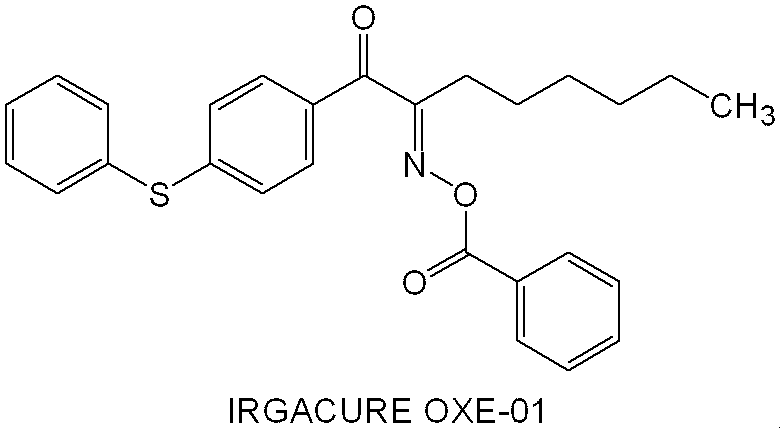
2軸延伸した75μm厚みのポリエチレンテレフタレートフィルム支持体表面に、スリット状ノズルを有するガラス基板用コーター(エフ・エー・エス・ジャパン社製、商品名:MH-1600)を用いて、下記のように調製した熱可塑性樹脂層用塗布液を厚みが15μmになるように塗布して100℃で5分間乾燥し、熱可塑性樹脂層を形成した。次いで、この上に中間層用塗布液を乾燥膜厚が1.5μmになるように塗布して、100℃で5分間乾燥し、中間層を形成した。更にこの上に、感光性低屈折率材料層用塗布液を、乾燥膜厚2.0μmになるよう塗布して100℃で5分間乾燥し、感光性低屈折率材料層を形成し、感光性転写材料を作製した。
下記組成を混合して熱可塑性樹脂層用塗布液を調製した。
・メチルメタクリレート/2-エチルヘキシルアクリレート/ベンジルメタクリレート/メタクリル酸(55/11.7/4.5/28.8)の共重合体(分子量80,000):58部
・スチレン/アクリル酸=63/37の共重合体(分子量7,000):136部
・2,2-ビス[4-(メタクリロキシポリエトキシ)フェニル]プロパン(新中村化学工業(株)製、多官能アクリレート):90部
・フッ素系界面活性剤(商品名:F780F、大日本インキ化学工業(株)製):1部
・メチルエチルケトン:541部
・1-メトキシ-2-プロパノール:63部
・メチルアルコール:111部
下記組成を混合して中間層用塗布液を調製した。
・ポリビニルアルコール(商品名:PVA205、(株)クラレ製、鹸化度=88%、重合度550):32.2部
・ポリビニルピロリドン(商品名:K-30、アイエスピー・ジャパン(株)製):14.9部
・蒸留水:524部
・メタノール:429部
図4及び図5に示す、高さ1.0μmの凹凸のあるプリズムシート基板と上記より得られた感光性転写材料とを、感光性低屈折率材料層が2μmのプリズムシート基板に接触するように重ね合わせ、ラミネーター((株)日立インダストリイズ製(LamicII型))を用いて両者を貼り合わせた。ラミネーション条件は、ゴムローラー温度130℃、線圧100N/cm、搬送速度2.2m/分であった。その後、感光性転写材料から支持体(ポリエチレンテレフタレートフィルム)を剥離し、感光材料を作製した。
得られた感光材料に対し、キヤノン(株)製PLA-501F露光機(超高圧水銀ランプ)で積算照射量が2,000mJ/cm2(照度:20mW/cm2)となるように露光し硬化した。次いで以下の3工程の現像処理を行い、熱可塑性樹脂層と中間層とを現像除去し、図4及び図5に示す2μmのプリズムシート上に低屈折率材料層を得た。
第1工程:現像処理液(商品名:T-PD1、富士フイルム(株)製、アルカリ現像液)を用い、温度30℃・40秒の条件で現像処理を行った。
第2工程:現像処理液(商品名:T-CD1、富士フイルム(株)製、アルカリ現像液)を用い、温度33℃・20秒の条件で現像処理を行った。
第3工程:現像処理液(商品名:T-SD1、富士フイルム(株)製、アルカリ現像液)を用い、温度33℃・20秒の条件で現像処理を行った。
実施例1~4、並びに、比較例3及び4の感光性転写材料をそれぞれ作製した。
得られた感光材料において、A4サイズにて、縦方向と横方向とを2cm間隔で膜厚を測定した。
評価基準は、いずれの膜厚の測定結果も2.0μm±0.1μm以内であればA、超えるものをBとした。
上記で得られた感光性低屈折率材料層用塗布液をシリコンウエハ上に塗布し、その後、ホットプレート上で、100℃で2分間加熱して感光性低屈折率膜を得た。
続いて、得られた感光性低屈折率膜を、ジェー・エー・ウーラム社エリプソメーター MC-200を使用して、以下に示す条件で露光し硬化して、低屈折率膜を得た。
低屈折率膜作製条件:プリベーク:80℃120分、露光:ghi-mix、200mJ/cm2、ポストベーク:230℃60分
上記エリプソメーターを用いて、この低屈折率膜における波長589nm、25℃で測定した値を屈折率とした。
図6に示すように、ポリエチレンテレフタレート基板42上に低屈折率層44が1.0μmとなるように塗布乾燥させ、更にポリエチレンテレフタレートフィルム46を熱ラミネーターにて貼り合わせ、分光光度計にて波長550nmの光の透過率を測定した。透過率が高いほうが、光伝達効率に優れる。
ラミネーター((株)日立インダストリイズ製(LamicII型))を用いて、上記140℃で加熱した基材に、ゴムローラー温度130℃、線圧100N/cm、搬送速度2.2m/分でラミネートした。
膜の屈折率の測定に用いたものと同様に作製した膜について、JIS K5600-4に基づき、鉛筆硬度試験を行った。強度が高いほうが好ましい。結果を表2に示す。
なお、鉛筆は三菱鉛筆(株)製のUNI(登録商標)を使用した。
実施例1で得られた感光性低屈折率材料層用塗布液を使用し、転写時の面内膜厚均一性評価の測定において、転写の代わりに高さ1.0μmのプリズムシート上に、スピンコーターを用いて乾燥膜厚が2.00μmになるように上記感光性低屈折率材料層用塗布液を塗布して、100℃で5分間乾燥し、感光性低屈折率材料層を形成した以外は、実施例1と同様に評価を行った。
また、実施例1で得られた感光性低屈折率材料層用塗布液を使用し、透過率の測定及び鉛筆硬度評価において、スピンコーターを用いて上記感光性低屈折率材料層用塗布液を塗布した以外は、実施例1と同様に評価を行ったが、いずれも気泡が膜中に生じ、膜の透過率及び強度が明らかに劣っており、評価できなかった。
低屈折率層を形成しなかった以外は、実施例1と同様に透過率の評価を行った。すなわち、比較例2は、低屈折率層なしで、単にフィルム同士を重ね合わせて測定を行った。評価結果を表2にまとめて示す。
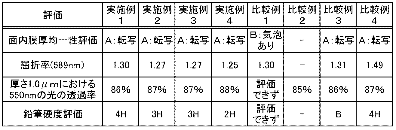
バックライトユニットを以下の方法で作製した。
図3は、実施例5において作製したバックライトユニット200の断面図である。
反射板202に実施例1の感光性転写材料を接触するように重ね合わせ、ラミネーター((株)日立インダストリイズ製(LamicII型))を用いて両者を貼り合わせた後に、感光性転写材料から支持体(ポリエチレンテレフタレートフィルム)を剥離し、その後に熱可塑性樹脂層を除去した。導光板204の端辺に光源としてランプ206とランプ反射板208とを備えるランプユニット210を用意し、導光板204と感光性低屈折率材料層とを積層させた反射板202を、感光性低屈折率材料層と導光板204とが接触するように貼り合わせた。続いて、得られた積層体をキヤノン(株)製PLA-501F露光機(超高圧水銀ランプ)で積算照射量が2,000mJ/cm2(照度:20mW/cm2)となるように露光し硬化して、ランプユニット210と反射板202を具備する導光板204を得た。同様に、拡散シート212、プリズムシート214に実施例1の感光性転写材料から感光性低屈折率材料層をそれぞれ転写して積層させ導光板204に貼り合わせ、実施例1の感光性転写材料から転写した感光性低屈折率材料層を硬化させて低屈折率層216とし、実施例5のバックライトユニット200を得た。得られたバックライトユニット200は良好な輝度を示した。
Claims (16)
- 支持体上に少なくとも感光性低屈折率材料層を有し、
前記感光性低屈折率材料層が、(成分A)中空又は多孔質粒子と、(成分B)光重合開始剤と、(成分C)重合性官能基を有するポリマーと、(成分D)モノマーと、を含有することを特徴とする
感光性転写材料。 - 成分Aが、中空シリカ粒子又は多孔質シリカ粒子である、請求項1に記載の感光性転写材料。
- 成分Dが、フッ素原子を有するエチレン性不飽和化合物を含む、請求項1又は2に記載の感光性転写材料。
- 成分Dが、フッ素原子を有する(メタ)アクリレート化合物を含む、請求項1~3のいずれか1項に記載の感光性転写材料。
- 成分Cが、エチレン性不飽和基を有するポリマーを含む、請求項1~4のいずれか1項に記載の感光性転写材料。
- 成分Cが、アリル基を有するポリマーを含む、請求項1~5のいずれか1項に記載の感光性転写材料。
- 成分Cが、重合性官能基を有する(メタ)アクリル樹脂を含む、請求項1~6のいずれか1項に記載の感光性転写材料。
- 成分Aが、中空シリカ粒子である、請求項1~7のいずれか1項に記載の感光性転写材料。
- 成分Aの含有量が、前記感光性低屈折率材料層の全質量に対し、20~90質量%である、請求項1~8のいずれか1項に記載の感光性転写材料。
- 請求項1~9のいずれか1項に記載の感光性転写材料から前記感光性低屈折率材料層を転写した感光性低屈折率転写層を有する基板。
- 請求項1~9のいずれか1項に記載の感光性転写材料を準備する工程、
被転写部材と前記感光性低屈折率材料層とが接するように前記感光性転写材料を前記被転写部材に積層する工程、及び、
前記感光性転写材料の支持体を剥離する工程、を含む
感光性低屈折率転写層の製造方法。 - 請求項1~9のいずれか1項に記載の感光性転写材料を準備する工程、
被転写部材と前記感光性低屈折率材料層とが接するように前記感光性転写材料を前記被転写部材に積層する工程、
前記感光性転写材料の支持体を剥離する工程、及び、
転写された前記感光性低屈折率材料層を露光する工程、を含む
永久膜の形成方法。 - 請求項1~9のいずれか1項に記載の感光性転写材料を準備する工程、
バックライトモジュール基板とカラーフィルター基板との間の少なくとも1層として、前記感光性低屈折率材料層と前記バックライトモジュール基板又は前記カラーフィルター基板とが接するように前記感光性転写材料を積層する工程、及び、
前記感光性転写材料の支持体を剥離する工程、を含む
光学デバイスの製造方法。 - 転写された前記感光性低屈折率材料層を露光する工程を更に含む、請求項13に記載の光学デバイスの製造方法。
- 前記光学デバイスが、バックライトユニットである、請求項13又は14に記載の光学デバイスの製造方法。
- 請求項13~15のいずれか1項に記載の製造方法により製造された光学デバイス。
Priority Applications (2)
| Application Number | Priority Date | Filing Date | Title |
|---|---|---|---|
| JP2014546978A JP6012755B2 (ja) | 2012-11-14 | 2013-11-12 | 感光性転写材料、感光性低屈折率転写層を有する基板、感光性低屈折率転写層の製造方法、永久膜の形成方法、光学デバイスの製造方法 |
| KR1020157014011A KR101716720B1 (ko) | 2012-11-14 | 2013-11-12 | 감광성 전사 재료, 감광성 저굴절률 전사층을 갖는 기판, 감광성 저굴절률 전사층의 제조 방법, 영구막의 형성 방법, 광학 디바이스 및 그 제조 방법 |
Applications Claiming Priority (2)
| Application Number | Priority Date | Filing Date | Title |
|---|---|---|---|
| JP2012-250001 | 2012-11-14 | ||
| JP2012250001 | 2012-11-14 |
Publications (1)
| Publication Number | Publication Date |
|---|---|
| WO2014077228A1 true WO2014077228A1 (ja) | 2014-05-22 |
Family
ID=50731139
Family Applications (1)
| Application Number | Title | Priority Date | Filing Date |
|---|---|---|---|
| PCT/JP2013/080492 Ceased WO2014077228A1 (ja) | 2012-11-14 | 2013-11-12 | 感光性転写材料、感光性低屈折率転写層を有する基板、感光性低屈折率転写層の製造方法、永久膜の形成方法、光学デバイス及びその製造方法 |
Country Status (4)
| Country | Link |
|---|---|
| JP (1) | JP6012755B2 (ja) |
| KR (1) | KR101716720B1 (ja) |
| TW (1) | TW201431685A (ja) |
| WO (1) | WO2014077228A1 (ja) |
Cited By (6)
| Publication number | Priority date | Publication date | Assignee | Title |
|---|---|---|---|---|
| WO2016204234A1 (ja) * | 2015-06-17 | 2016-12-22 | 東レ株式会社 | 反射フィルムおよび面光源装置用反射ユニット |
| JP2017044976A (ja) * | 2015-08-28 | 2017-03-02 | 三洋化成工業株式会社 | 感光性樹脂組成物 |
| KR101781197B1 (ko) * | 2014-08-11 | 2017-09-22 | 주식회사 엘지화학 | 반사 방지 필름 |
| JP2018072634A (ja) * | 2016-10-31 | 2018-05-10 | 東京応化工業株式会社 | 低屈折率膜形成用感光性樹脂組成物、低屈折率膜、光学デバイス、及び低屈折率膜の製造方法 |
| JP2018124409A (ja) * | 2017-01-31 | 2018-08-09 | 日東電工株式会社 | 導光板方式液晶ディスプレイ用光学シート、導光板方式液晶ディスプレイ用バックライトユニット、および導光板方式液晶ディスプレイ |
| JPWO2022176885A1 (ja) * | 2021-02-17 | 2022-08-25 |
Families Citing this family (4)
| Publication number | Priority date | Publication date | Assignee | Title |
|---|---|---|---|---|
| KR102659654B1 (ko) * | 2016-09-26 | 2024-04-23 | 삼성디스플레이 주식회사 | 표시 장치 |
| TWI783986B (zh) * | 2018-04-11 | 2022-11-21 | 日商日東電工股份有限公司 | 導光板方式液晶顯示器用光學片材、導光板方式液晶顯示器用背光單元及導光板方式液晶顯示器 |
| KR20200073816A (ko) | 2018-12-14 | 2020-06-24 | 동우 화인켐 주식회사 | 경화성 수지 조성물, 이를 이용한 광학 필름 및 화상 표시 장치 |
| JP7578878B2 (ja) * | 2021-08-26 | 2024-11-07 | デクセリアルズ株式会社 | 光硬化性材料及び画像表示装置 |
Citations (4)
| Publication number | Priority date | Publication date | Assignee | Title |
|---|---|---|---|---|
| JP2007212860A (ja) * | 2006-02-10 | 2007-08-23 | Fujifilm Corp | 積層体の製造方法、積層体、液晶表示装置用基板、液晶表示素子及び液晶表示装置 |
| JP2008146018A (ja) * | 2006-07-26 | 2008-06-26 | Fujifilm Corp | 感光性組成物、感光性樹脂転写フイルム及びフォトスペーサーの製造方法並びに液晶表示装置用基板、及び液晶表示装置 |
| JP2012013962A (ja) * | 2010-06-30 | 2012-01-19 | Fujifilm Corp | 感光性組成物、パターン形成材料、並びに、これを用いた感光性膜、パターン形成方法、パターン膜、低屈折率膜、光学デバイス、及び、固体撮像素子 |
| JP2012032673A (ja) * | 2010-06-30 | 2012-02-16 | Fujifilm Corp | 感光性組成物、パターン形成材料、並びに、これを用いた感光性膜、パターン形成方法、パターン膜、低屈折率膜、光学デバイス、及び、固体撮像素子 |
Family Cites Families (4)
| Publication number | Priority date | Publication date | Assignee | Title |
|---|---|---|---|---|
| JP4153159B2 (ja) * | 2000-12-18 | 2008-09-17 | 富士フイルム株式会社 | ネガ型感光性熱硬化性樹脂組成物、ネガ型感光性熱硬化性樹脂層転写材料、及びネガ型耐性画像形成方法 |
| JP2006293331A (ja) * | 2005-03-11 | 2006-10-26 | Fuji Photo Film Co Ltd | 光学補償シート、偏光板および液晶表示装置 |
| JP4667969B2 (ja) | 2005-06-14 | 2011-04-13 | 富士フイルム株式会社 | 黒色組成物、感光性転写材料、遮光画像付き基板、カラーフィルタ、液晶表示素子及び遮光画像の製造方法 |
| JP5622564B2 (ja) * | 2010-06-30 | 2014-11-12 | 富士フイルム株式会社 | 感光性組成物、パターン形成材料、並びに、これを用いた感光性膜、パターン形成方法、パターン膜、低屈折率膜、光学デバイス、及び、固体撮像素子 |
-
2013
- 2013-11-11 TW TW102140807A patent/TW201431685A/zh unknown
- 2013-11-12 WO PCT/JP2013/080492 patent/WO2014077228A1/ja not_active Ceased
- 2013-11-12 JP JP2014546978A patent/JP6012755B2/ja active Active
- 2013-11-12 KR KR1020157014011A patent/KR101716720B1/ko active Active
Patent Citations (4)
| Publication number | Priority date | Publication date | Assignee | Title |
|---|---|---|---|---|
| JP2007212860A (ja) * | 2006-02-10 | 2007-08-23 | Fujifilm Corp | 積層体の製造方法、積層体、液晶表示装置用基板、液晶表示素子及び液晶表示装置 |
| JP2008146018A (ja) * | 2006-07-26 | 2008-06-26 | Fujifilm Corp | 感光性組成物、感光性樹脂転写フイルム及びフォトスペーサーの製造方法並びに液晶表示装置用基板、及び液晶表示装置 |
| JP2012013962A (ja) * | 2010-06-30 | 2012-01-19 | Fujifilm Corp | 感光性組成物、パターン形成材料、並びに、これを用いた感光性膜、パターン形成方法、パターン膜、低屈折率膜、光学デバイス、及び、固体撮像素子 |
| JP2012032673A (ja) * | 2010-06-30 | 2012-02-16 | Fujifilm Corp | 感光性組成物、パターン形成材料、並びに、これを用いた感光性膜、パターン形成方法、パターン膜、低屈折率膜、光学デバイス、及び、固体撮像素子 |
Cited By (10)
| Publication number | Priority date | Publication date | Assignee | Title |
|---|---|---|---|---|
| KR101781197B1 (ko) * | 2014-08-11 | 2017-09-22 | 주식회사 엘지화학 | 반사 방지 필름 |
| WO2016204234A1 (ja) * | 2015-06-17 | 2016-12-22 | 東レ株式会社 | 反射フィルムおよび面光源装置用反射ユニット |
| JPWO2016204234A1 (ja) * | 2015-06-17 | 2018-04-05 | 東レ株式会社 | 反射フィルムおよび面光源装置用反射ユニット |
| JP2017044976A (ja) * | 2015-08-28 | 2017-03-02 | 三洋化成工業株式会社 | 感光性樹脂組成物 |
| JP2018072634A (ja) * | 2016-10-31 | 2018-05-10 | 東京応化工業株式会社 | 低屈折率膜形成用感光性樹脂組成物、低屈折率膜、光学デバイス、及び低屈折率膜の製造方法 |
| TWI742147B (zh) * | 2016-10-31 | 2021-10-11 | 日商東京應化工業股份有限公司 | 低折射率膜形成用感光性樹脂組成物、低折射率膜、光學裝置及低折射率膜之製造方法 |
| JP2018124409A (ja) * | 2017-01-31 | 2018-08-09 | 日東電工株式会社 | 導光板方式液晶ディスプレイ用光学シート、導光板方式液晶ディスプレイ用バックライトユニット、および導光板方式液晶ディスプレイ |
| WO2018143176A1 (ja) * | 2017-01-31 | 2018-08-09 | 日東電工株式会社 | 導光板方式液晶ディスプレイ用光学シート、導光板方式液晶ディスプレイ用バックライトユニット、および導光板方式液晶ディスプレイ |
| US11402569B2 (en) | 2017-01-31 | 2022-08-02 | Nitto Denko Corporation | Optical sheet for light guide plate type liquid crystal display, backlight unit for light guide plate type liquid crystal display, and light guide plate type liquid crystal display |
| JPWO2022176885A1 (ja) * | 2021-02-17 | 2022-08-25 |
Also Published As
| Publication number | Publication date |
|---|---|
| KR101716720B1 (ko) | 2017-03-15 |
| TW201431685A (zh) | 2014-08-16 |
| KR20150081314A (ko) | 2015-07-13 |
| JPWO2014077228A1 (ja) | 2017-01-05 |
| JP6012755B2 (ja) | 2016-10-25 |
Similar Documents
| Publication | Publication Date | Title |
|---|---|---|
| JP5622564B2 (ja) | 感光性組成物、パターン形成材料、並びに、これを用いた感光性膜、パターン形成方法、パターン膜、低屈折率膜、光学デバイス、及び、固体撮像素子 | |
| JP6012755B2 (ja) | 感光性転写材料、感光性低屈折率転写層を有する基板、感光性低屈折率転写層の製造方法、永久膜の形成方法、光学デバイスの製造方法 | |
| JP5618746B2 (ja) | 感光性組成物、パターン形成材料、並びに、これを用いた感光性膜、パターン形成方法、パターン膜、低屈折率膜、反射防止膜、光学デバイス、及び、固体撮像素子 | |
| JP5222922B2 (ja) | パターン形成方法、パターン形成材料、並びに、これらを用いた感光性膜、パターン膜、低屈折率膜、光学デバイス、及び、固体撮像素子 | |
| JP5816428B2 (ja) | 固体撮像素子のカラーフィルタ用感光性透明組成物、並びに、これを用いた固体撮像素子のカラーフィルタの製造方法、固体撮像素子のカラーフィルタ、及び、固体撮像素子 | |
| JP5623958B2 (ja) | 感放射線性組成物、パターン形成方法、カラーフィルタ及びその製造方法、並びに、固体撮像素子 | |
| JP5449061B2 (ja) | 感光性組成物、パターン形成材料、並びに、これを用いた感光性膜、パターン形成方法、パターン膜、低屈折率膜、光学デバイス、及び、固体撮像素子 | |
| JP5734913B2 (ja) | 感放射線性組成物、パターン形成方法、カラーフィルタ及びその製造方法、並びに、固体撮像素子 | |
| JP5743588B2 (ja) | 着色感放射線性組成物、パターンの形成方法、カラーフィルタの製造方法、カラーフィルタ、および固体撮像素子 | |
| EP2715416A1 (en) | Colored radiation-sensitive composition for color filter, pattern forming method, color filter and method of producing the same, and solid-state image sensor | |
| KR20110132240A (ko) | 중합성 조성물, 경화막, 컬러필터, 컬러필터의 제조 방법, 및 고체 촬상 소자 | |
| JP6166997B2 (ja) | 感光性樹脂組成物、赤外線透過フィルタおよびその製造方法、赤外線センサならびにカラーフィルタ。 | |
| JP5849011B2 (ja) | ソルダーレジスト組成物、硬化膜、および硬化膜の製造方法 | |
| JP5449080B2 (ja) | 感光性組成物、パターン形成材料、並びに、これを用いた感光性膜、パターン形成方法、パターン膜、低屈折率膜、光学デバイス、及び、固体撮像素子 | |
| JP5679860B2 (ja) | 着色感放射線性組成物、カラーフィルタ及びそのカラーフィルタの製造方法、並びに、固体撮像素子 | |
| JP2013054079A (ja) | 光硬化性組成物、カラーフィルタ及びその製造方法、並びに固体撮像素子 | |
| JP5618651B2 (ja) | 感光性組成物、パターン形成材料、並びに、これを用いた感光性膜、パターン形成方法、パターン膜、低屈折率膜、反射防止膜、光学デバイス、及び、固体撮像素子 | |
| JP5564589B2 (ja) | 感光性組成物、パターン膜、低屈折率膜、光学デバイス、及び、固体撮像素子 | |
| JP5647910B2 (ja) | 感光性組成物、パターン形成材料、並びに、これを用いた感光性膜、パターン形成方法、パターン膜、低屈折率膜、光学デバイス、及び、固体撮像素子 |
Legal Events
| Date | Code | Title | Description |
|---|---|---|---|
| 121 | Ep: the epo has been informed by wipo that ep was designated in this application |
Ref document number: 13855840 Country of ref document: EP Kind code of ref document: A1 |
|
| ENP | Entry into the national phase |
Ref document number: 2014546978 Country of ref document: JP Kind code of ref document: A |
|
| NENP | Non-entry into the national phase |
Ref country code: DE |
|
| ENP | Entry into the national phase |
Ref document number: 20157014011 Country of ref document: KR Kind code of ref document: A |
|
| 122 | Ep: pct application non-entry in european phase |
Ref document number: 13855840 Country of ref document: EP Kind code of ref document: A1 |